Dynamic Animation Cube Senior Design I Project ...
130
Dynamic Animation Cube Senior Design I Project Documentation Group 1 Joseph Clark Arnold Li Michael Alberts Isaiah Walker
Transcript of Dynamic Animation Cube Senior Design I Project ...

Dynamic Animation Cube
Senior Design I Project Documentation
Group 1
Joseph Clark
Arnold Li
Michael Alberts
Isaiah Walker

1
Table of Contents: 1.0 Executive Summary.....................................................................................................4
2.0 Project Description.......................................................................................................5
2.1 Project Motivations and Goals..............................................................................5
2.2 Objectives.............................................................................................................7
2.3 Project Requirements and Specifications..............................................................9
3.0 Research Related to Projects and Products................................................................13
3.1 Existing Similar Projects and Products...............................................................13
3.1.1 Boston University Senior Design Project................................................13
3.1.2 Existing Products and Homebrew Projects..............................................15
3.1.3 Instructables 8x8x8 light emitting diode Cube........................................21
3.1.3.1 Getting Started...............................................................................21
3.1.3.2 Building the Cube..........................................................................26
3.1.3.3 Building the Controller..................................................................30
3.1.3.4 Software.........................................................................................32
3.1.4 HNTE RGB light emitting diode Cube...................................................34
3.1.4.1 Building the Cube..........................................................................35
3.1.4.2 The Controller................................................................................37
3.1.4.3 Animations and Software..............................................................37
3.2 Component Research..........................................................................................39
3.2.1 LED Drivers.............................................................................................39
3.2.1.1 TLC59711....................................................................................39
3.2.1.2 TLC5947 (Texas Instruments).....................................................41
3.2.1.3 TLC5941 (Texas Instruments).....................................................42
3.2.1.4 LT3754 (Linear Technology)......................................................43
3.2.2 LED Driver Decision and Analysis.........................................................44
3.2.3 Embedded Processors..............................................................................45
3.2.3.1 Stellaris LM3S8962.....................................................................45
3.2.4 Embedded Processor Decision.................................................................47
3.2.5 Latches.....................................................................................................47
3.2.6 Latch Decision.........................................................................................49
3.2.7 Demultiplexers.........................................................................................50
3.2.7.1 CD74HC4514..............................................................................50
3.2.8 Demultiplexer Decision...........................................................................51
3.2.9 RS232......................................................................................................51
3.2.9.1 Baud Rates....................................................................................51
3.2.9.2 Crystal Oscillator.........................................................................52
3.2.10 Atmel ATmega16 Microcontroller........................................................53
3.2.11 Light Emitting Diode............................................................................54
3.3 Strategic Components.........................................................................................56
3.3.1 Wiring method of the light emitting diodes..............................................56
3.3.1.1 Charlieplexing................................................................................56
3.3.1.2 De-Multiplexing.............................................................................59
3.3.1.3 LED Drivers...................................................................................62
3.4 Architecture and Related Diagrams....................................................................64
3.4.1 Hardware Architecture...............................................................................65

2
3.4.2 Software Architecture................................................................................66
3.4.2.1 Software.........................................................................................67
3.4.2.2 GUI/Editor.....................................................................................67
4.0 Project Hardware and Software Design Detail..........................................................69
4.1 Initial Design Architecture and Related Diagrams.............................................69
4.2 Master Control Unit............................................................................................69
4.3 light emitting diode Controllers..........................................................................70
4.4 light emitting diode Lattice Architecture............................................................73
4.5 Software Design..................................................................................................74
4.5.1 System Requirements....................................................................................76
4.5.2 Functional Requirements..............................................................................77
4.6 Printed Circuit Board Requirements..................................................................78
4.6.1 Trace Thickness.......................................................................................79
4.6.2 Number of Layers of Printed Circuit Board............................................79
4.6.3 Size of Printed Circuit Board..................................................................80
5.0 Design Summary of Hardware and Software............................................................81
5.1 Simulation........................................................................................................81
5.1.1 Xilinx................................................................................................81
5.2 High Level Design...........................................................................................82
5.3 Animations.......................................................................................................85
5.4 Cube Construction...........................................................................................86
5.4.1 The Rig..............................................................................................87
5.4.2 The Panel..........................................................................................87
5.4.3 The Cube...........................................................................................88
5.5 Test Plan...........................................................................................................89
5.5.1 Objective for Main Design................................................................89
5.5.2 Testing Environment.........................................................................89
5.5.3 Stopping Criteria...............................................................................90
5.5.4 Description of Individual Test Cases................................................91
6.0 Project Prototype Construction and Coding..............................................................93
6.1 Selection of the light emitting diode Cube Kit...................................................93
6.1.1 Overall Objective for Prototype Activity...................................................93
6.1.2 Prototype High Level Design.....................................................................93
6.1.3 Testing Environment..................................................................................94
6.1.4 Stopping Criteria........................................................................................94
6.1.5 Description of Individual Prototype Test Cases........................................95
6.2 Construction of the light emitting diode Cube Kit.............................................97
6.3 Software for the Rainbowduino........................................................................102
6.3.1 Original Software for Rainbowduino.......................................................102
6.3.2 Modified Software for Rainbowduino.....................................................103
6.4 Moving Towards Group Implemented Software..............................................104
6.4.1 Replacing the Rainbowduino.................................................................105
6.5 What the Group Learned...................................................................................105
6.5.1 Construction...........................................................................................105
6.5.2 Testing....................................................................................................106
6.5.3 Programming..........................................................................................112

3
6.6 Homemade 4x4x4 Prototype light emitting diode Cube.....................................113
6.6.1 Component List and Cost.......................................................................113
6.6.2 Summary of Design Detail.....................................................................114
6.6.3 Advanced Implementation.....................................................................115
7.0 Administrative Content............................................................................................116
7.1 Milestones.........................................................................................................116
7.2 Budget and Finances.........................................................................................117
7.3 Group Members Bios........................................................................................119
7.3.1 Joseph Clark..........................................................................................119
7.3.2 Michael Alberts.....................................................................................120
7.3.3 Isaiah Walker........................................................................................121
7.3.4 Arnold Li...............................................................................................122
7.4 Division of Labor..............................................................................................123
8.0 Conclusion.................................................................................................................124
9.0 References.................................................................................................................126
Appendix.........................................................................................................................127
Appendix A Copyright Permission............................................................................127

4
1.0 Executive Summary: Within the confines of this paper, the Senior Design Group 1 from the University of
Central Florida intends to set down a set a goal for the design, construction, and testing of
a 3 dimensional light emitting diode cube that will be used to display a set of dynamic
images in a fashion that will simulate animation. Group 1 is made up of four members,
two of the members are students of Electrical Engineering and two are students of
Computer Engineering. The group will lay down an initial objective which will describe
the project and set the physical parameters that the cube will inhabit. The group will
continue by describing some of the technologies that they have researched in order to
facilitate the completion of this project, as well as the materials that will be used in its
construction. Before the project can be fully described it is necessary for one to
understand how the group came to select this particular design project.
The fundamental objective of this project is to design a dynamic animation cube capable
of displaying 3-dimensional images in such a rapid manner that the images appear to be
animated. The cube was inspired by a previously completed project at another University
which influenced this group to design and implement a bigger and better design. The
design will not provide any practical use but is intended to be displayed as a piece of
artwork. When completed, the cube will allow for the display of alpha numeric characters
as well as pre-designed images and animations without the need for external input. With
the history of the project described, it falls to the group to provide a brief description of
the physical characteristics of the cube.
The design will be approximately 3.5 feet long, 3.5 feet wide and 4 feet tall and can be
easily adjusted if needed. The light emitting diodes will be arranged in a lattice structure
with dimensions of 16 * 16 * 16. This system will require us to procure a significant
amount of light emitting diodes totaling up to a minimum of 4,096 light emitting diodes,
providing that all light emitting diodes work and none are damaged in the build process.
Below, the structure of light emitting diodes will be a solid base encased in acrylic sheets
that will house the control unit. The light emitting diodes will be supported by a system
of light emitting diode acrylic dowels that will both provide the structural support for the
light emitting diodes as well as to provide a level line in order to define the structure. The
light emitting diodes will be encased in clear acrylic sheets that will both protect the
delicate light emitting diode lattice and allow for viewing by the outside.
The implementation of this design has led to a lot of research and many ways that the
project could have been completed. First, it was necessary to figure out a system that
would allow us to control 4,096 individual light emitting diodes; in particular this led us
to one interesting technique of multiplexing. However, it quickly became apparent that
this would not be practical for the amount of light emitting diodes that this project
dictates.
With the limitations provided by the number of light emitting diodes the group would be
using, it would be necessary to find a different way of aligning the light emitting diodes
this led us to a system called Charlieplexing. The idea of how the group would align it
turned to finding its light emitting diode controllers only to find that the controller that

5
the group would eventually select would not require the more intricate technique of
Charlieplexing. With its light emitting diode drivers selected, it was time to select the
control modules that would implement all of the animations chosen by the team.
The design was the next action to accomplish. For its system, the group would eventually
settle on an axial control system. The group designed the system initially so that there
would be a Master Control Unit (MCU) that would retrieve from memory the static
images that would be flashed by the light emitting diodes in order to provide an illusion
of movement. The MCU will take the images from memory and break them into
assignments for light emitting diode controllers. As can be inferred from their name, the
controllers will be each in control of a different set of light emitting diodes on the cube.
The controllers will then plug into the light emitting diode lattice array.
The group has had to complete a significant amount of research in order to complete this
project. The project will conform to a certain amount of set parameters. It will fit into a
size factor of approximately 3.5 * 3.5 * 4 feet (L * W * H). It will contain over 4,000
individual RGB led diodes and display a minimum of 100 unique animations.

6
2.0 Project Description The establishment of a project of this size requires a clear cut description in order for the
group to work toward a unified goal. During the process of researching this project, the
group established a set of parameters that would be followed in order to produce a project
that was desirable to the all of the members. Also contained within the project
description, the group must establish a set of objectives that are to be accomplished in the
progress of completing the Dynamic Animation Cube. Finally, the group must understand
the specifications of how and in what conditions the cube will operate.
2.1 Project Motivation and Goal: The idea of producing a Dynamic Animation Cube was not the original intention of this
group. Originally the group was formed under the pretense of designing an implement
that would record the writing strokes of a non-proprietary writing implement and display
its traced path on a board to be displayed to a classroom environment. However, after a
short initial research period it was determined that this project would not be feasible to be
completed in a competent and timely manner. With this complication in mind, the group
began the process of locating a new senior design project. After the initial research
period, one of the members brought to the group’s attention a senior design project
previously completed at Boston University. All members were very pleased with the idea
of completing a Dynamic Animation Cube. The first decision the group had to make was
the determination of the final size of the completed cube. By doing some research into the
number of light emitting diodes desired to be used based on market price and the pitch of
the light emitting diodes, a size was settled on. Another feature of this project that
encouraged members to move forward was the possibility of sponsorship by the
University of Central Florida.
After selecting a project and coming up with a few ideas, the group decided to approach
their adviser to determine its viability. A short discussion was held with the adviser and
upon completion; the idea was suggested that the group seek sponsorship from the
university under the category of art. In the State of Florida, it is state law that any new
building must have a percentage of its budget allocated toward art. The group would
eventually find funding in the sum of $800 from the Electrical and Computer Engineering
(ECE) department.
The funding of the project, however, was not the key reason for this project gaining favor
within the group. Within the Harris Engineering Building, there is a piece of art known as
the lipstick enigma. Next to the lipstick enigma hangs a small plaque listing the name of
the piece of art a small description of what it is, and the artist’s name. The members of
the group hope that this will be the same case with the Dynamic Animation Cube. The
group finds the idea of having its members’ names posted within the school for future
students to see as a very enticing one, and one of the main reasons for the continuation of
this project.

7
The success or failure of this project will be based on the group’s ability to stay within
the group defined parameters and completed in a timely manner. On the physical side, the
cube should have approximate dimensions of 3.5 X 3.5 X 4 feet (LWH). The light
emitting diodes will be arranged in a primitive cubic crystalline form with a pixel pitch of
approximately 40 centimeters. The light emitting diodes will be suspended on a network
of transparent acrylic dowels and the entire light emitting diode array will be encased in a
cube of quarter inch transparent acrylic sheets. The cube will rest upon a base that will
both support the cube and house the microcontrollers used to drive the cube. The base
will be approximately 6 inches tall and will be encased in tinted acrylic sheets. The cube
will contain a minimum of 100 unique animations. These animations will include 26
animations for each of the 26 Latin characters and 10 Roman numeric characters. Further
animations will be selected and added to the project on an as desired basis.
An important feature to consider when designing an animation project must be the frame
rate. As the group increased the frame rate it would increase the continuity from frame to
frame thereby creating smoother the animation. In order for the illusion to have
continuity, it is necessary to have greater than 12 “Frames per Second” in order to create
a smooth looking animation. The group will aim for an average “Frame Rate” between 24
and 30 “Frames per Second”. Finally, it is important to consider the time frame at which
the project will be completed. An initial prototype will be completed by the end of the
week of March 14th, 2012. While the final project of this group is due the week of
August, 3rd 2012, it is the hope of this group that hope to have the project completed by
late June early July 2012.
2.2 Objectives: The senior design projects of this magnitude will inherently contain a number of goals and
objectives to be met. Among those objectives will be the structural objects, including
factors such as the light emitting diode layout and microcontroller implementation.
Contained within the project will also be the learning goal desired for the group. The
group has selected a project which it believes will allow it to learn a vast array of new
topics to build upon and enhance its already earned education. Finally, there are the
monetary and time allotments. The group hopes to complete this project under the
university allocated budget and in a timely manner by completing the project in a fashion
that substantially predates the class defined submission date. With all of these goals in
mind, the group hopes this will be a successful and worthwhile endeavor.
When completing a project of this scale, it is important to recognize the physical
necessities in order to complete the project and clearly define all parameters that must be
completed by the participating group. The most important objectives for the group to
recognize would have to be its visual parameters, as this project is intended to be a visual
art and as such it is important that it be clearly defined. The group has previously
established a requirement that the cube reside within the dimensions of 3.5 * 3.5 *
4(LWH) feet. The cube should have a professional look, with all light emitting diodes
appearing to be in an orderly fashion. This will be obtained by mounting the light
emitting diodes to an array of acrylic dowels in order to support and align them. In order
to better achieve the professional look, the light emitting diodes will be encased in clear

8
acrylic sheets to protect and enhance the aesthetic of the cube. Also all Microcontrollers,
PCBs, and assorted components will be encased in an opaque acrylic box to prevent end
users from seeing the inner workings.
Included in the physical aspects of the device must be the components that the user will
not see, but still provide the useful features. The Microcontrollers will be mounted to a
single PCB that will encase all of the processing components and the loose assortment of
parts necessary to power and control the light emitting diodes. While the physical
components are an important part of the completion of the project, the gains that the
group will earn personally must also be considered.
This project requires many different skills and technologies to complete, there may be are
skills that some or all of the group members may have little to no experience with.
First, the project will require that students become very familiar with the function and
control of light emitting diodes. The light emitting diodes that the group has elected to
use will be RGB light emitting diodes, requiring the group to learn how control not only
the on and off state of the light emitting diode, but also the color emission. Throughout
the project, the group will also become more familiar with the use and implementation of
Microcontrollers and light emitting diode drivers. This will require the group to use its
already acquired programming skills and enhance them in order to provide the graphic
functionality, which they hope to demonstrate. On top of this, the project will necessitate
the design and production of a new PCB. This will require the group to learn the skills
necessary to generate a PCB design and have it etched by a commercial board house. The
learning objectives are only one component of the many objectives that must be
considered by the group. The final set of objectives to be considered by the group is the
monetary and temporal aspects of the project.
Any project that is completed will contain some cost to be exacted upon its creator(s).
These costs can include a multitude of different expenditures. The two main expenditures
that are to be considered by this group are the monetary and temporal. In regard to the
group’s monetary situation, it has obtained funding from the University of Central
Florida department of Electrical Engineering and Computer Science. The group has been
allotted $800 dollars in order to purchase the items required to produce the cube. Within
the budget for the cube, the group also plans to purchase a prototype so it can become
accustomed to building and operating a cube on a smaller scale. With the prototype and
the materials purchased the group hopes to keeps its’ budget under $800.00 but is
prepared to spend up to $1,000.00 if it is deemed necessary. The next cost to be budgeted
will be the time allotment for completion of the project.
Based upon the experience with in the group and from outside sources, the group has
budgeted up to 200 man hours for soldering and construction, and 300 hundred man
hours for testing to get the project functioning within acceptable parameters. The project
will be due in late July, 2012 but the group has expressed a desire to complete the project
by late June, 2012 to early July, 2012.

9
The completion of the Dynamic Animation Cube will require the fulfillment of a number
of predetermined objectives by the team. The team will be required to construct the cube
to match predetermined physical specifications. These specifications include dimensions
as well as quality of appearance. The group will also be required to learn a certain set of
new skills in order to complete the project. The group will learn new skills such as PCB
design and microcontroller implementation in order to facilitate the completion of the
Dynamic Animation Cube. Finally, the group will be expected to meet certain standards
in regards to both monetary allocations to time allotment. The group has set down a set of
goals to spend approximately $800 and 500 hundred man hours to complete the Dynamic
Animation cube project.
2.3 Project Requirements and Specifications When discussing the concept of which requirements to set down in the project in order to
complete, it is readily apparent that they will fall in line with those guidelines set broadly
by the objectives discussed previously. However, the project requirements will also spell
out more directly the methods with which the objectives will be obtained.
● Cube size: 3.5 x 3.5 x 4 Ft. (L x W x H)
● Visible sides: 5 sides
● Light Emitting Diode type: RGB
● Pixel resolution: 16 x 16 x 16 = 4096
● Case construction: Transparent acrylic
● Communication: USB/ SD card controller
● Working temperature: 50-104 F
● Working Humidity: 10-80%
● Working Voltage: AC 110V-230V
● Number of animations: 100
First and foremost will be the physical constraints that the cube will inhabit. The final
dimensions of the cube was settled upon to be 3.5 x 3.5 x 4 feet (L x W x H). This
number was not an arbitrarily selected number, but was determined by the number of
light emitting diodes used in the cube. Along with the number of light emitting diodes,
the length between subsequent light emitting diodes or “Pitch” would factor into the final
size of the cube. All of these parameters would determine the length and width
dimensions of the cube; however one more component would have an influence on the
height of the cube. Underneath the cube it is necessary to create a housing to hold the
components what would control the light emitting diode selection and driving. This base
that will be constructed will add an extra maximum 6 inches to the height of the cube.
The base would also influence another design aspect of the Dynamic Animation Cube.
One of the design decisions the group would have to make would be the hosing of the
Microcontrollers and light emitting diode drivers. The group agreed that in order to
enhance aesthetic appeal of the cube, it would prefer to use an opaque base thereby
obscuring the controlling features. This design decision, however, would affect the
number of visible surfaces of the cube, thus obscuring the bottom of the cube making it
unviewable. Another factor to be taken into account is that although animations can be

10
viewed from the top, because of the nature of the animation this will not be the optimal
viewing angle. With the inherent design of the cube, it will be necessary for the group to
designate a “front”, which will be the optimal viewing angle for the cube but it will be
viewable from 5 unique angles. While the viewable angles of the cube are important,
what is probably one of the most important features of the group’s Dynamic Animation
Cube would be its colors.
From the initial concept of the cube it has always been the intention of the group to use
light emitting diodes capable of emitting more than one set of colors. With this in mind
the group elected to use Red, Green, Blue light emitting diodes. The decision to use light
emitting diodes with multiple color capabilities is a more difficult to design, but would
allow for more vibrant and diverse animations. The selection of Red, Green, Blue light
emitting diodes will, however, provide its own set of challenges. First, it will extend the
complexity of the soldering and coding for the Dynamic Animation Cube. The coding is
an issue of particular interest because it is not only the complexity of the code that is
amplified by the selection of Red, Green, Blue light emitting diodes but will also increase
the size of the code to be implemented, raising concern for memory issues. However, the
complexity of the individual light emitting diodes will not be the most hindering aspect of
the design, but rather the sheer number of light emitting diodes to be implemented.
During the process of researching the project, the group found many examples of cubes
that looked interesting. However, it was one cube in particular that really set forth the
desire to complete the Dynamic Animation Cube. The cube was a large cube, with a 16 x
16 x 16 resolution. This led the group to decide to make a 16 x 16 x 16 Dynamic
Animation Cube. With the resolution, the group calculated the number of light emitting
diodes necessary to construct the cube. With the math completed, the group established
that it would require a minimum of 4,096 light emitting diodes. This is quoted as the bare
minimum number of light emitting diodes necessary to complete the project, as more than
likely when purchasing this number of light emitting diodes some will be defective prior
to purchase and some will be damaged in the construction process. The damaging of light
emitting diodes in the construction process is an expected hazard, however post
construction the group hopes to protect its’ project.
With the projects internals completed, the group will need to find a way to not only
protect the delicate array of light emitting diodes from outside influences, but also to
allow the system to look professional and commercial. To do this, the group has decided
to use commercially available acrylic products. First, the group hopes to use small acrylic
dowels to support the light emitting diodes and to ensure that the light emitting diodes are
in alignment with respect to one another. With the “skeleton” of the Dynamic Animation
Cube completed it will be necessary to encase it in a “skin”. To do this the group will
purchase thin sheets of translucent material that will allow light to be visible from
outside, but not allow for touching of the inner system. Also, it was necessary to build a
system to protect the operating components not seen by the end user. To do this, the
group decided again to use acrylic sheets, however this time the group elected to use
sheets filled with a color dye in order to prevent the end user from observing the interior

11
components. With the inner components selected, it will be necessary to select some of
the components themselves.
As discussed in the section on the Red, Green, Blue light emitting diodes, one of the
issues with this project will be memory capacity. In order to alleviate some of the group’s
concerns with memory space, they will expand the flash memory present on the
Microcontroller with the use of Secure Digital Card. The group expanded the availability
by using a Secure Digital Micro Card. The benefit of the Secure Digital Card is that they
are cheap, ubiquitous, and most Microprocessors will work with them right out of the
box. With the memory allocated it falls to the group to meet the necessary power
requirements for not only the Microcontroller but the 4,096 light emitting diodes. When
considering the production of any product the operating conditions the product will
inhabit.
The first ambient setting to be considered is the ambient temperature. In order to
determine what temperature the Dynamic Animation Cube will operate in, it is
imperative to determine the main operating location of the device. The group has already
established that they intend to display the cube in an unknown location within the
University. This location provides a certain set of characteristics to be expected. These
locations are all temperature controlled, meaning that the device will be subjected to a
typical ambient temperature in the middle to high seventies. The group has decided to set
working temperatures from 50 degrees Fahrenheit to 104 degrees Fahrenheit, leaving it
well within the expected operating temperatures. While temperature is the first ambient
condition to be considered, it is not the only one.
The working humidity can also affect the way many electronic devices behave. However,
as established before the cube is expected to be operated in an air conditioned interior
environment. This will lead to a lower average humidity for the ambient environment.
With that in mind, the group decided to set the top end working humidity to up to 80%.
This should not be a difficult goal to reach as most electronics are capable of operating
with these relatively low levels of humidity. While the ambient conditions of the
Dynamic Animation Cube are important, these factors are all for not if the cube does not
have the power to operate.
The Dynamic Animation Cube is designed to be displayed in most settings. It is with this
in mind that the group will implement a design which can run off a single standard 120
Volt socket. The group will implement this design by using a power source similar to
those used by many laptops. The benefits of using a laptop power supply include its small
scale. The power supply is also capable of meeting the groups’ higher current
requirements to activate the 4,096 Light Emitting diodes. 4,096 is an extremely large
amount of light emitting diodes to consider, but they do not make up the entirety of the
cube; the animations will be the part of the cube that will truly impress the end user.
The animations of the cube will be the most impressive aspect of the cube, even more
impressive than the large scale of the project. The number of animations will be
important because they will represent the variability of the Dynamic Animation Cube.

12
The group has currently established a goal of reaching one hundred unique animations.
The number was a completely arbitrary number chosen by the group because it seemed
like a large enough number to present a varied pool to draw from. Some have raised the
concern that one hundred animations is a large and possibly overreaching goal to achieve.
However, the group plans on adding all alphanumeric characters and is considering them
as unique animations. As is known there are 26 different letters and 10 unique numbers.
This leads to 36 of the 100 animations leaving the group to come up with 64 new
animations.
All of these specifications are what make up the project in its entirety. The cube will have
to meet a very strict set of specifications in order to operate as expected. The cube itself
will have to fit into a certain physical constraints of 3.5 x 3.5 x 4 Ft. (L x W x H). The
cube must have 5 visible sides, Red Green Blue light emitting diodes, a pixel resolution
of 16 x 16 x 16, and a case constructed of transparent acrylic. The Dynamic Animation
Cube will also store its animations in a micro SD card, have a working temperature
between 50 and 104 Fahrenheit, a working humidity between 10 and 80%, operate on a
standard 110 volt AC socket and have 100 unique animations. This is a long list of
specifications that will be quite a goal to be accomplished but when completed it, the end
result will be an impressive site.

13
3.0 Research Related to Projects and Products: The research for this project was exhaustive. While the group has found by showing
others the potential of the project, there are no delusions that it is a unique idea. During
the initial research stage, the group found not only a previously completed cube from
another University, but also many cube kits to be completed by an end users, homebrew
projects, and even production models intended for professional display. Even though this
is not an original project, the group still has high hopes to complete an impressive senior
design project.
3.1 Existing Similar Projects and Products: There are many existing light emitting diode cubes on the market as well as a few that
were completed as senior design projects for different universities. They ranged from
simple 3x3x3 cubes, all the way up to large cubes that could fill inside an entire room.
There was also a variance in the light emitting diodes used some using tri-color, while
others simply using a single colored light emitting diode. While the single color light
emitting diode cubes were impressive, nothing compared to the tri-color cubes, which
were definitely aimed to impress. It would be wise of the group to examine these and
learn from both the successes and failures of the pre-existing projects.
3.1.1 Boston University Senior Design Project: During the research process to decide a new project, the group stumbled upon an ECE
senior design team at Boston University who constructed a similar light emitting diode
cube demonstrated on Figure 3.1, which they dubbed “Hyperion 3D”. This cube
consisted of 512 (8 * 8 * 8) light emitting diodes, and had dimensions 20” * 20” * 20”
(Length * Width * Height). The Hyperion 3D also had 16 degrees of brightness control to
add contrasts, as well as updated at 30 frames per second. They programmed the images
via a host computer using a universal serial bus port. It also appeared that the cube was
constructed in “sheets” of 8 * 8 light emitting diodes, which is a technique that the group
is hoping to replicate.

14
Figure 3.1: Boston University’s 8x8x8 light emitting diode cube. Printed with
Permission from Boston University Senior Design Team [1]
Something impressive that Boston University Senior Design Team did was to create two
GUIs that allowed the user to access the cube easily. The first GUI was used to program
the Hyperion, allowing the user to change the color/brightness of each individual light
emitting diode and see the updated values in real time. It was laid out so that each
individual 8 * 8 “slice” could be accessed one at a time and a simple drop down menu
contained the allowed values that could be programmed. The second GUI allowed for
easy transfer of images onto the Hyperions' internal flash or used to set the cube onto one
of two modes of operation; static or stream. Static is simply uploading info to the cube
via USB and on-board flash and continuous is constant updating of data from the host
computer. If static was chosen, then up to 100 images were able to be stored directly on
the Hyperion.
The way images were transferred onto the cube was also impressive. Data was sent in
packets, with each packet holding 64 bytes. The microprocessor polled for data every 4
milliseconds, allowing for a 16 KB/s upload time; more than fast enough to retrieve all
the packets of data in time for refreshing the cube. The code used to programming was C
for the Hyperion and C# for the GUI. The group will either use C# of Java for the group’s
GUI, and C for the programming of the cube due to the small overhead and minimal size
of the code as compared to C++ and Java.
The construction of the cube was also discussed. The group was quoted as saying that the
soldering took roughly 30 hours to complete. Seeing that the Dynamic Animation Cube
has four times as many light emitting diodes, the group is expecting between 110 and 130
hours of work for the soldering alone. They used 24 gauge wiring, which was small
enough that it was easily concealable and didn't appear to take away from the animation
of the cube. They also used a polycarbonate frame, which seemed sturdy enough, but was

15
visually unappealing. Another aspect the group is hoping to implement was what the
Boston University group did in terms of powering the cube. They used a simple wall
socket for power, which is straightforward and conducive to many environments.
While the Hyperion 3D performed impressively, the Dynamic Animation Cube that the
group will construct will have many improvements. First, the group’s cube will have 4
times as many light emitting diodes as the Hyperion 3D. Therefore, not only will the
Dynamic Animation Cube be inevitably larger, but it will have a higher density of RGB
light emitting diodes that will result in a higher definition picture and provide a colorful
animation.
Also, the Hyperion was not a very attractive looking light emitting diode cube. It sat atop
a plastic transparent container which housed all of the necessary components. While this
allowed for easy access and the ability to see the inner workings, it gave the appearance
of being cheap and poorly thought out. The Dynamic Animation Cube will also sit atop
its components, but the encasing that the group will use will be much more clandestine,
allowing the viewer to be awed by only the cube and not the inner workings. The
supports that were used also obscured the view of the light emitting diodes slightly. They
were thick and distracting, taking some of the mysticism away from the light display. The
group intends to use much thinner acrylic rods for the frame and have the light emitting
diodes span closer to the edges of frame, unlike the Hyperion where they ended abruptly
about an inch or two from the edge.
3.1.2 Existing Products and Homebrew Projects: During the research portion of the project, the group located a number of cubes both in
the form of consumer products and homebrew projects created by enthusiasts. Each of the
different sources provided us with different ideas that have greatly influenced the group's
final design. The production models tended to be sleek and well-built and influenced how
the group’s own cube would eventually be constructed, as far as materials and sizing. The
homebrew projects greatly influenced the ways that the group would construct its cube
based on the incredibly well written and in-depth information and tutorials provided.
Both the production and the homebrew models have greatly impacted the group’s final
product; however the one that most greatly influenced the final product structure would
have to be the production models.
During the course of the group’s research, the group discovered many websites that
display different types of light emitting diode cubes; however none influenced its design
more than the cubes at http://qubeled.com. This site allows one to purchase a cube fully
constructed, programmed, and ready to go. It was it inspired the group to see the size and
the variety of 3D light emitting diode displays that they had. Qubeled had one ranging in
size from a 5 * 5 * 5 model all the way up to the 16 * 16 * 16 model, with prices ranging
from $230.00 to $6,950.00. Figure 3.2 displays the 16 x 16 x 16 light emitting diode cube
Purchasable at their website.

16
Figure 3.2: 16x16x16 light emitting diode cube by Qubeled.
Printed with Permission from Qubeled [2]
One of the ideas adapted from their design will be the use of a layer of acrylic panel to
shield the led from outside influences. This will protect the light emitting diodes from
foreign objects bumping into and damaging the light emitting diodes and provide a
professional look. Also borrowed from their design will be the use of a solid object to
both supports the light emitting diodes and skeletal structure on which to suspend the
light emitting diodes in a linearly ordered fashion.
In between the world of true homebrew and production models, the group also found an
intermediary. During the search for homebrew products, the group found many places
that would sell “kits” containing all of the necessary pieces to construct one's own cube at
home. The interesting thing about these websites was that the group could actually select
a kit and build one in order to test the skills that would be needed to construct the cube.
The group quickly narrowed the selection down to 4 kits.
The first kit was from the web site www.seedstudios.com. The cube that came from seed
studios was a smaller cube at 4 x 4 x 4, displayed on Figure 3.3. The cube came with a
number of benefits. It came with a structure on which to mount the light emitting diodes
thereby providing a leveled skeleton to construct the cube. On top of that, it came with
the light emitting diodes, PCBs, and the through hole parts that would be necessary to
construct the cube. The cube design was also capable of working with the Rainbowduino
platform, which would allow the group a simple straightforward way to begin the process
of testing and controlling the cube. On the website, they provide simple instructions on
soldering positions and software libraries to help facilitate the hardware and software
applications. However, the Rainbowduino was not included in the package so it would be
necessary to purchase one separately. The completely constructed cube can be seen
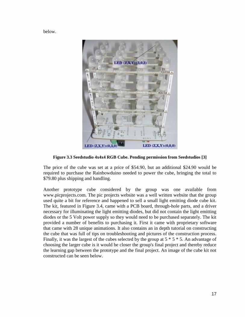
17
below.
Figure 3.3 Seedstudio 4x4x4 RGB Cube. Pending permission from Seedstudios [3]
The price of the cube was set at a price of $54.90, but an additional $24.90 would be
required to purchase the Rainbowduino needed to power the cube, bringing the total to
$79.80 plus shipping and handling.
Another prototype cube considered by the group was one available from
www.picprojects.com. The pic projects website was a well written website that the group
used quite a bit for reference and happened to sell a small light emitting diode cube kit.
The kit, featured in Figure 3.4, came with a PCB board, through-hole parts, and a driver
necessary for illuminating the light emitting diodes, but did not contain the light emitting
diodes or the 5 Volt power supply so they would need to be purchased separately. The kit
provided a number of benefits to purchasing it. First it came with proprietary software
that came with 28 unique animations. It also contains an in depth tutorial on constructing
the cube that was full of tips on troubleshooting and pictures of the construction process.
Finally, it was the largest of the cubes selected by the group at 5 * 5 * 5. An advantage of
choosing the larger cube is it would be closer the group's final project and thereby reduce
the learning gap between the prototype and the final project. An image of the cube kit not
constructed can be seen below.

18
Figure 3.4: Parts to construct a light emitting diode cube without the light emitting
diodes. Printed with Permission from Picprojects [4]
The price of the kit was $35.76. The group would also be required to purchase a power
supply and 125 light emitting diodes. RGB light emitting diodes could be purchased in
packages of 50 pieces at a price of $8.92. Since they came in packages of 50, 3 packages
would have to be purchased totaling $26.76. A 5 Volt DC power supply could be
purchased for $7 from amazon. The total purchase of the light emitting diode cube kit,
the light emitting diodes, and the power supply the total purchase would be $69.52.
Another cube the group considered purchasing was the cube provided by
www.hypnocube.com. Hypnocube provided many different prebuilt cubes at varying
prices, all of professional appearance. Amongst the varied cube that they sell, they do
also sell 1 cube kit. The cube kit contained the light emitting diodes, through-hole parts,
power supply, PCB, wires, microcontrollers, and a pre-built acrylic box designed to help
protect the constructed cube.
Of all of the cubes considered the Hypnocube, pictured in Figure 3.5, was the most
professional looking of all of the kits. The acrylic outer box provides an aesthetic that the
group hopes to replicate in the final project. It also comes preprogrammed with 51
animations, making it by far the most animations of any of the preprogrammed cubes.
However, of all of the kits the group looked at it, this was by far the most expensive. It
also came with its own microcontroller, preprogrammed with its own software
animations. This would not allow the group to experiment with animating the cube itself,
eliminating a great portion of the learning experience that the group hopes to gain by
building a prototype.

19
Figure 3.5: Encased 4x4x4 RGB cube.
Printed with Permission from Hypnocube [5]
The price of the cube kit is $150.00 making this by far the most expensive of all the kits
considered for prototyping.
The final cube considered by the group for purchase was the cube provided by
www.nutsandvolts.com. The Nuts and Volts website is actually a magazine for
electronics hobbyists; because of this they were able to provide a simple kit with a mass
of pictures. The kit is a 4 * 4 * 4 kit that included all of the parts necessary to construct
the cube. It did, however, only come in with a single color light emitting diode and
drivers only capable of handling single color light emitting diodes. The group thought
that this would not provide an accurate prototype of the finished model and therefore
would not be as beneficial as some of the other cubes. A picture of the nuts and volts kit
can be seen in Figure 3.6.

20
Figure 3.6: Materials to create a light emitting diode cube.
Pending permission from NutsVolts [6]
The final price of the cube would end up being $59.95 with no extra purchasable parts
required. This made the nuts and volts the cheapest of the cubes the group had to select
from.
In the end, there were many valid cubes that could be purchased that would all work
suitably for the purposes of prototyping of the Dynamic Animation Cube. However, of all
of the cubes one seemed to most accurately fit the criteria that group had set down for
their prototype. The group selected the Seedstudios light emitting diode cube. The cube
came at a reasonable price. Also, its addition of specialty PCB boards used to suspend the
light emitting diodes would allow for quick construction of the cube and allow the group
to begin testing software and prepare for up scaling to the 16 * 16 * 16 Dynamic
Animation Cube.

21
3.1.3 Instructables 8x8x8 LED Cube The group also came across a site titled www.instructables.com. This site provides step-
by-step instructions so that one can build their own 8x8x8 3D light emitting diode cube
on their own from scratch. It was estimated by the creator that it took about 4-5 days for
full installation of the hardware of the cube and another 4-5 days for the programming
alone. A few of the necessary skills recommended was knowledge of electronics,
soldering skills, how to use a multimeter, and basic C programming. While this design
does not represent the exact path the group will take in constructing their cube, it
provided great insight into the anatomy of LED cubes and gave a solid representation of
how an advanced model was built.
3.1.3.1 Getting Started A light emitting diode cube relies on persistence of vision. What this means is that the
cube uses multiplexing to give the illusion of 3D by stacking 2D images on top of each
other. In the case of drawing a cube, which would be lighting up all the edges of the
cube, the group would not light them all up at the same time, but rather light up each
individual layer, then turn it off and light up the next layer. The group could continue
doing this at a rate so fast that it is undetectable by the human eye, thus giving the
illusion of the 3 dimensional images, when in reality it is just many 2 dimensional images
being displayed at a very rapid rate.
Using the above setup, the author only needed 64 IO ports for the anodes and 8 IO ports
to control each layer, instead of 512 individual input/output ports to control each
individual light emitting diode. The benefit of multiplexing and only 72 IO ports is that
one would not have to worry about 512 individual wires being connected and concealed.
An LED cube can be thought of as a device constructed in columns and layers. The
positive cathode legs of every light emitting diode in each of the eight layers are soldered
together, and all the anode legs in each of the 64 columns are soldered together as well.
Each of the 64 columns (in our case it will be 256) are connected to the controller board
by a wire, and each of the 8 layers (again, in our case it will be 16) are also connected to
the board by wires. This allows that each column can be controlled individually. Each
layer is connected to a transistor which allows the user to turn the cube on and off by
controlling the flow of the current. In essence, the light emitting diodes that are to be
turned on are determined in terms of which column they are in, and transistors
determined which layer is going to be turned on and at what time.
In order to drive a single light emitting diode in a cube, two sets of IO ports are needed;
one to source the light emitting diode anode columns and one to sink the cathode layers.
For the anode side of the cube x^2 light emitting diode (64 in this case) IO ports were
used. They also used 8 IO ports to drive the cathodes. It was also discovered that for a
small light emitting diode cube, say 27 or 64 light emitting diodes, it would be acceptable
to connect the cathode layers directly to a microcontroller IO pin. However, for a larger
cube the current going through this pin will be too high to be connected directly to an IO
pin. For their 8x8x8 light emitting diode cube with only 10 mA per light emitting diode,

22
0.64 Ampere must be switched. Table 3.1 and 3.2 below provided by the author were
used to determine cube size and current requirement:
Table 3.1 Top: Displays the amount of anode and cathodes relative to the cube size.
Table 3.2 Bottom: Displays the amount of light emitting diodes per layer and the current
applied.
Printed with Permission from Instructables [7]
Another important concept that was learned was that the group must take into
consideration the amount of current that the transistor the group chose to use can handle.
With all the information online about 4x4x4 and 8x8x8 cubes, it would be easy to forget
to make all the necessary calculations before purchasing the parts that will drive our
cube.
According to this source, a microcontroller that could provide all the IO ports to control
each individual light emitting diode on a cube of this magnitude would not be feasible, so
a multiplexer to control the entire cube must be used. The multiplexer that this source
used was a 74HC574, 8 bit latch. Of course, the latch the group will use will need to be
one that holds 16 bits instead of 8, or the group may need to include more latches to meet
the full IO requirements.
The 74HC574 has the following pins, and below the IO pins the array can be seen in
Figure 3.7:
● 8 inputs (D0-7)
● 8 outputs (Q0-7)
● 1 "latch" pin (CP)
● 1 output enable pin (OE)

23
Figure 3.7: Schematic for 8 of the 64HC574 latches arranged to hold the states of the
LEDs. Printed with Permission from Instructables [7]
In Figure 3.7, a 74HC138 3-to-8 decoder is connected to the clocks of 8 of the 74HC574
latches. The job of the latch is to provide hysteresis for this cube. The latch holds 8 bits of
information which are represented on the output pins. To make an array of latches that
can remember the states of 64 light emitting diodes, 8 of these latches were used. The
inputs of all of the latches were connected together in an 8 bit bus. To handle the on and
off states of the light emitting diodes, the data was simply loaded onto the input lines, set
the latch high thus loading the data onto the output lines, set the latch low and then load
the next state of the cube, then repeat until the animation is complete.
Next, instead of using 8 lines to control each of the latches, a 74HC138, which is a 3 to 8
decoder, was used. This way, they could minimize the number of lines and eliminate
confusion.
The author also went over another solution to transfer data to the cube, this one involving
a serial-in parallel-out shift register, which gave them 64 output lines demonstrated in
Figure 3.8.

24
Figure 3.8: Schematic for 8 of the 74HC138 decoders arranged to act as shift
registers. Printed with Permission from Instructables [7]
The 74HC164, 8-bit shift register was used. This method involved using a positive edge
clock cycle to shift the data into 8 of the registers, which the state of the data input line
shifted into Q0. Next, the data input was connected to each of the 8 bits on the
microcontroller, and also had all of the clocks connected to another input/output port,
thus resulting in 9 I/O lines total. This way differs most from the first implementation
primarily because initially each byte has its own buffer all to itself. In the serial-in
parallel-out method, each byte is divided between 8 of the shift registers. It was admitted
that this would have probably been a more efficient way of handling the task, but
apparently the parts that were available were limited, thus reminding members that the
group should get all of the parts on order as to not rely on un-available hardware.
Next, this source wrote about the importance of a suitable power supply. Diodes are very
efficient, but 4096 light emitting diodes on at the same time could cause a problem. In
order to calculate the power supply that was needed, the group simply connected a light
emitting diode and a resistor the group intends to use to a 5 volt power supply, measure
the current that this gives us, and multiply that number by the total number of light
emitting diodes the group intends to use. Also, add a few milliamps for the other
components that are going to be used. It was discovered that on eBay one could purchase
power supplies for as low as $15, which would work nicely with the established budget.
Another option that the group could explore is the fabrication of a power supply. The
author details that PC power supplies are convenient because have regulated voltage with

25
high ampere ratings, which is what the group needed for the cube. If cost becomes a
problem, or if the group finds there to be extra time available, this might be an option to
consider.
Another aspect that is of the utmost importance to this group’s project is which light
emitting diodes to choose. There are several points that the author covers on which light
emitting diode is the most suitable for the job. First, the light emitting diode must be
visible from all sides, which is achievable if the group uses a diffused light emitting
diode. There are several reasons why clear light emitting diodes would not be a smart
choice, including the fact that most of the light is directed upward, as well as the light
emitting diodes illuminated the ones directly above them as well as themselves. Clear
light emitting diodes would not completely ruin the cube however, and the creator of this
cube even used clear ones to construct the cube, which looks very professional.
Next, the author recommended 3mm light emitting diodes. The reason for this being that
the light emitting diodes are going to be close together, but the group wants enough room
in between light emitting diodes to see into the other levels, which would be blocked if
larger light emitting diodes were used. Also, it goes without saying that “you get what
you pay for”. Light emitting diodes are easy to obtain through eBay and wholesalers, but
the more one pays the better quality that will be received and there will be less of a
chance that they will malfunction.
Finally, since the cube relies on multiplexing and persistence of vision, each layer is on
for one-eighth of the time the image is being processed. In essence, each light emitting
diode must be bright enough to compensate for the 1/8 duty cycle.
For choosing the resistors, the variables that were considered were the light emitting
diodes available, the 74HC574 that drove the light emitting diodes, and finally the
transistors used to switch the layers on and off. First, light emitting diodes usually have
two ratings associated with them: burst and continuous loads. The author chose to look at
the burst rating, since he was running the light emitting diodes with a 1/8 duty cycle as
mentioned in the previous step. Next, the maximum amount of current that the driver
could handle was considered. They found that the maximum rating was around 50mA, so
that gave 50/8(output pins) mA of current, so roughly 6.25mA. Finally, it would have to
be taken into account the load that the transistors would have to hold. The transistors
have to switch on and off x^2(x a single dimension of the cube) times the amount of a
single light emitting diode.
Next, this source made the choice to use the legs of the light emitting diodes to support
the cube, since they disliked the “scaffolding” that was used for other light emitting diode
cubes. First, the legs of the light emitting diodes were bent to create a 90 degree angle.
The leg was then measured to be 26mm long, so the light emitting diode spacing was
chosen to be 25 mm, thus allowing for a 1 mm overlap to work with. This allowed for
maximum visibility, making it easy to see into the furthest layer on the inside. The group
will most likely be using acrylic rods to support the cube, because it will be 16x16x16,

26
and the group did not want to rely on the strength of the light emitting diode legs to
support the design.
The author then goes on to explain how they worked on a small scale model with
dimensions 4x4x4 before jumping straight to the 8x8x8 cube so that they could get a feel
for the project that they had ahead of them. This is exactly what the group plans to do,
and this will be explained in great detail in section 7.0.
3.1.3.2 Building the Cube To make a symmetrical, eye-pleasing light emitting diode cube, the light emitting diode
must be the same distance apart, with each layer being of equal size. This was achieved
by making a soldering template crafted from a piece of wood. First, a drill bit that will
make a hole into the wood the size of the light emitting diode was used to do just that.
Next, a ruler and an angle were used to draw an 8x8 grid, using the light emitting diode
spacing of 25 mm which was previously found. Then, once the proper spacing had been
determined, the holes were drilled. Finally, a spot was marked off where they would
insert a metal brace wire, as to add support for the cube.
Now that the base was made, it was time to start soldering. The author seems to know
that people are going to buy cheap light emitting diodes, and warns that they must take
precautions when soldering. First, they must clean the soldering iron often, because
oxidation will occur. This will allow easier transfer of heat to the target area. Next,
speed is important. If the iron is in contact with the light emitting diode for too long, then
it will inevitably break. Another aspect that is important is cooling down after mistakes.
If they happen to make a mistake, they should not try again immediately because the light
emitting diode will already be hot. Instead, move on and fix the mistake when the light
emitting diode cools down.
Next, the group must consider the kind of solder to use. A thin solder was recommended
because it gives more control, and allows for more eye-appealing joints free from blobs
of solder. A 0.5 mm gauge solder was recommended, but the group will most likely
experiment with different gauges and see what works best for this cube.
Finally, it would be smart idea to go about testing each light emitting diode before and
after it is soldered to ensure it is working correctly. This seems tedious, but most likely a
necessary step. The main reason the author mentions this is because their light emitting
diode was a single, giant cube that will make getting a burnt out light emitting diode from
the furthest point in the middle a nearly impossible task. The group plan to do it in
removable layers, which means it will be easier to get to the places that are out of reach
on a solid cube. It was then detailed how to test the light emitting diode, hooking them
up to a 5 volt power supply and using a multimeter to measure the current through the
light emitting diode. As senior electrical engineering students, this should hopefully be
an easy task.

27
For the author’s actual construction of the cube, 64 light emitting diodes were inserted
into the template previously constructed. The legs were bent so that the anode was
straight in the air, and the cathode was at a 90 degree angle facing the next light emitting
diode beside it, making sure to allow for the 1 mm overlap. Since the group members are
right handed, they will take the sources advice and start soldering at the column to the far
most left. After all the light emitting diodes in a single row were soldered in this fashion,
what was left was 8 columns of light emitting diodes, only connected by a single wire at
the top row of the template. After soldering all 8 of the columns, braces were then added
to the bottom and middle of the structure for the purpose of adding support. Below is
figure 3.9 from the guide which the group then highlighted the soldered rows and
columns for easier view:
Figure 3.9: Template with Highlighted Rows and Columns Soldered. Printed with
Permission from Instructables [7]
The testing of the post-soldered light emitting diodes does not seem quite as troublesome,
and will probably be a good idea to implement after every layer that the group completes.
First, they grounded the cathode legs of the light emitting diodes at the upper corner of
the layer. They then connected a wire to a 5 volt power supply, and then to a resistor. All
that was left to do now was tap the wire against the anode leg and see if the light emitting
diode lit up. In figure 3.10 it can be seen how the LEDs were tested:

28
Figure 3.10: Testing one light emitting diode after soldering a layer. Printed with
Permission from Instructables [7]
Although the group will have a layer of 256 light emitting diodes, this will eliminate later
error handling and light emitting diode replacement. The author then gives 3 reasons
why the light emitting diode might not light up:
1. Soldering isn’t conducting current
2. Broken light emitting diode due to overheating
3. Did not make a connection between the test wire and the light emitting diode
somehow.
After soldering the individual light emitting diodes, it was time to simply straighten the
legs of the light emitting diodes so that they were rotated upward at 90 degrees and would
allow for a better looking cube. After all 8 layers were complete, what was left to do was
to solder the layers together. The anode legs of the light emitting diode were bent so that
they touched the anode legs of the light emitting diode below them.
Then, the layers are to be soldered together. The first thing the author did was to use a 9
volt battery, which is approximately 25 mm, to stabilize and hold the layers in place
while they were being soldered. The group will most likely be using “sheets” or “slices”
of light emitting diode layers, so hopefully this will be as easy as inserting the layer into a
proper location on the base, as opposed to soldering the entire contraption together.
Next, the edges of the layers were soldered together, and then moved onto each inner
layer, moving the battery as they went along. After the first layer, the battery was
removed because the cube was stable enough to support itself and be soldered in place.
Finally, it was stressed once again that testing the layers is of utmost importance, because
the soldering could have damaged on light emitting diode, or the wires might have not
been soldered together correctly. The same process as before was used to test all of the

29
light emitting diodes. The testing of the light emitting diodes seems more and more
unappealing as the project moves on, but again, the group will be using sheets to
construct the cube so testing will be kept to a minimum because there is less room for
error.
Next, they created a base from the template that was used to solder the light emitting
diodes. The group plans on going in a more professional direction and creating a custom
base. First, 8 holes were drilled into their base, as to allow for the ground to be connected
to each layer. Through each hole, a ground wire was inserted, and soldered to each
successive layer.
Circled in the figure 3.11 are where each of the ground wires were connected to the cube:
Figure 3.11: Grounded Cube Layers Highlighted. Printed with Permission from
Instructables [7]
Next, they had to attach all 72 wires to the underside of the cube. To make this easier,
they used ribbon cable so that they did not have to deal with the confusion of 72 wires
going in every direction. For the ground layer, a single 8-wire ribbon cable was used.
The 64 anodes were connected by using four 16-wire ribbon cables. At the controller
side of the ribbon cable, a 0.1 inch female header was attached that was able to be
plugged into a single row printed circuit board header pin. Below in figure 3.12, it can be
seen how useful the ribbon cable became when dealing with many wires:

30
Figure 3.12: The bottom of the light emitting diode cube. Printed with Permission
Instructables [7]
3.1.3.3 Building the Controller The author decided to go with 2 separate boards to attach all of the components. It would
have been too difficult to try and fit all the components onto one board, and two boards
with ribbon cable used to attach all the components together seemed to be the best idea
according to this source.
An external crystal with 14.7456MHz was used to drive the clock. This frequency was
chosen because an RS232 was being used so that they could run the light emitting diode
cube from a computer. Since no error correcting algorithms were being used, the author
felt like this was a smart choice as to avoid any missed signals. To prove that this
frequency was a smart choice and serial communication would be error free, it was
divided by all of the popular RS232 baud rates, and the result was a whole number every
time:
● (14.7456x10^6 Hz) / 9600 baud = 1536.0
● (14.7456x10^6 Hz) / 19200 baud = 768.0
● (14.7456x10^6 Hz) / 38400 baud = 384.0
● (14.7456x10^6 Hz) / 115200 baud = 128.0
Now that the cube was complete, they set out upon the task of creating a circuit that
would control the entire thing. They chose to start with the power supply, or the “easy”
part according to the author. The power supply consisted of a terminal where the ground
and Vcc wires were connected, along with filtering capacitors, a switch, and an light
emitting diode to indicate that the power was on. Initially, an LM7805 step down voltage
regulator was used to power the cube; however this did not work for the following
reason. A 12 volt wall wart was used, which in reality produced about 14 volts. The
LM7805 uses resistance to step down the voltage, and gives out the excess in the form of

31
heat. Even with a heat sink, 9 volts proved to be far too hot to handle, and the current
supplied was just inadequate. Instead, an external 5 volt power supply was used.
The author had to account for voltage drop across the entire circuit caused by the
switching states of the light emitting diodes. For their cube, the light emitting diodes
were going to be pulling around 500mA several hundred times per second to account for
the persistence of vision, so the voltage drop would be inevitable. By using capacitors,
they were able to create a “buffer” between the circuit and the power supply, allowing for
the power supply to compensate for the increased load. According to this source, it is
common practice for a large capacitor to be placed at the input pin of the LM7805, and a
smaller one to be placed at the output pin. Following this, a 1000uF was placed at the
input, followed by a 100uF at the output.
The next step was soldering the main components of the multiplexer array. They sought
to minimize the wiring, so the option was to place the connectors as close the ICs as
possible so no wires were used and they were only connected together on the PCB by
solder. They achieved this and managed to get all of the resistors, 74HC574s, and
connector’s snuggly on the board with room to spare.
For every 74HC574, a 0.1uF capacitor was used to reduce the noise of the circuit. This
was done because when the current on the output pins is switched on and off, this can
cause a voltage drop that would interfere with the latch. This was said to be unlikely, but
it is better to not take a chance and eliminate this from causing any errors so debugging
can proceed smoothly.
Then, wires were added to connect the 74HC574’s together. 9 wires were used per latch,
8 for the data, and 1 for the output enable. A 16 pin connector was also added, so that
latch board could be connected to the microcontroller board. A 74HC138 was then
added. This was responsible for toggling the clock on the latch. The author referred to
this as an “address selector” because it selected which of the 8 bytes in the latch array
they wished to write data to.
Next, they worked on the board containing the Atmel AVR ATmega32, or in their words,
the “brains” of the cube. It is an 8-bit microcontroller with 32KB of memory and 2KB of
RAM. It contains 32 general purpose input output (GPIO) pins, with 2 used for serial
communication, 3 for in-circuit serial-programming, and 27 to drive the cube and all
other components. The ATmega32 has 4 ports in total, with each port equaling 8 GPIO
pins. Port A and port B were used to drive the data bus of the latch array and layer select
of the transistor array because port C and D contained some of the pins used for other
operations.
Then, the author went on to work on the transistor array. This array is responsible for
switching the ground for each layer of the cube on and off. What they used was a
PN2222A NPN general purpose amplifier, which was rated at 1000mA current. For each
layer 2 of these transistors were used in parallel with the collectors connected together at
the ground, the emitters connected together and then to ground, and each base connected

32
to its own resistor. This source goes on to state that there is probably a better MOSFET
to use, but this was all that was available.
Buttons and status light emitting diodes, for debugging, were then added to the cube. The
first button added was to allow the user to choose to start the cube in autonomous mode.
The second button was there to allow for the user to start the cube in RS232 mode so that
it could be run from a computer. Finally, a reset button was added, as well as a status
light emitting diode to indicate that the cube is on or off.
The RS232 was the next component to be worked on. A PC can do floating point
calculations, which are much faster than what the AVR can do alone. The AVR has a
built in universal synchronous and asynchronous serial receiver and transmitter (USART)
that is used for communication using the RS232. To allow transfer between the RS232
and the AVR, a MAX232 was used because it sets up voltage that the RS232 can handle.
Finally, the two boards that were made were connected by two cables, a ribbon cable for
the data and address bus, and a 2 wire cable for the ground and voltage supply. The cube
was then connected to the board by four 16 wire ribbon cables, which were split into 8,
with each set of 8 connected to one of the 74HC574s.
Now, the fuse bytes must be set on the ATmega32. The fuse bits control such
information such as using an external clock source as opposed to the JTAG. Using the
software avrdude and USBtinyISP, the author was able to program the fuse bytes
accordingly.
And at last, the cube is built and the next step is testing out the cube via test code. The
test code basically checked if all the light emitting diodes were working properly and that
they were wired correctly by lighting up each light emitting diode using different patters
such a plane-by-plane, row-by-row, etc. To fully program the cube, EEPROM as well as
the firmware must be programmed.
3.1.3.4 Software The software for the cube is written in C, and compiled using with an open source
compiler, avr-gcc. The main reason the Atmel AVR microcontroller was used was
because its compiler was free, unlike many other micro-controllers. This source stated
that the software, in their mind, was going to be the easy part. However, since they were
only using a single color light emitting diode and having such low resolution proved
troublesome in making more appealing animations. Our cube will feature 3 colors, and
have a much higher resolution, so hopefully the group can build some impressing
animations.
The two main components of the software are the cube interrupt routine, and code for
making the animations. These two sections communicate via a pixel array, or a voxel
array for short. The array contains a single bit for each light emitting diode in the cube.
The voxel array that was used was: volatile unsigned char cube [8] [8].

33
This array is 8 Bytes x 8 Bytes, supplying an array that is 8x8x8 voxels. The interrupt
routine thus reads information from the cube array, updating the animations accordingly
at fast intervals.
The first thing the ATmega calls in its main function is the ioinit function. This sets up
everything that has to do with input and output, such as the ports, timers, interrupts, and
serial communications. The function of the atmega can be seen in table 3.3.
Table 3.3: Flow chart of the Input/output initializing function from Instructables.
The interrupt routine is a crucial bit of code for the light emitting diode cube. What
happens whenever the interrupt routine runs is that the present state is cleared, the data is
loaded into the next latch array, and the new layer is switched on? Also, whenever an
interrupt routine runs, the Atmegas counters reset to zero, so it can begin again until
stopped. What the author did to achieve this result was use Timer2 (of the three timers
available) with a prescaler of 128 and a counter limit value of 10.
From what the group gathers this means is that the counter is incremented by 1 every
128th clock cycle, and when it reaches 10, it is reset back to zero. Essentially, the
interrupt routine gets called 10472.7 times per second, and with a complete image
requiring 8 refreshes (one per each row of the cube) the refresh rate is 10472.7/8 =
1300FPS. According to this source, it seems like a rather high refresh rate, but through
testing with an oscilloscope they found that it only took up about 21% of the CPU time,
this allowing the other 79% to make animations which was determined to be more than
enough.
What this source did to make the code more efficient was to create a library of low level
functions. There were three main reasons why they decided to do this:
1. Memory Footprint

34
They first decided to use a 3 dimensional array to represent each of the light
emitting diodes in the cube:
Unsigned char cube[x][y][z];
However, they only needed 1 bit to represent the on/off state, so the other 7 bits
that represent each light emitting diode would be wasted. This gave the figure
512*(7/8) = 448 wasted bytes of memory. Since memory in microcontrollers is
limited, this was a sub-par solution. Instead, they went with a 2 dimensional
buffer:
Unsigned char cube[z][y];
In which the x-axis was represented in each of the bytes in the array. Since,
according to this source, this was very confusing, this led to the second reason to
use low level functions.
2. Code Readability
A voxel with the coordinate <4,3,5> would require the code:
cube[5][3] |= (0x01 << 4);
So, instead of using this notation, the author made a function in draw.c that
accepted the x, y, and z coordinates and converted them into the 2 dimensional
coordinates. They also included many functions that draw lines, fill boxes, and fill
planes which lead to the next reason for the functions.
3. Reusable Code and Code Size
Many animations rely on the same functions, so rewriting these large chunks of
code would waste vital memory. With many of these functions already written,
animations are easy to create and save a great amount of space.
Another idea that this source had was how to run the pre-programmed effects stored on
the microcontrollers memory. This will be important because once our project is done
and donated, it would be un-ideal to have someone constantly have to change the
animation. There were two ways to accomplish this; a linear path for the animations, or a
random path.
Yet another idea the group might benefit by is the use of a case statement to easily choose
the effects. As seen above, the loops send an integer to the launch_effect function. This
integer corresponds to specific animations which were chosen by the case statement.
3.1.4 HNTE RGB light emitting diode Cube Note: How Not to Engineer will be shortened to HNTE
In the later stages of the design process, the group received a site that constructed an
8x8x8 RGB cube. This is very similar to the Instructables website, but the HNTE
includes the same light emitting diodes as the Seedstudio kit and introduces the idea of

35
constructing the cube into panels. Before Nick Shulze, the cube’s designer, constructed
the RGB 8x8x8 cube, he already made a 4x4x4 RGB cube that was layered. The image
on the left reveals constructing a cube that involves many wires pointing up. It is easy to
apply the layered concept with a small scaled cube, but a large scale cube would have
difficulty soldering the light emitting diodes in the middle as well as holding the layer up
all the time. The image on the right demonstrates the 8x8x8 panel construction with the
green square and the 4x4x4 layer construction with the red square.
The group hopes to add his methodology on panel over layer construction when building
our cube. This opens up multiple options on how to construct the cube and consider the
time it takes when soldering many light emitting diodes. What is similar in both designs
is the use of a rig or base to construct the layers or panels together. Like the Instructables,
a general amount of knowledge and skills on electronics and software are recommended.
It involves “a lot about animating in color, software modulation for fading and C++ in
general” (Shulze). The group plan to construct our 16x16x16 with as much ease as
possible since his panel approach was around 20 hours of soldering with 60-80 on
software. It can be seen in figures 3.13 and 3.14 the ways that the author tried to
construct his cubes.
Figure 3.13 Left: 4x4x4 Cube with layers.
Figure 3.14 Right: 8x8x8 Cube with Panels and the 4x4x4 Cube
with layers on the bottom right.
Printed with Permission from HNTE [8]
3.1.4.1 Building the Cube Before soldering all the light emitting diodes into a panel, Shulze constructed a wooden
base with 7 columns and had all the light emitting diodes bend a certain way,
demonstrated by figure 3.15. The 3 RGB cathode wires are pointed downwards as the
grounded anode wire is bent with a sideways bent. After that, a wooden model was

36
created to serve as base for the soldering and holding the light emitting diodes. This base
is composed of 8 columns with 50 mm apart from each column.
Then, each column has blue-tack on each column to hold the light emitting diodes in
place during the soldering process. The light emitting diodes are lined up at the edge of
the board on the flat side. All the RGB wires are bent again and soldered to each light
emitting diode with respect to their color thus forming a column. Taking consideration
that the project has twice the columns, the group will slim down the distance between
each wooden column. After Shulze creates his 8 columns, he turns the columns over and
lines the top light emitting diode up with the edge of the board. The columns have their
anode wires soldered together to form a single panel. The process is done eight more
times for the 8 panels of the cube, and can be seen in figures 3.15 and 3.16.
Figure 3.15: Left: RGB cathode wires Figure 3.16: Right: The 8 panels
bent 90 degree and the ground anode wire hanging from the wooden columns.
bent 90 degrees to the side.
Printed with Permission from HNTE [8]
With the 8 panels, the wooden base gets reconstructed with the columns used to hang the
panels shown in figure 3.16. The interesting part of the hanging panels versus the layers
approach is that when soldering layers together, the layers needs to held up during the
soldering process. With the hanging approach, the wooden columns hold the top of the
light emitting diodes making the soldering procedure will have minimal mistakes.
The light emitting diodes Shulze used are exactly like the light emitting diodes the
Seedstudio kit includes. The group plan to test out a prototype of Seedstuidios' kit to
familiarize ourselves when handling the soldering and construction process. The cube
will have a magnitude of 256 light emitting diodes per panel. This will take a
considerable amount of the group’s time when constructing the cube.

37
The group hopes to reduce as much time for the testing of the cube and focus on the light
emitting diode driver board and microcontroller after it is completed. The group believes
the programming and animation portion of the cube will also take a great deal of time.
3.1.4.2 The Controller The controller involved with this project consists of two parts, an RGB light emitting
diode driver board, and a chipKit UNO which was in charge of controlling the drivers.
The driver is made up of 12 STP16 chips arranged in groups of 4 and 8 transistors. The
transistors were arranged this way so that each group can drive an individual cathode of
the LEDs, thus making it possible to have a single group drive a single color. This
impressed the group very much, and seemed like it made the circuit as well as the
programming much easier. Shulze picked the STP16 chips rather than the other driver
because he felt like they were complicated to program and difficult to handle, and he also
had prior experience with the chips with the 4x4x4 cube so he decided to stick with what
worked in the past.
These chips are cascaded with four red, four green, and four blue STP chips in each light
emitting diode. “The cascade works by pushing the data to the next byte register each
time data is loaded into the first register, this means that the first byte loaded will end up
in the last byte register” (Shulze). Therefore he can clock the RGB data at the same time.
He has the transistors and the output enable are controlled by the digital IO, this will help
switch off the drivers when data is loaded and speeds up the refresh rate. A timing
diagram displayed in a single output enable, there are 64 clock pulses that includes 64 red
bits, green bits, and blue bits. At the end of the 64 clock pulses will be the latch enable
and the start of another set of data.
The driver board is connected to the chipKit UNO microcontroller board. The board’s
applications include multiplexing and bit angle modulation to fade the colors as well as
generate animations. The layout starts with the computer generating the data. The data is
then sent to the chipKit controller. The controller receives the data and clocks that data
onto the light emitting diode driver board layer by layer. One layer is then powered with
the transistors and the STP16 chips.
3.1.4.3 Animations and Software The software used to animate the cube was greatly influenced by C++. All of his code did
not use any of the Arduino software libraries but was made by scratch, and did not take
advantage of the pulse width modulation of the LED drivers. This led to many hours of
coding, but the author felt it was the best route to take in programming his cube.
To modulate and multiplex the animations, an Interrupt Service Routine was coded. The
bit angle modulation was used to “generate a decent range of [colors] for my effects... to
fade each diode in each light emitting diode” (Shulze). Each layer has 256 interrupts.
Within those interrupts for every 2^nth interrupt, the brightness bit is loaded into the light
emitting diode. The interrupt continues until the next 2^nth interrupt to load the next
brightness bit into the light emitting diode. Bit angle modulation (BAM) is an alternative

38
to the pulse width modulation (PWM). Just like how the cube can be constructed in layers
or panels, the modulation of sending the bit to the light emitting diodes.
In terms of which modulation is better, most likely BAM since PWM requires more
processing power. The interrupt service routine also handles the multiplexing portion of
the cube. A layer is lit up one at a time, or multiplexed, and in each layer it is modulated
with BAM. As the layers a multiplexed faster and faster, it demonstrates the illusion of an
animation.
In table 3.4, the flow chart demonstrates how the interrupt service routine first applies an
animation. Each time an animation completes the microcontroller proceeds to the next
animation or uses an onboard animation. The next function uses the BAM. Data is loaded
and sent to the cube. From there it proceeds to the light emitting diode driver and
animates the cube. The bit counter is incremented and ends with the checking the bit
count to the bit length. When the bit count is higher than the bit length, it increments the
bit position and the length of the next delay. It ends with the interrupt flag resetting.
To generate colors into his animations, he used a color array to extract clear and solid
effects. He demonstrated with a color wheel that shows a circle with a blue panel at the 7
o’clock corner transitioning counter clockwise towards the 3 o’clock corner. As it is
transitioning from one corner to the other, the blue is gradually changing to red. From the
red corner, it transitions to the 11 o’clock corner. The red also changes colors towards
green. After the green corner, it returns back to the blue corner. If the color wheel was
closer to the center, the effect wouldn’t be solid and what appears to be “washed out”.
With the help of the sine function, he takes advantage of the phase to set the max bit
color for RGB outputs. For example, blue = max Bit Color x sin(0) produces a blue = 0
value and if blue = max Bit Color x sin(π/2) gives blue = max Bit Color. To take
advantage of the array, the sample code below retrieves a color from the wheel.
Table 3.4: Flow chart of the color wheel from HNTE.

39
These set of code will help the group have better understanding when dealing with the
RGB aspect of the cube. Most of the cubes the group has dealt with were monochrome or
have RGB but with little information on why it displays the RGB output. The idea of a
color wheel gives us a large boundary of colors to work with instead of the standard red,
blue, and green animations. The group can achieve brilliant and solid colors with the help
of the wheel. The finish product of Shulze’s cube was praised and appreciated by many
commenters. It was a good example before the group begins to build their cube and gives
another option to create the cube.
3.2 Component Research After getting an idea exactly how an light emitting diode cube worked, it was time to plan on
designing our own and choose the proper components to get the job done. The group had many
different variants of some parts to choose from, but they tried to stay with the Texas Instruments
parts so that they are eligible to enter into their design competition.
It was discovered that there were many parts that were suited to complete the project, so careful
consideration was taken in the selection of the components. No testing could be done to decide
which elements in a certain category were the fit for the job, so research of the components and
reading of the data sheets from the host websites had to be done in order to select the parts that
were being chosen.
3.2.1 Selecting light emitting diode Drivers Due to the large number of light emitting diodes and the group will be using light
emitting diode drivers. The light emitting diode driver will help handle the small
technical parts of lighting an LED such as the brightness and status of the light emitting
diodes as well as perform dot correction. The dot correction helps keep the brightness of
all the light emitting diodes uniform. Light emitting diode drivers may also have the
ability to sense when an light emitting diode is no lit properly or if an light emitting diode
has gone out. Using these features it will make it easier to be able to debug the
connections and ensure the light emitting diodes receive proper voltage.
There are certain criteria necessary to drive the light emitting diodes: brightness
controller, large amount of output pins, and low budget. As well as controlling the
brightness and color of the light emitting diodes, the drivers will allow us to fully control
the light emitting diodes in our cube. Most methods used only allow us to light up a
single color per layer at a time, but with the drivers the group can control each of the 256
light emitting diodes per layer allowing for much more impressive graphics. Below is an
in depth analysis of the light emitting diode drivers our group was considering on
choosing for our light emitting diode cube:
3.2.1.1 TLC59711 Product Description:
The TLC59711 is a constant current sink driver. It contains twelve channels, with eat
output channel possessing an adjustable current with 16-bit pulse width modulation
grayscale steps. There is also a global brightness control function that allows direct

40
control of each color group. The gray scale and brightness control are controlled with a
two wire signal interface.
Features:
● 12 Output Channels
● Current Control
● Grayscale Control 16-bit with Enhanced Spectrum PWM
● Brightness Control: 7-bit for each color
● Constant-Current Accuracy
● Unlimited Device Cascading
Analysis of Features:
One of the features of this device is the 12 output channels. This would allow control for
12 separate light emitting diodes via a serial interface. To control the cube, the group
needed to drive 768 separate light emitting diode cathodes. This would mean in essence
that they needed 64 of this device in order to control each individual cathode and fully
control the colors of the cube. One idea the group had was to use separate arrays to
control the individual light emitting diodes of the cube in order to avoid confusion in both
programming and the layout of the printed circuit board. With 68 of these devices it
would be difficult to make equal arrays, and more than one of the devices will be needed
to control multiple colors. Another concern about having 64 of these devices is not only
the size of the printed circuit board, but the cost. It would be a total cost of $114.95, with
each individual 59711 being $1.79.
To control the maximum output current value it is necessary to place a resistor at the
output terminal of the drivers. Because different color light emitting diodes require
different voltages to turn on, this will allow the group to take full control over every light
emitting diode in the cube by placing one of the three resistors that will be used after the
terminal that controls the light emitting diode in questions.
Grayscale pulse width modulation control is a very attractive feature of this device.
Since the light emitting diodes will be switched on and off many times per second, pulse
width modulation will allow control for the duty cycle making individual LEDs appear
brighter or dimmer. This allows the group to fully control the colors of the animations of
the cube.
Constant current accuracy is another benefit to this device. Without this feature, the cube
would not be reliable and would malfunction during animations. A more alarming
consequence of unreliable current is that fact that more than the recommended amount of
current could be supplied to a light emitting diode, or even multiple ones and cause
severe burnouts. This would result in a loss of time due to error checking and light
emitting diode replacement.
Unlimited device cascading is one of the most important features the group is looking for
in their light emitting diode drivers. Above, the idea of controlling the colors via an array
was presented. This cascading of the drivers will allow the group to transmit the state of

41
the light emitting diodes serially to each array of drivers with as few control lines as
possible. This design feature will be discussed in great detail in section 3.3.1.3.
3.2.1.2 TLC5947 (Texas Instruments) Product Description:
The TLC5947 is a constant current sink light emitting diode driver. Each of the 24
channels is individually adjustable, being controlled by 4096 pulse-width modulated
steps. Pulse width modulation control is repeated automatically with the programmed
grayscale data. There is also a thermal shutdown function causes the driver to halt
function when too high of a temperature is reached. The drivers then restart when the
temperature returns to normal conditions and function continues.
Features:
● 24 Output Channels
● 12-Bit Pulse Width Modulation Grayscale Control
● Current Accuracy
● 2 separate Transfer Rates depending on orientation
● Thermal Shutdown
● Noise Reduction
Analysis of Features:
The TLC5947 possesses 24 output channels; twice as much as the 59711. The additional
output channels makes this device more desirable than the preceding one, and the 768
cathode lines are divided nicely by the 24 outputs, resulting in 32 of the 5974 being
needed. This number is far more convenient when compared to the 64 of the 59711’s
that were needed to be used in the above implementation as far as the design detail and
the printed circuit board used.
However, if the group wanted to use three separate arrays for the colors an issue would
be that the 24 outputs do not divide soundly into the 256 separate cathodes for each color.
Also, this device has many more features than the 59711, thus meaning that the cost will
increase per unit. The overall cost would be $112.96, with each driver being $3.53.
Essentially, though the group needed only half the units, the cost of a single unit of the
5947 is almost twice as much.
Like the TLC59711, this device features pulse width modulation, current accuracy,
current control using resistors, and device cascading. However, this device is detailed
more from the Texas Instruments website in terms of the transfer rate as standalone
device as well as in cascade. For standalone, operation the device will run at 30 MHz,
but for cascade, which is what the orientation will be, the frequency of operation is 15
MHz This bit of information is very beneficial when considering the final design of our
project, and it so happens that 15 MHz is a sufficient frequency for the LED cube
communication.
Thermal shutdown is a great feature of this device. If an error would happen to occur,
this feature will prevent any damage done to the microcontroller, as well as the light
emitting diodes and other components that happen to be directly attached to the driver.

42
While the current accuracy ensures no malfunction due to the current, there are many
other unforeseeable errors that could occur. An aspect of the thermal shutdown that
would be needed to investigate is the fact that the driver restarts automatically when
proper temperature conditions are met. The group is unsure as to whether the animations
would just continue at a random section, or if it would stall the microprocessor and would
proceed where it left off.
The final feature that interests the group is the noise reduction. This is upheld by a 4-
channel grouped delay that prevents inrush current as described in the Texas Instruments
device features. This feature will prevent any unwanted bits of data being written to layer
in question, which will be beneficial if any high resolution animations are needed to be
displayed.
3.2.1.3 TLC5941 (Texas Instruments) Product Description:
The TLC5941, like the 59711 and the 5947, is a constant-current sink light emitting diode
driver. Each of the channels has a 4096 step grayscale pulse width modulation control
like the 5947, but unlike the 5947 this device also has a 64-step constant-current sink, or
in other words dot correction. The TLC5941 features two error information circuits as
well.
Features:
· 16-bit Channels ● 6-bit Dot correction
● Controlled In-Rush Current
● Two Separate Error Information Circuits
● 12-Bit Pulse Width Modulation Grayscale Control
● Current Accuracy
Analysis of Features:
The feature that drew the group to this device was the fact that it contained 16 channels to
drive the light emitting diodes, as well as the fact that this device can be operated in a
cascaded orientation like the previous two drivers. This number is of importance because
it fit the cubes dimensions, so this left the group a wide variety of ways to position the
devices and control the light emitting diodes. The orientations of the outputs of the
drivers are discussed in great detail in section 3.3.1.3.
Aside from the pulse width modulation, this specific driver has the feature of dot
correction. The dot correction ensures that all of the diodes will operated at the same
level of brightness. So, for example, if the cube has a single layer of all red colored light
emitting diodes turned on at once all 256 diodes will be the same level of intensity. This
feature isn’t necessary for the overall functionality, but it will result in a more
professional and impressive cube.
The TLC5941 also comes equipped with two separate error information circuits. The
light emitting diode open detection (LOD) lets the group know if a broken or

43
disconnected light emitting diode is at an output terminal. This is a very useful feature
seeing that the group will have 4096 light emitting diodes in the cube, so any insight into
possible errors is excellent. The thermal error flag (TEF) indicates a condition in which
the temperature becomes too high. While this last flag is not as impressive as the thermal
shutdown feature of the TLC5947, it will provide the same exact function if the group
uses the microcontroller to perform the same task by checking the status of the flag.
3.2.1.4 LT3754 (Linear Technology) Product Description:
The LT3754 is light emitting diode driver which is capable of driving up to 45 volts.
Each of the 16 channels follows a programmable current to allow anywhere between 10
to 50mA of light emitting diode current per string. The LT3754 also features pulse width
modulation like all three of the previous drivers.
Features:
● 16 Channel
● Parallel Channels for Higher light emitting diode Current
● Programmable light emitting diode Current Derating vs. Temperature
● Output Adapts to LED turn on voltage
● Fault Flag for Protection for Open LED Strings
● Short protection for LED Pin to Vout
Analysis of Features:
Like the TLC5941, this driver has the optimum amount of channels that the group feels
will make constructing the cube in the most efficient manner. One huge factor in the
choice of this driver is that the cost per unit is $6.07, making the required 48 total needed
come to the price of $247.68. This is a rather high price for the drivers alone, but given
all the advanced features of this driver the reason behind the pricing is easily seen.
This driver also protects the other components that it is attached to rather efficiently. It
has protection in the case of shorting the light emitting diode pin and the supply voltage,
a fault flag for any open light emitting diodes, and a programmable maximum voltage at
which the driver allows. Overall, this driver is high efficiency and used to provide a
stable environment for the light emitting diodes by controlling all aspects of the system.
The LT3754 can also be synchronized to an external clock, as well as operating on an
internal programmable frequency ranging from 100 kHz to 1MHz. This is very useful in
the case that the group chooses to use a computer to communicate with the cube. An RS-
232 will be used, as well as a 14.7456 crystal to act as a clock for the system. With the
two devices operating on the same frequency, the chance of error goes down drastically.
Another impressive feature of this driver is that the output voltage adapts to match the
turn on voltage of the diode it is driving. This not only ensures a long life for the diode,
but also makes the driver operate at extremely efficient levels, never wasting any power
when it isn’t necessary. Below in table 3.6 is a brief highlight of the light emitting diode
drivers:

44
Part Number Features
TLC59711(Texas Instruments)
12 Channels 16-bit Grayscale Control
7-bit Global Brightness Control for Colors
TLC5947 (Texas Instruments) 24 Channels 12-bit Grayscale Control
Thermal Shutdown
TLC5941 (Texas Instruments) 16 Channels 12-bit Grayscale Control
Error Detection
LT3754 (Linear Technology) 3000:1 True Color PWM
Table 3.6: light emitting diode drivers and features.
3.2.2 Light emitting diode Driver Decision and Analysis For the project the group will be using three TLC5941s from Texas Instruments to drive
the light emitting diodes. The TLC5941 has 16 output pins and a serial interface. It has
the 12-bit grayscale PWM to control the brightness of the light emitting diodes, and also
has dot correction which was very desirable. This light emitting diode driver also has
circuits that can detect for an open circuit which the group can use for debugging. The
group chose this light emitting diode driver mainly for its 16 output pins since they are
attempting to light such a large number of light emitting diodes, and this number happens
to fit perfectly into the plan to use arrays of the drivers to control each color individually.
Using an array of these devices arranged in a cascade pattern they will try to not only
light the 4096 light emitting diodes, but take full control over the possible spectrum of
colors that are possible to display. Other methods of lighting the LEDs also proved to be
efficient, but using this driver to control the statuses of the LEDs was the most
professional choice. This driver was also the most affordable unit from the ones the
group was considering.
The group did not choose the TLC59711 mainly because it did not have as many
channels as they would have liked. It does have more precise PWM than the TLC5941,
but that amount of precision would be wasted on the project because no noticeable effect
would have taken place over the 5941. This unit also lacked built in open light emitting
diode detection which would have made error checking and debugging a more
painstaking process. It does, however, have thermal shutdown which would have been a
welcomed addition to the circuit layout.
Even though the TLC5947 has 24 channels, it was not chosen since it would be more cost
effective to use 48 of the 5941’s as compared to the 32 of this unit. This driver also
lacked the open light emitting diode detection ability, but had the thermal shutdown built

45
in like the 59711. The group felt that it would not be that necessary to have in project as
they would try to be precise in their calculations and careful when designing their circuit.
The LT3754, while very similar to the TLC5941 in terms of output channels, was far too
expensive. The high level of circuit protection and the customizability made this device
seem perfect, and the features that it had were incredible and made all of the Texas
Instrument drivers seem weak in comparison, but overall the device was overkill. Its
applications included computer and TV monitor backgrounds, which require a high level
of precision to maintain. The groups cube will be run with the TLC5941, which will be
more than enough to ensure a solid design and long lasting performance.
3.2.3 Embedded Processors The embedded processor that is used is of utmost importance. It is essentially the brains
of the cube, performing the operations needed to display animations and controlling
individual aspects of the cube. It is vital that the group chooses a processor that is
powerful enough to get the job of integrating all the components done, and if budget
permits procure one that is overpowered to ensure no design issue that could happen to
arise would be due to the processor being ill-equipped to handle the situation.
3.2.3.1 Stellaris LM3S8962 (Texas Instruments) Product description:
The LM3S8962 contains the ARM Cortex-M3 controller core. It is capable of operating
at up to 50 MHz, and also contains 256 KB of flash memory. There are many libraries
that the group can utilize in the process of programming the controller because this is
such a popular processor. This microcontroller has many features as detailed below:
Features:
● 32-bit ARM Cortex-M3 50-MHz processor core
● 256 KB flash and 64 KB SRAM
● 42 GPIOs
● Bit-Banding
● UART
● Synchronous serial interface (SSI)
● Pulse width modulation
Analysis of Features:
The 32-bit ARM Cortex-M3 processor core is a powerful one that has many benefits. An
important aspect of all LED cubes is the interrupts. The interrupts are the essential part
to the concept of multiplexing which has been discussed in great detail. This processor
has a component called the “Integrated Nested Vectored Interrupt Controller” which
provides excellent handling of interrupts. The benefit of the interrupts in the LM3S8962
is that they are relatively quick, only consuming 12 clock cycles. This is an important
feature considering the design of the cube using serial communication to communicate
with the drivers. This communication takes up a large amount of clock cycles, so any
ability to save any cycles is greatly appreciated. These interrupts can be controlled by

46
either events such as the latch enabling on the LED drivers, or the built in 16-bit system
clock.
Another feature of the Cortex-M3 would be the ability to operate reliably up to 50 MHz
The groups cube will not operate anywhere near this high frequency because the LED
drivers and RS-232 that are being controlled by a 14.7456 MHz crystal would have a
problem running at that high of frequency. It is a benefit to have the ability to control the
frequency in case unforeseeable future events allow the group to have operation into this
range.
The memory of the microcontroller is also of great importance. The LM3S8962 has 256
KB of flash available, which should hopefully be a sufficient amount to store the states of
all of the LEDs. It is unsure at this time whether the available flash will be enough, and it
will not be clear until the group crafts a small prototype to gather information on how
much memory is consumed and how it translates to a larger implementation. This aspect
will be covered in more detail.
The amount of GPIOs that this microcontroller possesses is more than ideal. 42 GPIOs is
enough to not only control the cube using the implementation the group is planning on
using, but also leaves a sufficient amount left over for improved design features, or just in
case an aspect does not go according to plan and more need to be utilized. Aside from
the amount of GPIOs, there is also a feature to control the GPIO interrupts, and the ability
to fast toggle between separate IO’s every 2 clock cycles. Again, any amount of cycles
that can be saved is very beneficial because these operations are being performed a
sufficient amount of times every second.
To utilize memory, this microprocessor uses a method known as bit-banding. With bit-
banding, a complete word from memory can be mapped onto a single bit. This feature
oddly resembles the concept of pointers in programming languages, seeing that address
translation when reading and writing take place. The benefit of bit-banding is that the C
code written in which the animations will be programmed in will be translated into the
assembly code for the M3 in the most efficient manner. The impressive part is that the
microprocessor does this automatically, so no effort is needed on the programmers end to
make sure that this feature is in effect.
The universal asynchronous transmitter/receiver (UART) is an important device when
considering communicating to the cube via a computer. The UART communicates with
the RS-232 with the transmitting (TX) and receiving (RX) lines, and does this in a serial
manner. The LM3S8962 comes equipped with two separate UARTs, though the group is
rather certain only one will be needed.
The synchronous serial interface (SSI) is another convenient feature of the
microcontroller in question. This device is perfect for sending bits of information serially
to the LED drivers, and it has a programmable bit rate so no matter what LED driver the
group uses serially communication will precede flawlessly. It is also possible that the
SSI may be more useful than first thought. The frame size of the bits that can be sent

47
can verify between 4 and 16 bits. If 16 bits can be send at once to 16 different arrays of
LED drivers, and then the LED driver array would be 16 sets of 3 drivers as opposed to 3
sets of 16 drivers. Therefore, with the new method, it would require 48 clock cycles to
transmit the states of the LEDs serially as opposed to 256. The configuration can be
modeled anywhere in between these values, taking advantage of the extra GPIOs as
mentioned above. This is a very important feature to investigate because it could mean
the difference between a flawless image and a flickering one.
3.2.4 Embedded Processor Decision The most important part of the cube is the embedded processor. This device acts as the
brains of the cube itself, and the right choice in processor could mean the difference
between cube running animations at 14 frames per second or a cube running animations
at 30 frames per second. Since the device being constructed requires the illumination of
4096 light emitting diodes, a microprocessor that is efficient in calculations and able to
maintain the states of the diodes is a necessity.
Since only a certain number of light emitting diodes can be on simultaneously it has to
have the time to cycle through various sets of light emitting diodes to create the illusion
that more than just one set is lit at once. For the project a Stellaris LM3S8962 will be
used. This device has a powerful Cortex M3 8000 processor core which is capable of
controlling the cube. Its 32-bit processor and 3 stage pipeline architecture that has the
ability to run up to 50 MHz makes it an ideal choice for the project.
The M3 processor does not have floating point math built directly into its architecture,
which could become an issue if the group tries to do animations that require high level
math functions or involve floating point manipulation. Luckily, Texas Instruments has a
software library for the processor that allows it to do efficient floating point math without
using round about fixed point methods. The group’s biggest concern is whether the
microcontroller will have enough flash memory to contain all the statuses of the light
emitting diodes while still being able to process the calculations.
The other processor the group considered for this project was the MSP430. It however
lacks the kind of power the group would need to carry out this project, as well as
necessary GPIOs. The group considered it at first due to its low cost but quickly ruled it
out since it probably would not be able to achieve the design detail that was going to be
implemented.
3.2.5 D-Latches An alternative method to using the light emitting diode drivers was to use a decoder in
conjunction with an array of D-latches to program the data to the cube. It is explained in
detail below each set of components the importance of said component, and how it plays
a role in the data selection process.

48
3.2.5.1 SN54AHC373 Octal D-Latch Product description
The SN54AHC373 are octal D-type latches. They operate as normal latches, having
latch-enable, D input, output Q pins that allow for loading of data to be done whenever
the latch enable is set high. The device also has an output enable pin that can be used to
set the latch into two different states; normal logic where Q is high or low as governed by
the inputs D, or high impedance state where the data is not loaded and the bus lines are
not driven.
Features:
● Tri-state outputs
● Output Enable does not affect internal state of latch
● 25 mA continuous output current
Analysis of Features:
The fact that this latch has tri state outputs is a benefit to the project. The high
impedance state ensures that no data will be written to any part of the cube that the
controller does not intend to, thus eliminating any flickering or LEDs that are not
supposed to be illuminated. The method for controlling this feature is rather simple as
well, only requiring a single control line that governs the state of the method of operation.
The feature that the output enable pin does not affect the internal conditions of the latch is
also a major factor. The status of the output remains the same, but the output pins read
high impedance when output enable is low. As soon as the output enable becomes high
that data is available to be read without writing back to the input lines. This is beneficial
because there does not need to be any overhead or error checking when sending the bits
to the cube.
The 25mA output current is a required condition of the latch. Most of the LEDs run on
20mA of current, so the latch the group considers has to have at least a 20mA rating.
Having an extra 5mA is a nice feature that ensures that at least 20mA will be delivered to
the LEDs.
3.2.5.2 SN54LVTH16373 16 bit D-Latch Product description
The SN54LVTH16373 devices are 16-bit D-type latches with 3-state outputs. These
devices are particularly suitable for implementing buffer registers, I/O ports, bidirectional
bus drivers, and working registers. These devices can be used as two 8-bit latches or one
16-bit latch. The operation of this latch follows closely with that of the 8-bit latch as
mentioned previously.
Features:
● Can act as two separate 8-bit latches
● Distributed Vcc/Ground Pins Minimize Switching Noise
49
Analysis of Features:
This latch is a definite upgrade over the SN54AHC373. The 16-bit input is a major
factor in the operation of the cube, because it matches the dimensions. With 16-bits, data
can be loaded to the latch and sent to the cube in an organized fashion, either row by row
or in quadrants. Another benefit of this latch is that it can operate as two separate 8-bit
latches, thus saving room on the printed circuit board and allowing the circuit diagrams to
be more easily understood. While there are benefits to having two separate 8 bit latches,
the benefits of a compact 16-bit latch outweigh them.
The distributed Vcc and ground pins are a great feature of this device. Their purpose is to
minimize circuit noise when switching at high speeds. Since the cube will be switching
numerous times per second, this is a huge benefit because the reduced noise means less
flickering of the LEDs and the elimination of dim illumination.
3.2.6 D-Latch Decision The D-latch is another important device that plays a key role in the operation of the light
emitting diode cube. Its job is to hold the next state if the cube until it is time for this
held “frame” to be displayed. After the single frame is displayed it is then loaded with
the next image, and this process continues. The final decision was to go with a 16 bit D-
latch, simply because it fit the anatomy of our cube.
The cube from our Instructables source was 8x8x8, and the author used a series of 8 bit
D-latches. This ended up working perfectly because each latch corresponded to a
separate row of cathodes, making the process of programming run smoothly. The group
will need to use 3X16 of this type of latch to hold the states of all of our light emitting
diodes. The reason 48 is needed instead of 16 is because the group have tri-color light
emitting diodes, which will have 3 anodes instead of one.
Our other option was to expand upon the Instructables cube and use only 8 bit latches.
This proved economically irresponsible because 96 of the latches would be needed.
Also, upon investigation, the 16 bit latch the group was considering can function as two
separate 8 bit latches. Thus, they need to buy only 48 of this particular latch and if our
group changes our mind on the architecture it will be easy to recycle and conserve parts.
The latches, along with the multiplexer in the following section, play a large part in the
simplicity of the light emitting diode cube. The group could just ignore these
components, and hardwire each column of the cube, but then the group would need 768
control lines for the columns, as well as another 16 lines for the ground layers. Finding a
micro-controller with this specification would be impossible, and using an array of
simple micro-controllers would be downright confusing.
3.2.7 Demultiplexers Now that the microcontroller and the light emitting diode driver have been selected it was
time to decide on which demultiplexer the group would be using. The de-multiplexer had
to have enough outputs to control the statuses of the latches, all the while making sure to

50
cut down on the number of GPIOs that were going to be used to select which latch
received input.
3.2.7.1 CD74HC4514 Product description
The CD74HC4514 is a 4-to-16 line decoder. The output is governed by setting the enable
pin low, whereas a high on the enable pin prevents any selection of the input. De-
multiplexing is achieved by using the enable as the data input and the 4 select inputs as
addresses. When latch enable is set high the output follows the inputs from the controller
GPIOs, and when latch enable is low the output depends not on the inputs and instead
remains at the state it was in before the latch enable was toggled.
Features:
● Multifunction Capability
● 4-to-16 Decoding
● Balanced Propagation Delay and Transition Times
● Significant Power Reduction
● High Noise Immunity
Analysis of Features:
This device has the ability to act as a decoder or a multiplexer. This function is a
desirable quality to the device because the more uses for a single part, the more likely it
will come into use when constructing the control system for the cube. While the design
does not use a multiplexer at the moment, the necessity could arise in the future and this
part would perform the desired action.
The 4-to-16 decoding of this device is what made it highly desirable. Again, the 16
outputs match our design specifications, and a collection of these decoders make it
possible to control the states of the D-latches rather efficiently. The exact method of
which this device will be arranged is left for section 3.3.1.2.
The balanced propagation delay is a beneficial feature of this device. There are many
different forms of communication going on between the microcontroller and the cube, so
reliable bit transfer speeds is important as to avoid error bits or a latch not receiving all
the necessary data that it requires. The transition times fall in with the timing because if
the data is being transferred slowly from D to Q, but Q is being read before the transfer
takes place, there would be a miscommunication between the devices.
The power reduction in this device as compared to low-power Schottky transistor-
transistor logic IC’s is reduced greatly. The cube will be lighting 4096, powering the
microcontroller and various other functions so a reduction in power to any part of the
design is greatly welcomed.
High noise immunity is the final benefit to this device. Noise, as mentioned previously,
could cause many problems. It could alter the data being written to the output Q, or
perhaps distort the signal sent to the latch or output enable pins causing a false trigger

51
that reads the wrong data, or does not read only data at all causing a section of the cube to
be un-illuminated. While our microcontroller does a fine job at reducing noise, the
circuit could experience any number or errors causing false signals to be received.
3.2.8 Demultiplexer Decision The de-multiplexer used is based on which latch that the group chooses to use; 8 or 16
bit. Since the group is going with a 16 bit, it would be a wise choice to use a 4-to-16 bit
MUX. Two of these 4-to-16 muxes can be used to create a single 12-to-48 MUX. The
function of the MUX is to decide which of the 48 latches will be triggered and at what
time.
So, in essence, while the latches control which of the light emitting diodes will be turned
on or off, the MUX is in control of when this happens. The main reason the group is
using this MUX is to cut down on output lines. To control the CP pins of 48 latches, 48
output lines would be needed. Using our multiplexers, only 12 lines will be needed now.
This not only cuts down on the confusion of wiring up the cube, but also benefited in our
search for a microcontroller because the group did not need to stress over a restriction on
control lines.
3.2.9 RS-232 The RS-232 is responsible for communication between the PC and the light emitting
diode cube. A major advantage of using a PC to control the cube is that a PC can
perform floating point calculations and is capable of displaying far superior animation
that that of the micro control unit. Our groups light emitting diode will have the option of
selecting between both the control unit with pre-programmed animations and the RS232
serial interface on startup.
The RS-232 is an asynchronous device, meaning that it is not controlled by a clock. This
is a possible disadvantage because communication can begin and end at any given time,
so the possibility of encountering errors is very high. The interface the group used, as
well as the baud rate will play a major role in communication because they will not be
using any error checking. After examining many other light emitting diode cubes, there
does not seem to be any major or minor problems when dealing with the RS-232, so the
group feels that the decision to ignore error checking is in our group's best interests.
3.2.9.1 Baud Rates The baud rate is one of the most important choices the group will need to make regarding
serial communication. The baud rate is measured in bits per second, so a baud rate that is
too low will result in a low refresh rate, making 3D images flicker and be unpleasing to
the eye. However, if the baud rate is too high then there is an increased risk in
encountering errors and miss-sent bits. The baud rate the group chose has to do with the
clock frequency of the crystal oscillator they decide to use.
Though the RS-232 is an asynchronous device, the bits are sent between the cube and the
PC at predefined clock cycles. Since the group will be using a 14.7456 MHz crystal
oscillator, they must examine some popular baud rates and see which ones fit our

52
specifications. After research, some popular baud rates include 4800, 9600, 19200, and
38400. From section 3.1.3.3 the group saw that these baud rates worked well with the
oscillator.
The group will experiment with the different baud rates, but they have narrowed it down
to 9600 or 19200. The 4800 is far too low, and anything above 38400 risks errors. The
Instructables cube used 9600, but that cube was only an 8x8x8, and was not using the
methods the group will be using to drive the light emitting diodes. As seen from section
4.5 the group will be reading in the data to our TLC5941’s serially, and it will require
anywhere between 64 and 256 clock cycles for the reading alone. This leads them to
believe that 9600 might be having a chance to be lower than required, so that is why the
group is keeping their options open for the baud rate of 19200.
3.2.9.2 Crystal Oscillator The crystal oscillator the group chose to use is an important part in communication with a
computer via the RS-232. The crystal chosen was the HC-49U running at 14.7456 MHz
This frequency was found to work perfectly with the RS-232 baud rates as described in
sections 3.1.3 and 3.2.9.1. As mentioned above, serial communication is asynchronous in
the RS-232, but occurs according to the clock cycles being controlled on ends of the
devices that are in the process of communicating serially. By synchronizing the RS-232
and the computer, this crystal will ensure that communication will proceed flawlessly.
The crystal works by vibrating at a resonant frequency to produce an electronic signal
with a fairly accurate frequency. One aspect that the group needs to take into account is
the temperature of the crystal. The frequency follows the equation:
f = f0 * [1 - 0.04ppm(T - T0)^2]
While the frequency does not vary too much, it could be off by enough to begin causing
transmission errors between the two devices. However, under normal operating
conditions, the crystals are found to exhibit very little phase noise. This is ideal as to
avoid miss-triggering the devices.
A final factor to consider is the degradation over time due to heat and general stress of
operation. This could become a problem in the course of a few years of the cubes life.
However, the group plans on making the cube self-sufficient and not relying on using a
computer to perform all of its animation. It is in the best interests to produce the
animation and drive the cube using the microcontroller alone, so that they lifespan of the
cube is enhanced without any need for upkeep.
3.2.10 Atmel ATmega16 Microcontroller Although the group will not be using the ATmega16 to control our final design, it is a
perfect match for a 4x4x4 test cube that will be built to practice programming on. Below
are the specifications for the ATmega16:

53
Table 3.6: ATmega16 Specifications
As seen from the above table, the flash memory is large enough to program a sufficient
amount of small animations on that will fit the 4x4x4 architecture. The I/O pins are also
a good feature of this microcontroller. There are enough of them so that is the group
decides to perhaps upscale to an 8x8x8 test cube, there will not be an issue, especially if
light emitting diode drivers are used.
Another great feature is the external interrupts that this controller has, these being the
guiding force that switches the layers. As previously mentioned, this controller will be
scrapped and replaced by the LM3S8962 after the group gets used to programming and
using the components listed in the design of the 4x4x4 light emitting diode cube, but
there is no doubt that it will serve its purpose well. When the group finally decides to
switch over the Stellaris, many opportunities will open up in terms of wiring and
controlling. It can be seen in table 3.7 that the Stellaris is significantly more powerful
than the Atmel.
Table 3.7: Stellaris LM3S8962 specifications compared to Atmel ATmega16
The flash memory alone is enough for the Stellaris to outperform the Atmel. Combined
with it 32 bit processor and 42 GPIOs, this chip is an obvious upgrade. By incorporating

54
the LM3S8962 into the testing, it will be possible to see if a single Stellaris is enough to
provide stable conditions and animations for the cube, or if perhaps more need to be
incorporated to provide separate functions such as a single chip for animation or a single
chip for the driver control alone.
3.2.11 Light Emitting Diode The light emitting diode the group will be using for this project will be 5 mm 4 pin light
emitting diodes from “LEDs Super Bright”. The diodes come with many features that the
group finds will be beneficial to the project. The features they found helpful are:
● Common Cathode
● Red, Blue, and Green Color emission
● 5 mm diameter
● Water Clear lenses
● 20 mA forward current
● 100,000 Hours Life Rating
● 25-35 degree View Angle
● Luminous Intensity from 4000 to 5000 mcd
● 1g weight per light emitting diode
The common cathode on the light emitting diodes will make the wiring easier to
implement. This means that all of the colors on the diode will share a common cathode.
This means they only need one ground for all the colors thus greatly simplifying the
group’s wiring. This also means a cleaner solder since there will only be one cathode
wire to solder to ground. This also means if there is an issue with lighting a diode there
will only be one ground the group will have to check instead of having to check three
separate grounds. This means if a single color on an diode is messing up then the group
only has to check the wires leading to the colors and not also the ground for the color in
addition.
The fact that diodes can emit in three different colors is what is going to give the cube its
dazzling effect. Most cube tends to have only one color diode to emit from. This cube
will have red, blue, and green to make many vibrant colors with. This will add a bit of
complexity to the code however. This is due to the fact that each diode must now be
represented with 3 values instead of just one. This makes the memory requirements much
higher than if only one color was used. This will be challenge for them and will make for
engaging animations.
With the light emitting diodes being 5 mm in diameter they will take up very little space.
This will allow the group to make sure the cube will take up the smallest amount of space
possible. This will help ease issues with transporting the cube. Though the group is using
such small light emitting diodes it will still take up a decent amount of space and may
have trouble fitting through doors. This can be adjusted by lowering the pitch however if
the diodes are too close to each then the effects of the cube would be lessened. This
would be due to the light being too close together making it appear like a light blob
instead of a 3D image.

55
The water clear lens may be an issue however. This may make the light emitting diodes
too bright ruining the animations since this would cause the colors to run together,
blurring the animation. The group is planning on attempting to frost the light emitting
diodes by hand to disperse the light some to enhance the effects of the animations. If the
brightness is too much the group could always simply lower the amount of voltage
applied to make the diodes emit less light. This is only a minor issue however and should
not affect the final outcome of the project too much.
To get these light emitting diodes to work they require 20mA of current. This means it
would require about 82 amps to turn on all the light emitting diodes at once. That
situation should not occur too often however. The most that should be on at once would
be a single layer which would only require about 5 amps. This makes very efficient use
of current supplied to the cube. It also means the group may be able to supply current
another layer if the group needs to light more layers of light emitting diodes at once.
These particular light emitting diodes have a 100,000 hour life rating. This means even if
the light emitting diode was never powered off it would last about eleven and a half
years. A diode doesn’t actually burnout at 100,000 hours however it is just the point
when it loses 30% of its original luminosity. This means as long cube is only powered on
for part of the day and not constantly animating something it should be good long while
before any of the diodes need replacing. This means the cube will require very little
maintenance. In the case of a diode burning out prematurely it should not be that difficult
to replace the diode if they are not spaced to compactly together.
Viewing angle on an light emitting diode affects how focused the light coming of diode
is. A higher degree means the light is more spread out. These diodes have good viewing
angle for our purposes. If the viewing angle was too small the light from the diodes
would not spread out enough making the animations suffer in that they would only be
visible from specific positions making the cube lose its effectiveness a display for 3D
animations.
The luminosity rating on the light emitting diodes is bright enough for our needs. A rating
of 4000 mcd or mill candela means it is about 4 times as bright as a single candle. This
brightness is good enough for the groups’ purpose. It gives enough light that it should be
visible indoors with the lights on but turning the lights of should still enhance the viewing
experience. The group can also increase the voltage to make it brighter if it becomes
necessary. With over 4000 light emitting diodes it may get a little bright in a dark room
so dim lighting could make the experience better if many of the diodes are on at once.
The weight of each light emitting diode is about 1 g. This may seem like negligible
weight but the cube does us 4096 diodes. This means that the diodes alone will weigh
about 4 Kg. This weight will not include the all solder that will be used to put them
together so the group will have to make sure that the base can support the weight of all
the diodes. This is important as the group does not want the cube to collapse under its

56
own weight. The group will make sure to use sturdy material when fabricating the base of
the cube to make sure it can support the weight of all the diodes.
3.3 Strategic Components The strategy the group takes to designing this cube will not only be about the overall
implementation but also the time allotted to construct our cube. Some important issues
are the wiring methods of the light emitting diodes, the soldering of the layers and/or
sheets, and the layout of our PCB. Without proper thought, any one of these issues can
lead to design flaws, budgetary faults, and time constraints.
3.3.1 Wiring method of the LEDs A critical design feature of every light emitting diode cube is the wiring methods of the
light emitting diodes. There are many factors to take into consideration including
performance, cost, use of IO ports, and overall design. For example, one method might
use less IO ports, but the ability to control the color of the light emitting diodes in a given
layer of the cube might be restricted to a single color instead of multiple colors at once.
These design issues and solutions are discussed in the following sections in great detail.
3.3.1.1 Charlieplexing Charlieplexing was discovered in 1995 by Charlie Allen at Maxim Integrated Products.
It was used to drive a multiplexed display, and it features the tri-state logic of
microcontrollers; 1, 0, or high impedance. The main purpose of Charlieplexing is to
drive many light emitting diodes by only using a few pins. According to this source, an
accurate way to describe Charlieplexing would be “complementary drive” because the
group is complementing an existing diode with one or more extra diodes, so that they can
be powered by the same sources. In its most basic example, figures 3.17 and 3.18 shows
Charlieplexing can be used to drive 2 light emitting diodes using 2 pins of a
microcontroller.

57
Figure 3.17 Left: Driving one light emitting diode.
Figure 3.18 Right: Driving 2 light emitting diodes.
Pending permission from Instructables [9]
If pin A is supplying 5 volts, and pin B is supplying 0 volts, then LED1 will be turned on
because there will be a forward bias over the diode, and LED2 will be turned off. Now, if
the group has pin B supply 5 volts and pin A supply 0 volts, then LED2 will be on and
LED1 will be off.
Where Charlieplexing really starts to become useful is when the number of pins is
increased. For a small number of diodes, not many pins would be saved, and
Charlieplexing would be a waste of time. The numbers of light emitting diodes that can
be driven follow the equation with table 3.8 listing the amount of light emitting diodes
per pins:
#LED = #Pins * (#Pins – 1)
Pins 1 2 3 4 5 6 7 8 9
LEDs 0 2 6 12 20 30 42 56 72
Table 3.8: Number of pins to light emitting diodes.
Thus, the more pins available, the more useful Charlieplexing becomes. Take, for
example in figure 3.19, 3 pins and 6 light emitting diodes can be driven, as set-up in the
following fashion. Table 3.9 gives the on, off and don’t care values to turn on the LED.

58
Figure 3.19 Left: Schematic of three pins control the six light emitting diodes.
Table 3.9 Right: The table applies to Figure 3.19 schematic. Table of each light
emitting diode that is capable of being driven through the specific pins.
Pending permission from Instructables [9]
By supplying the light emitting diodes with either 5 volts, 0 volts, or making them high
impedance, each of the light emitting diodes can be individually driven. Making a pin
high impedance is relatively easy; just simply declare it as an input port. When pin B is
high impedance, and pin C is 5V, and pin A is 0V, LED6 will be on. It appears that
LED2 and LED 4 should be on as well, however, but due to the split of the voltages:
V(LED) = V(LED2) + V(LED4)
V(LED4) = V(LED2)
V(LED6) = 2*V(LED2&4)
Therefore V(LED4) = V(LED2) = 0.5*V(LED6)
In summary, the turn on voltage would not be supplied to LED2 and LED4, so they
would stay off while light emitting LED6 turned on. This is the same case when pin B is
high impedance, pin C if 0V, and pin A is 5V.
There are, however, several downsides to Charlieplexing:
1. Turn on Voltages
An example given by this source is the case of different color light emitting
diodes. Let’s take figure 3.19 as an example. LED5 may need 3.5 volts to turn
on, while LED1 and LED3 only require 1.9 volts. If pin A = 3.5V, pin C = 0V,
and pin B = high impedance (Z), then the voltage across LED5 will be sufficient
enough to turn it on, but the voltage across LED1 and LED3 will be 3.5/5 = 1.75.
While this is still under the 1.9 volts required to turn them on, it is enough to
perhaps cause them to emit an unwanted dim glow.
2. Dimming of light emitting diodes
Another potential problem could be the current draw from the microcontroller and
the dimming of the light emitting diodes. Since the light emitting diodes will be
turning on and off many times per second, they might appear dim. A solution is

59
to increase the current through the light emitting diodes by decreasing the resistor
size, but one would risk damaging the microcontroller.
3. Light emitting diode Failure
If a light emitting diode happens to break, the circuit will not work properly. The
broken light emitting diode will can do one of three things; an open circuit, a short
circuit, or a leaking diode which allows current in both directions. Any of these
could pose a huge problem for the entire circuit, and if the circuit is complex the
error could become difficult to correct.
4. PCB Layout
Finally, another potential problem comes from the PCB layout. The
Charlieplexed circuit is much more complicated than using simple ports to drive
the light emitting diodes, so the layout has a potential to give someone wiring it
problems.
3.3.1.2 De-Multiplexing While Charlieplexing uses significantly less lines, nothing beats the tried and true method
of multiplexing. The group decided to use multiplexing primarily because the error rate
with large numbers of light emitting diodes rises significantly with Charlieplexing, and
wiring up a multiplexed circuit is a great deal easier with as many light emitting diodes as
the group will be handling. In fact, it is not clear whether the group have enough time in
the semester to completely construct a Charlieplexed circuit of this level and complexity
even if they wanted to show off this method. Since multiplexing is such a known topic, it
will not be discussed in great detail, but rather how multiplexing will benefit this project
and the application it will have.
If multiplexer were not going to be used and the group were just going to wire every
component straight through, there would be a total of 768 anode lines + 16 cathode lines,
leading to a total of 784 total wires. This is a very large amount, and not an easy number
to work with. However with multiplexing, the group can connect 48 of the 16 bit D-
latches together, all being controlled by three 4 to 16 de-multiplexers and a single 2-to-4
de-multiplexer connected together to form a single 11-to-48 de-multiplexer. This
requires 16 control lines for the data (D0-D15) and 11 control lines(I0-I10) for the de-
multiplexer. In figure 3.21, four de-multiplexers are connected together to form a single
11-to-48 decoder.

60
Figure 3.21: Schematic of 11-to-48 decoder using three 4-to-16 de-multiplexers and
one 2-to-4 de-multiplexer.
From figure 3.21, it can be seen that lines 6 and 7 control the 2-to-4 decoder, governing
which of the latches gets selected by all three of our 4-to-16 decoders. Lines 0 to 2 will
be directly controlling the first decoder, lines 3 to 5 will be controlling the second, and
lines 8 to 10 will be controlling the third. It is easier to view by examining the truth
tables. Tables 3.10, 3.11, and 3.12 details which latch the decoder inputs will be
controlling:
Table 3.10: Control Lines 0-2 and their Functions

61
Table 3.11: Control Lines 3-5 and their Functions
Table 3.12: Control Lines 8-10 and their Functions

62
This benefits our project not only because it cuts down greatly on the amount of wiring
needing to be done, but it also makes the programming for microcontrollers a great deal
easier. It will be harder to check for errors using the scheme the group planned on, but
the benefit of reduced control lines as well as showing off our groups’ knowledge of
engineering outweighs the simplicity of wiring each component directly.
While this method is not planned on being used, it is a viable option if the LED drivers
do not work out, and will provide for sufficient animation. The fact that so many GPIOs
are saved makes this configuration beneficial, but also reduces the ability to fully control
the spectrum of colors that is introduced in the method of using drivers to control the
states of the diodes as described in the following section.
3.3.1.3 LED Drivers The way that the data will be written to the cube’s light emitting diodes is a rather simple
but effective solution. The TLC5941 is responsible for driving the light emitting diodes
by sinking the cathodes when the particular layer in question has a voltage applied to it.
The TLC reads in data serially, so the state of the layer is read in one single bit at a time
until the data for the entire layer is loaded, after which the layer shall be displayed.
There are many options on how to wire go about reading the data for the entire layer, but
the one the group are going to first try implementing is 3 sets of 16 TLCs, with each set
corresponding to a different color; red, green, or blue. So, essentially, the group will send
768 bits to all of the TLC’s 3 bits at a time, thus taking 256 clock cycles to transmit the
data for one layer. This method seems like it could require far too many clock cycles to
get the wanted number of frames per second of over 30, but as mentioned there are many
different orientations available to arrange the drivers, so if there are enough GPIOs that
are unused the option of designing a more time efficient method is a definite possibility.
After all the bits for one layer are read in, the latch enable is set high and the light
emitting diodes on the corresponding layer are illuminated. This process will be repeated
16 times with the data for each subsequent layer being read in the same way. Then, this
pattern will either be repeated to form a still image, or new data will be read in the case of
animations. As mentioned there are many configurations to be investigated, but as a start
the group will try the arrangement of 3 sets of 16 drivers which is the simplest
configuration available. Below is figure 3.22, a modified image from our “How Not to
Engineer" source detailing the design that the group intends to fabricate:

63
Figure 3.22: Modified TLC Layout. Pending permission from HNTE [8]
Also, figure 3.23 is a modified image of the timing diagram that will be implemented. It can be
seen that 256 clock cycles will be needed in order to read in the data serially for the 256 light
emitting diodes in the given layer if this particular method of orienting the drivers is used:
Figure 3.23: Modified Timing Diagram. Pending permission from HNTE [8]

64
As seen from the images above, the states can be written 3 at a time with one bit going to
red, one bit going to green, and one bit going to blue. This opens up a whole new set of
animations that can be displayed by our cube in terms of the different combinations of
colored diodes being lit at once. The other options only allowed for a single color per
layer to be turned on at a single instance. That meant that is light emitting diode (0,0,0)
was red, there was no way for light emitting diode (0,0,1) to be green, blue, or a
combination of the three.
Also, this opens up the opportunity for a large variety of colors. Since the 48 TLC’s
drive each individual cathode, the group can have various colors per layer, and have
animations similar to the color wheel as described in section 3.1.4. The group believes
that this would be an outstanding feature to implement and required by them to provide a
cube that significantly outperforms expectations.
The group can experiment with not only different combinations of red, green, and blue,
but also the intensity of each color, thus providing a large array of visual hues. This is
exciting because it allows us to not only program animations, but perhaps implement a
random color scheme. This means that when being viewed, a person will never see the
same exact color animation twice.
It is unsure as to whether 256 clock cycles will be too many to provide a smooth image
considering that the group will still have to use multiplexing to display animations.
These details cannot become concrete until a test cube is built and animations are seen on
it. This will give insight into the scalability of the code and the possible amount of
memory that the animations will require when applied to a larger design.
If it turns out that the massive amounts of clock cycles becomes a problem with the
animation, it will be relatively simple to alter the design and implement 6 rows of 8 TLCs
with two rows controlling each of the three colors instead of one. This will allow a
transmission rate of 6 bits instead of 3. This will cut the cycles down to 128, and only
require adding 3 extra data lines to our micro control unit which will not be a problem.
The proposed solution is only one of the ways in which the timing can be cut in half, but
this sacrifices more GPIOs, so careful consideration needs to be taken when selecting the
configuration of the drivers and the amount of control lines needed.
3.4 Architecture and Related Diagrams The architecture of the cube does not only include the wiring of the light emitting diodes
and the components used, but the abstract view of the code used to program animations to
the cube, and the GUI for which the group will control the cubes animation from a
computer. The architecture is rather advanced, and compared to the smaller 4x4x4 and
8x8x8 LED cubes that have been witnessed by the group; the diagrams and specifications
for a 16x16x16 cube are immense in form. Though they are much larger, the scalability

65
of the cubes tends to be rather simple, so even though there are many more components,
the general design and architecture remains somewhat unaltered.
3.4.1 Hardware Architecture The architectural design of each cube focuses on having the exact same amount of light
emitting diodes for the length, width, and height. A few of the LED “cubes” investigated
had the same amount of diodes for the length and width, but the high was significantly
larger, created a column. There were even some designs that formed a spherical mass of
LEDs, which was very impressive to view. While these devices were visually pleasing,
the group feels that a cube with equal length, width, and height would be the best design
choice in terms of building and of viewing.
A layer of light emitting diodes are soldered and aligned with relative to the width and
the length. By soldering the layers on top of each other, or in horizontal sheets depending
on the desired architecture, this creates a cube. The finished shell will have to be
supported by either acrylic rods or by strategically placed metal wire in order to prevent
damage due to force exerted by the higher layers upon the lower ones.
What is of utmost importance when soldering the light emitting diodes is to know which
the cathode and anode leg are and that the light emitting diodes are functional. This could
become a problem when using diodes with 4 legs, but the common anode or common
cathode is usually the longest leg of the LED. The light emitting diodes, if they are
common anode, are structured so that the anode wires are connecting each of them to one
another. Likewise, common cathode LEDs must be soldered so that the cathodes are
connected sequentially. There cannot be any mistakes in the architecture of the cube, else
some areas may not work or light up due to various errors including short circuits and
open terminals.
Depending on the size of the cube, the amount of time to solder each light emitting diode
will increase as the size of the cube increases. As the dimensions are relatively increasing
with the same length, width, and height, the amount of light emitting diodes
exponentially increases and so will the time to construct it or, to be more precise, the
number of LEDs to solder increases by a factor of X^3.
When considering scaling down the LED cube due to size constraints, it wasn't until the
group considered making the cube 14x14x14 did they realize this fact. With dimensions
equaling 14, this gave a total of 2744 light emitting diodes to be soldered. A small scale
down factor of 2 eliminated 1352 light emitting diodes from the overall design, which
was rather shocking when seen on paper.
The construction of the cube also describes the pixel quality of the animations. The
tighter the light emitting diodes are packed together, the greater the quality of the cube,
but decreases the size and presentation. The larger the cube, the pixel quality decreases.
This was also an issue that arose when deciding whether to scale down in terms of LEDs
or to decrease the spacing between the LEDs. It was found that decreasing the spacing

66
was not a desirable option because the vision into the cube would not allow the viewer to
see all the diodes at once, thus causing an altered image when viewed from only a single
position.
Scalability is never an issue for LED cubes. Generally, cubes range from 4x4x4 to 8x8x8.
Most projects give the light emitting diodes a reasonable amount of area so they are not
too far apart or clustered very close to each other. This scalability is a benefit to the
group because building a 4x4x4 and an 8x8x8 prototype will give valuable insight into
the construction of the cube at the earliest possible time.
The most important part of the cube besides the direct architecture of the LEDs would be
the controller. Without the proper controller, the communication between the code and
the cube would produce nothing in effect because the circuit would be riddled with
errors. LED cubes tend to have a general board that includes capacitors, resistors, a few
light emitting diodes, transistors, the microcontroller, and the PCB board which may
come in as surface-mounted or through-hole. Before these controllers are put together, a
schematic diagram is created for the purpose of where to place each object.
Schematic diagrams give a general idea of how each and every part communicates with
each other. It can also prevent mistakes when soldering and connecting boards with each
other. The Seedstudio rainbow LED cube kit includes a board and a microcontroller as
well as the parts to put together on the board. For the 4x4x4 Seedstudio cube, the
architecture of the controller is fairly small. For the 8x8x8 Instructables cube, it needed
considerable amount of work and planning before soldering parts together. Constructing
the light emitting diode cube is a simple but tedious task involving nothing but soldering
and correct positioning, but constructing the circuit for the controller is a difficult and
important job that needs to be taken slowly and constantly documented.
A completed cube can be displayed in the open or an encased in acrylic sheets. Many
projects featured small cubes without a cover and within their residences. When
presenting the project to the public, it is recommended to cover the cubes in a casing so
the light emitting diodes will not be damaged from any outside forces. These cubes are
very fragile and can be easily destroyed. The cube does not have to be encased, if not
needed. For this project, the cube will be encased for protection and demonstration. It
will be donated and displayed to UCF.
3.4.2 Software Architecture The animations and images are demonstrated through different types of code
programmed to the microcontroller, or through a GUI to set the color and timing of the
light emitting diodes from a host computer. Sample code and libraries are available
online for various other LED cubes to get an idea of how to code animations and the
operations of turning on the light emitting diodes as well as specific coloring schemes for
tri-color LEDs. The software is where the Dynamic Animation Cube shines and becomes
more impressive. There are countless options and ideas for animations, and the group
plans to implement a large amount of well-thought ones.

67
3.4.2.1 Software Writing the animations in software would probably be the most efficient. Having large
amounts of animations cycle over is easily accomplished with loops and if’s statements.
There are different ways the software in written, for example, in C, C++, C#, Java, and
libraries provided online. One type of technique to animate the cube is to use
multiplexing to give the illusion of a 3D image by flashing each layer of the cube one
after another at a fast rate.
An interrupt routine would be necessary when multiplexing the cube to control when the
layers should be switched on and off and how long each layer should be turned on for.
When an interrupt runs, the cube will clear the previous layer and load the next layer and
light that set of light emitting diodes. This process happens a multitude of times per
second, and for a frame rate of at least 30 frames per second this interrupt will occur 16
times for a single image, 30 times per second resulting in 480 calls to the interrupt routine
every second. For this reason alone, it is important to develop efficient and compact code
so that animation will proceed smoothly.
The Instructables website included a sample raindrop effect that looked very impressive,
even though it was a rather simple process for displaying the animation. This raindrop
effect had a randomized loop that picked a pixel on the top layer and had it appear to
“fall” down the entirety of the cube all the way to the bottom most layer. It is animations
such as these that make the cube so versatile and able to impress with rather simple code.
If animations are well thought out and efficiently written, then it will be a high possibility
of using a single microcontroller to not only control the LED drivers but also be used to
produce the animations and hold the states of the LEDs. This is a highly desirable
feature, because the other option is to use multiple controllers with a single overhead
controller governing their functions. This means that there will be much more
complicated printed circuit board layouts and translation of control signals.
When coding with colored light emitting diodes, the hexadecimal values corresponding to
the color are needed to choose which color LED was supposed to be illuminated.
Efficient code will take advantage of this and provide easy to read functions that handle
color choosing wisely. Seedstudio demonstrated the use of hexadecimal colors with
0x00FF00 as Green and 0x0000FF as blue. With the Rainbowduino library provided by
Seedstudio, it is possible to simulate certain layers with a solid green and a solid blue,
randomized colors for all light emitting diodes, and provide a night lamp effect. Software
and libraries are available anywhere given the time to look. It is not limited to the internet
as new and different animations can be created with a series of loops and if statements.
3.4.2.2 GUI/Editor A GUI or an editor to select specific light emitting diodes and color may sound like an
optimal, but rather a tedious approach with a great amount of animations. The editor
functions as a way to pick specific light emitting diodes on the cube and then the color.
This will count for one frame of the animation. It will take many frames to equate to a
decent animation. To animate a letter may take a great amount of frames compared to a
couple lines of code. The editor would be better suited for small projects and to test the

68
cube’s capabilities. The editor would be best to use to test the performance, voltages,
current, and if the light emitting diodes are in working condition. For example, the editor
can light up all the light emitting diodes to check for any burned out light emitting diodes
on the cube that may need replacing or check if each light emitting diode can display an
RGB output.
An alternative to using a GUI to program each individual it is to have one that can be
capable of selecting pre-programmed animations. This will allow the user to cycle back
and forth through the various animations with the click of a button. Features could be
easily added to the GUI, for example an option to slow down or speed up an individual
animation so the process of multiplexing of the layers can be viewed. A color changing
option would be a great feature to have, so that the user could change the color or
intensity of the animation.
If time permits, a GUI would be a great feature to implement that would add a polished
feel to the overall cube. The fact that the group could allow their peers to toggle the
animations and make it a more hands on experience is a desirable feature. However,
since the cube is going to be intended to run self-sufficiently, using its own
microprocessor to generate the animations, this feature might not be implemented.

69
4.0 Project Hardware and Software Design Detail Now that the group have all the parts selected and the general knowledge of light
emitting diode cubes needed to construct the final project, it is time to investigate in
detail how all the components will work together to form the final implementation. An
important concept is hardware and software code sign. This project has allowed our
group great insight on just how these two work together to form a single, final
implementation. They are not writing software and then building hardware around the
code, nor are they blindly constructing a lattice of light emitting diodes and hoping to
find a way to code the light emitting diodes to turn on. Along every step of the way the
group has taken into consideration both aspects of the design and chosen parts that suit
the needs that the hardware and software have brought into focus.
4.1 Initial Design Architecture and Related Diagrams There are various ways to design the hardware of the light emitting diode cube. The most
common way is to construct the light emitting diodes in layers or sheets, and then put the
pieces together. For our project it was decided that the easiest way to go about the
construction was to solder the layers of light emitting diodes, then erect them in vertical
layers. The group believes that a 16x16 sheet of light emitting diodes will be far too
difficult to put together in the method described in the Instructables tutorial as mentioned
in section 3.1.3.
One of the most important pieces in the construction of the layers will be the jig. A
proper jig will ensure that the spacing between each light emitting diode is uniform
throughout the entire layer, thus ensuring a cube that will be of top quality. One design
that caught our eye was that of the jig described in section 3.1.4. This jig allows for easy
soldering of light emitting diode, and the use of blue tack to hold the light emitting diodes
in place is a tactic that our group will be adopting.
However, our group cannot simply copy this method of wiring the light emitting diodes,
because where the one soldered using this method was 8x8x8, ours will be significantly
larger. This means that the group will have to find a method to support the cube from
becoming damaged in construction, possibly using acrylic cylinders or even a larger
gauge wire to maintain stability.
4.2 Master Control Unit To control the light emitting diode cube, the group will be using a Texas Instruments
Stellaris LM3S8962. The group chose this particular microcontroller partly because it
was introduced to them through a TI seminar, but more importantly because it fits all our
requirements, plus some extra.
The group initially thought that they would need at least three of this micro control unit,
with perhaps one extra to act as the brains behind the three. However, the LM8962 has
42 GPIOs, which is more than enough given our design to control the entire light emitting
diode cube. This means that the group might only need a single MCU if the design

70
persists. Below is a rough design specification of the GPIOs needed for out cube:
● 3 or 6 or 12 TLC serial data lines (explained in section 4.4)
● 1 TLC latch enable
● 1 TLC output enable
● 1 TLC anode control line
● 2 RS232 lines
● 3 In-Circuit Serial Programming lines
Total: 11, 14, or 20 control lines depending on the architecture of the light emitting diode
drivers.
As seen above, the LM3S8962 will have more than the required GPIOs. This will allow
for possible alteration of the design for improved performance and simplification of
operation. In the next section the possible configuration of the LED drivers is discussed
in detail, where the control lines needed from the Stellaris will be decided upon.
4.3 LED Controllers To drive the light emitting diode the group will be using the Texas Instruments TLC
5941. There are many different configurations to go about serially transmitting data to
the TLC, and they plan to use the one that has the highest frame rate without sacrificing
the amount of GPIOs that are needed. The following methods detail the different
approaches of connecting the TLCs and the GPIOs that will be needed for each method:
Method 1. 3 sets of 16 lined up in series:
This method requires the least amount of GPIO, but sacrifices time. It will take 256 total
clock cycles to read in the data, and one extra to enable the latch to transmit the state to
the cube. This is by far the simplest and most straightforward implementation which will
allow for each group to control the different colored diodes. Below is a summary of the
GPIOs needed:
● 3 TLC 5941 Serial Data Lines
● 1 TLC 5941 Serial Ground Control Line
● 1 TLC Latch Enable Bus
● 1 TLC Output Enable
Total = 6 GPIOs
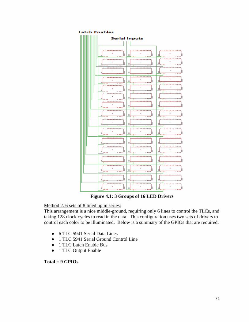
71
Figure 4.1: 3 Groups of 16 LED Drivers
Method 2. 6 sets of 8 lined up in series:
This arrangement is a nice middle-ground, requiring only 6 lines to control the TLCs, and
taking 128 clock cycles to read in the data. This configuration uses two sets of drivers to
control each color to be illuminated. Below is a summary of the GPIOs that are required:
● 6 TLC 5941 Serial Data Lines
● 1 TLC 5941 Serial Ground Control Line
● 1 TLC Latch Enable Bus
● 1 TLC Output Enable
Total = 9 GPIOs

72
Figure 4.2: 6 Sets of 8 LED Drivers
Method 2. 12 sets of 4 lined up in series
This method will be the quickest, but it will require a large amount of GPIOs. This will
take only 64 clock cycles and will give the quickest read time, but it might be
unnecessarily fast for what the group requires. This method is the most desirable in terms
of speed and performance, but if it is implemented then the group might have to
incorporate more than one microcontroller to drive the cube, which would mean and
altered printed circuit board and more overhead. Below is a summary of the GPIOs
needed:
● 12 TLC 5941 Serial Data Lines
● 1 TLC 5941 Serial Ground Control Line
● 1 TLC Latch Enable Bus
● 1 TLC Output Enable
Total = 15 GPIOs

73
Figure 4.3: 12 Sets of 4 LED Drivers
The method the group will use depends on the software to display the animations, most
importantly the interrupt service routine. The group wants to have a refresh rate high
enough so that the viewer believe they are seeing a 3D image, but not high enough as to
where the increased speed is unnoticed and all the extra work was for nothing.
4.4 LED Lattice Architecture A critical design feature is the lattice of light emitting diodes. The entire control
architecture depends on this section alone, so it is very important that our group sticks to
the desired architecture that they initially pick. It was agreed upon that the light emitting
diodes will have all of their cathodes in each row connected together, and all of the
anodes in a given layer connected together as well. This means that the light emitting
diodes that the group will order will be common anode light emitting diodes, meaning
each light emitting diode will have a single anode and three separate cathode legs for
corresponding to each color. In figure 4.1, it displays the view of the front of the cube
and displays the wiring tactics that our group plans to use:

74
Figure 4.4: Light emitting diode wiring architecture as viewed from the front side of the
cube.
4.5 Software Design The group will be writing most of the code for the cube ourselves as there are not any
libraries around for 3D light emitting diode cubes for the Stellaris microcontroller. The
group will attempt to make the code as efficient as possible so that they can achieve the
high refresh rate needed to make use of the persistence of light effect. Figure 4.1 shows
outline our code’s architecture.

75
Table 4.1: UML Diagram of code Library
The main base of our code will be the Cube class. This class will handle holding the
buffer for the light emitting diodes as well as handling the ISR used to send the signals to
the hardware. It uses the Point structure as a way of passing the X, Y, and Z parts of a
point to it. This may change to a non-encapsulated version if it proves to be too
inefficient though. This also holds a pointer to a sprite which the class that the group will
be using to hold a sprite. This is also where many of the basic functions are handled, such
as drawing points and lines. The translate and rotate functions are applied to entire cube
and can be used to add extra effects to the animations.
The Cube class also defines some port names for use with interfacing with the hardware.
The various devices and their ports will be defined in this file and used to send the signals
to them. The Sprite class holds the frames of an animation that cannot be modeled easily
using a math function. How this data is held in both the Cube class and Sprite class may
change if can find a more efficient way of storing it. The 4D array holds the frames of
animation. The first index is the frame number and the subsequent indices represent
corresponding points in the 3D cube buffer. Each sprite will have its own frame delay
which will be used by its handle function to denote when it should change to the next
frame in its animation.
When a sprite is animating it will continuously loop through all of its frames until another
command is given. There is also a function for going to specific frames which will
probably mostly be used to debug the sprites. If there is time the group may make an
application that can be used to make sprites. There is one drawback to the sprite class in
that each frame is the size of the cube. This may cause some memory problems if the
group is not careful.
To define an animation that can be modeled using math functions or logically the group
will simply write the function out and place it in the main loop to be handled. A class will
not be necessary for this as it will most likely just involve simple for loops and if
statements and making a class for that will probably be overkill.

76
To run the code the group will have a Main file that will hold a single instance of a Cube.
A Sprite can be attached to the cube while it is being initialized. Also during its
initialization it will set up the timer for its ISR. If it has a sprite attached it will simply go
through the frames of the sprite forever unless some other commands are inside the main
loop. Inside the main loop is where animations that use logic can be placed to run.
Whether through logic or a sprite the Cube’s light emitting diode array will get filled with
values to be sent to the actual light emitting diode cube. This is done by the ISR which
will trigger based on a timer. Every time the ISR is tripped it will send the signals to the
various light emitting diode drivers so that the light emitting diodes will get turned on.
This must happen very rapidly as only a small set of the light emitting diodes can be lit at
once. This will happen repeatedly going through the buffer constantly to make whatever
is in the buffer appear on the light emitting diodes. As the buffer is changed by the code
so will the light emitting diodes.
4.5.1 System Requirements The dynamic animation cube as an entire system will have a set of requirements it will
have to meet in order to run. These requirements vary from the specifications because
they were not explicitly selected by the group but a rather a group of requirements
determined by the physical hardware and software decisions that the group has already
made. The group has determined that it needs to meet the following requirements in order
to successfully complete the design.
● The program of each set of animations include flash memory of 256 bytes of
memory or greater.
● A working Voltage of 110V-230V AC.
● Must be able to produce up to 82 Amps of current
● 50 MHz of processing speed
● The code will generate colors and apply the colors on the animated effects
● The code will be compatible with the Stellaris microcontroller based on the code
the group writes and the software libraries provided from Texas Instruments.
When the group decided to use the Stellaris microprocessor one of the first limitations
that they set upon themselves was the limited amount of flash memory build on the
processor. The Stellaris comes with a built in flash memory size of 256 bytes. With the
way the memory is designed on the Stellaris processor anything stored in the flash
memory will be easier for the processor to retrieve and therefore increase the speed at
which the processor can manipulate the light emitting diodes thereby increasing the
frames per second. With this specification in mind the group needs to try to make each
individual frame of animation fully described in the size requirement of 256 bytes so that
each animation can be displayed at the proper time in a smooth and efficient manner.
When the group initially decided to produce the Dynamic Animation Cube they felt in
order to make it as functional as possible it would need to run off of a standard socket
rather than having battery backs or extreme power supply requirements. The best way to
complete this task was to use a prebuilt power supply like those commercially available

77
on a desktop computer. This would allow the group to meet their high current demands
while still keeping the project within normal electrical component bounds.
The most demanding limitation for the production of the Dynamic Animation Cube
would be the total power draw of 4,096 light emitting diodes. The diodes that the group
has selected have typical current draw of 20 ma regardless of which of the three color
states are being used. This means that the total current the group is going to require is
around 82 Amps. The group has found what they believe to be a clever solution by using
2 separate desktop computer power supplies each to provide half of the required current
to power both the light emitting diodes and the rest of the operating components.
When the group decided to use the Stellaris microprocessor it also set the maximum
clock limit that the system could function at to 50MHz. The group has decided to run the
system at the allowable 50 MHz because it will allow them the easiest path to reach their
goal of a minimum of 30 frames per second. This will allow for an approximately 83
thousand clock cycles per animation. This number was established by taking 50 MHz
which is the temporal equivalent of .4 nanoseconds. It each clock cycle is .4 nanoseconds
that equates to 2,500,000 clock cycles per second. If the group wishes to have 30 frames
per second the number of clock cycles per second is divided by the 30 frames they wish
to produce leaving the group with approximately 83 thousand clock cycles per animation.
One of the most important features that will set the Dynamic Animation Cube apart from
many of the homebrew projects across the internet will be the cubes’ ability to display
animations in a spectrum of colors versus the simplicity of many of the other
monochromatic cubes on the internet. To do this though the group will have to write a
set of code capable of not only turning on and off individual light emitting diodes but will
need to also select what color a diode that is turned on is to display. This will require us
to put a more complex code than most of the other cubes the group has seen produced.
4.5.2 Functional Requirements
● The code must be able to generate sample animations. These animations can
range from lighting up certain areas of the cube, produce a rain effect, or generate
letters or numbers.
● These animations will also be capable of mixed color effects. The color effects
will be based off a color wheel. The color was influenced by the HNTE RGB
Cube project.
● Efficient code in C and C++
● High refresh rate for persistence of vision
To meet the functional requirements the group will write code to generate the various
animations. The code should be memory efficient enough to function on the Stellaris built
in flash memory. A library of letters will be made to help in the displaying of letters in an
efficient manner. Many of the animations will have to be based in loop logic so that the
memory will not be able to hold the data for too many 3D images. To make the colors
more vibrant the group will use a color wheel data structure from a similar project to

78
avoid colors that would be dull and unsatisfying. To achieve this efficient code the group
will be writing the code in C and C++ as they are very efficient languages. Most of the
code will be C as it has lower memory footprint. The code must also be optimized
wherever possible to make sure it runs as fast as it can. With this efficient code the group
hopes achieve the high refresh rate to make use of the persistence of vision to make sure
the images on the cube do not flicker.
To make the sample animations the group will use simple logic based animations. These
type of animations will not be saved as a series of frames in a 3D array but will use loops
to fill the buffer with information. They will iteratively loop and based on simple logic
send various things to the buffer. This technique can be used to create rain effects,
sweeping motions, or even explosion effects. These type of animations would simply
require a function and would not take up much space.
The colors that cube uses will be based a concept learned from the HNTE site.
Generating colors randomly may seem easy at first however there are a lot of colors that
will have a washed out feel when done this way. This because the colors have to be
randomly generated by 3 numbers. These each refer to the amount of red, blue, or green
light and this can easily lead to unbalanced ratios that lead to the washed out effect. So to
limit the colors generated to be only the colors that are not washed out we will use the
color wheel approach from HNTE to generate an array of valid colors which will be used
to choose the random colors for the animations.
Writing the code mostly in C will give the group the fast execution time it needs for the
persistence of vision to work well. Using mostly C will limit the type of data structures
that can in the coding. This means the amount of classes in the code will be very few.
C++ is also more memory intensive meaning the group will try avoid using it wherever
possible. This could mean just writing everything in C to avoid hassles that could arise.
Utilizing the persistence of vision will be very important in the implementation of this
project. Getting the light emitting diodes to flicker at a rate above what the human eye
can perceive will allow the cube to function without utilizing a lot of current at once. This
puts very tight constraints on the code since it has to be very efficient to be able to run in
a manner that will allow it to send data to 256 lights emitting diodes in 16 different layers
rapidly enough to not give the illusion all the light emitting diodes are all on without
them all actually being lit.
4.6 Printed Circuit Board Requirements: For the printed circuit board there are many considerations that must be accounted for in
order to ensure a successful project. One of the most important factors to consider are the
thickness of the traces so the group is not current limited. The group also needs to
consider the number of layers that will be used because that will affect the ease with
which they can lay out the board. Finally, the group needs to consider the overall size of
the board as it determines the size of the base.

79
4.6.1 Trace Thickness The trace thickness is determined by a couple of limiting factors. First, the group needs to
decide how much current will be necessary to drive all of the light emitting diodes. The
current structure will contain a system of 16 * 16 * 16 light emitting diodes totaling up to
4,096 units. The current required to drive the light emitting diodes that the group will use
is 20 mA. To calculate the maximum possible current draw it is necessary to assume that
all diodes will be lit at one time. If all light emitting diodes are turned on at one time and
they are all drawing 20mA of current then the group can assume that the total maximum
current draw is 81.92 A rounded for this project to 82 A.
However, the group does not need to assume that any one trace will be carrying all 82A
at any given time as this current will be divided between the 48 different light emitting
diode drivers. If the maximum current of 82 A is divided down to the 48 light emitting
diode drivers then that maximum current any one trace will handle is 1.708 A rounded up
to 1.8 A for this project. With the maximum current that any one trace will have to carry
the group needs to decide how much heat the traces will create based on the current
passing through them. This is an important number because if the heat rise is allowed to
be too great the printed circuit board could fail prematurely.
For our particular printed circuit board the group expects the cube to be in a primarily in
a ambient temperature of 21 degrees Celsius. With the ambient temperature in mind the
group decided that a temperature rise of 10 degrees Celsius would not be a high enough
temperature to cause premature failure of our printed circuit board and components. With
the max current known it was time to determine the thickness of the traces required to fit
these specifications. For the traces there will be different sizes if the trace is to be on the
exterior of the board and those that will be housed on the interior of the board.
This difference is because there is a different inherent resistance for an interior trace and
heat is not dissipated as easily on the interior of the board. For the exterior traces the
group calculated that a thickness of at least half of a millimeter. An exterior trace of this
size will allow for the current of 1.8 A to travel through it with a temperature of 10
degrees Celsius with an inherent resistance of 0.019 ohms with a voltage drop of 0.0314
volts for a total power loss of 0.0615 watts. The interior traces will need to be slightly
thicker to accommodate the same amount of current.
The traces will have to be at least 1.25 mm making it 150% larger than an exterior trace.
This trace will have the same temperature specs as an exterior trace with an impedance of
0.00792 ohm with a voltage drop of 0.0131 volts and a power drop of 0.0236 watts. The
fact that there is less energy dissipated by the interior traces will leave something for the
group to consider when it comes to design the printed circuit board.
4.6.2 Number of Layers of Printed Circuit Board There is only one real dichotomy when it comes to deciding how many layers of printed
circuit board are cost versus ease of design. When routing the traces of the board the
aspect that will most affect the group will be the sheer number of traces that will be
necessary to carry all of the power and signals to all of the components of the across the

80
board. There will be 48 drivers that will have 20 pins attached to them leading to 560
traces going to the light emitting diode drivers. Along with the drivers there will also be
traces that need to run to the microcontroller and all of that will be connected to the
power supply. All of this leads to a large array of traces that will need to be laid.
It will fall to the group to decide how to set up the printed circuit board in not only the
most efficient way but the cheapest way possible and that leads to the necessity of using
the least amount of layers possible. While the price can vary depending on the size of the
board to be printed along with how many holes will be drilled and how many pieces will
be pre attached to the board. The group through a bit of research has come to the
conclusion that generally a 4 layer board will cost at least twice as much as the 2 layer
board. The group has a goal of using a 3 layer board if possible to try and keep costs
down, but is prepared to design a four layer board if it is required.
4.6.3 Size of Printed Circuit Board The size of the board is another aspect that will lead to great variability on the price of the
printed circuit board is the overall dimensions of the board. The dimensions of the board
just like the number of layers greatly influence the price of the board to be produced. The
larger the printed circuit board the easier it will be to rout all of the leads but just as
increasing the number of layers it will make the board significantly more expensive. The
group does have a great amount of lead-way on the size of the printed circuit board it still
has a set of physical dimensions it must meet. The printed circuit board must fit within
the already predetermined dimensions of the base. As the group has already described in
previous sections in the paper the cube will be 3 feet by 3 feet. The group feels that this is
a rather large size printed circuit board and believes that they will be able to easily design
a board that can fit within these dimensions.

81
5.0 Design Summary of Hardware and Software The group has already set down what it intends to build and the components they intend
to use to build the system and the components that will be used to construct it. With the
physical aspects of the cube described the group decided to simulate some of the
components to get a better handle how they will work in the real world. The group used
Xilinx as it was a program they were already familiar with from previous courses in their
academic careers. Also the group will give a final overall description of the high level
flow charts and describe some of the ways in which they will build and test the final
project.
5.1 Simulation There are many different ways to go about the wiring of the light emitting diode cube,
and it was decided that it would be a good decision to simulate some of the designs using
the appropriate software. The Xilinx simulation below details an early design feature our
group was planning to use which implemented the decoder and d-latch array.
5.1.1 Xilinx To get a better understanding of how the decoding of the control signals for the D-latches
which held the states of the light emitting diode cube worked, the group decided to model
them using procedural Verilog. Since many classes at UCF require the use of this
program, it was felt that it would be beneficial to develop the system using it. The group
began by making a 2-to-4 decoder which accepts two inputs and gave four outputs.
However, only 3 of the 4-to-16 decoders will be used, so the group will only consider the
case where the output is 00, 01, or 10, ignoring the case of 11. The main purpose of this
decoder is to act as an output enable for the three 4-to-16 decoders.
Next the D-latch was modeled. It accepts an input D0-D7, and outputs O0-O7. Every
time data is ready to be written, the CP pin goes high. If the particular latch has its output
enabled by one of the 4-to-16 decoders to be later modeled, then the data is written to O.
If its output is not enabled, then the output retains its previously held value.
Next, the 4-to-16 decoder was modeled. This one was slightly more time intensive that
the 2-to-4 decoder and it had to be designed with the idea of re-usability in mind; the
group could not simply “hard-code” the addresses of each of the individual 48 latches
into the decoder. Another factor was the output enable, or in the case of the code, the
Imux variable. This variable is an input that is received from the 2-to-4 decoder and
decided which decoder will be active. For every input, one bit of the 16-bit output will
be set high. This single bit is responsible for the output enable of the latch is corresponds
to.
Next, it was time to put all of the pieces together and model the control. First, the 2-to-4
decoder selected which one of the 4-to-16 decoders would be enabled. Next, one of the
three decoders used the mux control lines which it was wired to select which of the
latches it was responsible for setting high.

82
Finally, the data bus was sent to each of the 48 latches. A single bit from the
mux_control bus was sent to each of the individual latches as well, determining which of
the latches was to receive the incoming data. If the mux control was set to 1 for any
particular latch, the output would be written with the incoming data; this was confirmed
through a simulation. Figure 5.4 details the Main Control of the system:
Figure 5.4: Main Control
The primary lesson that was learned during the fabrication of the control system was the
sheer amount of wiring that will need to be done. It was not until filling in the latches for
the data in the Main Control that the amount of output wires and control lines might be
prone to errors if our group is not careful, and that the group must proceed with caution
when wiring and remember to test and document every step that the group take in the
fabrication of the light emitting diode cube.
5.2 High Level Design In figure 5.5, the block diagram demonstrates the structure of the main design. In one of
the operation modes the computer will generate the animations and compile the code to
be sent to the Stellaris microcontroller. In the second operating mode, the cube will be
run directly from the Stellaris microcontroller which controls the drivers and have the job
of executing the code for the animation. The main significance of the design will
prioritize the construction of the cube as soon as possible to focus the implementation on
the TLC5941 LED drivers and the Stellaris Microcontroller. When all the hardware and
testing is officially completed the rest of the time spent on the main design will be
focused on the software compiling and testing to animate the cube. Figure 5.5 gives a
general idea, from top to bottom of the cube’s mechanism.

83
Figure 5.5: Block diagram of the main design.
Computer:
The main source of the advanced animations will be from the computer. The group has to
produce their own code given that the projects available online mostly produced an
8x8x8 cube, and the main objective is to create unique and impressive animations without
the help of outside sources. With our 16x16x16 scale cube, the group may spend many
hours tackling the code, but overall there are so many LEDs to drive that many different
animations are possible. The programming of the code will consist of sending the bits of
data of the animations from the computer to the Stellaris microcontroller one bit at a time
using an RS-232 and a 14.7456 MHz crystal to generate the clock needed for serial
communication between the two devices.
Stellaris:
The Stellaris microcontroller will be configured to run in one of either 2 modes. The first
mode will be strictly to accept the states of the LEDs from the communication using
serial communication. Once the Stellaris microcontroller receives the data from the
computer, it will clock in the data one layer at a time. This will start the multiplexing part

84
of the cube in which the data is sent to each layer with the preceding layer being turned
off, thus giving the illusion of a 3 dimensional image. The data of that layer will be sent
to the TLC5941 light emitting diode driver which will read in the 256 bits for each
individual color serially and ground the light emitting diodes accordingly.
The second operating mode consists of the Stellaris taking full advantage of the Cortex
M3 processor it possesses to execute the code for the animation and store the states of the
LEDs without use of the computer. It will also control the LED drivers as in the first
operating mode, so this means that the code will have to be written to optimize memory
and performance. This is the ideal operating mode because it will allow the group to
have the option of providing a standalone model that will require no external processor to
run the animations.
Light Emitting Diode Driver:
A single light emitting diode driver will receive the states of a portion of an individual
layer and power up the corresponding light emitting diodes on the board. When put into
an array, these drivers hold the data necessary to drive an entire layer. As mentioned
above, data will be sent serially to an array of 48 of the drivers, with 3 layers
corresponding to the three colors the group wishes to control. The orientation of the
drivers is important in the control of color of the light emitting diodes, and also the layout
of the printed circuit board. Having the drivers set into arrays will make wiring the cube
a great deal easier and much more convenient to read the schematic.
Cube:
The cube will begin animation after receiving the statuses of the light emitting diodes
from the light emitting diode driver and having its layers provided voltage. As the
Stellaris is sending the data of each layer at fast rate, the animations gives the illusion that
all of the layers for a certain animation are being lit up simultaneously, even though it is
only being done in layers. The cube is structured in series and parallel sheets. The panels
of the LEDs are set parallel to each other and the layers are set parallel to each other. The
group intends to have a great variety of animations ranging from displaying simple text
messages, three dimensional static images, and even functions such as sine wave
projections.
5.2.1 Design Issues Due to the size and complexity of our groups light emitting diode cube, the group will
undoubtedly come across design issues along the way. While many of these will be
unforeseeable, the group can at least speculate and prepare for the issues which they
come up with. Any design issues need to be met with a proper solution should they arise,
and measures need to be taken to prevent any such failures.
Maintainability:
The cube will be encased in acrylic panels to prevent any variable damage outside. The
light emitting diodes small size, long lifetime, and low energy consumption will prevent
from any replacements in the long run. In terms of the software, it is possible to add
85
additional animations and effects to the cube. The group can update or enhance the
animations if there was any trouble. The software itself should not require maintenance
once it is completed. A benefit to having 4096 light emitting diodes is that if over the
course of a few years if a few should happen turn burn out; this will not be very
noticeable
Testability:
To get a better understanding of what is ahead, the group intends to build a test cube
following our source from Instructables for their 4x4x4 light emitting diode cube. There
is already a variety of source code available for this cube, and it is very straightforward.
The group will also work on adding to this source cube, implementing our Stellaris
microcontroller, our TLC light emitting diode drivers, and also using tri-color light
emitting diodes instead of the single color ones that were used in the tutorial. The group
felt this would be an ideal choice over the Seedstudios rainbow cube because the
architecture more closely resembles the light emitting diode cube the group will be
building for our final project.
Performance:
The performance will be monitored during the testing. The group has to make sure that
each set of light emitting diodes are in working condition in optimal settings. After the
cube is finished, the group intends to have solid animations with all the light emitting
diodes capable of RGB output.
Portability:
After the cube is donated, the group does not intend to move the cube around. The group
plans to enter the Texas Instrument competition with their cube. If the group has to travel
with their main design, the acrylic case will be enough to protect the cube from any
damages. The portability of the cube will be rough when compared to the prototypes and
smaller scale cubes. Our cube is a much larger scale and would have to be handled with
care during all phases of the design.
Safety:
The cube is to be protected with an acrylic casing. This will prevent damages to the light
emitting diodes, light emitting diode driver, and the Stellaris microcontroller. It also
protects the public from any injuries when the cube is running, as current is flowing in
the light emitting diodes.
5.3 Animations Getting the light emitting diode cube to run is one thing, but the animations that the group
chooses are an important part of the overall design of our project. The group will most
likely take advantage of the animations that the group has seen on various sites and
sources, but the group will also implement our own unique designs. The group feels that
since the cube will be displayed in the Harris Engineering Corporation building, it needs
to implement more animations in addition to static 3-dimensional designs.

86
Video Emulation:
An idea the group has is for the cube to emulate an image of our own design. The group
could display shapes, or groups of shapes, and have the cube mimic what is on the
computer screen. This could become as advanced as moving images and even the color
wheel that our source at “How not to engineer” described in their tutorial. With the
resolution our cube will have due to the large amount of light emitting diodes, there are
many animations that the group could explore.
Rain Effect:
The rain effect the group has seen is quite impressive. The pixels “rain” down the cube
either one at a time or in random patterns, simulating rain drops. This effect can be
reversed and have the pixels traveled up instead of down. The group has many options in
terms of colors, for example they can have the light emitting diodes retain their colors as
the effect rains down, or have them change colors on the way down or after they reach
the end for an impressive effect.
Sound Reaction:
If the group completes the cube at an early enough date, or if everything is going better
than planned, the group might include a feature which incorporates music or a reaction to
sounds around the cube. This could be anywhere from synchronized movement from a
sound input such as a song, or perhaps changing colors of animations due to surrounding
noise. The group believes this would be an impressive feature if time permits, but even
without this effect the cube will still be quite impressive.
Functions:
Because the group will have a computer controlling the main animations, they will be
able to incorporate many advanced functions. These could range from simple sine waves
to more advanced functions. Perhaps the group could even add a “trace” feature which
draws the functions at a slow rate, and trace multiple functions using different color light
emitting diodes. This is just one of the many advantages of using a computer for our
animations.
Letters and Numbers:
The group will of course be incorporating some kind of letter and number scheme into
the programming of our cube. This will be rather easy because only 26 letters and 9
number will have to be programmed, and the software can take advantage of reusing
them. Because our cube is built from 4096 light emitting diodes, it is possible to fit many
characters on a single surface. The group is unsure how many characters can be projected
without the view diminishing, however, so this will have to be a topic the group
investigates once the cube is built.
5.4 Cube Construction After researching and observing many cubes of various sizes, there was two ways to
construct a cube. The layer approach involves having a base with a 3mm drill bit. The
87
base is then drilled 256 times to form a square with equal spacing. The light emitting
diodes will be able to fit inside with the cathode and anode wires being upright. This base
helps the light emitting diodes to be held in place for stability when they are soldered to
each other. The rig can be reused to hold a layer while another is being soldered. The
flaw with this method is that the when soldering layer by layer, the current top layer
needs to held in place when being soldered to the preceding one. This could cause
problems in soldering, as well as too much weight being applied to the subsequent layers.
Not only that, but it is possible that one side of soldered layer may not be perfectly
leveled and may look slightly tilted from the side. This approach seems to work rather
well for smaller cubes, but for larger designs it would be difficult, but not an impossible
way to construct the cube.
The next approach is constructing in panels or sheets of light emitting diodes. The rig
involved has a base with 15 columns made from wood drilled on the base. With the help
of blue sticky tack or another weak adhesive to hold the light emitting diodes in place, the
light emitting diodes will be between each column and soldered to form a column of 16
light emitting diodes. From the column the rig can be reused again to construct the next
sheet of light emitting diodes. The rig can also be reconstructed to hold the light emitting
diode sheets when the cube is being soldered as described in section 3.1.4. The group
plans to use the panel or sheet method to make the cube.
5.4.1 The Rig The rig will be custom made by the group members. All materials will be purchased at a
local Home Depot or a hobby shop with the proportions ready ahead of time. Below is a
list of materials that will be needed in order to construct a proper jig:
● 35’x35’ inch, 89x89 cm Acrylic base
● 16 - 35’x1’x1’ inch (L * W * H) Acrylic columns
● Each column is 1.5 inches or 4 cm apart
● 32 nails
It is important to ensure that the jig is measured perfectly and there are no errors in
construction. A slight miscalculation could mean a cube that is unpleasing to the eye and
awkwardly built.
5.4.2 The Panel To construct a panel, the light emitting diodes are lined up similar to figure 5.6. Align
each light emitting diode to the edge of the column and solder the RGB cathode wires,
this will set the height of the cube. In figure 5.6, the LEDs are held down with blue tack
and soldered in a parallel manner. Each time column is created, the light emitting diodes
will be tested to check if the light emitting diodes are burned. All of the anode wires will
be hooked up to a voltage source. Nine volts will be wired to test each of the RGB wires
and light up all of the light emitting diodes in an entire column.

88
These 16 light emitting diode columns will have all of the anode wires bent 90 degrees
from the cathode wires. In figure 5.6, the columns will be facing in the same direction
and solder 16 times relative to the direction the anode wires are pointing. The anodes are
soldered in a series manner of the panel. After the solder is dried a panel will be created,
this will set the length of the cube. Testing for the panel will be done again similar to the
column testing. There will be 16 anode wires hooked up to a power supply and 16
cathode wires hooked up to a ground wire.
Figure 5.6 Left: light emitting Figure 5.7 Right: The columns are lined up on the
edge of diodes are lined up on the the wooden columns to solder the anode
wires.
edge of the column. Pending permission from HNTE [8]
The process above is repeated multiple times until there are 16 individual layers available
with working light emitting diodes. After all the layers are completed, it is time to
combine them to form the cube.
5.4.3 The Cube The final part of the construction will reuse the rig. Some of the wooden columns will be
undrilled and repositioned to face away from the board. In doing this the group can use
hanging wooden columns to hold the 16 light emitting diode panels, set how far apart
from each panel will be, and solder them together. Additional wires are required to solder
all of panels together.

89
5.5 Test Plan Because of the complexity of the design of the groups cube, there has to be a method of
testing to see if the steps they are taking in the construction of the cube are proceeding
according to the drawn out plans. Not only do the main components like the LEDs in the
cube and the operation of the LED drivers have to be tested, but also how the components
work together and operate as a single system. It has to be ensured that proper
documentation is taken along the construction of the cube and of the controls for it, so
that if any errors are encountered it will be easy to backtrack and identify any potential
problem that might have halted progress in the fabrication of the final design.
5.5.1 Objective for Main Design The group expects the cube to be functional and possess as few errors possible. To do so
the group has to perform constant testing for the entire main design. The testing will
consist mostly of observing the light emitting diodes and checking the amount of current
and voltages that are applied to one light emitting diode, a column of light emitting
diodes, panel of light emitting diodes, and the whole cube. The construction of the actual
cube is vulnerable to many errors involving soldering and short circuits, but with the
group taking their time and constantly testing, this step should provide no problems.
Following the testing of the light emitting diodes, the next step is to account for the
microcontroller functioning with the light emitting diode drivers. This is a very important
phase, but after the group initially gets the microcontroller to communicate with the
drivers, there should be no problem in incorporating them into the final design. After
sampling prototypes, the group has a general understanding of what to expect in the
testing phase in terms of LED hardware, and hopefully after the group constructs a test
cube they will have a better knowledge of the testing of the microcontroller and LED
drivers.
5.5.2 Testing Environment Testing will be done in the University of Central Florida Senior Design lab in EGN1
room 456. The cube will be tested by two Electrical Engineers and two Computer
Engineers. The Senior Design lab will be equipped with a variable voltage source to test
the light emitting diodes, columns, panels, and cube. With a variable voltage source, the
group does not have to purchase a power supply unit that may overload a single light
emitting diode and provide the necessary amount to power an LED.
Once the cube has been fully built, the testing for the microcontroller and the light
emitting diode boards will be done in the lab again. The group can observe the resistance
and capacitance given to the cube by the boards with the equipment provided. After that,
the group can proceed to the software testing either in the senior design lab or from their
current location.

90
5.5.3 Stopping Criteria After completing the prototype phase for the Seedstudios kit, the group got a firsthand
account of what to expect during each phase of the main design. The only difference was
the Rainbow Arduino had its own light emitting driver capabilities so that rules an
important feature when dealing with the Stellaris and LED drivers. The will be many
stopping criteria for the cube phase, control phase, and the software phase that will take
many hours.
For the hardware portion of the main design, it is crucial that the light emitting diode
cube is working without any burnt light emitting diodes. So therefore the soldering
portion of the cube will involve testing the light emitting diodes, solder the diode, then
test the diodes again after it is soldered. The light emitting diodes will have three
cathodes and one anode wire. The anode will be connected to ground and one wire to the
power source will be tested on each cathode wire. The result should produce the RGB
output of the light emitting diode. If not, the light emitting diode will be scrapped and
another one will be tested.
Next will be the light emitting diode columns. Testing will be done similar to testing a
single light emitting diode, but there will be 16 anode wires and 3 cathode wires. All 16
anode wires will be connected to ground. If there is a single light emitting diode that does
not work, either the column will be discarded or the light emitting diode will be
unsoldered and replaced by another light emitting diode. This also applies to the panels
when the columns are soldered together. This time when a light emitting diode does not
work, it will be unsoldered and replaced instead of the panel being discarded. The worst
case scenario would feature more than 10 light emitting diodes not working for a 256
light emitting diode panel.
With a decent amount of knowledge of how the microcontroller works with the light
emitting driver board, the group will take notice of how it functions when hooking up the
cathodes and anodes to the input and output ports.
The final steps will include the software and animations into the cube. This portion will
include many hours of debugging and testing the code necessary for the animation to
communicate with the microcontroller. Any errors in the code will be taken noted for a
solution to operate the cube. There are some software libraries available, but most likely
the group will code their own software to animate the cube. The group will also take into
consideration of sample functions for additional animations and effects.
For this main design, the group hopes to not make the same mistakes as it did when the
prototype was done. The group is confident in their ability to know what kinds of
problems are expected if things go wrong. With minimal stopping criteria, the group can
proceed to each phase in a timely manner to be presented and compete in the Texas
Instruments competition. The stopping criteria will also be applied to any further
prototypes done.

91
5.5.4 Description of Individual Test Cases
● Test Objective: Individual LED Testing
● Test Description: The group will test each light emitting diode to see if they are
capable of emitting RGB output when connected with a 2.7-3.3 V power supply.
● Test Conditions: This test will be conducted in the Senior Design Lab. Further
details in 5.5.2 Testing Environment.
Expected Results: The group expects all of the light emitting diodes to work. Each light
emitting diode should light up red, green, and blue when power is supplied. With 4000+
light emitting diodes, many LEDs will be tested to reduce time.
● Test Objective: Column LED Testing
● Test Description: The group will hook up the column of light emitting diodes to
see if any of them are burned when they are being soldered together. This features
16 anodes and 3 cathode wires hooked up when tested.
● Test Conditions: This test will be conducted in the Senior Design Lab. Further
details in 5.5.2 Testing Environment.
Expected Results: The group expects the column to have all the light emitting diodes
working. If a more than one light emitting diode is not working, another column will
most likely be made.
● Test Objective: Panel LED Testing
● Test Description: The group will test the panel of light emitting diodes to check if
they are all working. This includes the 16 anode and 16 cathodes hooked up to a
breadboard.
● Test Conditions: This test will be conducted in the Senior Design Lab. Further
details in 5.5.2 Testing Environment.
Expected Results: The group expects the panel to not have any burnt light emitting
diodes. This shows the soldering done on the light emitting diodes was superb without
any errors. Any burnt light emitting diodes will be unsoldered and replaced.
● Test Objective: Cube LED Testing
● Test Description: This will test the whole cube to check if the light emitting
diodes work once the panels are soldered together. With this large of a scale, this
will include 256 cathodes and anodes to be hooked up together.
● Test Conditions: This test will be conducted in the Senior Design Lab. Further
details in 5.5.2 Testing Environment.
Expected Results: When the blue cathode wire is applied power, all of the light emitting
diodes should produce blue. This goes the same for the green and red cathode wires. The

92
group expects that the cube not to have any burnt light emitting diodes and work
perfectly fine.
● Test Objective: Stellaris Microcontroller and LED Drivers
● Test Description:
● Test Conditions: This test will be conducted in the Senior Design Lab. Further
details in 5.5.2 Testing Environment.
Expected results:
● Test Objective: Software and Animations
● Test Description: Software will be compiled and sent to the Stellaris
Microcontroller.
● Test Conditions: This test will be conducted in the Senior Design Lab. Further
details in 5.5.2 Testing Environment.
Expected Results: The group hopes the animations and effects will work with the code
they have written. By testing out simple code, the group can understand how and which
parts of the code is applied to the cube and creates more advanced animations.

93
6.0 Project Prototype Construction and Coding The selection of a prototype kit was one of the greatest decisions that our group could
have made. It not only helped the group in seeing the architecture first hand and helping
to understand the benefits and flaws of the method used, but it also introduced the various
errors and solutions that were presented in the construction. The group plans to have a
couple of prototype’s set up. The first prototype will be conducted during the spring
semester of senior design. Afterwards a second prototype will be constructed the
following semester and features many of the products from the main design.
6.1 Selection of the light emitting diode Cube Kit There were a few elements that the group needed to consider when picking out our
prototype. First was the cost of the kit. Since this was only going to be a prototype, the
group did not want to make a purchase that would be too high in cost and that they would
regret. Being $54.90 for the actual kit, plus and extra $24.90 for the Rainbowduino,
$79.80 fell right into our price range.
Another factor to consider was the components that were included with the kit. Many of
the available kits did not come with light emitting diodes, making it necessary to
purchase from another source. Since Rainbow Cube kit came with all 64 light emitting
diodes needed, plus 6 extra, this seemed appealing to our group.
The final factor to consider was the size of the cube. There were many different sizes
that were considered, ranging from 3x3x3 to 8x8x8. Our group did not want a cube that
was too small to get a decent feel for building a cube, but also did not want to go all the
way up to an 8x8x8 cube because of time, difficulty, and price constraints. Our group
felt that a 4x4x4 cube was a happy medium for all the constraints present, and as
engineers factors of 2 are just appealing in general.
6.1.1 Overall Objective for Prototype Activity The group hopes to expect the cube to be properly working. This includes the light
emitting diodes working, the whole cube being soldered, and the communication between
the computer and the Rainbow Arduino to function together animate the cube. This
prototype will give us a general idea of the work included in terms of the soldering
involved and the software library that is included.
6.1.2 Prototype High Level Design The prototype is a pre designed system so the structure of the system is pre described. A
computer compiles and places code onto the Rainbowduino board. The Rainbowduino
will drive the drive the light emitting diodes. The benefit of using the Rainbowduino is
that the group did not have to worry about laying out selecting any of the loose
components as everything was provided. In the case of the smaller 4 * 4* 4 cube the
group could drive the light emitting diodes without a driver as the chip was capable of
handling these demands. In figure 6.1, this is a simple block diagram for the prototype
light emitting diode cube.

94
Figure 6.1: Block diagram architecture of prototype cube.
Computer:
The computer will have the Arduino compiler to help generate the data and send them to
the Arduino. The computer will also include the software download from the Seedstudios
website to create different kinds of animations. The .pde sketch will opened on the
Arduino.exe and then compiled. Once it is compiled, it will be uploaded onto the Arduino
board.
Rainbow Arduino:
The compiled data is sent from the computer to the Rainbow Arduino microcontroller.
The Arduino is capable of multiplexing the layers with its own light emitting diode
driver. Each layer will light up and generate an animation effect as it is being multiplexed
one at a time.
Cube: The cube is a simple structure where the light emitting diodes are arranged in a system of parallel
and series. Each horizontal layer of light emitting diode are arranged in a parallel so that if one
light emitting diode is damaged it will not ruin the function of the entire cube. Each layer of the
cube is then set in series with each other to provide the optimal current distribution.
6.1.3 Testing Environment Testing on the Seedstudios light emitting diode cube will be conducted by two Electrical
Engineers and two Computer Engineers. They will conduct the hardware testing in the
Senior Design Lab in EGN1 from 456. With a variable power source, they can control the
voltages applied to each light emitting diode on the cube.
Once the cube is completed, the group can test the software in the senior design lab or
have the computer engineers test the software animations when they have possession of
the cube. When tested in the senior design lab, the group can observe the functions of the
software relative to the hardware of the cube. The prototype requirements should be
operable in similar conditions as the main 16x16x16 cube.
6.1.4 Stopping Criteria The group hopes to expect some errors with the process of constructing the light emitting
diode cube and making it work with Rainbow Arduino software. If there is something
wrong with the hardware aspect of the cube, it will be difficult to reconstruct as the group
the kit provides slim PCB panels that holds the light emitting diodes. Therefore the group
has to unsolder the light emitting diodes from the slim PCB panels.

95
In terms of hardware side of the cube, the group has to test the light emitting diodes if
they are in working condition. The group has to make sure that the group has enough
light emitting diodes for the 4x4x4 cube and to see if the light emitting diodes are capable
of emitting RGB colors. The kit includes 70 RGB light emitting diodes with only 64
necessary for the cube, if there a couple dead light emitting diodes, the group would be
fine with the 6 extra light emitting diodes included. There are four prongs on the light
emitting diodes that refer to each RGB color and a ground. Knowing that there the group
has enough light emitting diodes provided for the cube the group can proceed to solder
the light emitting diodes onto the slim PCB boards.
The next criterion is to check if the light emitting diodes work after soldering the cube,
but will happen once the cube is complete. This means all the light emitting diodes are
soldered, all the PCBs are soldered together, and the Rainbow Arduino is hooked up. The
Rainbow Arduino will help power the cube. So if there are any mistakes, it will be dire as
it may be very difficult to work backwards and unsolder some parts. If everything works
out fine, the group can proceed to the software aspect of testing the cube.
With the software library provided from Seedstudios, the group has to check if each set of
code is able to compile with the Arduino software. There a sample code in the library to
animate the light emitting diodes with various colors. The group will conduct five test
cases provided in the library. For example, the group will test specific coordinates in the
cube with a specific color, color a layer with a specific color, or light up the whole cube
with random colors. The group hopes to not find any errors in the code but maybe some
difficulty in implementing and compiling the code as the group is unfamiliar with the
Arduino software.
In the end, what matters is that the group feels comfortable with the cube. A better
understanding of the process involved can be obtained when testing the cube. Even if the
cube does not work properly, the group is planning a different approach with wires
instead of the slim PCB panels that was included in the Seedstudios cube kit.
6.1.5 Description of Individual Prototype Test Cases
● Test Objective: light emitting diode Testing
● Test Description: The group will test each light emitting diode to see if they are
working and functional. The group will use a power supply of 2.7-3.3 V. With
four prongs, which three are of the RGB and the fourth as a ground.
● Test Conditions: This test will be conducted in the Senior Design Lab. The group
will use a voltage source to power the light emitting diodes. See Test
Environment for further details.
Expected Results: The group expects all light emitting diodes in the Seedstudios kit to be
working and functional. The light emitting diode should also display all three red, green,
and blue colors when it is hooked up. This test will help root out any dead or fail light
emitting diodes within the kit.

96
● Test Objective: light emitting diode Testing after soldering
● Test Description: The group will test the layer of light emitting diodes to see if
they are working and functional. The group will use a power supply of 4 V on the
layer and each light emitting diode to see if they light up.
● Test Conditions: This test will be conducted in the Senior Design Lab. The group
will use a voltage source to power the light emitting diodes. See Test
Environment for further details.
Expected Results: The group expects to see an light emitting diode to be lit up
individually when tested individually or the whole layer to light up when tested for the
whole layer. The cube lighting up will be last.
● Test Objective: Code “Cube1.pde”
● Test Description: The group will test the sample code with the Arduino software.
● Test Conditions: This test will be conducted in the Senior Design Lab and outside
the lab. See the Test Environment for further details.
Expected Results: The group expects to see three of the light emitting diodes to be lit up,
with one red, one green, and one blue in specific locations.
● Test Objective: Code “Cube2.pde”
● Test Description: The group will use the sample code with the Arduino software.
● Test Conditions: This test will be conducted in the Senior Design Lab and outside
the lab. See the Test Environment for further details.
Expected Results: The group expects to see two layers lit up, one green and one blue. The
bottom layer, layer 0, will be completely green and the third from the bottom layer, layer
3, will be blue.
● Test Objective: Code “Cube3.pde”
● Test Description: The group will test each set of sample code with the Arduino
software.
● Test Conditions: This test will be conducted in the Senior Design Lab and outside
the lab. See the Test Environment for further details.
Expected Results: The group expects to see all the light emitting diodes painted with
some random color, five seconds later, the whole cube will be painted with random
colors.
● Test Objective: Code “PlasmaCube.pde”
● Test Description: The group will test each set of sample code with the Arduino
software.
● Test Conditions: This test will be conducted in the Senior Design Lab and outside
the lab. See the Test Environment for further details.

97
Expected Results: The group expects a wave effect of random colors on the cube.
● Test Objective: Code “Moodlamp.pde”
● Test Description: The group will test each set of sample code with the Arduino
software.
● Test Conditions: This test will be conducted in the Senior Design Lab and outside
the lab. See the Test Environment for further details.
Expected Results: The group expects to see the cube display random colors then delay
and then display random colors.
6.2 Construction of the light emitting diode Cube Kit First, our group checked that all the parts were included in the kit provided. After going
to the side for Seedstudios, the group discovered the instruction to assembling the cube,
and also found an image detailing the individual components included with the kit. Table
6.1 lists the materials included in Seedstudios Rainbow Cube Kit.
Table 6.1: Materials included in the Seedstudios kit.
Pending permission from Seedstudios [3]
The only components that were needed to be supplied by the user were the solder and a
soldering iron, something that was on-hand already. Before the process of soldering
could begin, the light emitting diodes needed to be inserted into the through holes on the
slim panel PCBs. This process was made easier by slightly “fanning” the legs of the light
emitting diodes prior to inserting them.
The group needed to make sure that the longest leg of the light emitting diode was
inserted into the square through hole to insure proper function of the cube. Below is an
image of the slim panel PCB and a zoomed in view of the through holes that the light
emitting diodes must be inserted into. In figure 6.2, notice how the second hole from the
left is in the shape of a square, rather than a circle like the other three.

98
Figure 6.2: Slim Panel PCB with Close Up of Through Hole.
The first row of the light emitting diodes were by far the toughest shown in figure 6.3,
but after our group had some practice the other 60 were not quite as difficult. Now was
time for the soldering. The first technique used was to go about soldering row by row,
inserting the next row, and repeating.
Figure 6.3: A single row of inserted light emitting diodes.
This proved to be difficult due to the base sitting off-center and moving around quite a
bit. Next, it was decided to insert all of the light emitting diodes for a given panel, and
then proceed to solder them all. This again proved fruitless, because the long legs of the
light emitting diodes were getting in the way. It was then decided to insert all the light
emitting diodes into a given panel and then to trim the legs pre-soldering so that they
would not get in the way. This was the optimal method, and was used to solder the rest
of the panels. It was a concern at first that the light emitting diodes would come loose
and fall out of the PCB, never to be re-inserted because of the shortened legs, but this
proved to not matter since the light emitting diodes were fit snuggly.
Next, the light emitting diodes’ are trimmed. This was then repeated for the rest of the
rows so that soldering could proceed routinely and without errors. The light emitting

99
diode legs were trimmed at a long length at first, but after seeing how securely they were
held by the solder and the fact that the legs are rather unsightly when visible in the light
emitting diode cube, they were trimmed much shorter, as can be seen in figure 6.4.
Figure 6.4: Entire Soldered Panel.
Soon, all the light emitting diodes for a single panel were soldered and it was time to
move on to the next panel. It took roughly 30 minutes per panel, some longer than other
because errors were difficult to fix. There were some errors due to soldering the small
light emitting diodes given the improper soldering iron tip and solder that was far too
large. The only solder readily available was 1.62mm, and it was recommended to use .5
millimeter gauge. This led to large amounts of solder melting on more than one light
emitting diode connection which resulted in unwanted and difficult extraction of the
solder.
This was made hard because a solder wick was not available at the time, which would
have made removal quick and painless. Also, the tip of the soldering iron was one eighth
of an inch, making it difficult to heat up only one light emitting diode at a time. The
large tip also made it difficult not to directly come in contact with the large gauge solder,
also causing the problem of large amounts of solder being dripped onto the light emitting
diodes.
It was important to make sure that each leg are soldered correctly, because inserting the
light emitting diodes into the slim board PCB was hard enough with the longer legs; it
would be nearly impossible with the trimmed ones.
Finally, all of the light emitting diodes were soldered to the panels. They all lined up
rather well, with only a few light emitting diodes seeming to be slightly off center. The
entire process of soldering the four panels took approximately 2 to 2 and a half hours, but

100
with a proper soldering iron tip, thinner solder, a solder wick, and a better cleaning
apparatus, the process would have taken about an hour.
Next, it was time to solder the layers together. Provided with the kit were 8 “slim PCBs”,
which just appeared as supports. Our group was instructed to solder “Side A” first,
which was easy enough to find since all the components were clearly marked. The first 2
slim PCBs were very difficult to solder because there was nothing to support the panels,
but after some time the panels were soldered on a straight level. In figure 6.5, all four
slim PCBs soldered to side A.
Next, side B needed to be soldered. This proved much easier because the panels were
supported by the already soldered side A. It simply took inserting the slim side B PCBs
and applying solder to the surface mount devices. These surface mount devices proved to
be much easier to solder than the through hole, so this step went relatively fast.
Figure 6.5: After attaching Side B Slim PCBs
Finally, all the panels were soldered together and the cube aspect of the kit was complete
demonstrated in figure 6.6. The final cube turned out rather well, with most of the light
emitting diodes lining up perfectly, with a few not directly noticeably at an angle. These
few will not deter from the cube because they can only be noticed if pointed out. Our
group will most certainly take more time and caution when soldering the light emitting
diodes for our light emitting diode cube and see that it meets the highest standards.

101
Figure 6.6: Completely soldered light emitting diode cube.
Finally, it was time to solder the cube panel, aka the brains of the cube. Our group began
by soldering the Xbee headers onto the cube. Even though the group will not be using
Xbee socket compatible module with the cube, the group felt that it was better safe than
sorry to include it on the PCB. Next, resistors were added to the panel. It was important
that they were added in the exact order specified, which was not hard because the PCB
was clearly marked.
Next, the status light emitting diodes[3] were added. Again, the longer leg of the light
emitting diodes needed to go through the square through hole. They were then soldered
and trimmed. After that the power jack[4] was added accordingly, fitting snugly into its
designated space. It was then soldered and trimmed of excess wire. The voltage
regulator[5] was the next piece to be added, having to be simply soldered into place
because this component possessed no wires to be trimmed. The terminal[6] was then
added next to the power jack. After the terminal was added, two capacitors[7] were then
soldered into place. Finally, the pin headers[8] for the Rainbowduino were added.
The above task of insertion and soldering was very simple because everything was
marked and soldering the components was trivial compared to that of the light emitting
diodes for the actual cube itself. The next step was to solder the cube onto the silkscreen
base in figure 6.7 and 6.8. Again, this step was easy because the cube fit smoothly into
the base, and all that was left to do was solder the surface mount devices on the cube to
the ones that are on the silkscreen base.

102
Figure 6.7 Left: Cube attached to base;
Figure 6.8 Right: Bottom of base exposed; zoomed: Cube Soldered to Base
Finally, it was time to attach the Rainbowduino to the silkscreen base. It connected
directly underneath the cube, allowing for a low profile design. It was then connected to
the terminal so that the cube could be powered via USB.
6.3 Software for the Rainbowduino Along with our Rainbow Arduino, Seedstudios provided software for programming the
light emitting diode cube. This cube was meant to be programmed by novices, and made
to run out of the box. The group hopes to improve upon this code and write our own
animations that can be programmed to the rainbow cube.
6.3.1 Original Software for the Rainbowduino The Rainbowduino has its own library of code that can be used in conjunction with its 3D
light emitting diode cube. The library comes with the base drawing functions along with
the interrupt service routine to send the data to the Rainbowduino. The library uses an
interesting method to hold the frame buffer of the cube. Since the cube's light emitting
diodes utilizes color using red, blue and green it has three different arrays for each color.
Then to map each point in the 4 x 4 x 4 cube to correct color values they use two
matrices. Using the X, Y and Z coordinates and the two matrices they map those 3
numbers to a point on an 8 x 8 grid that represents all of the light emitting diodes in the
cube. In figure 6.9, it shows a flowchart of the process mapping with an 8x8 grid. There
are three 8 x 8 grids in the buffer were each one represents either red, blue, or green. The

103
number in this grid then represents how much of that color should be turned on in each
light emitting diode.
Figure 6.9: Flow chart of the Rainbow Arduino matrix mapping.
There was only one function in the library for interacting with the cube which is lighting
up a single light emitting diode in the cube. The other functions were for an 8 x 8 light
emitting diode matrix that can also be attached to the Rainbowduino. For that 8 x 8
matrix it has many functions for drawing lines and basic shapes. The library stated that its
algorithm for drawing shapes borrowed heavily from "The Beauty of Bresenham's
Algorithm" by Alois Zingl. These algorithms are efficient and designed to be used in a
discrete 2D plane which is perfect for the 8 x 8 light emitting diode matrix. Also among
the drawing functions was a function for using ASCII characters along with
corresponding PGMs to draw letters.
The code in this library will be useful for our project as the group is attempting what will
be a larger version of this. The drawing algorithms will probably have to expanded to
include the third dimension in our project. This also means the matrix mapping was just a
way to be able to send points to either the cube or the 2D panel without needing more
code. Since they have the same number of light emitting diodes in each it was an efficient
way to manage the light emitting diode colors without needing different data structures
for each.
6.3.2 Modified Code for the Rainbowduino The code the group will write for the cube will just be an extension upon the code they
already provided for the cube. The group would have to make our own code for lines and

104
shapes in 3D. Using the function to turn on an light emitting diode the group can create
functions that that draw lines from point to point as follows in figure 6.10.
Figure 6.10: Drawing lines in 3D
This code utilizes the line drawing algorithm if the line happens to fall on the X, Y or Z
planes. This means the line can ignore that dimension and just draw the line as if it were
in a 2D plane. This would help cut back on the math required to compute for all three
planes and save that for only when it is necessary.
For the prototype the group will not be making a sphere drawing function as it would be
outside the scope of what the small cube could show. Due to the low resolution of the
cube it would not make for a good spherical representation. The other shape the group
could extend the code to draw would be to make a rectangular prism. This would use the
line drawing function to draw all the lines that make up the shape:
This code takes in two points and from them draws out a rectangular prism. The two
points it uses to make the prism are assumed to be points on opposite corners of the
prism, because of this the function can only make regular prisms and it will not allow for
slanted lines. From the two points passed it uses the shape of a regular prism to draw the
twelve lines required to form the cube. Since it draws the lines based on the two points it
can also draw rectangles if the two points lie on the same plane. The code should be
optimized so that it does not draw repeated lines if it is not necessary.
6.4 Moving towards group implemented software For our final project the group is not allowed to simply use an Arduino based processor,
and nor would the group wants to. Our group will have to write our own code for
controlling the cube and program it to display 3 dimensional images and animations.

105
6.4.1 Replacing the Rainbowduino For our project the group will be replacing the Rainbowduino with a Stellaris LM3S8962.
The Rainbowduino was designed for a specific setup and to go beyond that the group is
going to build our own system based around the Stellaris processor. This means the group
will have to write our own code to interface with the Stellaris and the various other
devices and come up with our own architecture for multiplexing the light emitting diodes.
This will allow us to overcome the limitations of the Rainbowduino so that the group will
realize the goal of a 16x16x16 light emitting diode cube.
6.5 What the Group Learned As mentioned at the start of the section, our group had a productive experience in the
building and research into this particular light emitting diode cube kit.
6.5.1 Construction Just from the construction of the 4x4x4 light emitting diode cube, our group feels that the
group has a better understanding of how to build the cube, as well as a better idea of the
materials that it is going to take to build the cube.
First, the actual materials that went into constructing the cube will have to be examined.
The solder and soldering iron used were unsuitable for the job of soldering the small
connections between the light emitting diodes and through hole components of the slim
board PCBs. Our group will have to go to a hobby shop or order suitable solder and tips
for our soldering irons online.
The group will first examine the solder recommended by the source from the 8x8x8 light
emitting diode cube from Instructables and use 0.5mm solder, and perhaps procure
several different sizes deviating slightly from this choice. Next, tip of the soldering iron
used was approximately 1/8”. Online, there are 1/16”, 1/32”, and 1/64” replaceable tips
ranging from $6.00 to $8.00 that would be much more suited for the job.
Lastly in terms of the soldering, the actual irons used were cheap, and their cost showed
in their performance. When the group was in the senior design lab, a relatively
inexpensive soldering station with temperature control was used, and it was far superior
to our irons. The control allowed for us to keep the temperature of the iron to the
recommended value of 350 degree Celsius, whereas the irons the group had purchased
only had an operating temperature of 400 degrees Celsius. Besides the advantage of not
risking a burnt out light emitting diode was the fact that the solder was more controllable
and oxidation did not occur quite as quickly, leading us to believe that an upgrade in
soldering irons is a necessary component to our project.
Next, the actual method in which the cube was constructed was very impressive. The use
of through hole components and surface mount devices was well thought out, and
allowed for easy installation. There were virtually no wires to deal with, because all of
the light emitting diodes were connected together using the slim panel PCBs. However,

106
the group purchased this cube to get a feeling for our final project, not to be a device
easily put together. It would have been nice to actually hook up the wires and have a feel
for making all of the connections. There is no way the group would be able to make
these slim PCBs implemented into our final project, and the group must rely on wiring
the cube in the same fashion that was done in section 3.1.3 of the Instructables 8x8x8
light emitting diode cube or the HNTE 8x8x8 RGB cube.
6.5.2 Testing Differentiation from Test Plan:
The initial test phase was to separate into two phases of hardware and software testing.
The first phase was to test the light emitting diodes to see if they are functional and
display RGB color output. Once there are enough working light emitting diodes for the
cube and the construction was finished, the group has to test the light emitting diodes
again to see if any of them were burned in the process. The whole cube with the Rainbow
Arduino hooked up so power can be placed in it. The next phase was to test the sample
software from the Arduino library. In table 6.2, it shows a table of the test cases with the
results of each case.

107
Test Case Test Description Pass/Fail Comments
light emitting diode
Testing Test 64 light emitting
diodes Pass light emitting diodes are
capable of lighting up
Red, Green, and Blue
light emitting diode
Testing (Post Solder) Test light emitting
diodes after all the
soldering
Fail (1 light
emitting diode
did not produce
red)
light emitting diodes are
tested if they are burned
by the soldering process
Cube1.pde 3 light emitting
diodes: one green, one
blue, one red lighting
up
Fail Sample code provided
with the Arduino
software
Cube2.pde 2 layers green and
blue light up Fail Sample code provided
with the Arduino
software
Cube3.pde All light emitting
diodes with random
colors being animated
Fail Sample code provided
with the Arduino
software
PlasmaCube.pde All light emitting
diodes with random
colors being animated
Fail Sample code provided
with the Arduino
software
Table 6.2: Test results of the prototype.
When testing the light emitting diodes it was noted that one light emitting diode was not
capable of emitting RED. The group is not sure if it was due to a soldering issue or was
dead to begin with. That light emitting diode was marked to be removed from the cube
and be replaced by another light emitting diode. During the testing, post solder, almost all
light emitting diodes was working functional. There was also another light emitting diode
that was working, but not soldered correctly. That light emitting diode was marked and
soldered correctly.
After connecting the cube to the computer, the group was unsuccessful in programming
any kind of animation to the cube. This was not expected, and the group needed to find
the source of the error. The group began by testing each individual light emitting diode.
The group looked online at the rainbow cube reference page, and found that the turn on
voltage for the light emitting diodes was 3.3 volts. The group then set the voltage source
to the correct value and proceeded to test each light emitting diode, connecting the
ground wire to the anode leg of the light emitting diode and then applying our voltage
source to each individual cathode leg corresponding to red, green, and blue.
When initially testing the Rainbowduino the group could not get it to connect to any of
the computers in order to upload code to it. Due to this complication, the group assumed
that there was some sort of hardware issue so the group attempted to make another

108
smaller version from individual parts. This means the group did not get to test any of the
modified code on the Rainbowduino. With the smaller prototype, the group hopefully
will be able to test the code.
The group was not able to animate any of the software from the Arduino library. The
group had a hard time compiling the software onto the Arduino board. Unsure of the
problem, the group just desoldered the PCBs. To make the testing easier, the group added
wires to the alligator clips so that the group simply needed to touch each leg with the
appropriate wire.
When testing the light emitting diodes, the group has to make sure that each individual
color was working correctly demonstrated in figure 6.11. Each light emitting diode has
four legs: one anode(+), one ground for red, one ground for green, and one ground for
blue. The anode was the third wire from the left, being marked clearly by a square
through-hole. The blue was the first leg, the green was the second, and the red was the
farthest leg from the left.
Figure 6.11: All Three light emitting diode Colors.
After testing a few of the light emitting diodes, it was apparent that there was a problem.
The group was getting light emitting diodes that lit up unexpectedly, sometimes in the
same layer as the light emitting diode being tested, sometimes in the same column, and
sometimes at random locations not appear to have any correlation to the light emitting
diode in question. Figure 6.12 is an example of one of the more severe errors the group
received, having multiple light emitting diodes light up when applying a voltage to just
one single light emitting diode.

109
Figure 6.12: Short Circuit Error?
The exact source of the error was not apparent, but our group knew the reason that the
cube was behaving unexpectedly. Soldering was the main reason for the error in figure
6.12, but there are multiple sources that could have caused the different light emitting
diodes turning on due to the poor soldering. The group began to search for a solution by
first desoldering the main sections of the cube. To unsolder the cube, the group had two
options; a device to “suck” the solder off of the apparatus, or a braided wire known as a
soldering wick. The soldering wick was chosen due to cost and availability. The solder
is attracted to the metal wick, and all that had to be done was heat up the wick and allow
the solder to melt and be pulled off. Figure 6.13 shows a small section of the base after
the solder has been removed, and also an image of the wick that was used to extract the
solder:

110
Figure 6.13 Left: Unsoldered Portion of Side B
As seen above, the base was the first portion of the cube to be desoldered. It seemed like
a wise idea to disassemble the cube opposite to the way it was assembled. Next, after the
base was removed, the slim board PCB legs of the cube were next to being desoldered.
The legs, as well as the base in the above image, display a discoloration due to the silk
screen on the PCB reaching too high of a temperature. This was unavoidable because,
though unknown, the melting point of the silk screen was far less than that of the solder.
Side A was obviously the next to be desoldered. After side A was completely removed,
what was left was eight slim board PCBs and four layers of light emitting diodes:
Now that the cube was de-soldered, it was time to test the light emitting diodes and figure
out what was causing the errors the group had seen. The first step was to figure out the
wiring of the light emitting diodes. While testing the cube as a whole, it was hard to tell
what light emitting diodes were supposed to turn on and which ones were not. Figure
6.14 and figure 6.15 is a diagram from the wiki that details the wires and exactly where
they are connected. For this diagram, I will refer to the Y side as the columns, and the X
side as the rows.
Figure 6.14 Left: light emitting diode wiring;
Figure 6.15 Right: Rainbowduino pin layout. Pending permission from Seedstudios [3]
At first, this diagram seemed to be rather confusing, but after breaking it down it was just
using almost the same wiring as the Instructables cube, with subtle differences. After
figuring out what the Rainbowduino pins mapped to it was rather easy to see what was
going on. The pins are displayed in the following table 6.3:
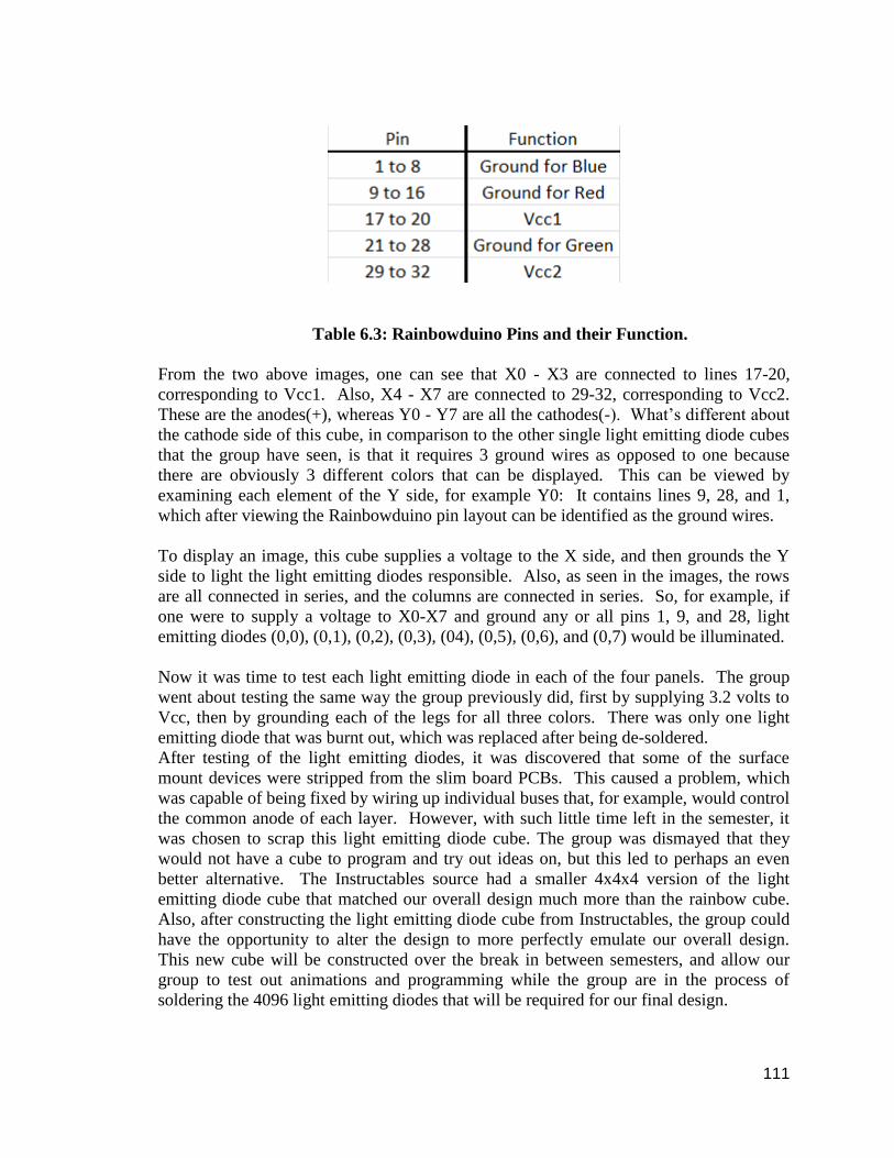
111
Table 6.3: Rainbowduino Pins and their Function.
From the two above images, one can see that X0 - X3 are connected to lines 17-20,
corresponding to Vcc1. Also, X4 - X7 are connected to 29-32, corresponding to Vcc2.
These are the anodes(+), whereas Y0 - Y7 are all the cathodes(-). What’s different about
the cathode side of this cube, in comparison to the other single light emitting diode cubes
that the group have seen, is that it requires 3 ground wires as opposed to one because
there are obviously 3 different colors that can be displayed. This can be viewed by
examining each element of the Y side, for example Y0: It contains lines 9, 28, and 1,
which after viewing the Rainbowduino pin layout can be identified as the ground wires.
To display an image, this cube supplies a voltage to the X side, and then grounds the Y
side to light the light emitting diodes responsible. Also, as seen in the images, the rows
are all connected in series, and the columns are connected in series. So, for example, if
one were to supply a voltage to X0-X7 and ground any or all pins 1, 9, and 28, light
emitting diodes (0,0), (0,1), (0,2), (0,3), (04), (0,5), (0,6), and (0,7) would be illuminated.
Now it was time to test each light emitting diode in each of the four panels. The group
went about testing the same way the group previously did, first by supplying 3.2 volts to
Vcc, then by grounding each of the legs for all three colors. There was only one light
emitting diode that was burnt out, which was replaced after being de-soldered.
After testing of the light emitting diodes, it was discovered that some of the surface
mount devices were stripped from the slim board PCBs. This caused a problem, which
was capable of being fixed by wiring up individual buses that, for example, would control
the common anode of each layer. However, with such little time left in the semester, it
was chosen to scrap this light emitting diode cube. The group was dismayed that they
would not have a cube to program and try out ideas on, but this led to perhaps an even
better alternative. The Instructables source had a smaller 4x4x4 version of the light
emitting diode cube that matched our overall design much more than the rainbow cube.
Also, after constructing the light emitting diode cube from Instructables, the group could
have the opportunity to alter the design to more perfectly emulate our overall design.
This new cube will be constructed over the break in between semesters, and allow our
group to test out animations and programming while the group are in the process of
soldering the 4096 light emitting diodes that will be required for our final design.

112
In figure 6.16, when viewed for the first time, was utterly confusing. It was not until the
research in section 3.1.4 that the true power of the above method of wiring the layers was
recognized. In the above image, each layer has a common anode which supplies the
voltage Vcc. Next, three buses control the red, green, and blue light emitting diodes.
Now, what was unrealized was the power of grounding more than one light emitting
diode at a time, as well as toggling the intensity of the light emitting diodes to generate a
multitude of colors.
Figure 6.16: How the Rainbowduino is connected to the Layers. Pending permission from Seedstudios [3]
6.5.3 Programming From the testing of the prototype's code the group learned that they would need to
continuously send signals to the light emitting diodes in a manner that makes use of the
persistence of light. Our light emitting diode buffer will have to be sent in pieces that will
correspond to the various sections of light emitting diodes that can be lit up
simultaneously. This will depend on how the light emitting diodes are wired. Once the
group knows that they can program the buffer to be sent in chunks that correspond to a
certain set of light emitting diodes. Then cycle through all the section quickly to create
the illusion that they are all on. Whether an light emitting diode gets turned on or not will
of course depend on what is inside of the buffer when it is being sent.
The way the Rainbowduino code accomplished this task was with an interrupt service
routine(ISR) that went off after a specific time interval. Every time this ISR is tripped it
would send the data from the light emitting diode buffer to the light emitting diode
drivers.
The group also learned that they should use a header file to define port names to make it
easier to program around them. The Rainbow Arduinos' header file contained the various

113
ports that would be used by the Atmega 328 inside the Rainbowduino to communicate
with its light emitting diode drivers. This also makes the code more portable as the group
only needed to change the definition of the ports in one place rather than all over our
code.
The way the Rainbowduino code kept track of its pixels is by using a 2D array and
mapping the 3D points to that grid. This was done because the program is designed to
interface with not only a cube but also with a 2D matrix of light emitting diodes. The 2D
matrix of light emitting diodes simply used the 2D array to interact with its light emitting
diodes and the cube had some transformation matrices. For our code the group will not
need such a roundabout method as they will only be interfacing with a cube. They won't
need to represent the cube on a 2D matrix. The group will probably use a 3D matrix to
represent the light emitting diode cube and just place values directly into that instead of
using a matrix transform.
6.6 Homemade 4x4x4 Prototype LED Cube It was decided that it would be in our group's best interests to construct an light emitting
diode cube that more closely resembled the one in which the group would be creating for
our final project. Below is a short summary of the cube the group intends to erect
including cost, design detail, and the components the group plans to integrate to test on a
small scale.
6.6.1 Component List and Cost Below is a price list for the components purchased for the prototype cube. As seen in
table 6.4, some components like the transistors were purchased from RadioShack, leading
to an increased cost for these relatively inexpensive components. Table 6.4 details the
components and their costs.

114
Table 6.4: Price List for 4x4x4 light emitting diode Cube
It was relatively easy to attain all the components in question. Online retailers had plenty
of stock for all that was needed and everything else was obtained from RadioShack and
Sky Craft.
6.6.2 Summary of Design Detail The 4x4x4 light emitting diode cube from Instructables is by the same author that
designed the 8x8x8 one that is explained in detail in an earlier part of this document.
Some design features that the group will be changing are adopted from the NTE cube
detailed in the same section as the Instructables one. For instance, the group will
construct the cube in vertical sheets as opposed to horizontal layers. This will made
constructing the cube easier and mimic the design the group plans to use in the final
implementation of the cube.
Another major design the group plans to implement is the use of tri-color light emitting
diodes as opposed to the single color ones used in the Instructables reference. This
should not be too complicated, and will come in use during the programming aspect of
the cube. There is much source code available for the cube that the group is building, so
only minor changes will need to be made initially to the code.

115
6.6.3 Advanced Implementation Our group plans to expand upon the cube described by Instructables by implementing our
own components into the design. For instance, the group will be using light emitting
diode drivers in our final implementation. The way that data is loaded to the cube using
the TLC is far different from the method of decoding and using da d-latch array, but it is
more efficient at programming advanced images. It would be beneficial to get the TLC
light emitting diode driver working on a small scale prior to hooking up our enormous
final designing and trying to figure out how to make it work.
Another aspect, even more major than the light emitting diode drivers, is the use of the
LM3S microcontroller. The group is using the atmega16 to design the cube above
because there is already a variety of source code and animations available. However, the
group needs to get used to programming with the Stellaris and find out how to use it to
control our cube. This will give us great insight into the final design and give us a jump
start on figuring out just how to make the cube work.

116
7.0 Administrative Content With the design fully outlined it falls to the group to fully describe themselves. Along
will describing themselves the group will also lay down the timeline for which the project
will be completed by laying out when everything should be completed. Finally, the group
will lay out exactly how much they plan to spend on all of the items and list a final
budget.
7.1 Milestones

117
7.2 Budget and Finances
Available Budget: $800
SeedStudio kit
Price: $54.90
Available at Seedstudio.com
Description: This kit includes parts to construct a 4x4x4 light emitting diode cube. All the
light emitting diodes, PCBs, resistors, capacitors, and various other components
necessary for operation are available. The only thing that is necessary for operation that
was not included in the kit is the Rainbow Arduino for the necessary drivers and
connections.
Rainbowduino Light Emitting Diode driver platform – Atmega 328
Price: $24.90
Available at Seedstudio.com
Features:
● Provides 2 x 16 pin header
● Can drive 4x4x4 RGB light emitting diode Cube or Can drive 8x8 RGB light
emitting diode Matrix
● Constant current of 20.8mA LED driver
TI Stellaris Microcontroller – LM3S8962
Available at TI.com
Features: Features listed in 3.2.3.1
Price: $0.00
RGB LEDs
Price: $0.17/ LED
Features: LEDs will have 3 cathode wires and one anode ground wire. Each cathode wire
corresponds to a single red, green, or blue diode. When voltage is supplied to the anode
wire and the cathode is grounded at the same time, this causes the LED to illuminate.
When voltage is supplied to a single anode and multiple cathodes are grounded, this
allows for the use of a wide array of colors.
TLC5941 LED Driver
Available at TI.com
Description: Features listed in 3.2.1.2
Price: $0.00
Acrylic Available at Home Depot
Price: $1 / 6 feet
Description: This will feature the acrylic base and the rods to create the rig

118
Laptops and Computers
Price: $0.00
Description: the group will use the computers in the Senior Design Lab; the Laptops are
the users’ property.
Power Supply
Price: $0.00
Description: With multiple power supplies available, the group will have at hand a 7V
and a 10V psu.
Resistors
Price: $0.00
Available at Digikey.com
Features: The resistors will range from 100 to 200 Ohms.
Transistors
Available at Digikey.com
Price: $0.17
Features: It is unsure whether MOSFETs or BJTs will be used to drive the voltage
supplied to the layers. More testing will need to be done on the prototype cube in the
following weeks.
Capacitors
Available at Digikey.com
Price: $0.03
Features: The capacitors will range with various capacitance.

119
Summary of Expenses
Part Price Quantity Total Price
SeedStudio Kit $54.90 1 $54.90
Rainbowduino $24.90 1 $24.90
TI TLC5941 $0.00 3 $0.00
RGB light emitting diodes $0.10 4200 $420.00
TLC59711 $0.00 3 $0.00
Acrylic Rods $1 / 6ft 256 Rods 768 Ft. $128
Laptop/Computers $0.00 4 $0.00
Power Supply $0.00 1 $0.00
Resistors $0.00 500 $0.00
Transistors $0.17 16 $2.72
Capacitors $0.03 200 $6.00
Total $6 36.52
Table 7.2: Budget and Parts
7.3 Group Member Bios The group is made up of 4 members. The group contains two electrical engineers; Joseph
Clark and Michael Alberts are seniors in Electrical Engineering and plan to graduate in
August 2012. Isaiah Walker and Arnold Li are both seniors in Computer Engineering
who also hope to graduate in August 2012.
7.3.1 Joseph Clark Joseph Clark was born January 6th 1986, in Saratoga Springs New York. He spent most
of his childhood in Titusville Florida, but also lived in Glenville New York, Austin
Texas, and Niceville Florida where he would graduate from Niceville High School. In
high school he took a vast array of classes trying to find what interested him the most.
During high school he took advanced digital design classes, college level programming
classes, college level accounting classes, and college level foreign language classes
alongside his standard academic course load.
During his tenure in high school he was involved in a number of extracurricular
activities. The most significant activity that he participated in was the Forensics Team.

120
While on the Forensics team he competed in the debate events of public forum, Lincoln-
Douglass, and policy debate. He maintained a winning record in all three of the events
and was invited to multiple national event to compete, and winning multiple top speaker
awards. He also served as a special advisor of digital media for the school year book.
During this time he provided photo manipulation and page layout services. In high school
he also co-founded a multicultural media club. In his time they would view movies and
television shows from England, France, Japan, China, and many other countries from
around the world.
After graduating from Niceville High School Joseph did not immediately return to
school. However in 2008 he returned to school by enrolling at Valencia Community
College. While at Valencia, Joseph competed in the brain bowl academic team for 2
years. Joseph was a part of a four person team and was in charge of answering question
about science and math for his team. Josephs’ team was invited to the national
competition. Joseph Graduated from Valencia Community College in 2008 and was
accepted to the University of Central Florida electrical engineering program.
While attending the University of Central Florida Joseph became involved in
undergraduate research at the Center for Research and Education in Optics and Lasers.
Joseph worked for Dr. Peter Delfyette and was able to work on many projects and gain a
vast array new knowledge. His first project involved Allan Variance measurements.
Joseph wrote programs to automate the process and was involved in the purchase of an
automated test bed. Joseph also developed a base for holding a Vertical Cavity Surface
Emitting Laser. The base worked both as a platform to hold the laser and a heat sink. The
base would hold the Laser above a Printed Circuit Board. The printed circuit board was a
special design capable of handling a 5 GHz signal and performing impedance matching
from 50 to 90 ohms. Joseph hopes he can bring some of these experiences to the senior
design project to aid the group.
Joseph plans to graduate in August 2102. He has plans to work in the field of optics. He
currently hopes to work for the Harris Center for Optics excellence where he will
continue his learning in the field of optics. He also helps to continue his education at The
University of Central Florida at the Center for Research and Education in Optics and
Lasers. Joseph has hopes of earning his Ph.D.
7.3.2 Michael Alberts Michael Alberts was born in Saint Petersburg Florida on December 20th, 1988. He
attended Lakewood High School where he was enrolled in the Center for Advanced
Technologies (CAT); a magnet program geared to ready students for college and provide
them with technical skills that they would require. While attending the CAT program
he took classes pertaining to science, math, and programming. Some of the classes that
prepared him the most for college included physics, calculus, Java, and C programming.
During his junior year he was inducted into the National Honor Society and maintained
this status all the way until the time of graduation. He feels that the NHS was beneficial
to his success in both high school and college, because he felt the need to maintain the

121
level of prestige that was awarded to him, as well as uphold the standards that the NHS
enforced.
Besides high school academics, Michael was on the Lakewood varsity baseball team
from the time he was a freshman until the time of graduation. During his four years of
playing, he won numerous awards granted by both the school and during tournaments
that were held throughout the state, and had the privilege of being the captain of the team
his senior year. The highlight of his high school baseball career was when he was asked
to play on the Pinellas county all-star team during his senior year, being only one of
twenty athletes from the area chosen. He believes that his baseball career is very
beneficial to his professional success because it taught him the importance of teamwork,
the qualities of being a leader, and seeing first hand that hard work pays off.
Michael began attending the University of Central Florida the summer directly following
graduation from Lakewood high school in 2007. He was enrolled in the College of
Engineering where he planned on attaining his bachelor’s degree in electrical
engineering. During his career at UCF, Michael completed his engineering classes, all
the while maintaining a 3.0+ GPA, thus allowing his to keep his bright futures
scholarship the entirety of his attendance. While engineering is his main focus, he enjoys
the programming aspect as well. Taking an object oriented programming class in Java as
a technical elective, and also taking computer science I just for the understanding of the
material, Michael realizes the importance of programming in electrical engineering,
which led him to enroll in a hardware/software co-design tech elective, as well as a
computer architecture tech elective.
Michael believes that he is an important asset to the group because of his problem solving
skills and his ability to dedicate himself to learning any subject he needs to. He enjoyed
computer science mainly because of the problem solving aspect of the class, and often
dedicated hours of continuous work to class projects due to the sheer enjoyment of
solving the given problem. He is also able to educate himself without the need of a
professor or a guide. This quality is a necessity to any engineer, and one of the main
focuses of senior design.
Aside from his focus on academics, Michael enjoys playing numerous intramural sports
for UCF, including basketball, volleyball, flag football, and floor hockey. In his spare
time he also enjoys writing small android applications, cooking, and reading. Michael is
set to graduate in August 2012, and will be pursuing a job in the engineering field.
7.3.3 Isaiah Walker Isaiah Renaldo Walker is a computer engineering major. He comes from Pembroke Pines
in Miramar, which is north of Miami. His hobbies include playing video games, listening
to music, playing bass guitar and programming. He went to Everglades High School for
ninth and tenth grade then went into College Academy for the remainder of my high
school career. College academy was a program in which the last two years of high school
are done at Broward College and high school classes are taken alongside college level
classes with it all counting as college credit. Through this program he not only graduated
high school but he also got his A. A. Degree.

122
Throughout his college career most of his focus has been on the software side of
computer engineering. His electives have focused on learning more about programming
and also some topics on machine learning. After he gets his Bachelor’s degree he wants
to continue his education by going into the Master’s program at the Florida Interactive
Entertainment Academy to go into game design. He would like to go work for one of the
major video game companies after his education is over. He would love to one day be a
programmer for Blizzard or Nintendo.
He has worked on some other programming projects, both for classes and outside of
classes. These projects mostly focused on Java as the main language. He has written
some code for a small android application for a group project. The application used GPS
to search for coupons near your location that other people have submitted. It did not go
on the market but the group did get it to work with multiple phones. He also wrote most
of the base code for a vertical scrolling shooter game on the Android platform. He wrote
the code for the ship that flies through the levels as well as the code for scrolling through
the level and spawning enemies. As for his experience in C and C++, he has written
several things on his own that showcases my skills in those languages. He has written a
text based letter scrambler and even a small maze game using a free game software
development kit. Most of his programming does involve working with games since that is
what he wants to pursue in my career after college. Despite that being his focus he will
still be able to help with the programming of the cube's software.
He does not have much experience working with microcontrollers but he will try to learn
quickly to be able to assist in helping make this project work. He has always been very
good at figuring out software related problems when they occur and quickly find
solutions. The biggest challenge he shall face will be learning to work with the limited
space and speed of a micro-controller as compared to that of the more powerful CPUs
found in a desktop computer where he would normally do my programming. The micro-
controller may also have some limitations in its implementation of C/C++ that he may
have to make adjustments to. The micro-controller may not be able to handle floating
point math or certain complex math functions such as sine and square rooting. This
means that some of my normal programming habits will have to alter to fit in with the
micro-controller's environment.
7.3.4 Arnold Li My name is Arnold Li. He was born on January 13, 1990 in Miami, Florida. Arnold
graduated from Michael M. Krop Senior High School and cherished every moment of it.
He took a moderate amount of Advance Placement classes and passed them for college
credits and attended many clubs. Compared to college, there were classes that made high
school classes look like a cake walk and there were classes that will literally blow his
mind away. Arnold takes every class seriously and tries to his utmost ability to pass with
flying colors. There may be some topics he may be weak in, but he makes sure he has
some help to facilitate his learning.

123
When Arnold has free time, he enjoys playing video games with his friends. Back in
freshman year, he and his friends would sign up to play first person shooters
professionally. They would practice by playing normal games in public rooms or versus
each other. They didn’t mind if it was consoles like Xbox 360, PlayStation 3, or PC, but
it was easier to get together playing on the PC. Back at home Arnold enjoys fishing,
football, basketball, ultimate Frisbee, practicing guitar, and eating. He gets in touch with
his friends to watch football or watch the Miami Heat for dinner and have a fun time,
unless they lose.
If it wasn’t for the expensive costs of a plane ticket, Arnold probably would have traveled
more often. He has traveled to many parts of the United States, cruised out in the
Caribbean, and flew to the other side of the world to China. He enjoys the cultural
experiences and the food that comes with it. He hopes to venture to other parts of the
world and maybe learn a language or two.
During his years in University of Central Florida, the first couple years were probably the
most stressful and difficult. Taking five classes is never an easy task, but helped him
realize that he have to put some effort and time if he needed to pass. Not only that, the
best way to approach a class is probably to have friends to study with and learn together.
When Arnold enrolled in a world history class with all of his roommates and friends, the
group expected to be an easy A. This class includes online quizzes with two attempts, an
online midterm, and in-class final. During the whole process all of them scored 100s
consecutively on all their quizzes, aced the midterm, and passed the final with relative
ease. It truly was an easy A.
Arnold plans to graduate this August with a Bachelor in Computer Engineering. There
was never a semester in college where he probably wasn’t programming or sleeping.
Arnold hopes to continue to program in the working field. When Arnold signed up for
the major, he did not have prior knowledge of programming nor electronics. This is one
field that will continue to grow. Arnold is experienced in many types of programming
languages, an understanding how to fix and make computers, and with this project, have
a better understanding with microcontrollers with software.
7.4 Division of Labor There are two major parts to this project, hardware and software. The hardware aspect of
the project will be mainly handled by Mike Alberts and Joseph Clark. They will handle
the soldering and placement of the components on the printed circuit board. They will
also be responsible for making the jig that they will use to assist them in the soldering of
the light emitting diodes. The software aspect of the project will be handled by Arnold Li
and Isaiah Walker. They will handle writing the code that controls the hardware to make
the light emitting diodes light up according to the various animations. They will also
handle creating the animations for the cube to use.

124
8.0 Conclusion
In conclusion, the group feels that they have a flawless understand of how an LED cube
works, as well as a concrete plan on how the cube will be built. It was ironic that this
was chosen as the final project, because when the group set out to try to decide on a final
project they had originally intended to make a function one as opposed to one that is
strictly for viewing pleasure. The LED cube was chosen due to viewing a video online
of a cube and the animations it could perform. The group was immediately impressed
and decided that the LED cube was going to be what they created as their senior design
project.
From the amount of research that was done, the group was able to incorporate many
different elements of design from multiple cubes, picking out the features that would
benefit their design and ensure a professional, well-built final project. The group will
begin working on prototype LED cube that is planned to be completed before the start of
the next semester with the hopes of gaining insight on how it will be to build and test the
final design. This will provide for not only testing of the construction method, but also a
means to test the code for the animations and provide a way to test the controller that the
group will be using.
The expectation is that they LEDs will take at least 30 hours or more to completely solder
into a single cube, and then the testing to begin. It is unsure as to how long the testing
phase will be, but it is planned that code will already be written and the control layout
will be finalized at the time the LEDs are soldered into a cube so that this phase proceeds
smoothly and the project is completed early on in the semester. After the completion of a
cube that performs standard animation and three dimensional images, whatever is left of
the remaining time will be spent working on providing more animations, a graphical user
interface, and completely debugging the system of any errors that could shorten the life
of the cube.
The group also plans on entering the Texas Instruments design contest that is being held.
The design contest is early in time than the deadline for the cube, so this event will
provide motivation for the group to complete their final project in a timely manner. One
of the requirements for the competition is to use at least three Texas Instruments analog
parts in the design of the project, which is why the group has planned on using so many
components acquired from Texas Instruments.
The group is also very pleased that their design will be on display of the Harris
Engineering Corporation building. This honor has motivated them to build the best
possible cube given the amount of time they have. When presented with the option of
choosing single color or RGB LEDs, the group chose to select the RGB LEDs due to the
fact that the tri color displays are far superior to the single color. The amount of time
required to construct a cube from RGB is far more than that of the single color, but the
RGB will provide for far more impressive animations and displays. Also, the decision to

125
use LED drivers was fueled by this. The use of LED drivers significantly enhances the
performance of the cube, providing for such functions as pulse width modulation, making
sure all the LEDs shine at the same luminosity, and taking full control over the spectrum
of colors that the cube can display.
Finally, the group is pleased that they chose to build an LED cube. The amount of work
that must be done to solder is not the most appealing aspect of the project, but they
hardware and software code sign that has to be implemented is a beneficial aspect the
members. Great amounts of thought have been put into how the microcontroller will
control the cube, and how it will interact with the different components that make up the
project. There are many factors that have to be investigated such as operating frequency,
general purpose input/output pin usage, voltage required to power the entire setup, how to
drive the LEDs, and the exact layout of the printed circuit board to save space and
provide for the best configuration of the elements of the design.

126
9.0 References "3D light emitting diode Cube Kit." Nuts and Volts. N.p., n.d. Web. 16 Feb 2012.
<http://store.nutsvolts.com/product.php?productid=17052&cat=341&bestseller=Y>.
"4Cube USB Kit." Hypnocube. N.p., n.d. Web. 16 Feb 2012.
<http://hypnocube.com/products/4cube-all/4cube-usb-kit/>.
Chr. "Led Cube 8x8x8." Instructables. N.p., n.d. Web. 2 Feb 2012.
<http://www.instructables.com/id/Led-Cube-8x8x8/?ALLSTEPS>.
"light emitting diode Cube Kit." Picprojects. N.p., n.d. Web. 16 Feb 2012.
<http://picprojects.biz/shop/article_555FSK/light emitting diode-Cube-Kit-
#555FSK.html?shop_param=cid=2&aid=555FSK&>.
"LT3754 ." Linear Technology. Linear Technology, n.d. Web. 11 Mar 2012.
<http://www.linear.com/product/LT3754>.
Phil. "Charlieplexing LEDs- The Theory." Instructables. 27 Aug 2008, n.d. Web. 20 Feb
2012. <http://www.instructables.com/id/Charlieplexing-LEDs--The-
theory/?ALLSTEPS>.
"qubeled." qubeled. N.p., n.d. Web. 16 Feb 2012. <http://qubeled.com/
"Rainbow Cube." seeedwiki. N.p., 15 March 2012. Web. 16 Fwb 2012.
<http://seeedstudio.com/wiki/Rainbow_Cube>.
Reitzfeld, Wesley, Sachit Bakshi, Shatrovoy Oleg, and Elaine Uy. "3D light emitting
diode Cube Display." BU Electrical & Computer Engineering. N.p., n.d. Web. 11 Apr
2012. <http://www.bu.edu/ece/undergraduate/senior-design-project/senior-design-
projects-2008/3d-led-cube-display/>.
Shulze, Nick. "RGB light emitting diode Cube." How Not to Engineer. N.p., 06 April
2012. Web. 18 Apr 2012. <http://www.hownottoengineer.com/projects/rgb-led-
cube.html>.
Texas Instruments. Texas Instruments, n.d. Web. 11 Mar 2012. <http://www.ti.com/>.
LED Frequently Asked Questions. BeteLED.com Web. 20 April 2012.
<http://www.betaled.com/us-en/LEDEducation/LEDFAQ.aspx#16>

127
Appendix Appendix A Copyright Permissions [1] Boston University
[2] Quebled
[3] Pending Permission -Seedstudios
Permission Pending from Seedstudios
[4] Picprojects

128
[5] Hypnocube
[6] Pending Permission - Nuts and volts
Permissions Pending from Nuts and volts.
[7]Instructables 8x8x8
[8] Nick Schulze - HNTE

129
[9] Instructables Charlieplexing