DURAG D-R 290 OPACITY ANALYZER 1. Measuring … · DURAG D-R 290 OPACITY ANALYZER Before proceeding...
43
DURAG D-R 290 OPACITY ANALYZER Before proceeding to do a manual calibration, on any of the following equipment, please familiarize yourself with the manual for each piece of equipment that you will be working on. 1. Measuring Ranges a. The D-R 290 has two analog measured value outputs. Each output has two freely selectable extinction or opacity measuring ranges. In the basic setting the measuring ranges are assigned to the two measured value outputs. The measuring ranges can be set independently of each other. b. The outputs can be switched to measuring range 2 by activating the relevant status input. For output 1, the jumper should be set between terminal X2 11 and 12; output 2 gets the jumper between terminal X2 31 and 32. The outputs can be set independently of each other to opacity or extinction. 2. Integration Times
Transcript of DURAG D-R 290 OPACITY ANALYZER 1. Measuring … · DURAG D-R 290 OPACITY ANALYZER Before proceeding...

DURAG D-R 290 OPACITY ANALYZER Before proceeding to do a manual calibration, on any of the following equipment, please familiarize yourself with the manual for each piece of equipment that you will be working on.
1. Measuring Ranges
a. The D-R 290 has two analog measured value outputs. Each
output has two freely selectable extinction or opacity measuring
ranges. In the basic setting the measuring ranges are assigned
to the two measured value outputs. The measuring ranges can
be set independently of each other.
b. The outputs can be switched to measuring range 2 by
activating the relevant status input. For output 1, the jumper
should be set between terminal X2 11 and 12; output 2 gets the
jumper between terminal X2 31 and 32. The outputs can be set
independently of each other to opacity or extinction.
2. Integration Times
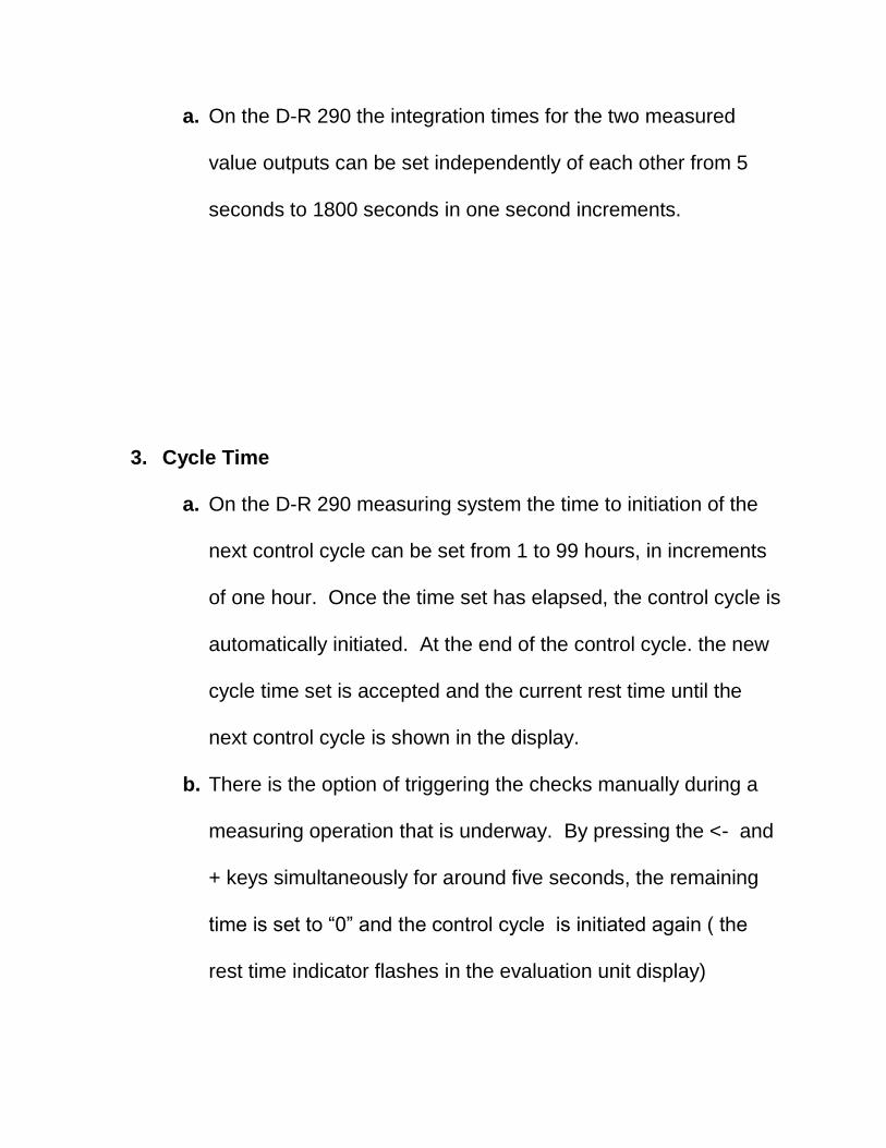
a. On the D-R 290 the integration times for the two measured
value outputs can be set independently of each other from 5
seconds to 1800 seconds in one second increments.
3. Cycle Time
a. On the D-R 290 measuring system the time to initiation of the
next control cycle can be set from 1 to 99 hours, in increments
of one hour. Once the time set has elapsed, the control cycle is
automatically initiated. At the end of the control cycle. the new
cycle time set is accepted and the current rest time until the
next control cycle is shown in the display.
b. There is the option of triggering the checks manually during a
measuring operation that is underway. By pressing the <- and
+ keys simultaneously for around five seconds, the remaining
time is set to “0” and the control cycle is initiated again ( the
rest time indicator flashes in the evaluation unit display)

c. The D-R 290 AW2 evaluation unit has a status input for the
control cycle.
i. Open: Control cycle is automatically triggered as
described.
ii. Closed: Control cycle is not automatically executed, only
manually (no rest time display)
iii. On Opening: Control cycle is triggered (initiated) as
described.
4. Contamination Alarm
a. On the D-R 290 the threshold of the degree of contamination
(“Window Alarm”) after which a contamination alarm is sent can
be set in 0.1% increments. The adjustment range is 0 to 9.9%.
On the setting 0.0% the contamination alarm is disabled.
b. If during the contamination check, the measured degree of
contamination exceeds the specified percentage, then the
message “**ERROR 001**” appears in the display. After a
delay of around 10 seconds a fault message is sent via the
“Fault” relay output.

5. Limit Values
a. There are two adjustable limit value contacts available. In the
basic setting the limit values are assigned to the two measured
value outputs. The limit values can be set independently in
increments of 0.1 mA over the entire measuring range in each
case. If the limit values are exceeded, the relevant relay
contact operates for the period that this occurs.
6. Linearity Check
a. Control mode is for a linearity check in accordance with the
EPA requirements. The linearity measurement is performed in
the measuring range set for output 1. Once control mode has
been selected, a contamination correction is performed for
around 10 seconds, if necessary by pressing the “STO” key,
and the display is thus brought to 4 mA.

7. Zero Point Check
a. On the D-R 290 there is a zero point check in the set measuring
range at the start of the control cycle for 1 hour and 30 minutes.
Once the zero point reflector has been tilted into its position on
the measuring head, the output current increases to 4 mA.
There is also the option of a manual prompt for zero point
control.
8. Contamination Check
a. On the D-R 290 in the control cycle after the zero point check
for 90 seconds there is a contamination check in the set
measuring range. The contamination on the optical interfaces
is measured and displayed. The measurement results of the
subsequent measurements are corrected by the magnitude of
the contamination measured. If, during the contamination
check, the measured degree of contamination exceeds the
specified percentage, then a fault message is output and the

message “**ERROR 001**” appears in the display. There is
also the option of a manual prompt for contamination.
9. Span Check
a. In the control cycle for approximately 90 seconds, after the
contamination check there is a span check. By means of a step
motor, a mesh filter is tilted into the path of the receiver bear.
The reference value (span) should be reproducible on every
span check. There is also the option of a manual prompt for
the span reference value.
10. Stack Correction Factor
a. If the measurement of the D-R 290 is to be evaluated as if the
measuring light crosses the measuring path only once at the
stack exit (in accordance with the EPA), stack correction factor
L2/L1 should be set. The correction factor set is effective in the
opacity measuring ranges of the two measured value outputs.
i. L1: diameter of the stack at the measured point
ii. L2: diameter at the stack exit

b. When selecting the stack correction factor this is also output as
current. 0.5 to 2.9 corresponds to 4.0 mA to 20 mA.
c. The standard setting for the stack correction factor is 1. This
setting results in opacity being displayed as if the measuring
light crosses the measuring path only once at the point of
measurement.
11. Recording of the measured Values
a. The current value of the measurement is output by the D-R 290
as an analog current signal. The statutory requirements require
continuous recording of the measured values. For recording, a
logger (0-20 mA) with a recording width of at least 100 mm is
suitable, equivalent to quality class 1.0 to VDE 0410. The zero
point of the display is at 20% (4 mA live zero) of the recording
scale.
b. The measured values and status signals output can however
also be processed by a downstream emissions calculator.

MODEL 922 AMETEK SO2/NOx ANALYZER BEFORE PROCEEDING TO DO A MANUAL CALIBRATION, OF ANY OF THE FOLLOWING EQUIPMENT, PLEASE FAMILIARIZE YOURSELF WITH THE MANUAL FOR EACH PIECE OF EQUIPMENT THAT YOU WILL BE WORKING ON.
CALIBRATION OF THE CEM CO AND SO2 /NOX ANALYZERS When doing a manual calibration on these instruments requires the admission of calibration gasses through the PROBE CAL switch located on the gas conditioner panel. When calibrating the zero on the so2 or Nox analyzer, remember that they will both be calibrated at the same time. TURN ON THE PROBE CAL SWITCH-BY ROCKING IT TO THE RIGHT TURN ON THE HI SV1 SWITCH- BY ROCKING IT TO THE RIGHT THIS WILL ADMIT HI O2 CALIBRATION GAS TO THE PROBE AND BOTH CO AND SO2/ Nox INSTUMENTS. AFTER 10 MINUTES HAS ELAPSED;
1. ON THE SO2 AND Nox ANALYZER 2. PRESS THE F6 KEY 3. PRESS THE”. “ KEY (THREE TIMES) 4. PRESS THE ENTER KEY 5. PRESS THE F2 KEY 6. PRES THE 0 KEY 7. PRESS THE ENTER KEY 8. THE INSTRUMENT WILL COUNT DOWN FROM 30 TO 0 AND
CHANGE THE VAUES TO 0 ON BOTH INSTUMENTS AT THE SAME TIME.
THE INSTRUMENTS SHOULD DISPLAY CAL SO2 Nox 0 0

TO CALIBRATE THE SPAN VLUES FOR THE nox AND SO2 ANALYZERS When calibrating the span on theSO2 or Nox analyzer leave the probe cal switch in the on position – shut off the zero o2 SV1 and turn on the SPAN1 switch SV3 by rocking the switch to the right. After ten minutes has elapsed; And you still have a stable reading on the SO2 and Nox analyzer Press the F6 key Press the (.) key (THREE TIMES) Press the enter key continue with F2 1 enter (SO2 span) Analyzer will countdown F2 3 enter (Nox span) Analyzer will countdown from 30 OPTIONAL DATA ENTRY to change span values in the instrument after changing calibration gas bottles On the SO2 analyzer only Press F4 1 key The display will read; CAL CONC 1 (example 428.00 PPM) Press DEL key Enter the new value with the number key (example 431.31) Press the ENTER key Press the ESC; key to go back into the monitoring mode

MODEL 600D NDIR ANALYZER Before proceeding to do a manual calibration, on any of the following equipment, please familiarize yourself with the manual for each piece of equipment that you will be working on. TO CALIBRATE THE SPAN VALUES FOR THE CO ANALYZER After ten minutes has elapsed; And you have a stable reading on the CO analyzer Press the MENU push button Press the DOWN ARROW push button (three times) Display shows [“>calibration”] with the> arrow in front of calibration If not move the up/down ^v arrow button until it does Press the ENTER button The display will show > calibrate zero
calibrate CO Press the ENTER push button Display will read; CO PPM XXX RANGE 1000 SET TO xx898.00 Using the right arrow > PUSH BUTTON select the digit you want to replace Then using the ^v up/down arrows to select the correct number. When you get the calibration gas value displayed press the ENTER push button Then push the RUN push button to return to monitoring mode. Turn off the PROBE CAL switch and also the SPAN 1SV3 switch. Turn on the PURGE SWITCH for one minute then turn it off again. CALIBRATION COMPLETE

BRAND-GAUS MODEL 4705 OXYGEN ANALYZER
Before proceeding to do a manual calibration , on any of the following equipment, please familiarize yourself with the manual for each piece of equipment that you will be working on. After installation and at least a 1- hour warm up period, the instrument can be calibrated via the following procedure. The Brand-Gaus oxygen analyzer calibrations are generally very stable. If the calibration appears to have drifted significantly, or requires frequent adjustment, do not recalibrate the unit. Check for analyzer malfunction and/or check the sample delivery system for leaks or other problems. 1. Low Calibration
a. Flow low calibration gas (typically zero) through the sample handling system and analyzer. Dry nitrogen or EPA protocol gas is recommended as a low calibration gas.
b. Wait approximately two minutes or until reading settles. c. Adjust the " low cal" potentiometer on the front panel until the display
reads the desired concentration (typically zero). 2. High Calibration:
a. Flow High calibration gas through the sample handling system and analyzer.
b. Wait approximately two minutes or until reading settles. c. Adjust the "high cal" potentiometer on front panel until the display
reads the desired concentration.


CEM EQUIPMENT SPARE PARTS LIST
HILLMAN POWER COMPANY
CO ANALYZER
(CO – CARULITE
SOLENOID #7368 (2)
FUSE 2 AMP SLO-BLO
NOX/SO2 ANALYZER
DRIERITE #L-07193-05
ACTIVATED CHARCOAL
5 MICRON FILTER ELEMENTS
CADMIUM LAMP 3300-2070
MAGNESIUM LAMP 100-0688
O-RING CAPPILARY #4800
4293 AIR DRYER COLUMN/RING 9212
OPACITY ANALYZER
LENS CLEANING CLOTHS/CLEANING SOLUTION
BLOWER FILTER #2222
O2 ANALYZER
SPARE ANALYZER
O2 SENSOR
PROBE
FILTER GASKETS
VITON O-RINGS
5 MICRON FILTER
EQUIPMENT EXTRA
VACCUME PUMP
PARASTALIC PUMP
NEOPRENE HOSE

OPERATIONS MANUAL
Number:
OM-121
Subject:
Boiler Start On Wood
Approved for Use by:
Plant Manager Signature
Current Issue:
Rev 0 (R0)
Issue Date:
Tbd
Page 1 OF 9
TABLE OF CONTENTS
SECTION TITLE PAGE
1. Purpose ....................................................................................... 2
2. Discussion ................................................................................... 2
3. Responsibilities ............................................................................ 2

HILLMAN POWER CO.
BOILER START ON WOOD
OM 121 Boiler Start On Wood 2 of 8 R0
1. PURPOSE
The purpose of this procedure is to define emergency response for hazardous materials spills, medical/fire/law enforcement, weather emergencies, and evacuation.
2. DISCUSSION
This procedure applies to all plant personnel, contractors, and others who may be on the plant site during a fire, chemical release/spill, medical emergency, tornado/severe storms, or a bomb threat.
3. RESPONSIBILITIES
A. The Plant Manager has overall responsibility for the development, revision, and implementation of this plan and for assigning the title and associated responsibilities of Emergency Coordinator to an employee to adequately cover all periods when the facility is occupied.
B. The Operations Manager is responsible for the execution of this plan. The Operations Manager is designated as the Facility Emergency Coordinator.
C. The Operations Manager is responsible for conducting fire and evacuation drills. The Operations Manager is responsible for ensuring the Fire Department is notified, if necessary, and coordinating a response to the incident as well as directing the evacuation according to this plan. The Operations Manager shall designate an evacuation coordinator if the emergency requires personnel to evacuate.
D. The Control Operator will act as the evacuation coordinator until relieved by management and shall account for all operation and maintenance (O & M) personnel on site.
E. The Control Operator shall maintain radio communication with the Control Operator and keep a head count of all evacuated plant and contract personnel in order to report the status to the Control Operator.
F. All personnel will be trained on their work areas regarding fire routes, exits, the location and use of emergency equipment,

HILLMAN POWER CO.
BOILER START ON WOOD
OM 121 Boiler Start On Wood 3 of 8 R0
and understanding and following this plan. All personnel who have contractors or visitors at the facility shall ensure that they are familiar with this plan.
WOOD LIGHT OFF
I. Scope / Purpose
A. This procedure establishes the requirements for boiler light off
at the Hillman Power Plant utilizing wood. The boiler will
initially be started using natural gas and then be switched to
wood firing per this procedure at approximately 500psi steam
pressure.
II. Procedure
A. The Plant tech is to verify that all equipment is clear and
operational prior to starting.

HILLMAN POWER CO.
BOILER START ON WOOD
OM 121 Boiler Start On Wood 4 of 8 R0
III. Fuel System
A. Walk the entire fuel system and verify that it is clear and ready
for operation.
B. Start the fuel system, check operation, and load the reclaimer.
C. Slide out the fuel shut off grates from the wood feeders and
energize the feeders.
D. Set the feeder local controls to “auto on”, with the voltage dial at
0.
IV. Combustion Air
A. Start the distributor (rotary) air damper (HIC-320).
B. Increase the furnace draft fan damper to approximately -1.5”
H20.
C. Close the forced draft fan damper (PCD-311)
D. Start the forced draft fan (HIC-307)
1. The fan bearing temps need to be at 60°f minimum prior
to starting.
2. Maintain the furnace draft at approximately -1.5” H20.
E. Close the distributor air damper (PCD-318), and the over fire air
damper (FCD-315).
F. Start the over fire air fan (HIC-355)
1. The bearing temps need to be at 60°f minimum prior to
starting.
HILLMAN POWER CO.
BOILER START ON WOOD
OM 121 Boiler Start On Wood 5 of 8 R0
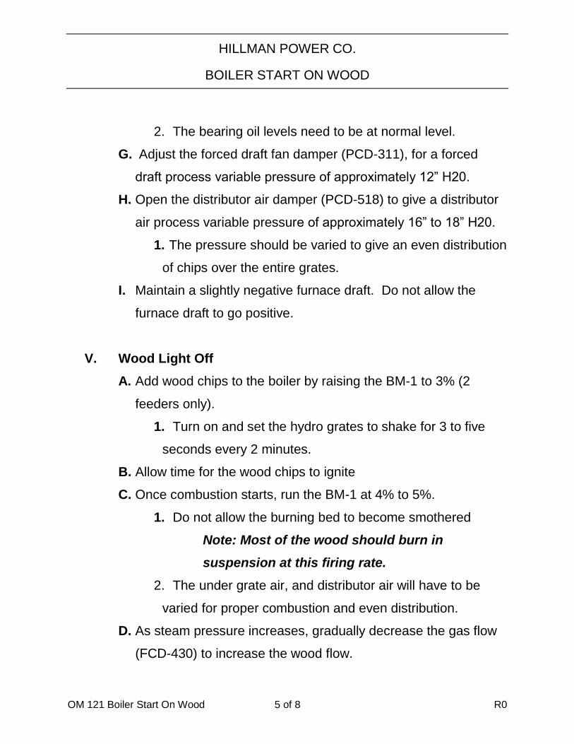
2. The bearing oil levels need to be at normal level.
G. Adjust the forced draft fan damper (PCD-311), for a forced
draft process variable pressure of approximately 12” H20.
H. Open the distributor air damper (PCD-518) to give a distributor
air process variable pressure of approximately 16” to 18” H20.
1. The pressure should be varied to give an even distribution
of chips over the entire grates.
I. Maintain a slightly negative furnace draft. Do not allow the
furnace draft to go positive.
V. Wood Light Off
A. Add wood chips to the boiler by raising the BM-1 to 3% (2
feeders only).
1. Turn on and set the hydro grates to shake for 3 to five
seconds every 2 minutes.
B. Allow time for the wood chips to ignite
C. Once combustion starts, run the BM-1 at 4% to 5%.
1. Do not allow the burning bed to become smothered
Note: Most of the wood should burn in
suspension at this firing rate.
2. The under grate air, and distributor air will have to be
varied for proper combustion and even distribution.
D. As steam pressure increases, gradually decrease the gas flow
(FCD-430) to increase the wood flow.

HILLMAN POWER CO.
BOILER START ON WOOD
OM 121 Boiler Start On Wood 6 of 8 R0
1. Gradually increase the wood firing rate (BM-1)as
required to a maximum of 5% prior to admitting steam to
the turbine.
2. Follow the attached warm up/cool down curve, do not
exceed this curve
3. Do not allow the secondary superheated inlet
temperature (TT-257) to exceed 750°f and/or the
secondary super heater outlet temperature to exceed
900°f.
E. Continue raising the steam pressure until the boiler reaches
operating temperature and pressure. Maintain between 750
and 850 psi steam pressure until the turbine is ready to be put
on the grid.
F. At 500 psi steam pressure open the attemperator and
desuperheater (TCV257) water supply root valve
Note: The control valve is to be closed prior to
opening the root valve.
VI. Generator Online
A. The boiler steam pressure is to be maintained at 750psi, when
admitting the steam to the turbine during the warm up.

HILLMAN POWER CO.
BOILER START ON WOOD
OM 121 Boiler Start On Wood 7 of 8 R0
1. As the wood firing rate is increased, adjust the
distributor air, under grate air, and over fire air as required
for combustion.
2. The super heater vent should be closed when the
turbine reaches 1500 RPM, or after the unit is online
3. Maintain the drum level as close to normal water level as
possible.
4. Adjust distributor air, under grate air, over fire air, and
the furnace draft as required for proper combustion.
B. If the steam pressure sags when putting the unit online,
increase the gas firing rate (FCV-430)
1. The combustion air fan (FCD-451) should be set at 45%
to 50%.
2. Do not exceed a gas firing rate of 60%
C. Synchronize the generator per Section 6 of the Procedure
Book.
D. After the unit is online, stabilize the boiler pressure,
temperature, water level, and wood firing rate; while decreasing
the gas flow.
E. After stabilization, secure the gas burner.
1. Close the gas control valve (FCV-430)
2. Stop the combustion air fan (HIC-429)
3. Close the combustion air fan damper (FCD-451)

HILLMAN POWER CO.
BOILER START ON WOOD
OM 121 Boiler Start On Wood 8 of 8 R0
4. Turn off the breaker in the flame safety panel, and push
the Reset Button on the side of the panel.
5. Close the burner manual gas valve and the two pilot
valves.
6. Adjust the hydro grate shake time to be as slow as
possible, while still maintaining an even burning bed of
chips on the grates.
OPERATIONS MANUAL
Number:
OM-519
Subject:
NOx REDUCTION SYSTEM
Approved for Use by:
Plant Manager Signature
Current Issue:
Rev 0 (R0)
Issue Date:
Tbd
Page 1 OF 8
TABLE OF CONTENTS
SECTION TITLE PAGE
1. Purpose ........................................................................................ 2
2. Discussion .................................................................................... 2
3. Responsibilities ............................................................................ 2
4. Procedure .................................................................................... 3

HILLMAN POWER COMPANY
NOx REDUCTION SYSTEM
1. PURPOSE
The purpose of these procedures is to provide a guideline to the general operations of the equipment at Hillman Power Plant. These procedures should be read and understood by all operators. It is mandatory that all employees adhere to these procedures for the safe operation of the equipment. These procedures should be used in conjunction with the applicable maintenance manuals, operation manuals, vendor manuals and standard power plant practices.
2. DISCUSSION
Prior to engaging any system, it is important to verify that all connections and associated apparatus are installed properly to assure the system performs correctly, efficiently, and safely. Remove all tools and other debris away from the system before starting.
3. RESPONSIBILITIES
A. The Plant Manager has overall responsibility for the development, revision, and implementation of these procedures.
B. The Operations Manager and the Maintenance Supervisor are responsible for the execution of this procedure.
C. The Control Room operator has responsibility to ensure these procedures are followed.
D. All employees are responsible for ensuring all safety procedures are followed, including the use of PPE.

HILLMAN POWER COMPANY
NOx REDUCTION SYSTEM
FUEL TECH NOx REDUCTION SYSTEM
SEQUENCE OF OPERATION
I. Preparing the system for start-up.
A. Insure that recirculation system is running.
B. Open Urea supply gate valve located on recirc. skid.
C. Turn on city water supply to skid.
D. Make sure that all drains are shut.
E. Check that urea temperature is above its freezing point.
II. Pre-select Metering and Mixing Pumps, Line Up Skid.
A. Select the Mixing Pump A or B and the mode of operation, auto or
manual. In manual, either or both pumps can be operated from the skid. In
auto, the pump is tied into the auto shut-down system. The auto system flush
will only work with these pumps in auto.In manual, the pump will run even
if it is not selected.
B. Select the metering Pump, A or B and the mode of operation, local or
remote. Both switches must be in either local or remote otherwise neither
pump will run. In remote, the metering pump volume output is regulated by
the control operator at the remote panel in the control room.In auto the pump
is regulated by the adjustment knob located on the panel. This knob will
adjust the meter on the panel to read between 0% and 100%. The percent
reading on the meter will not necessarily correspond to the percent output of
the pump. The pump output should be checked using the calibration column.
C. Open the pressure control valve bypass valve. This relieves start-up surge

HILLMAN POWER COMPANY
NOx REDUCTION SYSTEM
pressure from damaging the pressure transmitter. Close bypass valve.
III. Turn NOxOUT System ON.
A. The system can be run either locally from the skid or remotely from the
control room.
B. Operation
1. Verify that the skid metering pumps are both in remote.
2. Verify that mixing pumps are set to auto with one pump selected.
3. Turn system on from the skid. The system on switch light will
acknowledge that system is on.
4. The NOxOUT A supply valve will open automatically and the city water
supply valve on the skid will open automatically.
5. Any existing alarm conditions will show up at this time. If there is an
alarm, correct problem and acknowledge alarm.
6. Chemical metering pump acknowledge light will come on verifying that
the pump has power.
7. Chemical mixing pump acknowledge light will come on verifying that the
pump has power.
IV. Normal, Automatic Shutdown with Auto Flush
A. Turn off the selected chemical mixing pump. (Turn switch to off)
B. The NOxOUT A supply valve will immediately close and the water flush
solenoid valve will open.
C. The metering and mixing pumps will continue to operate for 60 seconds
to flush the NOxOUT from the system and replace it with water.

HILLMAN POWER COMPANY
NOx REDUCTION SYSTEM
D. After 5 minutes, the pumps will stop. The system can then be turned off.
E. To flush out the other metering pump, select other pump, turn system on,
turn mixing pump to auto and then to off. The system will run for another 5
minutes and flush out the other pump.
V. Immediate Shutdown, No Auto Flush
A. Turn system switch knob to off from either the control room or from the
skid. System will immediately shut-down. Be sure that mixing pumps are
turned back to off so that they will not immediately start when the skid is
turned back on.
B. The skid will also shut off if there is a low-low level in the tanks. This is
the only trip that the system has.
VI. Alarm Points
A. Mixing skid shut-down and remote panel alarm.
1. Low-Low NOxOUT level in tanks.
B. System Alarm
1. Chemical Mixing pump motor starter failure.
2. Chemical Metering pump motor starter failure.
3. Low Atomizing pressure. This is 1 psig.
4. Low injector liquid pressure. This is 30 psig.
C. Metering pump and mixing pump Pilot lights on the remote panel are
normally on when equipment is running and will flash during an alarm
condition. All other alarms will flash when in alarm state.

HILLMAN POWER COMPANY
NOx REDUCTION SYSTEM
VII. Operation of the Remote Controller
A. The NOxOUT system is controlled remotely by a single loop controller.
This SLC will run the system either manually or automatically. At this
present time, the controller is not configured to run in automatic.
B. Insure that the SLC is in manual by pushing the A/M button so that the
red dot is lit up next to the M.
C. On the right hand side are 5 letters, P, S, V, X, and Y. To Access each of
these letters, push the D button. This will scroll through each letter and light
up the letter that is accessed. P Process Variable. This is the actual NOx
Signal from the CEM. It will parallel closely with the chart recorder. S Set-
Point. For Auto mode only. This value will tell the SLC to try to operate to.
V Variable. For manual mode only. This value is the percent that the SLC is
telling the Metering pumps to operate at. 0 to 100% corresponds to 0 to 32
gph. 50% would be 16 gph. The value can be adjusted by turning the knob.
X This shows the amount of water in gpm being used by the skid. Y This is
the pressure at the air lance.
VIII. Calibration Column
A. The purpose of the calibration column is to verify that pumps are moving
the same amount of liquid that they have been set to. For example, if the
controller is set to 30%, the pumps should be moving 9.6 gph. By filling the
cal column and watching it drop, this amount can be verified.
B. Another use for the cal column is to check if the metering pumps are
moving liquid and are not air bound or have a sticky check valve. Fill the cal
column and see if it is being sucked down, if it is not, this would imply that
something is wrong with the pumps.
IX. Skid Water Bypass Valve and water supply.
A. The metering/mixing skid can be fed with water from the demin system
or from the city water system. For normal operation we will be using water
from the city water system. The city water root valve is located right above

HILLMAN POWER COMPANY
NOx REDUCTION SYSTEM
the water meter on the steel pipe.
B. Demin water can also be used. Demin water is to be principally used to
cut the solution of urea in the tanks.
C. The skid water bypass valve is located near the NOxOUT A solenoids
and is painted red. The valve can be used for two purposes.
1. When the valve is opened with demin water on to the skid system, it will
allow the tanks to be backfilled with demin water. This is how the tanks are
filled.
2. Another use is to blow clear the metering pumps. This can be done by
closing the gate valve from the urea take off and turning on the city water
supply. The 60 psi in the city water supply system will push through the
metering pumps any air bubbles or urea crystals that may have formed. It is
important to realize that if the skid water bypass valve is left open, the tanks
will filled with water until there is a high alarm. This may cause the urea to
be so diluted that the metering pumps cannot move enough of it to meet the
boiler demands.
X. Recirculation Skid
A. The purpose of the recirc skid is to keep the urea in the tanks circulating
during cold weather and also to heat the urea as needed.
B. There are 2 recirc pumps, one for operation and one for standby. The
pumps can also be operated in automatic or manual.
C. In automatic, the pumps will shut down if the air temperature gets above
85 F. They will also start automatically again when the air temperature gets
below 85 F. Also while in automatic, the pumps will shut off if the tank level
goes to low.
D. The skid mounted heater is used to heat the urea up as it is circulated to
the tanks. The heater adds about 4 degrees to the urea as it is circulated and
HILLMAN POWER COMPANY
NOx REDUCTION SYSTEM
raises the tank temperature about 1 degree and hour. The heater is
interconnected to the pumps so that it will shut off when the pumps shut off.
The heater cannot run if the pumps are not running. The heater is also
controlled by temperature switches in each tank. If the tank temperature gets
below 80 F in the west tank and below 85 F in the east tank, the heater will
be turned on.
XI. Urea Solution
A. The chemical that is used for NOx reduction is urea. This is a high
nitrogen content liquid that is also used by farmers to build soil nitrogen
levels. To this urea is also added an additive that modifies the urea a little
bit. The additive and the urea together are called NOxOUT A. The additive
is composed of 3 different solutions.
B. Urea at a 50% solution has a freezing point of 60 F. If the percentage of
urea is reduced,The freezing point will get lower. If urea is exposed to the
atmosphere, the water in it will evaporate and leave urea salt crystals behind.
These crystals are just like table salt. Washing down with water will wash
away the salt crystals.
XII. Injectors
A. At this time, the boiler will be using 3 sidewall injectors. Each injector
will inject urea into the boiler which will mix with the combustion gasses
and therefore reduce the amount of NOx in the gasses.
B. The injector has a center tube that is used to inject the urea. The outer
tube is used for atomizing air. The purpose of this air is to help break up the
urea droplets and dispense them throughout the boiler space so that they can
react with all of the NOx.
C. The atomizing air also is used to keep the injector tubes cool. It is
important to keep air on to the injectors at all times otherwise the tubes will
overheat. Although the tubes can take high heat for several minutes, several
hours will cause them to go limp.

OPERATIONS MANUAL
Number:
OM-519
Subject:
NOx REDUCTION SYSTEM
Approved for Use by:
Plant Manager Signature
Current Issue:
Rev 0 (R0)
Issue Date:
Tbd
Page 1 OF 8
TABLE OF CONTENTS
SECTION TITLE PAGE
1. Purpose ........................................................................................ 2
2. Discussion .................................................................................... 2
3. Responsibilities ............................................................................ 2
4. Procedure .................................................................................... 3

HILLMAN POWER COMPANY
NOx REDUCTION SYSTEM
1. PURPOSE
The purpose of these procedures is to provide a guideline to the general operations of the equipment at Hillman Power Plant. These procedures should be read and understood by all operators. It is mandatory that all employees adhere to these procedures for the safe operation of the equipment. These procedures should be used in conjunction with the applicable maintenance manuals, operation manuals, vendor manuals and standard power plant practices.
2. DISCUSSION
Prior to engaging any system, it is important to verify that all connections and associated apparatus are installed properly to assure the system performs correctly, efficiently, and safely. Remove all tools and other debris away from the system before starting.
3. RESPONSIBILITIES
A. The Plant Manager has overall responsibility for the development, revision, and implementation of these procedures.
B. The Operations Manager and the Maintenance Supervisor are responsible for the execution of this procedure.
C. The Control Room operator has responsibility to ensure these procedures are followed.
D. All employees are responsible for ensuring all safety procedures are followed, including the use of PPE.

HILLMAN POWER COMPANY
NOx REDUCTION SYSTEM
FUEL TECH NOx REDUCTION SYSTEM
SEQUENCE OF OPERATION
I. Preparing the system for start-up.
A. Insure that recirculation system is running.
B. Open Urea supply gate valve located on recirc. skid.
C. Turn on city water supply to skid.
D. Make sure that all drains are shut.
E. Check that urea temperature is above its freezing point.
II. Pre-select Metering and Mixing Pumps, Line Up Skid.
A. Select the Mixing Pump A or B and the mode of operation, auto or
manual. In manual, either or both pumps can be operated from the skid. In
auto, the pump is tied into the auto shut-down system. The auto system flush
will only work with these pumps in auto.In manual, the pump will run even
if it is not selected.
B. Select the metering Pump, A or B and the mode of operation, local or
remote. Both switches must be in either local or remote otherwise neither
pump will run. In remote, the metering pump volume output is regulated by
the control operator at the remote panel in the control room.In auto the pump
is regulated by the adjustment knob located on the panel. This knob will
adjust the meter on the panel to read between 0% and 100%. The percent
reading on the meter will not necessarily correspond to the percent output of
the pump. The pump output should be checked using the calibration column.
C. Open the pressure control valve bypass valve. This relieves start-up surge

HILLMAN POWER COMPANY
NOx REDUCTION SYSTEM
pressure from damaging the pressure transmitter. Close bypass valve.
III. Turn NOxOUT System ON.
A. The system can be run either locally from the skid or remotely from the
control room.
B. Operation
1. Verify that the skid metering pumps are both in remote.
2. Verify that mixing pumps are set to auto with one pump selected.
3. Turn system on from the skid. The system on switch light will
acknowledge that system is on.
4. The NOxOUT A supply valve will open automatically and the city water
supply valve on the skid will open automatically.
5. Any existing alarm conditions will show up at this time. If there is an
alarm, correct problem and acknowledge alarm.
6. Chemical metering pump acknowledge light will come on verifying that
the pump has power.
7. Chemical mixing pump acknowledge light will come on verifying that the
pump has power.
IV. Normal, Automatic Shutdown with Auto Flush
A. Turn off the selected chemical mixing pump. (Turn switch to off)
B. The NOxOUT A supply valve will immediately close and the water flush
solenoid valve will open.
C. The metering and mixing pumps will continue to operate for 60 seconds
to flush the NOxOUT from the system and replace it with water.

HILLMAN POWER COMPANY
NOx REDUCTION SYSTEM
D. After 5 minutes, the pumps will stop. The system can then be turned off.
E. To flush out the other metering pump, select other pump, turn system on,
turn mixing pump to auto and then to off. The system will run for another 5
minutes and flush out the other pump.
V. Immediate Shutdown, No Auto Flush
A. Turn system switch knob to off from either the control room or from the
skid. System will immediately shut-down. Be sure that mixing pumps are
turned back to off so that they will not immediately start when the skid is
turned back on.
B. The skid will also shut off if there is a low-low level in the tanks. This is
the only trip that the system has.
VI. Alarm Points
A. Mixing skid shut-down and remote panel alarm.
1. Low-Low NOxOUT level in tanks.
B. System Alarm
1. Chemical Mixing pump motor starter failure.
2. Chemical Metering pump motor starter failure.
3. Low Atomizing pressure. This is 1 psig.
4. Low injector liquid pressure. This is 30 psig.
C. Metering pump and mixing pump Pilot lights on the remote panel are
normally on when equipment is running and will flash during an alarm
condition. All other alarms will flash when in alarm state.

HILLMAN POWER COMPANY
NOx REDUCTION SYSTEM
VII. Operation of the Remote Controller
A. The NOxOUT system is controlled remotely by a single loop controller.
This SLC will run the system either manually or automatically. At this
present time, the controller is not configured to run in automatic.
B. Insure that the SLC is in manual by pushing the A/M button so that the
red dot is lit up next to the M.
C. On the right hand side are 5 letters, P, S, V, X, and Y. To Access each of
these letters, push the D button. This will scroll through each letter and light
up the letter that is accessed. P Process Variable. This is the actual NOx
Signal from the CEM. It will parallel closely with the chart recorder. S Set-
Point. For Auto mode only. This value will tell the SLC to try to operate to.
V Variable. For manual mode only. This value is the percent that the SLC is
telling the Metering pumps to operate at. 0 to 100% corresponds to 0 to 32
gph. 50% would be 16 gph. The value can be adjusted by turning the knob.
X This shows the amount of water in gpm being used by the skid. Y This is
the pressure at the air lance.
VIII. Calibration Column
A. The purpose of the calibration column is to verify that pumps are moving
the same amount of liquid that they have been set to. For example, if the
controller is set to 30%, the pumps should be moving 9.6 gph. By filling the
cal column and watching it drop, this amount can be verified.
B. Another use for the cal column is to check if the metering pumps are
moving liquid and are not air bound or have a sticky check valve. Fill the cal
column and see if it is being sucked down, if it is not, this would imply that
something is wrong with the pumps.
IX. Skid Water Bypass Valve and water supply.
A. The metering/mixing skid can be fed with water from the demin system
or from the city water system. For normal operation we will be using water
from the city water system. The city water root valve is located right above

HILLMAN POWER COMPANY
NOx REDUCTION SYSTEM
the water meter on the steel pipe.
B. Demin water can also be used. Demin water is to be principally used to
cut the solution of urea in the tanks.
C. The skid water bypass valve is located near the NOxOUT A solenoids
and is painted red. The valve can be used for two purposes.
1. When the valve is opened with demin water on to the skid system, it will
allow the tanks to be backfilled with demin water. This is how the tanks are
filled.
2. Another use is to blow clear the metering pumps. This can be done by
closing the gate valve from the urea take off and turning on the city water
supply. The 60 psi in the city water supply system will push through the
metering pumps any air bubbles or urea crystals that may have formed. It is
important to realize that if the skid water bypass valve is left open, the tanks
will filled with water until there is a high alarm. This may cause the urea to
be so diluted that the metering pumps cannot move enough of it to meet the
boiler demands.
X. Recirculation Skid
A. The purpose of the recirc skid is to keep the urea in the tanks circulating
during cold weather and also to heat the urea as needed.
B. There are 2 recirc pumps, one for operation and one for standby. The
pumps can also be operated in automatic or manual.
C. In automatic, the pumps will shut down if the air temperature gets above
85 F. They will also start automatically again when the air temperature gets
below 85 F. Also while in automatic, the pumps will shut off if the tank level
goes to low.
D. The skid mounted heater is used to heat the urea up as it is circulated to
the tanks. The heater adds about 4 degrees to the urea as it is circulated and

HILLMAN POWER COMPANY
NOx REDUCTION SYSTEM
raises the tank temperature about 1 degree and hour. The heater is
interconnected to the pumps so that it will shut off when the pumps shut off.
The heater cannot run if the pumps are not running. The heater is also
controlled by temperature switches in each tank. If the tank temperature gets
below 80 F in the west tank and below 85 F in the east tank, the heater will
be turned on.
XI. Urea Solution
A. The chemical that is used for NOx reduction is urea. This is a high
nitrogen content liquid that is also used by farmers to build soil nitrogen
levels. To this urea is also added an additive that modifies the urea a little
bit. The additive and the urea together are called NOxOUT A. The additive
is composed of 3 different solutions.
B. Urea at a 50% solution has a freezing point of 60 F. If the percentage of
urea is reduced,The freezing point will get lower. If urea is exposed to the
atmosphere, the water in it will evaporate and leave urea salt crystals behind.
These crystals are just like table salt. Washing down with water will wash
away the salt crystals.
XII. Injectors
A. At this time, the boiler will be using 3 sidewall injectors. Each injector
will inject urea into the boiler which will mix with the combustion gasses
and therefore reduce the amount of NOx in the gasses.
B. The injector has a center tube that is used to inject the urea. The outer
tube is used for atomizing air. The purpose of this air is to help break up the
urea droplets and dispense them throughout the boiler space so that they can
react with all of the NOx.
C. The atomizing air also is used to keep the injector tubes cool. It is
important to keep air on to the injectors at all times otherwise the tubes will
overheat. Although the tubes can take high heat for several minutes, several
hours will cause them to go limp.

September 2013
SPARE PARTS LIST FOR SNCR SYSTEM
1. Stainless steel ball valves. 2. Check valves. 3. Metering pump rebuild kit. 4. Mixing pump rebuild kit. 5. Recirculation pump rebuild kit. 6. Assorted stainless steel piping and fittings. 7. Urea injectors. 8. Strainers. 9. Pressure regulators.
10. Transmitter. 11. Pressure gauges. 12. Fuses. 13. Heat tracing. 14. Input controller module. 15. Output controller module. 16. Programming module. 17. Power supply. 18. Cassette backup program.

September 2013
SPARE PARTS LIST FOR MECHANICAL DUST COLLECTOR
1. Gear boxes. 2. Belts. 3. Bearings. 4. Packing. 5. Speed switches. 6. Augers. 7. Rotary valve. 8. Draft transmitters.