Ductile-Phase Toughening of Brazed Joints - CORE · Ductile-Phase Toughening of Brazed Joints N.R....
9
Ductile-Phase Toughening of Brazed Joints N.R. PHILIPS, C.G. LEVI, and A.G. EVANS A heat treatment is presented that uses ductile-phase toughening to mitigate the effect of brittle intermetallics in a Ni-based braze alloy. The fracture resistance has been enhanced by creating a microstructure containing elongated ductile c-(Ni) domains that align, preferen- tially, across the joint. The development of this beneficial microstructure is based on an understanding of the transient dissolution, isothermal solidification, and coarsening phe- nomena. Due to slow kinetics, the elimination of intermetallics by diffusion is avoided in favor of ductile domain formation through solidification control. The toughening has been attributed to a combination of bridging and process zone dissipation, enabled by the ductile phase. DOI: 10.1007/s11661-009-9818-0 Ó The Author(s) 2009. This article is published with open access at Springerlink.com I. INTRODUCTION BRAZING has experienced renewed interest for the fabrication of large-scale, lattice-based structures. These structures are being investigated for a wide range of applications, including blast resistance, [1,2] shape morp- hing, [3] ultra-lightweight, [4] and active cooling. [5] The fabrication of such multifunctional structures involves bending thin core members and bonding to thin faces. [6] For topologically complex systems, welding is often not feasible and brazing is the preferred option. Many such structures comprise corrosion-resistant steels that require brazes incorporating nonmetallic modifiers and melting point depressants (Si and P). These elements react with the steel to form brittle intermetallics, resulting in low toughness (C 1 kJ/m 2 ). [7] For the most commonly used Ni-based braze alloys, the strat- egies typically employed to minimize intermetallics and obviate brittleness (transient liquid-phase bonding or wide gap brazing) [8,9] are not viable for the intermediate width (75 to 200 lm) attachments present in lattice structures. An alternative strategy applicable to intermediate thickness joints derives from the following understand- ing of microstructure evolution in the braze. [10] A c-(Ni) phase (the ductile constituent) solidifies isother- mally onto the steel substrate in a two-stage process: a rapid dissolution M reprecipitation reaction in which the steel is consumed and c-(Ni) deposited, followed by a slower solid-state diffusion reaction in which the braze modifiers are diluted into the bulk. This pro- cess segregates the nonmetallic components to the center, resulting in the formation of continuous inter- metallic microconstituents upon solidification during cooling. The braze solidification sequence may thus be expressed as [10] L ! L þ c ! L þ c þ T ! L þ c þ T þ M 2 P ! c þ T þ M 2 P indicating that primary c-(Ni) forms from the liquid (L) at the liquidus, followed by divorced co-precipitation with the silicide (T phase), and finally the terminal pseudo-eutectic solidification of the phosphide M 2 P with c-(Ni). The pseudo-eutectic c-(Ni) forms a contin- uous ductile network throughout the joint, which forms bridging ligaments upon fracture that undergo signifi- cant plastic stretch. The associated plastic dissipation provides about half the toughness. [7] The detrimental influence of the silicide can be negated by dilution, but the phosphides persist due to their limited solubility in the c-(Ni) and steel substrate. [10] The foregoing sequence suggests that heat treatments could be designed that redistribute the c-(Ni) to the centerline, thereby disrupt- ing the continuous intermetallics and enhancing ductile- phase toughening. To explore this possibility, the dissolution and evolution of solidification reactions are investigated for a quaternary braze alloy containing both Si and P (Nicrobraze 31: Wall-Colmonoy, Cincin- nati, OH) with austenitic stainless steel substrates (Table I). To provide focus, recall that the bridging mechanism of ductile-phase toughening, DC ss , scales with the diameter, 2R, and the area fraction, f, of this phase intercepted by the crack: [11–14] DC ss = fRv, where r o is the yield strength of the ductile phase and v is a work of rupture parameter governed by the plastic stretch, u c fi v = 2.5 u c /R. [11–14] Note that, to maximize the contribution to this toughening mechanism, the ductile phase should percolate through the joint, so that the area fraction term, f, participates fully. Otherwise, the crack circumvents this phase and obviates the toughen- ing. [14] To exploit this opportunity, fabrication proce- dures that increase the product fR are pursued. Namely, the mechanisms of dissolution and isothermal precipi- tation are investigated, followed by the design of heat N.R. PHILIPS, Doctoral Candidates, and C.G. LEVI and A.G. EVANS, Professors, are with the Materials Department, University of California, Santa Barbara, CA 93106-5050. Contact e-mail: [email protected] Manuscript submitted August 12, 2008. Article published online April 15, 2009 METALLURGICAL AND MATERIALS TRANSACTIONS A VOLUME 40A, JUNE 2009—1413
Transcript of Ductile-Phase Toughening of Brazed Joints - CORE · Ductile-Phase Toughening of Brazed Joints N.R....

Ductile-Phase Toughening of Brazed Joints
N.R. PHILIPS, C.G. LEVI, and A.G. EVANS
A heat treatment is presented that uses ductile-phase toughening to mitigate the effect ofbrittle intermetallics in a Ni-based braze alloy. The fracture resistance has been enhanced bycreating a microstructure containing elongated ductile c-(Ni) domains that align, preferen-tially, across the joint. The development of this beneficial microstructure is based on anunderstanding of the transient dissolution, isothermal solidification, and coarsening phe-nomena. Due to slow kinetics, the elimination of intermetallics by diffusion is avoided infavor of ductile domain formation through solidification control. The toughening has beenattributed to a combination of bridging and process zone dissipation, enabled by the ductilephase.
DOI: 10.1007/s11661-009-9818-0� The Author(s) 2009. This article is published with open access at Springerlink.com
I. INTRODUCTION
BRAZING has experienced renewed interest for thefabrication of large-scale, lattice-based structures. Thesestructures are being investigated for a wide range ofapplications, including blast resistance,[1,2] shape morp-hing,[3] ultra-lightweight,[4] and active cooling.[5] Thefabrication of such multifunctional structures involvesbending thin core members and bonding to thin faces.[6]
For topologically complex systems, welding is often notfeasible and brazing is the preferred option. Many suchstructures comprise corrosion-resistant steels thatrequire brazes incorporating nonmetallic modifiers andmelting point depressants (Si and P). These elementsreact with the steel to form brittle intermetallics,resulting in low toughness (C � 1 kJ/m2).[7] For themost commonly used Ni-based braze alloys, the strat-egies typically employed to minimize intermetallics andobviate brittleness (transient liquid-phase bonding orwide gap brazing)[8,9] are not viable for the intermediatewidth (75 to 200 lm) attachments present in latticestructures.
An alternative strategy applicable to intermediatethickness joints derives from the following understand-ing of microstructure evolution in the braze.[10] Ac-(Ni) phase (the ductile constituent) solidifies isother-mally onto the steel substrate in a two-stage process:a rapid dissolution M reprecipitation reaction in whichthe steel is consumed and c-(Ni) deposited, followedby a slower solid-state diffusion reaction in which thebraze modifiers are diluted into the bulk. This pro-cess segregates the nonmetallic components to thecenter, resulting in the formation of continuous inter-metallic microconstituents upon solidification during
cooling. The braze solidification sequence may thus beexpressed as[10]
L! Lþ c! Lþ cþ T! Lþ cþ TþM2P
! cþ TþM2P
indicating that primary c-(Ni) forms from the liquid (L)at the liquidus, followed by divorced co-precipitationwith the silicide (T phase), and finally the terminalpseudo-eutectic solidification of the phosphide M2Pwith c-(Ni). The pseudo-eutectic c-(Ni) forms a contin-uous ductile network throughout the joint, which formsbridging ligaments upon fracture that undergo signifi-cant plastic stretch. The associated plastic dissipationprovides about half the toughness.[7] The detrimentalinfluence of the silicide can be negated by dilution, butthe phosphides persist due to their limited solubility inthe c-(Ni) and steel substrate.[10] The foregoing sequencesuggests that heat treatments could be designed thatredistribute the c-(Ni) to the centerline, thereby disrupt-ing the continuous intermetallics and enhancing ductile-phase toughening. To explore this possibility, thedissolution and evolution of solidification reactions areinvestigated for a quaternary braze alloy containingboth Si and P (Nicrobraze 31: Wall-Colmonoy, Cincin-nati, OH) with austenitic stainless steel substrates(Table I).To provide focus, recall that the bridging mechanism
of ductile-phase toughening, DCss, scales with thediameter, 2R, and the area fraction, f, of this phaseintercepted by the crack:[11–14] DCss = fRv, where ro isthe yield strength of the ductile phase and v is a work ofrupture parameter governed by the plastic stretch,uc fi v = 2.5 uc/R.
[11–14] Note that, to maximize thecontribution to this toughening mechanism, the ductilephase should percolate through the joint, so that thearea fraction term, f, participates fully. Otherwise, thecrack circumvents this phase and obviates the toughen-ing.[14] To exploit this opportunity, fabrication proce-dures that increase the product fR are pursued. Namely,the mechanisms of dissolution and isothermal precipi-tation are investigated, followed by the design of heat
N.R. PHILIPS, Doctoral Candidates, and C.G. LEVI and A.G.EVANS, Professors, are with the Materials Department, Universityof California, Santa Barbara, CA 93106-5050. Contact e-mail:[email protected]
Manuscript submitted August 12, 2008.Article published online April 15, 2009
METALLURGICAL AND MATERIALS TRANSACTIONS A VOLUME 40A, JUNE 2009—1413
treatments capable of appropriately modifying themicrostructure. Thereafter, the fracture resistance ofthe resulting joints is measured and the tougheninganalyzed.
II. SOLIDIFICATION SEQUENCE
A. Methods
To simulate dissolution of the substrate, thermalanalysis specimens were synthesized from Nicrobraze31 and 303 stainless steel powders by melting mixtures at1250 �C and cooling at 2 �C/min. Dilutions were madefrom 1 to 20 wt pct 303 stainless steel (wS). Thermalanalysis was carried out in a differential scanningcalorimeter (DSC 404 C Pegasus: Netzsch Instruments,Capitola, CA) at heating and cooling rates of 2.5 �C/minin a gettered argon atmosphere ðPO2
<10�12 atmÞ: Toestablish the primary solidification product, a subliqui-dus quench was performed by slowly cooling an encap-sulated molten alloy specimen through the liquidustemperature before quenching in water.
Braze evolution was examined within a fixed width slot(125 lm) in a 304 stainless steel specimen (Figure 1),bright annealed to recrystallize the recast surface layercreated by electrodischarge machining. The powderedbraze alloy was placed in a reservoir adjacent to theslot and sintered at 900 �C to fix the powder andremove the organic binder. Samples were brazed forseveral hours at 1100 �C after heating at 10 �C/min. Todifferentiate isothermally formed c-(Ni) from thatformed upon cooling, specimens were quenched fromthe hot zone by dropping into a graphite crucible
at room temperature. The phase compositions werecharacterized by electron microprobe analysis usingcalibrated standards.
B. Measurements and Interpretation
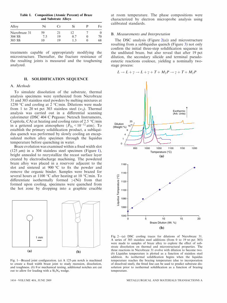
The DSC analysis (Figure 2(a)) and microstructureresulting from a subliquidus quench (Figure 3) not onlyconfirm the initial three-step solidification sequence inthe undiluted braze, but also reveal that after 19 pctdilution, the secondary silicide and terminal pseudo-eutectic reactions coalesce, yielding a nominally two-stage process:
L! Lþ c! Lþ cþ TþM2P! cþ TþM2P
Table I. Composition (Atomic Percent) of Braze
and Substrate Alloys
Alloy Ni Cr Si P Fe
Nicrobraze 31 59 21 12 7 0304 SS 7.5 19 0.7 0 70303 SS 10 19 1.3 0 68
1 mm
(a) (b)
Fig. 1—Brazed joint configuration. (a) A 125-lm notch is machinedto create a fixed width braze joint to study recession, dissolution,and toughness. (b) For mechanical testing, additional notches are cutout to allow for loading with a Si3N4 wedge.
950 1000 1050 1100 1150 1200
Temperature (°C)
16
0
1
25
4
9
19
Exothermic(Arb. Units)
Dilution(Weight %)
(a)
1040
1060
1080
1100
1120
1140
1160
0 5 10 15 20
Braze Dilution (Wt. %)
Liqu
idus
Tem
pera
ture
(°C
)
(b)
Fig. 2—(a) DSC cooling traces for dilutions of Nicrobraze 31.A series of 303 stainless steel additions (from 0 to 19 wt pct 303)were made to samples of braze alloy to explore the effect of sub-strate dissolution on thermal and microstructural properties. Thethree reactions in Nicrobraze 31 evolve with dilution to become two.(b) Liquidus temperature is plotted as a function of stainless steeladdition. As isothermal solidification begins when the liquidustemperature reaches the brazing temperature (due to incorporationof dissolved steel), the fitted line can be used to predict substrate dis-solution prior to isothermal solidification as a function of brazingtemperature.
1414—VOLUME 40A, JUNE 2009 METALLURGICAL AND MATERIALS TRANSACTIONS A

The dilution of the braze causes the liquidus to rise by5 �C/ws (Figure 2(b)) (due to the addition of Fe), whilethe two other reactions converge to a single exotherm(Figure 2(a)). The merging of the silicide into theterminal pseudo-eutectic reaction (Figure 2(a)) corre-lates with the near elimination of the massive silicideparticles and the appearance of silicide in the lathlikeeutectic microstructure (Figure 4). Concurrently, the Feand Ni content of the primary c-(Ni) domains evolvesmonotonically (Figure 5(a)). The addition of stainlesssteel to the braze causes the solidification pathwaybelow the liquidus to shift as follows: the originalsequence comprising precipitation of c-(Ni) and silicidefrom the twofold saturation volume of the silicidereaction, followed by precipitation from the threefoldsaturation surface of the terminal pseudo-eutectic, issuperseded by a saturation space shift wherein precip-itation from the twofold silicide saturation volume issignificantly reduced in favor of precipitation of all threesolid phases from a single four-phase saturation path ofthe terminal pseudo-eutectic. The resulting microstruc-ture simplifies to primary c-(Ni) in a three-phase field ofa eutecticlike microstructure. This intermediate solidifi-cation sequence was unreported in previous work,wherein the silicide secondary reaction was eliminatedentirely after 45 pct dilution, corresponding to a three-phase terminal reaction.[10]
The drop quenching experiments reveal that a contin-uous layer of c-(Ni) forms on the substrate 3 minutesafter the specimen reaches the liquidus temperature,indicating that the dissolution reaction is complete at thattime (Figure 6). Since the dissolution M reprecipitationreaction terminates with the onset of isothermal solidi-fication, dissolution continues until the liquidus of theevolving liquid reaches the brazing temperature. Thus,the evolution of the liquidus temperature leads to adirect relationship between brazing temperature and
early-stage recession (as distinct from the diffusion-controlled pseudo-steady-state recession[10]) (Figure 2(b)).Once the isothermal c-(Ni) seals the substrate from
contact with the liquid, solid-state diffusion through thec-(Ni) controls continued evolution of the joint, leadingto the formation of c-(Ni) cells, which then increasein size, with corresponding changes in composition(Figures 6 and 5(b)). Meanwhile, the large c-(Ni) islandsin the interior, which form on cooling, diminish rapidlyand are eliminated entirely after 4 hours. Accordingly,the Fe and Ni contents (in mole fraction, X) ofthe primary c-(Ni) vary parabolically with time tð Þ :XNi;Fe /
ffiffiffi
t;p
as expected for a diffusion-controlledprocess. Diffusion control is evident for all braze timesshown, confirming that the c-(Ni) layer on the substrate iseffectively continuous after just 3 minutes. By invoking
Fig. 3—Interrupted quench of 9 pct-303ss. Sample was encapsulatedin quartz under Ar and cooled from 1100 �C to 1055 �C (the liqui-dus for this alloy is �1100 �C); then it was water quenched. c-(Ni)can be seen clearly as the primary phase.
Fig. 4—Microstructural comparison of (a) Nicrobraze 31 to (b) Nicro-braze 31 with 19 pct 303ss. In (a), the three phases present are (i) theductile c-(Ni), which appears with bright contrast, present as bothlarge primary grains and within the eutectic; (ii) the ternary phosphide,present as the second component of the eutectic having a darkerappearance; and (iii) the quaternary silicide, which forms large irregu-lar grains (with intermediate contrast) adjacent to both the primaryc-(Ni) and the eutectic. The phases in (b) are equivalent, thoughthe silicide grains are significantly smaller and greater fine eutectic ispresent.
METALLURGICAL AND MATERIALS TRANSACTIONS A VOLUME 40A, JUNE 2009—1415

the proportionality, XNi,Fe � wS, the dilution andbrazing time can be plotted on complementary axes(Figure 5(b)). This construction allows correlation oftotal substrate recession to brazing time (at 1100 �C),whereupon the dissolution M reprecipitation reactionleads to �12 pct dilution of the braze alloy. Thisestimate is consistent with that predicted by the liquidustemperature; for a brazing at 1100 �C, isothermalsolidification commences at �9 pct dilution.
III. HEAT TREATMENTS
Dissolution M reprecipitation occurs so rapidly that itis impractical to circumvent. However, by combiningshort brazing times with drop quenching, c-(Ni) den-drites form and extend from the surface of the isother-mal cells, preferentially oriented perpendicular to the
joint (Figure 6). A heat treatment was developed tocoarsen the elongated structure of the c-(Ni) particles.The coarsening is conducted at 1015 �C, where there issufficient liquid to facilitate rapid coarsening whileavoiding remelting of the c-(Ni) dendrites. This temper-ature was chosen because the c-(Ni) dendrites are, inpart, a product of coprecipitation with the silicide. Thisresults in coarsening of the silicide as well as the c-(Ni),but coarsening above the silicide crystallization temper-ature is ineffective due to the low volume fraction ofc-(Ni).The thermal profiles for quenching, Qo, and coarsen-
ing, QC, as well as the ensuing microstructures, aredepicted in Figure 7, relative to a standard braze cycle.Both exhibit centerline precipitation of c-(Ni). Themicrostructure of the QC specimens comprises elongatedc-(Ni) domains that traverse the bond, albeit nonperco-lating, surrounded by silicide islands and a eutecticmicrostructure. The coarsening takes place rapidly andis complete after only a few minutes; longer coarseningtreatments result in nearly identical microstructures (notshown). Local microhardness measurements conductedwithin the c-(Ni) domains by using a Vickers indenter ata 200-g load revealed a hardness, H = 2.4 GPa,indicative of a yield strength, ro � 800 MPa.[15] Thisstrength is lower than that inferred from measurementson the eutectic c-(Ni) obtained by nanoindentation atmuch smaller penetrations, ro � 1.3 GPa.[7] This inden-tation size effect is attributed to the plasticity lengthscale.[16] In the ensuing analysis of ductile-phase tough-ening, the smaller value will be used for the largedomains and vice versa.
IV. FRACTURE RESISTANCE
A. Experimental Methods
After brazing, double cantilever beam test configura-tions were machined by wire electrodischarge machin-ing, followed by testing in displacement control in aservohydraulic frame instrumented with a load cell anda crack opening gage. Precracks were introduced using aSi3N4 wedge, while constraining with a transverseclamp, and then delineated by heat tinting at 600 �Cfor 15 minutes.[7] The fracture resistance was measuredby wedge loading with the clamp removed.[7] Crackprofiles were investigated by optical and electron micro-scopy. The fracture surfaces were characterized byscanning electron microscopy (SEM), and transversefeatures were revealed by creating local cross sectionswith a focused ion beam (FIB). The testing andcharacterization were performed on specimens subjectto brazing at 1100 �C for 3 minutes and drop quenching(the Qo treatment), as well as others subjected toadditional coarsening at 1015 �C for 10 minutes (desig-nated QC).
B. Measurements and Observations
The fracture resistances measured for the two heattreatments are summarized in Table II. Evidently, both
Ni
Cr
Si
Fe
P0
25
50
0 10 20
Dilution (Weight % 303)
Con
cent
ratio
n (A
tom
ic %
)
(a)
Ni
FeCr
Si
P0
25
50
Con
cent
ratio
n (A
tom
ic %
)
0 0.05 1Brazing Time (h)
2515 20
Dilution of Braze (Wt. %)
Isothermal Solidification
DissolutionReprecipitation
(b)
4
Fig. 5—Elemental composition (in atomic percent) of primary c-(Ni)as a function of (a) dilution by 303 stainless steel and (b) brazingtime (measured from when the specimen reaches the braze liquidus)for a joint in 304 stainless steel. Dilution for the brazed joint hasbeen calculated and plotted on the secondary axis of abscissae.
1416—VOLUME 40A, JUNE 2009 METALLURGICAL AND MATERIALS TRANSACTIONS A

Fig. 6—Evolution of microstructure for joints brazed and drop quenched. Primary c-(Ni) is evident as the large particles with bright contrast,both adjacent to the steel substrate and in the joint interior. The dark field along the center of the joint comprises a fine-grained combination ofadditional c-(Ni) and both intermetallics.
10 min
120 min3 min
15 135
1100°C
1000°C
950°C
1050°CLiquidus
Time (min)
100 µm
100 µm
100 µm
Coarsened (QC)
Quenched (Qo) Standard (S)
Fig. 7—Results of drop quench (Qo) and coarsening (QC) braze schedules. Joint microstructures for the novel heat treatments are shown andcompared with the previous work (S) (a joint brazed at 1100 �C for 2 h and cooled at 10 �C/min[7]). The heat treatment profile is plotted foreach sample type. Note the preferential perpendicular orientation of the c-(Ni) to the joint line in Qo and QC.
METALLURGICAL AND MATERIALS TRANSACTIONS A VOLUME 40A, JUNE 2009—1417
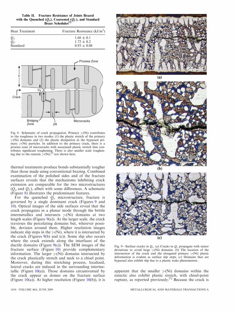
thermal treatments produce bonds substantially tougherthan those made using conventional brazing. Combinedexamination of the polished sides and of the fracturesurfaces reveals that the mechanisms inhibiting crackextension are comparable for the two microstructures(Qo and QC), albeit with some differences. A schematic(Figure 8) illustrates the predominant features.
For the quenched Qo microstructure, fracture isgoverned by a single dominant crack (Figures 9 and10). Optical images of the side surfaces reveal that thecrack propagates in a planar mode through the brittleintermetallics and intersects c-(Ni) domains at twolength scales (Figure 9(a)). At the larger scale, the cracktraverses the percolating domains but, wherever possi-ble, deviates around them. Higher resolution imagesindicate slip steps in the c-(Ni), where it is intersected bythe crack (Figures 9(b) and (c)). Some slip also occurswhere the crack extends along the interfaces of theductile domains (Figure 9(c)). The SEM images of thefracture surface (Figure 10) provide complementaryinformation. The larger c-(Ni) domains intersected bythe crack plastically stretch and neck to a chisel point.Moreover, during this stretching process, localized,lateral cracks are induced in the surrounding interme-tallic (Figure 10(a)). Those domains circumvented bythe crack appear as domes on the fracture surface(Figure 10(a)). At higher resolution (Figure 10(b)), it is
apparent that the smaller c-(Ni) domains within theeutectic also exhibit plastic stretch, with chisel-pointrupture, as reported previously.[7] Because the crack is
Table II. Fracture Resistance of Joints Brazed
with the Quenched (Qo), Coarsened (QC), and Standard
Braze Schedules[7]
Heat Treatment Fracture Resistance (kJ/m2)
Qo 1.68 ± 0.1QC 1.72 ± 0.2Standard 0.93 ± 0.08
BridgingZone
Microcracks
cu
Crack
Process Zone
h
2R
Fig. 8—Schematic of crack propagation. Primary c-(Ni) contributesto the toughness in two modes: (1) the plastic stretch of the primaryc-(Ni) domains and (2) the plastic dissipation in the bypassed pri-mary c-(Ni) particles. In addition to the primary crack, there is aprocess zone of microcracks with associated plastic stretch that con-tributes significant toughening. There is also smaller scale toughen-ing due to the eutectic c-(Ni),[7] not shown here.
Fig. 9—Surface cracks in Qo. (a) Cracks in Qo propagate with minordeviations to avoid large c-(Ni) domains. (b) The location of theintersection of the crack and the elongated primary c-(Ni) plasticdeformation is evident as surface slip steps. (c) Domains that arebypassed also exhibit slip due to a plastic wake phenomenon.
1418—VOLUME 40A, JUNE 2009 METALLURGICAL AND MATERIALS TRANSACTIONS A
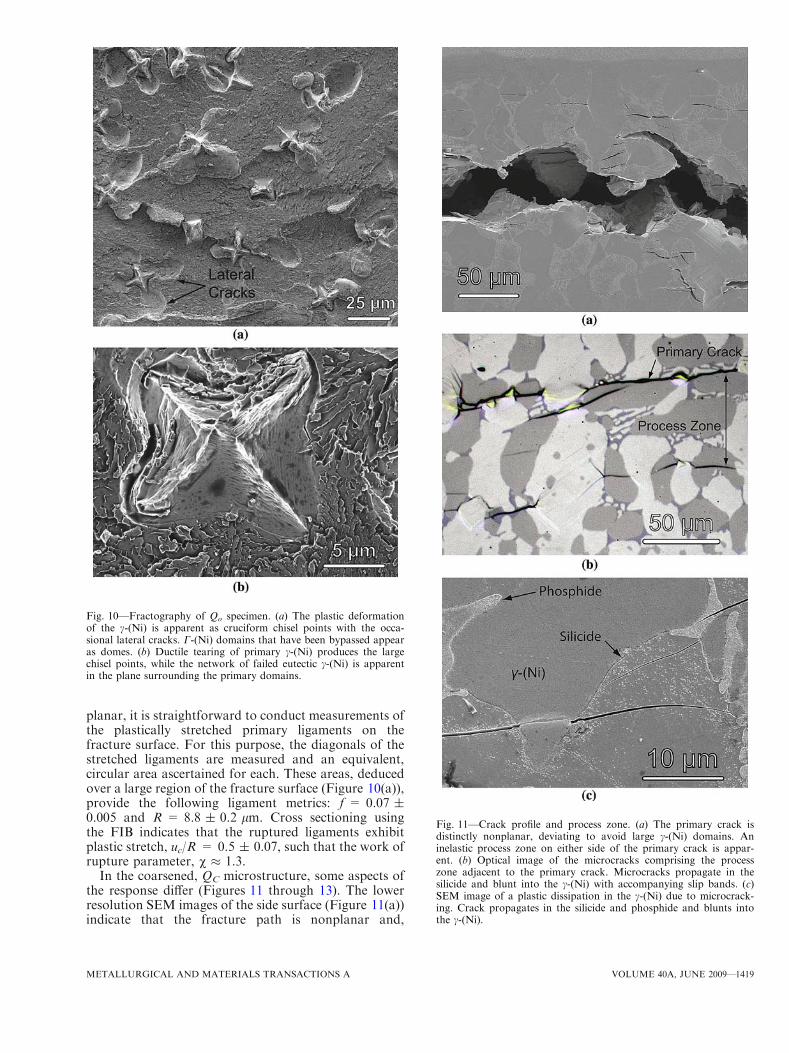
planar, it is straightforward to conduct measurements ofthe plastically stretched primary ligaments on thefracture surface. For this purpose, the diagonals of thestretched ligaments are measured and an equivalent,circular area ascertained for each. These areas, deducedover a large region of the fracture surface (Figure 10(a)),provide the following ligament metrics: f = 0.07 ±0.005 and R = 8.8 ± 0.2 lm. Cross sectioning usingthe FIB indicates that the ruptured ligaments exhibitplastic stretch, uc/R = 0.5 ± 0.07, such that the work ofrupture parameter, v � 1.3.
In the coarsened, QC microstructure, some aspects ofthe response differ (Figures 11 through 13). The lowerresolution SEM images of the side surface (Figure 11(a))indicate that the fracture path is nonplanar and,
Fig. 10—Fractography of Qo specimen. (a) The plastic deformationof the c-(Ni) is apparent as cruciform chisel points with the occa-sional lateral cracks. C-(Ni) domains that have been bypassed appearas domes. (b) Ductile tearing of primary c-(Ni) produces the largechisel points, while the network of failed eutectic c-(Ni) is apparentin the plane surrounding the primary domains.
Fig. 11—Crack profile and process zone. (a) The primary crack isdistinctly nonplanar, deviating to avoid large c-(Ni) domains. Aninelastic process zone on either side of the primary crack is appar-ent. (b) Optical image of the microcracks comprising the processzone adjacent to the primary crack. Microcracks propagate in thesilicide and blunt into the c-(Ni) with accompanying slip bands. (c)SEM image of a plastic dissipation in the c-(Ni) due to microcrack-ing. Crack propagates in the silicide and phosphide and blunts intothe c-(Ni).
METALLURGICAL AND MATERIALS TRANSACTIONS A VOLUME 40A, JUNE 2009—1419

moreover, that an inelastic process zone develops onboth sides of the crack, having width h � 50 lm. Opticaland higher resolution SEM images (Figures 11(b) and(c)) indicate that this zone comprises discrete micro-cracks in the intermetallic, with associated bluntingwhere arrested by the c-(Ni), accompanied by slip bands.The residual opening displacement of the microcracks isof order dmicro � 0.5 lm.
At locations where the crack intersects the largerc-(Ni) domains, plastic stretch is accompanied byintense slip bands in the contiguous c-(Ni), causingthem to fail by shear, rather than necking (Figure 12).The SEM images of the fracture surface (Figure 13)affirm that the rupture of the c-(Ni) domains occurs by ashear mechanism. It remains to provide a rationale forthe change in the rupture mechanism in the ligamentsupon aging, from tensile necking to shear banding. Thearea fraction and width of domains intersected by thecrack are estimated from the images as f � 0.03 and2R � 30 lm. The plastic stretch on the verge of ruptureis ascertained from the images on the side surface(Figure 12(b)) as uc/R � 0.5, with a work of ruptureagain, v � 1.3.
C. Interpretation
The forgoing assessment suggests two contributionsto the toughening: one from bridging and the other froma process zone (Figure 8).[14] The bridging contributionis straightforward to interpret through the foregoingmeasurements of the plastic stretch. For the quenched,Qo, microstructure, upon combining the inferred yieldstrength for the primary c-(Ni) domains, ro � 800 MPa,with the ligament volume fraction and size yields apredicted toughening, DCprimary
ss ¼ 0:66� 0:1 kJ/m�2:This toughening is additive to that provided by thec-(Ni) in the eutectic, previously determined as[7]
DCeutecticss ¼ 0:45 kJ/m2: The total bridging contribution
is thus DCss ¼ 1:1� 0:2 kJ/m2; appreciably lower thanthe measured toughness. The remainder is presumed tobe due to the plastic dissipation in those c-(Ni) domainscircumvented by the crack, but not quantified.
Fig. 12—Profile of stretched primary c-(Ni) ligaments in coarsened,QC, specimens. (a) The crack intersects a primary c-(Ni) domainresulting in intense slip bands. (b) Plastic stretch ratios weremeasured at the onset of ductile rupture, uc/R � 0.5.
Fig. 13—Fracture surface of coarsened, QC, specimens. (a) The frac-ture surface is rough and nonplanar. Stretched ligaments appear aschisel points with a depressed border. Bypassed ligaments result indomes. (b) The stretched ligaments retain the cruciform chisel pointmorphology of Qo, but it is less distinct.
1420—VOLUME 40A, JUNE 2009 METALLURGICAL AND MATERIALS TRANSACTIONS A
For the coarsened, QC, microstructure, the corre-sponding bridging contribution is somewhat smaller,DCprimary
ss ¼ 0:46 kJ/m�2: Upon adding the tougheningdue to the c-(Ni) in the eutectic, the total bridgingcontribution becomes DCss ¼ 0:9 kJ/m2: In this case, aprocess zone contribution can be estimated using[14]
DCprocess ¼ 2ro
Z h
0
epl yð Þdy
where epl is the inelastic strain at location y within thezone and h is the zone height. The opening displacementsof the microcracks in the process zone suggest averageplastic strains, �epl � dmicro=h; whereupon the predictedtoughening reduces to DCprocess � 2rodmicro. Based onthe foregoing measurements of dmicro, this contributionto toughening becomes DCprocess � 0.8 kJ/m2. Thus, thetotal toughening due to both ductile-phase mechanismsat both length scales, DCss � 1.7 kJ/m2, accounts fullyfor the measured toughness.
While establishing a fully predictable contribution totoughening from the coarse ductile phases remains to bedone, the foregoing assessment suggests that the bridg-ing contribution is substantial. The implication is that, ifpercolation of the c-(Ni) domains could be achieved byan appropriate thermal process, this contribution to thetoughening could be increased further and greaterrobustness imparted to the joint.
V. CONCLUDING REMARKS
Counter to conventional wisdom, the deleteriousinfluence of the intermetallic phases at the braze jointcenterline has been mitigated by using very short brazingtimes. The resulting microstructure contains large c-(Ni)domains that provide ductile-phase toughening. Thedevelopment of this beneficial microstructure has beenbased on analysis of transient liquid-phase phenomena,as well as the pseudo-steady-state diffusive processes.The present heat treatment is illustrative of an approachthat exploits an understanding of microstructure evolu-tion for enhancing the robustness of brazed joints.Further toughening might be achieved by eliminating
the massive silicide and, most importantly, by achievingpercolation of primary c-(Ni) across the joint. Thismight be realized by increasing the brazing temperaturein order to eliminate the largest intermetallic particles,followed by heat treatments that enable c-(Ni) percola-tion.
OPEN ACCESS
This article is distributed under the terms ofthe Creative Commons Attribution NoncommercialLicense which permits any noncommercial use, distri-bution, and reproduction in any medium, provided theoriginal author(s) and source are credited.
REFERENCES1. Z. Wei, K.P. Dharmasena, H.N.G. Wadley, and A.G. Evans: Int.
J. Impact. Eng., 2007, vol. 34 (10), pp. 1602–18.2. J.W. Hutchinson and Z.Y. Xue: Int. J. Mech. Sci., 2005, vol. 47
(4–5), pp. 545–69.3. S.L.D.E. Lucato, J. Wang, P. Maxwell, R.M. McMeeking, and
A.G. Evans: Int. J. Solids Struct., 2004, vol. 41 (13), pp. 3521–43.4. F.W. Zok, H.J. Rathbun, Z. Wei, and A.G. Evans: Int. J. Solids
Struct., 2003, vol. 40 (21), pp. 5707–22.5. L. Valdevit, N. Vermaak, F.W. Zok, and A.G. Evans: J. Appl.
Mech., 2008, vol. 75 (6), p. 061022.6. H.N.G. Wadley, N.A. Fleck, and A.G. Evans: Compos. Sci.
Technol., 2003, vol. 63 (16), pp. 2331–43.7. N.R. Philips, M.Y. He, and A.G. Evans: Acta Mater., 2008,
vol. 56 (17), pp. 4593–4600.8. W.F. Gale and D.A. Butts: Sci. Technol. Weld. Join., 2004, vol. 9
(4), pp. 283–300.9. X.W. Wu, R.S. Chandel, H.P. Seow, and H. Li: J. Mater. Process.
Technol., 2001, vol. 113, pp. 215–21.10. N.R. Philips, C.G. Levi, and A.G. Evans:Metall. Mater. Trans. A,
2008, vol. 39A, pp. 142–49.11. M.F. Ashby, F.J. Blunt, and M. Bannister: Acta Metall., 1989,
vol. 37 (7), pp. 1847–1857.12. M.G. Mendiratta, J. Lewandowski, and D.M. Dimiduk: Metall.
Trans. A, 1991, vol. 22A, pp. 1573–83.13. B.D. Flinn, C.S. Lo, F.W. Zok, and A.G. Evans: J. Am. Ceram.
Soc., 1993, vol. 76 (2), pp. 369–75.14. A.G. Evans: J. Am. Ceram. Soc., 1990, vol. 73 (2), pp. 187–206.15. D. Tabor: Br. J. Appl. Phys., 1956, vol. 7 (5), pp. 159–66.16. M.R. Begley and J.W. Hutchinson: J. Mech. Phys. Solids, 1998,
vol. 46 (10), pp. 2049–68.
METALLURGICAL AND MATERIALS TRANSACTIONS A VOLUME 40A, JUNE 2009—1421


![PDF] Carbide Materials Brazed Tools KCemented Carbide Material Features and Applications. K3 Carbide Materials Brazed Tools K ... Carbide Materials Brazed Tools K Drill Blanks with](https://static.fdocuments.in/doc/165x107/612d50e61ecc515869421cfd/-carbide-materials-brazed-tools-kcemented-carbide-material-features-and-applications.jpg)