
Brazed heat exchangers - Midstates Refrigeration
16
A product catalogue for refrigeration Brazed heat exchangers
Transcript of Brazed heat exchangers - Midstates Refrigeration
A product catalogue for refrigeration
Brazed heat exchangers
2
The brazed plate heat exchanger (BHE) is a well-establishedcomponent in a refrigeration plant. In refrigeration plants whereAlfa Laval BHEs are installed, typical equipment includes:
• Chiller: Cools water or brine and rejects the heat to air orwater. The water is transported by a hydraulic systemthrough different types of heat exchanger to cool air in anair conditioning system or to cool manufacturing or indu-strial processes. Two basic systems are normally used todrive chillers: a compressor driven by an electric motor,based on a vapour compression refrigeration cycle; or aheat-driven system (steam, burning natural gas), based onan absorption refrigeration cycle.
• Heat pump: A type of water chiller that can also run in areverse cycle, also called a water-source heat pump. In thiscase the primary function is heating water and rejecting thecool to air or water. The heated water warms up air in theair conditioning system. Another variation of this system is
ground source heat pumps, using the earth or water surfaceto add or reject the heat.
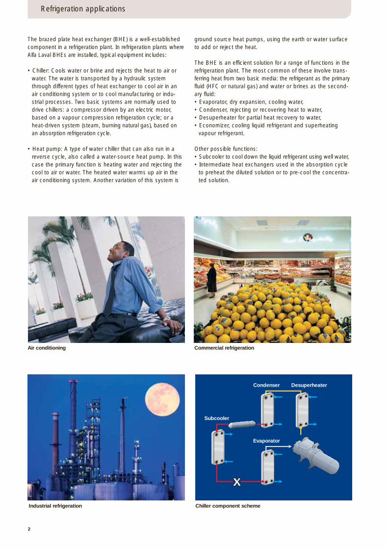
The BHE is an efficient solution for a range of functions in therefrigeration plant. The most common of these involve trans-ferring heat from two basic media: the refrigerant as the primaryfluid (HFC or natural gas) and water or brines as the second-ary fluid:• Evaporator, dry expansion, cooling water,• Condenser, rejecting or recovering heat to water,• Desuperheater for partial heat recovery to water,• Economizer, cooling liquid refrigerant and superheating
vapour refrigerant.
Other possible functions: • Subcooler to cool down the liquid refrigerant using well water,• Intermediate heat exchangers used in the absorption cycle
to preheat the diluted solution or to pre-cool the concentra-ted solution.
Refrigeration applications
Air conditioning Commercial refrigeration
Industrial refrigeration Chiller component scheme
Condenser
Subcooler
Evaporator
Desuperheater
3
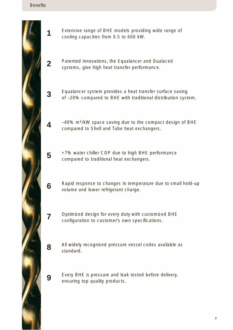
Benefits
Extensive range of BHE models providing wide range of cooling capacities from 0.5 to 600 kW.
Equalancer system provides a heat transfer surface saving of –20% compared to BHE with traditional distribution system.
–40% m3/kW space saving due to the compact design of BHEcompared to Shell and Tube heat exchangers.
+7% water chiller COP due to high BHE performancecompared to traditional heat exchangers.
Rapid response to changes in temperature due to small hold-upvolume and lower refrigerant charge.
Patented innovations, the Equalancer and Dualacedsystems, give high heat transfer performance.
Every BHE is pressure and leak tested before delivery,ensuring top quality products.
Optimized design for every duty with customized BHE configuration to customer’s own specifications.
All widely recognized pressure vessel codes available as standard.
1
2
3
4
5
6
7
8
9
4
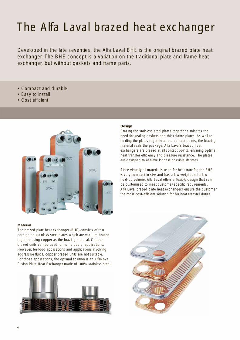
The Alfa Laval brazed heat exchanger
• Compact and durable• Easy to install• Cost efficient
Developed in the late seventies, the Alfa Laval BHE is the original brazed plate heatexchanger. The BHE concept is a variation on the traditional plate and frame heatexchanger, but without gaskets and frame parts.
MaterialThe brazed plate heat exchanger (BHE) consists of thin corrugated stainless steel plates which are vacuum brazedtogether using copper as the brazing material. Copper brazed units can be used for numerous of applications.However, for food applications and applications involvingaggressive fluids, copper brazed units are not suitable. For those applications, the optimal solution is an AlfaNovaFusion Plate Heat Exchanger made of 100% stainless steel.
DesignBrazing the stainless steel plates together eliminates theneed for sealing gaskets and thick frame plates. As well asholding the plates together at the contact points, the brazingmaterial seals the package. Alfa Laval’s brazed heatexchangers are brazed at all contact points, ensuring optimalheat transfer efficiency and pressure resistance. The platesare designed to achieve longest possible lifetimes.
Since virtually all material is used for heat transfer, the BHE is very compact in size and has a low weight and a low hold-up volume. Alfa Laval offers a flexible design that can be customized to meet customer-specific requirements. Alfa Laval brazed plate heat exchangers ensure the customerthe most cost-efficient solution for his heat transfer duties.
5
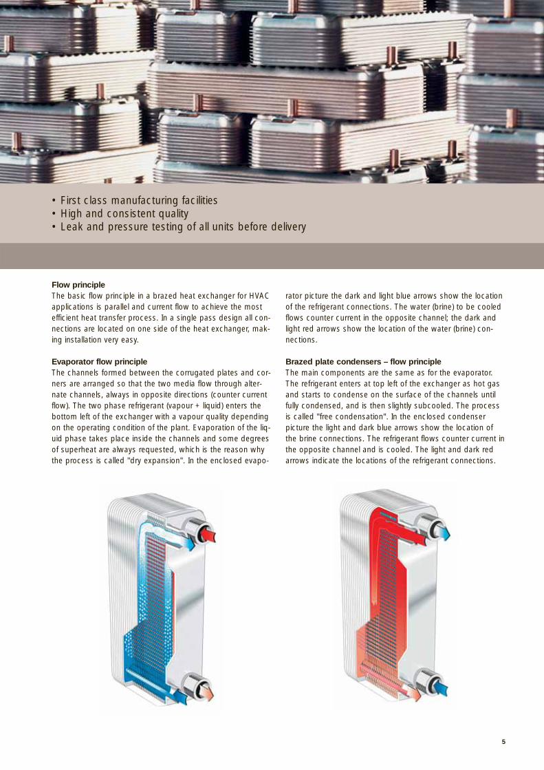
Flow principleThe basic flow principle in a brazed heat exchanger for HVACapplications is parallel and current flow to achieve the mostefficient heat transfer process. In a single pass design all con-nections are located on one side of the heat exchanger, mak-ing installation very easy.
Evaporator flow principleThe channels formed between the corrugated plates and cor-ners are arranged so that the two media flow through alter-nate channels, always in opposite directions (counter currentflow). The two phase refrigerant (vapour + liquid) enters thebottom left of the exchanger with a vapour quality dependingon the operating condition of the plant. Evaporation of the liq-uid phase takes place inside the channels and some degreesof superheat are always requested, which is the reason whythe process is called "dry expansion". In the enclosed evapo-
rator picture the dark and light blue arrows show the locationof the refrigerant connections. The water (brine) to be cooledflows counter current in the opposite channel; the dark andlight red arrows show the location of the water (brine) con-nections.
Brazed plate condensers – flow principleThe main components are the same as for the evaporator.The refrigerant enters at top left of the exchanger as hot gasand starts to condense on the surface of the channels untilfully condensed, and is then slightly subcooled. The processis called "free condensation". In the enclosed condenser picture the light and dark blue arrows show the location ofthe brine connections. The refrigerant flows counter current inthe opposite channel and is cooled. The light and dark redarrows indicate the locations of the refrigerant connections.
• First class manufacturing facilities• High and consistent quality• Leak and pressure testing of all units before delivery
6
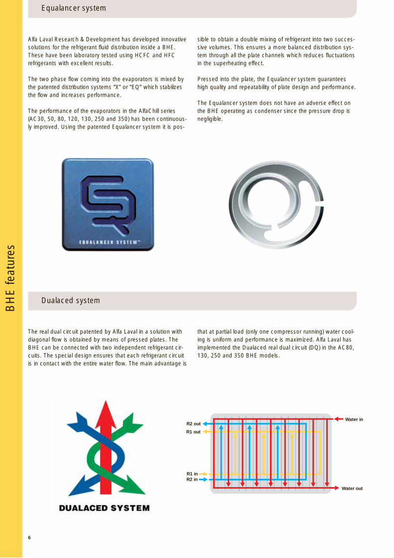
The real dual circuit patented by Alfa Laval in a solution withdiagonal flow is obtained by means of pressed plates. TheBHE can be connected with two independent refrigerant cir-cuits. The special design ensures that each refrigerant circuitis in contact with the entire water flow. The main advantage is
that at partial load (only one compressor running) water cool-ing is uniform and performance is maximized. Alfa Laval hasimplemented the Dualaced real dual circuit (DQ) in the AC80,130, 250 and 350 BHE models.
Dualaced system
Alfa Laval Research & Development has developed innovativesolutions for the refrigerant fluid distribution inside a BHE.These have been laboratory tested using HCFC and HFCrefrigerants with excellent results.
The two phase flow coming into the evaporators is mixed bythe patented distribution systems “X” or “EQ” which stabilizesthe flow and increases performance.
The performance of the evaporators in the AlfaChill series(AC30, 50, 80, 120, 130, 250 and 350) has been continuous-ly improved. Using the patented Equalancer system it is pos-
sible to obtain a double mixing of refrigerant into two succes-sive volumes. This ensures a more balanced distribution sys-tem through all the plate channels which reduces fluctuationsin the superheating effect.
Pressed into the plate, the Equalancer system guaranteeshigh quality and repeatability of plate design and performance.
The Equalancer system does not have an adverse effect onthe BHE operating as condenser since the pressure drop isnegligible.
Equalancer systemB
HE
feat
ures
Water in
Water out
R2 out
R1 out
R1 inR2 in
7
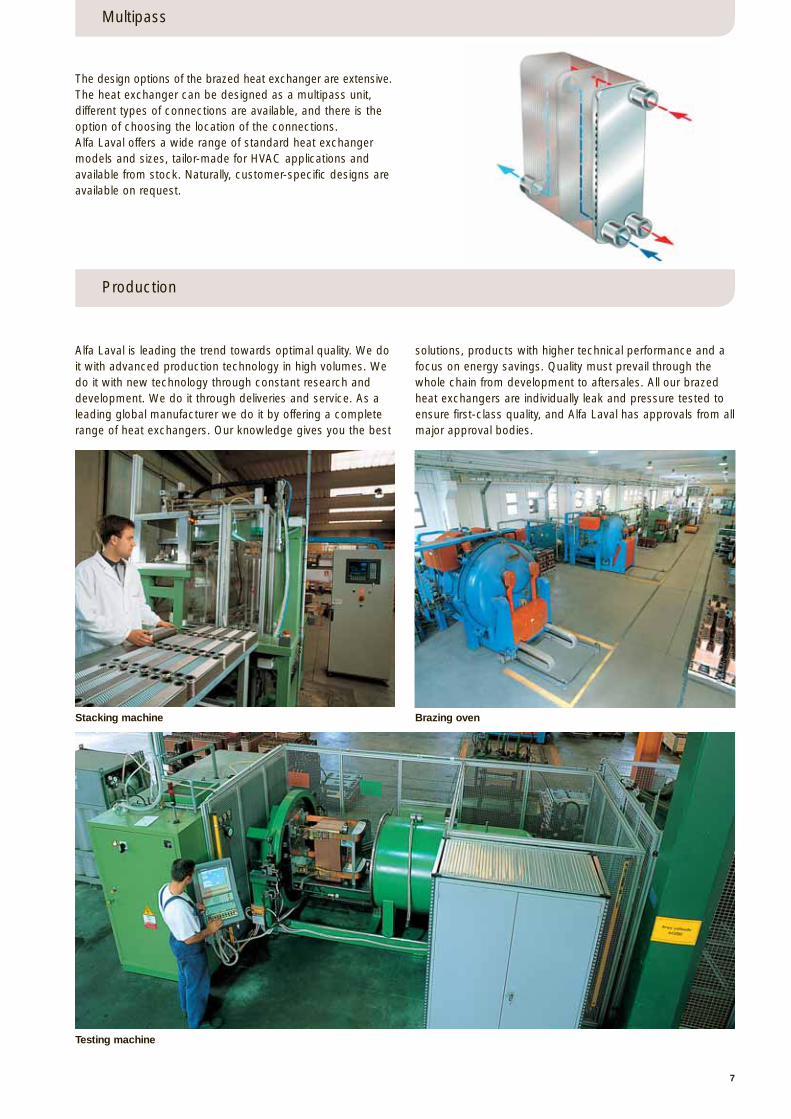
Alfa Laval is leading the trend towards optimal quality. We doit with advanced production technology in high volumes. Wedo it with new technology through constant research anddevelopment. We do it through deliveries and service. As aleading global manufacturer we do it by offering a completerange of heat exchangers. Our knowledge gives you the best
solutions, products with higher technical performance and afocus on energy savings. Quality must prevail through thewhole chain from development to aftersales. All our brazedheat exchangers are individually leak and pressure tested toensure first-class quality, and Alfa Laval has approvals from allmajor approval bodies.
Multipass
The design options of the brazed heat exchanger are extensive.The heat exchanger can be designed as a multipass unit, different types of connections are available, and there is theoption of choosing the location of the connections. Alfa Laval offers a wide range of standard heat exchangermodels and sizes, tailor-made for HVAC applications andavailable from stock. Naturally, customer-specific designs areavailable on request.
Production
Stacking machine Brazing oven
Testing machine
CB26/27
Ext. threaded (ISO 228/1-G)
Ext. threaded (ISO 228/1-G)
Ext. threaded (ISO 228/1-G)
Ext. threaded (ISO 228/1-G)
S3S4
S1-S2 , T1-T2
CB76
Internal soldering
AC50
AC10
A21 3/4”
Internal solderingRef IN
Ref OUTWater side
S3S3S4S4
S1-S2T1-T2
H21R21H21R21
ODS 1”1/81”1/4 – 12UNF
ODS 1”1/81”1/4 – 12UNF
Internal solderingRotalock
Internal solderingRotalock
POSITION
8
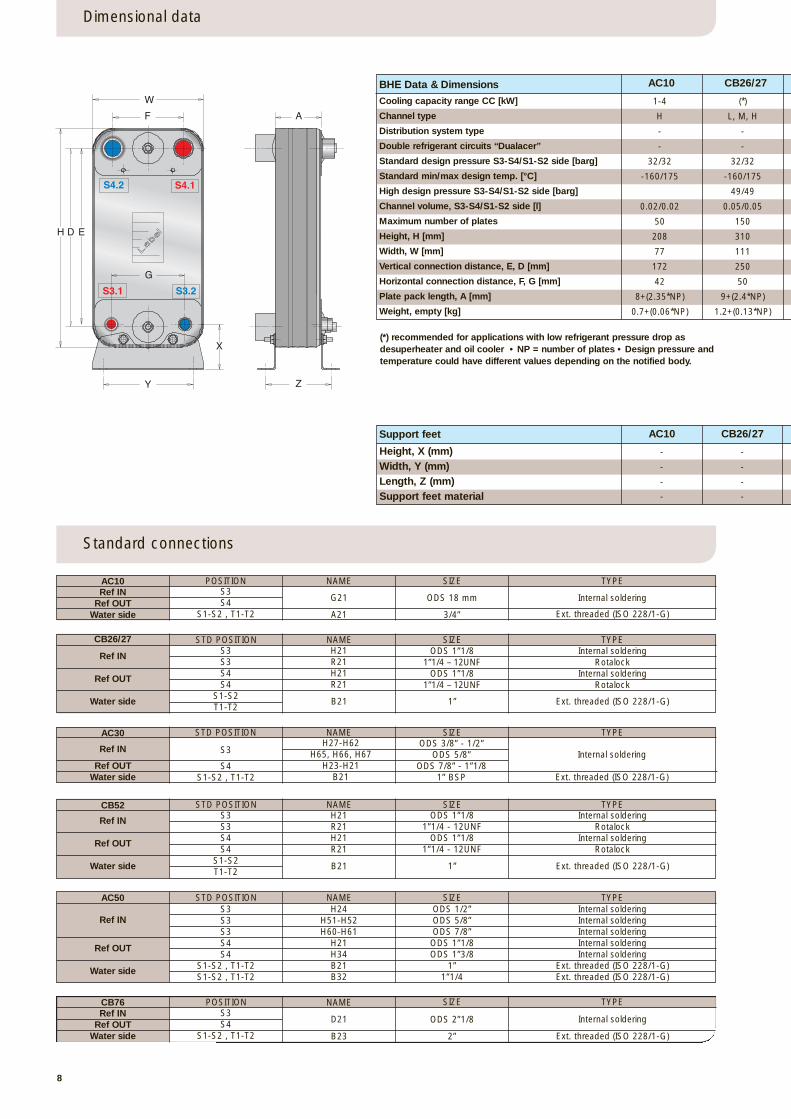
Dimensional data
Standard connections
NAME SIZE TYPE
STD POSITION NAME
B21 1”
SIZE TYPE
Ref IN
Ref OUT
Water side
H21R21H21R21
ODS 1”1/81”1/4 - 12UNF
ODS 1”1/81”1/4 - 12UNF
Internal solderingRotalock
Internal solderingRotalock
STD POSITIONCB52 NAME
B21 1”
SIZE TYPE
Ref IN
Ref OUT
Water side
H24H51-H52H60-H61
H21H34B21B32
ODS 1/2”ODS 5/8”ODS 7/8”
ODS 1”1/8ODS 1”3/8
1”1”1/4
Internal solderingInternal solderingInternal solderingInternal solderingInternal soldering
Ext. threaded (ISO 228/1-G)Ext. threaded (ISO 228/1-G)
STD POSITION NAME SIZE TYPE
Ref IN
Ref OUT
Water side
D21
B23
ODS 2”1/8
2”
S3S4
S1-S2 , T1-T2
POSITION NAME SIZE TYPE
S3S3S4S4
S1-S2T1-T2
Ref INRef OUT
Water side
S3S3S3S4S4
S1-S2 , T1-T2S1-S2 , T1-T2
Support feet AC10 CB26/27
- -
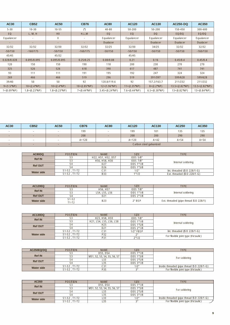
BHE Data & Dimensions
Cooling capacity range CC [kW]
Channel type
Distribution system type
Double refrigerant circuits “Dualacer”
Standard design pressure S3-S4/S1-S2 side [barg]
Standard min/max design temp. [°C]
High design pressure S3-S4/S1-S2 side [barg]
Channel volume, S3-S4/S1-S2 side [l]
Maximum number of plates
Height, H [mm]
Width, W [mm]
Vertical connection distance, E, D [mm]
Horizontal connection distance, F, G [mm]
Plate pack length, A [mm]
Weight, empty [kg]
AC10 CB26/27
(*) recommended for applications with low refrigerant pressure drop as desuperheater and oil cooler • NP = number of plates • Design pressure and temperature could have different values depending on the notified body.
H D E
W
F
Y
X
G
S4.2 S4.1
S3.1 S3.2
Z
A
Height, X (mm)Width, Y (mm)Length, Z (mm)Support feet material
- -
- -
- -
S4S1-S2 , T1-T2
AC30
Ref OUTWater side
STD POSITION NAME SIZE TYPEH27-H62
H65, H66, H67H23-H21
B21
ODS 3/8” - 1/2”ODS 5/8”
ODS 7/8” - 1”1/81” BSP
Internal soldering
Ext. threaded (ISO 228/1-G)
G21 ODS 18 mm
Ref IN S3
1-4 (*)
H L, M, H
- -
- -
32/32 32/32
-160/175 -160/175
49/49
0.02/0.02 0.05/0.05
50 150
208 310
77 111
172 250
42 50
8+(2.35*NP) 9+(2.4*NP)
0.7+(0.06*NP) 1.2+(0.13*NP)
For flexible joint type (Victaulic)
For soldering
Int. threaded (ISO 228/1-G)
Inside threaded (pipe thread ISO 228/1-G)
S3S3S4S4
S1-S2 , T1-T2S1-S2 , T1-T2
AC250EQ/DQ
For flexible joint type (Victaulic)
AC130DQ
AC80DQ
S3S3S4S4
S1-S2 , T1-T2S1-S2 , T1-T2S1-S2 , T1-T2
AC120EQ
9
B23 2” BSP
S3S3S4S4
S1-S2 , T1-T2S1-S2 , T1-T2
H22, H51, H52, D57H56, H58, H30
D27D26C31B33
ODS 5/8”ODS 7/8”
ODS 1”1/8ODS 1”3/8
1/2”1”1/2
Internal soldering
POSITION NAME
Int. threaded (ISO 228/1-G)Ext. threaded (ISO 228/1-G)
SIZE TYPE
Ref IN
Ref OUT
Water side
S3S3S4
S1-S2T1-T2
H56, H57L54, L55, L56
D21
ODS 7/8”ODS 1”1/8ODS 2”1/8
Internal soldering
POSITION NAME
Ext. threaded (pipe thread ISO 228/1)
SIZE TYPE
Ref IN
Ref OUT
Water side
D55, D54M51, 52, 53, 54, 55, 56, 57
L33L35C31P35
ODS 1”1/8ODS 1”3/8ODS 2”5/8ODS 3”1/8
1/2”3”
POSITION NAME
For flexible joint type (Victaulic)
SIZE TYPE
Ref IN
Ref OUT
Water side
AC350S3S3S4S4
S1-S2 , T1-T2S1-S2 , T1-T2
D55, D54M51, 52, 53, 54, 55, 56, 57
L33L35L33L35
ODS 1”1/8ODS 1”3/8ODS 2”5/8ODS 3”1/8
1/2”3”
For soldering
POSITION NAME
Inside threaded (pipe thread ISO 228/1-G)
SIZE TYPE
Ref IN
Ref OUT
Water side
H23, H58, H59H21, L54, L55, L56, L58
H25D21C31P32P31
ODS 7/8”ODS 1”1/8ODS 1”5/8ODS 2”1/81/2” FBSP
2”2”1/2
Internal soldering
NAME SIZE TYPE
Ref IN
Ref OUT
Water side
POSITION
Carbon steel galvanized
AC30 CB52 AC50 CB76 AC80 AC120 AC130 AC250 AC350
- - -
AC30 CB52 AC50 CB76 AC80 AC120 AC130 AC250-DQ AC350
- - - 199 - 199 101 135 135
- - - 208 - 208 200 290 290
- - - A+120 - A+120 A+42 A+54 A+54
5-30 10-30 10-55 (*) 40-80 50-200 50-200 150-450 300-600
EQ L, M, H HX H,L,M EQ EQ DQ EQ/DQ EQ/DQ
Equalancer - X - Equalancer Equalancer Equalancer Equalancer Equalancer
- - - - Dualacer - Dualacer Dualacer Dualacer
32/32 32/32 32/30 32/32 32/25 32/30 34/25 32/32 32/32
-50/150 -160/175 -50/150 -160/175 -50/150 -50/150 -50/150 -50/150 -160/150
45/45 45/32 45/45
0.028/0.028 0.095/0.095 0.095/0.095 0.25/0.25 0.08/0.08 0.21 0.16 0.45/0.4 0.45/0.4
120 150 150 190 118 200 230 270 270
325 526 526 618 390 617 487 741 741
93 111 111 191 195 192 247 324 324
269 466 466 519 296 519 391/397 599/628 599/628
39/40 50 50 92 120.8/119.6 92 157.2/163.7 211/232 211/232
9+(1.5*NP) 10+(2.4*NP) 10+(2.4*NP) 10+(2.85*NP) 12+(1.96*NP) 11+(2.35*NP) 8+(2.2*NP) 13.5+(2.82*NP) 13.5+(2.82*NP)
1+(0.09*NP) 1.8+(0.23*NP) 1.8+(0.23*NP) 7+(0.44*NP) 3.45+(0.24*NP) 7.6+(0.44*NP) 6.5+(0.38*NP) 13+(0.82*NP) 13+(0.84*NP)
10
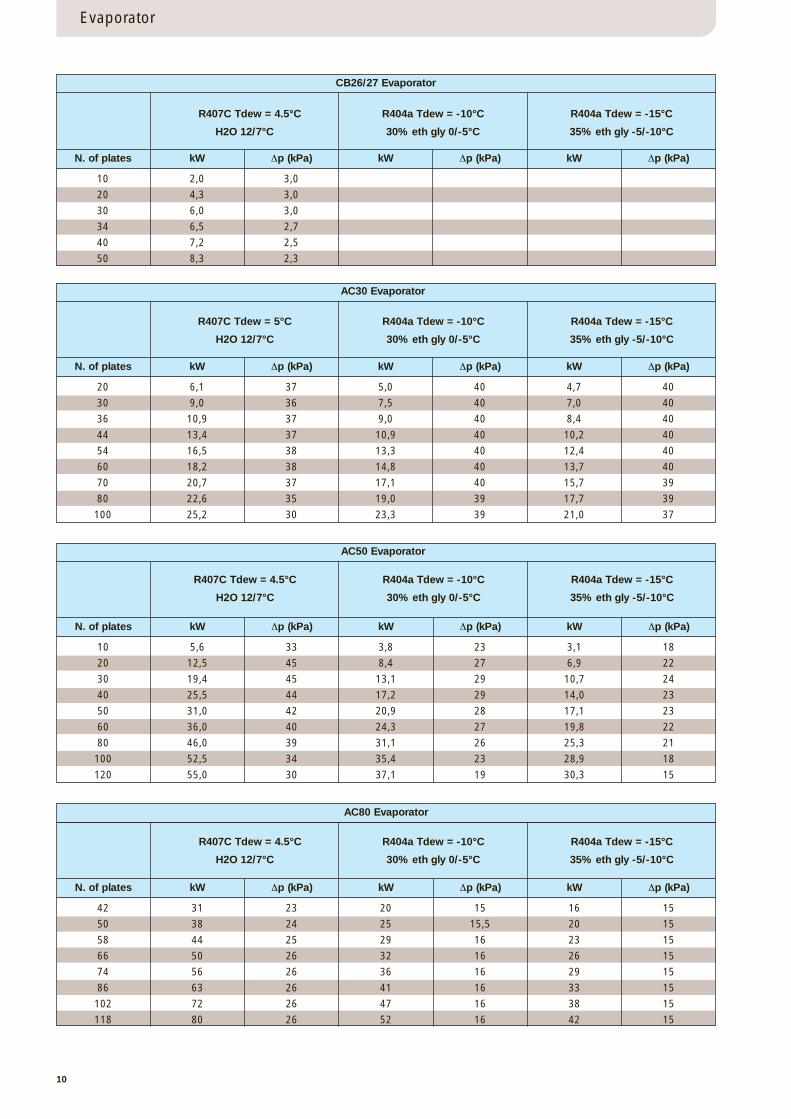
CB26/27 Evaporator
R407C Tdew = 4.5°C
H2O 12/7°C
R404a Tdew = -10°C
30% eth gly 0/-5°C
R404a Tdew = -15°C
35% eth gly -5/-10°C
N. of plates kW ∆p (kPa) kW ∆p (kPa) kW ∆p (kPa)
10 2,0 3,0
20 4,3 3,0
30 6,0 3,0
34 6,5 2,7
40 7,2 2,5
50 8,3 2,3
AC30 Evaporator
R407C Tdew = 5°C
H2O 12/7°C
R404a Tdew = -10°C
30% eth gly 0/-5°C
R404a Tdew = -15°C
35% eth gly -5/-10°C
N. of plates kW ∆p (kPa) kW ∆p (kPa) kW ∆p (kPa)
20 6,1 37 5,0 40 4,7 40
30 9,0 36 7,5 40 7,0 40
36 10,9 37 9,0 40 8,4 40
44 13,4 37 10,9 40 10,2 40
54 16,5 38 13,3 40 12,4 40
60 18,2 38 14,8 40 13,7 40
70 20,7 37 17,1 40 15,7 39
80 22,6 35 19,0 39 17,7 39
100 25,2 30 23,3 39 21,0 37
AC50 Evaporator
R407C Tdew = 4.5°C
H2O 12/7°C
R404a Tdew = -10°C
30% eth gly 0/-5°C
R404a Tdew = -15°C
35% eth gly -5/-10°C
N. of plates kW ∆p (kPa) kW ∆p (kPa) kW ∆p (kPa)
10 5,6 33 3,8 23 3,1 18
20 12,5 45 8,4 27 6,9 22
30 19,4 45 13,1 29 10,7 24
40 25,5 44 17,2 29 14,0 23
50 31,0 42 20,9 28 17,1 23
60 36,0 40 24,3 27 19,8 22
80 46,0 39 31,1 26 25,3 21
100 52,5 34 35,4 23 28,9 18
120 55,0 30 37,1 19 30,3 15
AC80 Evaporator
R407C Tdew = 4.5°C
H2O 12/7°C
R404a Tdew = -10°C
30% eth gly 0/-5°C
R404a Tdew = -15°C
35% eth gly -5/-10°C
N. of plates kW ∆p (kPa) kW ∆p (kPa) kW ∆p (kPa)
42 31 23 20 15 16 15
50 38 24 25 15,5 20 15
58 44 25 29 16 23 15
66 50 26 32 16 26 15
74 56 26 36 16 29 15
86 63 26 41 16 33 15
102 72 26 47 16 38 15
118 80 26 52 16 42 15
Evaporator
11
Evaporator
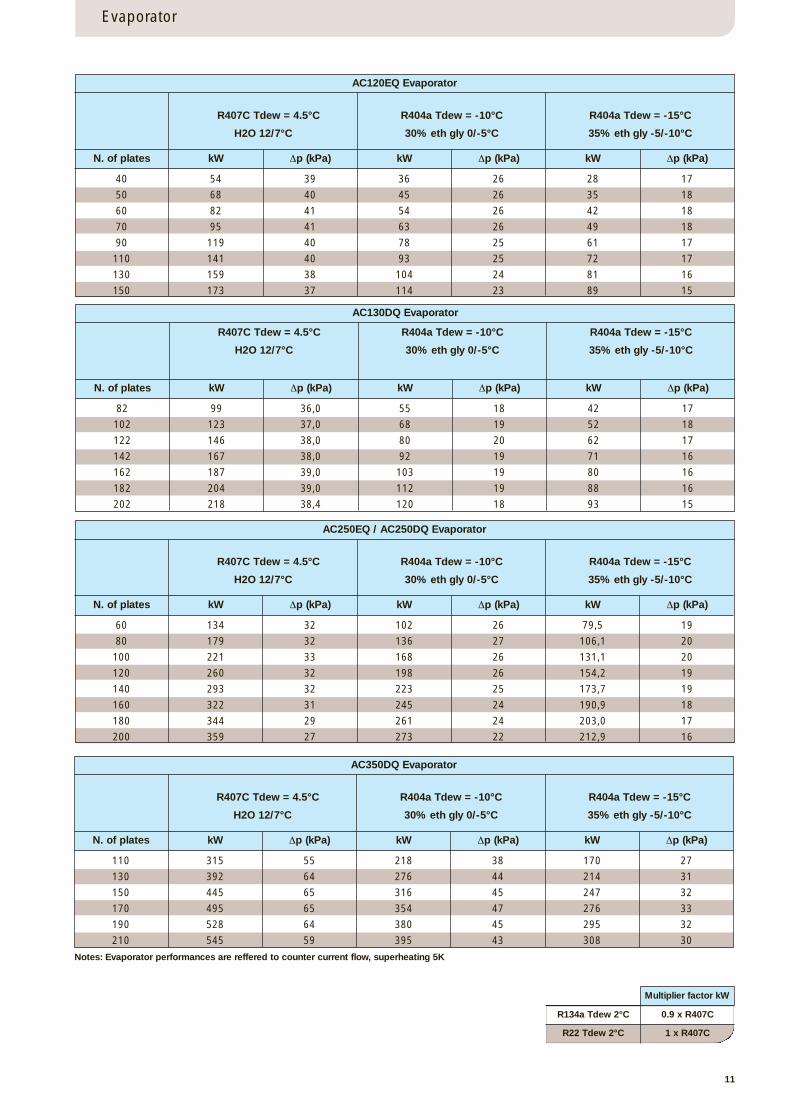
AC120EQ Evaporator
Multiplier factor kW
R134a Tdew 2°C 0.9 x R407C
R407C Tdew = 4.5°C
H2O 12/7°C
R404a Tdew = -10°C
30% eth gly 0/-5°C
R404a Tdew = -15°C
35% eth gly -5/-10°C
N. of plates kW ∆p (kPa) kW ∆p (kPa) kW ∆p (kPa)
40 54 39 36 26 28 17
50 68 40 45 26 35 18
60 82 41 54 26 42 18
70 95 41 63 26 49 18
90 119 40 78 25 61 17
110 141 40 93 25 72 17
130 159 38 104 24 81 16
150 173 37 114 23 89 15
Notes: Evaporator performances are reffered to counter current flow, superheating 5K
R22 Tdew 2°C 1 x R407C
AC130DQ Evaporator
R407C Tdew = 4.5°C
H2O 12/7°C
R404a Tdew = -10°C
30% eth gly 0/-5°C
R404a Tdew = -15°C
35% eth gly -5/-10°C
N. of plates kW ∆p (kPa) kW ∆p (kPa) kW ∆p (kPa)
82 99 36,0 55 18 42 17
102 123 37,0 68 19 52 18
122 146 38,0 80 20 62 17
142 167 38,0 92 19 71 16
162 187 39,0 103 19 80 16
182 204 39,0 112 19 88 16
202 218 38,4 120 18 93 15
AC250EQ / AC250DQ Evaporator
R407C Tdew = 4.5°C
H2O 12/7°C
R404a Tdew = -10°C
30% eth gly 0/-5°C
R404a Tdew = -15°C
35% eth gly -5/-10°C
N. of plates kW ∆p (kPa) kW ∆p (kPa) kW ∆p (kPa)
60 134 32 102 26 79,5 19
80 179 32 136 27 106,1 20
100 221 33 168 26 131,1 20
120 260 32 198 26 154,2 19
140 293 32 223 25 173,7 19
160 322 31 245 24 190,9 18
180 344 29 261 24 203,0 17
200 359 27 273 22 212,9 16
AC350DQ Evaporator
R407C Tdew = 4.5°C
H2O 12/7°C
R404a Tdew = -10°C
30% eth gly 0/-5°C
R404a Tdew = -15°C
35% eth gly -5/-10°C
N. of plates kW ∆p (kPa) kW ∆p (kPa) kW ∆p (kPa)
110 315 55 218 38 170 27
130 392 64 276 44 214 31
150 445 65 316 45 247 32
170 495 65 354 47 276 33
190 528 64 380 45 295 32
210 545 59 395 43 308 30
12
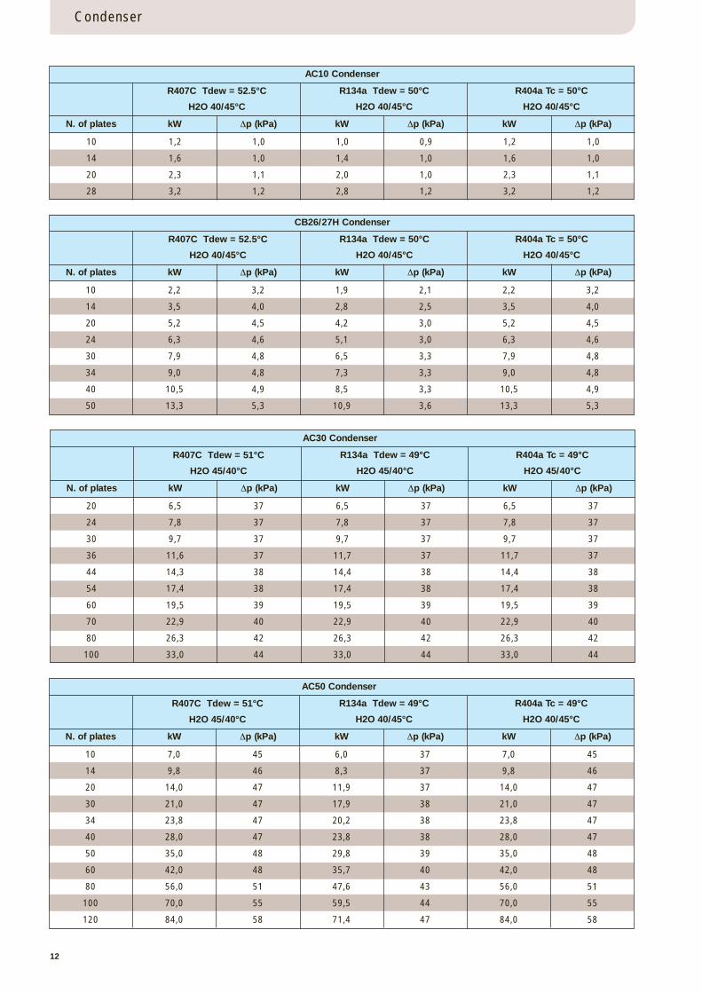
Condenser
AC10 Condenser
CB26/27H Condenser
R407C Tdew = 52.5°C
H2O 40/45°C
R134a Tdew = 50°C
H2O 40/45°C
R404a Tc = 50°C
H2O 40/45°C
N. of plates kW ∆p (kPa) kW ∆p (kPa) kW ∆p (kPa)
10 1,2 1,0 1,0 0,9 1,2 1,0
14 1,6 1,0 1,4 1,0 1,6 1,0
20 2,3 1,1 2,0 1,0 2,3 1,1
28 3,2 1,2 2,8 1,2 3,2 1,2
R407C Tdew = 52.5°C
H2O 40/45°C
R134a Tdew = 50°C
H2O 40/45°C
R404a Tc = 50°C
H2O 40/45°C
N. of plates kW ∆p (kPa) kW ∆p (kPa) kW ∆p (kPa)
10 2,2 3,2 1,9 2,1 2,2 3,2
14 3,5 4,0 2,8 2,5 3,5 4,0
20 5,2 4,5 4,2 3,0 5,2 4,5
24 6,3 4,6 5,1 3,0 6,3 4,6
30 7,9 4,8 6,5 3,3 7,9 4,8
34 9,0 4,8 7,3 3,3 9,0 4,8
40 10,5 4,9 8,5 3,3 10,5 4,9
50 13,3 5,3 10,9 3,6 13,3 5,3
AC30 Condenser
R407C Tdew = 51°C
H2O 45/40°C
R134a Tdew = 49°C
H2O 45/40°C
R404a Tc = 49°C
H2O 45/40°C
N. of plates kW ∆p (kPa) kW ∆p (kPa) kW ∆p (kPa)
20 6,5 37 6,5 37 6,5 37
24 7,8 37 7,8 37 7,8 37
30 9,7 37 9,7 37 9,7 37
36 11,6 37 11,7 37 11,7 37
44 14,3 38 14,4 38 14,4 38
54 17,4 38 17,4 38 17,4 38
60 19,5 39 19,5 39 19,5 39
70 22,9 40 22,9 40 22,9 40
80 26,3 42 26,3 42 26,3 42
100 33,0 44 33,0 44 33,0 44
AC50 Condenser
R407C Tdew = 51°C
H2O 45/40°C
R134a Tdew = 49°C
H2O 40/45°C
R404a Tc = 49°C
H2O 40/45°C
N. of plates kW ∆p (kPa) kW ∆p (kPa) kW ∆p (kPa)
10 7,0 45 6,0 37 7,0 45
14 9,8 46 8,3 37 9,8 46
20 14,0 47 11,9 37 14,0 47
30 21,0 47 17,9 38 21,0 47
34 23,8 47 20,2 38 23,8 47
40 28,0 47 23,8 38 28,0 47
50 35,0 48 29,8 39 35,0 48
60 42,0 48 35,7 40 42,0 48
80 56,0 51 47,6 43 56,0 51
100 70,0 55 59,5 44 70,0 55
120 84,0 58 71,4 47 84,0 58
13
Condenser
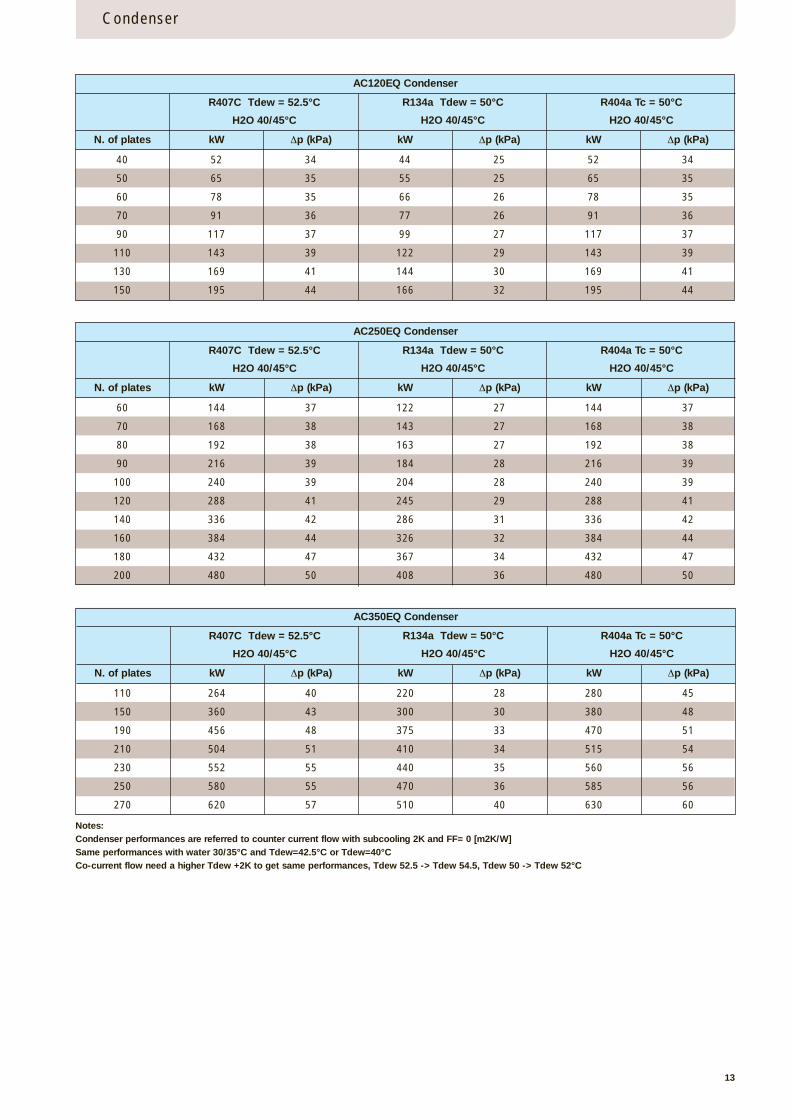
AC120EQ Condenser
R407C Tdew = 52.5°C
H2O 40/45°C
R134a Tdew = 50°C
H2O 40/45°C
R404a Tc = 50°C
H2O 40/45°C
N. of plates kW ∆p (kPa) kW ∆p (kPa) kW ∆p (kPa)
40 52 34 44 25 52 34
50 65 35 55 25 65 35
60 78 35 66 26 78 35
70 91 36 77 26 91 36
90 117 37 99 27 117 37
110 143 39 122 29 143 39
130 169 41 144 30 169 41
150 195 44 166 32 195 44
Notes:Condenser performances are referred to counter current flow with subcooling 2K and FF= 0 [m2K/W]Same performances with water 30/35°C and Tdew=42.5°C or Tdew=40°CCo-current flow need a higher Tdew +2K to get same performances, Tdew 52.5 -> Tdew 54.5, Tdew 50 -> Tdew 52°C
AC250EQ Condenser
R407C Tdew = 52.5°C
H2O 40/45°C
R134a Tdew = 50°C
H2O 40/45°C
R404a Tc = 50°C
H2O 40/45°C
N. of plates kW ∆p (kPa) kW ∆p (kPa) kW ∆p (kPa)
60 144 37 122 27 144 37
70 168 38 143 27 168 38
80 192 38 163 27 192 38
90 216 39 184 28 216 39
100 240 39 204 28 240 39
120 288 41 245 29 288 41
140 336 42 286 31 336 42
160 384 44 326 32 384 44
180 432 47 367 34 432 47
200 480 50 408 36 480 50
AC350EQ Condenser
R407C Tdew = 52.5°C
H2O 40/45°C
R134a Tdew = 50°C
H2O 40/45°C
R404a Tc = 50°C
H2O 40/45°C
N. of plates kW ∆p (kPa) kW ∆p (kPa) kW ∆p (kPa)
110 264 40 220 28 280 45
150 360 43 300 30 380 48
190 456 48 375 33 470 51
210 504 51 410 34 515 54
230 552 55 440 35 560 56
250 580 55 470 36 585 56
270 620 57 510 40 630 60
14
Accessories
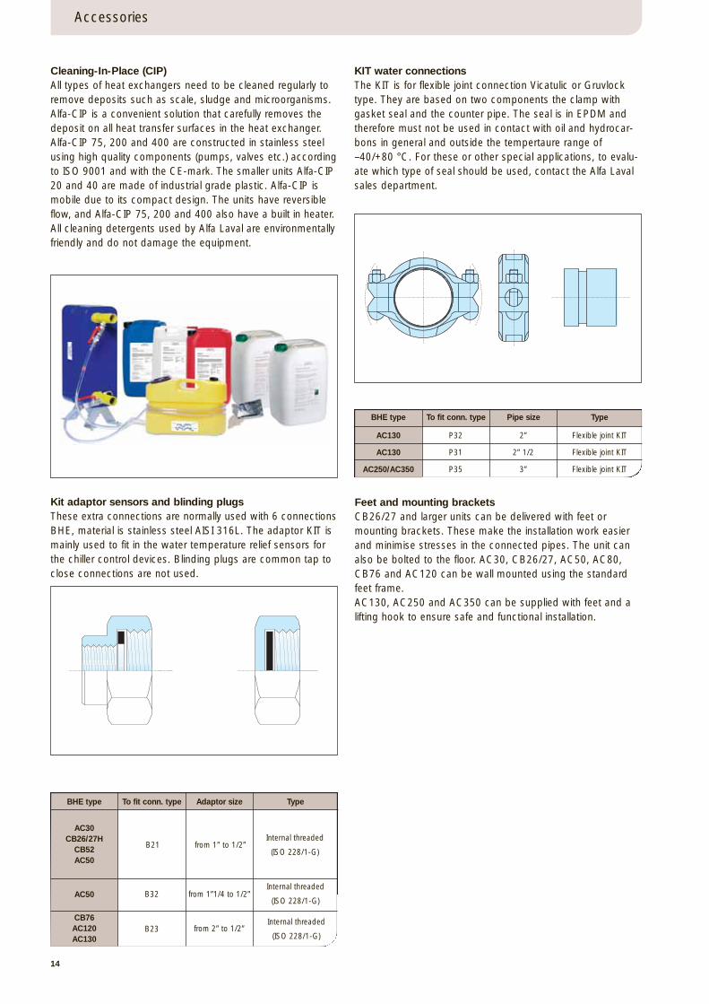
Cleaning-In-Place (CIP)All types of heat exchangers need to be cleaned regularly toremove deposits such as scale, sludge and microorganisms.Alfa-CIP is a convenient solution that carefully removes thedeposit on all heat transfer surfaces in the heat exchanger.Alfa-CIP 75, 200 and 400 are constructed in stainless steelusing high quality components (pumps, valves etc.) accordingto ISO 9001 and with the CE-mark. The smaller units Alfa-CIP20 and 40 are made of industrial grade plastic. Alfa-CIP ismobile due to its compact design. The units have reversibleflow, and Alfa-CIP 75, 200 and 400 also have a built in heater.All cleaning detergents used by Alfa Laval are environmentallyfriendly and do not damage the equipment.
Kit adaptor sensors and blinding plugsThese extra connections are normally used with 6 connectionsBHE, material is stainless steel AISI 316L. The adaptor KIT ismainly used to fit in the water temperature relief sensors forthe chiller control devices. Blinding plugs are common tap toclose connections are not used.
Feet and mounting bracketsCB26/27 and larger units can be delivered with feet ormounting brackets. These make the installation work easierand minimise stresses in the connected pipes. The unit canalso be bolted to the floor. AC30, CB26/27, AC50, AC80,CB76 and AC120 can be wall mounted using the standardfeet frame. AC130, AC250 and AC350 can be supplied with feet and alifting hook to ensure safe and functional installation.
KIT water connectionsThe KIT is for flexible joint connection Vicatulic or Gruvlocktype. They are based on two components the clamp withgasket seal and the counter pipe. The seal is in EPDM andtherefore must not be used in contact with oil and hydrocar-bons in general and outside the tempertaure range of–40/+80 °C. For these or other special applications, to evalu-ate which type of seal should be used, contact the Alfa Lavalsales department.
AC130
AC130
AC250/AC350
P32
P31
P35
2”
2” 1/2
3”
Flexible joint KIT
Flexible joint KIT
Flexible joint KIT
BHE type To fit conn. type Pipe size Type
BHE type To fit conn. type Adaptor size Type
B21 from 1” to 1/2”Internal threaded
(ISO 228/1-G)
B32 from 1”1/4 to 1/2”Internal threaded
(ISO 228/1-G)
B23Internal threaded
(ISO 228/1-G)from 2” to 1/2”
AC30CB26/27H
CB52AC50
AC50
CB76AC120AC130

Alfa Laval in briefAlfa Laval is a leading global provider of specialized products and engineeringsolutions.
Our equipment, systems and services are dedicated to assisting customers in optimizing the performance of theirprocesses. Time and time again.
We help them heat, cool, separateand transport products such as oil, water,chemicals, beverages, foodstuff, starch and pharmaceuticals.
Our worldwide organization worksclosely with customers in almost 100countries to help them stay ahead.
How to contact Alfa LavalUp-to-date Alfa Laval contact details for all countries are always available on our website at www.alfalaval.com
ECR00010EN 0602
Alfa Laval reserves the right to change specifications without prior notification
© 2004 Alfa Laval
EQ
UA
LAN
CE
R a
nd D
UA
LAC
ED
are
tra
dem
arks
ow
ned
by
Alfa
Lav
al C
orp
orat
e A
B.


