Dual-line lubrication systems - SKF...Applications SKF dual-line lubrication systems are developed...
88
Product catalogue Dual-line lubrication systems
Transcript of Dual-line lubrication systems - SKF...Applications SKF dual-line lubrication systems are developed...
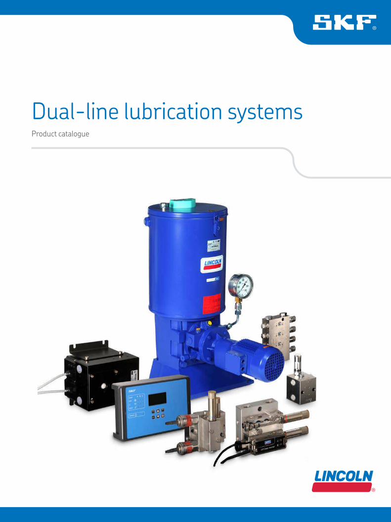
Product catalogue
Dual-line lubrication systems

Intr
oduct
ion
Table of content
Two leading brands 4
Lubricants suitable for lubrication systems 5
System description 6
Applications 7
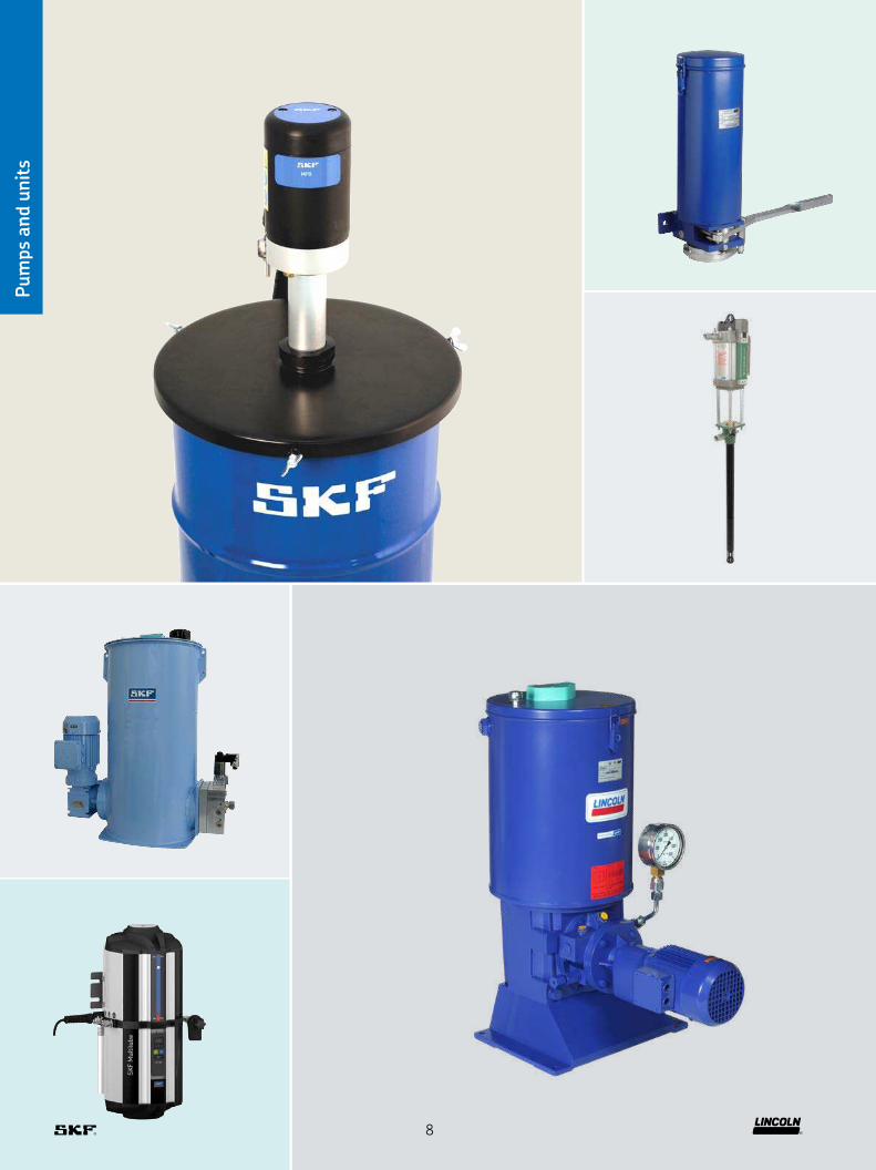
Overview of pump units 9
HJ 2 10
Multilube 12
ZPU 01/02 14
FK 16
ZPU 08 / 14 / 24 18
E-PUMP 20
MPB 22
Lubrigun 24
PowerMaster III 26
Overview of metering devices 29
VSKH / VSKV 30
VSG 34
VSL 38
SGA / SG 42
Overview of valves 47
DU 1 48
MP 2 49
E-VALV 50
Maxilube 52
EMU 3 54
EMU 3 55
CLV-2 56
E-VALV-S 58
WSE 60
Overview of pressure sensors 63
DSB 1 64
EDW 66
DW 67
BPSG PTA-MOD 68
DDS 50/1 69
DPC 1 70
Overview of control units 73
LMC 2 74
LMC 301 75
ST-1240 76
ST-2240-LUB 77
LRM 2 78
Index 80
2
Intr
oduct
ionIntroduction 2
Pumps units 9
Metering devices 29
Pressure sensors 63
Navigation
Control units 73
Valves 47
3
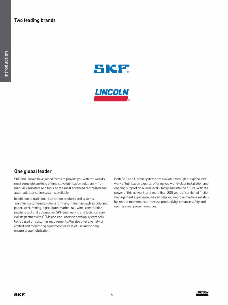
Two leading brands
SKF and Lincoln have joined forces to provide you with the world’s
most complete portfolio of innovative lubrication solutions – from
manual lubricators and tools, to the most advanced centralized and
automatic lubrication systems available
In addition to traditional lubrication products and systems,
we offer customized solutions for many industries such as pulp and
paper, steel, mining, agriculture, marine, rail, wind, construction,
machine tool and automotive SKF engineering and technical spe-
cialists partner with OEMs and end-users to develop system solu-
tions based on customer requirements We also offer a variety of
control and monitoring equipment for ease of use and to help
ensure proper lubrication
Both SKF and Lincoln systems are available through our global net-
work of lubrication experts, offering you world-class installation and
ongoing support on a local level – today and into the future With the
power of this network, and more than 200 years of combined friction
management experience, we can help you improve machine reliabil-
ity, reduce maintenance, increase productivity, enhance safety and
optimise manpower resources
One global leader
Intr
oduct
ion
4

Oil and luid greaseThe viscosity is an expression of a luid’s internal friction Oils are classiied in ISO VG
viscosity classes from 2 to 3 200 NLGI grade 000, 00 and 0 greases are called luid
greases Different types of oils are available, including mineral oils, organic oils and
synthetic oils A compatibility check is recommended prior to using any oil with
SKF lubrication systems
GreaseGreases are consistent lubricants (NLGI grade 1–6) They are soft to hard, triple-
component mixtures of a base oil as the lubricating luid, a thickening agent and
additives In most instances, greases of NLGI grade 1 up to 3 are suitable for use
in a lubrication system A compatibility check should be made prior to using any
grease with SKF lubrication systems
Intr
oduct
ion
ISO VG 3 10 32 100 320 680 1 500 2 200 3 200
N LGI grades 000 00 0 1 2 3 4
fluid semi-fluid non-fluid
OilFluid
greaseGrease
Lubricants suitable for lubrication systems
5

Dual-line lubrication systems
SKF dual-line systems can be used on large systems with dispersed
lubrication points that require varying lubrication quantities These
systems utilize two main lines that are supplied alternately with
lubricant from a high-pressure pump via a change-over valve at up
to 400 bar (5 800 psi) Branch lines, along the main lines, are con-
nected with dual-line metering devices to supply a large volume of
lubricant to the lubrication points Within large dual-line systems,
end-of-line pressure switches are used to control and monitor the
system These lexible systems are simple to design and can be
extended or reduced easily by installing additional metering devices
or by removing them A redesign of the system is not required Dual-
line metering devices can be combined with downstream progressive
metering devices to increase the total number of lubrication points
receiving small lubricant amounts SKF offers dual-line systems that
can dispense a precise, metered amount of lubricant to up to 2 000
lubrication points over long distances up to 120 m (131 yd) and more,
depending on case values
Even if one pair of outlets becomes blocked inside one metering
device, SKF dual-line systems provide suficient lubrication for the
rest of the system’s lubrication points Lubricant volume can be
metered individually for each pair of outlets and can be monitored
visually or electrically
The function principle of the dual-line systems consists of two
half-cycles In the irst half-cycle, the lubricant is pumped into the
main line (A) and the main line (B) is connected to the relief line The
lubricant, which is conducted by the change-over valve, is supplied to
the metering devices The pistons of the metering devices are moved
into their adjusted end positions, thus dispensing an exact, metered
quantity of grease Once all metering devices have dispensed their
lubricant to the consumption point, the system is hydraulically
closed, which causes the pressure in main line (A) to rise until to the
preset pressure at the end-of-line pressure switch (mounted in the
main lines prior the last metering device) is reached This pressure
switch then signals an electric pulse to the control unit, witch turns
the pump off and signals the change-over valve to relieve main line
(A), and the pause time starts At this stage, half of the lubrication
points in the system have been lubricated
In the second half-cycle, main line (B) is pressurized and the cycle
continues as before
System description
Intr
oduct
ion
System video
6

Applications
SKF dual-line lubrication systems are developed for use with oil,
semi-luid grease and hard grease up to NLGI grade 2 Harder
greases of NLGI grade 3 only can be used if so determined after con-
sultation SKF dual-line lubrication systems are suitable for a variety
of applications, including heavy industry, metal working plants, pulp
and paper production, mining, mineral processing, power plants,
cement factories, steel works and more These reliable systems
operate effectively in the harsh conditions associated with these
industries, including potentially high lubrication-point back pressure,
dirty, wet or humid environments and low temperatures In
troduct
ion
7
Pum
ps
and u
nit
s
8
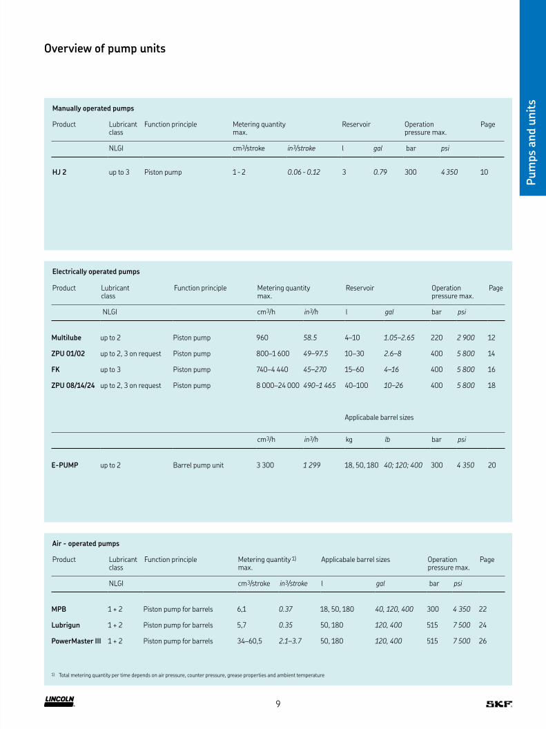
Manually operated pumps
Product Lubricant class
Function principle Metering quantity max
Reservoir Operation pressure max
Page
NLGI cm3/stroke in3/stroke l gal bar psi
HJ 2 up to 3 Piston pump 1 - 2 0.06 - 0.12 3 0.79 300 4 350 10
Overview of pump units
Pum
ps
and u
nit
s
Electrically operated pumps
Product Lubricant class
Function principle Metering quantity max
Reservoir Operation pressure max
Page
NLGI cm3/h in3/h l gal bar psi
Multilube up to 2 Piston pump 960 58.5 4–10 1.05–2.65 220 2 900 12
ZPU 01/02 up to 2, 3 on request Piston pump 800–1 600 49–97.5 10–30 2.6–8 400 5 800 14
FK up to 3 Piston pump 740–4 440 45–270 15–60 4–16 400 5 800 16
ZPU 08/14/24 up to 2, 3 on request Piston pump 8 000–24 000 490–1 465 40–100 10–26 400 5 800 18
Applicabale barrel sizes
cm3/h in3/h kg lb bar psi
E-PUMP up to 2 Barrel pump unit 3 300 1 299 18, 50, 180 40; 120; 400 300 4 350 20
Air - operated pumps
Product Lubricant class
Function principle Metering quantity 1)
max Applicabale barrel sizes Operation
pressure max Page
NLGI cm3/stroke in3/stroke l gal bar psi
MPB 1 + 2 Piston pump for barrels 6,1 0.37 18, 50, 180 40, 120, 400 300 4 350 22
Lubrigun 1 + 2 Piston pump for barrels 5,7 0.35 50, 180 120, 400 515 7 500 24
PowerMaster III 1 + 2 Piston pump for barrels 34–60,5 2.1–3.7 50, 180 120, 400 515 7 500 26
1) Total metering quantity per time depends on air pressure, counter pressure, grease properties and ambient temperature
9

Pum
p u
nit
s
NOTE Further technical information, technical drawings,
accessories, spare parts or product function descriptions
available on SKF com/lubrication:
16966 EN, 951-170-232
3D
skf-lubrication partcommunity com/3d-cad-models
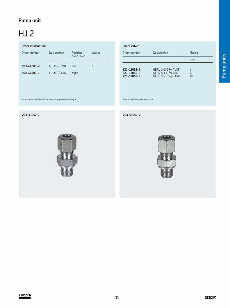
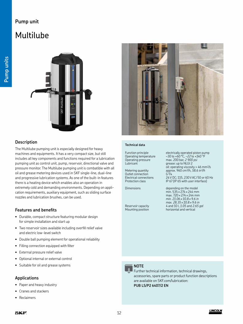
Pump unit
HJ 2
Technical data
Function principle manually operated pump unitOutlets 1Lubricant output per stroke 1–2 cm3, 0.06–0.12 in3Lubricant grease: up to NLGI 3,
depending on operating temperature oil: with a viscosity minimum 150 mm2/s at operating temperature
Operating temperature –20 to +70 °C, –4 to +160 °FOperating pressure max 300 bar, 4 350 psiHand force at max pressure 300 NReservoir capacity 3 l, 0.8 gal
Outlet connection G 1/4Dimensions 410 × 135 × 393 mm
16.1 × 5.5 × 15.5 inMounting position vertical
Description
The manually operated HJ 2 pump unit was developed to provide
lubricant to points that do not require continuous lubrication
Comprised of two supply pistons and a 3 liter (0.8 gal) reservoir
with an integrated stirring device, this robust pump unit operates
effectively, even at low temperatures Operating pressure is
300 bar (4 350 psi)
Features and beneits
• Suitable for use with dual-line or
progressive systems
• Dispenses greases up to NLGI 3
• Available with left- or right-hand lever
Applications
• Metal forming machines
• Roll straighteners
• Tyre heating presses
• Harbor cranes
• Ski lifts
NOTE Further technical information, technical drawings,
accessories, spare parts or product function descriptions
are available on SKF com/lubrication
10
Pum
p u
nit
s
Pump unit
HJ 2
Order information
Order number Designation Position hand lever
Outlet
603-41200-2 HJ 2 L–3 XYN left 1
603-41200-1 HJ 2 R–3 XYN right 1
Note: for two outlet versions refer to progressive catalogue
Check valves
Order number Designation Tube ø
mm
223-13052-1 GERV 6-S G 1/4 AVCF 6223-13052-2 GERV 8-L G 1/4 AVCF 8223-13052-3 GERV 10-L G 1/4 AVCF 10
Note: must be ordered with pump
223-13052-1 223-13052-2
11
Pum
p u
nit
s
Technical data
Function principle electrically operated piston pumpOperating temperature –30 to +60 °C, –22 to +140 °FOperating pressure max 200 bar, 2 900 psi Lubricant grease: up to NLGI 2
oil: operating viscosity > 46 mm2/sMetering quantity approx 960 cm3/h, 58.6 in3/hOutlet connection G 1/4Electrical connections 24 V DC; 115, 230 V AC / 50 or 60 HzProtection class IP 67 (IP 65 with user interface)
Dimensions depending on the model min 535 × 274 × 244 mm max 720 × 274 × 244 mmmin. 21.06 × 10.8 × 9.6 in max. 28.35 × 10.8 × 9.6 in
Reservoir capacity 4 and 10 l, 1.05 and 2.65 galMounting position horizontal and vertical
Pump unit
Multilube
Description
The Multilube pumping unit is especially designed for heavy
machines and equipments It has a very compact size, but still
includes all key components and functions required for a lubrication
pumping unit as control unit, pump, reservoir, directional valve and
pressure monitor The Multilube pumping unit is combatible with all
oil and grease metering devices used in SKF single-line, dual-line
and progressive lubrication systems As one of the built-in features
there is a heating device which enables also an operation in
extremely cold and demanding environments Depending on appli-
cation requirements, auxiliary equipment, such as sliding surface
nozzles and lubrication brushes, can be used
Features and beneits
• Durable, compact structure featuring modular design
for simple installation and start up
• Two reservoir sizes available including overill relief valve
and electric low-level switch
• Double ball pumping element for operational reliability
• Filling connection equipped with ilter
• External pressure relief valve
• Optional internal or external control
• Suitable for oil and grease systems
Applications
• Paper and heavy industry
• Cranes and stackers
• Reclaimers
NOTE Further technical information, technical drawings,
accessories, spare parts or product function descriptions
are available on SKF com/lubrication:
PUB LS/P2 6407/2 EN
12
Pum
p u
nit
s
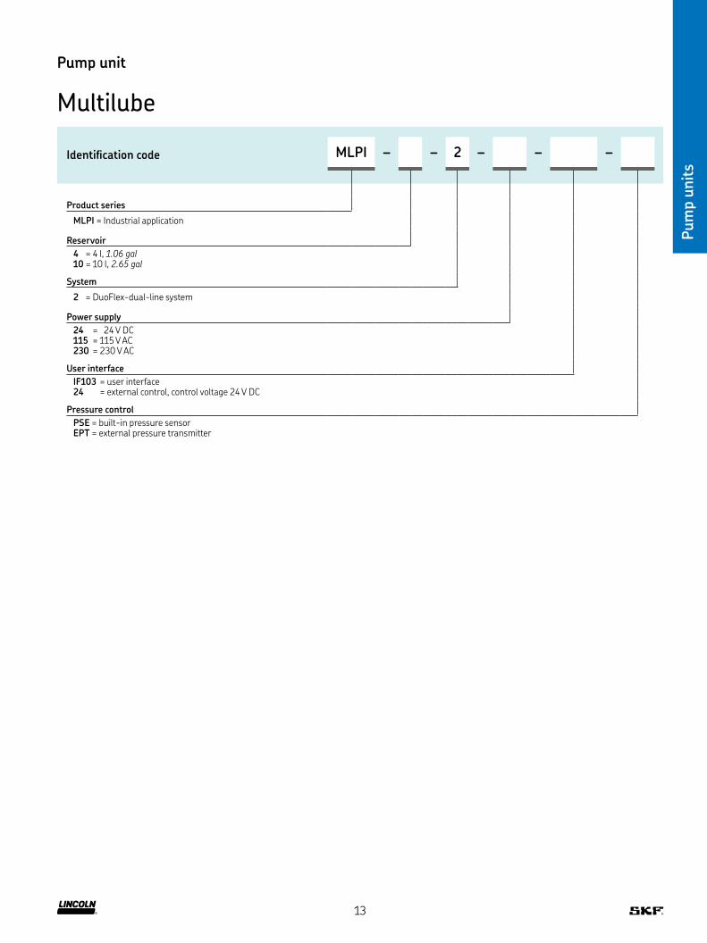
Pump unit
Multilube
Identiication code MLPI – – 2 – – –
Product series
MLPI = Industrial application
Reservoir
4 = 4 l, 1.06 gal10 = 10 l, 2.65 gal
System
2 = DuoFlex-dual-line system
Power supply
24 = 24 V DC115 = 115 V AC230 = 230 V AC
User interface
IF103 = user interface 24 = external control, control voltage 24 V DC
Pressure control
PSE = built-in pressure sensor EPT = external pressure transmitter
13
Pum
p u
nit
s
Technical data
Function principle electrically operated piston pump unitOperating temperature –20 to +70 °C; –4 to +158 °FOperating pressure M100, M490: max 350 bar, 5 075 psi
M049: max 400 bar, 5 800 psiLubricant grease: up to NLGI 2, NLGI 3 on request
oil: with a viscosity of min 40 mm2/s at operating temperature
Metering quantity 1) ZPU 01: 800 cm3/h, 48.8 in3/hZPU 02: 1 600 cm3/h, 97.5 in3/hZPU 02-M049: 3 200 cm3/h, 195.2 in3/h
Reservoir capacity 10 or 30 l, 2 6 or 8 galMain line connection 2) model F: for tube 10 mmElectrical connection 380–420 V AC/50 Hz,
440–480 V AC/60 HzProtection class IP 65Dimensions depending on the model:
min 514 × 379 × 317 mm max 754 × 431 × 337 mm min. 20.25 × 15 × 12.5 in max. 29.75 × 17 × 15 in
Dimensions low level sensor 30 × 125 × 65 mm1.2 × 5 × 2.75 in
Mounting position vertical
Pump unit
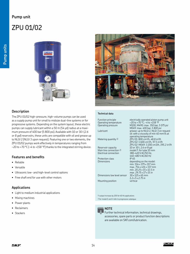
ZPU 01/02
Description
The ZPU 01/02 high-pressure, high-volume pumps can be used
as a supply pump unit for small to midsize dual-line systems or for
progressive systems Depending on the system layout, these electric
pumps can supply lubricant within a 50 m (54 yd) radius at a maxi-
mum pressure of 400 bar (5 800 psi) Available with 10 or 30 l (2.6
or 8 gal) reservoirs, these units are compatible with oil and grease up
to NLGI 2 (NLGI 3 upon request) Featuring one or two elements, the
ZPU 01/02 pumps work effectively in temperatures ranging from
–20 to +70 °C (–4 to +158 °F) thanks to the integrated stirring device
Features and beneits
• Reliable
• Versatile
• Ultrasonic low- and high-level control options
• Free shaft end for use with other motors
Applications
• Light to medium industrial applications
• Mixing machines
• Power plants
• Reclaimers
• Stackers
NOTE Further technical information, technical drawings,
accessories, spare parts or product function descriptions
are available on SKF com/lubrication
1) output increase by 20% for 60 Hz applications
2) for model E and V refer to progressive catalogue
14
Pum
p u
nit
s
Pump unit
ZPU 01/02
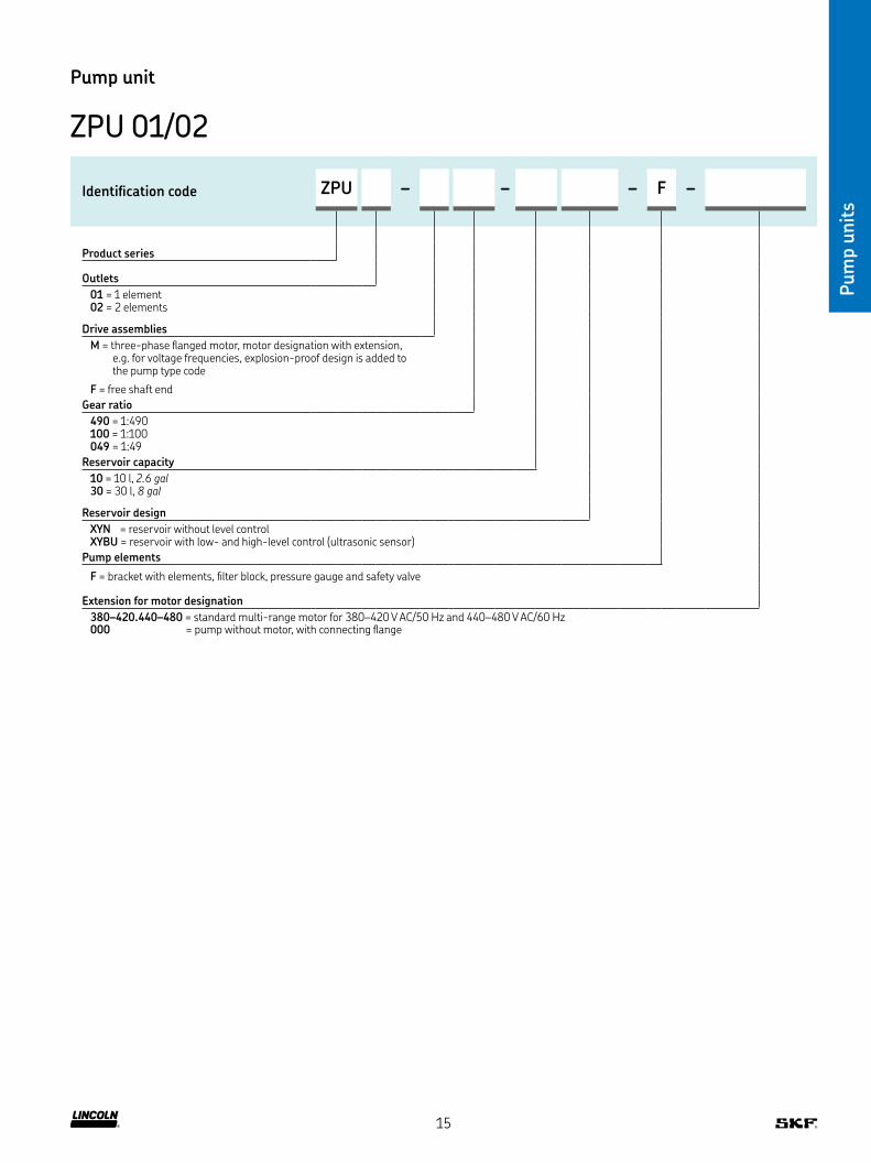
Identiication code ZPU – – – F –
Product series
Outlets
01 = 1 element 02 = 2 elements
Drive assemblies
M = three-phase langed motor, motor designation with extension, e g for voltage frequencies, explosion-proof design is added to the pump type code
F = free shaft end
Gear ratio
490 = 1:490 100 = 1:100 049 = 1:49
Reservoir capacity
10 = 10 l, 2.6 gal30 = 30 l, 8 gal
Reservoir design
XYN = reservoir without level control XYBU = reservoir with low- and high-level control (ultrasonic sensor)
Pump elements
F = bracket with elements, ilter block, pressure gauge and safety valve
Extension for motor designation
380–420 440–480 = standard multi-range motor for 380–420 V AC/50 Hz and 440–480 V AC/60 Hz000 = pump without motor, with connecting lange
15
Pum
p u
nit
s
Technical data
Function principle radial piston pump unitOperating temperature –25 to +60 °C; –13 to +140 °F
with control cabinet: 0 to +60 °C; +32 to +140 °F
Lubricant grease: NLGI 2 and 3oil: mineral or enviromentally compatible oils from ISO VG 46,operating viscosity ≥ 50 mm2/s
Operating pressure max 400 bar, max. 5 800 psiMetering quantity see order number conigurator next pageReservoir 15, 30 and 60 l; 4, 8 and 16 galOutlet connection G 1/2Electrical connection motor: 230/400 V AC, 50 Hz
solenoid valves, sensor: 24 V DCProtection class IP 55, with control cabinet: IP 54Dimensions depending on the model
598 × 335 × 990 mm 23.5 × 13.2 × 39 in
Mounting position vertical
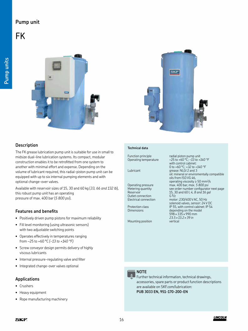
Pump unit
FK
Description
The FK grease lubrication pump unit is suitable for use in small to
midsize dual-line lubrication systems Its compact, modular
construction enables it to be retroitted from one system to
another with minimal effort and expense Depending on the
volume of lubricant required, this radial-piston pump unit can be
equipped with up to six internal pumping elements and with
optional change-over valves
Available with reservoir sizes of 15, 30 and 60 kg (33, 66 and 132 lb),
this robust pump unit has an operating
pressure of max 400 bar (5 800 psi)
Features and beneits
• Positively driven pump pistons for maximum reliability
• Fill level monitoring (using ultrasonic sensors)
with two adjustable switching points
• Operates effectively in temperatures ranging
from –25 to +60 °C (–13 to +140 °F)
• Screw conveyor design permits delivery of highly
viscous lubricants
• Internal pressure-regulating valve and ilter
• Integrated change-over valves optional
Applications
• Crushers
• Heavy equipment
• Rope manufacturing machinery
NOTE Further technical information, technical drawings,
accessories, spare parts or product function descriptions
are available on SKF com/lubrication:
PUB 3033 EN, 951-170-200-EN
16

Pum
p u
nit
s
Pump unit
FK
Identiication code FK – 1M 04 – – – AF 07
Product series FK
Version
2 = Unit for dual-line centralized lubrication systems with change-over valves
3 = Unit for dual-line centralized lubrication systems without change-over valves
Reservoir capacity
15 = 15 l; 4 gal 30 = 30 l; 8 gal60 = 60 l; 16 gal
Lubricant level monitoring
X = without lubricant level monitoring U2 = Ultrasonic sensor with 2 switching points
Drive type 1M
Gear ratio
04 = 40:1
Delivery volume per h
1 = 740 cm3/h; 45 in3/h3 = 2 220 cm3/h; 156 in3/h 5 = 3 700 cm3/h; 226 in3/h
2 = 1 480 cm3/h; 90 in3/h 4 = 2 960 cm3/h; 180 in3/h6 = 4 440 cm3/h; 270 in3/h
Pressure-regulating valve, factory-set to
200 = 200 bar; 2 900 psi300 = 300 bar; 4 350 psi400 = 400 bar; 5 800 psi
Pressure gauge
/ = without pressure gauge MA = 1 × pressure gauge M2 = 2 × pressure gauge
Filler socket/Screw cap
0 = without iller socket 1 = with iller socket
2 = without iller socket, with screw cap 3 = with iller socket and screw cap
Version key
0001 = basic design 4001 = basic design with control cabinet and control unit
Motor data 1)
AF = motor speed 1 500 min-1, rated voltage 230/400 V AC, 50 Hz
Motor protection class
07 = IP 55 F as standard
1) other speciications available on request
17

Pum
p u
nit
s
Technical data
Function principle electrically operated piston pumpDrive speed depending on model 60 – 180 min-1
Operating temperature –20 to +80 °C, –4 to +176 °FLubricant grease: up to NLGI 2, NLGI 3 on request
oil: with a viscosity of min 20 mm2/sMetering quantity 1) ZPU 08: 8 000 cm3/h, 488 in3/h
ZPU 14: 14 000 cm3/h, 855 in3/h ZPU 24: 24 000 cm3/h, 1 465 in3/h
Operating pressure max 400 bar, 5 800 psiReservoir capacity 40 or 100 l, 10 or 26 galMain line connection G 3/4 femaleElectrical connection 380–415V AC/50Hz,
420–480 V AC/60 Hz, 500 V AC/50 HzProtection class IP 65Dimensions depending on the model
min 760 × 670 × 410 mm max 975 × 825 × 500 mm min. 30 × 26 × 16 in max. 38.5 × 32.5 × 20 in
Mounting position vertical
Pump unit
ZPU 08 / 14 / 24
Description
The ZPU 08/14/24 pumps are used primarily in dual-line systems
or as supply pumps and have a maximum operating pressure of
400 bar (5 800 psi) Depending on the system layout, these electric
pumps can supply lubricant at distances of up to 120 meters
(131 yd) and more Available with a 40 or 100 l (10 or 26 gal) reser-
voir, the pressure ZPU 08/14/24 pumps come standard with a pres-
sure relief valve, check valve, lubricant ilter and a pressure gauge
These robust units operate effectively at temperatures ranging from
–20 to +80 °C (–4 to +176 °F) thanks to the integrated stirring device
Features and beneits
• Reliable
• Simple to service
• Three options for high lubricant output
• Ultrasonic low- and high-level control options
• Built-in lubricant ilter
Applications
• Cement plants
• Steel mills
• Power plants
• Mining
• Large machines
NOTE Further technical information, technical drawings,
accessories, spare parts or product function descriptions
are available on SKF com/lubrication
1) output increase by 20% for 60 Hz applications
18
Pum
p u
nit
s
Pump unit
ZPU 08 / 14 / 24
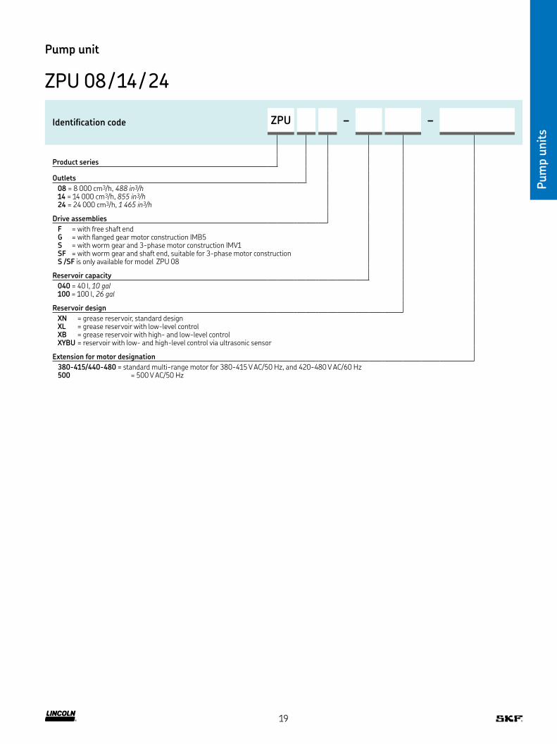
Identiication code ZPU – –
Product series
Outlets
08 = 8 000 cm3/h, 488 in3/h14 = 14 000 cm3/h, 855 in3/h24 = 24 000 cm3/h, 1 465 in3/h
Drive assemblies
F = with free shaft end G = with langed gear motor construction IMB5 S = with worm gear and 3-phase motor construction IMV1 SF = with worm gear and shaft end, suitable for 3-phase motor construction S /SF is only available for model ZPU 08
Reservoir capacity
040 = 40 l, 10 gal100 = 100 l, 26 gal
Reservoir design
XN = grease reservoir, standard design XL = grease reservoir with low-level control XB = grease reservoir with high- and low-level control XYBU = reservoir with low- and high-level control via ultrasonic sensor
Extension for motor designation
380-415/440-480 = standard multi-range motor for 380-415 V AC/50 Hz, and 420-480 V AC/60 Hz500 = 500 V AC/50 Hz
19

Pum
p u
nit
s
Technical data
Function principle electrically operated pumpOutlets 1Number of pump elements 4Metering quantity 55 g/min; 0.3880136 oz/minOperating temperature –30 to +70 °C, -20 to 160 °FOperating pressure max 240 bar, 3 480 psiLubricant grease up to NLGI 2
oil up to 1 000 mm2/sSupply voltage 20–32 V DCPower consumption 150 WHeater 40W / 24V, heater resistor
for pump elements in ECO modelsDisplay LED’s 5 yellow, 1 green, 1 redDrum capacity 18, 50 and 180 kg, 40, 120 or 400 lb
drum not includedPressure sensor 50-240 bar adjustable in 25 bar steps
725.1 to 3480.9 psi in 362.6 psi stepsProtection class IP 65Dimensions depending on the model
min 400 × 400 × 800 mm max 400 × 400 × 1 300 mmmin. 15.75 × 15.75 × 31.49 in max. 15.75 × 15.75 × 51.18 in
Mounting position vertical
Pump unit
E-PUMP
Description
The electrical barrel pumping unit E-PUMP is a versatile barrel
pump and it is especially designed for pumping oil or grease lubri-
cants up to NLGI grade 2 into a centralized lubrication system When
equipped with a change-over valve unit, as E-VALV e g or a shut-off
valve as E-VALVE-S e g it can be used either in single-line, dual-line
or progressive lubrication systems A complete pumping center con-
sists of a pumping unit and a lid set EPUMP-XXX-ECO coding is
referring to ECO lid sets (descending pump head with follower plate),
which are suitable for greases in NLGI grades 1 and 2 while EPUMP-
XXX-STA coding is referring to STA lid sets (pump head always at
barrel bottom), which are suitable for oil or greases in NLGI 0, 00 and
000 classes To run E-PUMP accurately in dual-line lubrication sys-
tems an additional change-over valve needs to be implemented
Features and beneits
• EPUMP models relecting typical and often used barrel sizes
• Compact electrically operated pump for applications where no
air supply is available
• An internal pressure control and a heating element secure the
pump’s function in high-pressure conditions and cold climates
Applications
• Heavy industries (paper, steel and other process industries)
• Mining and mineral processing
• Machinery workshops
• Food and beverage
• Cement industry
20

Pum
p u
nit
s
Pump unit
E-PUMP
Lid sets for grease barrels
Order number Designation Lubricant for barrel size
kg lb
12381280 E-LIDSET-1/8-ECO Grease 18 40
12381285 E-LIDSET-1/4-ECO Grease 50 120
12381290 E-LIDSET-1/1-ECO Grease 180 400
Lid sets for grease barrels
Order information
Order number Designation Lubricant Control Suitable barrel size
kg lb
12375180 SKF-EPUMP-1/8-ECO-24-CC Grease up to NLGI 2 external control unit 18 40
12375100 SKF-EPUMP-1/4-ECO-24-CC Grease up to NLGI 2 external control unit 50 120
12375020 SKF-EPUMP-1/1-ECO-24-CC Grease up to NLGI 2 external control unit 180 400
Accessories
21
Pum
p u
nit
s
Technical data
Function principle air operated piston pump for barrels
Operating temperature –10 to +55 °C, 14 to 131 °FOperating pressure max 300 bar, 4 350 psiPressure ratio 1:65Pressure air supply 2 to 4,5 bar, 29 to 65 psiAir consumption max 300 l/min; 80 gal/minLubricant grease up to NLGI 2
oil up to 10 000 mm2/sMetering quantity per cycle 1) 6,1 cm3; 0.37 in3
Drum capacity 18, 50 and 180 kg, 40, 120 or 400 lb drum not included
Protection class IP 65Dimensions depending on the model
min 650 × 130 × 130 mm max 920 × 130 × 130 mmmin. 25.6 × 5.11 × 5.11 in max. 36.22 × 5.11 × 5.11 in
Mounting position vertical
Pump unit
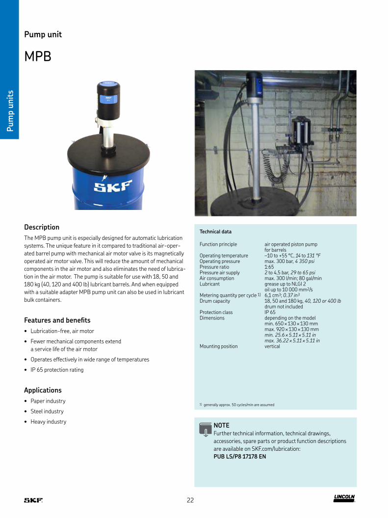
MPB
Description
The MPB pump unit is especially designed for automatic lubrication
systems The unique feature in it compared to traditional air-oper-
ated barrel pump with mechanical air motor valve is its magnetically
operated air motor valve This will reduce the amount of mechanical
components in the air motor and also eliminates the need of lubrica-
tion in the air motor The pump is suitable for use with 18, 50 and
180 kg (40, 120 and 400 lb) lubricant barrels And when equipped
with a suitable adapter MPB pump unit can also be used in lubricant
bulk containers
Features and beneits
• Lubrication-free, air motor
• Fewer mechanical components extend
a service life of the air motor
• Operates effectively in wide range of temperatures
• IP 65 protection rating
Applications
• Paper industry
• Steel industry
• Heavy industryNOTE Further technical information, technical drawings,
accessories, spare parts or product function descriptions
are available on SKF com/lubrication:
PUB LS/P8 17178 EN
1) generally approx 50 cycles/min are assumed
22
Pum
p u
nit
s
Pump unit
MPB
Air regulator unit
Order number Designation
12382666 MAX-V2-SET-MPB
Lid sets
Order number Designation Suitable barrel size
kg lb
12381383 MAXV2-LIDSET-1/8-ECO-MPB 18 4012381382 MAXV2-LIDSET-1/4-ECO-MPB 50 12012381381 MAXV2-LIDSET-1/1-ECO-MPB 180 400
12381386 MAXV2-LIDSET-1/8-STA-MPB 18 4012381385 MAXV2-LIDSET-1/4-STA-MPB 50 12012381384 MAXV2-LIDSET-1/1-STA-MPB 180 400
Lid sets
Air regulator unit
Order information
Order number Designation Suitable barrel size
kg lb
12371702 SKF-MPB-PUMP-1/8 18 40
12371701 SKF-MPB-PUMP-1/4 50 120
12381700 SKF-MPB-PUMP-1/1 180 400
Accessories
23
Pum
p u
nit
s
Technical data
Function principle air-operated piston pump unit for barrels
Operating temperature –34 to +93 °C, –30 to +200°FOperating pressure max 515 bar, 7 500 psiLubricant NLGI 1 and 2Cycles per minute 1) max 120Metering quantity per cycle 5,7 cm3, 0.35 in3
Pressure ratio 50:1Lubricant outlet connection 1/4 NPTFDimensions with pump lift 950 × 700 × 2 800 mm
374 × 275 × 1 102 inMounting position vertical
Pump unit
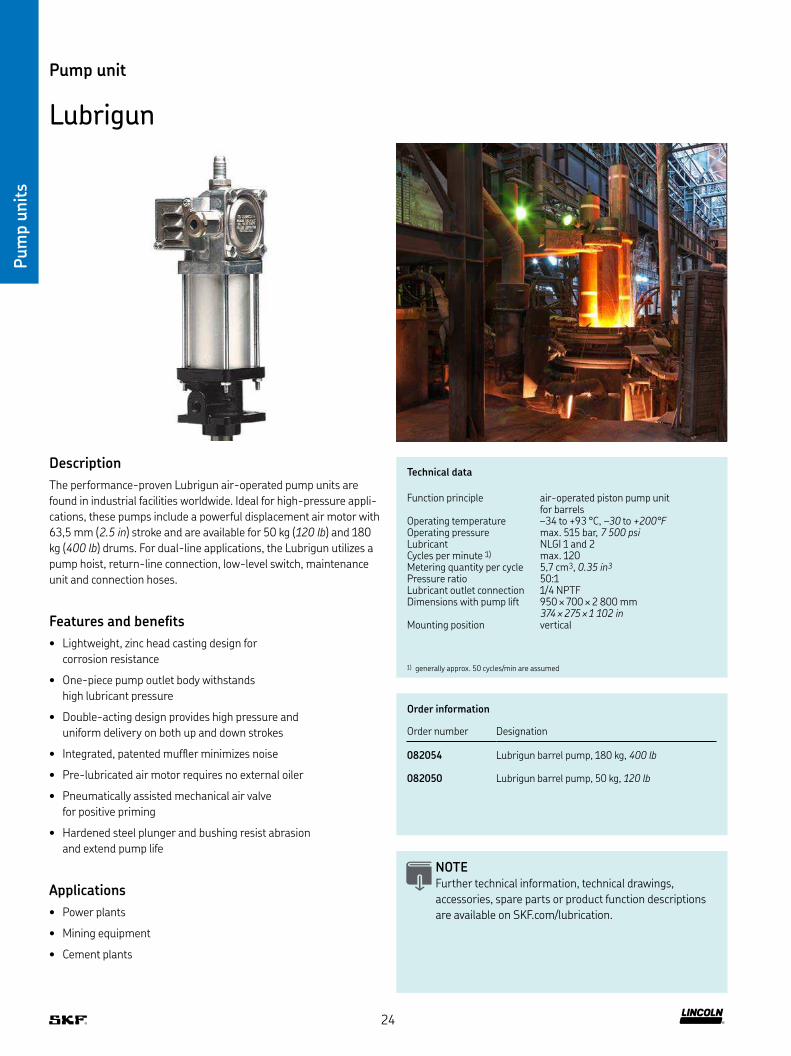
Lubrigun
Description
The performance-proven Lubrigun air-operated pump units are
found in industrial facilities worldwide Ideal for high-pressure appli-
cations, these pumps include a powerful displacement air motor with
63,5 mm (2.5 in) stroke and are available for 50 kg (120 lb) and 180
kg (400 lb) drums For dual-line applications, the Lubrigun utilizes a
pump hoist, return-line connection, low-level switch, maintenance
unit and connection hoses
Features and beneits
• Lightweight, zinc head casting design for
corrosion resistance
• One-piece pump outlet body withstands
high lubricant pressure
• Double-acting design provides high pressure and
uniform delivery on both up and down strokes
• Integrated, patented mufler minimizes noise
• Pre-lubricated air motor requires no external oiler
• Pneumatically assisted mechanical air valve
for positive priming
• Hardened steel plunger and bushing resist abrasion
and extend pump life
Applications
• Power plants
• Mining equipment
• Cement plants
NOTE Further technical information, technical drawings,
accessories, spare parts or product function descriptions
are available on SKF com/lubrication
1) generally approx 50 cycles/min are assumed
Order information
Order number Designation
082054 Lubrigun barrel pump, 180 kg, 400 lb
082050 Lubrigun barrel pump, 50 kg, 120 lb
24
Pum
p u
nit
s
Accessories
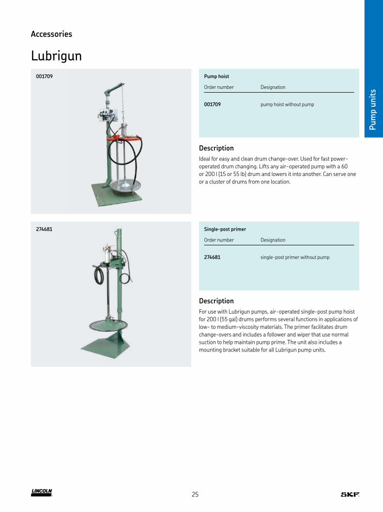
Lubrigun
Pump hoist
Order number Designation
001709 pump hoist without pump
Description
Ideal for easy and clean drum change-over Used for fast power-
operated drum changing Lifts any air-operated pump with a 60
or 200 l (15 or 55 lb) drum and lowers it into another Can serve one
or a cluster of drums from one location
Single-post primer
Order number Designation
274681 single-post primer without pump
Description
For use with Lubrigun pumps, air-operated single-post pump hoist
for 200 l (55 gal) drums performs several functions in applications of
low- to medium-viscosity materials The primer facilitates drum
change-overs and includes a follower and wiper that use normal
suction to help maintain pump prime The unit also includes a
mounting bracket suitable for all Lubrigun pump units
001709
274681
25
Pum
p u
nit
s
Technical data
Function principle air-operated piston pump unit for barrels
Operating temperature –34 to +93 °C, –30 to +200 °FOperating pressure max 500 bar, 7 300 psiLubricant NLGI 1 and 2Cycles per minute max 70Metering quantity per cycle 34–60,5 cm3, 2.1–3.7 in3
Pressure ratio 50:1, 75:1 (recommended for lubrication systems)
Lubricant outlet connection 3/4 NPTF
Dimensions 950 × 700 × 2 800 mm 374 × 275 × 1 103 in
Mounting position vertical
Pump unit
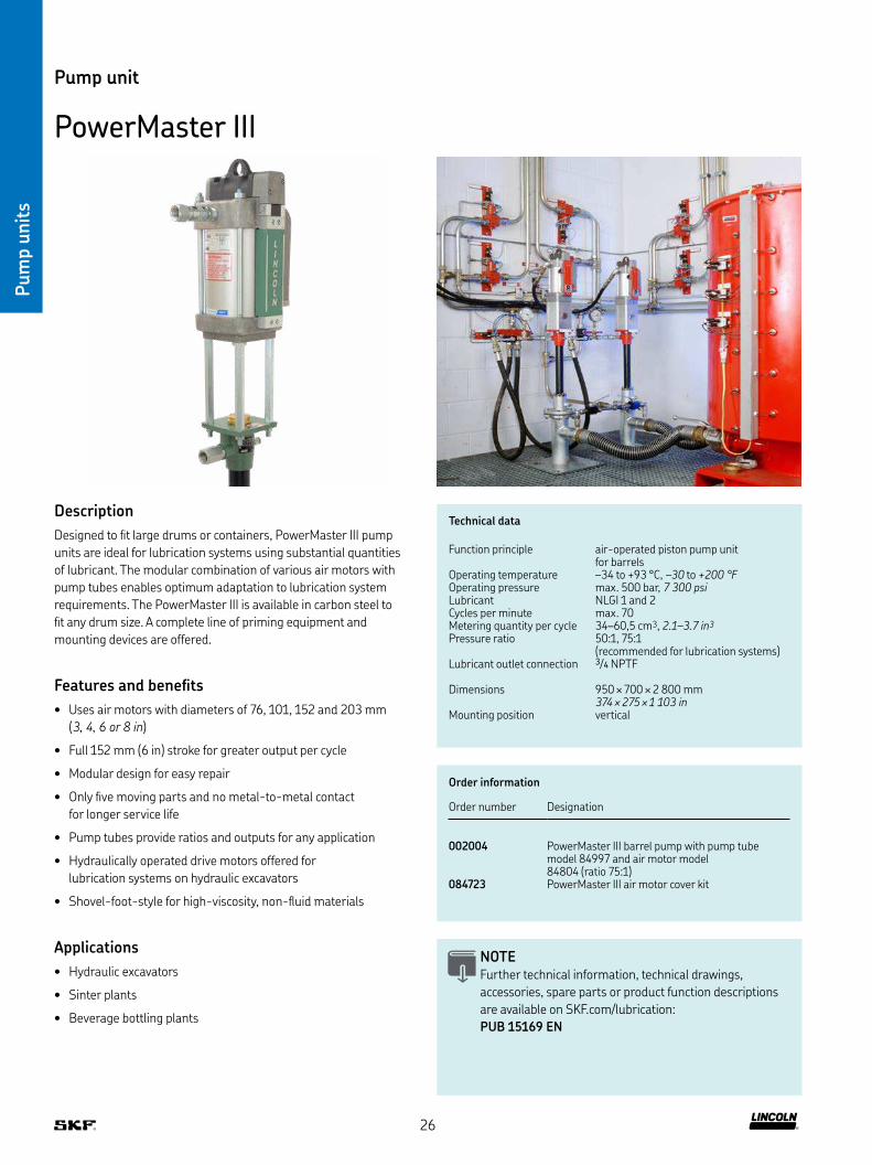
PowerMaster III
Description
Designed to it large drums or containers, PowerMaster III pump
units are ideal for lubrication systems using substantial quantities
of lubricant The modular combination of various air motors with
pump tubes enables optimum adaptation to lubrication system
requirements The PowerMaster III is available in carbon steel to
it any drum size A complete line of priming equipment and
mounting devices are offered
Features and beneits
• Uses air motors with diameters of 76, 101, 152 and 203 mm
(3, 4, 6 or 8 in)
• Full 152 mm (6 in) stroke for greater output per cycle
• Modular design for easy repair
• Only ive moving parts and no metal-to-metal contact
for longer service life
• Pump tubes provide ratios and outputs for any application
• Hydraulically operated drive motors offered for
lubrication systems on hydraulic excavators
• Shovel-foot-style for high-viscosity, non-luid materials
Applications
• Hydraulic excavators
• Sinter plants
• Beverage bottling plants
NOTE Further technical information, technical drawings,
accessories, spare parts or product function descriptions
are available on SKF com/lubrication:
PUB 15169 EN
Order information
Order number Designation
002004 PowerMaster III barrel pump with pump tube model 84997 and air motor model 84804 (ratio 75:1)
084723 PowerMaster III air motor cover kit
26

Pum
p u
nit
s
Accessories
PowerMaster III
Pump hoist
Order number Designation
001709 single-post primer elevator
Description
This single-post elevator is ideal for quick and easy power-operated
drum changes Lifts any air-operated pump from 60 and 200 l,
15 or 55 lb drum and lowers it into another Can serve one or a
cluster of drums from one location
Single post primer
Order number Designation
002716 single-post primer
Description
For use with PowerMaster III Series 2000 pumps, this
air-operated, single-post pump hoist for 200 l (55 gal) drums
performs several functions in applications of low- to medi-
um-viscosity materials The primer facilitates drum change-
overs and includes a follower and wiper that use normal suc-
tion to help maintain pump prime The unit also includes a
mounting bracket for all PowerMaster III pumps
Air motor cover panel kit
Order number Designation
84723 series III air motor cover panel kit
Description
Metal cover its tie rods and encloses the moving plunger rod
001709
002716
84723
27
Met
erin
g d
evic
es
28

Block design metering devices
Product Material housing and design Operation pressure max
Outlets Metered quantity per stroke Page
steel galvanized or stainless steel bar psi cm3 in3
VSKH-KR with indicator pin, adjustable output 400 5 800 1–8 0–1,5 0–0.09 30VSKH–KRFKM with FKM seals 400 5 800 1–8 0–1,5 0–0.09 30VSKV–KR with indicator pin, adjustable output 400 5 800 1–8 0–1,5 0–0.09 30VSKV–KRFKM with FKM seals 400 5 800 1–8 0–1,5 0–0.09 30
VSG–KR with indicator pin, adjustable output 400 5 800 1–8 0–2,2 0–0.13 34VSG–KRFKM with FKM seals 400 5 800 1–8 0–2,2 0–0.13 34VSG–KR–NP with piston detector 400 5 800 1–8 0–2,2 0–0.13 34VSG–KR–KA with adapter for limit switch 400 5 800 2, 4, 6, 8 0–2,2 0–0.13 34VSG–KR–KS with limit switch 400 5 800 1–8 0–2,2 0–0.13 34VSG–KR–KD, D with ixed metering screw 400 5 800 1–8 0,55; 1,1; 1,65; 2,2 0.04, 0.07, 0.1, 0.13 34
VSL–KR with indicator pin, adjustable output 400 5 800 1–8 0–5 0–0.3 38VSL–KR-FKM with FKM seals 400 5 800 1–8 0–5 0–0.3 38VSL–KR–NP with piston detector 400 5 800 1–8 0–5 0–0.3 38VSL–KR–KA with adapter for limit switch 400 5 800 2, 4, 6, 8 0–5 0–0.3 38VSL–KR–KS with limit switch 400 5 800 1–8 0–5 0–0.3 38VSL–KR–KD, D with ixed metering screw 400 5 800 1–8 1,25; 2,5; 3,75; 5 0.07, 0.15, 0.23, 0.3 38
Overview of metering devices
Modular design metering devices
Product Material housing and design Operation pressure max
Outlets 1) Metered quantity per stroke Page
steel galvanized or stainless steel bar psi cm3 in3
SGA with indicator pin, adjustable output 250 3 600 1–12 0,17-4,85 0.01-0.29 42
SG with indicator pin, adjustable output 250 3 600 1–12 4,88-98 0.29-5.98 42
Met
erin
g d
evic
es
1) Metering device outlets 1 or 2, metering device groups up to 12 outlets (on top of base plate BPSG)
29
Met
erin
g d
evic
es
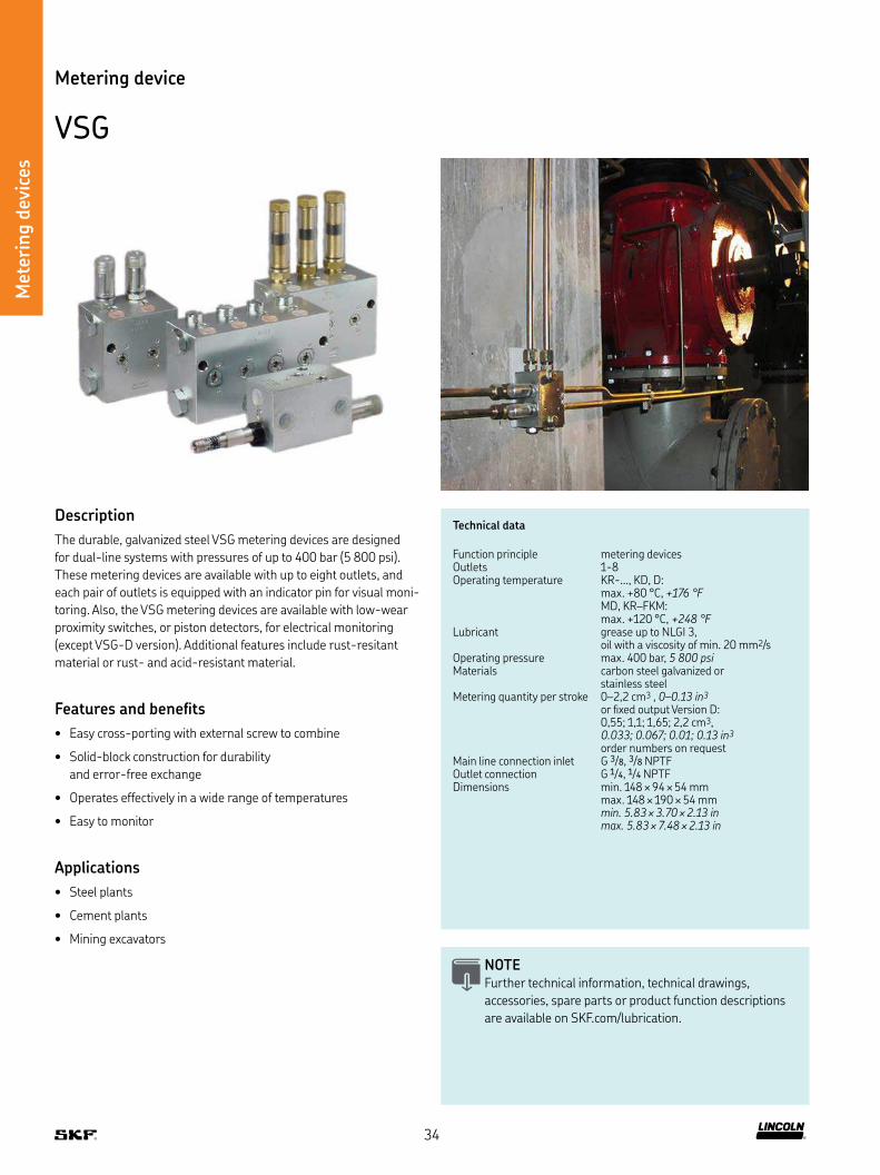
Technical data
Function principle metering devices Outlets 1-8Operating temperature KR:
max +80 °C, +176 °F MD, KR–FKM: max +120 °C, +248 °F
Operating pressure max 400 bar, 5 800 psiLubricant grease up to NLGI 3,
oil with a viscosity of min 20 mm2/sMaterials carbon steel galvanized or
stainless steelMetering quantity per stroke 0–1,5 cm3, 0–0.09 in3
orixed output Version D: 0,3; 0,6; 1,2; 1,5 cm3
0.018; 0.037; 0.073; 0.092 in3
order numbers on request Main line connection inlet G 1/4Outlet connection G 1/4Dimensions depending on the model:
min 124 × 52 × 57 mm max 124 × 136 × 57 mmmin. 4.88 × 2.05 × 2.24 in max. 4.88 × 5.35 × 2.24 in
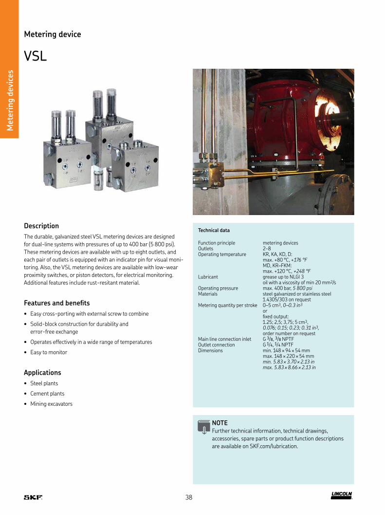
Metering device
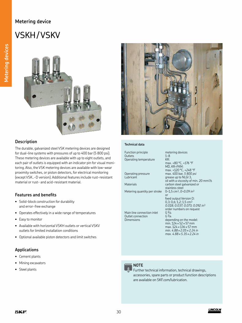
VSKH / VSKV
Description
The durable, galvanized steel VSK metering devices are designed
for dual-line systems with pressures of up to 400 bar (5 800 psi)
These metering devices are available with up to eight outlets, and
each pair of outlets is equipped with an indicator pin for visual moni-
toring Also, the VSK metering devices are available with low-wear
proximity switches, or piston detectors, for electrical monitoring
(except VSK -D version) Additional features include rust-resistant
material or rust- and acid-resistant material
Features and beneits
• Solid-block construction for durability
and error-free exchange
• Operates effectively in a wide range of temperatures
• Easy to monitor
• Available with horizontal VSKH outlets or vertical VSKV
outlets for limited installation conditions
• Optional available piston detectors and limit switches
Applications
• Cement plants
• Mining excavators
• Steel plantsNOTE Further technical information, technical drawings,
accessories, spare parts or product function descriptions
are available on SKF com/lubrication
30

Met
erin
g d
evic
es
Metering device
VSKH / VSKV
VSKH and VSKV, with connection thread BSPP
Order number Outlets Material Indicator pin adjustable output 0–1,5 cm3 (0–0.09 in3)
Steel Stainless steel Stainless steelVSKH–KR VSKV–KR galvanized 1 4305 / 303 1 4571 / 316 Ti KR FKM U-cup seal
620-27438-1 620-27442-1 1 • – – • –620-27418-1 620-27422-1 2 • – – • –620-27439-1 620-27443-1 3 • – – • –620-27419-1 620-27423-1 4 • – – • –620-27440-1 620-27444-1 5 • – – • –620-27420-1 620-27424-1 6 • – – • –620-27441-1 620-27445-1 7 • – – • –620-27421-1 620-27425-1 8 • – – • –
620-27488-1 620-27496-1 1 – • – • –620-27489-1 620-27497-1 2 – • – • –620-27490-1 620-27498-1 3 – • – • –620-27491-1 620-27499-1 4 – • – • –620-27492-1 620-27500-1 5 – • – • –620-27493-1 620-27501-1 6 – • – • –620-27494-1 620-27502-1 7 – • – • –620-27495-1 620-27503-1 8 – • – • –
620-27766-1 620-27857-1 1 – – • • –620-27767–1 620-27858-1 2 – – • • –620-27768-1 620-27859-1 3 – – • • –620-27769-1 620-27860-1 4 – – • • –620-27770-1 620-27861-1 5 – – • • –620-27771-1 620-27862-1 6 – – • • –620-27772-1 620-27863-1 7 – – • • –620-27773-1 620-27864-1 8 – – • • –
620-28409-1 620-28413-1 1 • – – • •620-28376-1 620-28392-1 2 • – – • •620-28410-1 620-28414-1 3 • – – • •620-28366-1 620-28393-1 4 • – – • •620-28411-1 620-28415-1 5 • – – • •620-28367-1 620-28374-1 6 • – – • •620-28412-1 620-28416-1 7 • – – • •620-28391-1 620-28394-1 8 • – – • •
VSKH–MD , with connection thread BSPP
Order number Outlets Material Metering quantity max
Metering device Regulating sleeve Protection cap cm3 in3
620-41086-1 2 steel, galvanized brass brass 1,50 0.09620-41122-1 2 steel, galvanized brass plastic 1,50 0.09620-41086-5 3 steel, galvanized brass brass 1,50 0.09620-41086-2 4 steel, galvanized brass brass 1,50 0.09620-41122-2 4 steel, galvanized brass plastic 1,50 0.09620-41086-6 5 steel, galvanized brass brass 1,50 0.09620-41086-3 6 steel, galvanized brass brass 1,50 0.09620-41122-3 6 steel, galvanized brass plastic 1,50 0.09620-41086-7 7 steel, galvanized brass brass 1,50 0.09620-41086-4 8 steel, galvanized brass brass 1,50 0.09620-41122-4 8 steel, galvanized brass plastic 1,50 0.09
31
Met
erin
g d
evic
es VSKV–MD , with connection thread BSPP
Order number Outlets Material Metering quantity max
Metering device Regulating sleeve Protection cap cm3 in3
620-41123-2 2 steel, galvanized brass plastic 1,50 0.09620-41089-2 2 steel, galvanized brass brass 1,50 0.09620-41123-4 4 steel, galvanized brass plastic 1,50 0.09620-41089-4 4 steel, galvanized brass brass 1,50 0.09620-41123-6 6 steel, galvanized brass plastic 1,50 0.09620-41089-6 6 steel, galvanized brass brass 1,50 0.09620-41123-8 8 steel, galvanized brass plastic 1,50 0.09620-41089-8 8 steel, galvanized brass brass 1,50 0.09
Metering device
VSKH / VSKV
Accessories
Metering screw for VSKH/VSKV
Order number Output Material
cm3 in3
303-19351-1 0,30 0.018 Steel303-19352-1 0,60 0.037 Steel303-19354-1 1,20 0.073 Steel303-19375-1 1,50 0.091 Steel
303-19356-1 0,30 0.018 Stainless steel 1 4571/316 Ti303-19357-1 0,60 0.037 Stainless steel 1 4571/316 Ti303-19359-1 1,20 0.073 Stainless steel 1 4571/316 Ti303-19374-1 1,50 0.091 Stainless steel 1 4571/316 Ti
Extensions for VSK, VSG and VSL
Order number Model
420-23628-1 VSKH420-23790-1 VSKH, 1 4305
32

Met
erin
g d
evic
es
Accessories
VSKH / VSKV
Magnetic indicator for VSKH/VSKV
Order number Output setting Protection cap material
cm3 in3
520-33109-1 0,30 0.018 Brass520-33110-1 0,60 0.037 Brass520-33112-1 1,20 0.073 Brass520-33075-1 1,50 0.091 Brass
520-33266-1 0,30 0.018 Plastic520-33267-1 0,60 0.037 Plastic520-33268-1 1,20 0.073 Plastic520-33269-1 1,50 0.091 Plastic
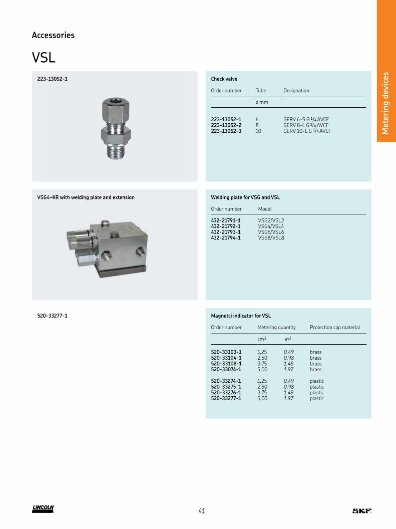
VSG4–KR with welding plate and extension
223-13052-1
Welding plates for VSK, VSG and VSL
Order number Model
432-23698-1 VSK2432-23699-1 VSK4432-23700-1 VSK6432-23701-1 VSK8432-21791-1 VSG2/VSL2432-21792-1 VSG4/VSL4432-21793-1 VSG6/VSL6432-21794-1 VSG8/VSL8
520-33075-1
Check valve
Order number Tube Designation
ø mm
223-13052-1 6 GERV 6-S G 1/4 AVCF223-13052-2 8 GERV 8-L G 1/4 AVCF223-13052-3 10 GERV 10-L G 1/4 AVCF
33
Met
erin
g d
evic
es
Technical data
Function principle metering devices Outlets 1-8Operating temperature KR- , KD, D:
max +80 °C, +176 °F MD, KR–FKM: max +120 °C, +248 °F
Lubricant grease up to NLGI 3,oil with a viscosity of min 20 mm2/s
Operating pressure max 400 bar, 5 800 psiMaterials carbon steel galvanized or
stainless steelMetering quantity per stroke 0–2,2 cm3 , 0–0.13 in3
or ixed output Version D: 0,55; 1,1; 1,65; 2,2 cm3, 0.033; 0.067; 0.01; 0.13 in3 order numbers on request
Main line connection inlet G 3/8, 3/8 NPTFOutlet connection G 1/4, 1/4 NPTFDimensions min 148 × 94 × 54 mm
max 148 × 190 × 54 mmmin. 5.83 × 3.70 × 2.13 in max. 5.83 × 7.48 × 2.13 in
Metering device
VSG
Description
The durable, galvanized steel VSG metering devices are designed
for dual-line systems with pressures of up to 400 bar (5 800 psi)
These metering devices are available with up to eight outlets, and
each pair of outlets is equipped with an indicator pin for visual moni-
toring Also, the VSG metering devices are available with low-wear
proximity switches, or piston detectors, for electrical monitoring
(except VSG-D version) Additional features include rust-resitant
material or rust- and acid-resistant material
Features and beneits
• Easy cross-porting with external screw to combine
• Solid-block construction for durability
and error-free exchange
• Operates effectively in a wide range of temperatures
• Easy to monitor
Applications
• Steel plants
• Cement plants
• Mining excavators
NOTE Further technical information, technical drawings,
accessories, spare parts or product function descriptions
are available on SKF com/lubrication
34
Met
erin
g d
evic
es
Metering device
VSG
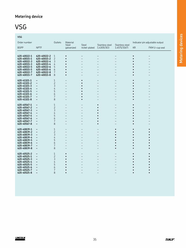
VSG
Order number Outlets Material Indicator pin adjustable output BSPP
NPTF
Steel galvanized
Steel nickel-plated
Stainless steel 1 4305/303
Stainless steel 1 4571/316Ti
KR
FKM U-cup seal
620-40022-1 620-40022-2 1 • – – – • –620-40015-1 620-40015-2 2 • – – – • –620-40022-3 620-40022-4 3 • – – – • –620-40015-3 620-40015-4 4 • – – – • –620-40022-5 620-40022-6 5 • – – – • –620-40015-5 620-40015-6 6 • – – – • –620-40022-7 620-40022-8 7 • – – – • –620-40015-7 620-40015-8 8 • – – – • –
620-41321-1 – 1 – • – – • –620-41321-2 – 2 – • – – • –620-41321-3 – 3 – • – – • –620-41321-4 – 4 – • – – • –620-41321-5 – 5 – • – – • –620-41321-6 – 6 – • – – • –620-41321-7 – 7 – • – – • –620-41321-8 – 8 – • – – • –
620-40567-1 – 1 – – • – • –620-40567-2 – 2 – – • – • –620-40567-3 – 3 – – • – • –620-40567-4 – 4 – – • – • –620-40567-5 – 5 – – • – • –620-40567-6 – 6 – – • – • –620-40567-7 – 7 – – • – • –620-40567-8 – 8 – – • – • –
620-40839-1 – 1 – – – • • •620-40839-2 – 2 – – – • • •620-40839-3 – 3 – – – • • •620-40839-4 – 4 – – – • • •620-40839-5 – 5 – – – • • •620-40839-6 – 6 – – – • • •620-40839-7 – 7 – – – • • •620-40839-8 – 8 – – – • • •
620-40525-2 – 1 • – – – • •620-40525-1 – 2 • – – – • •620-40525-3 – 3 • – – – • •620-40525-4 – 4 • – – – • •620-40525-5 – 5 • – – – • •620-40525-6 – 6 • – – – • •620-40525-7 – 7 • – – – • •620-40525-8 – 8 • – – – • •
35
Met
erin
g d
evic
es
Metering device
VSG
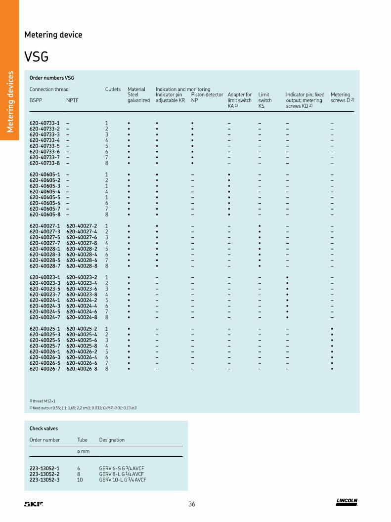
Order numbers VSG
Connection thread Outlets Material Indication and monitoring BSPP
NPTF
Steel galvanized
Indicator pin adjustable KR
Piston detector NP
Adapter for limit switch KA 1)
Limit switch KS
Indicator pin; ixed output; metering screws KD 2)
Metering screws D 2)
620-40733-1 – 1 • • • – – – –620-40733-2 – 2 • • • – – – –620-40733-3 – 3 • • • – – – –620-40733-4 – 4 • • • – – – –620-40733-5 – 5 • • • – – – –620-40733-6 – 6 • • • – – – –620-40733-7 – 7 • • • – – – –620-40733-8 – 8 • • • – – – –
620-40605-1 – 1 • • – • – – –620-40605-2 – 2 • • – • – – –620-40605-3 – 1 • • – • – – –620-40605-4 – 4 • • – • – – –620-40605-5 – 1 • • – • – – –620-40605-6 – 6 • • – • – – –620-40605-7 – 7 • • – • – – –620-40605-8 – 8 • • – • – – –
620-40027-1 620-40027-2 1 • • – – • – –620-40027-3 620-40027-4 2 • • – – • – –620-40027-5 620-40027-6 3 • • – – • – –620-40027-7 620-40027-8 4 • • – – • – –620-40028-1 620-40028-2 5 • • – – • – –620-40028-3 620-40028-4 6 • • – – • – –620-40028-5 620-40028-6 7 • • – – • – –620-40028-7 620-40028-8 8 • • – – • – –
620-40023-1 620-40023-2 1 • – – – – • –620-40023-3 620-40023-4 2 • – – – – • –620-40023-5 620-40023-6 3 • – – – – • –620-40023-7 620-40023-8 4 • – – – – • –620-40024-1 620-40024-2 5 • – – – – • –620-40024-3 620-40024-4 6 • – – – – • –620-40024-5 620-40024-6 7 • – – – – • –620-40024-7 620-40024-8 8 • – – – – • –
620-40025-1 620-40025-2 1 • – – – – – •620-40025-3 620-40025-4 2 • – – – – – •620-40025-5 620-40025-6 3 • – – – – – •620-40025-7 620-40025-8 4 • – – – – – •620-40026-1 620-40026-2 5 • – – – – – •620-40026-3 620-40026-4 6 • – – – – – •620-40026-5 620-40026-6 7 • – – – – – •620-40026-7 620-40026-8 8 • – – – – – •
1) thread M12×1
2) fixed output 0,55; 1,1; 1,65; 2,2 cm3; 0.033; 0.067; 0.01; 0.13 in3
Check valves
Order number Tube Designation
ø mm
223-13052-1 6 GERV 6-S G 1/4 AVCF223-13052-2 8 GERV 8-L G 1/4 AVCF223-13052-3 10 GERV 10-L G 1/4 AVCF
36
Met
erin
g d
evic
es
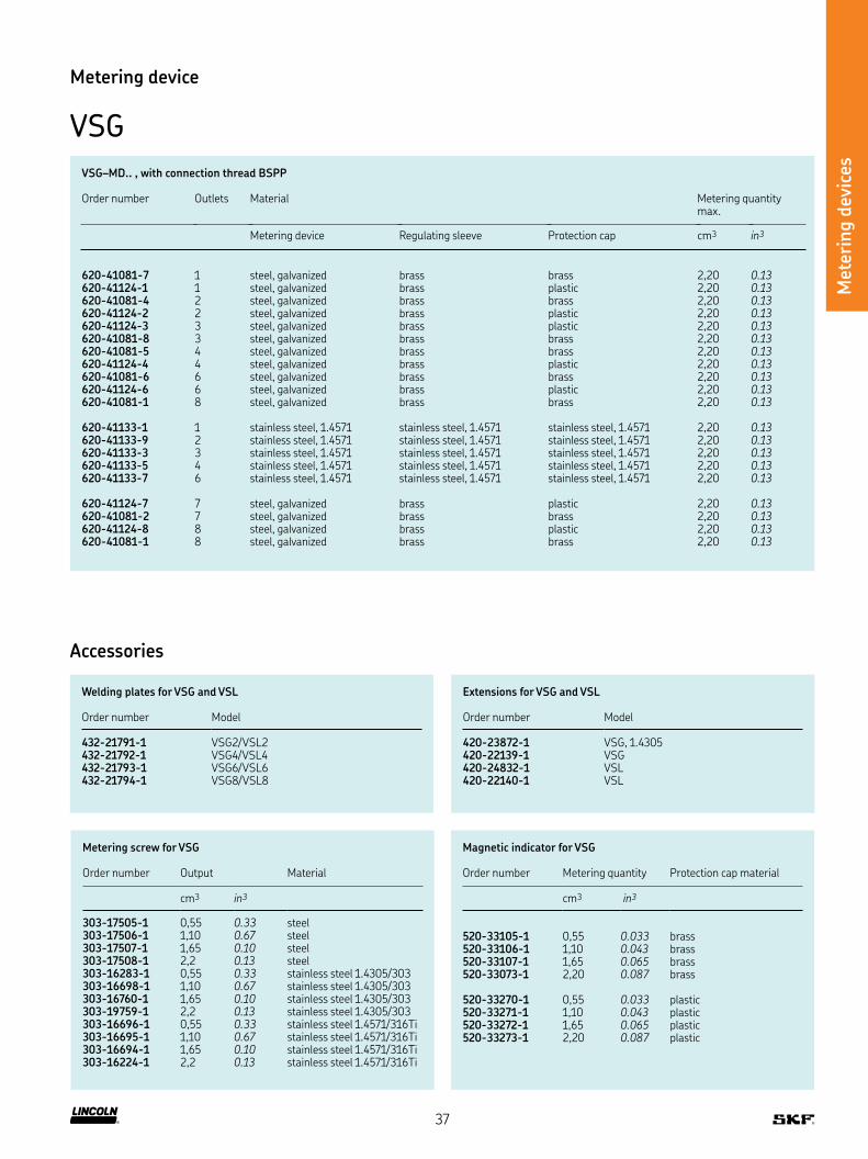
Metering device
VSG
Metering screw for VSG
Order number Output Material
cm3 in3
303-17505-1 0,55 0.33 steel303-17506-1 1,10 0.67 steel303-17507-1 1,65 0.10 steel303-17508-1 2,2 0.13 steel303-16283-1 0,55 0.33 stainless steel 1 4305/303303-16698-1 1,10 0.67 stainless steel 1 4305/303303-16760-1 1,65 0.10 stainless steel 1 4305/303303-19759-1 2,2 0.13 stainless steel 1 4305/303303-16696-1 0,55 0.33 stainless steel 1 4571/316Ti303-16695-1 1,10 0.67 stainless steel 1 4571/316Ti303-16694-1 1,65 0.10 stainless steel 1 4571/316Ti303-16224-1 2,2 0.13 stainless steel 1 4571/316Ti
Extensions for VSG and VSL
Order number Model
420-23872-1 VSG, 1 4305420-22139-1 VSG420-24832-1 VSL420-22140-1 VSL
Welding plates for VSG and VSL
Order number Model
432-21791-1 VSG2/VSL2432-21792-1 VSG4/VSL4432-21793-1 VSG6/VSL6432-21794-1 VSG8/VSL8
Magnetic indicator for VSG
Order number Metering quantity Protection cap material
cm3 in3
520-33105-1 0,55 0.033 brass520-33106-1 1,10 0.043 brass520-33107-1 1,65 0.065 brass520-33073-1 2,20 0.087 brass
520-33270-1 0,55 0.033 plastic520-33271-1 1,10 0.043 plastic520-33272-1 1,65 0.065 plastic520-33273-1 2,20 0.087 plastic
VSG–MD , with connection thread BSPP
Order number Outlets Material Metering quantity max
Metering device Regulating sleeve Protection cap cm3 in3
620-41081-7 1 steel, galvanized brass brass 2,20 0.13620-41124-1 1 steel, galvanized brass plastic 2,20 0.13620-41081-4 2 steel, galvanized brass brass 2,20 0.13620-41124-2 2 steel, galvanized brass plastic 2,20 0.13620-41124-3 3 steel, galvanized brass plastic 2,20 0.13620-41081-8 3 steel, galvanized brass brass 2,20 0.13620-41081-5 4 steel, galvanized brass brass 2,20 0.13620-41124-4 4 steel, galvanized brass plastic 2,20 0.13620-41081-6 6 steel, galvanized brass brass 2,20 0.13620-41124-6 6 steel, galvanized brass plastic 2,20 0.13620-41081-1 8 steel, galvanized brass brass 2,20 0.13
620-41133-1 1 stainless steel, 1 4571 stainless steel, 1 4571 stainless steel, 1 4571 2,20 0.13620-41133-9 2 stainless steel, 1 4571 stainless steel, 1 4571 stainless steel, 1 4571 2,20 0.13620-41133-3 3 stainless steel, 1 4571 stainless steel, 1 4571 stainless steel, 1 4571 2,20 0.13620-41133-5 4 stainless steel, 1 4571 stainless steel, 1 4571 stainless steel, 1 4571 2,20 0.13620-41133-7 6 stainless steel, 1 4571 stainless steel, 1 4571 stainless steel, 1 4571 2,20 0.13
620-41124-7 7 steel, galvanized brass plastic 2,20 0.13620-41081-2 7 steel, galvanized brass brass 2,20 0.13620-41124-8 8 steel, galvanized brass plastic 2,20 0.13620-41081-1 8 steel, galvanized brass brass 2,20 0.13
Accessories
37
Met
erin
g d
evic
es
Technical data
Function principle metering devices Outlets 2-8Operating temperature KR, KA, KD, D:
max +80 °C, +176 °F MD, KR–FKM: max +120 °C, +248 °F
Lubricant grease up to NLGI 3 oil with a viscosity of min 20 mm2/s
Operating pressure max 400 bar, 5 800 psiMaterials steel galvanized or stainless steel
1 4305/303 on requestMetering quantity per stroke 0–5 cm3, 0–0.3 in3
orixed output: 1 25; 2,5; 3,75; 5 cm3, 0.076; 0.15; 0.23; 0.31 in3, order number on request
Main line connection inlet G 3/8, 3/8 NPTFOutlet connection G 1/4, 1/4 NPTFDimensions min 148 × 94 × 54 mm
max 148 × 220 × 54 mmmin. 5.83 × 3.70 × 2.13 in max. 5.83 × 8.66 × 2.13 in
Metering device
VSL
Description
The durable, galvanized steel VSL metering devices are designed
for dual-line systems with pressures of up to 400 bar (5 800 psi)
These metering devices are available with up to eight outlets, and
each pair of outlets is equipped with an indicator pin for visual moni-
toring Also, the VSL metering devices are available with low-wear
proximity switches, or piston detectors, for electrical monitoring
Additional features include rust-resitant material
Features and beneits
• Easy cross-porting with external screw to combine
• Solid-block construction for durability and
error-free exchange
• Operates effectively in a wide range of temperatures
• Easy to monitor
Applications
• Steel plants
• Cement plants
• Mining excavators
NOTE Further technical information, technical drawings,
accessories, spare parts or product function descriptions
are available on SKF com/lubrication
38

Met
erin
g d
evic
es
Metering device
VSL
VSL carbon steel galvanized
Order number Outlets Material Indication and monitoringBSPP NPTF Steel
galvanizedIndicator pin adjustable output Piston detector
NP Adapter for limit switch KA 1)
Limit switch KSKR FKM U-cup seal
620-40062-1 620-40062-2 1 • • – – – –620-40062-3 620-40062-4 2 • • – – – –620-40062-5 620-40062-6 3 • • – – – –620-40062-7 620-40062-8 4 • • – – – –620-40064-1 610-40064-2 5 • • – – – –620-40064-3 620-40064-4 6 • • – – – –620-40064-5 620-40064-6 7 • • – – – –620-40064-7 620-40064-8 8 • • – – – –
620-40527-1 – 1 • • • – – –620-40526-1 620-40937-2 2 • • • – – –620-40526-9 – 3 • • • – – –620-40526-4 620-40937-4 4 • • • – – –620-40526-5 – 5 • • • – – –620-40526-6 620-40937-6 6 • • • – – –620-40526-7 – 7 • • • – – –620-40526-8 620-40937-8 8 • • • – – –
620-40853-1 – 1 • • – • – –620-40853-2 – 2 • • – • – –620-40853-3 – 3 • • – • – –620-40853-4 – 4 • • – • – –620-40853-6 – 6 • • – • – –620-40853-8 – 8 • • – • – –
620-40637-2 – 2 • • – – • –620-40637-4 – 4 • • – – • –620-40637-6 – 6 • • – • –620-40637-8 – 8 • • – – • –
620-40068-1 620-40068-2 1 • • – – – •620-40068-3 620-40068-4 2 • • – – – •620-40068-5 620-40068-6 3 • • – – – •620-40068-7 620-40068-8 4 • • – – – •620-40069-1 620-40069-2 5 • • – – – •620-40069-3 620-40069-4 6 • • – – – •620-40069-5 620-40069-6 7 • • – – – •620-40069-7 620-40069-8 8 • • – – – •
1) thread M12x1
VSL
Order number Outlets Material Indication and monitoringBSPP
NPTF
Carbon steel galvanized Indicator pin; ixed output; metering screw KD 1)
Metering screw D 1)
620-40065-1 620-40065-2 1 • • –620-40065-3 620-40065-4 2 • • –620-40065-5 620-40065-6 3 • • –620-40065-7 620-40066-8 4 • • –620-40066-1 620-40066-2 5 • • –620-40066-3 620-40066-4 6 • • –620-40066-5 620-40066-6 7 • • –620-40066-7 620-40066-8 8 • • –
620-40063-1 620-40063-2 1 • – •620-40063-3 620-40063-4 2 • – •620-40063-5 620-40063-6 3 • – •620-40063-7 620-40063-8 4 • – •620-40067-1 620-40067-2 5 • – •620-40067-3 620-40067-4 6 • – •620-40067-5 620-40067-6 7 • – •620-40067-7 620-40067-8 8 • – •
1) also available: 1,25; 2,5; 3,75 cm3, 0.07, 0.15, 0.228 in3
39

Met
erin
g d
evic
es
Metering device
VSL
VSL–MD , with connection thread BSPP
Order number Outlets Material Metering quantity max
Metering device Regulating sleeve Protection cap cm3 in3
620-41125-1 1 steel, galvanized brass plastic 5,00 0.30620-41079-6 1 steel, galvanized brass brass 5,00 0.30
620-41079-2 2 steel, galvanized brass brass 5,00 0.30620-41125-2 2 steel, galvanized brass plastic 5,00 0.30
620-41125-3 3 steel, galvanized brass plastic 5,00 0.30620-41079-7 3 steel, galvanized brass brass 5,00 0.30
620-41079-4 4 steel, galvanized brass brass 5,00 0.30620-41125-4 4 steel, galvanized brass plastic 5,00 0.30
620-41125-5 5 steel, galvanized brass plastic 5,00 0.30620-41079-8 5 steel, galvanized brass brass 5,00 0.30
620-41079-5 6 steel, galvanized brass brass 5,00 0.30620-41125-6 6 steel, galvanized brass plastic 5,00 0.30
620-41125-7 7 steel, galvanized brass plastic 5,00 0.30620-41079-9 7 steel, galvanized brass brass 5,00 0.30
620-41079-3 8 steel, galvanized brass brass 5,00 0.30620-41125-8 8 steel, galvanized brass plastic 5,00 0.30
Metering screw for VSL
Order number Metering quantity Material
cm3 in3
303-17509-1 1,25 0.49 steel303-17510-1 2,50 0.98 steel303-17511-1 3,75 1.48 steel303-17512-1 5,00 1.97 steel
303-16106-1 2,50 0.98 stainless steel 1 4305/303303-19809-1 3,75 1.48 stainless steel 1 4305/303303-19760-1 5,00 1.97 stainless steel 1 4305/303
Extensions for VSL
Order number Model
420-24832-1 VSL420-22140-1 VSL
40
Met
erin
g d
evic
es
Accessories
VSL
Magnetci indicator for VSL
Order number Metering quantity Protection cap material
cm3 in3
520-33103-1 1,25 0.49 brass520-33104-1 2,50 0.98 brass520-33108-1 3,75 1.48 brass520-33074-1 5,00 1.97 brass
520-33274-1 1,25 0.49 plastic520-33275-1 2,50 0.98 plastic520-33276-1 3,75 1.48 plastic520-33277-1 5,00 1.97 plastic
520-33277-1
Welding plate for VSG and VSL
Order number Model
432-21791-1 VSG2/VSL2432-21792-1 VSG4/VSL4432-21793-1 VSG6/VSL6432-21794-1 VSG8/VSL8
Check valve
Order number Tube Designation
ø mm
223-13052-1 6 GERV 6-S G 1/4 AVCF223-13052-2 8 GERV 8-L G 1/4 AVCF223-13052-3 10 GERV 10-L G 1/4 AVCF
VSG4–KR with welding plate and extension
223-13052-1
41
Met
erin
g d
evic
es
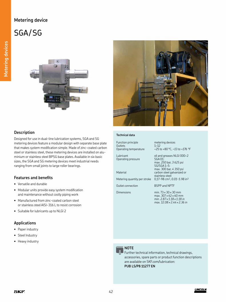
Technical data
Function principle metering devicesOutlets 1–12Operating temperature –25 to +80 °C, –13 to +176 °F
Lubricant oil and greases NLGI 000–2Operating pressure SGA 01:
max 250 bar, 3 625 psiSG/SGA 1–5: max 300 bar, 4 350 psi
Material carbon steel galvanized or stainless steel
Metering quantity per stroke 0,17-98 cm3, 0.01-5.98 in3
Outlet connection BSPP and NPTF
Dimensions min 73 × 30 × 30 mm max 307 × 62 × 60 mmmin. 2.87 × 1.18 × 1.18 in max. 12.08 × 2.44 × 2.36 in
Metering device
SGA / SG
Description
Designed for use in dual-line lubrication systems, SGA and SG
metering devices feature a modular design with separate base plate
that makes system modiication simple Made of zinc-coated carbon
steel or stainless steel, these metering devices are installed on alu-
minium or stainless steel BPSG base plates Available in six basic
sizes, the SGA and SG metering devices meet industrial needs
ranging from small joints to large roller bearings
Features and beneits
• Versatile and durable
• Modular units provide easy system modiication
and maintenance without costly piping work
• Manufactured from zinc-coated carbon steel
or stainless steel AISI-316 L to resist corrosion
• Suitable for lubricants up to NLGI 2
Applications
• Paper industry
• Steel Industry
• Heavy industry
NOTE Further technical information, technical drawings,
accessories, spare parts or product function descriptions
are available on SKF com/lubrication:
PUB LS/P8 11277 EN
42

Met
erin
g d
evic
es
Metering device
SGA / SG
Order information
Order number Designation Output per outlet Outlets Material
cm3/stroke
in3/stroke
Carbon steel galvanized
Stainless steel
Without mechanical indicator
12387460 SGA-011-ZN 0,17–0,79 0.010–0.048 1 • – –12387560 SGA-11-ZN 0,28–1,42 0.017–0.086 1 • – –12387660 SGA-21-ZN 0,80–4,94 0.048–0.301 1 • – –12388110 SG-31-ZN 1) 4,88–31,81 0.297–1.941 1 • – –
12387510 SGA-012-ZN 0,17–0,79 0.010–0.048 2 • – –12387610 SGA-12-ZN 0,28–1,42 0.017–0.086 2 • – –12387710 SGA-22-ZN 0,80–4,94 0.048–0.301 2 • – –12388160 SG-32-ZN 1) 4,88–31,81 0.297–1.941 2 • – –
12386560 SGA-011-SS 0,17–0,79 0.010–0.048 1 – • –12386660 SGA-11-SS 0,28–1,42 0.017–0.086 1 – • –12386760 SGA-21-SS 0,80–4,94 0.048–0.301 1 – • –
12386610 SGA-012-SS 0,17–0,79 0.010–0.048 2 – • –12386710 SGA-12-SS 0,28–1,42 0.017–0.086 2 – • –12386810 SGA-22-SS 0,80–4,94 0.048–0.301 2 – • –
12387160 SG-31-SS 1) 4,88–31,81 0.297–1.941 1 – • –12387260 SG-41-SS 1) 10,96–52,57 0.668–3.208 1 – • –12387360 SG-51-SS 1) 48,03–100,45 2.930–6.129 1 – • –
12387210 SG-32-SS 1) 4,88–31,81 0.297–1.941 2 – • –12387310 SG-42-SS 1) 10,96–52,57 0.668–3.208 2 – • –12387410 SG-52-SS 1) 48,03–100,45 2.930–6.129 2 – • –
12387470 SGA-011-ZN-WI 2) 3) 0,17–0,79 0.010–0.048 1 • – –12387570 SGA-11-ZN-WI 2) 3) 0,28–1,42 0.017–0.086 1 • – –12387670 SGA-21-ZN-WI 2) 3) 0,80–4,94 0.048–0.301 1 • – –
12387520 SGA-012-ZN-WI 2) 3) 0,17–0,79 0.010–0.048 2 • – –12387620 SGA-12-ZN-WI 2) 3) 0,28–1,42 0.017–0.086 2 • – –12387720 SGA-22-ZN-WI 2) 3) 0,80–4,94 0.048–0.301 2 • – –
12387525 SGA-011-ZN-NI 3) 0,17–0,79 0.010–0.048 1 • – •12387625 SGA-11-ZN-NI 3) 0,28–1,42 0.017–0.086 1 • – •12387680 SGA-21-ZN-NI 3) 0,80–4,94 0.048–0.301 1 • – •
12387530 SGA-012-ZN-NI 3) 0,17–0,79 0.010–0.048 2 • – •12387630 SGA-12-ZN-NI 3) 0,28–1,42 0.017–0.086 2 • – •12387685 SGA-22-ZN-NI 3) 0,80–4,94 0.048–0.301 2 • – •
1) That design requires two places on base plate
2) In WI models there is a metal indicator pin on indicator end (pin moves out and in)
3) In both WI and NI models there is included 3 different size of metering screws
43
Met
erin
g d
evic
es
Accessories
SGA / SG
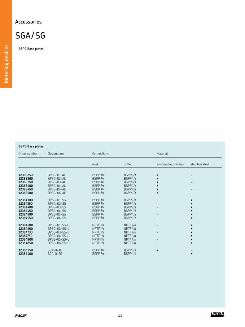
BSPG Base plates
Order number Designation Connections Material
inlet
outlet
anodized aluminium
stainless steel
12383250 BPSG-01-AL BSPP 1/4 BSPP 1/8 • –12383300 BPSG-02-AL BSPP 1/4 BSPP 1/8 • –12383350 BPSG-03-AL BSPP 1/4 BSPP 1/8 • –12383400 BPSG-04-AL BSPP 1/4 BSPP 1/8 • –12383450 BPSG-05-AL BSPP 1/4 BSPP 1/8 • –12383500 BPSG-06-AL BSPP 1/4 BSPP 1/8 • –
12384300 BPSG-01-SS BSPP 1/4 BSPP 1/8 – •12384350 BPSG-02-SS BSPP 1/4 BSPP 1/8 – •12384400 BPSG-03-SS BSPP 1/4 BSPP 1/8 – •12384450 BPSG-04-SS BSPP 1/4 BSPP 1/8 – •12384500 BPSG-05-SS BSPP 1/4 BSPP 1/8 – •12384550 BPSG-06-SS BSPP 1/4 BSPP 1/8 – •
12384600 BPSG-01-SS-U NPTF 1/4 NPTF 1/8 – •12384650 BPSG-02-SS-U NPTF 1/4 NPTF 1/8 – •12384700 BPSG-03-SS-U NPTF 1/4 NPTF 1/8 – •12384750 BPSG-04-SS-U NPTF 1/4 NPTF 1/8 – •12384800 BPSG-05-SS-U NPTF 1/4 NPTF 1/8 – •12384850 BPSG-06-SS-U NPTF 1/4 NPTF 1/8 – •
12386350 SGA-0-AL BSPP 1/4 BSPP 1/8 • –12386400 SGA-0-SS BSPP 1/4 BSPP 1/8 – •
BSPG Base plates
44
Met
erin
g d
evic
es
Accessories
SGA / SG
NOTE Further technical information, technical drawings,
accessories, spare parts or product function descriptions
are available on SKF com/lubrication:
PUB LS/P8 11277 EN
Description
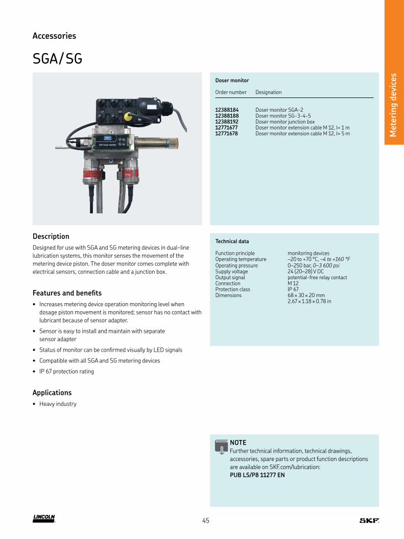
Designed for use with SGA and SG metering devices in dual-line
lubrication systems, this monitor senses the movement of the
metering device piston The doser monitor comes complete with
electrical sensors, connection cable and a junction box
Features and beneits
• Increases metering device operation monitoring level when
dosage piston movement is monitored; sensor has no contact with
lubricant because of sensor adapter
• Sensor is easy to install and maintain with separate
sensor adapter
• Status of monitor can be conirmed visually by LED signals
• Compatible with all SGA and SG metering devices
• IP 67 protection rating
Applications
• Heavy industry
Technical data
Function principle monitoring devicesOperating temperature –20 to +70 °C, –4 to +160 °FOperating pressure 0–250 bar, 0–3 600 psiSupply voltage 24 (20–28) V DCOutput signal potential-free relay contactConnection M 12Protection class IP 67Dimensions 68 × 30 × 20 mm
2 67 × 1 18 × 0 78 in
Doser monitor
Order number Designation
12388184 Doser monitor SGA-212388188 Doser monitor SG-3-4-512388192 Doser monitor junction box12771677 Doser monitor extension cable M 12, l= 1 m12771678 Doser monitor extension cable M 12, l= 5 m
45
Valv
es
46

Change-over valves
Product Function principle Operation pressure max Supply voltage Page
bar psi V DC V AC
DU 1 Pressure operated change-over valve 350 5 075 – – 48
MP 2 Pneumatic ally operated change-over valve 400 5 800 24, 110 110, 230 49
E-VALV Electrically operated change-over valve 300 4351 24 – 50
Maxilube Electro-pneumatically operated change-over valve 300 4 350 24 115, 230 52
EMU 3 Electrically operated change-over valve 400 5 800 24 230 54
Overview of valves
Way valves
Product Function principle Operation pressure max Supply voltage Page
bar psi V DC V AC
CLV-2 Electro-pneumatically operated shut-off (way) valve
300 4351 24 115, 230 56
E-VALV-S Electrically operated shut-off (way) valve 300 4351 24 110, 230 58
WSE Electrically operated shut-off (way) valve 400 5 800 24 230 60
Valv
es
47

Valv
es
Technical data
Function principle change-over valve, hydraulic, pressure operated 4/2 way valves
Operating temperature –20 to +80 °C–4 to +176 °F
Lubricant grease up to NLGI 3,
oil with a viscosity of min 20 mm2/sFlow rate 14 dm3/h, 3.7 gal/hOperating pressure max 350 bar, 5 075 psiChange-over pressure min 140 bar, max 350 bar,
min. 2 030 psi, max. 5 075 psiMain line connection G 1/2 female BSPP
Electrical connection max 500 V, 25–60 HzProtection class IP 67Dimensions depending on the model
min 195 × 190 × 100 mm max 195 × 195 × 195 mmmin. 7.8 × 7.8 × 4.0 in
max. 7.8 × 7.8 × 7.8 inMounting position any
Change-over valve
DU 1
Description
Available in pneumatic, electric or hydraulic versions, DU 1
change-over valves are designed primarily for use in dual-line
lubrication systems These change-over valves alternately discharge
lubricant, fed by the pump into one of the two main lines while the
other line is connected to the return line connection of the pump
The switching pressure is adjustable
Features and beneits
• Reliable, even for hard grease
• Change-over process initiated automatically
once preset pressure is reached
• Maximum operating pressure of 350 bar (5 076 psi)
• Various mounting positions
• Works effectively in temperatures ranging
from –20 to +80 °C (–4 to +176 °F)
Applications
• Ideal for small, electrically driven dual-line systems
that requires minimal monitoring
DU 1 Change-over valves mounted on a base plate
Order number Designation Description
617-28683-1 DU1–G617-28619-1 DU1–GK with indicator pin617-36148-9 DU1–GKN with proximity switch617-28620-1 DU1–GKS with indicator pin and limit switch
NOTE Further technical information, technical drawings,
accessories, spare parts or product function descriptions
are available on SKF com/lubrication
48
Valv
es
Change-over valve
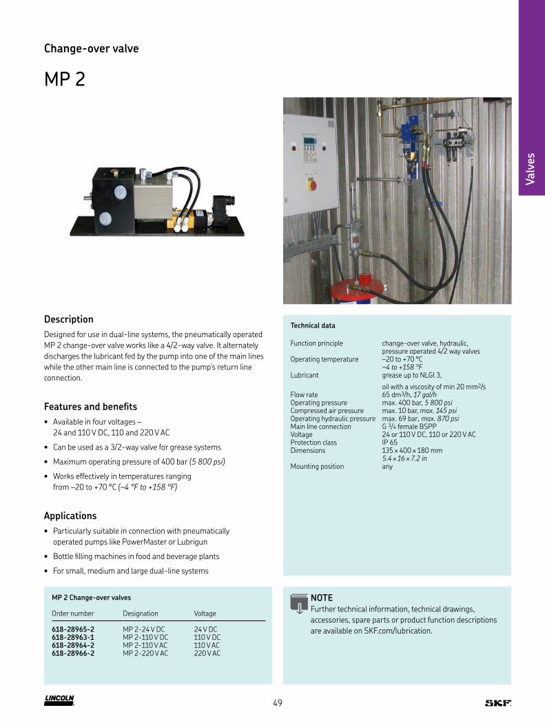
MP 2
Description
Designed for use in dual-line systems, the pneumatically operated
MP 2 change-over valve works like a 4/2-way valve It alternately
discharges the lubricant fed by the pump into one of the main lines
while the other main line is connected to the pump’s return line
connection
Features and beneits
• Available in four voltages –
24 and 110 V DC, 110 and 220 V AC
• Can be used as a 3/2-way valve for grease systems
• Maximum operating pressure of 400 bar (5 800 psi)
• Works effectively in temperatures ranging
from –20 to +70 °C (–4 °F to +158 °F)
Applications
• Particularly suitable in connection with pneumatically
operated pumps like PowerMaster or Lubrigun
• Bottle illing machines in food and beverage plants
• For small, medium and large dual-line systems
Technical data
Function principle change-over valve, hydraulic, pressure operated 4/2 way valves
Operating temperature –20 to +70 °C–4 to +158 °F
Lubricant grease up to NLGI 3,
oil with a viscosity of min 20 mm2/sFlow rate 65 dm3/h, 17 gal/hOperating pressure max 400 bar, 5 800 psiCompressed air pressure max 10 bar, max. 145 psi Operating hydraulic pressure max 69 bar, max. 870 psiMain line connection G 3/4 female BSPPVoltage 24 or 110 V DC, 110 or 220 V ACProtection class IP 65Dimensions 135 × 400 × 180 mm
5.4 × 16 × 7.2 inMounting position any
NOTE Further technical information, technical drawings,
accessories, spare parts or product function descriptions
are available on SKF com/lubrication
MP 2 Change-over valves
Order number Designation Voltage
618-28965-2 MP 2-24 V DC 24 V DC618-28963-1 MP 2-110 V DC 110 V DC618-28964-2 MP 2-110 V AC 110 V AC618-28966-2 MP 2-220 V AC 220 V AC
49

Valv
es
Change-over valve
E-VALV
Description
The electrically operated line valve E-VALV is a modular 3/2 valve
in which each module has an internal pressure and tank connection
The beneit of the modular structure is that it enables the longest
possible pressure discharge time for each lubrication line in a single-
or dual-line system Several lines or channels can be installed with
the same valve assembly
Features and beneits
• Cost eficient electrically operated change-over valve
• Compact and modular design (easy reduce- or extendable)
• System performance optimizing because it enables long
pressure discharge time for each lubrication line
Applications
• General industry
• Mining industry
• Steel industry
• Food and beverage
• Cement industry
Technical data
Function principle electrically operated change-over valve
Operating temperature -10 to +50 °C 14 to +122 °F
Lubricant grease up to NLGI 2Operating pressure max 300 bar
max. 4 351 psiAvailable designs 2, 4, 6, 8, 10, 12, 14 valves (for dual line)Inlet and outlet connection 12 mm or 1/2 inch pipe connectionSupply voltage 24 V DCProtection class IP 67Dimensions 59 × 100 × 230 mm
2.32 × 3.93 × 9.05 inMounting position any
NOTE Further technical information, technical drawings,
accessories, spare parts or product function descriptions
are available on SKF com/lubrication
OEVL2BEN
50

Valv
es
Order information
Order number 1) Designation Number of valves Description Lubricant line Voltage
∅ 24 V DC
12375470 E-VALV-L2-24 2 Change-over valve L2 12 mm •
12375475 E-VALV-L2-24-U 2 Change-over valve L2 (US) 1/2 in •
12375490 E-VALV-L4-24 4 Change-over valve L4 12 mm •
12375495 E-VALV-L4-24-U 4 Change-over valve L4 (US) 1/2 in •
Change-over valve
E-VALV
1) Futher designs available on request
51

Valv
es
Technical data
Function principle change-over valve, electro-pneumatically operated
Operating temperature 0 to +50 °C, +32 to +122 °FOperating pressure max 300 bar, 4 350 psiPressure air supply 2,0 to 4,5 bar, 29 to 65 psiAir low max 300 l/minLubricant grease: up to NLGI 2
oil: 5 000 mm2/sElectrical connections control voltage: 24 V DC
power supply: 115/230 V AC 50/60 HzProtection class IP 65Dimensions depending on the model
min 650 × 130 × 130 mm max 1 020 × 130 × 130 mmmin. 25.6 × 5.12 × 5.12 in max. 40.16 × 5.12 × 5.12 in
Mounting position vertical
Change-over valve
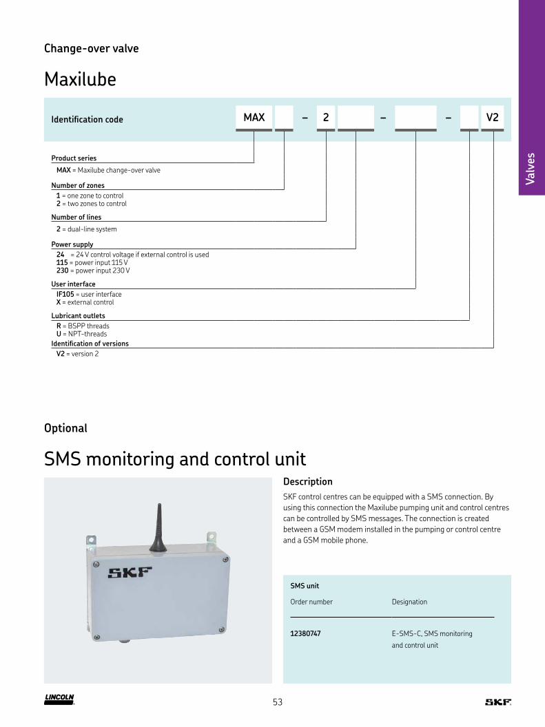
Maxilube
Description
Maxilube change-over valve is an essential part of heavy industry
dual-line systems It has proven its reliability in various applications
throughout Pulp & Paper, Steel and Mining industries over past dec-
ades The Maxilube is a compact solution including the main feature
as change-over valve but also often with integrated IF-105 control
feature The Maxilube is an air-operated change-over valve unit and
it is a vital part of dual line pumping centre together with a barrel
pump (MPB, etc ) package and a pressure air regulator But even if it
is often used in dual line systems it can also be used in single line and
progressive systems There are multiple control options for Maxilube
unit such
as the integrated control unit IF-105, an external control unit like
ST-2240-LUB or control by customer’s DCS There is also an option
to monitor Maxilube unit with an external control box which utilizes
SMS technology
Features and beneits
• Reliable, trouble-free operation
• Suitable for lubricants up to NLGI 2
• Available with integrated control IF-105
• Compact and rugged heavy duty design
• Includes control features for spray applications
Applications
• Heavy industry
• Pulp and paper industry
• Mining and steel industry
NOTE Further technical information, technical drawings,
accessories, spare parts or product function descriptions
are available on SKF com/lubrication:
PUB 06414/2 EN
52
Valv
es
Change-over valve
Maxilube
Identiication code MAX – 2 – – V2
Product series
MAX = Maxilube change-over valve
Number of zones
1 = one zone to control 2 = two zones to control
Number of lines
2 = dual-line system
Power supply
24 = 24 V control voltage if external control is used 115 = power input 115 V 230 = power input 230 V
User interface
IF105 = user interface X = external control
Lubricant outlets
R = BSPP threads U = NPT-threads
Identiication of versions
V2 = version 2
Optional
SMS monitoring and control unitDescription
SKF control centres can be equipped with a SMS connection By
using this connection the Maxilube pumping unit and control centres
can be controlled by SMS messages The connection is created
between a GSM modem installed in the pumping or control centre
and a GSM mobile phone
SMS unit
Order number Designation
12380747 E-SMS-C, SMS monitoring
and control unit
53

Valv
es
Technical data
Function principle change-over valve, electrically operated 4/3 way valve
Operating temperature –25 to +70 °C, –13 to +158 °FLubricant grease up to NLGI 3Flow rate max 400 l/h, 105 gal/hOperating pressure max 400 bar, max. 5 800 psiMain line connection G 3/4 BSPPElectrical connection bayonet plug DIN 72585Operating voltage 24 V DC or 230 V ACProtection class IP 65Dimensions 220 × 238 × 180 mm
8.64 × 9.35 × 7.07 inMounting position any
Change-over valve
EMU 3
Description
The electrically operated EMU 3 change-over valve is designed for
use with dual-line systems It is particularly suitable for extended
dual-line systems in combination with pneumatically operated
supply pumps with large low rates
Features and beneits
• Features mid position with option to relieve both main lines
toward the pump reservoir during pause time
• System components are pressurized for shorter time periods
and have a longer service life
• Risk of bleeding (soap and oil separation) is reduced
• Large connection thread and line distance allow
larger tube diameters up to 30 mm (1 1/4 in)
Applications
• Continuous casting machines in steel industry
• Bottle illing machines in food and beverage plants
with a few thousand lubrication points
• Large bucket wheel excavators in mining and
basic materials industry
NOTE Further technical information, technical drawings,
accessories, spare parts or product function descriptions
are available on SKF com/lubrication:
951-171-001 EN
54

Valv
es
Change-over valve
EMU 3
Order information
Order number Designation Voltage Hydraulic connection ports
24 V DC 230 V AC
EMU-03-00-0000+924 EMU 3 • – no connection port closed
EMU-03-00-0000+1KF EMU 3 – • no connection port closed
55
Valv
es
Shut-off (way) valve
CLV-2
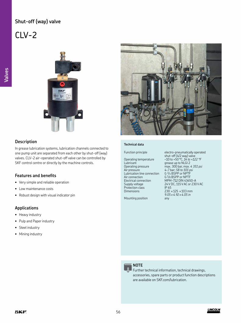
Description
In grease lubrication systems, lubrication channels connected to
one pump unit are separated from each other by shut-off (way)
valves CLV-2 air-operated shut-off valve can be controlled by
SKF control centre or directly by the machine controls
Features and beneits
• Very simple and reliable operation
• Low maintenance costs
• Robust design with visual indicator pin
Applications
• Heavy industry
• Pulp and Paper industry
• Steel industry
• Mining industry
Technical data
Function principle electro-pneumatically operated shut-off (4/2 way) valve
Operating temperature –10 to +50 °C, 14 to +122 °FLubricant grease up to NLGI 2Operating pressure max 300 bar, max. 4 351 psiAir pressure 4–7 bar; 58 to 101 psiLubrication line connection G 3/4 BSPP or NPTFAir connection G 1/8 BSPP or NPTFElectrical connection MPM-712 DIN 43650-ASupply voltage 24 V DC, 115 V AC or 230 V ACProtection class IP 65Dimensions 230 × 125 × 103 mm
9.05 × 4.92 × 4.05 inMounting position any
NOTE Further technical information, technical drawings,
accessories, spare parts or product function descriptions
are available on SKF com/lubrication
56
Valv
es
Order information
Order number Designation Voltage
24 V DC 115 V AC 230 V AC
12385860 CLV-2-24-NC shut-off valve • – –12385865 CLV-2-24-NO shut-off valve • – –12385900 CLV-2-24-NC-U shut-off valve • – –12385950 CLV-2-24-NO-U shut-off valve • – –
12385880 CLV-2-230-NC shut-off valve – – •12385885 CLV-2-230-NO shut-off valve – – •
12385550 CLV-2-115-NC-U shut-off valve – • –12385600 CLV-2-115-NO-U shut-off valve – • –
Shut-off (way) valve
CLV-2
57
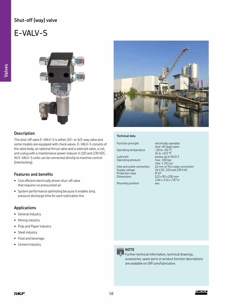
Valv
es
Shut-off (way) valve
E-VALV-S
Description
The shut-off valve E-VALV-S is either 2/2- or 4/2-way valve and
some models are equipped with check valves E-VALV-S consists of
the valve body, an optional thrust valve and a solenoid valve, a coil,
and a plug with a maintenance power reducer in 110 and 230 VDC
All E-VALV-S units can be connected directly to machine control
(interlocking)
Features and beneits
• Cost eficient electrically driven shut-off valve
that requires no pressurized air
• System performance optimizing because it enables long
pressure discharge time for each lubrication line
Applications
• General industry
• Mining industry
• Pulp and Paper industry
• Steel industry
• Food and beverage
• Cement industry
Technical data
Function principle electrically operated shut-off (way) valve
Operating temperature –10 to +50 °C 14 to +122 °F
Lubricant grease up to NLGI 2Operating pressure max 300 bar
max. 4 351 psiInlet and outlet connection 12 mm or 1/2 in pipe connectionSupply voltage 24 V DC, 110 and 230 V ACProtection class IP 67Dimensions 123 × 90 × 200 mm
4.84 × 3.54 × 7.87 inMounting position any
NOTE Further technical information, technical drawings,
accessories, spare parts or product function descriptions
are available on SKF com/lubrication
58

Valv
es
Order information
Order number 1) Designation Description Lubricant line Voltage
∅ 24 V DC 110 V AC 230 V AC
12375780 E-VALV-S2-NC-24 Shut-off valve, normally (de-energized) closed 12 mm • – –
12375785 E-VALV-S2-NC-24-U Shut-off valve, normally (de-energized) closed 1/2 in • – –
12375790 E-VALV-S2-NC-110-U Shut-off valve, normally (de-energized) closed 1/2 in – • –
12375795 E-VALV-S2-NC-230 Shut-off valve, normally (de-energized) closed 12 mm – – •
Shut-off (way) valve
E-VALV-S
1) Futher designs available on request
59
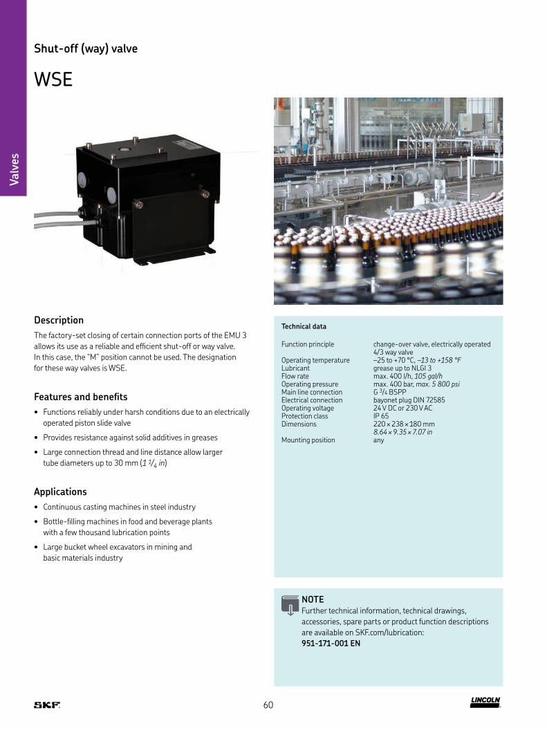
Valv
es
Shut-off (way) valve
WSE
Description
The factory-set closing of certain connection ports of the EMU 3
allows its use as a reliable and eficient shut-off or way valve
In this case, the “M” position cannot be used The designation
for these way valves is WSE
Features and beneits
• Functions reliably under harsh conditions due to an electrically
operated piston slide valve
• Provides resistance against solid additives in greases
• Large connection thread and line distance allow larger
tube diameters up to 30 mm (1 1/4 in)
Applications
• Continuous casting machines in steel industry
• Bottle-illing machines in food and beverage plants
with a few thousand lubrication points
• Large bucket wheel excavators in mining and
basic materials industry
Technical data
Function principle change-over valve, electrically operated 4/3 way valve
Operating temperature –25 to +70 °C, –13 to +158 °FLubricant grease up to NLGI 3Flow rate max 400 l/h, 105 gal/hOperating pressure max 400 bar, max. 5 800 psiMain line connection G 3/4 BSPPElectrical connection bayonet plug DIN 72585Operating voltage 24 V DC or 230 V ACProtection class IP 65Dimensions 220 × 238 × 180 mm
8.64 × 9.35 × 7.07 inMounting position any
NOTE Further technical information, technical drawings,
accessories, spare parts or product function descriptions
are available on SKF com/lubrication:
951-171-001 EN
60

Order information
Order number Designation Voltage Hydraulic connection ports
24 V DC 230 V AC
WSE-22-66-0000+924 WS–E 2/2 way valve • – connection ports B and R closed
WSE-22-66-0000+1KF WS–E 2/2 way valve – • connection ports B and R closed
WSE-32-06-0000+924 WS–E 3/2 way valve • – connection port R closed
WSE-32-06-0000+1KF WS–E 3/2 way valve – • connection port R closed
WSE-32-60-0000+924 WS–E 3/2 way valve • – connection port B closed
WSE-32-60-0000+1KF WS–E 3/2 way valve – • connection port B closed
Shut-off (way) valve
WSE
61

Pre
ssure
sen
sors
62

Mechanical pressure switches
Product Function principle Operation pressure max Supply voltage Page
bar psi V DC V AC
DSB 1 Mechanical pressure switch 300 4 350 36 30 64
Overview of pressure sensors
Electric pressure switches/transmitter
Product Function principle Operation pressure max Supply voltage Page
bar psi V DC V AC
EDW Electric pressure switch 600 8 700 – – 66
DW Electric pressure switch 175/400 2 465/5 800 24 – 67
BPSG PTA-MOD Electric pressure transmitter for SGA systems 250 3 600 24 – 68
DDS 50/1 Differential pressure switch 400 5 800 24 400/500 69
DPC 1 End-of-line pressure switch unit 400 5 800 24 – 70
Pre
ssure
sen
sors
63

Pre
ssure
sen
sors
Technical data
Function principle mechanical piston pressure switchOperating temperature –25 to +80 °C,
–13 to +132 °FOperating pressure max 300 bar, 4 350 psiLubricant oil and grease NLGI 1 and 2Breaking capacity, ohm load max 1,2 VASupply voltage max 30 V AC/36 V DCSupply current min 1 mA, max 50 mAType of contact change-over
Connection method clampsMechanical service life 105 switching cyclesHousing material aluminium, anodizedContact material silver alloy, hard gold platingConnector socket 3+PE DIN EN 175 301-803 AConnection G 1/4
Dimensions 60 × 76 × 105 mm 2.36 × 3 × 4.13 in
Protection class IP 65Mounting position anyCertiication Germanischer Loyd (GL) certiication
Pressure switch
DSB 1
Description
Product series DSB consists of mechanical-piston pressure switches
designed for use with NLGI Grade 1-2 greases The location of the
actuating piston inside the pressure switch housing helps to ensure
a continuous exchange of grease around the measuring point This
reliably prevents the same grease from being pressurized repeatedly,
which could cause lubricant soap and oil separation, also known as
grease bleeding Based on the application, the pressure switch can
be conigured as a single or double design and with or without a
measurement connector or pressure gauge The pressure switch
generally is installed upstream of the last lubricant distributor
Features and beneits
• Available in pre-adjusted versions ranging
from 20 to 300 bar (290 to 4 350 psi)
• Prevents oil separation-related faults
• Reliable micro-switch technology with change-over
contact (NO and NC)
• Includes built-in manifold for continuous lubricant low
without dead volume
• IP 65 protection rating, corrosivity category C3 or C5M
Applications
• General industry
• Steel industry
• Wind industry
• Mining industry
• Heavy industry
NOTE Further technical information, technical drawings,
accessories, spare parts or product function descriptions
are available on SKF com/lubrication:
1-1701 EN
64
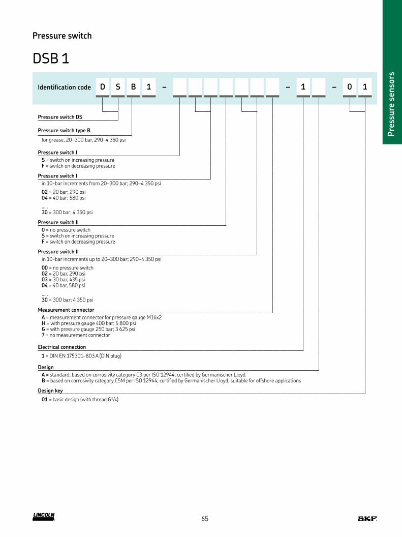
Pre
ssure
sen
sors
Pressure switch
DSB 1
Identiication code D S B 1 – – 1 – 0 1
Pressure switch DS
Pressure switch type B
for grease, 20–300 bar, 290–4 350 psi
Pressure switch I
S = switch on increasing pressure F = switch on decreasing pressure
Pressure switch I
in 10-bar increments from 20–300 bar; 290–4 350 psi
02 = 20 bar; 290 psi04 = 40 bar; 580 psi
30 = 300 bar; 4 350 psi
Pressure switch II
0 = no pressure switch S = switch on increasing pressure F = switch on decreasing pressure
Pressure switch II
in 10-bar increments up to 20–300 bar; 290–4 350 psi
00 = no pressure switch 02 = 20 bar, 290 psi 03 = 30 bar, 435 psi 04 = 40 bar, 580 psi
30 = 300 bar; 4 350 psi
Measurement connector
A = measurement connector for pressure gauge M16x2 H = with pressure gauge 400 bar; 5 800 psi G = with pressure gauge 250 bar; 3 625 psi7 = no measurement connector
Electrical connection
1 = DIN EN 175301-803 A (DIN plug)
Design
A = standard, based on corrosivity category C3 per ISO 12944, certiied by Germanischer Lloyd B = based on corrosivity category C5M per ISO 12944, certiied by Germanischer Lloyd, suitable for offshore applications
Design key
01 = basic design (with thread G1/4)
65

Pre
ssure
sen
sors
Technical data
Function principle electronic pressure switch with 4-digit 7-segment LED display
Operating temperature –25 to +85 °C -13 to +185 °F
Operating pressure 0–600 bar, 0–8 700 psiMain line connection G 1/4 maleElectrical connections 4 pin plug, M 12 × 1Supply voltage 18–36 V DCDimensions 150 × 250 × 60 mm
5.9 × 9.9 × 2.4 in
Protection class IP 67Mounting position any
End - of - line pressure unit
EDW
Description
EDW end-of-line pressure switches are key components in a
dual-line lubrication system Designed to monitor the system,
these switches detect the pressure at the end of the respective
main line and start the change-over procedure If the pressure at
the end of the line is not reached within a speciic period of time,
a fault signal will be generated at the electronic control unit
Features and beneits
• Controls proper functioning of the pump and
change-over unit
• Monitors for leaks in the tube line system
• Available with limit switches or with
electronic pressure switches with LED display
• Proven, rigid design for tough conditions
Applications
• Large dual-line systems
• Steel mills
• Cement plants
• Minerals and mining
NOTE Further technical information, technical drawings,
accessories, spare parts or product function descriptions
are available on SKF com/lubrication
Order information
Order number Designation
632-36501-1 EDW end-of-line pressure unit with limit switches and pressure gauges
632-36627-3 EDW end-of-line pressure unit with electronic pressure switches with LED display
66

Pre
ssure
sen
sors
Electric pressure switch
DW
Description
Electric pressure switches are used to monitor the operating
pressure of the pump They are installed at the pressure outlet of
the pump and will switch off the pump if an overpressure occurs
downstream in the system
Features and beneits
• Protects the system from damage
caused by overpressure
• All parameters can be set by keypad
• Adjustable keypad lock
• Rugged construction, vibration and shock-proof
• Long-term stability
Applications
• Dual-line pumps
• Steel mills
• Cement plants
• Minerals and mining
Technical data
Function principle electric pressure switchOperating temperature –25 to +85 °C, +13 to +185 °FOperating pressure 0–600 bar, 0–8 700 psiInput data measuring range 0–600 bar; 0–8 700 psi
overload pressure: 750 bar; 10 870 psiburst pressure: 800 bar; 11 600 psi
Output data accuracy >=0,5% full scaleAnalog output signal 4–20 mASwitching output type PNP transistor output
switching current max 0,5 ASupply voltage 18–36 V DCHydraulic connection G 1/4
Protection class IP 67
Dimensions 94 × 34 × 49 mm; 3.7 × 1.34 × 1.93 in
Mounting position any
Order information
Order number Designation
623-37567-1 Electric pressure switch with transducer kit for 40 and 100 l, 10 and 26 gal, reservoir versions, includes electronic pressure and digital display
NOTE Further technical information, technical drawings,
accessories, spare parts or product function descriptions
are available on SKF com/lubrication
67

Pre
ssure
sen
sors
Technical data
Function principle monitoring deviceOperating temperature –30 to +85 °C,
–22 to +185 °FOperating pressure 0–250 bar, 0–3 600 psiMaterials metering device:
carbon steel galvanized or stainless steel transmitter: stainless steel
Supply voltage 24 (10-30) V DCOutput connection 4 20 mA, 2 wire cableProtection class IP 67Dimensions 110 × 105 × 33 mm
4.33 × 4.13 × 1.29 inMounting position any
Pressure transmitter
BPSG PTA-MOD
Description
The BPSG2-PTA-MOD pressure transmitter assembly features a
modular design for easy installation and service Located between
the base plate and metering device, the assembly’s pressure trans-
mitters measure the pressure of passing lubricant and notify the
control unit These end-of-line (main lines) pressures can also be
monitored from the lubrication system’s control unit
Features and beneits
• Simple to install; no extra parts required
• Suitable for oils and greases up to NLGI Grade 2
• Helps to ensure that fresh lubricant lows
through transmitters; no clogging
• Operates effectively in a wide range of temperatures
• IP 67 protection rating (for models with enclosure)
Applications
• Paper industry
• Steel industry
• Heavy industry
NOTE Further technical information, technical drawings,
accessories, spare parts or product function descriptions
are available on SKF com/lubrication:
PUB LS/P8 11277 EN
Order information
Order number Designation Carbon steel zinc coated
Stainless steel
12385333 BSPG2-PTA-MOD-D-ZN • –
12385331 BSPG2-PTA-MOD-D-SS – •
68
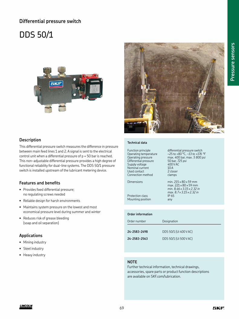
Pre
ssure
sen
sors
Differential pressure switch
DDS 50/1
Description
This differential pressure switch measures the difference in pressure
between main feed lines 1 and 2 A signal is sent to the electrical
control unit when a differential pressure of p = 50 bar is reached
This non-adjustable differential pressure provides a high degree of
functional reliability for dual-line systems The DDS 50/1 pressure
switch is installed upstream of the lubricant metering device
Features and beneits
• Provides ixed differential pressure;
no regulating screws needed
• Reliable design for harsh environments
• Maintains system pressure on the lowest and most
economical pressure level during summer and winter
• Reduces risk of grease bleeding
(soap and oil separation)
Applications
• Mining industry
• Steel industry
• Heavy industry
Technical data
Function principle differential pressure switchOperating temperature –25 to +80 °C, –13 to +176 °FOperating pressure max 400 bar, max 5 800 psiDifferential pressure 50 bar, 725 psiSupply voltage 400 V ACNominal current 10 AUsed contact 2 closerConnection method clamps
Dimensions min 215 × 80 × 59 mm max 221 × 80 × 59 mmmin. 8.46 × 3.15 × 2.32 in max. 8.7 × 3.15 × 2.32 in
Protection class IP 65Mounting position any
Order information
Order number Designation
24-2583-2498 DDS 50/1 (Ui 400 V AC)
24-2583-2563 DDS 50/1 (Ui 500 V AC)
NOTE Further technical information, technical drawings,
accessories, spare parts or product function descriptions
are available on SKF com/lubrication
69
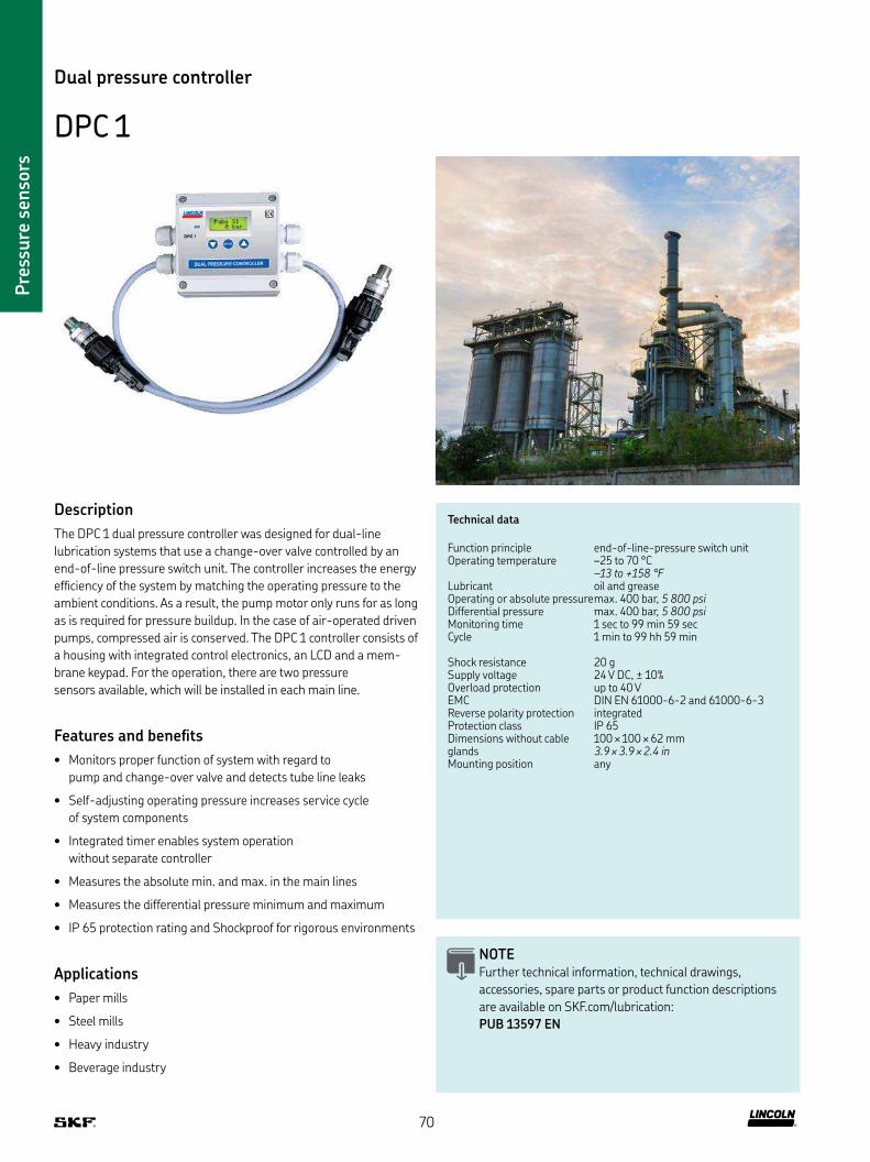
Pre
ssure
sen
sors
Technical data
Function principle end-of-line-pressure switch unitOperating temperature –25 to 70 °C
–13 to +158 °FLubricant oil and greaseOperating or absolute pressuremax 400 bar, 5 800 psiDifferential pressure max 400 bar, 5 800 psiMonitoring time 1 sec to 99 min 59 secCycle 1 min to 99 hh 59 min
Shock resistance 20 gSupply voltage 24 V DC, ± 10%Overload protection up to 40 VEMC DIN EN 61000-6-2 and 61000-6-3Reverse polarity protection integratedProtection class IP 65Dimensions without cable glands
100 × 100 × 62 mm 3.9 × 3.9 × 2.4 in
Mounting position any
Dual pressure controller
DPC 1
Description
The DPC 1 dual pressure controller was designed for dual-line
lubrication systems that use a change-over valve controlled by an
end-of-line pressure switch unit The controller increases the energy
eficiency of the system by matching the operating pressure to the
ambient conditions As a result, the pump motor only runs for as long
as is required for pressure buildup In the case of air-operated driven
pumps, compressed air is conserved The DPC 1 controller consists of
a housing with integrated control electronics, an LCD and a mem-
brane keypad For the operation, there are two pressure
sensors available, which will be installed in each main line
Features and beneits
• Monitors proper function of system with regard to
pump and change-over valve and detects tube line leaks
• Self-adjusting operating pressure increases service cycle
of system components
• Integrated timer enables system operation
without separate controller
• Measures the absolute min and max in the main lines
• Measures the differential pressure minimum and maximum
• IP 65 protection rating and Shockproof for rigorous environments
Applications
• Paper mills
• Steel mills
• Heavy industry
• Beverage industry
NOTE Further technical information, technical drawings,
accessories, spare parts or product function descriptions
are available on SKF com/lubrication:
PUB 13597 EN
70
Pre
ssure
sen
sors
Dual pressure controller
DPC 1
Order information
Order number Designation
234-10723-3 DCP 1 end-of-line-pressure switch unit234-10663-7 pressure sensor
(two required for use with DPC 1)
DPC 1 accessories
Order number Designation
236-10980-3 motor starter 1,0 A (e g for pump unit ZPU 02)236-10980-4 motor starter 1,6 A (e g for pump unit ZPU 08)236-10980-5 motor starter 4,0 A (e g for pump unit ZPU 24)
1) motor starters to operate electrically driven pumps without separate controller
71
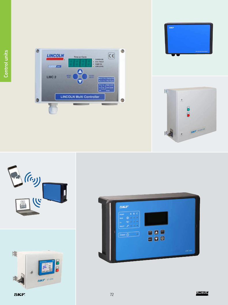
Contr
ol u
nit
s
72
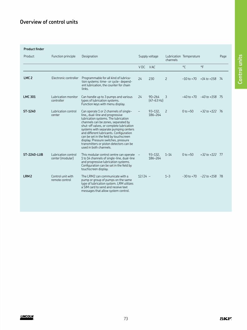
Product inder
Product Function principle Designation Supply voltage Lubrication Temperature Pagechannels
V DC V AC °C °F
LMC 2 Electronic controller Programmable for all kind of lubrica-tion systems: time- or cycle- depend-ent lubrication, the counter for chain links
24 230 2 –10 to +70 +14 to +158 74
LMC 301 Lubrication monitor controller
Can handle up to 3 pumps and various types of lubrication systems Function keys with menu display
24 90–264 (47–63 Hz)
3 –40 to +70 -40 to +158 75
ST-1240 Lubrication control center
Can operate 1 or 2 channels of single-line,, dual-line and progressive lubrication systems The lubrication channels can be zones, separated by shut-off valves, or complete lubrication systems with separate pumping centers and different lubricants Coniguration can be set in the ield by touchscreen display Pressure switches, pressure transmitters or piston detectors can be used in both channels
– 93–132, 186–264
2 0 to +50 +32 to +122 76
ST-2240-LUB Lubrication control center (modular)
This modular control centre can operate 1 to 14 channels of single-line, dual-line and progressive lubrication systems Coniguration can be set in the ield by touchscreen display
– 93–132, 186–264
1–14 0 to +50 +32 to +122 77
LRM 2 Control unit with remote control
The LRM2 can communicate with a pump or group of pumps on the same type of lubrication system LRM utilizes a SIM card to send and receive text messages that allow system control
12 / 24 – 1–3 -30 to +70 -22 to +158 78
Overview of control units
Contr
ol u
nit
s
73

Contr
ol u
nit
s
Technical data
Function principle electronic controllerOperating temperature –10 to +70 °C,
+14 to +158 °FInputs max 8 digital inputsOutputs 4 relay outputs, 1 electronic Supply voltage depending on model
230 V AC, 24 V DCProtection class IP 54Mounting position anyDimensions 200 × 120 × 90 mm
7.9 × 4.7 × 3.5 in
Control units
LMC 2
Description
The LMC is a controller for the electronic management and monitor-
ing of lubrication systems It combines the advantages of a specially
developed printed circuit board (PCB) and a PLC in an economical,
compact unit For dual-line systems, it controls the pump unit,
change-over valve and end-of-line devices
Features and beneits
• Integrated, lexible lubrication programmes
• 8 inputs / 5 outputs –
suitable for complex lubrication systems
• Time- or cycle-dependent control of lubrication intervals
• Can be interfaced with common ield bus systems
Applications
• Lincoln and SKF single-line, dual-line,
multi-line and progressive systems
• Railway lubrication and spray lubrication systems
• Food and beverage
• Chain lubrication systems like Cobra and PMA
NOTE Further technical information, technical drawings,
accessories, spare parts or product function descriptions
are available on SKF com/lubrication:
PUB 14004 EN
Order information
Order number Designation
236–10567–6 LMC2 230 AC (230 V AC)236–10567–5 LMC2 24 DC (24 V DC)
For use with electric driven 3-phase pump; need to order motor starter separately
74

Contr
ol u
nit
s
Control units
LMC 301
NOTE Further technical information, technical drawings,
accessories, spare parts or product function descriptions
are available on SKF com/lubrication:
PUB LS/P2 15967/1 EN
Description
The LMC 301 is a compact, modularly expandable control and
monitoring device The device is equipped with an LCD display
and 6 functional keys for programming, parameter setting and
signalization The user is guided through the setting menu
Additionally, there is a simple-to-use PC software for parameter
setting and diagnostics available
Features and beneits
• Integrated, lexible lubrication programs
• Basic device with 10 digital inputs,
of which two can be used analogously, and eight outputs
• Up to seven extension modules can be added,
whereby each module has 10 E 8 A just like the basic device
• Three lubrication pumps can be controlled and monitored,
each of which provides up to three lubrication circuits
• Single modules are connected by a bus interface
Applications
• Cement industry
• Steel industry
• Mining – stationary and mobile excavators
• Food and beverage
Technical data
Function principle electronic controllerOperating temperature V AC:
–10 to +50 °C, +14 to +122 °F
V DC: –40 to +70 °C, -40 to +158 °F
Inputs 10 count, short-circuit proof, 2 with analog
Outputs 8 count, relay outputs NO-contact 8 A, 2 of which up to 20 A
Supply Voltage depending on model 90-264 V AC, 24 V DC ±20%
Protection class IP 65Mounting position verticalDimensions 270 × 170 × 90 mm
10.7 × 6.7x 3.5 in
Order information
Order number Designation
86500 LMC 301: 24 V DC, master, incl LCD display86501 LMC 301: 100–240 V AC, master, incl LCD display
75
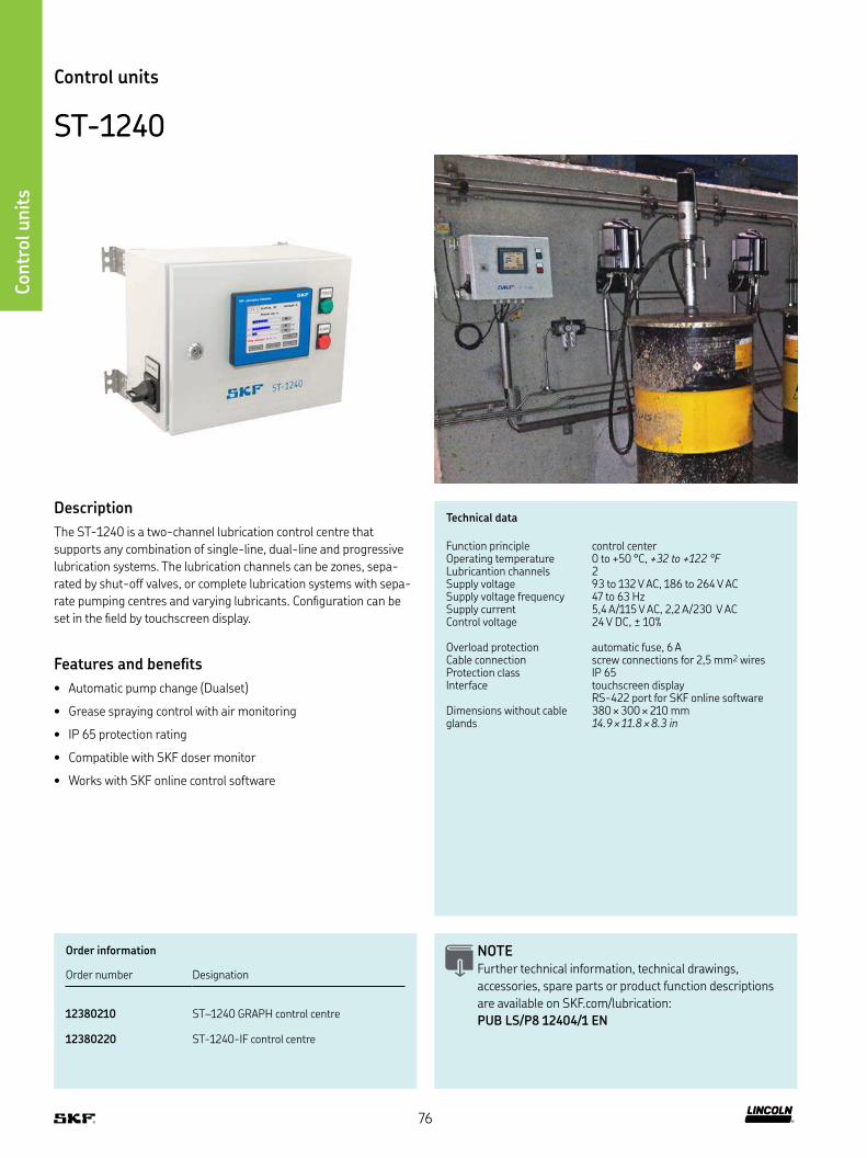
Contr
ol u
nit
s
Technical data
Function principle control centerOperating temperature 0 to +50 °C, +32 to +122 °FLubricantion channels 2Supply voltage 93 to 132 V AC, 186 to 264 V ACSupply voltage frequency 47 to 63 HzSupply current 5,4 A/115 V AC, 2,2 A/230 V ACControl voltage 24 V DC, ± 10%
Overload protection automatic fuse, 6 ACable connection screw connections for 2,5 mm2 wiresProtection class IP 65Interface touchscreen display
RS-422 port for SKF online softwareDimensions without cable glands
380 × 300 × 210 mm 14.9 × 11.8 × 8.3 in
Control units
ST-1240
Description
The ST-1240 is a two-channel lubrication control centre that
supports any combination of single-line, dual-line and progressive
lubrication systems The lubrication channels can be zones, sepa-
rated by shut-off valves, or complete lubrication systems with sepa-
rate pumping centres and varying lubricants Coniguration can be
set in the ield by touchscreen display
Features and beneits
• Automatic pump change (Dualset)
• Grease spraying control with air monitoring
• IP 65 protection rating
• Compatible with SKF doser monitor
• Works with SKF online control software
NOTE Further technical information, technical drawings,
accessories, spare parts or product function descriptions
are available on SKF com/lubrication:
PUB LS/P8 12404/1 EN
Order information
Order number Designation
12380210 ST–1240 GRAPH control centre
12380220 ST-1240-IF control centre
76

Contr
ol u
nit
s
Control units
ST-2240-LUB
Description
ST-2240-LUB-6 and ST-2240-LUB-14 lubrication control centers
are suitable for use in dual-line lubrication systems, as well as sin-
gle-line and progressive systems These units have a touchscreen
display and are only differentiated by the cabinet size and maximum
number of lubrication channels served The ST-2240-LUB-6 con-
trols up to 6 separate lubrication channels, while ST-2240-LUB-14
controls up to 14 channels, each having independent lubrication
parameters and/allows use of different lubricants if required The
lubrication system is adjustable at ield site by adding or reducing
channel modules, and coniguration can be changed in the ield by
the user Pressure switches and transmitters or piston detectors can
be used in all channels Also the new lubricant low level ultrasonic
sensor is supported
Features and beneits
• Versatile and durable, automatic pump change (Dualset)
• Modular units provide easy system modiication
• Compatible with ultrasonic low level sensor
• Grease spraying control with air monitoring
• Compatible with SKF doser monitor
NOTE Further technical information, technical drawings,
accessories, spare parts or product function descriptions
are available on SKF com/lubrication:
PUB LS/P2 17950 EN
Technical data
Function principle control centerOperating temperature 0 to +50 °C, +32 to +122 °FLubricant channels 1-14Supply voltage 115/230 V AC, automatic range selectionSupply voltage frequency 47 to 63 HzControl voltage 24 V DC, ± 10 %Overload protection automatic fuse, 6 ACable connection screw terminals for 2,5 mm2 wiresProtection class IP 65Interface 5 7” TFT touch screen , 320 × 240,
64k colors, ethernet and USB port mobile app for monitoring
Data logging Log iles on USB memoryFieldbus ModbusTCP slave,
other protocols on requestAlarm Outputs relays K1 & K2: potential-free change
over contact; maximum load 230 V/1 A; channel modules: potential-free contact; maximum load 50 V DC/1A
Dimensions 600 × 600 × 250 mm 23.6 × 23.6 × 9.8 in
Order information
Order number Designation
12380760 ST-2240-LUB-6 control center
12380765 ST-2240-LUB-14 control center
12501270 CM channel module
77
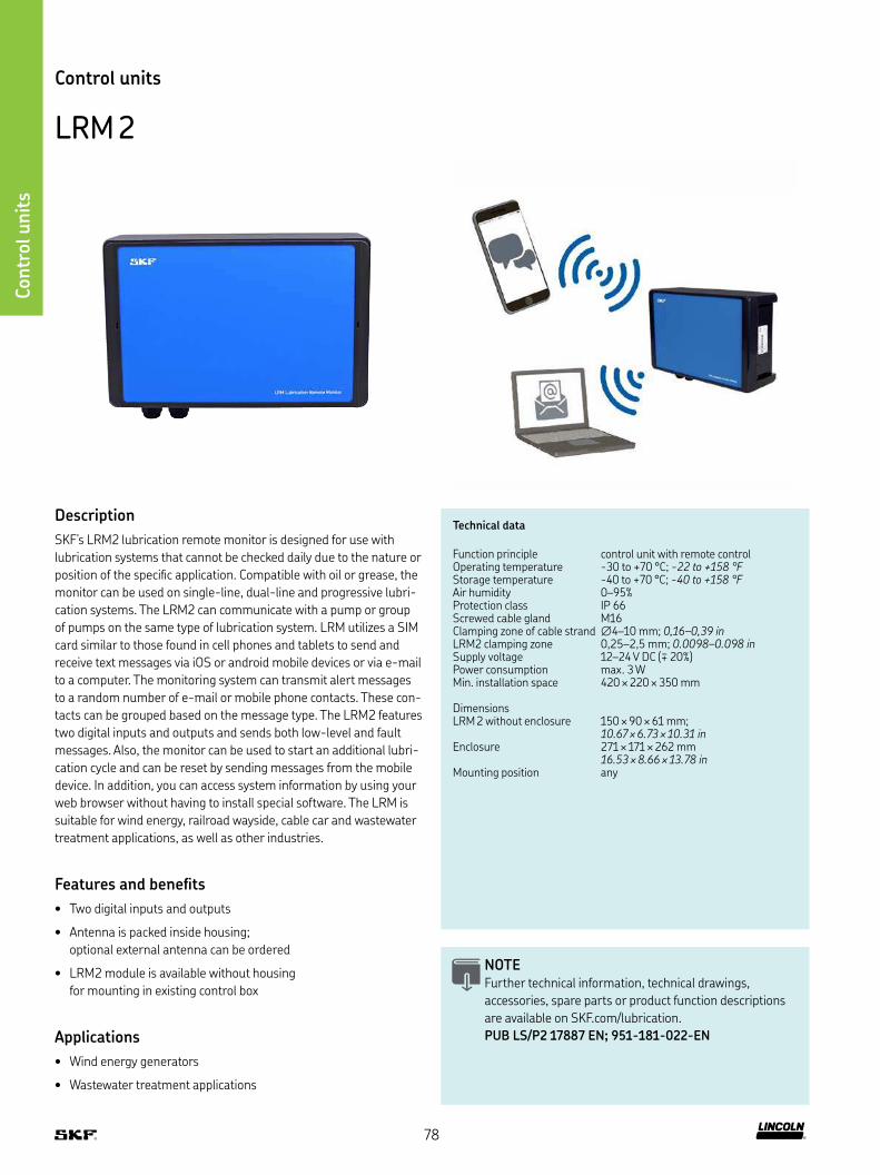
Contr
ol u
nit
s
Control units
LRM 2
Technical data
Function principle control unit with remote controlOperating temperature -30 to +70 °C; -22 to +158 °FStorage temperature -40 to +70 °C; -40 to +158 °FAir humidity 0–95%Protection class IP 66Screwed cable gland M16Clamping zone of cable strand ∅4–10 mm; 0,16–0,39 inLRM2 clamping zone 0,25–2,5 mm; 0.0098–0.098 inSupply voltage 12–24 V DC (∓ 20%)Power consumption max 3 WMin installation space 420 × 220 × 350 mm
DimensionsLRM 2 without enclosure 150 × 90 × 61 mm;
10.67 × 6.73 × 10.31 inEnclosure 271 × 171 × 262 mm
16.53 × 8.66 × 13.78 inMounting position any
Description
SKF’s LRM2 lubrication remote monitor is designed for use with
lubrication systems that cannot be checked daily due to the nature or
position of the speciic application Compatible with oil or grease, the
monitor can be used on single-line, dual-line and progressive lubri-
cation systems The LRM2 can communicate with a pump or group
of pumps on the same type of lubrication system LRM utilizes a SIM
card similar to those found in cell phones and tablets to send and
receive text messages via iOS or android mobile devices or via e-mail
to a computer The monitoring system can transmit alert messages
to a random number of e-mail or mobile phone contacts These con-
tacts can be grouped based on the message type The LRM2 features
two digital inputs and outputs and sends both low-level and fault
messages Also, the monitor can be used to start an additional lubri-
cation cycle and can be reset by sending messages from the mobile
device In addition, you can access system information by using your
web browser without having to install special software The LRM is
suitable for wind energy, railroad wayside, cable car and wastewater
treatment applications, as well as other industries
Features and beneits
• Two digital inputs and outputs
• Antenna is packed inside housing;
optional external antenna can be ordered
• LRM2 module is available without housing
for mounting in existing control box
Applications
• Wind energy generators
• Wastewater treatment applications
NOTE Further technical information, technical drawings,
accessories, spare parts or product function descriptions
are available on SKF com/lubrication
PUB LS/P2 17887 EN; 951-181-022-EN
78
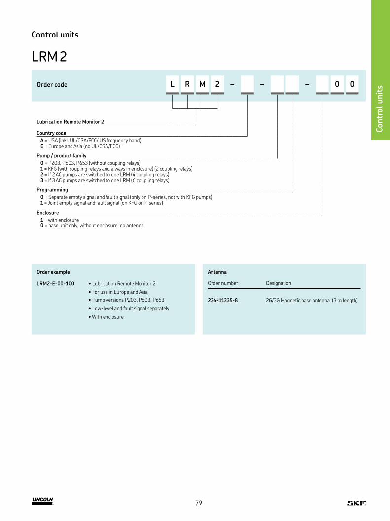
Contr
ol u
nit
s
Control units
LRM 2
Order code L R M 2 – – – 0 0
Lubrication Remote Monitor 2
Country code
A = USA (inkl UL/CSA/FCC/ US frequency band) E = Europe and Asia (no UL/CSA/FCC)
Pump / product family
0 = P203, P603, P653 (without coupling relays) 1 = KFG (with coupling relays and always in enclosure) (2 coupling relays) 2 = If 2 AC pumps are switched to one LRM (4 coupling relays) 3 = If 3 AC pumps are switched to one LRM (6 coupling relays)
Programming
0 = Separate empty signal and fault signal (only on P-series, not with KFG pumps)1 = Joint empty signal and fault signal (on KFG or P-series)
Enclosure
1 = with enclosure 0 = base unit only, without enclosure, no antenna
Order example
LRM2-E-00-100 • Lubrication Remote Monitor 2
• For use in Europe and Asia
• Pump versions P203, P603, P653
• Low-level and fault signal separately
• With enclosure
Antenna
Order number Designation
236-11335-8 2G/3G Magnetic base antenna (3 m length)
79

Index
303-17512-1 40
303-19351-1 32
303-19352-1 32
303-19354-1 32
303-19356-1 32
303-19357-1 32
303-19359-1 32
303-19374-1 32
303-19375-1 32
303-19759-1 37
303-19760-1 40
303-19809-1 40
420-22139-1 37
420-22140-1 37
420-22140-1 40
420-23628-1 32
420-23790-1 32
420-23872-1 37
420-24832-1 37
420-24832-1 40
432-21791-1 33
432-21791-1 37
432-21791-1 41
432-21792-1 33
432-21792-1 37
432-21792-1 41
432-21793-1 33
432-21793-1 37
432-21793-1 41
432-21794-1 33
432-21794-1 37
432-21794-1 41
432-23698-1 33
432-23699-1 33
432-23700-1 33
432-23701-1 33
520-33073-1 37
24-2583-2498 69
24-2583-2563 69
223-13052-1 11
223-13052-1 33
223-13052-1 36
223-13052-1 41
223-13052-2 11
223-13052-2 33
223-13052-2 36
223-13052-2 41
223-13052-3 11
223-13052-3 33
223-13052-3 36
223-13052-3 41
234-10663-7 71
234-10723-3 71
236–10567–5 74
236–10567–6 74
236-10980-3 71
236-10980-4 71
236-10980-5 71
236-11335-8 79
303-16106-1 40
303-16224-1 37
303-16283-1 37
303-16694-1 37
303-16695-1 37
303-16696-1 37
303-16698-1 37
303-16760-1 37
303-17505-1 37
303-17506-1 37
303-17507-1 37
303-17508-1 37
303-17509-1 40
303-17510-1 40
303-17511-1 40
520-33074-1 41
520-33075-1 33
520-33103-1 41
520-33104-1 41
520-33105-1 37
520-33106-1 37
520-33107-1 37
520-33108-1 41
520-33109-1 33
520-33110-1 33
520-33112-1 33
520-33266-1 33
520-33267-1 33
520-33268-1 33
520-33269-1 33
520-33270-1 37
520-33271-1 37
520-33272-1 37
520-33273-1 37
520-33274-1 41
520-33275-1 41
520-33276-1 41
520-33277-1 41
603-41200-1 11
603-41200-2 11
610-40064-2 39
617-28619-1 48
617-28620-1 48
617-28683-1 48
617-36148-9 48
618-28963-1 49
618-28964-2 49
618-28965-2 49
618-28966-2 49
620-27418-1 31
620-27419-1 31
620-27420-1 31
80
Index
620-27421-1 31
620-27422-1 31
620-27423-1 31
620-27424-1 31
620-27425-1 31
620-27438-1 31
620-27439-1 31
620-27440-1 31
620-27441-1 31
620-27442-1 31
620-27443-1 31
620-27444-1 31
620-27445-1 31
620-27488-1 31
620-27489-1 31
620-27490-1 31
620-27491-1 31
620-27492-1 31
620-27493-1 31
620-27494-1 31
620-27495-1 31
620-27496-1 31
620-27497-1 31
620-27498-1 31
620-27499-1 31
620-27500-1 31
620-27501-1 31
620-27502-1 31
620-27503-1 31
620-27766-1 31
620-27767–1 31
620-27768-1 31
620-27769-1 31
620-27770-1 31
620-27771-1 31
620-27772-1 31
620-27773-1 31
620-27857-1 31
620-27858-1 31
620-27859-1 31
620-27860-1 31
620-27861-1 31
620-27862-1 31
620-27863-1 31
620-27864-1 31
620-28366-1 31
620-28367-1 31
620-28374-1 31
620-28376-1 31
620-28391-1 31
620-28392-1 31
620-28393-1 31
620-28394-1 31
620-28409-1 31
620-28410-1 31
620-28411-1 31
620-28412-1 31
620-28413-1 31
620-28414-1 31
620-28415-1 31
620-28416-1 31
620-40015-1 35
620-40015-2 35
620-40015-3 35
620-40015-4 35
620-40015-5 35
620-40015-6 35
620-40015-7 35
620-40015-8 35
620-40022-1 35
620-40022-2 35
620-40022-3 35
620-40022-4 35
620-40022-5 35
620-40022-6 35
620-40022-7 35
620-40022-8 35
620-40023-1 36
620-40023-2 36
620-40023-3 36
620-40023-4 36
620-40023-5 36
620-40023-6 36
620-40023-7 36
620-40023-8 36
620-40024-1 36
620-40024-2 36
620-40024-3 36
620-40024-4 36
620-40024-5 36
620-40024-6 36
620-40024-7 36
620-40024-8 36
620-40025-1 36
620-40025-2 36
620-40025-3 36
620-40025-4 36
620-40025-5 36
620-40025-6 36
620-40025-7 36
620-40025-8 36
620-40026-1 36
620-40026-2 36
620-40026-3 36
620-40026-4 36
620-40026-5 36
620-40026-6 36
620-40026-7 36
620-40026-8 36
620-40027-1 36
620-40027-2 36
81
Index
620-40065-1 39
620-40065-2 39
620-40065-3 39
620-40065-4 39
620-40065-5 39
620-40065-6 39
620-40065-7 39
620-40066-1 39
620-40066-2 39
620-40066-3 39
620-40066-4 39
620-40066-5 39
620-40066-6 39
620-40066-7 39
620-40066-8 39
620-40066-8 39
620-40067-1 39
620-40067-2 39
620-40067-3 39
620-40067-4 39
620-40067-5 39
620-40067-6 39
620-40067-7 39
620-40067-8 39
620-40068-1 39
620-40068-2 39
620-40068-3 39
620-40068-4 39
620-40068-5 39
620-40068-6 39
620-40068-7 39
620-40068-8 39
620-40069-1 39
620-40069-2 39
620-40069-3 39
620-40069-4 39
620-40069-5 39
620-40027-3 36
620-40027-4 36
620-40027-5 36
620-40027-6 36
620-40027-7 36
620-40027-8 36
620-40028-1 36
620-40028-2 36
620-40028-3 36
620-40028-4 36
620-40028-5 36
620-40028-6 36
620-40028-7 36
620-40028-8 36
620-40062-1 39
620-40062-2 39
620-40062-3 39
620-40062-4 39
620-40062-5 39
620-40062-6 39
620-40062-7 39
620-40062-8 39
620-40063-1 39
620-40063-2 39
620-40063-3 39
620-40063-4 39
620-40063-5 39
620-40063-6 39
620-40063-7 39
620-40063-8 39
620-40064-1 39
620-40064-3 39
620-40064-4 39
620-40064-5 39
620-40064-6 39
620-40064-7 39
620-40064-8 39
620-40069-6 39
620-40069-7 39
620-40069-8 39
620-40525-1 35
620-40525-2 35
620-40525-3 35
620-40525-4 35
620-40525-5 35
620-40525-6 35
620-40525-7 35
620-40525-8 35
620-40526-1 39
620-40526-4 39
620-40526-5 39
620-40526-6 39
620-40526-7 39
620-40526-8 39
620-40526-9 39
620-40527-1 39
620-40567-1 35
620-40567-2 35
620-40567-3 35
620-40567-4 35
620-40567-5 35
620-40567-6 35
620-40567-7 35
620-40567-8 35
620-40605-1 36
620-40605-2 36
620-40605-3 36
620-40605-4 36
620-40605-5 36
620-40605-6 36
620-40605-7 36
620-40605-8 36
620-40637-2 39
620-40637-4 39
82

Index
620-40637-6 39
620-40637-8 39
620-40733-1 36
620-40733-2 36
620-40733-3 36
620-40733-4 36
620-40733-5 36
620-40733-6 36
620-40733-7 36
620-40733-8 36
620-40839-1 35
620-40839-2 35
620-40839-3 35
620-40839-4 35
620-40839-5 35
620-40839-6 35
620-40839-7 35
620-40839-8 35
620-40853-1 39
620-40853-2 39
620-40853-3 39
620-40853-4 39
620-40853-6 39
620-40853-8 39
620-40937-2 39
620-40937-4 39
620-40937-6 39
620-40937-8 39
620-41079-2 40
620-41079-3 40
620-41079-4 40
620-41079-5 40
620-41079-6 40
620-41079-7 40
620-41079-8 40
620-41079-9 40
620-41081-1 37
620-41081-1 37
620-41081-2 37
620-41081-4 37
620-41081-5 37
620-41081-6 37
620-41081-7 37
620-41081-8 37
620-41086-1 31
620-41086-2 31
620-41086-3 31
620-41086-4 31
620-41086-5 31
620-41086-6 31
620-41086-7 31
620-41089-2 32
620-41089-4 32
620-41089-6 32
620-41089-8 32
620-41122-1 31
620-41122-2 31
620-41122-3 31
620-41122-4 31
620-41123-2 32
620-41123-4 32
620-41123-6 32
620-41123-8 32
620-41124-1 37
620-41124-2 37
620-41124-3 37
620-41124-4 37
620-41124-6 37
620-41124-7 37
620-41124-8 37
620-41125-1 40
620-41125-2 40
620-41125-3 40
620-41125-4 40
620-41125-5 40
620-41125-6 40
620-41125-7 40
620-41125-8 40
620-41133-1 37
620-41133-3 37
620-41133-5 37
620-41133-7 37
620-41133-9 37
620-41321-1 35
620-41321-2 35
620-41321-3 35
620-41321-4 35
620-41321-5 35
620-41321-6 35
620-41321-7 35
620-41321-8 35
623-37567-1 67
632-36501-1 66
632-36627-3 66
001709 25
001709 27
002004 26
002716 27
082050 24
082054 24
084723 26
84723 27
86500 75
86501 75
274681 25
12371701 23
12371702 23
12375020 21
12375100 21
12375180 21
12375470 51
83
Index
12384700 44
12384750 44
12384800 44
12384850 44
12385331 68
12385333 68
12385550 57
12385600 57
12385860 57
12385865 57
12385880 57
12385885 57
12385900 57
12385950 57
12386350 44
12386400 44
12386560 43
12386610 43
12386660 43
12386710 43
12386760 43
12386810 43
12387160 43
12387210 43
12387260 43
12387310 43
12387360 43
12387410 43
12387460 43
12387470 43
12387510 43
12387520 43
12387525 43
12387530 43
12387560 43
12387570 43
12387610 43
12375475 51
12375490 51
12375495 51
12375780 59
12375785 59
12375790 59
12375795 59
12380210 76
12380220 76
12380747 53
12380760 77
12380765 77
12381280 21
12381285 21
12381290 21
12381381 23
12381382 23
12381383 23
12381384 23
12381385 23
12381386 23
12381700 23
12382666 23
12383250 44
12383300 44
12383350 44
12383400 44
12383450 44
12383500 44
12384300 44
12384350 44
12384400 44
12384450 44
12384500 44
12384550 44
12384600 44
12384650 44
12387620 43
12387625 43
12387630 43
12387660 43
12387670 43
12387680 43
12387685 43
12387710 43
12387720 43
12388110 43
12388160 43
12388184 45
12388188 45
12388192 45
12501270 77
12771677 45
12771678 45
EMU-03-00-0000+1KF 55
EMU-03-00-0000+924 55
LRM2-E-00-100 79
WSE-22-66-0000+1KF 61
WSE-22-66-0000+924 61
WSE-32-06-0000+1KF 61
WSE-32-06-0000+924 61
WSE-32-60-0000+1KF 61
WSE-32-60-0000+924 61
84
Notes
85
Notes
86

Notes
87
!Important information on product usageSKF and Lincoln lubrication systems or their components are not
approved for use with gases, liquefied gases, pressurized gases in solution and fluids with a vapor pressure exceeding normal atmospheric pressure (1 013 mbar) by more than 0,5 bar at their maximum permissible temperature.
skf com | skf com/lubrication | lincolnindustrial com
® SKF and LINCOLN are registered trademarks of the SKF Group
© SKF Group 2019The contents of this publication are the copyright of the publisher and may not be reproduced (even extracts) unless prior written permission is granted Every care has been taken to ensure the accuracy of the information contained in this publication but no liability can be accepted for any loss or damage whether direct, indirect or consequential arising out of the use of the information contained herein
PUB LS/P1 16132 EN · November 2019
Certain image(s) used under license from Shutterstock com