DSU IV ESP - Voice Communications Inc. IV ESP User Manual.pdf · • Appendix B shows the AT...
171
DSU IV ESP Data Service Unit with Embedded SNMP USER MANUAL Part Number Version 1204011L1 DSU IV ESP 1204001L1 ESP 4-wire Switched 56 DBU Card 1204002L1 ESP V.34 DBU Card 1204004L1 ESP ISDN DBU Card 1204005L1 ESP Ethernet Card 61204.011L1-1A May 1997
Transcript of DSU IV ESP - Voice Communications Inc. IV ESP User Manual.pdf · • Appendix B shows the AT...

DSU IV ESPData Service Unit with Embedded SNMP
USER MANUAL
Part Number Version1204011L1 DSU IV ESP1204001L1 ESP 4-wire Switched 56 DBU Card1204002L1 ESP V.34 DBU Card1204004L1 ESP ISDN DBU Card1204005L1 ESP Ethernet Card
61204.011L1-1AMay 1997

Trademark Information:Hayes is a registered trademark of Hayes Microcomputer Products, Inc.Openview is a registered trademark of Hewlett-Packard Company.SunNet Manager is a registered trademark of Sun Microsystems, Inc.Netview is a registered trademark of IBM.
901 Explorer BoulevardP.O. Box 140000
Huntsville, AL 35814-4000Phone: (205) 963-8000
© 1997 ADTRAN, Inc.All rights reserved.
Printed in USA.

ABOUT THIS MANUAL
This manual is arranged so you can quickly and easily find the information youneed. The following is an overview of the contents of this manual:
• Chapter 1, Introduction, familiarizes you with DDS, Switched 56, SNMP, andTELNET. This chapter also includes DSU IV highlights and describes the optionsthat may be purchased for use with the DSU.
• Chapter 2, Installation, describes the DSU connectors (pin assignments are given inAppendix A) and provides an installation diagram.
• Chapter 3, Operation, explains how to operate your DSU using either the frontpanel or a VT 100 terminal interface.
• Chapter 4, Applications, provides examples of some common DSU applications,including network diagrams.
• Chapter 5, Configuration Overview, explains how to access the DSU configurationmenu, including information on the different configuration methods. This chapteralso provides a front panel menu tree.
• Chapters 6 through 11 provide brief explanations for selections made in the Con-figuration menus. These chapters are based on the front panel menu branches ofthe Configuration menu: Network Options, DTE Options, Test Options, DialOptions, Management, and Utilities.
• Chapter 12, Testing and Troubleshooting, describes the testing options availablewith the DSU IV and gives troubleshooting information.
• Chapter 13, Activating Dial Functions, describes the Dial options available from theMain menu.
• Chapter 14, Viewing Status Information, provides information on the status menusavailable for the base unit as well as the DBU cards.
• Appendix A provides pinouts for the connectors of the DSU and the DBU andEthernet cards.
• Appendix B shows the AT commands available for the DSU.
• Appendix C describes the terminal menu interface (accessed through a VT 100terminal or a TELNET session).
• Appendix D provides information on the unit's configuration profiles.
• Appendix E contains a DSU to modem interconnect diagram for a modem tailcircuit application.
• Appendix F contains product specifications.
Notes provide additional useful information.
Cautions signify information that could prevent service interruption.
Warnings provide information that could prevent damage to theequipment or endangerment to human life.

FCC regulations require that the following information be provided in this manual:
1. This equipment complies with Part 68 of the FCC rules. On the bottom of the equipmenthousing is a label that shows the FCC registration number and ringer equivalence number(REN) for this equipment. If requested, provide this information to the telephone company.
2. If this equipment causes harm to the telephone network, the telephone company may temporarilydiscontinue service. If possible, advance notification is given; otherwise, notification is givenas soon as possible. The telephone company will advise the customer of the right to file acomplaint with the FCC.
3. The telephone company may make changes in its facilities, equipment, operations, orprocedures that could affect the proper operation of this equipment; advance notification andthe opportunity to maintain uninterrupted service are given.
4. If experiencing difficulty with this equipment, please contact ADTRAN for repair andwarranty information. The telephone company may require this equipment to bedisconnected from the network until the problem is corrected, or it is certain the equipment isnot malfunctioning.
5. This unit contains no user-serviceable parts.
6. An FCC compliant telephone cord with a modular plug is provided with this equipment. Inaddition, an FCC compliant cable appropriate for the dial backup option ordered is providedwith this equipment. This equipment is designed to be connected to the telephone network orpremises wiring using an FCC compatible modular jack, which is Part 68 compliant.
7. The following information may be required when applying to the local telephone company forleased line facilities:
Service Digital Facility Service Order NetworkType Interface Code Code Jacks
2.4 kbps Digital Interface 04DU5-24 6.0F RJ-48S4.8 kbps Digital Interface 04DU5-48 6.0F RJ-48S9.6 kbps Digital Interface 04DU5-96 6.0F RJ-48S19.2 kbps Digital Interface 04DU5-19 6.0F RJ-48S38.4 kbps Digital Interface 04DU5-38 6.0F RJ-48S56 kbps Digital Interface 04DU5-56 6.0F RJ-48S64 kbps Digital Interface 04DU5-64 6.0F RJ-48S
8. The following information may be required when applying to the local telephone company fora dial-up line for the V.34:
Service REN FIC USOCType
Loop Start (V.34) 0.8B/0.4A 02LS2 RJ-11C
9. The REN is useful in determining the quantity of devices you may connect to your telephoneline and still have all of those devices ring when your number is called. In most areas, the sumof the RENs of all devices should not exceed five. To be certain of the number of devices youmay connect to your line as determined by the REN, call your telephone company todetermine the maximum REN for your calling area.
10.This equipment may not be used on coin service provided by the telephone company.Connection to party lines is subject to state tariffs. (Contact your state public utilitycommission or corporation commission for information.)

FEDERAL COMMUNICATIONS COMMISSIONRADIO FREQUENCY INTERFERENCE STATEMENT
This equipment has been tested and found to comply with the limits for a Class A digitaldevice, pursuant to Part 15 of the FCC rules. These limits are designed to provide reason-able protection against harmful interference when the equipment is operated in a commercialenvironment. This equipment generates, uses, and can radiate radio frequency energy and,if not installed and used in accordance with the instruction manual, may cause harmfulinterference to radio frequencies. Operation of this equipment in a residential area is likelyto cause harmful interference in which case the user will be required to correct the interfer-ence at his own expense.
Shielded cables must be used with this unit to ensure compliance with Class A FCC limits.
Change or modifications to this unit not expressly approved by theparty responsible for compliance could void the user's authority tooperate the equipment.
CANADIAN EMISSIONS REQUIREMENTS
This digital apparatus does not exceed the Class A limits for radio noise emissionsfrom digital apparatus as set out in the interference-causing equipment standardentitled "Digital Apparatus," ICES-003 of the Department of Communications.
Cet appareil nuerique respecte les limites de bruits radioelectriques applicables auxappareils numeriques de Class A prescrites dans la norme sur le materiel brouilleur:"Appareils Numeriques," NMB-003 edictee par le ministre des Communications.

CANADIAN EQUIPMENT LIMITATIONS
Notice: The Canadian Industry and Science Canada label identifies certifiedequipment. This certification means that the equipment meets certain telecom-munications network protective, operational, and safety requirements. TheDepartment does not guarantee the equipment will operate to the user's satisfac-tion.
Before installing this equipment, users should ensure that it is permissible to beconnected to the facilities of the local telecommunications company. The equip-ment must also be installed using an acceptable method of connection. In somecases, the company's inside wiring associated with a single line individualservice may be extended by means of a certified connector assembly (telephoneextension cord). The customer should be aware that compliance with the aboveconditions may not prevent degradation of service in some situations.
Repairs to certified equipment should be made by an authorized Canadianmaintenance facility designated by the supplier. Any repairs or alterations madeby the user to this equipment, or equipment malfunctions, may give the telecom-munications company cause to request the user to disconnect the equipment.
Users should ensure for their own protection that the electrical ground connec-tions of the power utility, telephone lines and internal metallic water pipesystem, if present, are connected together. This precaution may be particularlyimportant in rural areas.
Caution: Users should not attempt to make such connections themselves, butshould contact the appropriate electric inspection authority, or an electrician, asappropriate.
The Load Number (LN) assigned to each terminal device denotes the percentageof the total load to be connected to a telephone loop which is used by the device,to prevent overloading. The termination on a loop may consist of any combina-tion of devices subject only to the requirement that the total of the Load Num-bers of all devices does not exceed 100.

ISDN Service Ordering Information for the ADTRAN DSU IV ESP With ISDN DialBackup
For ADTRAN DSU IV ESP ISDN applications, the following guide can be used asan aid in ordering basic ISDN service from your local telephone company. TheADTRAN DSU IV ESP ISDN includes NT1 and Terminal adapter functionality andsupports data rates up to 64 kbps.
Request an ISDN Basic Rate Interface (BRI) line with the following features:U-interface reference point2B1Q line coding1B+D Service (supports up to 64 kbps)
The DSU IV ESP ISDN supports the following switch types and softwareprotocols:AT&T 5ESS Custom, 5E6 and later software, National ISDN-1NT1 DMS-100 BCS-32 and later software (Pvc1), National ISDN-1 (Pvc2)Siemens EWSD National ISDN-1
Request that the ISDN line allocate one DYNAMIC Terminal Endpoint Identifier(TEI) for the number.
For service offered from an AT&T 5ESS, request a point-to-point line with thefollowing features:Feature: ValueB1 Service: On Demand (DMD)Data Line Class: Point-to-PointMaximum B Channels: 1 (1B+D)Circuit Switched Data (CSD) Bearer Channels: AnyNumber of CSD Calls: 1 (1B+D)Terminal Type: Type A

Turn the Following Features Off:Packet Mode DataMulti-line HuntMultiple Call AppearancesElectronic Key Telephone Sets (EKTS)Shared Dictionary NumbersAccept Special Type of NumberIntercom GroupsNetwork Resource Selector (Modem Pools)Message WaitingHuntingInterLata Competition
For service offered from a Northern Telecom DMS-100, request a Point-to-PointMulti-Point line with the following features:Line Type: Basic Rate, FunctionalElectronic Key Telephone Sets (EKTS): NoCall Appearance Handling (CACH): NoNon-Initializing Terminal: NoCircuit Switched Service: YesPacket Switched Service: NoTEI: DynamicBearer Service: Circuit Switched voice and data permitted on any B channel (packet modedata not permitted)

Table of Contents

Table of Contents
Table of ContentsChapter 1. IntroductionProduct Overview .................................................................................................................. 1DDS Operation ........................................................................................................................ 3Switched 56 Operation ........................................................................................................... 4SNMP ....................................................................................................................................... 4
Network Manager ............................................................................................. 4Agent ................................................................................................................... 4MIB ...................................................................................................................... 4
TELNET.................................................................................................................................... 5Dial Backup Operation .......................................................................................................... 5
ESP Dial Backup Options ............................................................................................... 54-Wire Switched 56 Card ........................................................................................ 5V.34 Card ................................................................................................................... 6ISDN Card ................................................................................................................. 6
Warranty and Customer Service .......................................................................................... 6
Chapter 2. InstallationUnpack, Inspect, Power Up................................................................................................... 7
Receipt Inspection ........................................................................................................... 7ADTRAN Shipments Include ................................................................................. 7Customer Provides ................................................................................................... 8
Power Up .......................................................................................................................... 8Rear Panel ................................................................................................................................ 9
DBU and Ethernet Card Slots ...................................................................................... 10Telco Connector ............................................................................................................. 10Network Interface Connection .................................................................................... 10EIA-232 and V.35 Connectors ...................................................................................... 10DTE Data Connection/Primary DTE ......................................................................... 10Control Port .................................................................................................................... 11
Chapter 3. OperationFront Panel ............................................................................................................................. 13
LCD Window ................................................................................................... 13Enter .................................................................................................................. 13Keypad .............................................................................................................. 13Shift ................................................................................................................... 13
61204.011L1-1 DSU IV ESP User Manual i

Table of Contents
ii DSU IV ESP User Manual 61204.011L1-1
Cancel ............................................................................................................... 14Up and Down Arrows .................................................................................... 14LED Descriptions ............................................................................................ 14
Front Panel Menu Navigation ..................................................................................... 17Front Panel Menu Structure ......................................................................................... 18
Main Menu .............................................................................................................. 18Status ................................................................................................................. 18Test .................................................................................................................... 18Configuration .................................................................................................. 19Dial .................................................................................................................... 19
VT 100 Terminal Connection and Operation .................................................................... 20
Chapter 4. ApplicationsLAN Application with SNMP/TELNET Management .................................................. 23
Minimum Configuration Requirements for SNMP/TELNET Access ................... 24Interface ............................................................................................................ 24IP Address ........................................................................................................ 24Subnet Mask..................................................................................................... 24Gateway IP Address (if required) ................................................................. 24
Special Features of this Application ........................................................................... 24Dial Backup Application...................................................................................................... 26
Entering Dial Backup Mode ......................................................................................... 26Operation During Critical Times ......................................................................... 26
Loss of Sealing Current .................................................................................. 26Out of Service (OOS) Signal .......................................................................... 26No Receive Signal ........................................................................................... 27All 1s or all 0s Condition ................................................................................ 27Answer Always ............................................................................................... 27
Operation During Noncritical Times .................................................................. 27Weekend and Time of Day Lockout ............................................................. 27
Conditions for Returning to the DDS Circuit ............................................................ 27
Chapter 5. Configuration OverviewConfiguration Methods ....................................................................................................... 29
AT Commands ............................................................................................................... 33V.25 bis Commands ...................................................................................................... 34
SDLC Option ........................................................................................................... 34Character Format ............................................................................................ 34Command Structure ....................................................................................... 34
Bi-Sync Option ........................................................................................................ 34
Table of Contents
61204.011L1-1 DSU IV ESP User Manual iii
Character Format ............................................................................................ 34Command Structure ....................................................................................... 34
Asynchronous Option ........................................................................................... 35Character Format ............................................................................................ 35Command Structure ....................................................................................... 35
Command Descriptions ......................................................................................... 35Syntax and Possible Responses ............................................................................ 36
CNL (Configuration Local) ............................................................................ 36CNR (Configuration Remote) ....................................................................... 36
Chapter 6. Configuring Network OptionsNetwork Options .................................................................................................................. 37
Loop Rate ........................................................................................................................ 39Network Address .......................................................................................................... 40Remote Configuration .................................................................................................. 40Network Type ................................................................................................................ 40Clock Source ................................................................................................................... 40
Chapter 7. Configuring DTE OptionDTE Options .......................................................................................................................... 41
DTE Rate ......................................................................................................................... 45Connector Type ............................................................................................................. 46Data Format .................................................................................................................... 46DTE Command Option................................................................................................. 46Transmit Clock ............................................................................................................... 46Clear to Send (CS) Options .......................................................................................... 47Anti-Stream .................................................................................................................... 47CD Options ..................................................................................................................... 48Data Terminal Ready (TR) Options ............................................................................ 48Data Set Ready (SR) Options ....................................................................................... 48
Chapter 8. Configuring Test OptionsTest Options ........................................................................................................................... 49
Test Timeout ................................................................................................................... 50Remote Digital Loopback (RDL) ................................................................................. 50EIA LLB ........................................................................................................................... 51EIA RLB .......................................................................................................................... 51DBU Answer Test .......................................................................................................... 51
Table of Contents
iv DSU IV ESP User Manual 61204.011L1-1
Chapter 9. Configuring Dial OptionsDial Options .......................................................................................................................... 53Phone Numbers .................................................................................................................... 55
ISDN Dial Backup ......................................................................................................... 55Setting the Service Profile Identifier (SPID) ................................................ 55Setting the Local Directory (LOC) Number ................................................ 55
SW56 Auto Answer .............................................................................................................. 56DBU Options ......................................................................................................................... 56
Standard DBU Options ................................................................................................. 56Automatic DBU ...................................................................................................... 56Number to Dial ....................................................................................................... 56Originate/Answer ................................................................................................. 56DBU Criteria ........................................................................................................... 57
When Out of Service (OOS) ........................................................................... 57No Receive (RX) Signal .................................................................................. 57No Sealing Current ......................................................................................... 57When all 1s/0s ................................................................................................. 57Answer Always ............................................................................................... 57Weekend Lockout ............................................................................................ 57Daily Lockout .................................................................................................. 57Lockout Start .................................................................................................... 58Lockout End ..................................................................................................... 58
Auto Restore ........................................................................................................... 58Redial Counter ........................................................................................................ 58Fail Timer ................................................................................................................ 59Wait to Redial ......................................................................................................... 59
DBU Options for S4W Card ......................................................................................... 62Network Type .................................................................................................. 62
DBU Options for V.34 Card ......................................................................................... 62Error Control .................................................................................................... 62Flow Control .................................................................................................... 62Compression .................................................................................................... 62
DBU Options for ISDN Card ....................................................................................... 64Switch Type ...................................................................................................... 64
DBU Passcode ....................................................................................................................... 64
Chapter 10. Configuring Management FunctionsInterface .......................................................................................................................... 66Control Rate ................................................................................................................... 66IP Options ....................................................................................................................... 66
Unit IP Address ............................................................................................... 66

Table of Contents
61204.011L1-1 DSU IV ESP User Manual v
Subnet Mask..................................................................................................... 66Gateway IP Address ....................................................................................... 66IP Security ........................................................................................................ 66IP Filter Address .............................................................................................. 66
SNMP Options ............................................................................................................... 67Get Community ............................................................................................... 67Set Community ................................................................................................ 67Trap Community ............................................................................................. 67SNMP Traps ..................................................................................................... 67Trap IP Address ............................................................................................... 67System Name, Contact, and Location .......................................................... 68Authentication Traps ...................................................................................... 68
TELNET Options ........................................................................................................... 68TELNET Password .......................................................................................... 68TELNET Timeout ............................................................................................ 68
Entering Letters Using the Front Panel ............................................................................. 69
Chapter 11. Configuring Unit UtilitiesManual Command ........................................................................................................ 72Time/Date ...................................................................................................................... 74Software Revision .......................................................................................................... 74LAN MAC Address ...................................................................................................... 74Serial Number ................................................................................................................ 74
Chapter 12. Testing and TroubleshootingTest Overview........................................................................................................................ 75
Initiating a Test .............................................................................................................. 76Test Status Display ........................................................................................................ 77Exiting a Test .................................................................................................................. 77
Troubleshooting .................................................................................................................... 79Messages from the DSU/CSU ..................................................................................... 79Troubleshooting New Installs ..................................................................................... 80
Test Sequence for Troubleshooting New Installs or Existing Circuits ........... 81Local Unit Diagnostics ......................................................................................................... 82
DTE & Loop (LL) ........................................................................................................... 84Loop Only (RT) .............................................................................................................. 85DTE Only ........................................................................................................................ 86DTE With Test Pattern .................................................................................................. 87Test Pattern ..................................................................................................................... 89Self Test ........................................................................................................................... 90

Table of Contents
vi DSU IV ESP User Manual 61204.011L1-1
Remote Unit Diagnostics ..................................................................................................... 91DBU Connection ................................................................................................................... 93
Chapter 13. Activating Dial FunctionsDial Options .......................................................................................................................... 95
Answer Unit Connected to DDS Line ................................................................. 96Dial Backup ...................................................................................................... 96
Originate Unit Connected to DDS Line .............................................................. 96Dial Backup ...................................................................................................... 96Stay on Leased ................................................................................................. 96DBU Online Test .............................................................................................. 97
Dial Options During Dial Backup........................................................................ 97Hang Up ........................................................................................................... 97Stay On Line..................................................................................................... 97
Chapter 14. Viewing Status InformationStatus ...................................................................................................................................... 99
Network Rate, DTE Rate, and Data Format ....................................................... 99Dial Backup Information ..................................................................................... 100
Type of Dial Backup Service ........................................................................ 100Current Status of Dial Backup Mode ......................................................... 100
DSU Operation and Network Status ................................................................. 102Current DSU IV ESP Status ......................................................................... 102Current DDS Network Status ...................................................................... 102
DTE Control Leads and Status ........................................................................... 103
Appendix A. Pinouts ........................................................................................................ 105Appendix B. AT Commands ............................................................................................111Appendix C. Terminal Menu Structure ........................................................................ 113Appendix D. Configuration Profiles ............................................................................ 129Appendix E. DSU to Modem Interconnect .................................................................. 133Appendix F. Specifications Summary........................................................................... 135
Glossary ............................................................................................................................... 139Index ..................................................................................................................................... 147

Table of Contents
61204.011L1-1 DSU IV ESP User Manual vii
List of TablesTable 6-A Network Options AT Commands ................................................................. 38Table 7-A DTE Options AT Commands ......................................................................... 43Table 7-B Short and Long Delays at Different Operating Speeds ............................. 47Table 8-A Test Options AT Commands.......................................................................... 50Table 9-A AT Commands for Storing Phone Numbers ............................................... 55Table 9-B DBU Options AT Commands for All Models ............................................. 60Table 9-C DBU Options AT Commands for V.34 Card ................................................ 63Table 11-A Manual Commands ........................................................................................ 73Table 12-A Messages from the DSU/CSU ....................................................................... 79Table 12-B Troubleshooting New Installs ....................................................................... 80Table 12-C Test AT Commands ......................................................................................... 82Table 12-D DTE With Test Pattern Commands ............................................................... 83Table 12-E Remote Tests and AT Commands ................................................................. 91Table A-A Pin Assignments for Telco Connector ........................................................ 106Table A-B Pin Assignments for ESP DBU Card Connectors ..................................... 106Table A-C Pin Assignments for Primary EIA-232 Connector ................................... 107Table A-D Pin Assignments for Primary V.35 Connector .......................................... 108Table A-E Pin Assignments for Control Connector .................................................... 108Table A-F Pin Assignments for 10baseT Connector ................................................... 109Table B-A AT Commands ................................................................................................ 111Table C-A Terminal Main Menu Dial Selection ............................................................114Table D-A Configuration Profiles .................................................................................. 130
List of FiguresFigure 1-1 Typical Point-to-Point Application for DSU IV ESP .................................... 3Figure 2-1 DSU IV ESP Rear View ..................................................................................... 9Figure 3-1 DSU IV ESP Front Panel ................................................................................. 15Figure 3-2 Example of Basic Menu Navigation ............................................................. 17Figure 3-3 Terminal Interface Main Menu (SW56 Mode) ............................................ 21Figure 4-1 SLIP/PPP LAN Application with SNMP/TELNET Management .......... 25Figure 4-2 Ethernet LAN Application with SNMP/TELNET Management ............. 25Figure 4-3 Dial Backup Application ................................................................................ 28Figure 5-1 Front Panel Configuration Menu Tree ......................................................... 31Figure 6-1 Network Options Menu Tree......................................................................... 39Figure 7-1 DTE Options Menu Tree ................................................................................ 42Figure 8-1 Test Options Menu Tree ................................................................................. 49Figure 9-1 Dial Options Configuration Menu Tree ....................................................... 54Figure 10-1 Management Menu Tree ................................................................................ 65Figure 11-1 Utilities Menu Tree .......................................................................................... 71

Table of Contents
viii DSU IV ESP User Manual 61204.011L1-1
Figure 12-1 Normal Operation Before Initiating Loopback Test ................................... 75Figure 12-2 Initiating a Test ................................................................................................ 76Figure 12-3 Sample Test Status Displays .......................................................................... 77Figure 12-4 Complete Test Menu ....................................................................................... 78Figure 12-5 DTE & Loop Test ............................................................................................. 84Figure 12-6 Loop Only Test ................................................................................................ 85Figure 12-7 DTE Only Test Diagram ................................................................................. 86Figure 12-8 DTE with Test Pattern..................................................................................... 87Figure 12-9 Test Pattern Only ............................................................................................. 89Figure 12-10 V.54 RDL with Test Pattern ........................................................................... 91Figure 12-11 Initiating a Remote Test ................................................................................. 92Figure 12-12 DBU Connection Test .................................................................................... 93Figure 12-13 Initiating a DBU Connection Test ................................................................ 94Figure 13-1 Dial Options Menu (SW56) ............................................................................ 95Figure 13-2 Dial Options Menu (Dedicated) .................................................................... 96Figure 14-1 Status Display .................................................................................................. 99Figure C-1 Terminal Interface Main Menu.....................................................................114Figure C-2 Terminal Menu Tree .......................................................................................115Figure C-3 Status Menu ....................................................................................................117Figure C-4 Remote Configuration Options ....................................................................118Figure C-5 Main Configuration Menu ............................................................................119Figure C-6 DSU Configuration Menu ............................................................................ 120Figure C-7 S4W Dial Backup ........................................................................................... 121Figure C-8 Management Menu ....................................................................................... 122Figure C-9 SNMP Management Menu .......................................................................... 123Figure C-10 Utility Menu ................................................................................................... 124Figure C-11 Local Test Options Menu ............................................................................. 125Figure C-12 Remote Test Options Menu ......................................................................... 126Figure C-13 SW56 Dialing Menu ...................................................................................... 127Figure C-14 Dial ESP DBU Menu ..................................................................................... 128Figure E-1 DSU to Modem Interconnect ....................................................................... 133

61204.011L1-1 DSU IV ESP User Manual 1
Chapter 1. Introduction
Chapter 1Introduction
PRODUCT OVERVIEW
The ADTRAN DSU IV ESP (data service unit with embeddedSNMP) provides a reliable, high speed data connection forcustomer data terminal equipment (DTE) through digital dataservice (DDS) lines. The DSU IV ESP has an embedded SNMP(simple network management protocol) agent that providescomplete SNMP access to the unit through an integral SLIP orPPP async port. The DSU IV ESP's unique modular approachprovides optional 10baseT ethernet access for SNMP. Also,optional modular ESP DBU cards provide automatic or manualdial backup for the dedicated circuit.
The following are features of the DSU IV:
• DDS rates supported from 2.4 to 64 kbps including 19.2 and38.4
• 4-wire Switched 56 (SW56) operation• Embedded SNMP and TELNET• Control port provides SLIP and Async PPP access to SNMP or
VT 100 terminal configuration• Two ESP option slots• 10baseT ethernet SNMP port available with ESP ethernet Card• Automatic or manual DBU• DBU available with ESP DBU cards; options include 4-wire
Switched 56, V.34, and ISDN• Time of day and weekend DBU lockout options

2 DSU IV ESP User Manual 61204.011L1-1
Chapter 1. Introduction
The DSU IV ESP provides both V.35 and EIA-232 electrical andphysical DTE interfaces to accommodate a variety of applica-tions.
To ensure a reliable connection, the unit features an extendedreceiver capability which permits operation over long loops(3.4 miles or 5.5 km of 26 AWG at 56 kbps).
The ESP 4-wire SW56 DBU card and the base unit's integratedSW56 capabilities are compatible with AT&T Accunet and SprintSW56 type services. The V.34 DBU card allows switched backupover the public switched telephone network (PSTN). The ESPISDN 1B+D card is compatible with National ISDN and supportsa U- interface to the Basic Rate ISDN.
Figure 1-1 shows a typical point-to-point application for the DSUIV ESP.

61204.011L1-1 DSU IV ESP User Manual 3
Chapter 1. Introduction
Figure 1-1Typical Point-to-Point Application for DSU IV ESP
DDS OPERATION
DDS is a nationwide service that allows interconnection andtransport of data at speeds up to 64 kbps. The local exchangecarriers provide the local loop service to DDS customers andmay provide data for routing Inter-LATA to an interexchangecarrier. In DDS mode, the DSU IV ESP supports 2.4 to 64 kbpsDDS service rates yielding DTE rates of 2.4, 4.8, 9.6, 19.2, 38.4(sync or async), 56 kbps, and 64 kbps. An additional rate of 57.6is available in asynchronous mode. The unit can be configuredto run slower DTE rates (async or sync) over the 56 or 64 kbpsservice.

4 DSU IV ESP User Manual 61204.011L1-1
Chapter 1. Introduction
SWITCHED 56 OPERATION
This dial-up, 4-wire Switched 56 DDS allows customers to payfor data connection only for the time the unit is active. Theregional operating companies provide the 4-wire local loopservice to SW56 customers. The DSU IV ESP supports DTE ratesof 2.4, 4.8, 9.6, 19.2, 38.4, and 56 kbps (synchronous) and 2.4, 4.8,9.6, 19.2, 38.4, and 57.6 kbps (asynchronous).
SNMP
The term SNMP broadly refers to the message protocols used toexchange information between the network and the manageddevices, as well as to the structure of network management databases. SNMP has three basic components:
Network ManagerControl program that collects, controls, and presents datapertinent to the operation of the network devices. It resides on anetwork management station.
AgentControl program that resides in each network device connected.This program responds to queries and commands from thenetwork manager and returns requested information or invokesconfiguration changes initiated by the manager.
MIBIndex to the organized data within a network device. It definesthe operation parameters that can be controlled or monitored.
The DSU IV supports the MIB-II standard, RFC 1213, andADTRAN Enterprise Specific MIB. MIB files are available fromADTRAN in the support section of the ADTRAN Web page atwww.adtran.com.
The DSU IV's embedded SNMP feature allows the unit to beaccessed and controlled by a network manager through either adevice running SLIP or async PPP protocol (connected to theCONTROL port of the DSU) or through a LAN. LAN connection
61204.011L1-1 DSU IV ESP User Manual 5
Chapter 1. Introduction
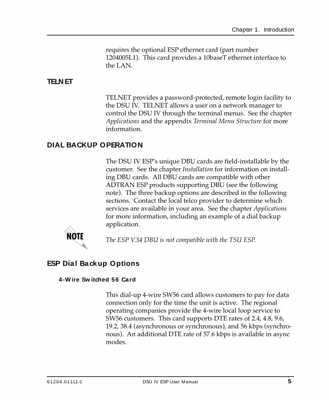
requires the optional ESP ethernet card (part number1204005L1). This card provides a 10baseT ethernet interface tothe LAN.
TELNET
TELNET provides a password-protected, remote login facility tothe DSU IV. TELNET allows a user on a network manager tocontrol the DSU IV through the terminal menus. See the chapterApplications and the appendix Terminal Menu Structure for moreinformation.
DIAL BACKUP OPERATION
The DSU IV ESP's unique DBU cards are field-installable by thecustomer. See the chapter Installation for information on install-ing DBU cards. All DBU cards are compatible with otherADTRAN ESP products supporting DBU (see the followingnote). The three backup options are described in the followingsections. Contact the local telco provider to determine whichservices are available in your area. See the chapter Applicationsfor more information, including an example of a dial backupapplication.
The ESP V.34 DBU is not compatible with the TSU ESP.
ESP Dial Backup Options
4-Wire Switched 56 Card
This dial-up 4-wire SW56 card allows customers to pay for dataconnection only for the time the unit is active. The regionaloperating companies provide the 4-wire local loop service toSW56 customers. This card supports DTE rates of 2.4, 4.8, 9.6,19.2, 38.4 (asynchronous or synchronous), and 56 kbps (synchro-nous). An additional DTE rate of 57.6 kbps is available in asyncmodes.

6 DSU IV ESP User Manual 61204.011L1-1
Chapter 1. Introduction
V.34 Card
The V.34 card has all of a V.32 bis modem's modes of operation,plus V.34 and V.FC modes. This allows the V.34 option to runsynchronous rates up to 33.6 kbps as opposed to the V.32 at 14.4kbps. In asynchronous mode the throughput at 57.6 kbps is lessdependent on data types.
ISDN Card
1B+D Basic Rate ISDN service provides the customer with aswitched 56/64 kbps circuit. In addition to 56 and 64 kbpssynchronous DTE rates, the card also supports synchronous andasynchronous DTE rates of 2.4, 4.8, 9.6, 19.2, and 38.4 kbps perCCITT V.120. The card also supports the DTE rate of 57.6 kbpsasync and is compatible with the 4-wire SW56 DBU card.
WARRANTY AND CUSTOMER SERVICE
ADTRAN will replace or repair this product within five yearsfrom the date of shipment if it does not meet its publishedspecifications or fails while in service. For detailed warranty,repair and return information refer to the ADTRAN EquipmentWarranty and Repair and Return Policy Procedure.
Return Material Authorization (RMA) is required prior toreturning equipment to ADTRAN.
For service, RMA requests, or further information, contact one ofthe numbers listed on the inside back cover of this manual.
61204.011L1-1 DSU IV ESP User Manual 7
Chapter 2. Installation
Chapter 2Installation
UNPACK, INSPECT, POWER UP
Receipt Inspection
Carefully inspect the DSU IV ESP for any shipping damage. Ifdamage is suspected, file a claim immediately with the carrierand contact ADTRAN Customer Service. If possible, keep theoriginal shipping container for use in shipping the DSU IV ESPfor repair or for verification of damage during shipment.
ADTRAN Shipments Include
The following items are included in ADTRAN shipments of theDSU IV ESP:
• DSU IV ESP unit• The user manual• An 8-position modular to 8-position modular cable• An 8-position modular to 8-position modular cable and a
modular to female DB-25 adapter for access to the Control/SLIP/PPP port

8 DSU IV ESP User Manual 61204.011L1-1
Chapter 2. Installation
The ADTRAN DSU IV ESP MIB is available from ADTRAN in thesupport section of the ADTRAN Web page at www.adtran.com.
The following items are included in ADTRAN shipments of ESPDBU cards:
• ESP DBU card• An 8-position modular to 8-position modular cable for the
4-wire SW56 and 1B+D ISDN dial backup options. An8-position modular to 4-position modular cable for the V.34backup option.
Customer Provides
The customer must provide either a male EIA-232 (standard 25-pin, D-type) or a male V.35 interface cable.
For SNMP management, the customer must provide access tothe DSU IV ESP either through a SLIP port, Async PPP port(requires a male 25-pin D-type connector), or a 10baseT ethernetport (requires that an ADTRAN ESP Ethernet card be installed inthe DSU IV ESP). See the appendix Pinouts for the pin assign-ments of the control port (for SLIP and Async PPP) and theethernet port.
Power Up
The DSU IV ESP is provided with a captive 8-foot power cord,terminated by a three-prong plug which connects to a grounded115 VAC power receptacle.
Power to the DSU must be provided from a grounded 115 VAC, 60 Hzreceptacle.
61204.011L1-1 DSU IV ESP User Manual 9
Chapter 2. Installation
REAR PANEL
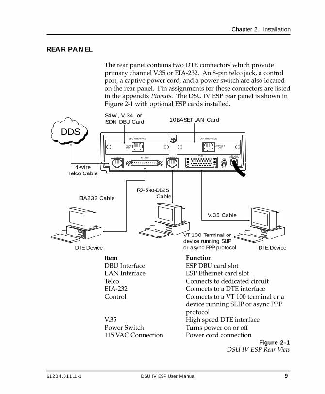
The rear panel contains two DTE connectors which provideprimary channel V.35 or EIA-232. An 8-pin telco jack, a controlport, a captive power cord, and a power switch are also locatedon the rear panel. Pin assignments for these connectors are listedin the appendix Pinouts. The DSU IV ESP rear panel is shown inFigure 2-1 with optional ESP cards installed.
DDS
VT 100 Terminal or device running SLIP or async PPP protocolDTE Device DTE Device
RJ45-to-DB25 Cable
V.35 Cable
TELCO EIA-232
DBU INTERFACE LAN INTERFACE
115 VAC60HZ.15A
ISDNDBU
10 BASE TLAN
ON
OFF
CONTROLV .35
S4W, V.34, or ISDN DBU Card 10BASET LAN Card
EIA232 Cable
4-wireTelco Cable
Item FunctionDBU Interface ESP DBU card slotLAN Interface ESP Ethernet card slotTelco Connects to dedicated circuitEIA-232 Connects to a DTE interfaceControl Connects to a VT 100 terminal or a
device running SLIP or async PPPprotocol
V.35 High speed DTE interfacePower Switch Turns power on or off115 VAC Connection Power cord connection
Figure 2-1DSU IV ESP Rear View
10 DSU IV ESP User Manual 61204.011L1-1
Chapter 2. Installation
DBU and Ethernet Card Slots
The DSU IV ESP rear panel has two card slots for the installationof dial backup and ethernet cards. To insert cards, perform thefollowing procedure:
1. Remove power from the DSU IV ESP.2. Slide the card into the corresponding rear slot until the card
panel is flush with the DSU IV chassis.3. Push card locks in (until they click) to secure the card and
ensure proper installation.
Card slots are keyed to prevent improper installation (i.e., putting aDBU card into the ethernet slot).
Remove power from the unit prior to installing or removing ESPoption cards.
Telco Connector: Network Interface Connection
The DSU IV ESP has an 8-position modular jack labeled TELCO.The telco connector is used for connecting to the DDS network.The pinout for this connector is listed in the appendix Pinouts.
Each ESP DBU card has a connector which is used for connectionto the switched backup network. The pinout for the connectordepends on the card type. Pinouts for 4-wire Switched 56, V.34,and ISDN 1B+D DBU options are shown in the appendixPinouts.
EIA-232 and V.35 Connectors: DTE Data Connection/Primary DTE
The primary DTE should be connected to either the EIA-232 DTEconnector or the V.35 DTE connector. The maximum cablelengths recommended are 50 feet for the EIA-232, and 100 feetfor the V.35. The pin assignments for the connectors are listed inthe appendix Pinouts.
61204.011L1-1 DSU IV ESP User Manual 11
Chapter 2. Installation
The V.35 connector is recommended for use with data ratesabove 19.2 kbps. The EIA-232 connector works up to 56 kbpswith a low capacitance cable or with the external transmit clockoption selected. The primary DTE rate is configured from thefront panel. The primary DTE equipment can operate in asyn-chronous or synchronous modes.
To prevent possible radio frequency interference emissions, a shieldedcable is required.
Control Port
The DSU IV has an 8-position modular jack labeled CONTROL.The control port provides connection to a VT 100 EIA-232compatible interface, a device running SLIP protocol, or a devicerunning Async PPP protocol. An 8-foot adapter connector andcable provide a standard DB-25 EIA-232 interface. See theappendix Pinouts for the control port’s pin assignments. Adescription of the operation of this port is covered in the Opera-tion chapter.
The control port also functions as the SLIP or Async PPP portwhen configured for SNMP management. The pinouts areidentical when operating in an SNMP management mode.

12 DSU IV ESP User Manual 61204.011L1-1
Chapter 2. Installation

61204.011L1-1 DSU IV ESP User Manual 13
Chapter 3. Operation
Chapter 3Operation
FRONT PANEL
The DSU IV ESP faceplate is shown in Figure 3-1. Descriptionsof each part of the front panel follow.
LCD WindowDisplays menu items and messages in 2 lines by 16 characters.
EnterSelects active menu items. To select a menu item, press thenumber of the item. The menu item flashes, indicating it isactivated. Press Enter to select the menu item.
KeypadThe keypad contains dual-function keys numbered 0 through 9with alpha characters A through F. These keys are used toactivate menu items and enter information.
ShiftEnter alpha characters by pressing and releasing Shift beforepressing the key representing the desired character. To activate amenu item designated by an alpha character rather than anumber press Shift and then the letter. The menu item flashes,indicating which parameter is activated. Press Enter to select theitem.
If a key is pressed without using Shift, the numbered itembecomes active instead of the alpha item.

14 DSU IV ESP User Manual 61204.011L1-1
Chapter 3. Operation
CancelPressing the Cancel key stops the current activity and returns tothe previous menu. Repeat until the desired menu level isreached. When a submenu item is displayed, press Cancel toexit the current display and return to the previous menu.
Up and Down ArrowsUp and Down Arrows scroll through the submenu items avail-able in the current menu.
LED DescriptionsThe DSU IV ESP has seven LED indicators: RS, CS, TD, RD, CD,ALM, and TST. These LEDs are identified as follows:
RS: Request to Send Reflects the status of the request to sendpin of the DTE interface.
CS: Clear to Send Reflects the status of the clear to sendpin of the DTE interface.
TD: Transmit Data This LED is active when data is trans-mitted from the DTE.
RD: Receive Data This LED is active when data is receivedfrom the network.
CD: Carrier Detect This LED is active when frame synchro-nization is achieved and the DSU IV ESPis ready to transfer data.
ALM: Alarm Indication This LED activates whenever an alarmcondition exists. Alarm conditionsinclude:• Open loop on network• No frame synchronization• Unit in dial backup• Problem on dial backup line
TST: Test Mode This LED is on whenever the unit is intest mode.

61204.011L1-1 DSU IV ESP User Manual 15
Chapter 3. Operation
SHIFT
*
7
D4
A1
8
0
E5
B2
QUICK
DSU IV ESP
#
9
F6
C3ENTER
CANCEL
Figure 3-1DSU IV ESP Front Panel
KeypadActivates menu items and
enters numeric information.
RD LEDActive when DTE port
receives data.
Enter KeySelects active menu item.
ALM LEDActive when
alarm conditionexists.
TST LEDActive when the unit is in
test mode.
CancelStops currentactivity and
returns to theprevious menu.
CD LEDActive when DSU receives acarrier signal from the line.
LCD WindowDisplays menu items andmessages in 2 lines by 16
characters.
ShiftActivates alpha selections.
RS LEDReflects status of
RTS pin of theprimary DTE
connector.
CS LEDReflects status of
CTS pin of theprimary DTE
connector.
TD LEDActive when DTE
port transmitsdata.
Up and Down ArrowsScroll through the
submenu items availablein the current menu.
Quick KeyReturns display toMain menu, Exit
Test screen, or DBUoptions menu.

16 DSU IV ESP User Manual 61204.011L1-1
Chapter 3. Operation

61204.011L1-1 DSU IV ESP User Manual 17
Chapter 3. Operation
Front Panel Menu Navigation
To choose a menu item, press the corresponding number oralpha character on the keypad. Press Shift to activate menuitems with alpha selections. The flashing menu item indicateswhich selection is activated. Press Enter to select the item. Thefollowing steps and Figure 3-2 illustrate how to select DSU IVESP options:
1. Activate Configuration (CONFIG) by pressing 3. Theactivated menu item will flash. Press Enter.
2. Select LOCAL or REMOTE configuration by pressing thecorresponding number, then press Enter.
3. Use the arrow keys to view submenu items.4. Choose an item on the submenu such as Network Options
(NETWORK OPT).5. Activate NETWORK OPT by pressing 1. Press Enter.6. Activate LOOP RATE options by pressing 1. Press Enter.7. Press the number corresponding to the desired loop rate.
Press Enter.
1=LOOP RATE1=LOCAL 1=NETWORK OPT. 2=NETWORK ADDR.
3=CONFIG 2=DTE OPTIONS 3=REMOTE CONFIG2=REMOTE 3=TEST OPTIONS 4=NETWORK TYPE
4=DIAL OPTIONS 5=CLOCK SOURCE5=MANAGEMENT6=UTILITIES
Figure 3-2Example of Basic Menu Navigation

18 DSU IV ESP User Manual 61204.011L1-1
Chapter 3. Operation
Front Panel Menu Structure
The DSU IV ESP uses a multilevel menu approach to access itsmany features. All menu operations are displayed in the LCDwindow or the terminal. See Figure 3-3 for the terminal Mainmenu.
The opening menu is the access point to all other operations.Each Main menu item has several functions and submenus toidentify and access specific parameters.
Front panel LCD display of the Main menu:
1=STATUS 2=TEST3=CONFIG 4=DIAL
The Dial selection in the Main menu is only available when a SW56network type is selected or when a DBU card is installed in the rear ofthe DSU IV ESP.
Main Menu
The branches of the front panel Main menu are divided intooptions for Status, Test, Configuration (CONFIG), and Dial.
StatusStatus menus display all relevant information for the networkand DTE interfaces. The system returns to the status displaywhen idle. For more information see the chapter Viewing StatusInformation.
TestUse Test menus to control local and remote testing. Select localor remote testing, and the type of test and test pattern whenrequired. For more information, see the chapter Testing andTroubleshooting.

61204.011L1-1 DSU IV ESP User Manual 19
Chapter 3. Operation
ConfigurationUse Configuration menus to select network and DTE operatingparameters, configure testing and dialing options, select man-agement functions, and configure unit utilities. This menubranch is divided into several chapters for easier reference. Thedivision includes a brief overview chapter followed by a sepa-rate chapter for each of the six submenus: Configuring NetworkOptions, Configuring DTE Options, Configuring Test Options,Configuring Dial Options, Configuring Management Functions, andConfiguring Unit Utilities.
DialDial provides manual dial backup or SW56 dial functions. Formore information, see the chapter Activating Dialing Functions.
20 DSU IV ESP User Manual 61204.011L1-1
Chapter 3. Operation
VT 100 TERMINAL CONNECTION AND OPERATION
To control the DSU IV ESP using a VT 100 terminal, perform thefollowing procedure:
1. Select a terminal interface through the front panel. Select 3CONFIG, 5 MANAGEMENT, 1 INTERFACE, 1 TERMCONTROL.
2. Set the CONTROL RATE to match the VT 100 terminal.
3. Using the provided VT 100 terminal adapter cable, connectthe COM port of a VT 100 compatible terminal or equivalentto the eight-pin modular jack labeled CONTROL on the rearof the DSU IV ESP. This connection is used for both localand remote configuration.
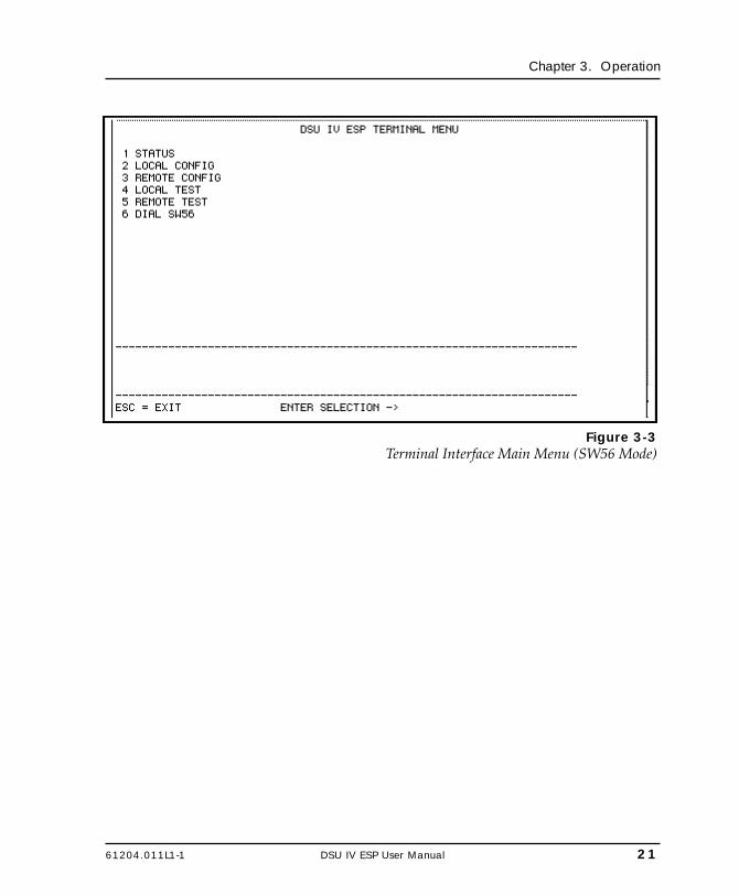
4. Establish the connection and press Enter repeatedly until theTerminal Menu appears (Figure 3-3).
5. Make selections by entering the number corresponding tothe chosen parameter. Press ESC to return to the previousscreen.
Due to the increased display capabilities, the VT 100 menu structurediffers from the front panel interface. The appendix Terminal MenuStructure includes the VT 100 screens as well as a complete menu treefor accessing configuration selections. Descriptions of individual menuoptions are provided throughout this manual based on the front panelmenu structure. See Figure 5-1 for the front panel configuration menutree.
When establishing a TELNET session, the system prompts for apassword. The default password is adtran. This password can bemodified through the Management menu. See the chapter ConfiguringManagement Functions for more information.
61204.011L1-1 DSU IV ESP User Manual 21
Chapter 3. Operation
Figure 3-3Terminal Interface Main Menu (SW56 Mode)

22 DSU IV ESP User Manual 61204.011L1-1
Chapter 3. Operation

61204.011L1-1 DSU IV ESP User Manual 23
Chapter 4. Applications
Chapter 4Applications
This chapter provides examples of some common DSU IV ESPapplications. The examples include LAN applications with bothSLIP/PPP and ethernet management and a dial backup applica-tion.
LAN APPLICATION WITH SNMP/TELNET MANAGEMENT
The DSU IV can be managed through an established TELNETsession or an SNMP-based network manager like HPOpenview®, IBM Netview®, or SunNet Manager®.
The ADTRAN DSU IV ESP MIB is available in the support section ofthe ADTRAN Web page at www.adtran.com.
SNMP and TELNET management are provided by one of thefollowing interfaces:
• A device (i.e., a router) running SLIP protocol. Connection ismade through the DSU IV's control port. See Figure 4-1.
• A device (i.e., a router) running async PPP protocol. Connec-tion is made through the DSU IV's control port. See Figure 4-1.
• A LAN. Connection is made through the optional 10baseTethernet interface provided on the ESP ethernet card (partnumber 1204005L1). See Figure 4-2.

24 DSU IV ESP User Manual 61204.011L1-1
Chapter 4. Applications
Router
SLIP/PPP
DSU IV ESP
DSU IV ESP
SNMPManagment Station
SLIP/PPP
EIA 232 or V.35
EIA 232 or V.35
Router
LANLAN
DDS orFrame Relay DSU IV ESP
RD1 TD2 RD2 TDN RDN
TD1
ALM/TST
1A
CB
4D
FE
SHIFTDELETE QUICK
NEXTPREV
ADD7
2
5
#
3
6
98
0DSU IV ESP
RD1 TD2 RD2 TDN RDN
TD1
ALM/TST
1A
CB
4D
FE
SHIFTDELETE QUICK
NEXTPREV
ADD7
2
5
#
3
6
98
0
Figure 4-1SLIP/PPP LAN Application with SNMP/TELNET Management
Router
Ethernet
DSU IV ESP
DSU IV ESP
SNMPManagement Station
Ethernet
EIA 232 or V.35
EIA 232 or V.35
Router
LANLAN
DDS orFrame Relay DSU IV ESP
RD1 TD2 RD2 TDN RDN
TD1
ALM/TST
1A
CB
4D
FE
SHIFTDELETE QUICK
NEXTPREV
ADD7
2
5
#
3
6
98
0DSU IV ESP
RD1 TD2 RD2 TDN RDN
TD1
ALM/TST
1A
CB
4D
FE
SHIFTDELETE QUICK
NEXTPREV
ADD7
2
5
#
3
6
98
0
Figure 4-2Ethernet LAN Application with SNMP/TELNET Management

61204.011L1-1 DSU IV ESP User Manual 25
Chapter 4. Applications
Minimum Configuration Requirements for SNMP/TELNET Access
The following options are the minimum configuration require-ments for establishing SNMP or TELNET access. Once theseoptions are configured, the remaining options may be configuredusing SNMP/TELNET. See the menu tree in Figure 10-1 in thechapter Configuring Management Functions for the front panelmenu path to these options.
InterfaceSelect SLIP Control, PPP Control, or Ethernet LAN as the DSU IVinterface type. The ESP ethernet card must be installed for theEthernet LAN selection.
IP AddressEnter the DSU IV ESP IP address.
Subnet MaskEnter the subnet number. This address is available from thenetwork administrator.
Gateway IP Address (if required)Enter the Gateway node IP address. This address is necessaryonly if the DSU IV and the network manager are connectedthrough a Gateway node. This address is available from thenetwork administrator.
Special Features of this Application
Customize the SNMP/TELNET application using the followingDSU IV ESP features:• Designate SNMP hosts to receive SNMP traps from the DSU IV
(one to five entries).• Secure the DSU IV by limiting SNMP network management
access. If enabled, the DSU IV only responds to a user-config-ured list of SNMP network managers (one to five entries).
Configure these options through the Management portion of theConfiguration menu. See the chapter Configuring ManagementFunctions for more information.

26 DSU IV ESP User Manual 61204.011L1-1
Chapter 4. Applications
DIAL BACKUP APPLICATION
The DSU IV provides point-to-point connection to the network.With one of the ESP DBU option cards installed, the unit iscapable of dial backup, allowing the unit to dial around a failednetwork. See Figure 4-3.
With the DBU options, configure the unit to:• Enter DBU under specific primary network conditions.• Lock out DBU over the weekend and/or at specified times of
the day.• Dial a specified number when a DBU activation condition is
detected.
DSU IV ESP
DSU IV ESP
DDS
SwitchedNetwork
V.34, ISDN, 4-Wire
Switched 56
DSU IV ESP
RD1 TD2 RD2 TDN RDN
TD1
ALM/TST
1A
CB
4D
FE
SHIFTDELETE QUICK
NEXTPREV
ADD7
2
5
#
3
6
98
0
DSU IV ESP
RD1 TD2 RD2 TDN RDN
TD1
ALM/TST
1A
CB
4D
FE
SHIFTDELETE QUICK
NEXTPREV
ADD7
2
5
#
3
6
98
0
DTE Device
DTE Device
Figure 4-3Dial Backup Application
Entering Dial Backup Mode
When a condition for entering dial backup mode is detected, theAlarm LED turns on and the buzzer sounds. The buzzer alter-nates between 30 seconds on and 30 seconds off unless the DDSline is restored or it is disabled by using the Quick key andselecting Turn Off Beep. See the section Front Panel in thechapter Operation for more information on the Quick key.
61204.011L1-1 DSU IV ESP User Manual 27
Chapter 4. Applications
Operation During Critical Times
The following four conditions will cause a DSU IV ESP to enterdial backup mode:
Loss of Sealing CurrentSealing current is a low voltage DC current provided by thecentral office (CO) to prevent corrosion over the copper wiresused in the local loop. Sealing current may also be used for localloop testing purposes. An absence of sealing current generally isan indication that the loop is open.
Out of Service (OOS) SignalAn OOS signal, generated by the network, indicates a device (ordevices) in the network is out of service.
No Receive SignalThis is an indication that the local loop copper pairs may beeither open or shorted or the OCU in the CO is inoperative. In aprivate network this may indicate that the transmitter of theremote DSU is inoperative.
All 1s or all 0s ConditionThis condition is usually generated by the network to indicatesome device (or devices) in the network is inoperative. Upondetecting an all 1s or all 0s condition, the DSU IV ESP initiates ahandshake routine to determine whether the remote unit's DTEis the source of the all 1s or 0s condition or if an actual networkfailure exists.
Answer AlwaysWhen this option is enabled, the unit goes into DBU mode if acall is present regardless of the status of the dedicated circuit. Itis recommended that the DBU Passcode be used in this modesince inadvertent calls could stop data flow indefinitely.
The DBU Answer Test is disabled if this option is chosen.
28 DSU IV ESP User Manual 61204.011L1-1
Chapter 4. Applications
Operation During Noncritical Times
The DSU IV ESP may be configured not to enter dial backupmode if data terminal ready (DTR) is low. This feature preventsthe DSU IV ESP from entering dial backup during noncriticaltimes such as nights and weekends.
For more information, see the chapter Configuring Dial Options.
Weekend and Time of Day LockoutThe DSU IV ESP may be configured not to enter dial backupmode based upon the time of day or weekend status. Thisprotects the customer from being charged for a switched callduring off hours should the dedicated circuit fail. See thechapter Configuring Dial Options for more information.
Conditions for Returning to the DDS Circuit
The DSU IV ESP can be configured to automatically revert to theDDS circuit from the dial backup mode or wait to be returned tothe DDS manually. Once the DSU IV ESP enters dial backupmode, the unit polls the DDS circuit once every 100 ms todetermine if the condition causing the DDS circuit failure hasbeen corrected. Once the DSU IV ESP determines that theproblem has been properly corrected and the DDS circuit isstable, it will wait for the amount of time specified in the restoretimer (1 - 255 minutes) before reverting to the DDS circuit.Polling of the DDS circuit is non-intrusive and return to the DDScircuit generally takes 2 - 3 seconds. The backup connection ismaintained for one minute after the DDS circuit is restored.
See the chapter Configuring Dial Options for more detailedinformation.

61204.011L1-1 DSU IV ESP User Manual 29
Chapter 5. Configuration Overview
Chapter 5Configuration Overview
The DSU IV ESP contains four different user profiles (sets ofconfiguration options) stored in read only memory; see theappendix Configuration Profiles. The unit is shipped from thefactory with profile number 1 (default configuration) loaded intothe current (nonvolatile configuration) memory. If profile 1matches requirements for the system, then no additional con-figuration is required to put the unit into service. If profile 1does not match system requirements, it can be modified or oneof the other profiles that more closely matches the systemrequirements can be loaded into current memory. When adifferent profile is loaded or the existing profile is modified, it isstored in the current (nonvolatile configuration) memory. TheDSU IV ESP is then configured with that profile every timepower is turned on or the unit is reset.
CONFIGURATION METHODS
The DSU IV ESP responds to the following methods of configu-ration:• AT commands• V.25 commands• Front panel commands• A VT 100 compatible terminal• SNMP/TELNET through a device running SLIP/PPP protocol• SNMP/TELNET through a LAN running ethernet protocol
(available when the optional ESP Ethernet card is installed)

30 DSU IV ESP User Manual 61204.011L1-1
Chapter 5. Configuration Overview
AT and V.25 commands have limited access to configurationparameters. The commands are detailed in the followingsections of this chapter. See the chapters Installation and Opera-tion for more information on all other configuration methods.For an example application using the SLIP/PPP or ethernetinterface, see the chapter Applications.
Descriptions of each Configuration menu item are given in thefollowing chapters: Configuring Network Options, ConfiguringDTE Options, Configuring Test Options, Configuring Dial Options,Configuring Management Functions, and Configuring Unit Utilities.
A complete Configuration menu for the front panel is shown inFigure 5-1. The VT 100 menu tree is shown in the appendixTerminal Menu Structure.
Due to the increased display capabilities, the VT 100 menu structurediffers from the front panel interface. The appendix Terminal MenuStructure includes the VT 100 screens as well as a complete menu treefor accessing configuration selections. Descriptions of individual menuoptions are provided throughout this manual based on the front panelmenu structure. See Figure 5-1 for the front panel configuration menutree.

61204.011L1-1 DSU IV ESP User Manual 31
Chapter 5. Configuration Overview
Figure 5-1Front Panel Configuration Menu Tree
1=2.4K2=4.8K
1=AUTO 3=9.6K1=LOOP RATE 2=2.4K 4=19.2K
3=4.8K 5=38.4K1=NETWORK OPT. 4=9.6K 1=DTE RATE 6=56K/57.6K 1=SCRAMBLER OFF
5=19.2K 7=SAME AS LOOP 2=SCRAMBLER ON6=38.4K 3=SUPPRESS LBE7=56K 1=EIA 2328=64K 2=CONNECTOR TYPE 2=V.35
3=DATA FORMAT 1=ASYNCHRONOUS 1=ASYNC 9 BITS2=NETWORK ADDR. ENTER NETWORK 2=SYNCHRONOUS 2=ASYNC 10 BITS
ADDRESS:00 3=ASYNC 11 BITS1=DISABLED
3=REMOTE CONFIG. 1=DISABLED 4=DTE CMD OPTION 2=AT COMMAND SET2=ENABLED 3=V.25 SYNC
4=V.25 BSC/ASYNC4=NETWORK TYPE 1=DEDICATED
2=AT&T/MCI SW56 5=TRANSMIT CLOCK 1=NORMAL3=US SPRINT SW56 2=EXTERNAL 1=FORCED ON
3=INVERT 2=FOLLOWS RS 1=CS DELAY SHORT6=CS OPTIONS 3=FOLLOWS CD 2=CS DELAY LONG
5=CLOCK SOURCE 1=MASTER2=FROM NETWORK 7=ANTI-STREAM 1=TIMER OFF 4=FOLLOWS RS+CD 1=CS DELAY SHORT
2=DTE OPTIONS 2=TIME 10 SEC. 5=OFF WITH LOCD 2=CS DELAY LONG3=TIME 30 SEC.
ENTER TIMEOUT 4=TIME 60 SEC. 1=FORCED ON1=TEST TIMEOUT (0=OFF) : 00 SEC 8=CD OPTIONS 2=NORMAL
3=OFF WITH LOCD2=RDL EN/DIS 1=RDL IGNORED
1=LOCAL 2=RDL ACCEPTED 9=TR OPTIONS These selections are dependent upon the operation mode (SW56 or DBU). See the chapter Configuring DTE Options for more information.
3=EIA LLB EN/DIS 1=DISABLED3=CONFIG 3=TEST OPTIONS 2=ENABLED A=SR OPTIONS 1=FORCED ON
2=OFF OOS ONLY2=REMOTE ENTER ADDRESS 4=EIA RLB EN/DIS 1=DISABLED 3=OFF LOCD ONLY
2=ENABLED 4=OFF TEST ONLY5=OFF TEST + OOS
5=DBU ANS. TEST 1=DISABLED 6=OFF TEST + LOCD STORED NUMBER TO2=ENABLED 1=PHONE NUMBERS EDIT (1-10): NNNNNNN
4=DIAL OPTIONS 2=SW56 AUTO ANS 1=DISABLED2=ENABLED
1=INTERFACE 1=VT100 CONTROL 3=DBU OPTIONS These selections are dependent upon the DBU card. 2=SLIP CONTROL See the chapter Configuring Dial Options for this portion of the menu tree.
5=MANAGEMENT 3=PPP CONTROL4=ETHERNET LAN 4=DBU PASSCODE 1=ENABLE/DISABLE 1=DISABLE
6=UTILITIES 1=MANUAL COMMAND COMMAND: 00 COMMAND: HH 2=ENABLEVALUE:00 1=1200 BPS
2=2400 BPS 2=ENTER CODE XXXX2=TIME/DATE 1=CURRENT TIME=23:01:59 2=CONTROL RATE 3=9600 BPS
DATE=08/15/971=UNIT IP ADR
2=SET TIME 1=SET HOURS ENTER CURRENT 3=IP OPTIONS 2=SUBNET MASKHOUR (HH):01 3=GATEWAY IP ADR 1=DISABLED
4=IP SECURITY 2=ENABLED2=SET MINUTES ENTER CURRENT
MIN. (MM):01 1=GET COMMUNITY 5=IP FILTER ADDR ENTER SOURCE IP2=SET COMMUNITY NUMBER (1-5):1
3=SET SECONDS ENTER CURRENT 4=SNMP OPTIONS 3=TRAP COMMUNITY 1=DISABLESEC. (SS):01 4=SNMP TRAPS 2=GENERIC ONLY
3=ENABLE ALL3=SET DATE 1=SET MONTH ENTER CURRENT 5=TRAP IP ADR ENTER TRAP IP
MONTH (MM):01 6=SYS NAME NUMBER (1-5):17=SYS CONTACT
2=SET DAY ENTER CURRENT 8=SYS LOCATION 1=DISABLEDDAY (DD):07 9=AUTHEN TRAP 2=ENABLED
3=SET YEAR ENTER CURRENT 1=TELN PASSWORDYEAR (YY):97 5=TELNET OPTIONS 1=10 MINUTES
VERSION CHKSUM 2=TELNET TIMEOUT 2=30 MINUTES3=SOFTWARE REV. REV X XXXX 3=60 MINUTES
4=LAN MAC ADDR.
5=SERIAL NUMBER xxxxxxxxxxxxxxx

32 DSU IV ESP User Manual 61204.011L1-1
Chapter 5. Configuration Overview
61204.011L1-1 DSU IV ESP User Manual 33
Chapter 5. Configuration Overview
AT Commands
The DSU IV ESP can be configured and controlled with in-bandAT commands from an asynchronous DTE port just as modemsare.
To exit the data mode and enter the command mode, the asyn-chronous DTE device must transmit a proper escape sequence ofthree pluses (+++) to the DSU IV ESP. A specified time delaymust occur between the last data character and the first escapesequence character. This is the guard time delay, and it can bechanged by writing a value to the S12 register. The default valuefor the guard time is one second. For a valid escape sequence tooccur, the DTE must transmit the escape code character threetimes in succession with delay between each character being lessthan the guard time.
Once the command mode is entered, AT commands can betransmitted to the DSU IV ESP to configure most of the optionsor initiate tests to check both the DSU IV ESP and the networkconnections. All command lines must begin with the AT charac-ter set in either capital or lower case letters.
The command line may contain a single command or a series ofcommands after the AT attention code. When a series of com-mands is used, the individual commands may be separated withspaces for readability. The maximum length for a command lineis 40 characters. Each command line is executed by the DSU IVESP upon receipt of a terminating character. The default termi-nating character is a carriage return (ASCII 013), but it can bechanged by writing a different value to register S3.
Before the terminating character is transmitted, the commandline can be edited by using the backspace character (ASCII 008)to erase errors so the proper commands can be entered.
Not all parameters can be selected using these commands. Validcommands are listed in the appendix AT Commands.

34 DSU IV ESP User Manual 61204.011L1-1
Chapter 5. Configuration Overview
V.25 bis Commands
When configured for the V.25 bis option, the DSU IV ESP acceptsin-band dialing and configuration commands from both syn-chronous and asynchronous DTE ports.
The V.25 bis option supports the following protocols:
• SDLC• Bi-Sync• Asynchronous
SDLC Option
Character Format• Data bits - 8• Parity bit - Ignored
Command Structure[F][A][C][V.25 bis COMMAND][FCS][F]
The address field [A] is FFH. The control field [C] is set to 13Hexcept for cases of multi-frame responses. For this case, thecontrol field is set to 03H in all but the last frame. The 03H in thecontrol field indicates that other frames are to follow while the13H in the control field indicates the final frame.
Bi-Sync Option
Character Format• Data bits - 7• Parity bit - Odd
Command Structure[SYN][SYN][STX][V.25 bis COMMAND][ETX]
61204.011L1-1 DSU IV ESP User Manual 35
Chapter 5. Configuration Overview
Asynchronous Option
Character Format• Start bit - 1• Data bits - 7• Parity bit - Even• Stop bit - 1
Command Structure[V.25 bis COMMAND][CR][LF]
Command Descriptions
The ADTRAN V.25 bis command set is a subset of the CCITTV.25 bis command set. In addition to the CCITT commandssupported, ADTRAN has added configuration commands forboth local and remote DSUs. The ADTRAN V.25 bis commandset follows:
CNL Configuration localCNR Configuration remote
Possible responses to V.25 bis commands follows:
VALA Valid V.25 command processedINV An invalid command detectedINVCU Unknown command detectedINVPS Invalid parameter syntaxINVPV Invalid parameter valueINVBL Invalid local passwordINVBM Invalid remote password
If verbose responses are disabled (ATV0), the following three-character responses are the only ones returned:
VAL Valid V.25 command processedINV Invalid command received

36 DSU IV ESP User Manual 61204.011L1-1
Chapter 5. Configuration Overview
Syntax and Possible Responses
CNL (Configuration Local)This command is used to pass AT commands to the local DSUvia the V.25 bis command processor. This allows the DSU IV ESPto be configured with AT commands using a synchronousinterface. The format is as follows:
CNL[LOCAL PASSWORD];AT[ONE OR MORE AT COMMANDS]
A local password may not be required depending on the presentconfiguration of the unit. Responses to CNL commands arereturned in the data format currently configured. Possibleresponses include: VALA and INVAn.
CNR (Configuration Remote)This command is used to pass AT commands over the networkto the remote DSU via the V.25 bis command processor. Thisallows a remote DSU IV ESP to be configured from a synchro-nous interface. The format of this command follows:
CNR[REMOTE PASSWORD];AT[ONE OR MORE AT COMMANDS]
The remote password may or may not be required depending onthe present configuration of the remote unit. Responses to theCNR commands are returned in the data format currentlyconfigured. Possible responses include: VAL and INVAn.

61204.011L1-1 DSU IV ESP User Manual 37
Chapter 6. Configuring Network Options
Chapter 6Configuring Network Options
NETWORK OPTIONS
The Network Options configuration parameters control the loopoperation of the DSU IV ESP. Once a parameter is set, Com-mand Accepted is displayed briefly before returning to theactive menu. Table 6-A shows the AT commands used to set theNetwork Options. See Figure 6-1 for the Network Options menutree.

38 DSU IV ESP User Manual 61204.011L1-1
Chapter 6. Configuring Network Options
Table 6-ANetwork Options AT Commands
Front Panel AT Command
Loop RateAUTO %B02.4K %B14.8K %B29.6K %B319.2K %B438.4K %B556K %B664K %B7Network AddressXX (decimal) _N=xxRemote Configuration1=DISABLED &P42=ENABLED &P5Network Type1=DEDICATED none2=AT&T/MCI SW56 none3=US SPRINT SW56 noneClock Source1=MASTER _X02=FROM NETWORK _X1

61204.011L1-1 DSU IV ESP User Manual 39
Chapter 6. Configuring Network Options
1=AUTO1=LOOP RATE 2=2.4K
3=4.8K1=NETWORK OPT. 4=9.6K
1=LOCAL 5=19.2K2=DTE OPTIONS 6=38.4K
3=CONFIG 3=TEST OPTIONS 7=56K2=REMOTE ENTER ADDRESS 4=DIAL OPTIONS 8=64K
5=MANAGEMENT6=UTILITIES
2=NETWORK ADDR. ENTER NETWORKADDRESS:00
3=REMOTE CONFIG. 1=DISABLED2=ENABLED
4=NETWORK TYPE 1=DEDICATED2=AT&T/MCI SW563=US SPRINT SW56
5=CLOCK SOURCE 1=MASTER2=FROM NETWORK
Figure 6-1Network Options Menu Tree
Loop Rate
The Loop Rate option sets the loop operating speed. The unitshould be set to the rate required by the DDS Service. The DSUIV ESP also supports subrate DTE data over a 56 or 64 kbps loop.The loop rate must be set independently of the DTE rate. Eightloop rate selections are available (shown in Figure 6-1).
The default factory setting is Auto. The various loop rates andformat selections are listed in Table 6-A with the equivalent ATcommands that perform the same configuration functions.
40 DSU IV ESP User Manual 61204.011L1-1
Chapter 6. Configuring Network Options
Network Address
A two-digit decimal address can be assigned to each DSU IVESP. This addressing capability makes it possible to performremote configuration and testing in point-to-point and multi-drop networks. Figure 6-1 shows the menu path used to changethe network address. The factory default setting is 0.
Remote Configuration
This option sets up the DSU IV ESP to accept or reject remoteconfiguration commands. The factory default setting isEnabled.
Network Type
Select the appropriate network type. The choices are dedicated,AT&T/MCI SW56, and US Sprint SW56.
Clock Source
The Clock Source option specifies the timing source for the DSUIV ESP’s internal circuitry. The factory default setting is FromNetwork.
When operating on a DDS network, the timing should be FromNetwork. On a point-to-point private network, one DSU IV ESPmust be set for Master, the other set for From Network.
61204.011L1-1 DSU IV ESP User Manual 41
Chapter 7. Configuring DTE Options
Chapter 7Configuring DTE Options
DTE OPTIONS
The DTE Options menu is used to select the configurationparameters that control the operation of the DTE Interface of theDSU IV ESP. The DTE Options menu tree is shown in Figure 7-1.Table 7-A shows the available options and their AT commands.
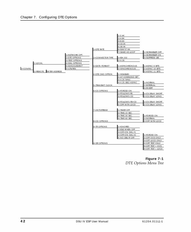
42 DSU IV ESP User Manual 61204.011L1-1
Chapter 7. Configuring DTE Options
1=2.4K2=4.8K3=9.6K4=19.2K5=38.4K
1=DTE RATE 6=56K/57.6K7=SAME AS LOOP 1=SCRAMBLER OFF
1=NETWORK OPT. 2=SCRAMBLER ON2=DTE OPTIONS 2=CONNECTOR TYPE 1=EIA 232 3=SUPPRESS LBE3=TEST OPTIONS 2=V.35
1=LOCAL 4=DIAL OPTIONS5=MANAGEMENT 3=DATA FORMAT 1=ASYNCHRONOUS 1=ASYNC 9 BITS
3=CONFIG 6=UTILITIES 2=SYNCHRONOUS 2=ASYNC 10 BITS2=REMOTE ENTER ADDRESS 3=ASYNC 11 BITS
4=DTE CMD OPTION 1=DISABLED2=AT COMMAND SET3=V.25 SYNC4=V.25 BSC/ASYNC 1=NORMAL
5=TRANSMIT CLOCK 2=EXTERNAL3=INVERT
6=CS OPTIONS 1=FORCED ON2=FOLLOWS RS 1=CS DELAY SHORT3=FOLLOWS CD 2=CS DELAY LONG
4=FOLLOWS RS+CD 1=CS DELAY SHORT5=OFF WITH LOCD 2=CS DELAY LONG
7=ANTI-STREAM 1=TIMER OFF2=TIME 10 SEC.3=TIME 30 SEC. 1=FORCED ON4=TIME 60 SEC. 2=NORMAL
8=CD OPTIONS 3=OFF WITH LOCD
9=TR OPTIONS 1=IGNORED2=IDLE WHEN OFF3=OFF>ON DIAL #14=OFF>ON DIAL #2 1=FORCED ON5=NO DBU IF OFF 2=OFF OOS ONLY
3=OFF LOCD ONLYA=SR OPTIONS 4=OFF TEST ONLY
5=OFF TEST + OOS6=OFF TEST + LOCD
Figure 7-1DTE Options Menu Tree

61204.011L1-1 DSU IV ESP User Manual 43
Chapter 7. Configuring DTE Options
Table 7-ADTE Options AT Commands
FrontPanel
ATCommand Description
DTE Rate1=2.4K %K3 DTE rate: 2.4K sync and async2=4.8K %K4 DTE rate: 4.8K sync and async3=9.6K %K5 DTE rate: 9.6K sync and async4=19.2K %K6 DTE rate: 19.2K sync and async5=38.4K %K7 DTE rate: 38.4K sync and async6=56K/57.6K %K8 DTE rate: 56K sync or 57.6K async7=SAME AS LOOP %K9 DTE rate matches loop rate1=SCRAMBLER OFF _F0 DTE data scrambler disabled (64 kbps
loop rate only)2=SCRAMBLER ON _F1 DTE data scrambler enabled (64 kbps
loop rate only)3=SUPPRESS LBE _F2 Suppresses loopback enable code
(LBE) in transmit data from the DTE after 30 bytes in a row detected (64 kbps loop rate only)
Data Format
1=ASYNCHRONOUS &Q0 Asynchronous DTE operation mode2=SYNCHRONOUS &Q2 Synchronous DTE operation modeDTE CMD Option1=DISABLED none Disables all DTE command modes2=AT COMMAND SET none Enables AT command mode for DTE3=V.25 SYNC none Enables V.25 (SDLC) command mode
for DTE
4=V.25 BSC/ASYNC none Enables V.25 (bisync or async) command mode for DTE
Transmit Clock
1=NORMAL &X0 TX clock from DSU selected2=EXTERNAL &X1 ETC clock from DTE selected3=INVERT &X3 Inverted Tx clock from DSU selected

44 DSU IV ESP User Manual 61204.011L1-1
Chapter 7. Configuring DTE Options
Table 7-A (Continued)DTE Options AT Commands
FrontPanel
ATCommand Description
CS Options1=FORCED ON &R0 CS always on2=FOLLOWS RS &R1 CS state same as RS state3=FOLLOWS CD &R2 CS state same as CD state4=FOLLOWS RS+CD &R3 CS state same as RS and CD state5=OFF WITH LOCD &R4 Off 5 sec after LOCD (SW56 only)
For Follows RS options, select the length of the delay.1=CS DELAY SHORT _D0 Short delay from RS to CS selected2=CS DELAY LONG _D1 Long delay from RS to CS selected
Anti-Stream1=TIMER OFF %T0 Anti-stream timer disabled2=TIME 10 SEC. %T1 Timeout equals 10 seconds3=TIME 30 SEC. %T2 Timeout equals 30 seconds4=TIME 60 SEC. %T3 Timeout equals 60 seconds
CD Options1=FORCED ON &C0 On all the time2=NORMAL &C1 On only when data present on loop3=OFF WITH LOCD &C2 On except after disconnect (SW56
only)
TR Options
1=IGNORED &D0 Ignore the TR input2=IDLE WHEN OFF &D2 See the following note.3=OFF>ON DIAL #1 &D3 Dial Stored #1: TR goes off to on
(SW56 only)
4=OFF >ON DIAL #2 &D4 Dial Stored #2: TR goes off to on (SW56 only)
5=NO DBU IF OFF (valid only when DBU ESP card is installed and Network Type is set to DEDICATED)
&D3 No dial backup if TR is off.
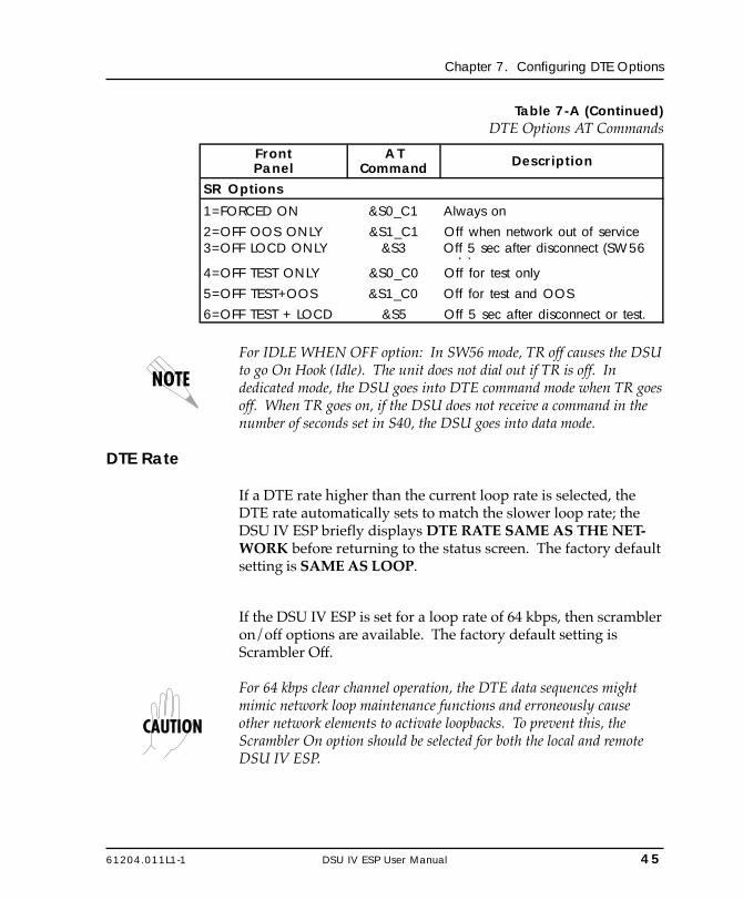
61204.011L1-1 DSU IV ESP User Manual 45
Chapter 7. Configuring DTE Options
Table 7-A (Continued)DTE Options AT Commands
FrontPanel
ATCommand Description
SR Options
1=FORCED ON &S0_C1 Always on2=OFF OOS ONLY &S1_C1 Off when network out of service3=OFF LOCD ONLY &S3 Off 5 sec after disconnect (SW56
l )4=OFF TEST ONLY &S0_C0 Off for test only5=OFF TEST+OOS &S1_C0 Off for test and OOS6=OFF TEST + LOCD &S5 Off 5 sec after disconnect or test.
For IDLE WHEN OFF option: In SW56 mode, TR off causes the DSUto go On Hook (Idle). The unit does not dial out if TR is off. Indedicated mode, the DSU goes into DTE command mode when TR goesoff. When TR goes on, if the DSU does not receive a command in thenumber of seconds set in S40, the DSU goes into data mode.
DTE Rate
If a DTE rate higher than the current loop rate is selected, theDTE rate automatically sets to match the slower loop rate; theDSU IV ESP briefly displays DTE RATE SAME AS THE NET-WORK before returning to the status screen. The factory defaultsetting is SAME AS LOOP.
If the DSU IV ESP is set for a loop rate of 64 kbps, then scrambleron/off options are available. The factory default setting isScrambler Off.
For 64 kbps clear channel operation, the DTE data sequences mightmimic network loop maintenance functions and erroneously causeother network elements to activate loopbacks. To prevent this, theScrambler On option should be selected for both the local and remoteDSU IV ESP.
46 DSU IV ESP User Manual 61204.011L1-1
Chapter 7. Configuring DTE Options
Connector Type
The Connector Type option is used to specify which of theprimary channel connectors is used to connect to the DTE. Thefactory default setting is V.35. There are no AT commandsavailable to set the connector type.
Data Format
The Data Format option is used to select either the synchronousor asynchronous mode of operation for the DTE interface. Thefactory default setting is Synchronous. If asynchronous ischosen, the length of the data bytes must be selected.
Table 7-A shows the AT commands that can be used to set theData Format to asynchronous or synchronous.
DTE Command Option
The DTE Command option is used to enable a DTE commandmode or disable all modes. The available modes are AT , V.25synchronous, and V.25 bisynchronous/asynchronous com-mands.
Transmit Clock
The Transmit clock option is used to select the source of the clockused to transfer data from the DTE into the DSU IV ESP.Table 7-A shows the AT commands used to set the TransmitClock options.
The External clock option is normally used in modem tail circuitapplications. A DSU to modem interconnect diagram for thisapplication is shown in the appendix DSU to Modem Interconnect.The External clock option is also recommended when theEIA-232 connector is used for 56 kbps and 64 kbps applications.Using this option eliminates data errors caused by excessivedelays in the DTE transmit clock receiver and transmit datadriver.

61204.011L1-1 DSU IV ESP User Manual 47
Chapter 7. Configuring DTE Options
The Invert clock option is recommended when the EIA-232connector is used for rates other than 56 kbps or 64 kbps.
Clear to Send (CS) Options
The CS Options menu is used to select the control mode for theCS lead. The default factory setting is Follows RS with CS DelayShort.
If one of the options chosen involves request to send (RS), thenthe delay from RS to CS must be selected. Table 7-A shows theAT Commands used to set the CS options.
Specified times for the short and long delays at the differentoperating speeds are shown in Table 7-B.
Table 7-BShort and Long Delays at Different Operating Speeds
Rate Short Delay Long Delay
64 1.1ms 16.1ms56 1.1ms 16.1ms
19.2 1.5ms 16.5ms4.8 1.5ms 16.5ms2.4 1.5ms 16.5ms
Anti-Stream
The Anti-Stream option is used to select the anti-stream timeout.The anti-stream timeout is the maximum time the DSU IV ESPtransmits data into the network from the DTE. This featureprevents one DTE device on a multi-drop network from continu-ously tying up the transmit circuit back to the master DSU.
The anti-stream timer is reset to zero when RS changes to theactive state and is updated every second while RS is active.When the anti-stream timeout expires, the DSU IV ESP stopstransmitting DTE data into the network but continues to acceptdata from it. This condition exists until the DTE deactivates theRS input.
48 DSU IV ESP User Manual 61204.011L1-1
Chapter 7. Configuring DTE Options
The factory default setting is Timer Off. Table 7-A shows theavailable options and their AT commands.
CD Options
The CD Options menu is used to select the control mode for thereceive line signal detector (CD) lead. The default factory settingis Normal. Table 7-A shows the equivalent AT commands forsetting CD options.
Data Terminal Ready (TR) Options
The TR Options menu is used to select the DSU IV ESP responseto the data terminal ready (TR) lead. The factory default settingis Ignored. Table 7-A shows the equivalent AT commands forsetting TR options.
The NO DBU IF OFF selection is available only when a DBU ESPcard is installed and the Network Type is set to DEDICATED.
To disable DBU when DTR is off, set this option for IDLE WHENOFF.
Data Set Ready (SR) Options
The SR Options menu is used to select the operating mode forthe data set ready (SR) lead. Use Shift + A to activate the SROptions submenu; press Enter to enter the SR Options submenu.The factory default setting is Off Test Only. Table 7-A shows theAT commands for setting SR options.

61204.011L1-1 DSU IV ESP User Manual 49
Chapter 8. Configuring Test Options
Chapter 8Configuring Test Options
TEST OPTIONS
The Test Options menu enables or disables different test modesand specifies the maximum test time allowed. See Figure 8-1 forthe Test Options menu tree. The available options and the theirAT commands are listed in Table 8-A.
ENTER TIMEOUT1=TEST TIMEOUT (0=OFF) : 00 SEC
1=NETWORK OPT.1=LOCAL 2=DTE OPTIONS 2=RDL EN/DIS 1=RDL IGNORED
3=TEST OPTIONS 2=RDL ACCEPTED3=CONFIG 4=DIAL OPTIONS
2=REMOTE ENTER ADDRESS 5=MANAGEMENT 3=EIA LLB EN/DIS 1=DISABLED6=UTILITIES 2=ENABLED
4=EIA RLB EN/DIS 1=DISABLED2=ENABLED
5=DBU ANS. TEST 1=DISABLED2=ENABLED
Figure 8-1Test Options Menu Tree

50 DSU IV ESP User Manual 61204.011L1-1
Chapter 8. Configuring Test Options
Table 8-ATest Options AT Commands
FrontPanel
ATCommand Description
Test TimeoutENTER TIMEOUT S18=x Specify 0 - 255 second test timeout
RDL Enable/Disable1=RDL IGNORED &T5 RDL request from remote DSU
ignored
2=RDL ACCEPTED &T4 RDL request accepted
EIA LLB Enable/Disable1=DISABLED _A0 No response to local loopback2=ENABLED _A1 Responds to local loopback
EIA RLB Enable/Disable1=DISABLED _R0 No response to remote loopback2=ENABLED _R1 Responds to remote loopback
DBU Answer Test1=DISABLED none Remote unit does not accept DBU
tests from far end
2=ENABLED none Remote unit accepts DBU tests from far end
Test Timeout
The Test Timeout option sets the length of time a DSU IV ESPremains in a test mode before automatically returning to the datamode. Enter the timeout in two-digit decimal value. The factorydefault setting is off (0).
Remote Digital Loopback (RDL)
The RDL option specifies whether the DSU IV ESP responds toan RDL request from the far end of the circuit. The factorydefault setting is RDL Accepted.
61204.011L1-1 DSU IV ESP User Manual 51
Chapter 8. Configuring Test Options
EIA LLB
The EIA LLB (Electronics Industries Association local loopback)option specifies whether the DSU IV ESP responds to the localloopback input from the DTE. The factory default setting isDisabled.
EIA RLB
The EIA RLB (remote loopback) option specifies whether theDSU IV ESP responds to the RLB input from the DTE. Thefactory default setting is Disabled.
DBU Answer Test
The dial backup connection can be tested while data is passingon the DDS. In order for this test to be performed, DBU AnswerTest must be enabled on the remote unit. If DBU Answer Test isnot enabled, the remote unit will not accept a DBU test from theother end. The factory default setting is Disabled.
The DBU Answer Test is not available if the DBU Criteria optionAnswer Always is Enabled.

52 DSU IV ESP User Manual 61204.011L1-1
Chapter 8. Configuring Test Options

61204.011L1-1 DSU IV ESP User Manual 53
Chapter 9. Configuring Dial Options
Chapter 9Configuring Dial Options
DIAL OPTIONS
The Dial Options menu stores up to ten phone numbers, en-ables/disables the SW56 auto answer capability, defines the dialbackup operation when the DDS circuit fails, and programs thepasscode security feature.
Figure 9-1 shows the full Dial Backup Options (4=Dial Options)menu. Note that some items are restricted to certain DBU cards.

54 DSU IV ESP User Manual 61204.011L1-1
Chapter 9. Configuring Dial Options
STORED NUMBER TO1=PHONE NUMBERS EDIT (1-10): NNNNNNN
2=SW56 AUTO ANS 1=DISABLED2=ENABLED
1=AUTOMATIC DBU 1=DISABLED1=NETWORK OPT. 2=ENABLED2=DTE OPTIONS 2=NUMBER TO DIAL 1=DBU WITH #13=TEST OPTIONS 2=DBU WITH #24=DIAL OPTIONS 3=DBU OPTIONS 3=ORIGIN/ANSWER 1=DBU ORIGINATE
3=CONFIG 5=MANAGEMENT 2=DBU ANSWER 1=WHEN OOS 1=DISABLED6=UTILITIES 2=ENABLED
4=DBU CRITERIA2=NO RX SIGNAL 1=DISABLED
5=AUTO RESTORE RESTORE TIMER 2=ENABLED(0=OFF): 0 MIN
3=NO SEAL CUR. 1=DISABLED6=REDIAL COUNTER ENTER REDIAL 2=ENABLED
COUNT: 04=WHEN ALL 1s/0s 1=DISABLED
7=FAIL TIMER AUTO DBU FAIL 2=ENABLEDTIME: 0X10 SEC
5=ANSWER ALWAYS 1=DISABLED8=WAIT TO REDIAL WAIT TO REDIAL 2=ENABLED
TIME: 0 SEC6=WEEKEND LCKOUT 1=DISABLED
S4W DBU Option Card 2=ENABLED9=NETWORK TYPE 1=AT&T/MCI/OTHER
2=US SPRINT 7=DAILY LCKOUT 1=DISABLED2=ENABLED
V.34 DBU Option Card 8=LOCKOUT START LOCKOUT START9=ERROR CONTROL 1=BUFFERED HR (0-23): xx
2=DIRECT3=RELIABLE MNP 9=LOCKOUT END LOCKOUT END4=AUTO MNP HR (0-23):xx5=RELIABLE V.426=REL. V.42/MNP7=AUTO V.42/MNP
A=FLOW CONTROL 1=DISABLED2=XON/XOFF3=CTS ONLY4=RTS/CTS5=UNI. XON/XOFF
B=COMPRESSION 1=DISABLED2=ENABLED
ISDN DBU Option Card1=AT&T 5ESS
9=SWITCH TYPE 2=NT DMS-1003=NATIONAL ISDN 1=ENABLE/DISABLE 1=DISABLED
2=ENABLED4=DBU PASSCODE
2=ENTER CODE XXXX
Figure 9-1Dial Options Configuration Menu Tree
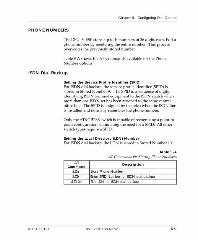
61204.011L1-1 DSU IV ESP User Manual 55
Chapter 9. Configuring Dial Options
PHONE NUMBERS
The DSU IV ESP stores up to 10 numbers of 36 digits each. Edit aphone number by reentering the entire number. This processoverwrites the previously stored number.
Table 9-A shows the AT Commands available for the PhoneNumber options.
ISDN Dial Backup
Setting the Service Profile Identifier (SPID)For ISDN dial backup, the service profile identifier (SPID) isstored in Stored Number 9. The SPID is a sequence of digitsidentifying ISDN terminal equipment to the ISDN switch whenmore than one ISDN set has been attached to the same centraloffice line. The SPID is assigned by the telco when the ISDN lineis installed and normally resembles the phone number.
Only the AT&T 5ESS switch is capable of recognizing a point-to-point configuration, eliminating the need for a SPID. All otherswitch types require a SPID.
Setting the Local Directory (LDN) NumberFor ISDN dial backup, the LDN is stored in Stored Number 10.
Table 9-AAT Commands for Storing Phone Numbers
AT Command
Description
&Zn= Store Phone Number&Z9= Enter SPID Number for ISDN dial backup
&Z10= Edit LDN for ISDN dial backup

56 DSU IV ESP User Manual 61204.011L1-1
Chapter 9. Configuring Dial Options
SW56 AUTO ANSWER
The SW56 Auto Answer option is used to specify how incomingcalls are to be answered. If ENABLED, incoming calls areautomatically answered by the DSU IV. If DISABLED, anincoming call can be answered manually, by an AT or V.25command from the DTE, or by raising TR from the DTE.
DBU OPTIONS
The DBU Options are used to select the modes of operation forthe Dial Backup features. There are ten standard options avail-able with additional options for specific backup services. Table9-B lists the DBU options and their AT commands for all models.
Standard DBU Options
Automatic DBU
The Automatic DBU option specifies whether the unit automati-cally enters dial backup mode or waits for manual setup. Thefactory default setting is Disabled.
Number to Dial
The Number to Dial option offers a selection of stored numbersfor the unit to automatically dial. If the leased line fails, and theDSU IV ESP is set to originate, it dials the numbers (in chrono-logical order) specified under this option to set up the dialbackup line. The factory default setting is Dial With #1.
Originate/Answer
This option specifies whether the DSU IV ESP originates or waitsto answer if the dedicated circuit fails. One end must be set toOriginate and the other to Answer. The factory default setting isAnswer.
61204.011L1-1 DSU IV ESP User Manual 57
Chapter 9. Configuring Dial Options
DBU Criteria
These options specify the conditions that will cause the DSU IVESP to enter the backup mode.
When Out of Service (OOS)When enabled, the DSU IV ESP enters backup mode if an out-of-service condition is detected. The factory default setting isEnable.
No Receive (RX) SignalWhen enabled, the DSU IV ESP enters backup mode when a lossof signal is detected. The factory default setting is Enable.
No Sealing CurrentWhen enabled, the DSU IV ESP enters backup mode when a lossof sealing current is detected. The factory default setting isEnable.
When all 1s/0sWhen this option is enabled, the DSU IV ESP monitors thereceive data for strings of 1s or 0s that are longer than the FailTimer. If this condition is detected, the local DSU IV ESP ini-tiates a handshake routine with the remote unit to determine ifthe DTE is generating the constant data pattern or if the networkhas failed.
Answer AlwaysIf enabled, the answer unit answers any incoming call regardlessof failed conditions.
Weekend LockoutIf enabled, no backup will occur from midnight Friday tomidnight Sunday.
Weekend and daily lockout apply to automatic DBU only. ManualDBU is not affected. Also, this parameter affects the originate endonly. The answer end remains DBU-capable at all times.

58 DSU IV ESP User Manual 61204.011L1-1
Chapter 9. Configuring Dial Options
Daily LockoutEnable/disable the daily lockout specified by the fields EnableHour and Disable Hour.
Lockout StartEnter the hour that the daily lockout begins and dial backup isdisabled (0 to 23). Only applies if the Daily Lockout parameter isENABLED.
Lockout EndEnter the hour that the daily lockout ends and dial backup isreactivated (0 to 23). Only applies if the Daily Lockout param-eter is ENABLED.
Auto Restore
Once the DDS circuit is down, the DSU IV ESP remains inbackup until the DDS circuit is active for the length of timespecified for the restore timer. The selection is entered in min-utes (up to 255). If set to 0, the DDS must be restored manually.The factory default setting is 1 minute.
RESTORE TIMER(0=OFF): __ __ MIN
Redial Counter
This option sets the number of times the DSU IV ESP re-dials thefar end when entering backup mode. The redial count, which ismanually entered, can be up to a maximum of 99 attempts. If theDSU IV ESP encounters a busy or reorder, it attempts to establishthe call the specified number of times. The factory defaultsetting is 5.
ENTER REDIALCOUNT: __ __
Fail Timer
This option sets the amount of time the dedicated circuit failurecondition must be active before the DSU IV ESP attempts
61204.011L1-1 DSU IV ESP User Manual 59
Chapter 9. Configuring Dial Options
backup. The amount of time, which is manually entered, can beup to 990 seconds. The factory default setting is 30 seconds.
AUTO DBU FAILTIME: __ __ x 10sec
Wait to Redial
This option works in conjunction with the preceding RedialCounter. It selects the amount of time between redial attempts toconnect the backup line. The amount of time, which is manuallyentered, can be up to 99 seconds. The factory default setting is10 seconds.
WAIT TO REDIALTIME: __ __ SEC

60 DSU IV ESP User Manual 61204.011L1-1
Chapter 9. Configuring Dial Options
Table 9-BDBU Options AT Commands for All Models
Front Panel AT Command
Description
Automatic DBU1=DISABLED _K0 Automatic DBU disabled2=ENABLED _K1 Automatic DBU enabledNumber to Dial1=DBU WITH #1 _B0 Dial stored #12=DBU WITH #2 _B1 Dial stored #2Originate/Answer1=DBU ORIGINATE _E0 Originates call if DDS fails2=DBU ANSWER _E1 Answers call if DDS failsDBU CriteriaWHEN OUT OF SERVICE1=Disabled _G0 No DBU for OOS2=Enabled _G1 DBU when OOSNO RECEIVE (RX) SIGNAL1=Disabled _H0 No DBU when RX signal absent2=Enabled _H1 DBU when RX signal absentNO SEALING CURRENT1=Disabled _I0 No DBU when sealing current absent2=Enabled _I1 DBU when sealing current absentWHEN ALL 1S/0S1=Disabled _P0 No DBU when all 1s/0s detetected2=Enabled _P1 DBU when all 1s/0s condition existsANSWER ALWAYS1=Disabled none Answer unit answers only under
specified conditions.
2=Enabled none Answer unit answers any incoming call regardless of failed condition.
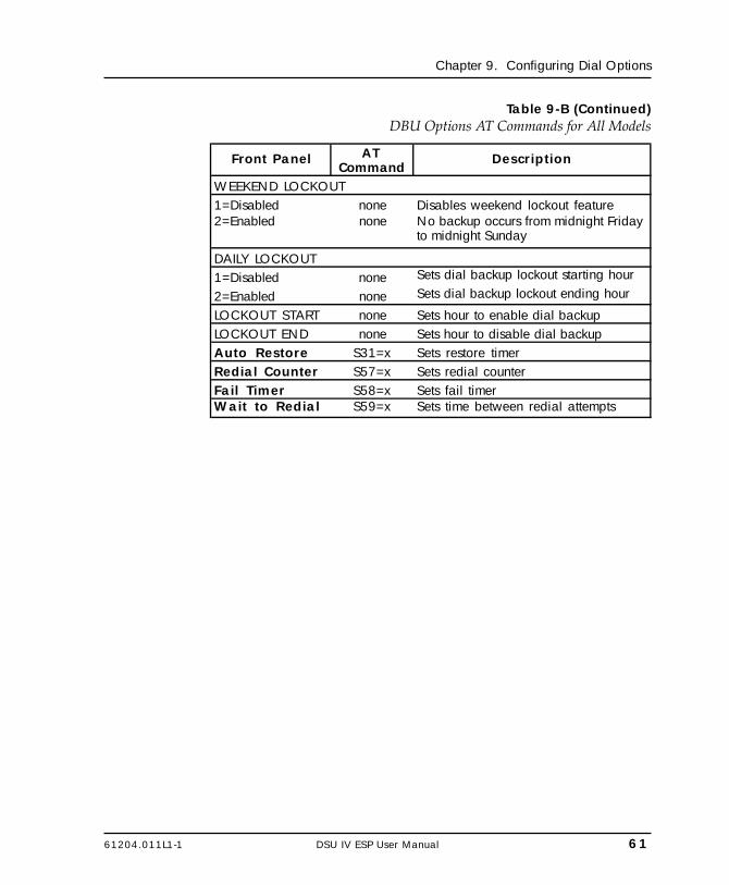
61204.011L1-1 DSU IV ESP User Manual 61
Chapter 9. Configuring Dial Options
Table 9-B (Continued)DBU Options AT Commands for All Models
Front Panel AT Command
Description
WEEKEND LOCKOUT1=Disabled none Disables weekend lockout feature2=Enabled none No backup occurs from midnight Friday
to midnight Sunday
DAILY LOCKOUT1=Disabled none Sets dial backup lockout starting hour
2=Enabled none Sets dial backup lockout ending hour
LOCKOUT START none Sets hour to enable dial backupLOCKOUT END none Sets hour to disable dial backupAuto Restore S31=x Sets restore timerRedial Counter S57=x Sets redial counterFail Timer S58=x Sets fail timerWait to Redial S59=x Sets time between redial attempts

62 DSU IV ESP User Manual 61204.011L1-1
Chapter 9. Configuring Dial Options
DBU Options for S4W Card
Network TypeThis option selects the company providing the switched digitalservice. When US Sprint is selected, an automatic echo cancelersuppressor tone is emitted by the DSU IV ESP when dialing.Options include: AT&T/MCI/Other and US Sprint.
DBU Options for V.34 Card
Table 9-C shows the equivalent AT commands for setting ErrorControl, Flow Control , and Compression options.
Error ControlThis option determines the type of error control to be negotiatedat the start of a V.34 modem connection. The factory defaultsetting is AUTO V.42/MNP.
Flow ControlThis option is used to select the type of flow control used by theV.34 modem. The factory default setting is CTS Only.
CompressionThis option is used to select V.42 bis data compression for V.32bis or V.34 operation when running asynchronously. Whenenabled, data throughput speeds as high as 57.6 kbps may beachieved. For synchronous applications, the speed is limited to amaximum of 33.6 kbps for the V.34. The factory default setting isEnabled.

61204.011L1-1 DSU IV ESP User Manual 63
Chapter 9. Configuring Dial Options
Table 9-CDBU Options AT Commands for V.34 Card
DBU Options AT CMD
Description
Error Control
1=BUFFERED \N0 Normal operation. No error control. Allows speed matching, buffering, and flow control.
2=DIRECT \N1 Direct operation. No error control, no buffer, and no flow control.
3=RELIABLE MNP \N2 Reliable MNP operation. Uses MNP error control.
4=AUTO MNP \N3 Auto-Reliable MNP operation. Tries MNP error control first; uses normal operation if necessary.
5=RELIABLE V.42 \N4Reliable V.42 (LAPM) operation. Uses V.42 (LAPM) error control. If V.42 (LAPM) error control cannot be used the call is disconnected.
6=REL. V.42/MNP \N5Reliable V.42 (LAPM) or MNP operation. Uses either V.42 (LAPM) or MNP error control. If neither can be used the call is disconnected.
7=AUTO V.42/MNP \N6
Auto-Reliable V.42 (LAPM) or MNP operation. Tries to use V.42 (LAPM) error control first, and MNP error control next. If neither can be used, then Normal operation is used.
Flow Control 1=DISABLED \Q0 Flow control disabled2=XON/XOFF \Q1 Enables XOn/XOff flow control3=CTS ONLY \Q2 Enables CTS flow control from DCE
4=RTS/CTS \Q3 Enables CTS flow control from DCE and RTS from DTE
5=UNI XON/XOFF \Q4 Unidirectional XOn/XOff Compression1=DISABLED %C0 Compression disabled2=ENABLED %C1 Compression enabled
64 DSU IV ESP User Manual 61204.011L1-1
Chapter 9. Configuring Dial Options
DBU Options for ISDN Card
Switch TypeThis option selects the type of telco CO switch providing theISDN service. There are three options for ISDN switch types:
• AT&T 5ESS• NT DMS-100• National ISDN
DBU Passcode
The dial backup passcode adds an additional level of security tothe DSU IV ESP. A passcode of one to ten characters can beprogrammed into the unit.
When a dial backup connection is established, the originate unittransmits a pre-programmed passcode to the answer unit overthe dial backup connection before the connection is consideredvalid. The answer unit compares the received passcode to a pre-programmed passcode. If the passcode matches, the receive unitsends a Passcode OK message to the originate unit and goes on-line. If the passcode does not match, the receive unit sends anInvalid Passcode message to the originate unit and terminatesthe dial backup connection. If a passcode is not received by ananswer unit with passcode enable, or if the Passcode OKmessage is not received by an originate unit with passcodeenable, the dial backup connection is terminated.
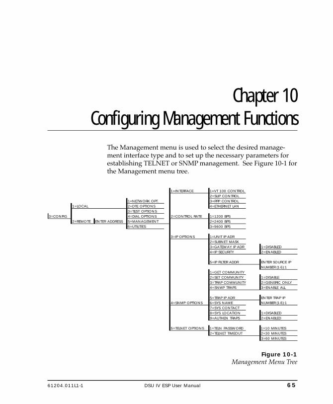
61204.011L1-1 DSU IV ESP User Manual 65
Chapter 10. Configuring Management Functions
Chapter 10Configuring Management Functions
The Management menu is used to select the desired manage-ment interface type and to set up the necessary parameters forestablishing TELNET or SNMP management. See Figure 10-1 forthe Management menu tree.
1=INTERFACE 1=VT 100 CONTROL2=SLIP CONTROL
1=NETWORK OPT. 3=PPP CONTROL1=LOCAL 2=DTE OPTIONS 4=ETHERNET LAN
3=TEST OPTIONS3=CONFIG 4=DIAL OPTIONS 2=CONTROL RATE 1=1200 BPS
2=REMOTE ENTER ADDRESS 5=MANAGEMENT 2=2400 BPS6=UTILITIES 3=9600 BPS
3=IP OPTIONS 1=UNIT IP ADR2=SUBNET MASK3=GATEWAY IP ADR 1=DISABLED4=IP SECURITY 2=ENABLED
5=IP FILTER ADDR ENTER SOURCE IPNUMBER (1-5):1
1=GET COMMUNITY2=SET COMMUNITY 1=DISABLE3=TRAP COMMUNITY 2=GENERIC ONLY4=SNMP TRAPS 3=ENABLE ALL
5=TRAP IP ADR ENTER TRAP IP4=SNMP OPTIONS 6=SYS NAME NUMBER (1-5):1
7=SYS CONTACT8=SYS LOCATION 1=DISABLED9=AUTHEN TRAPS 2=ENABLED
5=TELNET OPTIONS 1=TELN PASSWORD 1=10 MINUTES2=TELNET TIMEOUT 2=30 MINUTES
3=60 MINUTES
Figure 10-1Management Menu Tree

66 DSU IV ESP User Manual 61204.011L1-1
Chapter 10. Configuring Management Functions
Interface
Select the management interface type (VT 100 terminal, SLIP, orPPP) or select Ethernet LAN (ESP Ethernet card must be in-stalled).
Control Rate
Select the control port operating speed to match the connecteddevice (this selection only applies when the interface options isset for VT 100 terminal, SLIP, or PPP).
IP Options
When configuring the DSU IV with the front panel, use the "*" key toenter a decimal point.
Unit IP AddressEnter the DSU IV ESP IP address in dotted decimal notation.
Subnet MaskEnter the subnet number in dotted decimal notation. Thisaddress is available from the network administrator.
Gateway IP AddressEnter the Gateway node IP address in dotted decimal notation.This address is necessary only if the DSU IV and networkmanager are connected through a Gateway node. If an IP packetwith an unknown IP address is received, the DSU IV sends it tothe Gateway.
IP SecurityEnable/disable the IP security option. If enabled, the DSU IVonly accepts management commands from the IP addresses (upto 5) entered into the IP Filter Address field.
IP Filter AddressEnter the IP addresses of the management stations from whichthe DSU IV should accept management commands. This filtermust be enabled though the IP Security field.
61204.011L1-1 DSU IV ESP User Manual 67
Chapter 10. Configuring Management Functions
SNMP Options
The following options must be configured when SNMP manage-ment is used.
Get CommunityFor SNMP operation, view and edit the Get community string.The DSU IV uses this string to validate SNMP Get (read) re-quests. The default value is public. If using front panel entry,see the section Entering Letters Using the Front Panel in thischapter for more information.
Set CommunityFor SNMP operation, view and edit the Set community string.The DSU IV uses this string to validate SNMP Set (write) re-quests. The default value is private. If using front panel entry,see the section Entering Letters Using the Front Panel in thischapter for more information.
Trap CommunityFor SNMP operation, view and edit the Trap community string.The DSU IV sends this string in SNMP trap messages to thenetwork manager. The default value is dsuiv. If using frontpanel entry, see the section Entering Letters Using the Front Panelin this chapter for more information.
SNMP TrapsSpecify which traps the DSU IV will send to the network man-ager. When enabled, the DSU IV sends SNMP traps to networkmanagers for alarm conditions. The options are DISABLE,GENERIC ONLY, and ENABLE ALL. The GENERIC ONLYoption enables the Generic Standard traps specified in the SNMPstandard, RFC 1157. The ALL option sends both Generic Stan-dard traps and the enterprise-specific traps specified in theADTRAN DSU IV MIB.
Trap IP AddressEnter up to five IP addresses of the SNMP managers to whichthe DSU IV should send traps.

68 DSU IV ESP User Manual 61204.011L1-1
Chapter 10. Configuring Management Functions
System Name, Contact, and LocationThese data fields are general information strings (defined inMIB-II standard, RFC 1213) which can be stored by the user andretrieved by the SNMP management station. If using front panelentry, see the section Entering Letters Using the Front Panel in thischapter for more information.
Authentication TrapsEnable/disable the DSU IV to send SNMP authentication trapsto the SNMP management station. If enabled, the DSU IV sendsthese traps when an SNMP request with an invalid communityname string is received.
The ADTRAN DSU IV ESP MIB is available in the support section ofthe ADTRAN Web page at www.adtran.com.
TELNET Options
TELNET PasswordView/edit the TELNET password. If using front panel entry, seethe section Entering Letters Using the Front Panel in this chapterfor more information.
TELNET TimeoutSelect the inactivity time limit. If the unit is idle for the desig-nated amount of time the unit times out, closing the TELNET

61204.011L1-1 DSU IV ESP User Manual 69
Chapter 10. Configuring Management Functions
session.ENTERING LETTERS USING THE FRONT PANEL
Some Management menus require the entry of letters rather thannumbers. When configuring the unit using the front panel,special steps must be taken in order to perform these entries.The following example of entering the TELNET Passwordillustrates this procedure:
1. Press 5, then Enter to select TELNET OPTIONS from theManagement menu.
2. Press 1, then Enter to select TELN PASSWORD.3. Press the Up Arrow to delete the existing entry.4. Press the Shift key. The cursor appears as an underscore
( _ ).5. Use the Up and Down Arrow keys to scroll to the appropri-
ate letter.6. Once the letter is displayed, press Shift. A block cursor
appears in the next field.7. To enter another letter, press Shift. The cursor again appears
as an underscore.8. Repeat this procedure until all letters have been entered.9. Once password entry is complete, press the Enter key.
A block cursor signifies movement from field to field. When this cursoris active, pressing the Up Arrow key deletes the current entry of thatfield. Pressing the Down Arrow key advances the cursor to the nextfield. An underscore cursor signifies letter entry. When active,pressing the Up and Down Arrow keys scrolls the alphabet.

70 DSU IV ESP User Manual 61204.011L1-1
Chapter 10. Configuring Management Functions
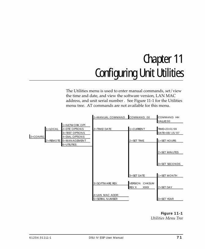
61204.011L1-1 DSU IV ESP User Manual 71
Chapter 11. Configuring Unit Utilities
Chapter 11Configuring Unit Utilities
The Utilities menu is used to enter manual commands, set/viewthe time and date, and view the software version, LAN MACaddress, and unit serial number . See Figure 11-1 for the Utilitiesmenu tree. AT commands are not available for this menu.
1=MANUAL COMMAND COMMAND: 00 COMMAND: HHVALUE:00
1=NETWORK OPT.1=LOCAL 2=DTE OPTIONS 2=TIME/DATE 1=CURRENT TIME=23:01:59
3=TEST OPTIONS DATE=08/15/973=CONFIG 4=DIAL OPTIONS
2=REMOTE 5=MANAGEMENT 2=SET TIME 1=SET HOURS6=UTILITIES
2=SET MINUTES
3=SET SECONDS
3=SET DATE 1=SET MONTH
3=SOFTWARE REV. VERSION CHKSUMREV X XXXX 2=SET DAY
4=LAN MAC ADDR.5=SERIAL NUMBER 3=SET YEAR
Figure 11-1Utilities Menu Tree

72 DSU IV ESP User Manual 61204.011L1-1
Chapter 11. Configuring Unit Utilities
Manual Command
The Manual Command option is a shortcut method for enteringconfiguration and control commands for the DSU IV ESP. Figure 11-1shows the menu path for the manual command. The availablemanual commands are listed in Table 11-A. When using thefront panel, perform the following steps to enter a manualcommand:
1. Select 3=CONFIG from the Main menu.2. Select 1=LOCAL.3. Select 6=UTILITIES.4. Select 1=MANUAL COMMAND.5. The first display prompts for command number entry:
COMMAND:00
Use the Up Arrow key to delete the current entry, then usethe number keys to enter the new value. Press Shift toactivate letters A-F.
6. Press Enter to complete the Command entry.7. Once the command number is entered, the display shows
both the command number and the present value or settingfor the command. The command value can be edited orreissued with the existing value.
COMMAND: XXVALUE: 00
8. Use the number keys to enter the hexadecimal value. PressEnter to complete. The system briefly displays CommandAccepted (if the entry is valid) and returns to the activemenu.

61204.011L1-1 DSU IV ESP User Manual 73
Chapter 11. Configuring Unit Utilities
Table 11-AManual Commands
Command Description Command ValueAT Command Echo Disable 82 00 Enable 82 01AT Result code Enable 85 00 Disable 85 01AT Long or Short code Short form (Numeric) 86 00 Long form (Verbose) 86 01AT Escape Character 2 00 to FFAT CR Character 3 00 to FFAT LF Character 4 00 to FFAT BS Character 5 00 to FFAT Escape Char. Timer 0C 00 to FFAbort Call Timer 7 00 to FFDTR Recognize Delay 19 00 to FFDTR Initiated Command Timeout 28 00 to FFLoad Factory Opt. Option Set #1 8A 00 Option Set #2 8A 01 Option Set #3 8A 02 Option Set #4 8A 03Network Address Lock Network Addr. Unlock C3 00 Network Addr. Lock C3 01Front Panel En/Dis Disable AA 00 Enable AA 01

74 DSU IV ESP User Manual 61204.011L1-1
Chapter 11. Configuring Unit Utilities
Time/Date
View/set the current time and date. Entering this information isonly necessary for the Weekend and Time of Day Lockoutfeatures.
The DSU IV ESP has been tested for year 2000 compliance.
Software Revision
View the current revision of the software installed in the DSU IV.
LAN MAC Address
View the LAN MAC address. This address is available when theESP ethernet option card is installed.
Serial Number
View the DSU IV's serial number.

61204.011L1-1 DSU IV ESP User Manual 75
Chapter 12. Testing and Troubleshooting
Chapter 12Testing and Troubleshooting
TEST OVERVIEW
The DSU IV ESP performs a variety of diagnostic functions thatisolate portions of the circuit to identify the problem source.Tests may be initiated and terminated through the front panel,VT 100 terminal, SNMP, or TELNET. In asynchronous mode, ATcommands can control the testing from the DTE interface. Forsynchronous operation, V.25 bis commands can provide testcontrol.
The unit also responds to standard DDS network tests initiatedfrom telco test centers. In addition, it can run several tests suchas local and remote loopbacks to aid in problem isolation. SeeFigure 12-1.
LOCALDSU/CSU
REMOTEDSU/CSUDTE DTE
RD
TD TELCO
Rx
Tx
Rx
Tx
RD
TD
Rx
Tx
Rx
Tx
Figure 12-1Normal Operation Before Initiating Loopback Test
All diagnostic tests disrupt data flow.

76 DSU IV ESP User Manual 61204.011L1-1
Chapter 12. Testing and Troubleshooting
Initiating a Test
Initiate tests using the following procedure:
1. Select Test from the Main menu by pressing 2, then pressEnter.
2. Specify local, remote, or DBU testing by selecting the corre-sponding number, followed by Enter.
3. Use the Up and Down arrows to view test options.4. Select a test from the available options by pressing the
corresponding number, followed by Enter.
The example in Figure 12-2 shows the menu path for initiating alocal DTE and Loop test.
1=DTE & LOOP(LL)
2=LOOP ONLY (RT)
2=TEST 1=LOCAL UNIT 3=DTE ONLY
2=REMOTE UNIT 4=DTE WITH TP
3=DBU CONNECTION 5=TEST PATTERN
6=SELF TEST
Figure 12-2Initiating a Test
Once a test is initiated, Please Wait is displayed briefly, followedby the status screen.

61204.011L1-1 DSU IV ESP User Manual 77
Chapter 12. Testing and Troubleshooting
Test Status Display
The Test Status display appears automatically during a test. TheTest Status display is similar to the status screen described in thechapter Status, with additional prompts for the type of test andthe number of errors (for tests with a test pattern).
Figure 12-3 shows an example of a Test Status Display for a testwith a test pattern.
TEST PATTERNTST ERR = 00
LOOP 56KDTE 56K SYNC
TR SR LLB RLBOFF OFF OFF OFF
UNIT IN TESTLOOP IS NORMAL
While this menu is on the display:Press 1 to clear errors. Press 2 to inject an error.
Use the Up and Down arrows to display other status screens.
Figure 12-3Sample Test Status Displays
Exiting a Test
During a test, press Quick to access the Exit Test/Display Statusmenu or press Cancel to return to the Main menu. The ExitTest/Display Status menu provides the following options, whichare available only after a test has been initiated (see Figure 12-4):
Exit Test Exits the current test and returns to theMain menu.
Display Status Reenters test display.

78 DSU IV ESP User Manual 61204.011L1-1
Chapter 12. Testing and Troubleshooting
1=DTE & LOOP(LL)
2=LOOP ONLY (RT)
3=DTE ONLY
4=DTE WITH TP 1=2047 PATTERN
1=LOCAL UNIT 2=511 PATTERN
3=STRESS PTRN #1
5=TEST PATTERN 4=STRESS PTRN #2
5=STRESS PTRN #3
6=SELF TEST 6=STRESS PTRN #4
2=TEST 1=2047 PATTERN
2=REMOTE UNIT ENTER TEST UNIT 2=511 PATTERN
ADDRESS:0 3=STRESS PTRN #1
4=STRESS PTRN #2
5=STRESS PTRN #3
3=DBU CONNECTION 1=DIAL STORED # 6=STRESS PTRN #4
2=ENTER DIAL # 7=DATA FROM DTE
3=REDIAL LAST #
Figure 12-4Complete Test Menu

61204.011L1-1 DSU IV ESP User Manual 79
Chapter 12. Testing and Troubleshooting
TROUBLESHOOTING
This section is intended to provide a quick and easy means ofdiagnosing suspected problems associated with local or remotelyattached ADTRAN DSU/CSUs.
Messages from the DSU/CSU
Messages on the LCD display and LEDs gives informationconcerning the status of the unit and the local loop. If the AlarmLED is On, one or more of the messages shown in Table 12-A aredisplayed on the LCD.
The Status menu must be selected in order for the unit to display statusmessages. Pressing Quick returns to the Main menu where STATUScan be selected.
Table 12-AMessages from the DSU/CSU
Message Meaning Probable Cause Action
LOOP IS NORMAL
Good local loop signal being received from the telco.
Indicates good local loop.
No action required; unit properly connected to telco circuit.
OPEN LOOP
Unit not receiving a signal from the telco.
Bad telco cable from the DSU to telco jack or bad circuit to telco.
Replace telco cable from DSU to wall jack. If a problem persists, contact telco provider.
NO RX SIGNAL
Unit detects sealing current but no data signal from telco.
Bad conductor in telco cable from DSU to telco jack or bad circuit to telco.
Replace telco cable from DSU to wall jack. If a problem persists, contact telco provider.
OOS/OOFFROM NET
Unit detects an out-of-service or out-of-frame condition from the telco.
Telco is having problems with DDS circuit or remote unit is turned off or disconnected.
Check remote unit. Contact telco service provider.
CHECK TELCO LINETransmit/receive pair reversal detected.
Telco wall jack wired incorrectly.
Switch wire pairs in wall jack or contact telco service provider.
TEST FROM TELCO
Telco activated a loopback to test the DDS circuit.
Telco is testing circuit. Wait until test is complete or contact telco service provider.

80 DSU IV ESP User Manual 61204.011L1-1
Chapter 12. Testing and Troubleshooting
Troubleshooting New Installs
Before initiating diagnostics on a newly installed unit and/orDDS circuit and before contacting ADTRAN Technical Support,please check the items in Table 12-B to ensure the unit is config-ured properly.
After verifying the items listed in Table 12-B, the unit shouldoperate properly and display the following:
DATA MODELOOP IS NORMAL
If a status message other than DATA MODE LOOP IS NOR-MAL is shown, begin performing diagnostics described in thesection Test Sequence for Troubleshooting New Installs or ExistingCircuits.
Table 12-BTroubleshooting New Installs
Configuration Item to Check Option Selection Action
DTE Type EIA-232 or V.35From the Configuration menu, select the type of DTE interface option to connect to the DSU/CSU.
Loop Rate Auto, 2.4 to 64 kbpsFrom the Configuration menu, select the DDS loop rate of the DDS circuit.
Data Format Async or SyncFrom the Configuration menu, select the type of data to be used.
DTE Cable N/AVerify DTE cable connection to the proper DTE connector on the DSU/CSU.
Telco Cable N/AVerify the telco cable is securely connected to the DSU/CSU and wall jack.
Power the unit Off and then On. N/A
Verify the unit passes self test during power-up (displayed on the LCD).

61204.011L1-1 DSU IV ESP User Manual 81
Chapter 12. Testing and Troubleshooting
Test Sequence for Troubleshooting New Installs or Existing Circuits
If your DSU is suspected of having problems, perform a SelfTest to determine whether the unit is in good health.
If your DSU is receiving excessive errors requiring retransmis-sion of data, first perform a DTE with Test Pattern to determinewhether the unit's internal transmitter and receiver are operatingerror free. If problem persists, perform a Remote Test to verifythe connection between the local and remote unit is error free.Run the test using all available test patterns.
If an external BERT tester is available, these additional tests may beperformed:
• DTE & Loop Test• DTE Only Test• Loop Only Test
If the unit fails any of these tests or the problem has not beendetermined, contact ADTRAN Technical Support; see inside backcover.

82 DSU IV ESP User Manual 61204.011L1-1
Chapter 12. Testing and Troubleshooting
LOCAL UNIT DIAGNOSTICS
The local DSU IV ESP can perform six different tests; see Table12-C.
Table 12-CTest AT Commands
FrontPanel
Display
ATCommand
Description
DTE & Loop (LL) &T10 TD/RD and RX/TX LoopbacksLoop Only (RT) &T11 RX/TX Loopback at Network InterfaceDTE Only &T1 TX/RX Loopback at DTE InterfaceDTE with TP &T8 TX/RX Loopback with Test PatternTest Pattern &T9 Transmit/Receive Test PatternSelf Test Z Check Internal Components (Resets Unit)Exit Test &T0 Stops test, returns to data modeTD = Customer Transmit DataRD = Customer Receive DataTX = Network Transmit DataRX = Network Receive Data
The test patterns shown in Table 12-D are available for the DTEwith Test Pattern and Test Pattern tests.

61204.011L1-1 DSU IV ESP User Manual 83
Chapter 12. Testing and Troubleshooting
Table 12-DDTE With Test Pattern Commands
FrontPanel
ATCommand
Description
1=2047 PATTERN _T0&T8 Standard 2047 random data pattern.2=511 PATTERN _T1&T8 Standard 511 random data pattern.
3=STRESS PTRN #1 _T2&T8
Stress pattern with alternating high and low ones densities. Repeated pattern of 100 octets: 1111 1111, followed by 100 octets: 0000 0000.
4=STRESS PTRN #2 _T3&T8
Stress pattern with alternating medium and low ones densities. Repeated pattern of 100 octets: 0111 1110, followed by 100 octets: 0000 0000.
5=STRESS PTRN #3 _T4&T8Stress pattern with medium ones density. Continuous series of octets: 0011 0010.
6=STRESS PTRN #4 _T5&T8Stress pattern with low ones density. Continuous series of octets: 0100 0000.

84 DSU IV ESP User Manual 61204.011L1-1
Chapter 12. Testing and Troubleshooting
DTE & Loop (LL)
The DTE & Loop test splits the DSU IV ESP into two separateDTE and loop interface sections and then loops the receive dataof each interface back to its respective transmit data. The DTE &Loop test provides a bidirectional loopback at the DSU/CSU.Figure 12-5 illustrates the loopback points and the signal pathsfor this test.
LOCALDSU/CSUDTE
Rx
Tx
TELCONET Rx
NET Tx
DTE Rx
DTE Tx
Figure 12-5DTE & Loop Test
Test Purpose
The DTE & Loop test is used for the following purposes:
• Verify integrity of the DTE interface and cable.• Provide a loopback for network tests.
Interpreting Test Results
A BERT tester must be used to interpret the test results of a DTE& Loop test.

61204.011L1-1 DSU IV ESP User Manual 85
Chapter 12. Testing and Troubleshooting
Loop Only (RT)
The Loop Only (RT) test allows the loop interface and a majorportion of the DTE interface for the local DSU IV ESP to be testedfrom the remote site over the actual communication circuit.Figure 12-6 illustrates the loopback point and the signal paths forthis test.
LOCALDSU/CSU
TELCODTEInterface
NET Rx
NET Tx
DTE Rx
DTE Tx
Figure 12-6Loop Only Test
Test Purpose
The Loop Only test is used to provide a loopback for networktests.
Interpreting Test Results
The Loop Only test is used for the purpose of looping the DDScircuit back to the telco. No test results are available from thelocal DSU IV ESP.
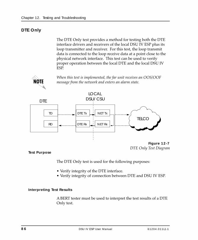
86 DSU IV ESP User Manual 61204.011L1-1
Chapter 12. Testing and Troubleshooting
DTE Only
The DTE Only test provides a method for testing both the DTEinterface drivers and receivers of the local DSU IV ESP plus itsloop transmitter and receiver. For this test, the loop transmitdata is connected to the loop receive data at a point close to thephysical network interface. This test can be used to verifyproper operation between the local DTE and the local DSU IVESP.
When this test is implemented, the far unit receives an OOS/OOFmessage from the network and enters an alarm state.
LOCALDSU/CSUDTE
RD
TD
TELCONET Rx
NET Tx
DTE Rx
DTE Tx
Figure 12-7DTE Only Test Diagram
Test Purpose
The DTE Only test is used for the following purposes:
• Verify integrity of the DTE interface.• Verify integrity of connection between DTE and DSU IV ESP.
Interpreting Test Results
A BERT tester must be used to interpret the test results of a DTEOnly test.

61204.011L1-1 DSU IV ESP User Manual 87
Chapter 12. Testing and Troubleshooting
DTE With Test Pattern
The DTE with TP (test pattern) test is similar to the DTE Onlytest described previously except the test pattern is generatedusing the DSU/CSU internal test pattern generator. This test canbe used to detect deficiencies within the internal drivers andreceivers of the DSU IV ESP. Figure 12-8 illustrates the loopbackpoint and the data paths for this test.
LOCALDSU/CSU
DTE
Rx
Tx
NET Rx
NET Tx
DTE Rx
DTE Tx
ErrorInject
Test PatternGenerator
ErrorClear
Test PatternDetector
Figure 12-8DTE with Test Pattern
Test Purpose
A DTE test using a test pattern is used for the following pur-poses:
• Verify integrity of the DTE interface.• Verify integrity of connection between DTE and DSU IV ESP.

88 DSU IV ESP User Manual 61204.011L1-1
Chapter 12. Testing and Troubleshooting
Interpreting Test Results
If the unit is functioning properly, the DSU IV ESP displays:
DTE WITH TPTST ERR=XX
The first line of the display indicates the type of test beingperformed, while the second line of the display indicates thenumber of errors accumulated by the test pattern detector.
If errors occur during this test, the test error count can be reset tozero by pressing 1. To verify proper operation of this test, singlebit errors can be injected into the transmitted test pattern bypressing 2. These errors appear on the TEST ERR display.

61204.011L1-1 DSU IV ESP User Manual 89
Chapter 12. Testing and Troubleshooting
Test Pattern
The Test Pattern option converts the local DSU IV ESP into aBERT tester for the purpose of testing the DDS circuit. If this testis used, the remote DSU/CSU must be in loopback or transmit-ting a test pattern. Figure 12-9 illustrates the data paths for thismode.
LOCALDSU/CSU
NET Rx
NET Tx
DTE Rx
DTE Tx
ErrorInject
Test PatternGenerator
ErrorClear
Test PatternDetector
REMOTEDSU/CSU
DTE Rx
DTE Tx
NET Rx
NET Tx
ErrorInject
Test PatternGenerator
ErrorClear
Test PatternDetector
TELCO
Figure 12-9Test Pattern Only
Test Purpose
Testing using a test pattern is used for the following purposes:
• Transmits user-selected test pattern using an internal testpattern generator, and compares the received data usinginternal test pattern detector to detect if there are any errors onthe DDS circuit.
• Injects errors and verifies the unit transmits data across thecommunication circuit to the remote unit.
• Helps determine from which direction the circuit is receivingerrors.
Interpreting Test Results
If the unit is functioning properly, the test error count should be0.
90 DSU IV ESP User Manual 61204.011L1-1
Chapter 12. Testing and Troubleshooting
Self Test
The Self Test verifies current operation of the DSU IV ESP. It canbe performed at any time and is recommended if there is anyquestion about the DSU's health.
Test Purpose
The purpose of this test it to determine if the DSU is functioningproperly.
Interpreting Test Results
Once Self Test is activated, the LEDs cycle on and off as thesystem runs the self test. A pass or fail status will be displayedon the LCD along with a checksum indicating the currentfirmware revision.

61204.011L1-1 DSU IV ESP User Manual 91
Chapter 12. Testing and Troubleshooting
REMOTE UNIT DIAGNOSTICS
A remote DSU IV ESP can perform seven different tests; seeTable 12-E.
Table 12-ERemote Tests and AT Commands
FrontPanel
ATCommand
Description
1=2047 PATTERN _T0&T7 Standard 2047 random data pattern2=511 PATTERN _T1&T7 Standard 511 random data pattern3=STRESS PTRN #1 _T2&T7 DDS Stress Pattern #14=STRESS PTRN #2 _T3&T7 DDS Stress Pattern #25=STRESS PTRN #3 _T4&T7 DDS Stress Pattern #36=STRESS PTRN #4 _T5&T7 DDS Stress Pattern #47=DATA FROM DTE &T6 Data from DTE
The Remote Unit submenu allows a remotely installed DSU to beplaced into loopback. There are six test patterns to choose fromor Data from the DTE may be selected.
DTE Rx
DTE Tx
NET Rx
NET Tx
LOCALDSU/CSU
NET Rx
NET Tx
DTE Rx
DTE Tx
ErrorInject
Test PatternGenerator
ErrorClear
Test PatternDetector
TELCO
REMOTEDSU/CSUDTE
Local Unit Initiates Test
Rx
Tx
Figure 12-10V.54 RDL with Test Pattern

92 DSU IV ESP User Manual 61204.011L1-1
Chapter 12. Testing and Troubleshooting
Test Purpose
The test purpose is to test the local DSU, the DDS circuit, and theremote DSU.
Initiating
Follow the menu path outlined in Figure 12-11 to place a remoteDSU IV ESP into loopback.
1=2047 PATTERN
1=LOCAL UNIT 2=511 PATTERN
2=TEST ENTER TEST UNIT 3=STRESS PTRN #1
2=REMOTE UNIT ADDRESS:0 4=STRESS PTRN #2
5=STRESS PTRN #3
3=DBU CONNECTION 6=STRESS PTRN #4
7=DATA FROM DTE
Figure 12-11Initiating a Remote Test
After selecting Remote Unit from the menu, the followingprompt is displayed for entering the address for the remote unit:
ENTER TEST UNITADDRESS:XX
Use the number keys to type the address of the remote DSU,then press Enter. The test pattern selections are displayed. Aftera test pattern is selected, the system briefly displays Please Wait.
Test Results
If the test is successful the status menu is displayed. If not,Unable to Execute Test is displayed.
Interpreting Test Results
If the unit is functioning properly, the test error count should be0.

61204.011L1-1 DSU IV ESP User Manual 93
Chapter 12. Testing and Troubleshooting
DBU CONNECTION
When the DSU IV ESP is equipped with a dial backup option,the DBU Connection option appears as one of the Test menuselections. This test allows the dial backup network to be testedwhile data is transmitted on the main line.
When this option is selected, choose a stored number, enter anumber to dial, or redial the last dialed number. After establish-ing DBU connection, the DSU IV ESP designated at the answerunit is placed into loopback and a test pattern is transmittedfrom the originate unit to the answer unit. Receive data ischecked for errors and the results displayed on the front panel.While running this test, errors may be injected by pressing 2 andcleared by pressing 1. During the DBU test, the Test LED is On.
When running at a subrate over a 56k or 64k loop (or a 64k loop withScrambler activated), the DSU will not send data during a DBU test.
The DBU Answer Test option must be enabled. Enabling DBUAnswer test does not affect the unit during dial backup.
DDS
Switched
DTE
LOCALDSU/CSU
DBU
DTE
LOCALDSU/CSU
Answer Orig
MUX
MUX
DBU
Figure 12-12DBU Connection Test
Test Purpose
The purpose of this test is to verify the DBU circuit and DBUmodules in both the local and remote DSU IV ESP are function-ing properly.
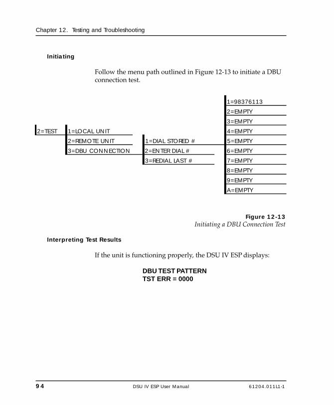
94 DSU IV ESP User Manual 61204.011L1-1
Chapter 12. Testing and Troubleshooting
Initiating
Follow the menu path outlined in Figure 12-13 to initiate a DBUconnection test.
1=98376113
2=EMPTY
3=EMPTY
2=TEST 1=LOCAL UNIT 4=EMPTY
2=REMOTE UNIT 1=DIAL STORED # 5=EMPTY
3=DBU CONNECTION 2=ENTER DIAL # 6=EMPTY
3=REDIAL LAST # 7=EMPTY
8=EMPTY
9=EMPTY
A=EMPTY
Figure 12-13Initiating a DBU Connection Test
Interpreting Test Results
If the unit is functioning properly, the DSU IV ESP displays:
DBU TEST PATTERNTST ERR = 0000

61204.011L1-1 DSU IV ESP User Manual 95
Chapter 13. Activating Dialing Functions
Chapter 13Activating Dial Functions
DIAL OPTIONS
The dial options available from the Main menu (4=Dial) varydepending on the network type selection (3=CONFIG, 1=NET-WORK OPT, 4=NETWORK TYPE). If AT&T/MCI SW56 or USSPRINT SW56 is selected, the options appear as shown in Figure13-1. If DEDICATED is selected and a DBU card is installed, theoptions appear as shown in Figure 13-2.
1=DIAL STORED # Select Stored Number 1-A
4=DIAL 2=ENTER DIAL # NNNNNNN
3=REDIAL LAST #Figure 13-1
Dial Options Menu (SW56)

96 DSU IV ESP User Manual 61204.011L1-1
Chapter 13. Activating Dialing Functions
Answer Unit Connected to DDS Line
1=DIAL BACKUP COMMAND ACCEPTED
Originate Unit Connected to DDS Line
1=DIAL BACKUP 1=DIAL STORED # Select Stored Number 1-A
2=ENTER DIAL # NNNNNNN2=STAY ON LEASED
3=REDIAL LAST #4=DIAL
During Dial Backup
1=HANG UP2=STAY ON LINE
Figure 13-2Dial Options Menu (Dedicated)
Answer Unit Connected to DDS Line
Dial BackupThe message COMMAND ACCEPTED is displayed and theDSU IV ESP waits for an incoming call. When an incoming callis detected, the DSU IV ESP answers the call and enters dialbackup.
Originate Unit Connected to DDS Line
Dial BackupThe DSU IV ESP prompts to dial a stored number or enter anumber to dial for dial backup.
Stay on LeasedThe DSU IV ESP remains on the leased line and does not enterdial backup mode.

61204.011L1-1 DSU IV ESP User Manual 97
Chapter 13. Activating Dialing Functions
Dial Options During Dial Backup
Hang UpTerminates the dial backup connection and attempts to reestab-lish communication on the DDS line.
Stay On LineThis DSU IV ESP remains in dial backup mode and returns to theStatus menu.

98 DSU IV ESP User Manual 61204.011L1-1
Chapter 13. Activating Dialing Functions

61204.011L1-1 DSU IV ESP User Manual 99
Chapter 14. Viewing Status Information
Chapter 14Viewing Status Information
STATUSThe status selection displays two lines of the current operationalstatus of the network and the DTE interfaces.
After 30 seconds of no front panel operation the DSU IV ESPautomatically reverts to the Status display; see Figure 14-1.
1
1
1
1
DTE & LOOP
LOOP 64KDTE 9.6K SYNC
SW56 DBU STATUSOPEN LOOPUNIT IN TESTOPEN LOOP
Test being performed
Network RateDTE Rate/Data FormatDial Backup TypeDial Backup StatusDSU Operational StatusDDS Network Status
This screen only displayed during test.
Figure 14-1Status Display
Network Rate, DTE Rate, and Data Format
This display line (see Figure 14-1) indicates the current loop rateon the first line. The DTE data rate and format (as selected inconfiguration) are shown on the second line.
100 DSU IV ESP User Manual 61204.011L1-1
Chapter 14. Viewing Status Information
Dial Backup Information
Type of Dial Backup ServiceThis display line (see Figure 14-1) indicates the type of dialbackup service installed in the DSU IV ESP. The followingmessages are displayed according to the dial backup optioninstalled in the DSU IV ESP:
ISDN DBU Status 1 B+D Basic Rate ISDN backup optioninstalled.
SW56 DBU Status 4-wire Switched 56 backup optioninstalled.
V.34 DBU Status V.34 backup option installed.
DBU Status No backup service option card installed Not Installed in the DSU IV ESP unit.
Current Status of Dial Backup ModeThis display line (see Figure 14-1) indicates the backup servicestatus. Possible messages include the following:
Answering Call The DSU IV ESP detected an incomingcall message and is initiating call setupprocedure.
Call Disconnect Call disconnect message received fromthe remote end.
Called Unit Busy The unit called is currently busy andcannot be connected (ISDN only).
Dialing The unit is dialing the selected number.

61204.011L1-1 DSU IV ESP User Manual 101
Chapter 14. Viewing Status Information
Going to DBU The DSU IV ESP is entering dial backupmode.
Idle Messages are not being transmitted butthe service is immediately available foruse.
Incoming Call Incoming call messages being received.
In Dial Backup The DSU IV ESP is currently in dialbackup mode.
No RX Signal Sealing current detected but no datasignal received from telco. Also indicatesISDN line is inactive.
No wink from CO Switched 56 provider encountered aservice problem (4-wire SW56 only).
Not Installed No dial backup option installed in theDSU IV ESP.
OOS/OOF From Net Out-of-service signal or out-of-framecondition exists. The call cannot becompleted because the called terminal orthe called terminal's access line is out ofservice or is faulty (4-wire SW56 only).
Open Loop The physical connection to the backupline has been broken (4-wire SW56 only).
DBU Line in RDL Remote end initiated a test.
Test From Telco The network provider has activated theCSU loopback (4-wire SW56 only).
DBU Test Pattern The DSU IV ESP is currently performing atest with a pattern.
Waiting for Call The originating DSU IV ESP is waiting ona call from the remote end.
102 DSU IV ESP User Manual 61204.011L1-1
Chapter 14. Viewing Status Information
Inactive A DBU card is installed but the DSU IVESP is set to SW56 mode.
Getting TEI The ISU card is getting its first terminalendpoint identifier from the network.
Register SPID The ISU card is registering its first SPIDwith the network.
DSU Operation and Network Status
Current DSU IV ESP StatusThis display line (see Figure 14-1) indicates current DSU IV ESPstatus. Possible messages are:
Data Mode In data mode, the data set ready (SR) andrequest to send (RTS) circuits are on, andthe DSU IV ESP is ready to send data.
Unit in Test The DSU IV ESP is currently in test mode;use the Arrows to scroll through themenus to display the type of test beingperformed.
Current DDS Network StatusThis display line (see Figure 14-1) displays the status of the maintelco line. For normal operation this should display LOOP ISNORMAL; other possible messages are described as follows:
Answering Call The DSU IV ESP detects an incoming call.
Check Telco The transmit and receive (Tx/Rx) pairs ofthe loop connection are reversed. Thepairs should be swapped for normaloperation.
Going To DBU This message is displayed briefly whileswitching from the dedicated service todial backup mode.

61204.011L1-1 DSU IV ESP User Manual 103
Chapter 14. Viewing Status Information
In Dial Backup The DSU is in dial backup mode.
LL Test From Telco An LL test has been initiated from thetelco.
Loop is Normal The DSU is connected to the dedicatedline.
OOS/OOF The telco is transmitting an out-of-servicecode.
Open Loop The DDS physical connection has beenbroken.
Waiting for Call The DBU module is waiting for a call.
DTE Control Leads and Status
Four additional DTE interface leads are displayed with theircurrent status (on or off) displayed below. The leads are identi-fied as follows:
TR - Data terminal readySR - Data set readyLLB - Local loopbackRLB - Remote loopback.

104 DSU IV ESP User Manual 61204.011L1-1
Chapter 14. Viewing Status Information

61204.011L1-1 DSU IV ESP User Manual 105
Appendix A. Pinouts
Appendix APinouts
The following tables give the pin assignments for the connectorslocated on the back of the DSU IV ESP, the DBU cards, and theESP ethernet card. For more information on the connectors, seethe chapter Installation.

106 DSU IV ESP User Manual 61204.011L1-1
Appendix A. Pinouts
Table A-APin Assignments for Telco Connector
Pin Name Description1 R1 Transmit Data from DSU to Network-Ring 12 T1 Transmit Data from DSU to Network-Tip 1
3-6 - Not Used7 T Receive Data from Network to DSU-Tip8 R Receive Data from Network to DSU-Ring
Table A-BPin Assignments for ESP DBU Card Connectors
Pin Name Description4-wire Switched 56
1 R1 Transmit Data from DSU to Network-Ring 12 T1 Transmit Data from DSU to Network-Tip 1
3-6 - Not Used7 T Receive Data from Network to DSU-Tip8 R Receive Data from Network to DSU-Ring
V.34 and 1B+D ISDN 1-3 - Not Used
4 T Network-Tip5 R Network-Ring
6 - 8 - Not Used

61204.011L1-1 DSU IV ESP User Manual 107
Appendix A. Pinouts
Table A-CPin Assignments for Primary EIA-232 Connector
Pin EIA Description1 AA Protective Ground (PG)2 BA Transmit Data (SD)3 BB Receive Data (RD)4 CA Request-to-Send (RS)5 CB Clear-to-Send (CS)6 CC Data Set Ready (SR)7 AB Signal Ground (SG)8 CF Received Line Signal Detector (CD)9 - +12 Test Point
10 - -12 Test Point15 DB Transmit Clock (TC)17 DD Receive Clock (RC)18 - Local Loopback (LL)20 CD Data Terminal Ready (TR)21 - Remote Loopback (RL)22 CE Ring Indicator (RI)24 DA External TX Clock (ETC)25 - Test Indicator (TI)

108 DSU IV ESP User Manual 61204.011L1-1
Appendix A. Pinouts
Table A-DPin Assignments for Primary V.35 Connector
Pin CCITT DescriptionA 101 Protective Ground (PG)B 102 Signal Ground (SG)C 105 Request to Send (RTS)D 106 Clear To Send (CTS)E 107 Data Set ReadyF 109 Received Line Signal Detector (CD)H - Data Terminal Ready (DTR)J - Ring Indicator (RI)L - Local Loopback (LL)N - Remote Loopback (RL)R 104 Received Data (RD-A)T 104 Received Data (RD-B)V 115 Receiver Signal Element Timing (SCR-A)X 115 Receiver Signal Element Timing (SCR-B)P 103 Transmitted Data (SD-A)S 103 Transmitted Data (SD-B)Y 114 Transmitter Signal Element Timing (SCT-A)
AA 114 Transmitter Signal Element Timing (SCT-B)U 113 External TX Signal Element (SCX-A)W 113 External TX Signal Element (SCX-B)
NN - Test Indicator (TI)
Table A-EPin Assignments for Control Connector
RJ Pin# Function Direction1 GND2 RTS I3 TD I4 DSR O5 RD O6 CTS* O7 not used not used8 not used not used
*Used for hardware flow control.

61204.011L1-1 DSU IV ESP User Manual 109
Appendix A. Pinouts
Table A-FPin Assignments for 10baseT Connector
Pin Name Description
1 TD+The positive signal for the TD differential pair. This signal contains the serial output data stream transmitted onto the network.
2 TD- The negative signal for the TD differential pair (pins 1 and 2).
3 RD+The positive signal for the RD differential pair. This signal contains the serial input data stream received from the network.
4, 5 N/A not used
6 RD- The negative signal for the RD differential pair (pins 3 and 6).
7, 8 N/A not used

110 DSU IV ESP User Manual 61204.011L1-1
Appendix A. Pinouts

61204.011L1-1 DSU IV ESP User Manual 111
Appendix B. AT Commands
Appendix BAT Commands
Table B-A shows the AT commands available for the DSU IV ESP.
Table B-AAT Commands
Command Title Default
A/ Re-execute Command noneATA Answer noneATDn Dial Number noneATE Echo Command 1ATH Hang Up Call noneATO Go Online noneATQn Result Code Display 0ATSn? Read S-Register noneATSn=x Write to S-Register noneATVn Result Code From Firmware 1ATZ Self Test noneAT&Cn CD Option 0AT&Dn TR Option 0AT&Fn Restore Factory Options noneAT&Ln Network Type 0AT&Pn Remote ConfigurationAT&Qn DTE Data Format 0AT&Rn CS Options 0AT&Sn_Cn SR Options 0
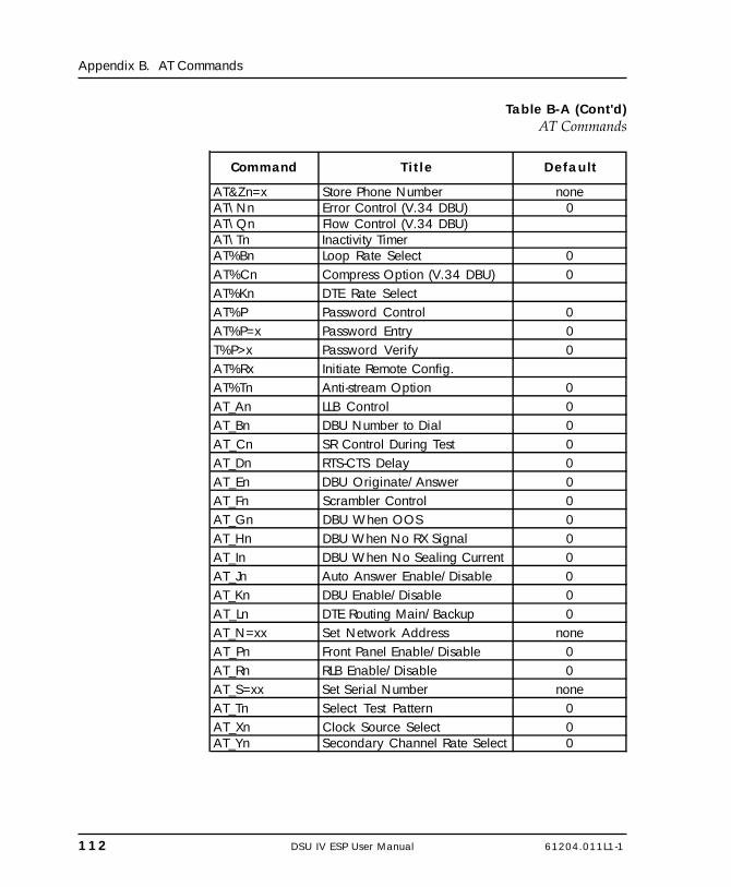
112 DSU IV ESP User Manual 61204.011L1-1
Appendix B. AT Commands
Table B-A (Cont'd)AT Commands
Command Title Default
AT&Zn=x Store Phone Number noneAT\Nn Error Control (V.34 DBU) 0AT\Qn Flow Control (V.34 DBU)AT\Tn Inactivity TimerAT%Bn Loop Rate Select 0AT%Cn Compress Option (V.34 DBU) 0AT%Kn DTE Rate SelectAT%P Password Control 0AT%P=x Password Entry 0T%P>x Password Verify 0AT%Rx Initiate Remote Config.AT%Tn Anti-stream Option 0AT_An LLB Control 0AT_Bn DBU Number to Dial 0AT_Cn SR Control During Test 0AT_Dn RTS-CTS Delay 0AT_En DBU Originate/Answer 0AT_Fn Scrambler Control 0AT_Gn DBU When OOS 0AT_Hn DBU When No RX Signal 0AT_In DBU When No Sealing Current 0AT_Jn Auto Answer Enable/Disable 0AT_Kn DBU Enable/Disable 0AT_Ln DTE Routing Main/Backup 0AT_N=xx Set Network Address noneAT_Pn Front Panel Enable/Disable 0AT_Rn RLB Enable/Disable 0AT_S=xx Set Serial Number noneAT_Tn Select Test Pattern 0AT_Xn Clock Source Select 0AT_Yn Secondary Channel Rate Select 0

61204.011L1-1 DSU IV ESP User Manual 113
Appendix C. Terminal Menu Structure
Appendix CTerminal Menu Structure
This appendix describes the terminal menus used when manag-ing the DSU IV ESP through either a VT 100 terminal interface ora TELNET session. Examples of the terminal screens as well as amenu tree (Figure C-2) are provided.
Due to the increased display capabilities, the VT 100 menu structurediffers from the front panel interface. Descriptions of individual menuoptions are provided throughout this manual based on the front panelmenu structure. See Figure 5-1 for the front panel configuration menutree.

114 DSU IV ESP User Manual 61204.011L1-1
Appendix C. Terminal Menu Structure
TERMINAL INTERFACE MAIN MENU
The terminal Main menu is the opening menu to all operationsof the DSU IV. Select one of the choices by pressing the corre-sponding number; then press Enter. See Figure C-1.
The Dial selection in the terminal Main menu is determined by twothings: the Network Type selected in the Configuration menu and thepresence/absence of a DBU card. See Table C-A.
Table C-ATerminal Main Menu Dial Selection
Network Type Selected DBU Card Sixth Selection
DEDICATED installed DIAL ESP DBUSW56 N/A DIAL SW56
DEDICATED not installed no selection available
Figure C-1Terminal Interface Main Menu (SW56 Network Type Selected)
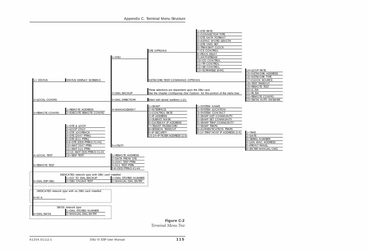
61204.011L1-1 DSU IV ESP User Manual 115
Appendix C. Terminal Menu Structure
Figure C-2Terminal Menu Tree
1=DTE RATE2=CONNECTOR TYPE3=DTE DATA FORMAT4=ASYNC WORD LENGTH5=DTE CMD SET6=TRANSMIT CLOCK
DTE OPTIONS 7=CS CONTROL8=RS-CS DELAY
1=DSU 9=ANTI-STREAM10=CD CONTROL11=TR CONTROL12=SR CONTROL13=SCRAMBLE (64K) 14=LOOP RATE
15=NETWORK ADDRESS16=NETWORK TYPE
1= STATUS STATUS DISPLAY SCREENS NETWORK/TEST/COMMAND OPTIONS 17=CLOCK SOURCE18=TEST TIMEOUT19=REMOTE TEST
These selections are dependent upon the DBU card. 20=LL EIA2=DIAL BACKUP See the chapter Configuring Dial Options for this portion of the menu tree. 21=RL EIA
22=REMOTE CONFIG2=LOCAL CONFIG 3=DIAL DIRECTORY Enter/edit stored numbers 1-10. 23=SW56 AUTO ANSWER
1=SNMP 1=SYSTEM NAME1=REMOTE ADDRESS 4=MANAGEMENT 2=INTERFACE 2=SYSTEM LOCATION
3=REMOTE CONFIG 2=EXECUTE REMOTE CONFIG 3=CONTROL RATE 3=SYSTEM CONTACT4=IP ADDRESS 4=SNMP GET COMMUNITY5=SUBNET MASK 5=SNMP SET COMMUNITY6=GATEWAY IP ADDRESS 6=SNMP TRAP COMMUNITY
1=DTE & LOOP 7=TELNET PASSWORD 7=SNMP TRAPS2=LOOP ONLY 8=SESSION TIMEOUT 8=AUTHENTICATION TRAPS3=DTE LOOPBACK 9=IP SECURITY 9-13=TRAP HOST IP ADDRESS (1-5) 1=TIME4=DTE (2047 PTRN) 10-14=IP FILTER ADDRESS (1-5) 2=DATE5=DTE (511 PTRN) 3=SERIAL NUMBER6-9=DTE (DDS PTRNS #1-#4) 4=LAN MAC ADDRESS10=XMIT 2047 PTRN 5=UTILITY 5=FRONT PANEL11=XMIT 511 PTRN 6=ENTER MANUAL CMD12-15 XMIT DDS PTRNS #1-#4
4=LOCAL TEST 16=SELF TEST 1=REMOTE ADDRESS2=DATA FROM DTE3=2047 TEST PTRN
5=REMOTE TEST 4=511 TEST PTRN5-8=DDS PTRNS #1-#4
DEDICATED network type with DBU card installed1=GO TO DIAL BACKUP 1=DIAL STORED NUMBER
6=DIAL ESP DBU 2=DBU ONLINE TEST 2=MANUAL DIAL ENTRY
DEDICATED network type with no DBU card installed
6=N/A
SW56 network type1=DIAL STORED NUMBER
6=DIAL SW56 2=MANUAL DIAL ENTRY

116 DSU IV ESP User Manual 61204.011L1-1
Appendix C. Terminal Menu Structure

61204.011L1-1 DSU IV ESP User Manual 117
Appendix C. Terminal Menu Structure
Status Menus
Status menus display all relevant information for the networkand DTE interfaces. For more information, see the chapterViewing Status Information. See Figure C-3.
Figure C-3Status Menu

118 DSU IV ESP User Manual 61204.011L1-1
Appendix C. Terminal Menu Structure
Local/Remote Configuration Menus
When Local Configuration is selected, the screen in Figure C-5appears. For Remote Configuration, the remote address must beentered through the menu shown in Figure C-4. After enteringthe address, the menu in Figure C-5 appears.
Figure C-4Remote Configuration Options

61204.011L1-1 DSU IV ESP User Manual 119
Appendix C. Terminal Menu Structure
Menu
Figure C-5Main Configuration Menu

120 DSU IV ESP User Manual 61204.011L1-1
Appendix C. Terminal Menu Structure
DSU Configuration (DTE, Network, and Test options)
The chapters Configuring Network Options, Configuring DTEOptions, Configuring Test Options, and Configuring Dial Optionsinclude detailed descriptions of these parameters. See FigureC-6.
Figure C-6DSU Configuration Menu
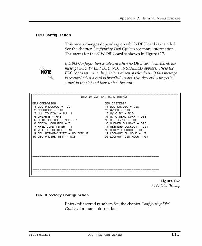
61204.011L1-1 DSU IV ESP User Manual 121
Appendix C. Terminal Menu Structure
DBU Configuration
This menu changes depending on which DBU card is installed.See the chapter Configuring Dial Options for more information.The menu for the S4W DBU card is shown in Figure C-7.
If DBU Configuration is selected when no DBU card is installed, themessage DSU IV ESP DBU NOT INSTALLED appears. Press theESC key to return to the previous screen of selections. If this messageis received when a card is installed, ensure that the card is properlyseated in the slot and then restart the unit.
Figure C-7S4W Dial Backup
Dial Directory Configuration
Enter/edit stored numbers See the chapter Configuring DialOptions for more information.

122 DSU IV ESP User Manual 61204.011L1-1
Appendix C. Terminal Menu Structure
Management Configuration
Select the management interface and set the unit up to respondto the selected interface. See the chapter Configuring ManagementFunctions for more information. The Management menu isshown in Figure C-8. The SNMP menu which branches from theManagement menu is shown in Figure C-9.
Figure C-8Management Menu
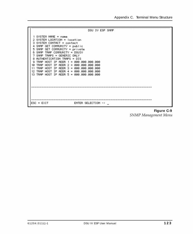
61204.011L1-1 DSU IV ESP User Manual 123
Appendix C. Terminal Menu Structure
Figure C-9SNMP Management Menu
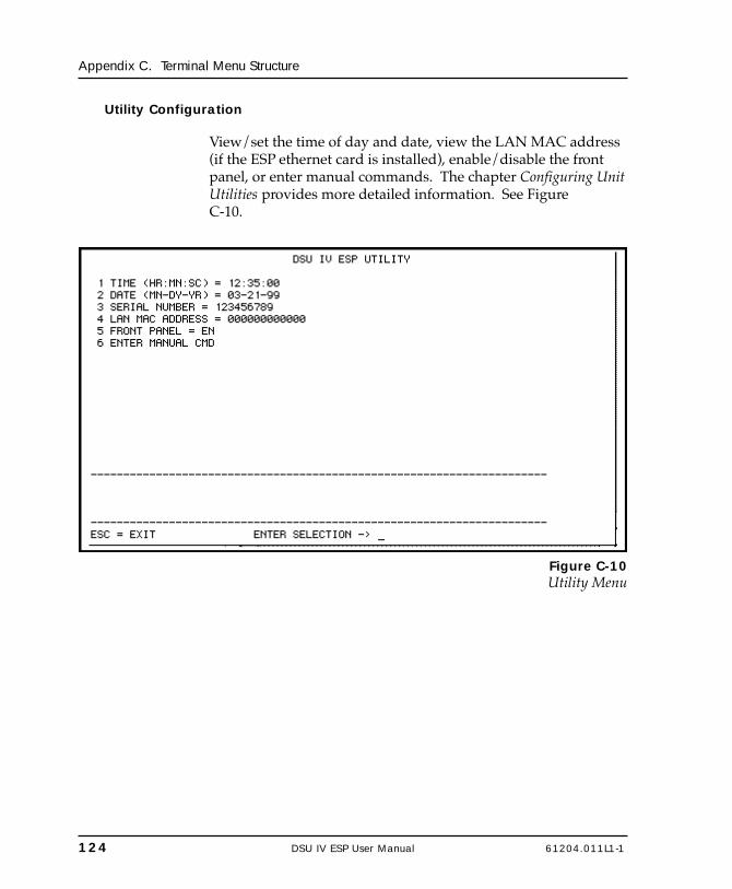
124 DSU IV ESP User Manual 61204.011L1-1
Appendix C. Terminal Menu Structure
Utility Configuration
View/set the time of day and date, view the LAN MAC address(if the ESP ethernet card is installed), enable/disable the frontpanel, or enter manual commands. The chapter Configuring UnitUtilities provides more detailed information. See FigureC-10.
Figure C-10Utility Menu
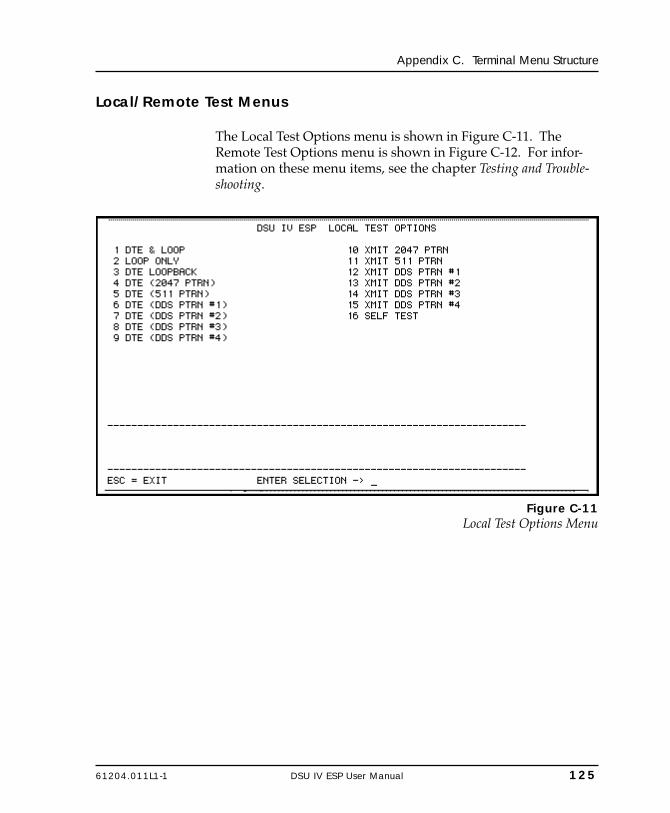
61204.011L1-1 DSU IV ESP User Manual 125
Appendix C. Terminal Menu Structure
Local/Remote Test Menus
The Local Test Options menu is shown in Figure C-11. TheRemote Test Options menu is shown in Figure C-12. For infor-mation on these menu items, see the chapter Testing and Trouble-shooting.
Figure C-11Local Test Options Menu

126 DSU IV ESP User Manual 61204.011L1-1
Appendix C. Terminal Menu Structure
Figure C-12Remote Test Options Menu

61204.011L1-1 DSU IV ESP User Manual 127
Appendix C. Terminal Menu Structure
Dial SW56/Dial ESP DBU
When in SW56 mode (SW56 Network Type selected), the DialSW56 selection is shown in the Terminal Interface Main menu(see Figure C-1 and Table C-A). When a DBU ESP card isinstalled and the DEDICATED Network Type is selected, theDial ESP DBU selection is shown instead.
Dial SW56 Options
This menu (see Figure C-13) is available when operating in SW56mode. Choose to dial a stored number or enter a numbermanually.
Figure C-13SW56 Dialing Menu

128 DSU IV ESP User Manual 61204.011L1-1
Appendix C. Terminal Menu Structure
Dial ESP DBU
This menu is available when an ESP option card is installed inthe DSU IV ESP and the Network Type is set to DEDICATED.See the chapter Activating Dial Functions for more information onindividual menu selections.
Figure C-14Dial ESP DBU Menu
61204.011L1-1 DSU IV ESP User Manual 129
Appendix D. Configuration Profiles
Appendix DConfiguration Profiles
The DSU IV ESP contains four different user profiles (sets ofconfigurations options) stored in read-only memory; see TableD-A. The unit is shipped from the factory with profile 1 loadedinto the nonvolatile configuration memory. See the sectionManual Command of the Utilities chapter for more information onentering the manual commands required to load these profiles.
Profile 1Profile 1 is configured for a 56 kbps, synchronous, point-to-pointor dial-up operation with a V.35 connector. Automatic DBU hasbeen disabled for this configuration profile.
Profile 2Use profile 2 for a 56 kbps, asynchronous, point-to-point or dial-up operation, with an EIA-232 connector. Automatic DBU hasbeen disabled for this configuration profile.
Profiles 3 and 4Profiles 3 and 4 are identical to profile 1 with the addition of dialbackup capability. These profiles are used for enabling dialbackup using two DSU IV ESP units. One unit must be set forAnswer and the other for Originate. Use profile 3 to set theremote unit to Answer and profile 4 to set the host unit toOriginate.

130 DSU IV ESP User Manual 61204.011L1-1
Appendix D. Configuration Profiles
Table D-AConfiguration Profiles
Profile Numbers(00) 1 (01) 2 (02) 3 (03) 4
Manual CommandEscape Character 43=2BH 43=2BH 43=2BH 43=2BHCR Character 13=0DH 13=0DH 13=0DH 13=0DHLF Character 10=0AH 10=0AH 10=0AH 10=0AHBS Character 8 8 8 8DBU Abort Call Timer 50=32H 50=32H 50=32H 50=32HEscape Guard Timer 50=32H 50=32H 50=32H 50=32HCommand Echo Enable Enable Enable EnableResult Code Enable Enable Enable EnableLong or Short Code Long Long Long LongTest Pattern Type 2047 2047 2047 2047CS Delay Short Short Short ShortDTR Recog. Delay (x100ms) 3 3 3 3DTR Command Timeout (x100)
8 8 8 8
Front Panel En/Dis Enable Enable Enable EnableInactivity Timer Off Off Off OffAT Password Control Disable Disable Disable DisableNetwork OptionsLoop Rate AUTO AUTO AUTO AUTONetwork Address 0 0 0 0Remote Conf. En/Dis Enable Enable Enable EnableClock Source From Network From Network From Network From NetworkDTE OptionsRemote DSU Address 0 0 0 0DTE Rate (56k loop) 56k/57.6k 56k/57.6k 56k/57.6k 56k/57.6kScrambler Mode OFF OFF OFF OFFConnector Type V.35 RS232 V.35 V.35DTE Data Format SYNC ASYNC SYNC SYNCDTE Command Options DIS DIS DIS DISTransmit Clock Normal Normal Normal NormalCS Options Follow RS Follow RS Follow RS Follow RSAnti-stream Timer Timer Off Timer Off Timer Off Timer OffCD Option Normal Normal Normal NormalTR Options Ignored Ignored Ignored IgnoredSR Options Off Test+OOS Off Test+OOS Off Test+OOS Off Test+OOSSecondary Channel Rate OFF OFF OFF OFF

61204.011L1-1 DSU IV ESP User Manual 131
Appendix D. Configuration Profiles
Table D-A (Cont'd) Configuration Profiles
Profile Numbers(00) 1 (01) 2 (02) 3 (03) 4
Test OptionsTest Timeout Off Off Off OffRDL En/Dis RDL Accepted RDL Accepted RDL Accepted RDL AcceptedEIA Controlled LLB Disable Disable Disable DisableEIA Controlled RLB Disable Disable Disable DisableDBU Answer Test Disable Disable Disable DisableDial OptionsAutomatic DBU Disable Disable Enable EnableDBU Number to Dial #1 #1 #1 #1DBU Originate/Answer Answer Answer Answer OriginateDBU when OOS Enable Enable Enable EnableDBU when No RX Signal Enable Enable Enable EnableDBU when No Sealing Current Enable Enable Enable EnableDBU Auto Restore Timer 1 minute 1 minute 1 minute 1 minuteDBU Redial Counter 5 5 5 5DBU Fail-Timer (x10 seconds) 3 3 3 3DBU Redial Wait Time 10 10 10 10When all 1s/0s Disable Disable Disable DisableNetwork Type AT&T AT&T AT&T AT&TError Control Auto
V.42/MNPAuto
V.42/MNPAuto
V.42/MNPAuto
V.42/MNPFlow Control (V.32) CTS Only CTS Only CTS Only CTS OnlyData Compression (V.32) Enabled Enabled Enabled Enabled

132 DSU IV ESP User Manual 61204.011L1-1
Appendix D. Configuration Profiles

61204.011L1-1 DSU IV ESP User Manual 133
Appendix E. DSU to Modem Interconnect
Appendix EDSU to Modem Interconnect
MODEM TAIL CIRCUIT APPLICATION
A DSU to modem interconnect diagram for a modem tail circuitapplication is shown in Figure E-1.
MODEM
DSU
IV
RC
ETC
RD
TD
DCD
RTS
ETC
RC
TD
RD
RTS
DCD
For Multi-drop requirement:
Figure E-1DSU to Modem Interconnect

134 DSU IV ESP User Manual 61204.011L1-1
Appendix E. DSU to Modem Interconnect
61204.011L1-1 DSU IV ESP User Manual 135
Appendix F. Specifications Summary
Appendix FSpecifications Summary
This section describes the standard specifications and featuresincorporated in the DSU IV ESP.
Operating Modes• Dedicated DDS (point-to-point, multi-point)• Switched 56 (4-wire)• ISDN (1B+D)• PSTN (V.34)
Network Data Rates• Dedicated mode service rates: 2.4, 4.8, 9.6, 19.2, 38.4, 56, and 64
kbps.• Switched mode service rate: 56 kbps.• Dial Backup:
Switched 56 (56 kbps)V.34 (2.4 - 33.6 kbps)ISDN (56 or 64 kbps)
DTE Rates Provided• DTE rates match service rates• DTE-to-loop rate matching in both dedicated and switched
modes• Synchronous rates: 2.4, 4.8, 9.6, 19.2, 38.4, 56, and 64 kbps• Asynchronous rates: 2.4, 4.8, 9.6, 19.2, 38.4, and 57.6 kbps
DTE InterfacesBoth EIA-232 and V.35 electrical and physical DTE interfaces

136 DSU IV ESP User Manual 61204.011L1-1
Appendix F. Specifications Summary
SNMP and TELNET• Integrated SLIP/PPP port• Physical Connector RJ-48S and DB-25• Optional 10baseT interface with ESP Ethernet Card• MIB II RFC 1213 complaint• Enterprise-specific MIB• SNMP traps
Clocking• Normal DDS (slaved to network receive clock)• Private network master (internal)• Normal DDS tail circuit• Private network master (slaved to external clock)
Switched Mode Dialing Options• Stored number• Front panel keypad• DTR dialing of stored numbers• In-band AT commands• V.25 bis in-band dialing
Diagnostics• Network : CSU and DSU loopbacks• User : Local DTE and loop, remote V.54• Test Patterns : 2047, 511, DDS stress patterns 1-4
Line RequirementsLoop transmission parameters as defined in:
AT&T PUB 62310: Dedicated DDSAT&T PUB 4146B: Switched 56Sprint TS 0046: Switched 56
Line InterfaceRJ-48S, 4-wire, full duplex
Receiver Sensitivity-45 dB at all rates
61204.011L1-1 DSU IV ESP User Manual 137
Appendix F. Specifications Summary
Agency ApprovalsU.L. 1950C-U.L. 1950FCC Part 15, Class AFCC Part 68CS03
EnvironmentOperating Temperature: 0 to 50 OC (32 to 122 OF)Storage Temperature: -20 to 70 OC (-4 to 158 OF)Relative Humidity: Up to 95%, non-condensing
Hardware SpecificationsDimensions: 10.4”D x 8.0”W x 2.4”HWeight: 4.5 lbs.Power: 115V ac, 75 mA max
8.6 watts
138 DSU IV ESP User Manual 61204.011L1-1
Appendix F. Specifications Summary

61204.011L1-1 DSU IV ESP User Manual 139
Glossary
Glossary10baseT
Ethernet IEEE standard on 24 gauge unshielded twisted pair wiring, a basebandmedium, at 10 megabits per second.
2047A pseudorandom test pattern that is repeated every 2047 bits; used to test DSU/CSUs.
4-Wire Switched 56An AT&T proprietary 56/64 kbps switched digital data service offered by telcoservice providers and delivered to users over four copper wires.
511A pseudorandom test pattern that is repeated every 511 bits; used to test DSU/CSUs.
agentThe implementation of a network management protocol which exchangesnetwork management information with a network management station.
asynchronousA method of data transmission which allows characters to be sent at irregularintervals by preceding each character with a start bit, followed by a stop bit.
AT&T Publication 41458An AT&T specification titled "Special Access Connections to the AT&TCommunications Network," used to design compatibility into DSU/CSUproducts.
140 DSU IV ESP User Manual 61204.011L1-1
Glossary
AT&T Publication 62310An AT&T specification titled "Digital Data System Channel InterfaceSpecification," used to design compatibility in DSU/CSU products.
BERTbit error rate test. A known pattern of bits is transmitted and the errors receivedare counted to figure the bit error rate. The idea is to measure the quality of datatransmission. The bit error rate is the ratio of received bits that are in error,relative to the number of bits received. Usually expressed in a power of 10.
CDcarrier detect. A signal generated by a modem or DSU/CSU. CD indicates itsconnection status. If the CD light is on, the device is speaking to another device.
clockingAn oscillator-generated signal that provides a timing reference for a transmissionlink. A clock provides signals used in a transmission system to control the timingof certain functions. The clock has two functions: (1) to generate periodic signalsfor synchronization and (2) to provide a time base.
control portAn interface to a device or system that allows users to issue commandspertaining to dialing, configuration, diagnostics, management, etc.
CPEcustomer premise equipment. All telecommunications terminal equipmentlocated on the customer premises, including telephone sets, private branchexchanges (PBXs), data terminals, and customer-owned coin-operatedtelephones.
CSSee CTS.
CSUchannel service unit. A DCE device used to connect a digital phone line (T1 orSwitched 56 line) coming in from the phone company to either a multiplexer, achannel bank, or directly to another device producing a digital signal (forexample a digital PBX, a PC, or data communications device). A CSU performscertain line-conditioning and equalization functions, and responds to loopback

61204.011L1-1 DSU IV ESP User Manual 141
Glossary
commands sent from the central office. A CSU regenerates digital signals. Itmonitors them for problems, and provides a way of testing the digital circuit.
CSU loopbackA telco initiated test which loops the CSU portion of the DSU/CSU back to thetelco and allows the telco to test the DDS circuit as well as the CSU portion of thecustomer's DSU/CSU.
CTSclear to send. A signal on the DTE interface indicating that the DCE is clear tosend data. Sometimes referred to as CS.
dBdecibel. A unit of measure of signal strength, usually the relation between atransmitted signal and a standard signal source.
DCEdata communications equipment. Device that provides all the functions requiredfor connection to telephone company lines and for converting signals betweentelephone lines and DTE.
DDSdataphone digital service also called digital data system. A private line digitalservice for transmitting data end-to-end at speeds of 2.4, 4.8, 9.6, and 56 kbps andin some cases 19.2, 38.4, or 64 kbps. The systems can use central hub offices forobtaining test access, bridging legs of multipoint circuits, and cross connectingequipment. DDS is offered on an inter-LATA basis by AT&T and on an intra-LATA basis by the Bell operating companies.
DDS Stress Patterns 1-4A series of test patterns designed to test DDS circuits. Each pattern is designed tostress the DDS circuit in a particular manner to assure its reliability.
DSUdata service unit. A device designed to transmit and receive digital data ondigital transmission facilities.
DSU loopbackA telco initiated test which loops the DSU back to the telco and is used to test theDDS circuit as well as the DSU/CSU.
142 DSU IV ESP User Manual 61204.011L1-1
Glossary
DTEdata terminal equipment. In the EIA-232 standard specification, the EIA-232 isconnected between the DCE and a DTE. The main difference between the DCEand the DTE is that pins two and three are reversed.
DTE to loop rate matchingA feature designed into ADTRAN DSU/CSU products that allows slower DTEdevices to communicate over 56/64 kbps digital circuits.
DTRdata terminal ready. A control signal sent from the DTE to the DCE that indicatesthe DTE is powered on and ready to communicate. DTR dialing allows a DSU/CSU to dial a predetermined number when DTR goes high.
EIA-232A set of standards specifying various electrical and mechanical characteristics forinterfaces between computers, terminals, and modems. Defines the mechanicaland electrical characteristics for connecting DTE and DCE data communicationsdevices. It defines what the interface does, circuit functions, and theircorresponding connector pin assignments. The standard applies to bothsynchronous and asynchronous binary data transmission.
FCC Part 15 of Class ARadiated and conducted emissions standards set for commercial and industrialuse.
FCC Part 15 of Class BRadiated and conducted emissions standards set for residential use.
FCC Part 68FCC rules and regulations intended to provide protection of the telephonenetwork from harm caused by connection of equipment to the network.
in-bandSignaling (dialing, diagnostics, management, configuration, etc.) over the samechannel used for data.
IPA connectionless-mode network service protocol.

61204.011L1-1 DSU IV ESP User Manual 143
Glossary
ISDNintegrated services digital network. A network architecture that enables end-to-end digital connections. The network supports diverse services throughintegrated access arrangements and defines a limited set of standard,multipurpose interfaces for equipment vendors, network providers, andcustomers. Interworking with a public switched telephone network is retained.
LANA privately owned network that offers high-speed communications channels toconnect information processing equipment in a limited geographic area.
local DTE and loop testA test initiated by the user that loops the DSU to the central office and back. Thisis used to test the local DSU's DTE and local loop.
multidropA communications arrangement in which multiple devices share a commontransmission channel, although only one may transmit at a time.
out-of-bandSignaling that is separated from the channel carrying information (voice, data,video, etc.). Typically the separation is accomplished by a filter. The signalingincludes dialing and other supervisory signals.
point-to-point A private circuit, conversation, or teleconference in which there is one person ateach end, usually connected by some dedicated transmission modem.
private network master clockingClocking in which timing is derived internally from the DSU.
private network tributary clockingClocking in which the timing is derived from the DDS loop.
private network master - slaved to external clockClocking in which timing is slaved to the DSU's external transmit clock.
protocolA set of rules governing transfer of data.

144 DSU IV ESP User Manual 61204.011L1-1
Glossary
PSTNpublic switched telephone network. A direct distance dialing telephone networkthat is available for public use. The network is an integrated system oftransmission and switching facilities, signaling processors, and associatedoperations support systems that is shared by customers. PSTN also is calledpublic network, public switched network, or public telephone network.
RDLremote digital loopback.
remote configurationA feature designed into ADTRAN DSU/CSU products that allow a remote DSU/CSU to be configured from a local DSU/CSU or VT 100 compatible terminal.
remote V.54 testA diagnostic feature that allows testing of the DDS circuit by looping the remoteDSU/CSU back to the local DSU/CSU.
RJ-45registered jack. 8-pin connector used for data transmission over standardtelephone wire. Single line, 2-wire T/R, PR/PC, programmed data, 8 position,keyed.
routerA device that supports LAN-to-LAN communications.
scramblerA device that transposes or inverts signals, or otherwise encodes a message atthe transmitter, to make it unintelligible at a receiver not equipped with anappropriately set descrambling device.
SDLCsynchronous data link control. A link-level communications protocol used in aninternational business machines (IBM) systems network architecture (SNA)network that manages synchronous, code-transparent, serial information transferover a link connection. SDLC is a subset of the HDLC protocol developed byISO.

61204.011L1-1 DSU IV ESP User Manual 145
Glossary
sealing currentA 4 to 20 mA direct current used by OCU DPs to reduce corrosion in the wiresand to verify the connection of a device on the loop.
serviceThe provision of telecommunications to customers by a common carrier,administration, or private operating agency, using voice, data, and/or videotechnologies.
SNMPsimple network management protocol. A control and reporting scheme widelyused to manage devices from different vendors. SNMP operates on top of theinternet protocol.
SRdata set ready. A signal on the EIA-232 interface that indicates if communicationis connected and ready to start handshaking control signals so communicationcan begin.
switchedIn regards to DSU/CSUs, the ability to perform the functions of establishing andreleasing connections on a per call basis between two or more circuits, services orcommunications systems. The DSU III S2W and DSU III S4W are examples ofSwitched 56 DSU/CSUs.
synchronousCommunications in which the timing is achieved by sharing a single clock. Eachend of the transmission synchronizes itself with the use of clocks andinformation sent along with the transmitted data.
tail circuitA feeder circuit, which may be digital or analog, that provides an access line to adigital or analog network.
TCPtransport control protocol. The transport protocol offering a connection-orientedtransport service in the internet suite of protocols.
trapAn unsolicited message issued by a network device to report an operationalanomaly or an alarm condition.
146 DSU IV ESP User Manual 61204.011L1-1
Glossary
U interfaceA twisted-pair subscriber loop carrying an ISDN 160 kbps digital signal betweenthe ISDN central office and the NT1 at the customer premises.
ULUnderwriters Laboratories. A laboratory established by the National Board ofFire Underwriters that tests equipment, materials, and systems that may affectinsurance risks, with special reference to fire dangers and other hazards to life.
UL 1459A UL rating that assures the connected equipment (DSU/CSU) providesprotection from current overloads and power line crosses.
V.25 bisAutomatic calling and answering command set including the ability to workwith async, bisync and HDLC devices. Provides a small subset of the functionsof the Hayes® Standard AT Command Set.
V.34Latest high-speed standard for full-duplex transmission on two-wire leased anddial-up lines at the following rates: 2.4, 4.8, 7.2, 9.6, 12, 14.4, 16.8, 19.2, 21.6, 24,26.4, and 28.8 kbps without compression. The maximum connection ratebetween two V.34 modems is 28.8 kbps. Occasionally, connections occur at 26.4,24, and 21.6 kbps because line quality differs from one call to the next.
V.FC (V. Fast Class)Proprietary modulation scheme developed by Rockwell International for datacommunication speeds up to 28.8 kbps.
VT 100A non-intelligent terminal or terminal emulation mode used for asynchronouscommunications.
WANwide area network. Any one of a number of technologies providinggeographically distant transfer.
61204.011L1-1 DSU IV ESP User Manual 147
Index
IndexSymbols
10baseT 13910baseT connector 8, 23
pin assignments 1091B+D ISDN 21s/0s 572047 1394-wire SW56 1394-wire SW56 DBU card 24-wire switched 56 1, 5511 139
A
agent 4, 139alarm LED 14all 1s or all 0s condition 27, 57ALM 14answer
AT command 56call 100, 102
answer always 57anti-stream 47–48applications 23
dial backup 26LAN with SNMP/TELNET 23
arrows 14async PPP 1, 8, 11asynchronous 139AT commands 29, 33, 75, 111, 112
phone number 55AT&T 5ESS 64
AT&T Publication 41458 139AT&T Publication 62310 140auto answer 56auto DBU fail 59auto restore 58automatic DBU 56
B
BERT 140
C
call disconnect 100called unit busy
status message 100cancel key 14cards (options) 10
installation 10carrier detect 140carrier detect (CD) 14, 48CD 14, 48, 140check telco 102clear to send 141clear to send (CS) 14, 47clock source 40clocking 136, 140compression 62Config 17configuration 17, 19
dial options 53–64DTE options 41local 36

148 DSU IV ESP User Manual 61204.011L1-1
Index
management 65methods 29network options 37overview 29test options 49–51utilities 71
configuration menusterminal 118
configuration profiles 129configuration remote 36connector type 46control
port 20control connector
pin assignments 108control port 1, 9, 11, 23, 140control rate 66CPE 140CS 14, 47, 140CSU 140CSU loopback 141CTS 140, 141customer premise equipment 140customer service 6, 7
D
daily lockout 58data communications equipment 141data format 46, 99data mode
status message 102data service unit 141data set ready (SR) 48, 103data terminal equipment 142data terminal ready (TR) 48, 103dB 141DBU
AT commandsall models 60, 61V.34 card 63
DBU answer test 51DBU card
pin assignments 106DBU cards 5
DBU configuration 121DBU connection 93DBU criteria 57DBU interface 9DBU line in RDL 101DBU lockout options 1DBU operation 5DBU options
all models 56ISDN card 64S4W card 62V.34 card 62–63
DBU passcode 64DBU status 100DBU test pattern
status message 101DCE 141DDS 1, 26, 28, 40, 141DDS rates 1DDS circuit
returning to 28DDS network status 102DDS operation 3DDS stress patterns 1-4 141diagnostics 136dial 19dial backup 1, 96
ISDN 55mode
entering 26status 100
status information 100dial directory 121dial functions
activating 95–97dial operations 127dial options
configuration 53–64menu tree 54–64
dedicated network type 96–97SW56 network type 95–97
dial up operation 129dialing 100dialing options 136down arrow 14

61204.011L1-1 DSU IV ESP User Manual 149
Index
DSU 141DSU configuration
terminal 120DSU loopback 141DSU status 102DSU to modem interconnect 133DTE 1, 142
primary 10DTE & loop (LL) 84DTE command option 46DTE connectors 9DTE control leads 103DTE interface 9, 135DTE only 86DTE options 41
AT commands 43, 44, 45menu tree 42
DTE rate 45, 99, 135same as the network 45
DTE status 103DTE to loop rate matching 142DTR 142
E
EIA local loopback (LLB) 51EIA remote loopback (RLB) 51EIA-232 2, 9, 10, 142EIA-232 connector
pin assignments 107enter key 13environment 137error control 62ethernet 1, 8, 23exit test 77external clock 46
F
fail timer 58FCC Part 15 of Class A 142FCC Part 15 of Class B 142FCC Part 68 142flow control 62
front panel 13alpha entry 69illustration/functions 15operation 17
front panel commands 29
G
gateway IP address 25, 66Get community 67getting TEI
status message 102glossary 139going to DBU 101, 102
H
hang up 97
I
idle 101in dial backup 101, 103in-band 142inactive
status message 102included in shipment 7, 8incoming call 101installation 7–11interface 25, 66INV 35INVBL 35INVBM 35INVCU 35invert clock 47INVPS 35INVPV 35IP 142IP address 25, 66IP filter address 66IP security 66ISDN 1, 6, 55, 143
DBU options 64DBU status 100dial backup 55

150 DSU IV ESP User Manual 61204.011L1-1
Index
K
keypad 13
L
LAN 5, 23, 29, 143LAN interface 9LAN MAC address
viewing 74LCD window 13LED
description 14line interface 136line requirements 136LL test from telco 103LOC 55local DTE and loop test 143local loopback 75, 103local unit
test 82lockout
weekend/time of day 28lockout end 58lockout start 58loop is normal 102, 103loop only (RT) 85loop rate 39loss of sealing current 27
M
main menu 77front panel 18
management configuration 122management functions 65–69
menu tree 65–69manual commands 72
entering 72list of 73
menu itemsselecting 13
menu navigation 17menu structure
front panel 18VT 100 20
MIB 4, 23, 68modem tail circuit
application 133multidrop 143
N
national ISDN1 64network address 40network data rates 135network manager 4network options 37–40
AT commands 38–40menu tree 39–40
network rate 99network status 102network type 40, 62no DBU installed - DBU status 100no receive (RX) signal 27, 57, 101no sealing current 57no wink from CO 101not installed 101NT DMS-100 64number to dial 56
O
OOS/OOF from net 101OOS/OOF from telco 103open loop 101, 103operating modes 135operation 13–21, 75–94
during critical times 27during noncritical times 28
originate 56originate/answer 56out of service (OOS) 57
signal 27out-of-band 143
P
password 20phone number 55
AT command 55

61204.011L1-1 DSU IV ESP User Manual 151
Index
pin assignments10baseT connector 109control connector 108ESP DBU card connector 106primary EIA-232 connector 107primary V.35 connector 108telco connector 106
pinouts 105point-to-point 143point-to-point operation 129power cord 9power switch 9power up 8PPP 1private network master
slaved to external clock 143product overview 1protocol 143PSTN 144
R
RD 14RDL 50, 144rear panel 9receipt inspection 7receive (RX) signal 57receive data 14receiver sensitivity 136redial counter 58register SPID
status message 102remote command 11remote configuration 40, 118, 144remote digital loopback (RDL) 50remote loopback 75, 103remote V.54 test 144request to send (RS) 14restore timer 58return material authorization (RMA) 6RJ-45 144router 144RS 14RS to CS delay 47
S
scrambler 45, 144SDLC 144sealing current 57, 145secondary channel
connection 11services 9
self test 90service 145Set community 67SHIFT key 13, 17SLIP 1, 8, 11, 23SLIP/PPP 29SNMP
1, 4, 8, 11, 23, 25, 123, 136, 145configuring options 67ethernet LAN application 24network manager 23SLIP/PPP LAN application 24
SNMP accessconfiguring for 25
SNMP traps 67SNMP/TELNET management
application 23software revision
viewing 74specifications 135SPID 55SR 48, 145status 18, 99
DDS network 102dial backup mode 100
status menusterminal 117
stay on leased 96stay on line 97subnet mask 25, 66SW56 1SW56 DBU status 100switch type 64switched 145synchronous 145synchronous operation 75system contact 68

152 DSU IV ESP User Manual 61204.011L1-1
Index
system location 68system name 68
T
tail circuit 145TCP 145TD 14telco 9telco connector 10
pin assignments 106telco jack 9TELNET 1, 20, 23, 25, 113, 136
configuring for 25ethernet LAN application 24SLIP/PPP LAN application 24
TELNET options 68TELNET password 68TELNET timeout 68terminal
connection/operation 20terminal menu structure 113test 18, 103
DTE only 86loop only 85self 90test pattern 89
test commands 82test from telco 101test menu 78test menus 125test mode manual 14test options 125
AT commands 50–51configuration 49–51menu tree 49–51
test pattern 89test timeout 50time/date
viewing/editing 74TR 48transmit clock 46transmit data 14trap 145Trap community 67
trap IP address 67
U
U interface 146UL 146UL 1459 146unit in test
status message 102up arrow 14utilities 71
menu tree 71utility configuration 124
V
V.25 bis commands 29, 34, 75, 146asynchronous option 35bi-sync option 34SDLC option 34
V.34 1, 2, 6, 62, 146DBU status 100
V.35 2, 9, 10V.35 connector 11
pin assignments 108V.FC 146VALA 35VT 100 1, 29, 113, 146
W
wait to redial 59waiting for call 103
status message 101WAN 146weekend lockout 57when out of service (OOS) 57

Product Support Information
Pre-Sales Inquiries and Applications SupportPlease contact your local distributor, ADTRAN ApplicationsEngineering, or ADTRAN Sales:
Applications Engineering (800) 615-1176Sales (800) 827-0807
Post-Sale SupportPlease contact your local distributor first. If your local distribu-tor cannot help, please contact ADTRAN Technical Support andhave the unit serial number available.
Technical Support (888) 4ADTRAN
Repair and ReturnIf ADTRAN Technical Support determines that a repair isneeded, Technical Support will coordinate with the ReturnMaterial Authorization (RMA) department to issue an RMAnumber. For information regarding equipment currently inhouse or possible fees associated with repair, contact RMAdirectly at the following number:
RMA Department (205) 963-8722
Identify the RMA number clearly on the package (below ad-dress), and return to the following address:
ADTRAN, Inc.RMA Department901 Explorer BoulevardHuntsville, Alabama 35806
RMA # _____________