
DSP Solution for Permanent Magnet Synchronous Motor · 2011-08-06 · Digital Signal Processing...
27
Digital Signal Processing Solution for Permanent Magnet Synchronous Motor Application Note Literature Number: BPRA044
Transcript of DSP Solution for Permanent Magnet Synchronous Motor · 2011-08-06 · Digital Signal Processing...

Digital Signal ProcessingSolution for Permanent
Magnet Synchronous Motor
Application NoteLiterature Number: BPRA044

2
IMPORTANT NOTICE
Texas Instruments (TI) reserves the right to make changes to its products or to discontinue anysemiconductor product or service without notice, and advises its customers to obtain the latest versionof relevant information to verify, before placing orders, that the information being relied on is current.
TI warrants performance of its semiconductor products and related software to the specificationsapplicable at the time of sale in accordance with TI’s standard warranty. Testing and other qualitycontrol techniques are utilized to the extent TI deems necessary to support this warranty. Specifictesting of all parameters of each device is not necessarily performed, except those mandated bygovernment requirements.
Certain application using semiconductor products may involve potential risks of death, personal injury,or severe property or environmental damage (“Critical Applications”).
TI SEMICONDUCTOR PRODUCTS ARE NOT DESIGNED, INTENDED, AUTHORIZED, ORWARRANTED TO BE SUITABLE FOR USE IN LIFE-SUPPORT APPLICATIONS, DEVICES ORSYSTEMS OR OTHER CRITICAL APPLICATIONS.
Inclusion of TI products in such applications is understood to be fully at the risk of the customer. Use ofTI products in such applications requires the written approval of an appropriate TI officer. Questionsconcerning potential risk applications should be directed to TI through a local SC sales office.
In order to minimize risks associated with the customer’s applications, adequate design and operatingsafeguards should be provided by the customer to minimize inherent or procedural hazards.
TI assumes no liability for applications assistance, customer product design, software performance, orinfringement of patents or services described herein. Nor does TI warrant or represent that any license,either express or implied, is granted under any patent right, copyright, mask work right, or otherintellectual property right of TI covering or relating to any combination, machine, or process in whichsuch semiconductor products or services might be or are used.
Copyright © 1997, Texas Instruments Incorporated

3
Abstract
This document presents a solution to control a permanent magnetsynchronous motor using the TMS320C24x. This new family of DSPsenables cost-effective design of intelligent controllers for brushlessmotors which can fulfill enhanced operations, consisting of fewer systemcomponents, lower system cost and increased performances. The controlmethod presented relies on the field orientated control (F.O.C.). Thisalgorithm maintains efficiency in a wide range of speeds and takes intoconsideration torque changes with transient phases by controlling theflux directly from the rotor coordinates. Within this report differentenhanced algorithms are presented. Among the solutions proposed areways to suppress phase current sensors and using a sliding modeobserver for speed sensorless control.

4
5
Table of Contents
1. Introduction .................................................................................................................................... 7
2. The DSP in motor control.............................................................................................................. 7
2.1 Motor control trend.................................................................................................................. 72.2 Benefits of the DSP controllers ................................................................................................ 82.3 A large range of applications................................................................................................... 9
3. The TMS320C24x family............................................................................................................... 9
4. The Synchronous motor............................................................................................................... 11
4.1 Electric motors ....................................................................................................................... 114.2 The permanent-magnet motor technology.............................................................................. 11
5. Enhanced motor control .............................................................................................................. 13
5.1 A vector control method ......................................................................................................... 135.2 The FOC principle ................................................................................................................. 145.3 Space Vector Modulation ....................................................................................................... 165.4 Field weakening at high speeds with closed loop scheme...................................................... 195.5 Maximum DC bus voltage of the inverter control .................................................................. 20
6. Sensor and sensorless algorithms................................................................................................ 21
6.1 Current remote measurement and calculation ....................................................................... 216.2 Using a speed sensor.............................................................................................................. 236.3 Sensorless controlled PMSM Drive........................................................................................ 23
7. An example studied ...................................................................................................................... 25
7.1 Power electronics ................................................................................................................... 257.2 The control strategy ............................................................................................................... 267.3 Software implementation........................................................................................................ 267.4 Few results ............................................................................................................................. 27
8. Conclusion..................................................................................................................................... 27
9. References ..................................................................................................................................... 27

6

7
1. Introduction
The Motor control industry is a strong aggressive sector. For eachindustry to remain competitive, they must not only reduce costs imposedby governments and power plant lobbies but also answer to powerconsumption reduction and EMI radiation reduction issues. The results ofthese constraining factors are the need of enhanced algorithms. DSPtechnology allows both a high level of performance as well as systemcost reduction.
Texas Instruments launches a new DSP, the TMS320C240, specificallydesigned for the Digital Motor Control segment. This device combines a16-bit fixed-point DSP core with microcontroller peripherals in a singlechip solution and is part of a new generation of DSPs called the DSPcontrollers.
2. The DSP in motor control
2.1 Motor control trendTraditionally motor control was designed with analog components asthey are easy to design and can be implemented with relativelyinexpensive components. However, there are several drawbacks withanalog systems. Aging and temperature can bring about componentvariation causing the system to need regular adjustment, as the part countincreases, the reliability of the system decreases. Analog componentsraise tolerance issues and upgrades are difficult, as the design ishardwired.
Digital systems offer improvements over analog designs. Drift iseliminated since most functions are performed digitally, upgrades caneasily be made in software and part count is also reduced since digitalsystems can handle several functions on chip.
Digital Signal Processors go on further to provide high-speed, high-resolution and sensorless algorithms in order to reduce system costs.Providing a more precise control to achieve better consumption orradiation performances often means performing more calculations. Theuse of some 1-cycle multiplication & addition instructions included in aDSP speeds-up calculations.

8
Generally fixed point DSPs are preferred for motor control for tworeasons. Firstly, fixed point DSPs cost much less than the floating pointDSPs. Secondly, for most applications a dynamic range of 16 bits isenough. If and when needed, the dynamic range can be increased in afixed-point processor by doing floating-point calculations in software.
2.2 Benefits of the DSP controllersThe performances of an AC synchronous motor are strongly dependenton its control. DSP controllers enable enhanced real time algorithms aswell as sensorless control. The combination of both allows a reduction inthe number of components and optimizes the design of silicon to achievea system cost reduction.
A powerful processor such as a DSP controller does the following:
• favours system cost reduction by an efficient control in all speedranges implying right dimensioning of power device circuits
• performs high-level algorithms due to reduced torque ripple, resultingin lower vibration and longer life time
• enables a reduction of harmonics using enhanced algorithms, to meeteasier requirements and to reduce filters cost
• removes speed or position sensors by the implementation of sensorlessalgorithms
• decreases the number of look-up tables which reduces the amount ofmemory required
• real-time generation of smooth near-optimal reference profiles andmove trajectories, resulting in better-performing
• controls power switching inverters and generates high-resolutionPWM outputs
• provides single chip control system
DSP-controller
Control system using a DSP with additionalfeatures: the DSP controller

9
For advanced controls, DSPs controllers may also perform the following:
• enable control of multi-variable and complex systems using modernintelligent methods such as neural networks and fuzzy logic.
• perform adaptive control. DSPs have the speed capabilities toconcurrently monitor the system and control it. A dynamic controlalgorithm adapts itself in real time to variations in system behaviour.
• provide diagnostic monitoring with FFT of spectrum analysis. Byobserving the frequency spectrum of mechanical vibrations, failuremodes can be predicted in early stages.
• produce sharp-cut-off notch filters that eliminate narrow-bandmechanical resonance. Notch filters remove energy that wouldotherwise excite resonant modes and possibly make the systemunstable.
2.3 A large range of applicationsThe target applications for a fixed point DSP controller having thenecessary features are where the above-mentioned advantages meet thecustomer’s needs. Typical end equipment applications with an advancedcontrol are:
• Appliances (washers, blowers, compressors)• HVAC (heating, ventilation and air conditioning)• Industrial servo drives (Motion control, Power supply inverters,
Robotics)• Automotive control (Power steerings, Anti-lock brakes, Suspension
controls)
3. The TMS320C24x family
As the first DSP optimized for digital motor control, the C240 supportsthe power switching device commutation, command generation, controlalgorithm processing, data communications and system monitoringfunctions.
The TMS320C24x is a single chip solution, based on a 20 MIPS fixedpoint DSP core associated to several micro-controller peripherals such asMemory, Pulse Width Modulation (PWM) generator, Analog to DigitalConverters (ADC), to provide Digital Motion and Motor Controlapplications.

10
Program / Data / I/O BusesProgram / Data / I/O Buses
SCISCI
SPISPI
Watchdog TimerWatchdog Timer
Four 8-Bit I/O PortsFour 8-Bit I/O Ports
Program ROM/FLASH16 Kword
Program ROM/FLASH16 Kword
Data RAM544 word
Data RAM544 word
C25LP Core
2 Status Registers
Repeat Count
32-Bit Accumulator
Shift L (0-7)
8 Auxiliary Registers
8 Level Hardware Stack
32-Bit ALU
Shift L (0,1,4,-6)
32-Bit P Register
16-Bit T Register
16 x 16 Multiply16-Bit Barrel Shifter (L)
Event ManagerEvent Manager
3 Timers
9 Compares
12 PWM Outputs
Dead Band Logic
4 Input Captures
QEP
A/D ConverterA/D Converter
10-Bit ADC1
10-Bit ADC2
C240 Architecture
A dedicated Event Manager module generates output and acquires inputsignals with a minimum CPU load. Up to 4 input captures and 12 outputPWM are available. Three time bases can be used to generate outputsignals which can be totally independent, synchronized or delayedbetween them. Each time base has 6 different modes and supportsasymmetrical or symmetrical mode. Depending on the time base used theprecision of outputs can be up to 50 ns. Three independent pairs of PWMcan be complemented, using a programmable dead-band from 50 ns to102 µs. The three pairs of PWM can support Space Vector Modulation, amethod to drive a three-phase power converter.
The device includes a watchdog timer and a Real Time Interrupt (RTI)module. The watchdog module monitors software and hardwareoperations. A three pin Serial Communication Interface (SCI) supportscommunication between CPU and other asynchronous peripherals. Ahigh-speed synchronous Serial Peripheral Interface (SPI) is also availablefor communication between the CPU and external peripherals or anothermicro-controller. Up to 28 individually programmable I/O pins areavailable.

11
4. The Synchronous motor
4.1 Electric motors
Electric Motors
AC DC
Asynchronous Synchronous
induction Brushless DC Sinewave Hysteresis Step Reluctance
PermanentMagnet
Wound field
Classification of electric motors
Among all of the existing motors on the market are three ‘classical’motors: the Direct Current with commutators (wound field) and twoAlternative Current motors the synchronous and the asynchronousmotors. These motors, when properly controlled, produce constantinstantaneous torque (very little torque ripple) and operate from pure DCor AC sinewave supplies.
The motor studied in this application note is part of the AlternativeCurrent supplied motors. It is synchronous as its speed may directly bedetermined by the stator frequency and the number of poles.
4.2 The permanent-magnet motor technologyAs with most motors, the synchronous motor (SM) has two primary parts.The non-moving is called the stator and the moving, usually inside thestator, is called the rotor. SM can be built in different structures.

12
To enable a motor to rotate two flux are needed, one from the stator andthe other one from the rotor. For this process several motorconfigurations are possible.
From the stator side three-phase motors are the most common. There aremainly two ways to generate a rotor flux. One uses rotor windings fedfrom the stator and the other is made of permanent magnets andgenerates a constant flux by itself.
To obtain its current supply and generate the rotor flux, a motor fitted outwith rotor windings require brushes. The contacts are, in this case, madeof rings and do not have any commutator segment; the lifetime of boththe brushes and the motor may be similar. The drawbacks of thisstructure, maintenance needs and lower reliability, are then limited.
Replacing common rotor field windings and pole structure withpermanent magnets put the motor into the category of brushless motors.It is possible to build brushless permanent magnet synchronous motors(PMSM) with any even number of magnet poles. Motors have beenconstructed with 2 to fifty or more magnet poles. A greater number ofpoles usually create a greater torque for the same level of current. This istrue up to a certain point where due to the space needed betweenmagnets, the torque no longer increases.
The use of magnets enables an efficient use of the radial space andreplaces the rotor windings, therefore suppressing the rotor copperlosses. Advanced magnet materials such as Sm2Co17 or NdFeB permit aconsiderable reduction in motor dimensions while maintaining a veryhigh power density. In the case of embedded systems where the spaceoccupied is important, a PMSM is usually preferred to an ACsynchronous motor with brushes.
In high-speed regions a point is reached where the supply voltage ismaximum and the rotor field has to be weakened as an invert to theangular speed. In the high-speed region also called the field-weakeningregion, while a PMS motor needs an angle shift to demagnetise the statorwindings, the SM with rotor windings maintains maximum efficiency byregulating the rotor currents and then the flux. For high-speed systemswhere high efficiency is required, AC synchronous motors with rotorwindings may be a good compromise.

13
A
B
AA
C
BCN
S
A three-phase synchronous motorwith a one permanent magnet pair pole rotor
Two configurations of permanent magnet synchronous motor drives areusually considered, depending on the back-EMF waveform: sinusoidaltype and trapezoidal type. Then different control strategies (and controlhardware) are implemented. In this document, a control for the sinusoidalPMS motor is described.
5. Enhanced motor control
5.1 A vector control methodA vector control is referring to the magnitude and to the phase of thecontrol variables. Matrix and vectors are used to represent the controlquantities. This method takes into consideration real mathematicalequations that describe the motor itself. The space phasor theory is amethod to handle the equations.
This approach needs more calculations than a standard control scheme. Itcan be solved by the use of a calculation unit included in a digital signalprocessor (DSP) and has the following advantages:
• full motor torque capability at low speed• better dynamic behavior• higher efficiency for each operation point in a wide speed range• decoupled control of torque and flux• short term overload capability• four quadrant operation

14
5.2 The FOC principleThe FOC consists in controlling the components of the motor statorcurrents, represented by a vector in a rotating reference frame d,q alignedwith the rotor flux. The stator current is then split into the systemcoordinates as follows:
i i j is sd sq= + .
q
ε α
β
a
d
ψm
i
isd
sq Stator axisphase "a"
Rotor axis
is
rω
i mrδ
Stator current and magnet flux space vectors in the d,q rotatingreference frame and its relationship with the α , β stationary
reference frame.
It is the preferred coordinate system used for synchronous motors via ad,q transformation. The control of current components requires theknowledge of the instantaneous rotor position ε , easy to measure. Twomethods can be implemented to calculate isd and isq from the three phasecurrents ia, ib and ic.
The first one consists in using an intermediate coordinate system α ,βand its phase current projections iα and iβ , here is treated the case where
i i ia b c+ + = 0 .
i i
i i i
a
a b
α
β
=
= +
13
23
isd and isq are then deduced from iα & iβ by a rotation of the angle ε .
i i i
i i i
sd
sq
= +
= − +
cos . sin .
sin . cos .
ε εε ε
α β
α β

15
In the second method, isd and isq are obtained directly from ia, ib and ic
thanks to the general Park transformation:
( ) ( )( ) ( )
i
i
i
i
i
sd
sq
a
b
c
=
− +− − − − +
cos cos / cos /
sin sin / sin /
ε ε π ε πε ε π ε π
2 3 2 3
2 3 2 3
Thanks to the coordinate transformation, the electric torque of asynchronous motor described as follows:
( )[ ]m L m i i eM s Rj= ℑ2
3 0ε *
can be simplified in d-q coordinates:
[ ]m m i e iM F sj
F sq= ℑ =−Φ Φε
For a magnetically isotropous machine the motor torque depends only onthe quadrature q current component (torque component).
The principle of controlling the motor is similar to the field orientatedcontrol for an induction motor except now the rotor position is thereference angle hence there is no need for a flux model. δ is the currentload angle, δ =0 means no load and δ =π /2 (or isd=0) is the optimalmode of operation where the motor produces the maximum torque.
The field orientated control method achieves the best dynamic behaviour,whereby the lead and disturbance behaviour can be improved withshorter control cycle times. The field orientated control is an efficientmethod to control a synchronous motor in adjustable speed driveapplications with quickly changing load in a wide range of speedsincluding high speeds were field weakening is required. Its advantage isthat by transforming measurable stator variables into a system based onrotor coordinates it is possible to provide a closed loop control on thecurrent firing angle. As a result a relatively simple control method verysimilar to a separated exited DC motor can be applied to the synchronousmotor.

16
-v
dr
qrdq
αβv
dr-i
di
θ
qi dqαβ
vαr
vβr
PMSM
PWM
i
SV
aαβabc
D/Ainterface
iα
i β
qri-
ωr
ωr
= 0
bi
ref
Block diagram of a three-phase synchronous motor driverusing a FOC structure
The role of the DSP in such a system is to translate the stator variables(currents and angle) into the rotor coordinates as well as to compare thevalues with the reference values and update the PI controllers. After theback transformation from rotor to stator coordinates the output voltage isimpressed to the machine with a symmetric, an asymmetric PWM or aspace vector method, whereby the pulse pattern is computed on-line bythe DSP. In some systems the position is measured by an encoder, thisextra cost can be avoided by implementing an algorithm as an observermodel. These algorithms are complex and therefore require a fastprocessor, a fixed-point DSP is able to perform the above controls withshort cycle times.
The FOC algorithm described in this section is related to sinusoidal orquasi-sinusoidal current waveforms and distribution of magnet flux inthe stator windings. In the case of a trapezoidal back-EMF it is alsopossible to use a field orientated control with some addition of functionstaking into account back-EMF waveform.
5.3 Space Vector ModulationPulse Width Modulation technique is used to generate the requiredvoltage or current to feed the motor or phase signals. This method isincreasingly used for AC drives with the condition that the harmoniccurrent is as small as possible and the maximum output voltage is aslarge as possible. Generally, the PWM schemes generate the switching
17
position patterns by comparing three-phase sinusoidal waveforms with atriangular carrier.In recent years, the space vector theory demonstrated some improvementfor both the output crest voltage and the harmonic copper loss. Themaximum output voltage based on the space vector theory is2
3 = 1.155 times as large as the conventional sinusoidal modulation. It
enables to feed the motor with a higher voltage than the easier sub-oscillation modulation method. This modulator allows to have a highertorque at high speeds, and a higher efficiency.
Motor
Ia
Ib
Ic
Udc
Sa
Sa
Sb Sc
Sb Sc
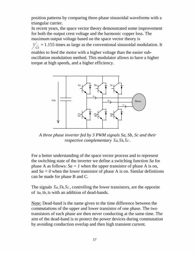
A three phase inverter fed by 3 PWM signals Sa, Sb, Sc and theirrespective complementary Sa Sb Sc, , .
For a better understanding of the space vector process and to representthe switching state of the inverter we define a switching function Sa forphase A as follows: Sa = 1 when the upper transistor of phase A is on,and Sa = 0 when the lower transistor of phase A is on. Similar definitionscan be made for phase B and C.
The signals Sa Sb Sc, , , controlling the lower transistors, are the oppositeof Sa Sb Sc, , with an addition of dead-bands.
Note: Dead-band is the name given to the time difference between thecommutations of the upper and lower transistor of one phase. The twotransistors of each phase are then never conducting at the same time. Theaim of the dead-band is to protect the power devices during commutationby avoiding conduction overlap and then high transient current.
18
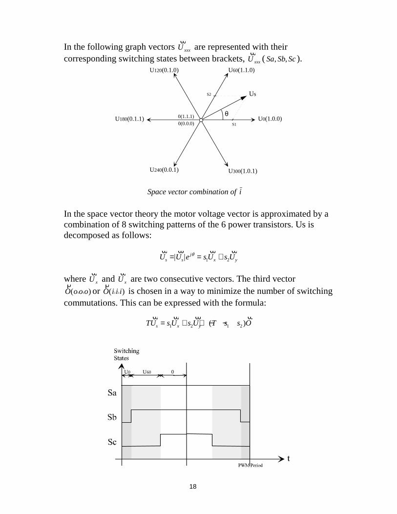
In the following graph vectors ϖ
U xxx are represented with theircorresponding switching states between brackets,
ϖU xxx ( Sa Sb Sc, , ).
U0(1.0.0)U180(0.1.1)
U240(0.0.1)
0(1.1.1) 0(0.0.0)
U120(0.1.0) U60(1.1.0)
U300(1.0.1)
θ
Us
S1
S2
Space vector combination of i
In the space vector theory the motor voltage vector is approximated by acombination of 8 switching patterns of the 6 power transistors. Us isdecomposed as follows:
ϖ ϖ ϖ ϖU U e s U s Us s
jx y= = +| | θ
1 2
where ϖ
U x and ϖ
U x are two consecutive vectors. The third vectorρ
O o o o( )1 1 or ρ
O i i i( )1 1 is chosen in a way to minimize the number of switchingcommutations. This can be expressed with the formula:
TU s U s U T s s Os x y
ϖ ϖ ϖ ϖ= + + − −1 2 1 2( )
U60 0U0

19
PWM states with 0 60≤ ≤θ deg
In the above case which is a symmetrical PWM generation, the first halfperiod of a PWM is built with the two PWM configurations U0 and U60characterized by the switching states (0,0,1) and (1,1,0) and the vector O:(1,1,1). The second half of the period has the same sequence but invertedrelated to time. This PWM scheme describes a vector Us with an angle θas 0 60≤ ≤θ deg .
The events manager of the TMS320C240 has a built-in hardware togreatly simplify the generation of symmetric space vector PWMwaveforms. The user has only to feed the corresponding registers withthe above mentioned combination, the two adjacent basic vectors (in ourexample U0 and U60) and the rotation direction. The output controlsignal update is instantaneous.
5.4 Field weakening at high speeds with closed loop schemeIn order to achieve high speeds, the stator current frequency is increased.The back-EMF Us is directly proportional to the motor flux Ψ and theangular speed ω . In normal condition the motor flux is kept constant.
U js ≈ ω.Ψ
Then a maximum stator speed is attained when Us reaches the limitoutput voltage of the power converter. To reach a higher speed, the fluxis reduced as an invert of the angular speed in order to keep the back-EMF constant and equal to its maximum.
ω
ψ0
ψUs
Usmax
Voltage controlrange
Field controlrange
Field controlrange
Field and voltage characteristics for high-speed control

20
Practically if we consider the stator current in the d,q rotating referenceframe and its relationship with the α,β stationary reference frame, belowthe speed where the maximum output voltage is reached, the best choiceis δ=±π/2 and isd=0. The effect of the field weakening can be achieved byadvancing the current vector beyond δ=π/2 i.e. introducing a currentcomponent in the negative d-axis. As a consequence isq and then thetorque are reduced in order not to exceed the maximum output currentis_max:
i i i is sd sq s= + ≤2 2_ max
Two schemes are possible to implement a field weakening operation. Thesimplest is the standard open loop control for the d-axis currentreference. Despite the relative simplicity of realization, it has thefollowing drawbacks:
• The reference current equation must be set in the worst condition ofoperation, it corresponds to the lower line voltage. It gives a lowutilization of the inverter with higher voltages.
• High-speed reliability: to guarantee the correct operation of the controlat high speeds it would have been necessary to reduce further thevoltage capability of the inverter.
• The reference current equation depends on the motor electricalcharacteristics, and it’s also necessary to consider the characteristicsdispersion in its determination.
A closed loop control avoids these negative effects. It consists in feedingback a proportional integral (PI) regulator with the motor d and q axisvoltages applied to the motor and calculate a new reference for themagnetizing current. This diagram allows to exploit the full voltagecapability of the inverter, independently from the line voltage and themotor characteristics.
5.5 Maximum DC bus voltage of the inverter controlIn case of a voltage supply variation the motor phase voltages have toremain constant. The DC bus voltage of the inverter is used to feedback acontrol loop containing a proportional regulator. The solution allows touse the motor as a brake, without the need of a ballast resistance forpower dissipation on the inverter. By means of the DC voltage control itis possible to use the motor to dissipate the braking energy. In this way,

21
the control regulates the maximum possible braking torque in order tokeep the maximum allowable DC bus voltage. This algorithm may needone A/D converter input to obtain the voltage. It is also possible tocalculate the voltage from the flux and the speed signals to avoid anadditional voltage sensor.
6. Sensor and sensorless algorithms
6.1 Current remote measurement and calculationIn most of the inverter systems, information on the phase currents isrequired. The first method of obtaining those currents is to directly sensethem but this requires, depending on the load schematic, at least twosensors applied directly on the motor phases. These types of sensors areusually expensive due to their sophisticated design and their need tooperate in isolation.
The other method is to sense only the line current, and estimate the 3phase currents. This second method requires a simple cheap SHUNT as asensor.
InputVoltage
Current estimator synoptic
As we directly control the inverters switching state, it is possible to knowthe exact electrical route taken by the input current through the inverterto the phase. We can then directly link the phase currents to the linecurrent. The information we measure to obtain the phase currents is aresult of a real sense on the current and not the result of a simulationrequiring a model of the output circuit. The measurement process istotally independent from the input and output hardware of the inverter.

22
The following figure gives an example of a switching state.
U V W
1
2
3
4
5
6
U dc
~UDCOUT
IDCOUT
Shunt
Inverter supplying a net of three star windings.
Based on the above example describing the switching state (Sa, Sb, Sc) =(0,0,1), one phase current ic can be related to the dc line current.Therefore three-phase currents can be measured, looking only at the dcline. If the Pulse Width Modulation period frequency is high enough, thephase current will only vary slightly over one or two PWM period.Hence, a measured phase current gives a reasonable approximation of theactual current.
To obtain the three-phase currents the DSP needs only one A/D channeland few calculations and a single resistor as current sensor whereas theclassical method requires 2 or 3 A/D channels and two isolated sensors.
-v
dr
qrdq
αβv
dr-i
di
θ
qi dqαβ
vαr
vβr
PMSM
PWM
SV
αβdc
D/Ainterface
iα
i β
qri-
= 0
dci
ωr
ωrref
Remote current sense control scheme of a PMSM Drive

23
6.2 Using a speed sensorThe two most common methods of sensing to sense motor speed on theshaft, are by using an encoder of a tachogenerator. For the encoder theTMS320C240 includes a module, the quadrature encoder pulse (Q.E.P.)which perfectly handles the situation and calculates the speed and thedirection of the rotation using only two digital inputs and a 16- or 32-bitinternal timer register.
There are several types of tachogenerators; some build a DC voltageproportional to the motor speed, and others generate a number of pulsesper rotor revolution.
In the first case, one of the sixteen A/D converter inputs is connected tothe tachogenerator output.
In the other case where hall effect sensor generates pulses, the signalenters a capture and a software driver allows the frequency measurement.The implemented software is called at fixed time intervals no longer thanthe minimum period of the measurable frequency. As there is only onesignal, it is not possible to measure the motor speed sign. An artifice isinserted to add the sign to this speed measurement. The speed sign ismemorized in a variable and only when the motor speed goes under apredetermined speed this variable is updated with the current sign. Thisalso allows the user to execute fast speed reversing cycles in the motor.
6.3 Sensorless controlled PMSM DriveIn some applications where constraints, efficiency, reliability, mechanicaland cost are all very important, it is not possible to use a speed, positionor a torque sensor. In such situations, the necessary information can bederived a dynamic model called a sliding mode observer. This strategyhas several advantages such as robustness and easy implementation.
Let us consider a sinusoidal permanent magnet synchronous motor thatuses the vector control method whereby the state variables aretransformed to a coordinate system rotating synchronous with the rotor.In rotor frame coordinates the PMSM behaves like a separately exitedDC motor. The exact value of the rotor position is mandatory to controlthe speed, to transform the state variables, and to achieve a highefficiency. The control scheme is illustrated below.
24
-v
dr
qrdq
αβv
dr-i
di
θ
qi dqαβ
vαr
vβr
PMSM
PWM
SV
αβabc
D/Ainterface
iα
i β
qri-
= 0
vαr
vβr
Rotor position
Observer
ia
bi
ωrref
ωr
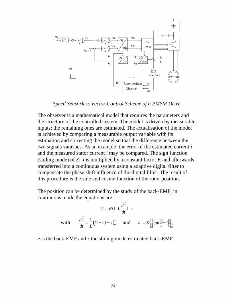
Speed Sensorless Vector Control Scheme of a PMSM Drive
The observer is a mathematical model that requires the parameters andthe structure of the controlled system. The model is driven by measurableinputs; the remaining ones are estimated. The actualisation of the modelis achieved by comparing a measurable output variable with itsestimation and correcting the model so that the difference between thetwo signals vanishes. As an example, the error of the estimated current îand the measured stator current i may be compared. The sign function(sliding mode) of ∆ i is multiplied by a constant factor K and afterwardstransferred into a continuous system using a adaptive digital filter tocompensate the phase shift influence of the digital filter. The result ofthis procedure is the sine and cosine function of the rotor position.
The position can be determined by the study of the back-EMF, incontinuous mode the equations are:
U Ri Ld i
dte= + +
^
with ( )d i
dt LU r i zs
^
= − −1 and z K sign i i= −
^
e is the back-EMF and z the sliding mode estimated back-EMF.

25
7. An example studiedBelow is an example of the implementation and realization of a PMSmotor controlled in speed and connected to an alternative voltagesupplier. Few results are given.
7.1 Power electronics
TMS320C240DSP
controller
InputFilter
Rectifier
AuxiliarySupply
InputVoltage
Inverter
synchronousmotor
communications
Load
Three-phase PMS motor driver
The input filter block includes the hardware protections, EMI filter andan optional power factor correction (PFC). The PFC may be active orpassive, in the case of active it can be entirely handled by the DSP. Toachieve a continuous voltage out of the alternative input signal, a single-phase input bridge with tank capacitor is needed represented as therectifier block. To generate the phase voltages with variable amplitudeand frequency a 3-phase inverter is used, based on an IGBT technology.The system is controlled by the DSP TMS320C240. The inputs are atachogenerator to measure the speed, a resistor divider to sense thevoltage bus (VBUS ), a resistor sensor on the line (IBUS ) to estimate thephase currents, and a temperature sensor. The controller uses a serial linkto communicate. The auxiliary supply feeds the inverter driver and thelogic circuitry.

26
7.2 The control strategy
Power Amp
Very high bandwidth current feedback
TMS320C240DSP
controller
System schematic
The above figure presents a complete system structure of a sensorlesscontrolled PMSM.
The control uses a space-vector PWM modulator. The speed, flux andcurrent controllers are all implemented using a standard PI regulatorblock, with double precision for integral part. The coordinatetransformation block is standard and uses the rotor angle to transform thestator phase currents values in the d-q axis frame. To reduce the numberof sensors, the phase currents are calculated from the DC bus currentwith the current estimator block and uses one shunt and no galvanic oroptical decoupling unit because the DSP controller is related already topower ground. No speed sensor is used, and the position sensor isreplaced by a sliding mode observer that requires a model of the motorbut does not need a close load behavior definition.
7.3 Software implementationThe proposed control scheme is implemented on the TMS320C240. Allthe control routines are implemented using assembler language withfixed precision numerical representation.
The control algorithm is synchronised by the DSP internal Timer thatgenerates interrupts.
Phase currents remote measurements need sampling of the inverter DCcurrent during the some PWM periods. The sampling time varies as afunction of the actual PWM pattern. This is obtained driving the A/Dconversion through another interrupt (compare register interrupt) and theresult is received through an end-of-conversion interrupt.

27
7.4 Few resultsThe calculation time of the whole control algorithm is less than 40 µs.The inverter switching frequency is 16 kHz. The speed control takes 2 µsand is calculated every 28 cycles, then 1.75 ms. Phase currents remotemeasurements need to sample the inverter DC current during the PWMperiod at instants that vary as a function of the actual PWM pattern. Thememory space needed is less than 1.2K word of ROM, 100 word of RAMand uses 70% (14 MIPS) of the DSP Controller performance.
The achieved electronic efficiency is higher than 95% and the totalefficiency > 90%.
The speed error was under worst-case conditions less than 1.5% and theresponse time to a speed step from 0 to base-speed is less than 5s.
8. Conclusion
This paper presents a new controller architecture the DSP-Controller andits single chip solutions for the control of a PMS motor. The DSP-Controller TMS320C240 combines the performance of a DSParchitecture with the optimized peripherals of a Microcontroller. Withthe DSP-Controller an intelligent control approach is possible to reducethe overall system costs and to improve the reliability of the drivesystem.
9. References
• ‘TMS320C240, TMS320F240 DSP controllers’ from TexasInstruments, October 1996
• ‘Control of Electrical Drives’ from Werner Leonhard, Ed.Springer,1996
• ‘Vector control of AC Drives’ Arpad Kelemen & Maria Imecs, Ed.G.J. Retter, 1987
• ‘Brushless Permanent-Magnet and Reluctance Motor Drives’ fromT.J.E. Miller, Oxford Science publications 1993
• ‘Brushless Permanent-Magnet Motor Design’ from Duane C.Hanselman, Ed Mc Graw Hill, 1994.