DS-KV61X3-(W)PE1 1 2 3 DS-KV6103-PE1 DS …...2019/09/30 · DS-KV6103-PE1 DS-KV6113-WPE1 IC...
4
DS-KV61X3-(W)PE1 Video Intercom Villa Door Staon Diagram References ENGLISH Appearance Indicator Descripon Installaon Accessory Acvate Device via Web Before you begin: Surface Mounng without Protecve Shield Surface Mounng without Protecve Shield 1 3 Installaon 4 Terminal and Wiring 2 Microphone Camera Indicator Unlock : Green Call: Orange Communicate: White 1 2 Mounng Template Mounng Plate 1 2 3 4 9 11 5 7 10 8 Make sure all related equipments are power-off during the installaon. Tools that you need to prepare for installaon: Drill (ø2.846) and gradienter. Purchase the protecve shield before installaon. 1. Sck the mounng template on the wall. Drill screw holes according to the mounng template. Remove the template from the wall. 2. Secure the mounng plate on the wall with 4 supplied screws according to the screw holes. 3. Install the villa door staon to the mounng plate. Fix the device on the mounng plate with the set screw. Surface Mounng with Protecve Shield Surface Mounng with Protecve Shield 1. Sck the mounng template on the wall. Drill screw holes according to the mounng template. Remove the template from the wall. 2. Align the protecve shield with the mounng template. 3. Secure the mounng plate and protecve shield on the wall with 4 supplied screws according to the screw holes. 4. Install the villa door staon to the mounng plate. Fix the device on the mounng plate with the set screw. 1. Power on the device, and connect the device to the network. 2. Enter the IP address into the address bar of the web browser, and click Enter to enter the acvaon page. Note:The computer and the device should belong to the same subnet. 3. Create and enter a password into the password field. 4. Confirm the password. 5. Click OK to acvate the device. Note: When the device is not acvated, the basic operaon and remote configuraon of device cannot be performed. You are required to acvate the device first by seng a strong password for it before you can use the device. Default parameters of door staon are as follows: Default IP Address: 192.0.0.65. Default Port No.: 8000. Default User Name: admin. Access to the Device by Web Browsers 1. In the browser address bar, enter the IP address of the device, and press the Enter key to enter the login page. 2. Enter the user name and password and click Login. Unlock Door Aſter issuing cards, you can unlock the door by presenng the issued card. Terminals TF Card Slot 12 Network Interface Buon Loudspeaker 6 Card Reading Area TAMPER NC: Door Lock Relay Output (NC) NO: Door Lock Relay Output (NO) COM: Common Interface GND: Grounding 12 VDC IN: Power Supply Input AIN1: For the access of Door Contact AIN3: For the access of Exit Buon AIN2 & AIN4: Reserved 485-: RS-485 Interface (Reserved) 485+: RS-485 Interface (Reserved) Set Screw Debugging Port Note: Debugging port is used for debugging only. Note: Video intercom villa door staon supports flush mounng and surface mounng. Note: The dimension of the mounng plate is 102.58 mm × 39.24 mm × 6.2 mm. Note: Configure the room No. of the indoor staon which is linked to the villa door staon. Refer to Video Intercom Indoor Staon User Manual for details. Configuraon via Web 5 Refer to Video Intercom Villa Door Staon User Manual (scan the QR code) for details. Only Mifare card supported, and Mifare card with non-standard shape is recommended. Up to 10000 cards can be issued and managed by V series door staon. A voice prompt (No more cards can be issued.) can be heard when the issued card amount exceeds the upper limit. UD16091B-B 4 1 2 3 1 1 1 2 Communicate with Indoor Staon 1. Click Sengs → Intercom → Press Buon to Call to enter the sengs page. 2. Set the parameters. -Edit call No. for every buon. -Check Call Management Center to set the buon calling center. Note: If you check Call Management Center and set the call No. as well, call management center has higher privilege than call No. 3. Press buon to call indoor staon. 3 5 3 4 2 5 Product Informaon Activation User Name Password Confirm OK 1. Click Sengs → Access Control and Elevator Control to enter the corresponding sengs page. 2. Click Issue Card. Present the card on the card reading area. 3. When issuing finished, the windows pop up on the sengs page. Issue Card 4 1 2 3 4 7 8 9 10 6 5 11 12 RS-485+ RS-485- Orange Yellow Red 12 VDC GND AIN1 AIN2 AIN3 AIN4 NC NO Black White White White Yellow Blue COM Green GND GND Black Black White PRESS Exit Button TO EXIT Reserved Power Input The recommended distance from the ground level is 1.40 adjustable depends on the height of body. 102023104 Hole1 Hole2 Hole1 Hole1 Hole1 102.58 1.18 Unit : mm 6.2 39.24 3.45 2 1 3 Screws Screw Villa Door Station Mounting Plate Mounting Template Wall 1 3 4 2 Screws Screws Screw Villa Door Station Mounting Plate Protective Shield Mounting Template Wall ©2019 Hangzhou Hikvision Digital Technology Co., Ltd. It includes instrucons on how to use the Product. The soſtware embodied in the Product is governed by the user license agreement covering that Product. About this Manual This Manual is subject to domesc and internaonal copyright protecon. Hangzhou Hikvision Digital Technology Co., Ltd. (“Hikvision”) reserves all rights to this manual. This manual cannot be reproduced, changed, translated, or distributed, parally or wholly, by any means, without the prior wrien permission of Hikvision. Trademarks and other Hikvision marks are the property of Hikvision and are registered trademarks or the subject of applicaons for the same by Hikvision and/or its affiliates. Other trademarks menoned in this manual are the properes of their respecve owners. No right of license is given to use such trademarks without express permission. Legal Disclaimer TO THE MAXIMUM EXTENT PERMITTED BY APPLICABLE LAW, THE PRODUCT DESCRIBED, WITH ITS HARDWARE, SOFTWARE AND FIRMWARE, IS PROVIDED “AS IS”, WITH ALL FAULTS AND ERRORS, AND HIKVISION MAKES NO WARRANTIES, EXPRESS OR IMPLIED, INCLUDING WITHOUT LIMITATION, MERCHANTABILITY, SATISFACTORY QUALITY, FITNESS FOR A PARTICULAR PURPOSE, AND NON-INFRINGEMENT OF THIRD PARTY. IN NO EVENT WILL HIKVISION, ITS DIRECTORS, OFFICERS, EMPLOYEES, OR AGENTS BE LIABLE TO YOU FOR ANY SPECIAL, CONSEQUENTIAL, INCIDENTAL, OR INDIRECT DAMAGES, INCLUDING, AMONG OTHERS, DAMAGES FOR LOSS OF BUSINESS PROFITS, BUSINESS INTERRUPTION, OR LOSS OF DATA OR DOCUMENTATION, IN CONNECTION WITH THE USE OF THIS PRODUCT, EVEN IF HIKVISION HAS BEEN ADVISED OF THE POSSIBILITY OF SUCH DAMAGES. REGARDING TO THE PRODUCT WITH INTERNET ACCESS, THE USE OF PRODUCT SHALL BE WHOLLY AT YOUR OWN RISKS. HIKVISION SHALL NOT TAKE ANY RESPONSIBILITIES FOR ABNORMAL OPERATION, PRIVACY LEAKAGE OR OTHER DAMAGES RESULTING FROM CYBER ATTACK, HACKER ATTACK, VIRUS INSPECTION, OR OTHER INTERNET SECURITY RISKS; HOWEVER, HIKVISION WILL PROVIDE TIMELY TECHNICAL SUPPORT IF REQUIRED. SURVEILLANCE LAWS VARY BY JURISDICTION. PLEASE CHECK ALL RELEVANT LAWS IN YOUR JURISDICTION BEFORE USING THIS PRODUCT IN ORDER TO ENSURE THAT YOUR USE CONFORMS THE APPLICABLE LAW. HIKVISION SHALL NOT BE LIABLE IN THE EVENT THAT THIS PRODUCT IS USED WITH ILLEGITIMATE PURPOSES. IN THE EVENT OF ANY CONFLICTS BETWEEN THIS MANUAL AND THE APPLICABLE LAW, THE LATER PREVAILS. Data Protecon During the use of device, personal data will be collected, stored and processed. To protect data, the development of Hikvision devices incorporates privacy by design principles. For example, for device with facial recognion features, biometrics data is stored in your device with encrypon method; for fingerprint device, only fingerprint template will be saved, which is impossible to reconstruct a fingerprint image. As data controller, you are advised to collect, store, process and transfer data in accordance with the applicable data protecon laws and regulaons, including without limitaon, conducng security controls to safeguard personal data, such as, implemenng reasonable administrave and physical security controls, conduct periodic reviews and assessments of the effecveness of your security controls. Scan the QR code to get the user manual for detailed inforamon. This product and - if applicable - the supplied accessories too are marked with "CE" and comply therefore with the applicable harmonized European standards listed under the RE Direcve 2014/53/EU, the EMC Direcve 2014/30/EU, the RoHS Direcve 2011/65/EU. 2012/19/EU (WEEE direcve): Products marked with this symbol cannot be disposed of as unsorted municipal waste in the European Union. For proper recycling, return this product to your local supplier upon the purchase of equivalent new equipment, or dispose of it at designated collecon points. For more informaon see: www.recyclethis.info 2006/66/EC (baery direcve): This product contains a baery that cannot be disposed of as unsorted municipal waste in the European Union. See the product documentaon for specific baery informaon. The baery is marked with this symbol, which may include leering to indicate cadmium (Cd), lead (Pb), or mercury (Hg). For proper recycling, return the baery to your supplier or to a designated collecon point. For more informaon see: www.recyclethis.info FCC Conditions This device complies with part 15 of the FCC Rules. Operaon is subject to the following two condions: 1. This device may not cause harmful interference. 2. This device must accept any interference received, including interference that may cause undesired operaon. EU Conformity Statement FCC Information Please take aenon that changes or modificaon not expressly approved by the party responsible for compliance could void the user’s authority to operate the equipment. FCC compliance: This equipment has been tested and found to comply with the limits for a Class B digital device, pursuant to part 15 of the FCC Rules. These limits are designed to provide reasonable protecon against harmful interference in a residenal installaon. This equipment generates, uses and can radiate radio frequency energy and, if not installed and used in accordance with the instrucons, may cause harmful interference to radio communicaons. However, there is no guarantee that interference will not occur in a parcular installaon. If this equipment does cause harmful interference to radio or television recepon, which can be determined by turning the equipment off and on, the user is encouraged to try to correct the interference by one or more of the following measures: —Reorient or relocate the receiving antenna. —Increase the separaon between the equipment and receiver. —Connect the equipment into an outlet on a circuit different from that to which the receiver is connected. —Consult the dealer or an experienced radio/TV technician for help. This equipment should be installed and operated with a minimum distance 20cm between the radiator and your body. Vaild password range [8-16]. You can use a combinaon of numbers, lowercase, uppercase and special character for your password with at least two kinds of them contained. Buon Sengs Buon 1 0 Call Call Management Center DS-KV6103-PE1 DS-KV6113-WPE1 IC statement This device complies with Industry Canada licence-exempt RSS standard(s). Operaon is subject to the following two condions: (1) this device may not cause interference, and (2) this device must accept any interference, including interference that may cause undesired operaon of the device. Le présent appareil est conforme aux CNR d'Industrie Canada applicables aux appareils radioexempts de licence. L'exploitaon est autorisée aux deux condions suivantes : (1) l'appareil ne doit pas produire de brouillage, et (2) l'ulisateur de l'appareil doit accepter tout brouillage radioélectrique subi, même si le brouillage est suscepble d'en compromere le fonconnement. Under Industry Canada regulaons, this radio transmier may only operate using an antenna of a type and maximum (or lesser) gain approved for the transmier by Industry Canada. To reduce potenal radio interference to other users, the antenna type and its gain should be so chosen that the equivalent isotropically radiated power (e.i.r.p.) is not more than that necessary for successful communicaon. Conformément à la réglementaon d'Industrie Canada, le présent émeeur radio peut fonconner avec une antenne d'un type et d'un gain maximal (ou inférieur) approuvé pour l'émeeur par Industrie Canada. Dans le but de réduire les risques de brouillage radioélectrique à l'intenon des autres ulisateurs, il faut choisir le type d'antenne et son gain de sorte que la puissance isotrope rayonnée équivalente (p.i.r.e.) ne dépasse pas l'intensité nécessaire à l'établissement d'une communicaon sasfaisante. This equipment complies with IC RSS-102 radiaon exposure limits set forth for an uncontrolled environment. This equipment should be installed and operated with minimum distance 20cm between the radiator & your body. ce matériel est conforme aux limites de dose d'exposion aux rayonnements, CNR-102 énoncée dans un autre environnement.cee eqipment devrait être installé et exploité avec distance minimale de 20 entre le radiateur et votre corps.
Transcript of DS-KV61X3-(W)PE1 1 2 3 DS-KV6103-PE1 DS …...2019/09/30 · DS-KV6103-PE1 DS-KV6113-WPE1 IC...
DS-KV61X3-(W)PE1Video Intercom Villa Door Station
Diagram References
E N G L I S H
Appearance
Indicator Description
Installation Accessory
Activate Device via Web
Before you begin:
Surface Mounting without Protective Shield
Surface Mounting without Protective Shield
1
3
Installation4
Terminal and Wiring2
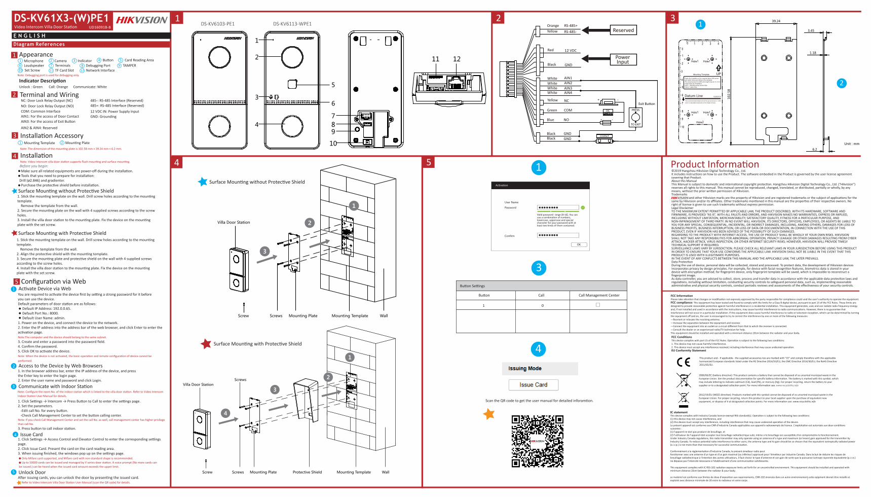
Microphone Camera Indicator
Unlock : Green Call: Orange Communicate: White
1 2
Mounting Template Mounting Plate1 2
3 49
11
57
108
Make sure all related equipments are power-off during the installation. Tools that you need to prepare for installation:Drill (ø2.846) and gradienter. Purchase the protective shield before installation.
1. Stick the mounting template on the wall. Drill screw holes according to the mounting template. Remove the template from the wall.2. Secure the mounting plate on the wall with 4 supplied screws according to the screw holes.3. Install the villa door station to the mounting plate. Fix the device on the mounting plate with the set screw.
Surface Mounting with Protective Shield
Surface Mounting with Protective Shield
1. Stick the mounting template on the wall. Drill screw holes according to the mounting template. Remove the template from the wall.2. Align the protective shield with the mounting template.3. Secure the mounting plate and protective shield on the wall with 4 supplied screws according to the screw holes.4. Install the villa door station to the mounting plate. Fix the device on the mounting plate with the set screw.
1. Power on the device, and connect the device to the network.2. Enter the IP address into the address bar of the web browser, and click Enter to enter the activation page.Note:The computer and the device should belong to the same subnet. 3. Create and enter a password into the password field.4. Confirm the password.5. Click OK to activate the device.Note: When the device is not activated, the basic operation and remote configuration of device cannot be performed.
You are required to activate the device first by setting a strong password for it beforeyou can use the device.Default parameters of door station are as follows: Default IP Address: 192.0.0.65. Default Port No.: 8000. Default User Name: admin.
Access to the Device by Web Browsers1. In the browser address bar, enter the IP address of the device, and pressthe Enter key to enter the login page.2. Enter the user name and password and click Login.
Unlock DoorAfter issuing cards, you can unlock the door by presenting the issued card.
TerminalsTF Card Slot 12 Network Interface
ButtonLoudspeaker6
Card Reading AreaTAMPER
NC: Door Lock Relay Output (NC)NO: Door Lock Relay Output (NO)COM: Common Interface
GND: Grounding12 VDC IN: Power Supply Input
AIN1: For the access of Door ContactAIN3: For the access of Exit Button
AIN2 & AIN4: Reserved
485-: RS-485 Interface (Reserved)485+: RS-485 Interface (Reserved)
Set ScrewDebugging Port
Note: Debugging port is used for debugging only.
Note: Video intercom villa door station supports flush mounting and surface mounting.
Note: The dimension of the mounting plate is 102.58 mm × 39.24 mm × 6.2 mm.
Note: Configure the room No. of the indoor station which is linked to the villa door station. Refer to Video Intercom Indoor Station User Manual for details.
Configuration via Web5
Refer to Video Intercom Villa Door Station User Manual (scan the QR code) for details.
Only Mifare card supported, and Mifare card with non-standard shape is recommended. Up to 10000 cards can be issued and managed by V series door station. A voice prompt (No more cards can be issued.) can be heard when the issued card amount exceeds the upper limit.
UD16091B-B
4
1 2 3
1
1
1
2
Communicate with Indoor Station
1. Click Settings → Intercom → Press Button to Call to enter the settings page.2. Set the parameters. -Edit call No. for every button. -Check Call Management Center to set the button calling center.Note: If you check Call Management Center and set the call No. as well, call management center has higher privilege than call No.3. Press button to call indoor station.
3
5
3
4
2
5 Product Information
Activation
User Name
Password
Confirm
OK
1. Click Settings → Access Control and Elevator Control to enter the corresponding settings page.2. Click Issue Card. Present the card on the card reading area. 3. When issuing finished, the windows pop up on the settings page.
Issue Card4
1
2
3
4789
10
6
5
11 12
RS-485+RS-485-
OrangeYellow
Red 12 VDC
GND
AIN1AIN2AIN3AIN4
NC
NO
Black
White
WhiteWhite
Yellow
Blue
COMGreen
GNDGND
BlackBlack
White
PRESS
Exit Button
TO EXIT
Reserved
Power Input
The recommended distance from the ground level is 1.40adjustable depends on the height of body.
102023104
Hole1
Hole2
Hole1
Hole1 Hole1
102.
58
1.18
Unit : mm
6.2
39.24
3.45
2
1
3
ScrewsScrew
Villa Door Station
Mounting Plate Mounting Template Wall
1
3
4
2
Screws
Screws
Screw
Villa Door Station
Mounting Plate Protective Shield Mounting Template Wall
©2019 Hangzhou Hikvision Digital Technology Co., Ltd. It includes instructions on how to use the Product. The software embodied in the Product is governed by the user license agreement covering that Product.About this ManualThis Manual is subject to domestic and international copyright protection. Hangzhou Hikvision Digital Technology Co., Ltd. (“Hikvision”) reserves all rights to this manual. This manual cannot be reproduced, changed, translated, or distributed, partially or wholly, by any means, without the prior written permission of Hikvision. Trademarks and other Hikvision marks are the property of Hikvision and are registered trademarks or the subject of applications for the same by Hikvision and/or its affiliates. Other trademarks mentioned in this manual are the properties of their respective owners. No right of license is given to use such trademarks without express permission.Legal DisclaimerTO THE MAXIMUM EXTENT PERMITTED BY APPLICABLE LAW, THE PRODUCT DESCRIBED, WITH ITS HARDWARE, SOFTWARE AND FIRMWARE, IS PROVIDED “AS IS”, WITH ALL FAULTS AND ERRORS, AND HIKVISION MAKES NO WARRANTIES, EXPRESS OR IMPLIED, INCLUDING WITHOUT LIMITATION, MERCHANTABILITY, SATISFACTORY QUALITY, FITNESS FOR A PARTICULAR PURPOSE, AND NON-INFRINGEMENT OF THIRD PARTY. IN NO EVENT WILL HIKVISION, ITS DIRECTORS, OFFICERS, EMPLOYEES, OR AGENTS BE LIABLE TO YOU FOR ANY SPECIAL, CONSEQUENTIAL, INCIDENTAL, OR INDIRECT DAMAGES, INCLUDING, AMONG OTHERS, DAMAGES FOR LOSS OF BUSINESS PROFITS, BUSINESS INTERRUPTION, OR LOSS OF DATA OR DOCUMENTATION, IN CONNECTION WITH THE USE OF THIS PRODUCT, EVEN IF HIKVISION HAS BEEN ADVISED OF THE POSSIBILITY OF SUCH DAMAGES.REGARDING TO THE PRODUCT WITH INTERNET ACCESS, THE USE OF PRODUCT SHALL BE WHOLLY AT YOUR OWN RISKS. HIKVISION SHALL NOT TAKE ANY RESPONSIBILITIES FOR ABNORMAL OPERATION, PRIVACY LEAKAGE OR OTHER DAMAGES RESULTING FROM CYBER ATTACK, HACKER ATTACK, VIRUS INSPECTION, OR OTHER INTERNET SECURITY RISKS; HOWEVER, HIKVISION WILL PROVIDE TIMELY TECHNICAL SUPPORT IF REQUIRED. SURVEILLANCE LAWS VARY BY JURISDICTION. PLEASE CHECK ALL RELEVANT LAWS IN YOUR JURISDICTION BEFORE USING THIS PRODUCT IN ORDER TO ENSURE THAT YOUR USE CONFORMS THE APPLICABLE LAW. HIKVISION SHALL NOT BE LIABLE IN THE EVENT THAT THIS PRODUCT IS USED WITH ILLEGITIMATE PURPOSES. IN THE EVENT OF ANY CONFLICTS BETWEEN THIS MANUAL AND THE APPLICABLE LAW, THE LATER PREVAILS.Data ProtectionDuring the use of device, personal data will be collected, stored and processed. To protect data, the development of Hikvision devices incorporates privacy by design principles. For example, for device with facial recognition features, biometrics data is stored in your device with encryption method; for fingerprint device, only fingerprint template will be saved, which is impossible to reconstruct a fingerprint image. As data controller, you are advised to collect, store, process and transfer data in accordance with the applicable data protection laws and regulations, including without limitation, conducting security controls to safeguard personal data, such as, implementing reasonable administrative and physical security controls, conduct periodic reviews and assessments of the effectiveness of your security controls.
Scan the QR code to get the user manual for detailed inforamtion.
This product and - if applicable - the supplied accessories too are marked with "CE" and comply therefore with the applicable harmonized European standards listed under the RE Directive 2014/53/EU, the EMC Directive 2014/30/EU, the RoHS Directive 2011/65/EU.
2012/19/EU (WEEE directive): Products marked with this symbol cannot be disposed of as unsorted municipal waste in the European Union. For proper recycling, return this product to your local supplier upon the purchase of equivalent new equipment, or dispose of it at designated collection points. For more information see: www.recyclethis.info
2006/66/EC (battery directive): This product contains a battery that cannot be disposed of as unsorted municipal waste in the European Union. See the product documentation for specific battery information. The battery is marked with this symbol, which may include lettering to indicate cadmium (Cd), lead (Pb), or mercury (Hg). For proper recycling, return the battery to your supplier or to a designated collection point. For more information see: www.recyclethis.info
FCC ConditionsThis device complies with part 15 of the FCC Rules. Operation is subject to the following two conditions:1. This device may not cause harmful interference.2. This device must accept any interference received, including interference that may cause undesired operation.EU Conformity Statement
FCC InformationPlease take attention that changes or modification not expressly approved by the party responsible for compliance could void the user’s authority to operate the equipment.FCC compliance: This equipment has been tested and found to comply with the limits for a Class B digital device, pursuant to part 15 of the FCC Rules. These limits are designed to provide reasonable protection against harmful interference in a residential installation. This equipment generates, uses and can radiate radio frequency energy and, if not installed and used in accordance with the instructions, may cause harmful interference to radio communications. However, there is no guarantee that interference will not occur in a particular installation. If this equipment does cause harmful interference to radio or television reception, which can be determined by turning the equipment off and on, the user is encouraged to try to correct the interference by one or more of the following measures:—Reorient or relocate the receiving antenna.—Increase the separation between the equipment and receiver.—Connect the equipment into an outlet on a circuit different from that to which the receiver is connected.—Consult the dealer or an experienced radio/TV technician for help.This equipment should be installed and operated with a minimum distance 20cm between the radiator and your body.
Vaild password range [8-16]. You can use a combination of numbers, lowercase, uppercase and special character for your password with at least two kinds of them contained.
Button Settings
Button
1 0
Call Call Management Center
DS-KV6103-PE1 DS-KV6113-WPE1
IC statementThis device complies with Industry Canada licence-exempt RSS standard(s). Operation is subject to the following two conditions: (1) this device may not cause interference, and(2) this device must accept any interference, including interference that may cause undesired operation of the device.Le présent appareil est conforme aux CNR d'Industrie Canada applicables aux appareils radioexempts de licence. L'exploitation est autorisée aux deux conditions suivantes :(1) l'appareil ne doit pas produire de brouillage, et(2) l'utilisateur de l'appareil doit accepter tout brouillage radioélectrique subi, même si le brouillage est susceptible d'en compromettre le fonctionnement.Under Industry Canada regulations, this radio transmitter may only operate using an antenna of a type and maximum (or lesser) gain approved for the transmitter by Industry Canada. To reduce potential radio interference to other users, the antenna type and its gain should be so chosen that the equivalent isotropically radiated power (e.i.r.p.) is not more than that necessary for successful communication.
Conformément à la réglementation d'Industrie Canada, le présent émetteur radio peutfonctionner avec une antenne d'un type et d'un gain maximal (ou inférieur) approuvé pour l'émetteur par Industrie Canada. Dans le but de réduire les risques de brouillage radioélectrique à l'intention des autres utilisateurs, il faut choisir le type d'antenne et son gain de sorte que la puissance isotrope rayonnée équivalente (p.i.r.e.) ne dépasse pas l'intensité nécessaire à l'établissement d'une communication satisfaisante.
This equipment complies with IC RSS-102 radiation exposure limits set forth for an uncontrolled environment. This equipment should be installed and operated with minimum distance 20cm between the radiator & your body.
ce matériel est conforme aux limites de dose d'exposition aux rayonnements, CNR-102 énoncée dans un autre environnement.cette eqipment devrait être installé et exploité avec distance minimale de 20 entre le radiateur et votre corps.

Referencias del diagramaE S P A Ñ O L
Apariencia
Nota: el puerto de depuración solo se utiliza para eliminar fallos del sistema.
Descripción del indicadorDesbloquear: verde Llamar: naranja Comunicar: blanco
Accesorio de instalación
1
3
4
Terminal y cableado2
Micrófono Cámara Indicador1 2
Plantilla de montaje Placa de montaje1 2
3 4
9
11
5
7
10
8Terminales
Ranura para tarjeta TF 12 interfaz de red
Botón
Altavoz6
Área de lectura de tarjetas
MANIPULACIÓN
NC: salida de relé de cerradura de puerta (NC)NA: salida de relé de cerradura de puerta (NA)COM: interfaz comúnAIN1: para el acceso del contacto de la puertaAIN3: para el acceso del botón de salidaAIN2 y AIN4: reservado
485-: interfaz RS-485 (reservada)485+: interfaz RS-485 (reservada)ENTRADA 12 VCC: entrada de la fuente de alimentaciónTIERRA: conexión a tierra
Tornillo de presión
Puerto de depuración
Nota: Las dimensiones de la placa de montaje son de 102,58 mm × 39,24 mm × 6,2 mm.
InstalaciónNota: la estación de vídeo intercomunicador para puerta de chalé es compatible con el montaje empotrado y el montaje en superficie.Antes de empezar:• Asegúrese de que todos los equipos relacionados estén apagados durante la instalación.• Herramientas que necesita para la instalación: Taladro (ø2,846) y nivel.• Adquiera la chapa protectora antes de la instalación.
Montaje en superficie sin chapa protectora1. Pegue la plantilla de montaje en la pared. Taladre los agujeros para los tornillos según la plantilla
de montaje. Retire la plantilla de la pared.2. Sujete la placa de montaje en la pared colocando los 4 tornillos incluidos en sus agujeros
correspondientes.3. Instale la estación para puerta de chalé en la placa de montaje. Fije el dispositivo en la placa de
montaje con el tornillo de presión.
Montaje en superficie con chapa protectora1. Pegue la plantilla de montaje en la pared. Taladre los agujeros para los tornillos según la plantilla
de montaje. Retire la plantilla de la pared.2. Alinee la chapa protectora con la plantilla de montaje.3. Sujete la placa de montaje y la chapa protectora en la pared colocando los 4 tornillos incluidos en
sus agujeros correspondientes.4. Instale la estación para puerta de chalé en la placa de montaje. Fije el dispositivo en la placa de
montaje con el tornillo de presión.
Configuración a través de la webActivar el dispositivo a través de la webAntes de poder utilizar el dispositivo es necesario activarlo estableciendo una contraseña segura.Los parámetros predeterminados de la estación para puerta son los siguientes:• Dirección IP predeterminada: 192.0.0.65.• N.º de puerto predeterminado: 8000.• Nombre de usuario predeterminado: admin.1. Encienda el dispositivo y conéctelo a la red.2. Introduzca la dirección IP en la barra de direcciones del navegador web y pulse Intro para acceder
a la página de activación.Nota: el ordenador y el dispositivo deben pertenecer a la misma subred. 3. Cree una contraseña e introdúzcala en el campo de contraseña.4. Confirme la contraseña.5. Haga clic en OK para activar el dispositivo.Nota: si el dispositivo no está activado, las operaciones básicas y la configuración remota no se podrán realizar.
Acceso al dispositivo a través de navegadores web1. En la barra de direcciones del navegador, introduzca la dirección IP del dispositivo y pulse la tecla
Intro para acceder a la página de inicio de sesión.2. Introduzca el nombre de usuario y la contraseña y haga clic en Iniciar sesión.
Comunicarse con la estación interiorNota: configure el n.º de habitación de la estación interior que esté vinculado con la estación para puerta de chalé. Consulte el manual de usuario de la estación interior de vídeo intercomunicador para más información.1. Haga clic en Ajustes → Intercomunicador → Pulsar botón para llamar, para acceder a la página de
ajustes2. Configure los parámetros.
- Edite el n.º de llamada de todos los botones.- Marque Centro de administración de llamadas para establecer el botón del centro de llamadas.
Nota: si marca Centro de administración de llamadas y establece también el n.º de llamada, el centro de administración de llamadas tendrá más privilegios que el n.º de llamada.3. Pulse el botón para llamar a la estación interior.
Emitir tarjeta1. Haga clic en Ajustes → Control de acceso y control de ascensor, para acceder a la página de
ajustes correspondiente.2. Haga clic en Emitir tarjeta. Coloque la tarjeta en el área de lectura de tarjetas. 3. Cuando la emisión finalice, las ventanas aparecerán en la página de ajustes.• Solo es compatible con tarjetas Mifare y se recomiendan tarjetas Mifare de forma no estándar.• Las estaciones para puertas de la gama V pueden emitir y administrar hasta 10000 tarjetas. Se oirá un aviso
de voz ("no se pueden emitir más tarjetas") cuando la cantidad de tarjetas emitidas supere el límite.
Desbloquear puertaDespués de emitir las tarjetas, puede desbloquear la puerta presentando la tarjeta emitida.
Consulte el manual de usuario de la estación de vídeo intercomunicador para puerta de chalé (escanee el código QR) para más información.
51
2
3
5
4
Verweise auf Schaubilder
D E U T S C H
Optik
Hinweis: Debugging-Anschluss dient ausschließlich dem Debugging.
AnzeigenEntriegeln: Grün Anruf: Orange Kommunikation: Weiß
Installationszubehör
1
3
4
Anschlüsse und Verkabelung2
Mikrofon Kamera Statusanzeige1 2
Montageschablone Montageplatte1 2
3 4
9
11
5
7
10
8AnschlussklemmenmicroSD-Kartensteckplatz 12 Netzwerkanschluss
Taste
Lautsprecher6
Kartenlesebereich
SABOTAGE
NC: Türschloss-Relaisausgang (NC)NO: Türschloss-Relaisausgang (NO)COM: Allgemeine SchnittstelleAIN1: Für den Anschluss des TürkontaktsAIN3: Für den Anschluss der AusgangstasteAIN2 und AIN4: Reserviert
485-: RS-485-Schnittstelle (reserviert)485+: RS-485-Schnittstelle (reserviert)12-V-Gleichspannungseingang: StromversorgungseingangMasse: Masse
Feststellschraube
Debug-Anschluss
Hinweis: Die Abmessungen der Montageplatte betragen 102,58 × 39,24 × 6,2 mm.
InstallationHinweis: Einfamilienhaus-Türstation mit Video-Gegensprechfunktion unterstützt Unterputz- und Aufputzmontage.Bevor Sie beginnen:• Achten Sie darauf, dass alle relevanten Geräte während der Montage ausgeschaltet sind.• Werkzeuge, die Sie für die Montage vorbereiten müssen: Bohrer (Ø 2,846) und Wasserwaage.• Kaufen Sie die Schutzabdeckung vor der Installation.
Aufputzmontage ohne Schutzabdeckung1. Kleben Sie die Montageschablone an die Wand. Bohren Sie Schraubenlöcher entsprechend der
Montageschablone. Entfernen Sie die Schablone von der Wand.2. Befestigen Sie die Montageplatte entsprechend den Schraubenlöchern mit 4 mitgelieferten
Schrauben an der Wand.3. Installieren Sie die Einfamilienhaus-Türstation auf der Montageplatte. Befestigen Sie das Gerät mit
der Feststellschraube auf der Montageplatte.
Aufputzmontage mit Schutzabdeckung1. Kleben Sie die Montageschablone an die Wand. Bohren Sie Schraubenlöcher entsprechend der
Montageschablone. Entfernen Sie die Schablone von der Wand.2. Richten Sie die Schutzabdeckung mit der Montageschablone aus.3. Befestigen Sie Montageplatte und Schutzabdeckung entsprechend den Schraubenlöchern mit 4
mitgelieferten Schrauben an der Wand.4. Installieren Sie die Einfamilienhaus-Türstation auf der Montageplatte. Befestigen Sie das Gerät mit
der Feststellschraube auf der Montageplatte.
Konfiguration über das InternetGeräteaktivierung über das InternetSie müssen das Gerät vor der Verwendung zunächst aktivieren, indem Sie ein starkes Passwort festlegen.Standardparameter der Türstation sind wie folgt:• Standard-IP-Adresse: 192.0.0.65.• Standard-Port-Nr.: 8000.• Standard-Benutzername: admin.1. Schalten Sie das Gerät ein und verbinden Sie es mit dem Netzwerk.2. Geben Sie die IP-Adresse in die Adresszeile des Webbrowsers ein und drücken Sie Enter, um die
Aktivierungsseite aufzurufen.Hinweis: Computer und Gerät müssen sich im selben Subnetz befinden. 3. Erstellen Sie ein Passwort und geben Sie dieses in das Passwortfeld ein.4. Bestätigen Sie das Kennwort.5. Klicken Sie zum Aktivieren des Geräts auf OK.Hinweis: Wenn das Gerät nicht aktiviert ist, können grundlegende Bedienung und Fernkonfiguration des Gerätes nicht durchgeführt werden.
Zugriff auf das Gerät über Webbrowser1. Geben Sie in die Adresszeile des Browsers die IP-Adresse des Gerätes ein und drücken Sie zum
Aufrufen der Anmeldeseite Enter.2. Geben Sie den Benutzernamen und das Passwort ein und klicken Sie auf Anmelden.
Mit der Innenstation kommunizierenHinweis: Konfigurieren Sie die Raum-Nr. der Innenstation, die mit der Türstation des Einfamilienhauses verbunden ist. Einzelheiten können Sie dem Benutzerhandbuch der Innenstation mit Video-Gegensprechfunktion entnehmen.1. Klicken Sie zum Aufrufen der Einstellungsseite auf Einstellungen → Gegensprechen → Zum
Anrufen Taste drücken.2. Legen Sie die Parameter fest.
- Bearbeiten Sie die Anruf-Nr. für jede Taste.- Aktivieren Sie das Kontrollkästchen Anrufmanagement-Center, um die Taste Center anrufen
einzustellen.Hinweis: Wenn Sie das Kontrollkästchen Anrufmanagement-Center aktivieren und die Anruf-Nr. festlegen, hat das Anrufmanagement-Center Vorrang vor der Anruf-Nr.3. Drücken Sie die Taste zum Anrufen der Innenstation.
Ausstellen einer Karte1. Klicken Sie zum Aufrufen der entsprechenden Einstellungsseite auf Einstellungen →
Zutrittskontrolle und Fahrstuhlüberwachung.2. Klicken Sie auf Karte ausstellen. Zeigen Sie die Karte am Kartenlesebereich vor. 3. Bei Abschluss der Ausstellung erscheint ein Fenster auf der Einstellungsseite.• Es werden nur Mifare-Karten unterstützt; zudem werden Mifare-Karten mit nicht standardmäßiger Form
empfohlen.• Über die Türstation der V-Serie können bis zu 10000 Karten ausgestellt und verwaltet werden. Sobald die
Kartenanzahl die Obergrenze erreicht, erfolgt die Ansage (Es können keine weiteren Karten ausgestellt werden).
Tür entriegelnNach der Kartenausstellung können Sie die Tür durch Vorzeigen der ausgestellten Karte entriegeln.
Weitere Informationen finden Sie im Benutzerhandbuch der Einfamilienhaus-Türstation mit Video-Gegensprechfunktion (scannen Sie den QR-Code).
51
2
3
5
4
Références du schéma
F R A N Ç A I S
Apparence
Remarque : le port de débogage sert uniquement au débogage.
Description de l’indicateurDéverrouillage : vert Appeler : orange Communiquer : blanc
Accessoire d’installation
1
3
4
Borne et câblage2
Microphone Caméra Indicateur1 2
Gabarit de montage Plaque de fixation1 2
3 4
9
11
5
7
10
8Bornes
Fente pour carte TF 12 interface réseau
Touche
Haut-parleur6
Zone de lecture de carteSABOTAGE
NF : sortie du relais de verrou de porte (NF)NO : sortie du relais de verrou de porte (NO)COM : interface communeAIN1 : pour l’accès au contact de porteAIN3 : pour l’accès au bouton de sortieAIN2 & AIN4 : réservé
485- : interface RS-485 (réservé)485+ : interface RS-485 (réservé)Entrée 12 V CC : entrée d’alimentation électriqueGND : mise à la terre
Vis de blocage
Port de dépannage
Remarque : les dimensions de la plaque de montage sont 102,58 mm × 39,24 mm × 6,2 mm.
InstallationRemarque : la station de porte de villa à interphone vidéo prend en charge le montage encastré et le montage en surface.Avant de commencer :• Assurez-vous que tous les équipements associés sont hors tension lors de l’installation.• Préparez les outils nécessaires à l’installation : Perceuse (ø2,846) et gradienteur.• Achetez l’écran de protection avant l’installation.
Montage en surface sans écran de protection1. Collez le gabarit de perçage au mur. Percez des trous de vis conformément au gabarit de perçage.
Retirez le gabarit du mur.2. Fixez la plaque de montage au mur avec les 4 vis fournies à travers les trous prévus à cet effet.3. Installez la station de porte de villa à la plaque de montage. Fixez l’appareil sur la plaque de
montage avec la vis de blocage.
Montage en surface avec écran de protection1. Collez le gabarit de perçage au mur. Percez des trous de vis conformément au gabarit de perçage.
Retirez le gabarit du mur.2. Alignez l’écran de protection avec le gabarit de perçage.3. Fixez la plaque de montage et l’écran de protection au mur avec les 4 vis fournies à travers les
trous prévus à cet effet.4. Installez la station de porte de villa à la plaque de montage. Fixez l’appareil sur la plaque de
montage avec la vis de blocage.
Configuration via le WebActivation de l’appareil via le WebAvant de pouvoir utiliser l’appareil, vous devez d’abord activer celui-ci en définissant un mot de passe fort.Les paramètres par défaut de la station de porte sont les suivants :• Adresse IP par défaut : 192.0.0.65.• N° de port par défaut : 8000.• Nom d’utilisateur par défaut : admin.1. Allumez l’appareil et connectez-le au réseau.2. Saisissez l’adresse IP dans la barre d’adresse du navigateur web, puis cliquez sur Entrée pour
accéder à la page d’activation.Remarque : l’ordinateur et l’appareil doivent se trouver sur le même sous-réseau. 3. Créez et saisissez un mot de passe dans le champ prévu à cet effet.4. Confirmez le mot de passe.5. Cliquez sur OK pour activer l’appareil.Remarque : lorsque l’appareil n’est pas activé, le fonctionnement de base et la configuration à distance de l’appareil ne peuvent pas être effectués.
Accès à l’appareil via un navigateur web1. Dans la barre d’adresse du navigateur, saisissez l’adresse IP de l’appareil, puis appuyez sur la
touche Entrée pour accéder à la page de connexion.2. Saisissez le nom d’utilisateur et le mot de passe, puis cliquez sur Connexion.
Communiquer avec la station intérieureRemarque : configurez le numéro de pièce de la station intérieure qui est liée à la station de porte de villa. Consultez le manuel de l’utilisateur de la station intérieure à interphone vidéo pour plus de détails.1. Cliquez sur Paramètres → Interphone → Appuyer sur le bouton pour appeler pour accéder à la
page des paramètres.2. Réglez les paramètres.
- Modifiez le numéro d’appel pour chaque bouton.- Cochez la case Appeler le centre de gestion pour définir le bouton permettant d’appeler le centre.
Remarque : si vous cochez la case Appeler le centre de gestion et définissez également le numéro d’appel, l’appel du centre de gestion disposera d’un privilège supérieur au numéro d’appel.3. Appuyez sur le bouton pour appeler la station intérieure.
Émettre une carte1. Cliquez sur Paramètres → Contrôle d’accès et contrôle de l’ascenseur pour accéder à la page des
paramètres.2. Cliquez sur Émettre carte. Présentez la carte dans la zone de lecture de carte. 3. Lorsque l’émission est terminée, la fenêtre affiche la page des paramètres.• Seules les cartes Mifare sont prises en charge, et une carte Mifare de forme non standard est conseillée.• Jusqu’à 10000 cartes peuvent être émises et gérées par la station de porte de série V. Une invite vocale («
aucune autre carte ne peut être émise ») se fera entendre lorsque le nombre de cartes émises dépassera la limite supérieure.
Déverrouiller la porteAprès avoir émis une carte, vous pourrez déverrouiller la porte en présentant la carte émise.
Consultez le Manuel de l’utilisateur de la station de porte de villa à interphone vidéo (scannez le code QR) pour plus de détails.
51
2
3
5
4
Referências do diagramaP O R T U G U Ê S
Apresentação
Observação: a porta de depuração é usada apenas para essa finalidade.
Descrição do indicadorDesbloquear: verde Chamar: laranja Comunicar-se: branco
Acessórios de instalação
1
3
4
Terminais e fiação2
Microfone Câmera Indicador1 2
Gabarito de montagem Placa de montagem1 2
3 4
9
11
5
7
10
8Terminais
Slot de cartão TF 12 Interface de rede
Botão
Alto-falante6
Área de leitura de cartõesVIOLAÇÃO
NC: Saída do relé de bloqueio de porta (NF)NO: Saída do relé de bloqueio de porta (NA)COM: Interface comumAIN1: Para acesso do contato da portaAIN3: Para acesso do botão de saída
AIN2 e AIN4: Reservado485-: Interface RS-485 (reservado)485+: Interface RS-485 (reservado)12 VDC IN: Fonte de alimentação 12 VCCGND: Aterramento
Parafuso de fixação
Porta de depuração
Observação: medidas da placa de montagem: 102,58 × 39,24 × 6,2 mm.
InstalaçãoObservação: a estação de porta villa de intercomunicação por vídeo permite montagens embutidas e de superfície.Antes de você começar:• Garanta que todos os equipamentos relacionados estejam desligados durante a instalação.• Ferramentas que você precisa para a instalação: Broca (ø 2,846 mm) e nível.• Adquira a capa de proteção antes da instalação.
Montagem de superfície sem capa de proteção1. Fixe o gabarito de montagem na parede. Faça os furos dos parafusos na parede de acordo com o
gabarito de montagem. Retire o gabarito da parede.2. Prenda a placa de montagem na parede com os 4 parafusos fornecidos de acordo com os furos.3. Instale a estação da porta villa na placa de montagem. Prenda o dispositivo na placa de
montagem com o parafusos de fixação.
Montagem de superfície com capa de proteção1. Fixe o gabarito de montagem na parede. Faça os furos dos parafusos na parede de acordo com o
gabarito de montagem. Retire o gabarito da parede.2. Alinhe a capa de proteção com o gabarito de montagem.3. Prenda a placa de montagem e a capa de proteção na parede com os 4 parafusos fornecidos de
acordo com os furos.4. Instale a estação da porta villa na placa de montagem. Prenda o dispositivo na placa de
montagem com o parafusos de fixação.
Configuração pela webAtivar o dispositivo pela webAntes de poder usar o dispositivo, é necessário primeiro ativá-lo com a definição de uma senha forte para ele.Os parâmetros padrão da estação de porta são os seguintes:• Endereço IP padrão: 192.0.0.65.• N.º de porta padrão: 8000.• Nome de usuário padrão: admin.1. Ligue o dispositivo e conecte-o à rede.2. Digite o endereço IP na barra de endereços do navegador da web e pressione Enter para entrar
na página de ativação.Observação: o computador e o dispositivo devem estar conectados à mesma sub-rede. 3. Crie e digite uma senha no campo de senha.4. Confirme a senha.5. Clique em OK para ativar o dispositivo.Observação: se o dispositivo não estiver ativado, tanto a operação básica como a configuração remota do dispositivo não poderão ser executadas.
Acesso ao dispositivo por navegadores da web1. Digite o endereço IP do dispositivo na barra de endereços do navegador e pressione Enter para
entrar na página de acesso.2. Digite o nome de usuário e a senha e clique em Acessar.
Comunicação com a estação internaObservação: configure o número do local da estação interna que está vinculada à estação de porta villa. Consulte o Manual do Usuário da Estação Interna de Intercomunicação por Vídeo para mais detalhes.1. Clique em “Configurações → Intercom. → Press. botão para chamar” para entrar na página de
configurações.2. Defina os parâmetros.
- Edite o n.º a chamar para todos os botões.- Marque “Chamar central de gerenciamento” para definir o botão da central de atendimento.
Observação: se você marcar “Chamar central de gerenciamento” e também definir o n.º a chamar, “Chamar central de gerenciamento” terá prioridade mais alta do que o n.º a chamar.3. Pressione o botão para chamar a estação interna.
Emitir cartão1. Clique em “Configurações → Controle de acesso e controle de elevadores” para entrar na página
de configuração correspondente.2. Clique em “Emitir cartão”. Aproxime o cartão da área de leitura de cartões. 3. Quando a emissão for concluída, janelas serão exibidas na página de configuração.• Apenas o cartão Mifare é suportado. É recomendado o uso de cartões Mifare com formato não padrão.• Até 10000 cartões podem ser emitidos e gerenciados pela estação de porta da série V. A mensagem de voz “Não
é possível emitir mais cartões” poderá ser ouvida quando a quantidade de cartões emitidos exceder o limite.
Desbloquear portaApós a emissão dos cartões, você poderá usá-los para desbloquear a porta.
Consulte o Manual do Usuário da Estação de Porta Villa de Intercomunicação por Vídeo (leia o código QR) para mais detalhes.
51
2
3
5
4
Riferimento schemi
I T A L I A N O
Aspetto
Nota: la porta di debugging serve solo per il debugging.
Descrizione degli indicatoriSblocco: verde Chiamata: arancione Comunicazione: bianco
Accessori per l’installazione
1
3
4
Terminale e cablaggio2
Microfono Telecamera Indicatore LED1 2
Dima di foratura Piastra di montaggio1 2
3 4
9
11
5
7
10
8Terminali
Slot scheda TF 12 Interfaccia di rete
Pulsante
Altoparlante6
Area di lettura schede
MANOMISSIONE
NC: Uscita relè serratura porta (NC)NO: Uscita relè serratura porta (NA)COM: Interfaccia comuneAIN1: Per l'accesso del contatto della portaAIN3: Per l'accesso del pulsante d’uscita
AIN2 e AIN4: Riservato485-: Interfaccia RS-485 (riservata)485+: Interfaccia RS-485 (riservata)Ingresso 12 V CC: Ingresso alimentatoreTerra: Messa a terra
Vite di arresto
Porta di debugging
Nota: Le dimensioni della piastra di montaggio sono 102,58 mm × 39,24 mm × 6,2 mm.
InstallazioneNota: La postazione porta per villa del videocitofono supporta il montaggio a filo e su superficie.Prima di cominciare:• Verificare che durante l'installazione tutte le apparecchiature correlate siano spente.• Attrezzi da preparare per l'installazione: Trapano (ø2.846) e gradiometro.• Acquistare lo schermo protettivo prima dell’installazione.
Montaggio su superficie senza schermo protettivo1. Fissare la dima di foratura alla parete. Praticare i fori per le viti in base alla dima di foratura.
Rimuovere la dima dalla parete.2. Fissare la piastra di montaggio alla parete utilizzando le 4 viti fornite in dotazione in base ai fori
praticati.3. Installare la postazione porta per villa sulla piastra di montaggio. Fissare il dispositivo sulla piastra
di montaggio con la vite di arresto.
Montaggio su superficie con schermo protettivo1. Fissare la dima di foratura alla parete. Praticare i fori per le viti in base alla dima di foratura.
Rimuovere la dima dalla parete.2. Allineare lo schermo protettivo con la dima di foratura.3. Fissare la piastra di montaggio e lo schermo protettivo alla parete utilizzando le 4 viti fornite in
dotazione in base ai fori per le viti.4. Installare la postazione porta per villa sulla piastra di montaggio. Fissare il dispositivo sulla piastra
di montaggio con la vite di arresto.
Configurazione tramite WebAttivazione del dispositivo tramite WebPrima di utilizzare il dispositivo, occorre attivarlo impostando una password sicura.I parametri predefiniti della postazione porta sono i seguenti:• Indirizzo IP predefinito: 192.0.0.65.• N. di porta predefinita: 8000.• Nome utente predefinito: admin.1. Accendere il dispositivo e collegarlo alla rete.2. Inserire l'indirizzo IP nella barra degli indirizzi del browser web, quindi fare clic su Invio per
accedere alla pagina di attivazione.Nota: Il computer e il dispositivo devono trovarsi sulla stessa sottorete. 3. Creare una password e inserirla nel campo corrispondente.4. Confermare la password.5. Fare clic su OK per attivare il dispositivo.Nota: Quando il dispositivo non è attivato, le operazioni di base e la configurazione remota non possono essere eseguite.
Accesso al dispositivo tramite browser web1. Inserire l'indirizzo IP del dispositivo di rete nella barra degli indirizzi del browser, quindi premere il
tasto Invio per accedere alla pagina di accesso.2. Inserire il nome utente e la password, quindi fare clic su Accedi.
Comunicazione con la postazione internaNota: Configurare il numero di stanza della postazione interna collegata alla postazione porta della villa. Consultare il manuale utente della postazione interna del videocitofono per i dettagli.1. Fare clic su Impostazioni → Videocitofono → premere il tasto di chiamata per accedere alla
pagina delle impostazioni.2. Impostare i parametri.
- Modificare il numero di chiamata di ciascun tasto.- Controllare il Centro gestione chiamate per impostare il tasto di chiamata del centro.
Nota: Se si seleziona il Centro gestione chiamate e si imposta il numero di chiamata, la chiamata sul centro gestione dispone di privilegi superiori del numero di chiamata.3. Premere il tasto per chiamare la postazione interna.
Emissione di schede1. Fare clic su Impostazioni → Controllo accessi e Controllo ascensore per accedere alla pagina delle
impostazioni corrispondenti.2. Fare clic su Emetti scheda. Appoggiare la scheda sull’area di lettura schede. 3. Quando l'emissione è completata, sarà visualizzata una finestra sulla pagina delle impostazioni.• Sono supportate solo schede Milfare e si consigliano solo schede Milfare di forma non standardizzata.• È possibile emettere fino a 10000 schede e gestirle con la postazione porta serie V. Sarà udibile un
messaggio (Non possono essere emesse altre schede) quando il numero di schede emesse supera il limite.
Apertura della portaUna volta emessa una scheda, è possibile aprire la porta tramite la scheda emessa.
Per i dettagli consultare il manuale d'uso della postazione porta per villa del videocitofono (scannerizzare il codice QR).
51
2
3
5
4

Odkazy na schémaČ E Š T I N A
Vzhled
Poznámka: Ladicí port se používá jen k ladění.
Popis indikátoruOdemknout: zelená Volání: oranžová Komunikace: bílá
Příslušenství pro instalaci
1
3
4
Svorka a zapojení2
Mikrofon Kamera Indikátor1 2
Montážní šablona Montážní deska1 2
3 4
9
11
5
7
10
8Svorky
Slot pro kartu TC 12 Síťové rozhraní
Tlačítko
Reproduktor6
Oblast čtení karty
PROTI NEOPRÁVNĚNÉ MANIPULACI
NC: Reléový výstup zámku dveří (NC)NO: Reléový výstup zámku dveří (NO)COM: Konektor Common InterfaceAIN1: Pro přístup dveřního kontaktuAIN3: Pro přístup tlačítka odchodu
AIN2 a AIN4: Vyhrazeno485-: Rozhraní RS-485 (vyhrazeno)485+: Rozhraní RS-485 (vyhrazeno)VSTUP 12 V: Vstup napájeníZEM: Uzemnění
Stavěcí šroub
Ladicí port
Poznámka: Rozměry montážní desky jsou 102,58 mm × 39,24 mm × 6,2 mm.
MontážPoznámka: Dveřní stanice Villa s modulem pro videokomunikaci umožňuje zapuštěnou i povrchovou montáž.Dříve než začnete:• Ujistěte se, že veškerá příslušná zařízení jsou během instalace vypnutá.• Nástroje, které si musíte připravit na instalaci: Vrták (ø 2,846) a sklonoměr.• Před instalací zakupte ochranný štít.
Povrchová montáž bez ochranného štítu1. Připevněte montážní desku na stěnu. Vyvrtejte otvory podle montážní šablony. Sejměte šablonu
ze stěny.2. Zajistěte montážní desku na stěně 4 dodanými šrouby v příslušných otvorech na šrouby.3. Instalujte dveřní stanici Villa na montážní šablonu. Připevněte zařízení na montážní šablonu
stavěcím šroubem.
Povrchová montáž s ochranným štítem1. Připevněte montážní desku na stěnu. Vyvrtejte otvory podle montážní šablony. Sejměte šablonu
ze stěny.2. Zarovnejte ochranný štít s montážní šablonou.3. Zajistěte montážní desku a ochranný štít na stěně 4 dodanými šrouby v příslušných otvorech na
šrouby.4. Instalujte dveřní stanici Villa na montážní šablonu. Připevněte zařízení na montážní šablonu
stavěcím šroubem.
Konfigurace po internetuAktivace zařízení po internetuPřed použitím zařízení je musíte aktivovat nastavením silného hesla.Výchozí parametry dveřní stanice jsou tyto:• Výchozí IP adresa: 192.0.0.65.• Výchozí č. portu: 8000.• Výchozí uživatelské jméno: admin.1. Zapněte zařízení a připojte zařízení k síti.2. Do adresního řádku webového prohlížeče zadejte IP adresu a kliknutím na Enter otevřete
aktivační stránku.Poznámka: Počítač a zařízení by měly být připojeny do stejné podsítě. 3. Vytvořte heslo a zadejte je do pole pro heslo.4. Potvrďte heslo.5. Pro aktivaci zařízení klikněte na tlačítko OK.Poznámka: Pokud zařízení není aktivováno, nelze provádět základní operace ani vzdálenou konfiguraci zařízení.
Přístup k zařízení z webových prohlížečů1. Do adresního řádku prohlížeče zadejte IP adresu zařízení a stiskněte klávesu Enter. Otevře se
stránka pro přihlášení.2. Zadejte uživatelské jméno a heslo a klikněte na tlačítko Přihlásit.
Komunikace s vnitřní stanicíPoznámka: Nastavte číslo místnosti vnitřní stanice, která je připojena k dveřní stanici Villa. Podrobnosti najdete v návodu k použití vnitřní stanice s modulem pro videokomunikaci.1. Klikněte na možnost Nastavení → Interkom → Volání stisknutím tlačítka. Otevře se stránka nastavení.2. Nastavte parametry.
- Upravte č. volání pro každé tlačítko.- Zaškrtněte Centrum správy hovorů a nastavte centrum volání stisknutím tlačítka.
Poznámka: Pokud zaškrtnete Centrum správy hovorů a nastavíte také č. volání, centrum správy volání bude mít vyšší oprávnění než č. volání.3. Stisknutím tlačítka můžete volat vnitřní stanici.
Vydání karty1. Klikněte na Nastavení → Řízení přístupu a ovládání výtahu a otevřete příslušnou stránku nastavení.2. Klikněte na Vydat kartu. Vložte kartu do oblasti čtení karty. 3. Po dokončení vydávání se otevře okno se stránkou nastavení.• Podporována je jen karta Mifare a doporučuje se karta Mifare nestandardního tvaru.• Dveřní stanice řady V mohou vydat a spravovat až 10000 karet. Pokud počet vydaných karet překročí horní
limit, může zaznít hlasová výzva (Nelze vydat další karty.).
Odemknutí dveříPo vydání karet můžete dveře odemknout předložením vydané karty.
Podrobnosti najdete v uživatelské příručce dveřní stanice Villa s modulem pro videokomunikaci (naskenujte QR kód).
51
2
3
5
4
Schemaverwijzingen
N E D E R L A N D S
Uiterlijk
Opmerking: Foutopsporingspoort wordt alleen gebruikt voor foutopsporing.
IndicatorbeschrijvingOntgrendelen: Groen Bellen: Oranje Communiceren: Wit
Installatie-accessoire
1
3
4
Aansluitingen en bedrading2
Microfoon Camera Pictogram1 2
Montagemal Montageplaat1 2
3 4
9
11
5
7
10
8Aansluitingen
TF-kaartsleuf 12 Netwerkinterface
Toets
Luidspreker6
Kaartleesgedeelte
MANIPULATIE
NC: Uitgang deurslotrelais (NC)NO: Uitgang deurslotrelais (NO)COM: Gemeenschappelijke interfaceAIN1: Voor toegang tot deurcontactAIN3: Voor toegang tot verlaatknop
AIN2 & AIN4: Gereserveerd485-: RS-485-interface (gereserveerd)485+: RS-485-interface (gereserveerd)12 V DC IN: VoedingsingangGND: Aarding
Stelschroef
Poort voor debuggen
Opmerking: De afmetingen van de montageplaat zijn 102,58 mm × 39,24 mm × 6,2 mm.
InstallatieOpmerking: Video-intercom van deurstation van villa ondersteunt inbouwmontage en opbouwmontage.Voordat u begint:• Zorg ervoor dat alle bijbehorende apparatuur tijdens de installatie is uitgeschakeld.• Gereedschap dat u nodig hebt voor de installatie: Boor (ø 2,846) en gradiënt.• Schaf vóór installatie het beschermkapje aan.
Opbouwmontage zonder beschermend schild1. Plak de montagesjabloon tegen de muur. Boor schroefgaten volgens de montagesjabloon.
Verwijder de sjabloon van de muur.2. Bevestig de montageplaat aan de muur met de 4 meegeleverde schroeven in overeenstemming
met de schroefgaten.3. Installeer het deurstation van de villa op de montageplaat. Bevestig het apparaat aan de
montageplaat met behulp van de stelschroef.
Opbouwmontage met beschermend schild1. Plak de montagesjabloon tegen de muur. Boor schroefgaten volgens de montagesjabloon.
Verwijder de sjabloon van de muur.2. Lijn de beschermkap uit met de montagesjabloon.3. Bevestig de montageplaat en de beschermkap aan de muur met de 4 meegeleverde schroeven in
overeenstemming met de schroefgaten.4. Installeer het deurstation van de villa op de montageplaat. Bevestig het apparaat aan de
montageplaat met behulp van de stelschroef.
Configuratie via het webApparaat activeren via het webU dient het apparaat voor gebruik eerst te activeren door er een sterk wachtwoord voor in te stellen.Standaardparameters van het deurstation zijn als volgt:• Default IP Address: 192.0.0.65.• Standaard poortnr.: 8000.• Standaard gebruikersnaam: admin.1. Zet het apparaat aan en verbindt het met het netwerk.2. Voer het IP-adres in de adresbalk van de webbrowser in en druk op Enter om de activeringspagina
te openen.Opmerking: De computer en het apparaat moeten tot hetzelfde subnet behoren. 3. Maak een wachtwoord aan en voer deze in het wachtwoordveld in.4. Bevestig het wachtwoord.5. Klik op OK om het apparaat te activeren.Opmerking: Als het apparaat niet is geactiveerd, kunnen de basisbediening en externe configuratie van het apparaat niet worden uitgevoerd.
Toegang tot het apparaat via webbrowsers1. Voer in de adresbalk van de browser het IP-adres van het apparaat in en druk op Enter om de
inlogpagina te openen.2. Voer de gebruikersnaam en het wachtwoord in en klik op Inloggen.
Communiceren met binnenstationOpmerking: Configureer het kamernr. van het binnenstation dat is gekoppeld aan het deurstation van de villa. Raadpleeg Gebruikershandleiding van video-intercom binnenstation voor meer informatie.1. Klik op Instellingen → Intercom → Druk op de bel om de instellingenpagina te openen.2. Stel de parameters in.
- Bewerk oproepnr. voor elke knop.- Vink Beheerderscentrum bellen aan om de knop voor het callcenter in te stellen.
Opmerking: Als u Beheerderscentrum bellen aanvinkt en tevens het oproepnr. instelt, heeft het beheerderscentrum bellen een hogere prioriteit dan oproepnr.3. Druk op de knop om het binnenstation te bellen.
Pas uitgeven1. Klik op Instellingen → Toegangscontrole en Liftcontrole om de bijbehorende instellingenpagina te
openen.2. Klik op Pas uitgeven. Houd de pas bij de kaartlezer. 3. Wanneer de uitgifte is voltooid, verschijnen de vensters op de instellingenpagina.• Uitsluitend Mifare-pas wordt ondersteund en Mifare-pas met een niet-standaard vorm wordt aanbevolen.• Er kunnen maximaal 256 passen worden uitgegeven en beheerd door deurstations in de V-serie. U hoort
een spraakmelding (Er kunnen geen passen meer worden uitgegeven.) wanneer het aantal uitgegeven passen de bovengrens overschrijdt.
Deur ontgrendelenNa het uitgeven van passen kunt u de deur ontgrendelen door de uitgegeven pas te presenteren.
Raadpleeg Gebruikershandleiding video-intercom van deurstation van villa (scan de QR-code) voor meer informatie.
51
2
3
5
4
Grafički prikazi
H R V A T S K I
Izgled
Napomena: Port za ispravljanje pogrešaka koristi se isključivo za ispravljanje pogrešaka.
Opis indikatoraOtključavanje: zeleno Poziv: narančasto Komuniciranje: bijelo
Dodaci za postavljanje
1
3
4
Terminal i električne instalacije2
Mikrofon Kamera Indikator1 2
Montažni predložak Pričvrsna ploča1 2
3 4
9
11
5
7
10
8Terminali
Utor za TF karticu 12 Mrežno sučelje
Gumb
Zvučnik6
Područje čitanja kartice
NEOVLAŠTENA IZMJENA
NC: Izlaz releja za bravu (NC)NO: Izlaz releja za bravu (NO)COM: Zajedničko sučeljeAIN1: Za pristup kontaktu za vrataAIN3: Za pristup gumbu za izlaz
AIN2 i AIN4: Rezervirano485-: Sučelje RS-485 (rezervirano)485+: Sučelje RS-485 (rezervirano)12 VDC IN: Ulaz napajanjaGND: Uzemljenje
Vijak
Port za ispravljanje grešaka
Napomena: Dimenzije montažne ploče su 102,58 mm × 39,24 mm × 6,2 mm.
PostavljanjeNapomena: Stanica za vrata vile s video interfonom podržava ugradbeno montiranje i montiranje na površini.Prije početka:• Provjerite je li sva pripadajuća oprema isključena tijekom postavljanja.• Alati koje trebate pripremiti za postavljanje: Bušilica (ø 2,846) i libela.• Kupite štitnik prije postavljanja.
Montaža na površini bez štitnika1. Stavite montažni predložak na zid. Izbušite rupe za vijke prema montažnom predlošku. Uklonite
predložak sa zida.2. Osigurajte pričvrsnu ploču na zidu tako da postavite četiri isporučena vijka u izbušene rupe.3. Ugradite stanicu za vrata vile na pričvrsnu ploču. Osigurajte uređaj na pričvrsnoj ploči pomoću
isporučenih vijaka.
Montaža na površini sa štitnikom1. Stavite montažni predložak na zid. Izbušite rupe za vijke prema montažnom predlošku. Uklonite
predložak sa zida.2. Poravnajte štitnik pomoću montažnog predloška.3. Osigurajte pričvrsnu ploču i štitnik na zidu tako da postavite četiri isporučena vijka u izbušene
rupe.4. Ugradite stanicu za vrata vile na pričvrsnu ploču. Osigurajte uređaj na pričvrsnoj ploči pomoću
isporučenih vijaka.
Konfiguracija preko mrežeAktivacija uređaja preko mrežePri prvoj aktivaciji uređaja potrebno je postaviti jaku lozinku prije nego ga počnete koristiti.Zadani parametri stanice za vrata su sljedeći:• Zadana IP adresa: 192.0.0.65.• Zadani br. porta: 8000.• Zadano korisničko ime: admin.1. Uključite uređaj i povežite ga s mrežom.2. Unesite IP adresu u adresnu traku web preglednika i kliknite Unesi da biste došli na stranicu za
aktivaciju.Napomena: Računalo i uređaj trebali bi pripadati istoj podmreži. 3. Stvorite i unesite lozinku u polje s lozinkom.4. Potvrdite lozinku.5. Kliknite OK da biste aktivirali uređaj.Napomena: Kada uređaj nije aktiviran, nije moguće izvoditi osnovne radnje i daljinsku konfiguraciju uređaja.
Pristup uređaju putem web-preglednika1. U traku za adresu u pregledniku unesite IP adresu uređaja i pritisnite tipku Unesi da biste došli na
stranicu za prijavu.2. Unesite korisničko ime i lozinku pa kliknite na Prijava.
Komunikacija s unutarnjom stanicomNapomena: Konfigurirajte br. sobe unutarnje stanice koja je povezana sa stanicom na vratima vile. Pogledajte Korisnički priručnik za video interfon unutarnje stanice za više pojedinosti.1. Kliknite na Postavke → Interfon → pritisnite gumb Pozovi da biste došli do stranice s postavkama.2. Odredite parametre.
- Uredite br. poziva za svaki gumb.- Označite Centar za upravljanje pozivima da biste postavili gumb za pozivanje centra.
Napomena: Ako označite Centar za upravljanje pozivima, a također postavite i br. za pozivanje, Centar za upravljanje pozivima ima veći prioritet od br. za pozivanje.3. Pritisnite gumb da biste nazvali unutarnju stanicu.
Izdavanje kartice1. Kliknite Postavke → Kontrola pristupa i upravljanje dizalom da biste došli do odgovarajuće
stranice za postavljanje.2. Kliknite Izdaj karticu. Predočite karticu na područje za očitavanje kartice. 3. Kada se izdavanje dovrši, pojavit će se prozor na stranici s postavkama.• Podržane su samo kartice Mifare, a preporučuje se kartica Mifare koja nije standardnog oblika.• Stanica za vrata V serije može izdati do 10000 kartica i njima upravljati. Začut će se glasovna poruka (Nije
moguće izdati još kartica.) kada broj izdanih kartice premaši gornje ograničenje.
Otključavanje vrataNakon izdavanja kartice, moguće je otključati vrata tako da predočite tu karticu.
Pogledajte Korisnički priručnik za video interfon stanice za vrata vile (skenirajte QR kod) za više pojedinosti.
51
2
3
5
4
Opis diagramu
P O L S K I
Elementy urządzenia
Uwaga: Złącze debugowania jest używane wyłącznie do debugowania.
Opis wskaźnikówOdblokowanie: zielony Połączenie: pomarańczowy Komunikacja: biały
Akcesoria instalacyjne
1
3
4
Zaciski i okablowanie2
Mikrofon Kamera Wskaźnik1 2
Szablon montażowy Płyta montażowa1 2
3 4
9
11
5
7
10
8Zaciski
Gniazdo karty TF 12 złącze sieciowe
Przycisk
Głośnik6
Czytnik kart
Zabezpieczenie antysabotażowe
NC: wyjście przekaźnika zamka drzwi (rozwierne)NO: wyjście przekaźnika zamka drzwi (zwierne)COM: interfejs wspólnyAIN1: dostęp do stykowego czujnika drzwiowegoAIN3: dostęp do przycisku wyjścia
AIN2 i AIN4: zarezerwowane485-: złącze RS-485 (zarezerwowane)485+: złącze RS-485 (zarezerwowane)12 VDC IN: wejście zasilaczaGND: masa
Śruba ustalająca
Złącze do debugowania
Uwaga: Płyta montażowa ma wymiary 102,58 mm × 39,24 mm × 6,2 mm.
InstalacjaUwaga: Należy skonfigurować numer lokalu panelu wewnętrznego powiązanego z panelem wejściowym.Zanim rozpoczniesz:• Upewnij się, że podczas instalacji zasilanie powiązanego wyposażenia jest wyłączone.• Przed instalacją przygotuj następujące narzędzia: wiertło (ø 2,846) i poziomica.• Zakup osłonę przed instalacją.
Montaż natynkowy bez osłony1. Przymocuj szablon montażowy do ściany. Wywierć otwory na wkręty zgodnie z szablonem
montażowym. Usuń szablon ze ściany.2. Przymocuj płytę montażową do ściany czterema dostarczonymi wkrętami, umieszczając je w
odpowiednich otworach.3. Przymocuj panel wejściowy willi do płyty montażowej. Przymocuj urządzenie do płyty
montażowej śrubą ustalającą.
Montaż natynkowy z osłoną1. Przymocuj szablon montażowy do ściany. Wywierć otwory na wkręty zgodnie z szablonem
montażowym. Usuń szablon ze ściany.2. Ustaw osłonę zgodnie z szablonem montażowym.3. Przymocuj płytę montażową i osłonę do ściany czterema dostarczonymi wkrętami, umieszczając je
w odpowiednich otworach.4. Przymocuj panel wejściowy willi do płyty montażowej. Przymocuj urządzenie do płyty
montażowej śrubą ustalającą.
Konfiguracja internetowaInternetowa aktywacja urządzeniaPrzed użyciem urządzenia należy je aktywować, ustawiając silne hasło.Domyślne parametry panelu wejściowego są następujące:• Domyślny adres IP: 192.0.0.65.• Domyślny numer portu: 8000.• Domyślna nazwa użytkownika: admin.1. Włącz zasilanie urządzenia i połącz je z siecią.2. Wprowadź adres IP na pasku adresu przeglądarki internetowej, a następnie naciśnij klawisz Enter,
aby wyświetlić stronę aktywacji.Uwaga: Komputer i urządzenie powinny należeć do tej samej podsieci. 3. Utwórz hasło i wprowadź je w odpowiednim polu.4. Potwierdź hasło.5. Kliknij przycisk OK, aby aktywować urządzenie.Uwaga: Jeżeli urządzenie nie zostanie aktywowane, wykonywanie podstawowych operacji i zdalne konfigurowanie urządzenia nie będzie możliwe.
Dostęp do urządzenia przy użyciu przeglądarki internetowej1. Wprowadź adres IP urządzenia na pasku adresu przeglądarki i naciśnij klawisz Enter, aby
wyświetlić stronę logowania.2. Wprowadź nazwę użytkownika i hasło, a następnie kliknij przycisk Zaloguj.
Komunikacja z panelem wewnętrznymUwaga: Należy skonfigurować numer lokalu panelu wewnętrznego powiązanego z panelem wejściowym willi. Aby uzyskać więcej informacji, skorzystaj z Podręcznika użytkownika panelu wewnętrznego wideodomofonu.1. Kliknij Ustawienia > Domofon i naciśnij przycisk połączenia, aby wyświetlić stronę ustawień.2. Ustaw parametry.
– Edytuj numer połączenia dla każdego przycisku.– Zaznacz pole wyboru Centrum zarządzania połączeniami, aby ustawić centrum połączeń dla
przycisku.Uwaga: Po zaznaczeniu pola wyboru centrum zarządzania połączeniami i ustawieniu numeru połączenia centrum ma wyższy priorytet niż ten numer.3. Naciśnij przycisk, aby ustanowić połączenie z panelem wewnętrznym.
Wystawienie karty1. Kliknij Ustawienia > Kontrola dostępu i sterowanie windą, aby wyświetlić odpowiednią stronę
ustawień.2. Kliknij przycisk Wystaw kartę. Zbliż kartę do czytnika. 3. Po zakończeniu wystawiania na stronie ustawień zostaną wyświetlone okna podręczne.• Obsługiwane są tylko karty Mifare. Zalecane są karty Mifare o niestandardowym kształcie.• Panel wejściowy z serii V umożliwia wystawienie i zarządzanie aż 10000 kart i zarządzanie nimi. Monit
głosowy „Wystawiono już maksymalną dopuszczalną liczbę kart” jest odtwarzany po przekroczeniu maksymalnej dopuszczalnej liczby wystawionych kart.
Odblokowanie drzwiPo wystawieniu kart można odblokować drzwi przy użyciu tych kart.
Aby uzyskać więcej informacji, skorzystaj z Podręcznika użytkownika panelu wejściowego wideodomofonu willi (zeskanuj kod QR).
51
2
3
5
4
Reference dijagrama
S R P S K I
Izgled
Napomena: Port za otkrivanje grešaka koristi se samo za otkrivanje grešaka.
Opis indikatoraOtključano: Zelena Poziv: Narandžasta Komunikacija: Bela
Dodatni pribor za postavljanje
1
3
4
Klema i provodnici2
Mikrofon Kamera Indikator1 2
Šablon za postavljanje Noseća pločica1 2
3 4
9
11
5
7
10
8Kleme
Otvor za TF karticu 12 Mrežni interfejs
Dugme
Zvučnik6
Prostor za očitavanje karticeOMETANJE
NC: Izlaz za relej brave vrata (NC)NO: Izlaz za relej brave vrata (NO)COM: Zajednički interfejsAIN1: Za pristup kontaktu za vrataAIN3: Za pristup tasteru Izlaz
AIN2 i AIN4: Rezervisano485-: Interfejs RS-485 (rezervisano)485+: Interfejs RS-485 (rezervisano)12 VDC IN: Ulaz napajanjaGND: Uzemljenje
Zavrtanj
Port za otkrivanje grešaka
Napomena: Dimenzije noseće pločice su 102,58 mm × 39.24 mm × 6,2 mm.
MontažaNapomena: Stanica vrata video-interfona za vile podržava postavljanje u ravni sa zidom i površinsko postavljanje.Pre nego što počnete:• Vodite računa da sva relevantna oprema bude isključena prilikom postavljanja.• Alat koji je potrebno da pripremite: Burgija (ø 2,846) i uglomer.• Kupite štitnik pre postavljanja.
Površinsko postavljanje bez štitnika1. Zalepite šablon za postavljanje na zid. Izbušite rupe za zavrtnje u skladu sa šablonom za
postavljanje. Skinite šablon sa zida.2. Pričvrstite noseću pločicu za zid pomoću dobijena 4 zavrtnja u skladu sa rupama za zavrtnje.3. Postavite stanicu vrata vile na noseću pločicu. Pričvrstite uređaj za noseću pločicu pomoću zavrtnja.
Površinsko postavljanje sa štitnikom1. Zalepite šablon za postavljanje na zid. Izbušite rupe za zavrtnje u skladu sa šablonom za
postavljanje. Skinite šablon sa zida.2. Poravnajte štitnik sa šablonom za postavljanje.3. Pričvrstite noseću pločicu i štitnik za zid pomoću dobijena 4 zavrtnja u skladu sa rupama za
zavrtnje.4. Postavite stanicu vrata vile na noseću pločicu. Pričvrstite uređaj za noseću pločicu pomoću
zavrtnja.
Konfigurisanje putem internetaAktiviranje uređaja putem internetaPre aktiviranja uređaja morate da konfigurišete jaku lozinku da biste uopšte mogli da ga koristite.Podrazumevani parametri stanice vrata:• Podrazumevana IP adresa: 192.0.0.65.• Podrazumevani br. porta: 8000.• Podrazumevano korisničko ime: admin.1. Uključite uređaj i povežite ga na mrežu.2. Unesite IP adresu u traku za adresu u veb-pregledaču, pa pritisnite Enter da biste otvorili stranicu
za aktiviranje.Napomena: Računar i uređaj treba da budu na istoj podmreži. 3. Izaberite lozinku i unesite je u polje za lozinku.4. Potvrdite lozinku.5. Kliknite na OK da aktivirate uređaj.Napomena: Kad uređaj nije aktiviran, njegov osnovni rad i daljinsko konfigurisanje nisu dostupni.
Pristupanje uređaju putem veb-pregledača1. U traku za adresu u veb-pregledaču unesite IP adresu uređaja, pa pritisnite taster Enter da biste
ušli na stranicu za prijavljivanje.2. Unesite korisničko ime i lozinku i kliknite na Prijava.
Komunikacija sa unutrašnjom stanicomNapomena: Konfigurišite br. sobe unutrašnje stanice povezane sa stanicom vrata vile. Detalje potražite u korisničkom priručniku za unutrašnju stanicu video-interfona.1. Kliknite na Postavke → Interfon → pritisnite dugme za pozivanje da biste ušli na stranicu za
podešavanja.2. Podesite parametre.
- Izmenite br. poziva za svako dugme.- Pitajte centar za pozive kako da podesite dugme za pozivanje centra.
Napomena: Ako pitate centar za pozive, pa podesite i br. poziva, centar za pozive će imati veće dozvole od broja poziva.3. Pritisnite dugme da biste pozvali unutrašnju stanicu.
Izdavanje kartice1. Kliknite na Podešavanja → Kontrola pristupa i kontrola lifta da biste ušli na odgovarajuću stranicu
podešavanja.2. Kliknite na Izdavanje kartice. Prinesite karticu prostoru za očitavanje kartice. 3. Po završetku izdavanja, na stranici podešavanja će se pojaviti prozori.• Podržane su samo Mifare kartice, a preporučuju se Mifare kartice nestandardnog oblika.• Stanica vrata serije V može da izda i održava najviše 10000 kartica. Kada broj izdatih kartica premaši
ograničenje, začuće se glasovno obaveštenje (Ne može se izdati još kartica.).
Otključavanje vrataNakon izdavanja kartica, vrata možete da otključavate prinošenjem izdate kartice.
Više informacija potražite u korisničkom uputstvu za video-interfon modul za vrata vile (skenirajte QR kôd).
51
2
3
5
4

Αναφορές διαγράμματος
Ε Λ Λ Η Ν Ι Κ Α
Εμφάνιση
Σημείωση: Η θύρα αντιμετώπισης σφαλμάτων χρησιμοποιείται αποκλειστικά για αντιμετώπιση σφαλμάτων.
Περιγραφή ένδειξηςΞεκλείδωμα: Πράσινο Κλήση: Πορτοκαλί Επικοινωνία: Λευκό
Βοήθημα εγκατάστασης
1
3
4
Τερματικό και καλωδίωση2
Μικρόφωνο Κάμερα Ενδεικτική λυχνία1 2
Πρότυπο τοποθέτησης Πλακέτα τοποθέτησης1 2
3 4
9
11
5
7
10
8Τερματικά
Θύρα κάρτας TF 12 Διασύνδεση δικτύου
Κουμπί
Ηχείο6
Περιοχή ανάγνωσης καρτώνΠΑΡΑΠΟΙΗΣΗ
NC: Έξοδος αναμετάδοσης κλειδώματος πόρτας (NC)NO: Έξοδος αναμετάδοσης κλειδώματος πόρτας (NO)COM: Κοινή διεπαφήAIN1: Για πρόσβαση σε Επαφή πόρτας
AIN3: Για πρόσβαση σε Κουμπί ΕξόδουAIN2 & AIN4: Κρατήθηκε485-: Διεπαφή RS-485 (Κρατήθηκε)485+: Διεπαφή RS-485 (Κρατήθηκε)12 VDC IN: Είσοδος τροφοδοσίαςGND: Γείωση
Βίδα στερέωσης
Θύρα αντιμετώπισης σφαλμάτων
Σημείωση: Οι διαστάσεις της πλακέτας τοποθέτησης είναι 102,58 mm × 39,24 mm × 6,2 mm.
ΕγκατάστασηΣημείωση: Ο σταθμός πόρτας βίλας ενδοεπικοινωνίας βίντεο υποστηρίζει εντοιχισμένη και επιφανειακή τοποθέτηση.Πριν ξεκινήσετε:• Βεβαιωθείτε ότι όλος ο σχετικός εξοπλισμός είναι απενεργοποιημένος κατά τη διάρκεια της
εγκατάστασης.• Εργαλεία που θα χρειαστείτε για την εγκατάσταση: Τρυπάνι (ø2,846) και αλφάδι.• Αγοράστε την προστατευτική ασπίδα πριν από την εγκατάσταση.
Επιφανειακή τοποθέτηση χωρίς προστατευτική ασπίδα1. Κολλήστε το πρότυπο τοποθέτησης στον τοίχο. Ανοίξτε οπές βιδών σύμφωνα με το πρότυπο
τοποθέτησης. Αφαιρέστε το πρότυπο από τον τοίχο.2. Ασφαλίστε την πλακέτα τοποθέτησης στον τοίχο με τις 4 παρεχόμενες βίδες, σύμφωνα με τις
οπές βιδών.3. Τοποθετήστε τον σταθμό πόρτας βίλας στην πλακέτα τοποθέτησης. Στερεώστε τη συσκευή στην
πλακέτα τοποθέτησης με τη βίδα στερέωσης.
Επιφανειακή τοποθέτηση με προστατευτική ασπίδα1. Κολλήστε το πρότυπο τοποθέτησης στον τοίχο. Ανοίξτε οπές βιδών σύμφωνα με το πρότυπο
τοποθέτησης. Αφαιρέστε το πρότυπο από τον τοίχο.2. Ευθυγραμμίστε την προστατευτική ασπίδα με το πρότυπο τοποθέτησης.3. Ασφαλίστε την πλακέτα τοποθέτησης και την προστατευτική ασπίδα στον τοίχο με τις 4
παρεχόμενες βίδες, σύμφωνα με τις οπές βιδών.4. Τοποθετήστε τον σταθμό πόρτας βίλας στην πλακέτα τοποθέτησης. Στερεώστε τη συσκευή στην
πλακέτα τοποθέτησης με τη βίδα στερέωσης.
Ρύθμιση παραμέτρων μέσω δικτύουΕνεργοποίηση συσκευής μέσω δικτύουΑρχικά θα πρέπει να ενεργοποιήσετε τη συσκευή, ορίζοντας έναν ισχυρό κωδικό πρόσβασης, προτού τη χρησιμοποιήσετε.Οι προεπιλεγμένες παράμετροι του σταθμού πόρτας είναι οι εξής:• Προεπιλεγμένη διεύθυνση IP: 192.0.0.65.• Προεπιλεγμένος αρ. θύρας: 8000.• Προεπιλεγμένο όνομα χρήστη: admin.1. Ενεργοποιήστε τη συσκευή και συνδέστε τη στο δίκτυο.2. Πληκτρολογήστε τη διεύθυνση IP στη γραμμή διευθύνσεων του προγράμματος περιήγησης στο
δίκτυο και κάντε κλικ στο Enter για να εισέλθετε στη σελίδα ενεργοποίησης.Σημείωση: Ο υπολογιστής και η συσκευή πρέπει να ανήκουν στο ίδιο υποδίκτυο. 3. Δημιουργήστε και πληκτρολογήστε έναν κωδικό πρόσβασης στο πεδίο κωδικού πρόσβασης.4. Επιβεβαιώστε τον κωδικό πρόσβασης.5. Κάντε κλικ στο ΟΚ για να ενεργοποιήσετε τη συσκευή.Σημείωση: Όταν η συσκευή δεν είναι ενεργοποιημένη, δεν μπορούν να πραγματοποιηθούν η βασική λειτουργία και η απομακρυσμένη ρύθμιση παραμέτρων της συσκευής.
Πρόσβαση στη συσκευή μέσω προγραμμάτων περιήγησης στο δίκτυο1. Στη γραμμή διευθύνσεων του προγράμματος περιήγησης, πληκτρολογήστε τη διεύθυνση IP της
συσκευής και πατήστε το πλήκτρο Enter για να εισέλθετε στη σελίδα εισόδου.2. Πληκτρολογήστε το όνομα χρήστη και τον κωδικό πρόσβασης και κάντε κλικ στην επιλογή «Είσοδος».
Επικοινωνία με εσωτερικό σταθμόΣημείωση: Ρυθμίστε τον αρ. δωματίου του εσωτερικού σταθμού, ο οποίος είναι συνδεδεμένος με τον σταθμό πόρτας βίλας. Για λεπτομέρειες, ανατρέξτε στο Εγχειρίδιο χρήσης Εσωτερικού σταθμού ενδοεπικοινωνίας βίντεο.1. Κάντε κλικ στο Ρυθμίσεις → Ενδοεπικοινωνία → Πατήστε το κουμπί για κλήση, για να εισέλθετε
στη σελίδα ρυθμίσεων.2. Ορίστε τις παραμέτρους.
- Επεξεργαστείτε τον αρ. κλήσης για κάθε κουμπί.- Επιλέξτε το Κέντρο διαχείρισης κλήσεων για να ορίσετε το κέντρο κλήσεων κουμπιών.
Σημείωση: Εάν επιλέξετε το Κέντρο διαχείρισης κλήσεων και ορίσετε τον αρ. κλήσης, το κέντρο διαχείρισης κλήσεων θα έχει υψηλότερα προνόμια από τον αρ. κλήσης.3. Πατήστε το κουμπί για κλήση του εσωτερικού σταθμού.
Έκδοση κάρτας1. Κάντε κλικ στο Ρυθμίσεις → Έλεγχος πρόσβασης και Έλεγχος ανελκυστήρα για να εισέλθετε στην
αντίστοιχη σελίδα ρυθμίσεων.2. Κάντε κλικ στην επιλογή «Έκδοση κάρτας». Προσκομίστε την κάρτα στην περιοχή ανάγνωσης καρτών. 3. Όταν η έκδοση ολοκληρωθεί, εμφανίζονται αναδυόμενα παράθυρα στη σελίδα ρυθμίσεων.• Υποστηρίζονται μόνο κάρτες Mifare και προτείνονται κάρτες Mifare με μη τυπικό σχήμα.• Μπορούν να εκδοθούν και να υποβληθούν σε διαχείριση έως 10000 κάρτες από τον σταθμό πόρτας
σειράς V. Μια φωνητική οδηγία (Δεν είναι δυνατή η έκδοση άλλων καρτών) ακούγεται όταν η ποσότητα εκδοθεισών καρτών υπερβαίνει το ανώτατο όριο.
Ξεκλείδωμα πόρταςΜετά από την έκδοση καρτών, μπορείτε να ξεκλειδώσετε την πόρτα προσκομίζοντας την εκδοθείσα κάρτα.
Ανατρέξτε στο Εγχειρίδιο χρήσης σταθμού πόρτας ενδοεπικοινωνίας βίντεο (σαρώστε τον κωδικό QR) για λεπτομέρειες.
51
2
3
5
4
Ábra jelölései
A N G O L
Kinézet
Megjegyzés: A hibakereső port csak hibakeresésre használható.
Jelzés leírásaNyitás: Zöld Hívás: Narancssárga Kommunikáció: Fehér
Szerelési eszköz
1
3
4
Csatlakozó és vezetékek2
Mikrofon Kamera Jelző1 2
Szerelősablon Tartólemez1 2
3 4
9
11
5
7
10
8Csatlakozók
TF-kártyanyílás 12 Hálózati csatlakozó
Gomb
Hangszóró6
Kártyaolvasó terület
SZABOTÁZSKAPCSOLÓ
NC: Ajtózár relékimenet (NC)NO: Ajtózár relékimenet (NO)COM: Közös csatlakozóAIN1: Az ajtóérintkező eléréséhezAIN3: A kilépés gomb eléréséhez
AIN2 és AIN4: Fenntartott485-: RS-485 csatlakozó (fenntartva)485+: RS-485 csatlakozó (fenntartva)12 VDC IN: TápegységbemenetGND: Földelés
Állítócsavar
Hibakereső port
Megjegyzés: A tartólemez mérete: 102,58 mm × 39,24 mm × 6,2 mm.
TelepítésMegjegyzés: A videó-kaputelefon kapuállomása síkba vagy felületre szerelhető.Mielőtt belekezdene:• Bizonyosodjon meg arról, hogy minden kapcsolódó eszközt áramtalanított a felszerelés ideje alatt.• Szerszámok, amelyekre a telepítés során szüksége lesz: Fúrógép (ø2,846) és vízmérték.• Vásárolja meg a védőburkolatot a felszerelés megkezdése előtt.
Felületre szerelés védőlemez nélkül1. Helyezze a szerelősablont a falra. Fúrjon furatokat a szerelősablon alapján. Vegye el a lemezt a falról.2. Rögzítse a csavarfuratok alapján a tartólemezt a falra a 4 mellékelt csavarral.3. Szerelje fel a kapuállomást a tartólemezre. Rögzítse az állítócsavarral a tartólemezhez a készüléket.
Felületre szerelés védőburkolattal1. Helyezze a szerelősablont a falra. Fúrjon furatokat a szerelősablon alapján. Vegye el a lemezt a falról.2. Igazítsa a védőburkolatot a szerelősablonhoz.3. Rögzítse a tartólemezt és a védőburkolatot a falra a 4 mellékelt csavarral.4. Szerelje fel a kapuállomást a tartólemezre. Rögzítse az állítócsavarral a tartólemezhez a készüléket.
Weben keresztüli konfigurációA készülék weben keresztüli aktiválásaElőször egy erős jelszó beállításával kell aktiválnia készülékét, mielőtt használhatná azt.A kapuállomás alapértelmezett paraméterei a következők:• Alapértelmezett IP-cím: 192.0.0.65.• Alapértelmezett portszám: 8000.• Alapértelmezett felhasználónév: admin.1. Kapcsolja be a készüléket, és csatlakoztassa azt a hálózatra.2. Adja meg IP-címét a webböngésző címsorában, majd kattintson a Belépés gombra az aktiváló
oldalra való belépéshez.Megjegyzés: A számítógépnek és a készüléknek ugyanahhoz az alhálózathoz kell tartoznia. 3. Hozzon létre és adjon meg egy jelszót a jelszó mezőben.4. Erősítse meg a jelszót.5. Kattintson az OK gombra a készülék aktiválásához.Megjegyzés: Ha a készülék nincs aktiválva, annak alapvető kezelése és távkonfigurálása nem hajtható végre.
Böngészőn keresztüli hozzáférés a készülékhez1. A böngésző címsorában adja meg készüléke IP-címét, majd nyomja meg a Belépés gombot a
bejelentkezési oldalra való belépéshez.2. Adja meg felhasználónevét és jelszavát, majd kattintson a Bejelentkezés gombra.
Kommunikáció a beltéri egységgelMegjegyzés: Állítsa be a kapuállomással kapcsolatban álló beltéri egység szobaszámát. Tekintse meg a videó-kaputelefon beltéri egységének használati utasításait a részletekért.1. Kattintson a Beállítások → Videó-kaputelefon → Nyomógomb a híváshoz lehetőségre a beállítások
megnyitásához.2. Állítsa be a paramétereket.
- Szerkessze a gombokhoz tartozó hívószámokat.- Jelölje be a Híváskezelő központot a hívásközponti gomb beállításához.
Megjegyzés: Amennyiben bejelölte a Híváskezelő központot, és a hívószámokat is beállította, a Híváskezelő központ elsőbbséget élvez a hívószámokkal szemben.3. Nyomjon meg egy gombot a beltéri egység hívásához.
Kártya kiadása1. Nyomja meg a Beállítások → Belépésvezérlés és Felvonóvezérlés lehetőséget a megfelelő
beállítások megnyitásához.2. Kattintson a Kártya kiadása gombra. Helyezze a kártyát a kártyaolvasó területre. 3. A kiadás befejeztével ablakok fognak felugrani a beállítások oldalon.• Csak a Mifare kártyák támogatottak, illetve a nem szabványos alakú Mifare kártyák használata javasolt.• A V sorozatú kapuállomás legfeljebb 10000 kártyát képes kiadni és kezelni. Hangjelzés (Nem adható ki több
kártya-) hallható, amikor a kiadható kártyamennyiség elérte a maximumot.
Ajtó nyitásaA kártyák kiadása után a kiadott kártya bemutatásával kinyithatja az ajtót.
Tekintse meg a videó-kaputelefon beltéri egységének használati utasításait (olvassa be a QR-kódot) a részletekért-
51
2
3
5
4
Referințe diagramăR O M Â N Ă
Aspect
Notă: Portul de depanare este utilizat doar pentru depanare.
Descriere indicatorDeblocare: Verde Apelaţi: Portocaliu Comunicaţi: Alb
Accesoriu pentru instalare
1
3
4
Terminal şi cablare2
Microfon Cameră Indicator1 2
Șablon de montare Placă de montare1 2
3 4
9
11
5
7
10
8Terminale
Slotul cardului TF 12 Interfață de rețea
Buton
Difuzor6
Zonă citire card
FURT
NC: Ieşire releu pentru blocare uşă (NC, normal închis)NO: Ieşire releu pentru blocare uşă (NO, normal deschis)COM: Terminal comun pentru interfaţăAIN1: Pentru acces contact uşă
AIN3: Pentru acces buton IeşireAIN2 & AIN4: Rezervat485-: Interfaţă RS-485 (Reservată)485+: Interfaţă RS-485 (Reservată)12 VDC IN: Intrare alimentareGND: Împământare
Şurub de fixare
Port de corectare a erorilor
Notă: Dimensiunea plăcii de montare este de 102,58 mm × 39,24 mm × 6,2 mm.
InstalareaNotă: Staţia uşă videointerfon vilă acceptă montarea la acelaşi nivel şi montarea pe suprafaţă.Înainte de a începe:• Asiguraţi-vă că toate echipamentele aferente sunt oprite în timpul instalării.• Instrumente de care aveți nevoie pentru a vă pregăti pentru instalare: Burghiu (ø2.846) și boloboc.• Cumpăraţi scutul de protecţie înainte de instalare.
Montare pe suprafaţă fără scut de protecţie1. Lipiţi şablonul de montare pe perete. Executați găuri pentru şuruburi conform şablonului de
montare. Îndepărtaţi şablonul de pe perete.2. Asiguraţi placa de montare pe perete cu cele 4 șuruburi furnizate, folosind găurile pentru
șuruburi.3. Instalați staţia uşă videointerfon vilă, pe placa de montare. Fixaţi dispozitivul pe placa de montare
cu ajutorul şurubului de fixare.
Montare pe suprafaţă cu scut de protecţie1. Lipiţi şablonul de montare pe perete. Executați găuri pentru şuruburi conform şablonului de
montare. Îndepărtaţi şablonul de pe perete.2. Aliniaţi scutul de protecţie cu şablonul pentru montare.3. Fixaţi placa de montare şi scutul de protecţie pe perete cu cele 4 șuruburi furnizate, folosind
găurile pentru șuruburi .4. Instalați staţia uşă videointerfon vilă, pe placa de montare. Fixaţi dispozitivul pe placa de montare
cu ajutorul şurubului de fixare.
Configurare prin WebActivare dispozitiv prin WebÎnainte de a putea utiliza dispozitivul, trebuie să-l activaţi mai întâi, setând o parolă puternică pentru el.Parametrii standard ai staţiei uşă videointerfon sunt următorii:• Adresă IP implicită: 192.0.0.65.• Nr. port implicit: 8000.• Nume utilizator implicit: admin.1. Porniţi dispozitivul şi conectaţi-l la reţea.2. Introduceţi adresa IP în bara de adrese a browserului web şi faceţi clic pe Enter pentru a intra în
pagina de activare.Notă: Calculatorul şi dispozitivul trebuie să aparţină aceleiaşi subreţele. 3. Creați o parolă și introduceți-o în câmpul pentru parolă.4. Confirmaţi parola.5. Faceţi clic pe OK pentru a activa dispozitivul.Notă: Când dispozitivul nu este activat, funcțiile de bază şi configuraţia de la distanţă a dispozitivului nu pot fi efectuate.
Acces la dispozitiv prin browsere web1. În bara de adrese a browserului, introduceţi adresa IP a dispozitivului şi apăsaţi tasta Enter pentru
a intra în pagina de conectare.2. Introduceţi numele de utilizator şi parola şi faceţi clic pe Logare.
Comunicaţi cu staţia de interiorNotă: Configuraţi nr. camerei al staţiei de interior care este conectată la staţia uşă videointerfon pentru vilă. Pentru detalii, consultaţi Manualul utilizatorului staţiei de interior videointerfon.1. Faceţi clic pe Setări → Interfon → Apăsaţi butonul pentru apelare, pentru a accesa pagina de setări.2. Setaţi parametrii.
- Editaţi numărul de apel pentru fiecare buton.- Selectați Centrul gestionare apeluri pentru a seta butonul de apelare centru.
Notă: Dacă selectați Centrul gestionare apeluri şi setaţi totodată și numărul de apel, Centrul gestionare apeluri are prioritate faţă de numărul de apel.3. Apăsați butonul pentru a apela staţia de interior.
Emitere card1. Faceţi clic pe Setări → Control acces și Control elevator pentru a accesa pagina de setări
corespunzătoare.2. Bifaţi Emitere card. Prezentaţi cardul în zona de citire carduri. 3. Când eliberarea s-a încheiat, ferestrele vor apărea pe pagina de setări.• Se acceptă doar cardul Mifare şi cardul Mifare cu formă non-standard.• Până la 10000 de carduri pot fi emise şi gestionate de staţia uşă videointerfon seria V. Se poate auzi un
indicator vocal (Nu mai pot fi emise carduri) atunci când numărul de carduri emise depăşeşte limita superioară.
Deblocare uşăDupă emiterea de carduri, puteţi debloca uşa prezentând cardul emis.
Consultaţi manualul de utilizare al staţiei uşă videointerfon pentru vilă (scanaţi codul QR) pentru detalii.
51
2
3
5
4
Пояснения к рисункамР У С С К И Й
Внешний вид
Примечание: порт отладки используется только для отладки.
Описание индикатораОткрытие: зеленый Вызов: оранжевый Связь: белый
Вспомогательные инструменты для установки
1
3
4
Терминал и схема соединения2
Микрофон Камера Индикатор1 2
Монтажный шаблон Монтажная панель1 2
3 4
9
11
5
7
10
8Разъемы
Слот для карты TF 12 сетевой интерфейс
Кнопка
Динамик6
Область считывателя картыВЗЛОМ
НЗ: выход реле дверного замка (нормально замкнутый)НО: выход реле дверного замка (нормально разомкнутый)COM: общий интерфейсAIN1: для доступа контакта двери
AIN3: для доступа кнопки выходаAIN2 и AIN4: зарезервировано485-: интерфейс RS-485 (зарезервировано)485+: интерфейс RS-485 (зарезервировано)12 VDC IN: входное электропитаниеGND: заземление
Установочный винт
Порт отладки
Примечание: Размер монтажной панели составляет 102,58 мм × 39,24 мм × 6,2 мм.
УстановкаПримечание: для внешнего видеодомофона возможен скрытый и наружный монтаж.Прежде чем начать:• Проверьте, что все сопутствующее оборудование отключено во время установки.• Инструменты, которые нужно подготовить для установки: Дрель (ø2,846) и градиометр.• Приобретите защитный щиток перед установкой.
Наружный монтаж без защитного щитка1. Закрепите монтажный шаблон на стене. Просверлите отверстия для винтов в соответствии с
монтажным шаблоном. Снимите шаблон со стены.2. Закрепите монтажную панель на стене при помощи 4 прилагаемых винтов согласно
расположению отверстий.3. Установите внешний домофон на монтажную панель. Закрепите устройство на монтажной
панели с помощью установочного винта.
Наружный монтаж с защитным щитком1. Закрепите монтажный шаблон на стене. Просверлите отверстия для винтов в соответствии с
монтажным шаблоном. Снимите шаблон со стены.2. Совместите защитный щиток с монтажным шаблоном.3. Закрепите монтажную панель и защитный щиток на стене при помощи 4 прилагаемых
винтов согласно расположению отверстий.4. Установите внешний домофон на монтажную панель. Закрепите устройство на монтажной
панели с помощью установочного винта.
Конфигурация через сетьАктивация устройства через сетьПеред использованием устройства необходимо сначала активировать его и установить надежный пароль.Внешний домофон имеет следующие параметры:• IP-адрес по умолчанию: 192.0.0.65.• № порта по умолчанию: 8000.• Имя пользователя по умолчанию: администратор.1. Включите устройство и подключите его к сети.2. Введите IP-адрес в адресную строку веб-браузера и нажмите «Ввод», чтобы перейти на
страницу активации.Примечание: компьютер и устройство должны находиться в одной подсети. 3. Создайте пароль и введите его в поле пароля.4. Подтвердите пароль.5. Нажмите «ОК», чтобы активировать устройство.Примечание: Если устройство не активировано, основные операции и удаленная настройка устройства не могут выполняться.
Доступ к устройству через веб-браузеры1. В адресной строке браузера введите IP-адрес устройства и нажмите клавишу «Ввод», чтобы
перейти к странице входа в систему.2. Введите имя пользователя и пароль и нажмите «Войти в систему».
Связь с внутренним домофономПримечание: Настройте № комнаты внутреннего домофона, который связан с внешним домофоном. Дополнительную информацию см. в руководстве пользователя внешнего видеодомофона.1. Нажмите «Настройки» → «Видеосвязь» → Нажмите кнопку вызова для входа на страницу
настроек.2. Задайте параметры.
- Измените № вызова для каждой кнопки.- Зайдите в Центр управления вызовами, чтобы установить кнопку центра вызовов.
Примечание: при заходе в Центр управления вызовами и установке № звонка Центр управления вызовами будет иметь более высокий приоритет, чем № звонка.3. Нажмите кнопку для вызова внутреннего домофона.
Выдача карты1. Нажмите «Настройки» → «Управление доступом» и «Управление лифтом» для перехода на
соответствующую страницу настроек.2. Нажмите «Выдать карту». Приложите карту к области чтения карт. 3. После завершения выдачи на странице настроек появится всплывающее окно.• Поддерживаются только карты Mifare. Рекомендуется использовать карты Mifare нестандартной формы.• Для внешнего домофона серии V возможен выпуск и поддержка до 10000 карт. Когда сумма
выданных карт превысит верхний предел, прозвучит голосовая подсказка («Выпуск большего количества карт невозможен».).
Открытие двериПосле выдачи карт вы можете открыть дверь, приложив выданную карту.
Дополнительную информацию см. в руководстве пользователя внешнего домофона (отсканируйте QR-код).
51
2
3
5
4


![MDP08N055TH gd (C ds = shorted) C oss = C ds + C gd C rss = C gd Notes ; 1. V GS = 0 V 2. f = 1 MHz rss C oss C iss] V DS, Drain-Source Voltage [V] 0 10 20 30 40 50 60 0 2 4 6 8 10](https://static.fdocuments.in/doc/165x107/5f9f77120c7fc95e697e0804/mdp08n055th-gd-c-ds-shorted-c-oss-c-ds-c-gd-c-rss-c-gd-notes-1-v-gs.jpg)