Thermal etching of AlF3 and thermal atomic layer etching ...

Lecture 21 EE 441 Spring 2009: Tadigadapa
Dry Etching Techniques• Anisotropy in dry etching is not a
result of single crystal anisotropyresult of single crystal anisotropy, rather is controlled by plasma conditions.
• At low pressures 10-3 10-4 Torr• At low pressures, 10 3 – 10 4 Torr range, physical ion etching is dominant with high anisotropy and poor selectivitypoor selectivity.
• At higher pressures 1 Torr chemical etching dominates leading better selectivity and poor anisotropy.
• Often overetching is required to ensure uniformity of etching over y gwhole wafer & from wafer to wafer.
a: Barrel Reactor, b: Downstream Reactor, c: Parallel Plate Reactor

Lecture 21 EE 441 Spring 2009: Tadigadapa
Dry Chemical Etching
R ti t l h i l i h hl i d fl i t d• Reactive neutral chemical species such as chlorine and fluorine atoms and molecular species generated in the plasma diffuse to the substrate where they form volatile products with the layer to be removed.Chemical etching occurs at low bias and in principle no highly energetic ions• Chemical etching occurs at low bias and in principle no highly energetic ions bombard the surface, i.e. radiation damage to the surface is reduced.

Lecture 21 EE 441 Spring 2009: Tadigadapa
Nonuniformities in Dry Chemical Etching• Loading effect occurs as a result of gas phase etchant being depleted by• Loading effect occurs as a result of gas phase etchant being depleted by
reaction with the substrate material. As the etch rate depends on wafer loading, uniformity is jeopardized – supply of reactants limits the etch rate i.e. small variations in gas flow rate or gas distribution lead to large non niformities in the etch rate Utili ation factor (U) is the ratio of formationnonuniformities in the etch rate. Utilization factor (U) is the ratio of formation of etch products to the etch gas flow and needs to be U > 0.1 for uniform etching.
• Bulls Eye Effect: Arises from the relative selectivity of the wafer surface withBulls Eye Effect: Arises from the relative selectivity of the wafer surface with respect to the cathode material. In this case circular interference patterns result due to the lower or higher consumption of the reactants between the regions above the wafer & cathode material.
W f l b l d f h d f h l d d• Wafers must also be placed away from the edges of the electrodes to reduce edge effects arising from the changing sheath thickness as well as varying angles of incidence.
• Local temperature variations can cause large nonuniformities during chemical• Local temperature variations can cause large nonuniformities during chemical etching processes – good thermal contact between the cathode and wafer must be established.
• Grass consists of pillars of silicon (called black silicon) arises due to the sharpening of the ion angular distribution with increasing aspect ratio of the trench during etching.

Lecture 21 EE 441 Spring 2009: Tadigadapa
Anisotropy in Dry Etchingi A iEnergy-Driven Anisotropy
– During ion assisted etching, bombardment by ions (<1000 eV) disrupts an unreactive substrate and causes damage such as dangling p g g gbonds and dislocations resulting in a reactive substrate towards etchant species.At low pressures and high energies, the mean free path of the reacting molecules is typically larger than the depth to bepath of the reacting molecules is typically larger than the depth to be etched, resulting in horizontal surfaces being hit and etched by the reactive species a lot more than the sidewalls.
I hibit D i A i tInhibitor-Driven Anisotropy– In this case etching leads to the production of a surface-covering
agent. Ion-bombardment clears the passivation from horizontal g psurfaces and reactions with neutrals proceeds on these cleared surfaces only. Protective films may originate from involatile etching products or from film-forming precursors that adsorb during p g p getching. Passivating gases such as BCl3, CCl4, C4F8 etc. are sources of inhibitor forming species.

Lecture 21 EE 441 Spring 2009: Tadigadapa
Trench Profiles Dependence on Anisotropy
If Vx denotes etch rate under no bias and Vz the etch rate under
Mask
xVx
zbias, then we can write,
Vx = 0, Occurs for Si in CF4 + H2
Substrate
z
x
Vz=
xplasma
Etch Rate of Si
z
Vx ≠ 0, Occurs for Si in CF4
No Bias Bias = 150V
plasma, for SiO2 in CF4 +O2Plasma % H2 in CF4
10 30

Lecture 21 EE 441 Spring 2009: Tadigadapa
Isotropic & Anisotropic Etch Profilesp p
Layer 1Mask
Substrate
T >T >T
Isotropic Etch Isotropic Etch with Mask Erosion
Anisotropic Etch
T3>T2>T1
Over Etch with Mask ErosionOver Etch

Lecture 21 EE 441 Spring 2009: Tadigadapa
Gas Composition for Dry Etchingp y g
• Oxidizing agents such as Oxygen are added to theOxygen are added to the plasma to increase etchant concentration and to suppress polymerizationpolymerization.
• Radical scavengers such as Hydrogen increase the concentration of inhibitor former and reduce the etchant concentration of fluorine in the etchant.
• Inert gases such as Ar/He help stabilize the plasma, enhance p ,anisotropy, improve uniformity or reduce etch rate by dilution.

Lecture 21 EE 441 Spring 2009: Tadigadapa
New Gas Chemistries eliminate CFC’s

Lecture 21 EE 441 Spring 2009: Tadigadapa
Frequently used Etch gases & Masking Materialsq y g g
Lecture 21 EE 441 Spring 2009: Tadigadapa
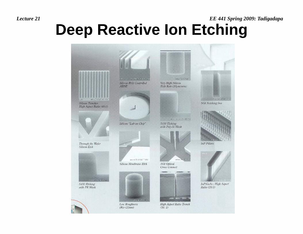
Deep Reactive Ion Etching

Lecture 21 EE 441 Spring 2009: Tadigadapa
Deep Reactive Ion EtchingDeep Reactive Ion Etching
Sequential Deposition of a Polymer Layer using Octofluorocyclobutane (C4F8) – a cyclic fluorocarbon that breaks open to form CF2 and longer chain radicals2 g
And
Etching of Silicon using Sulphur Hexafluoride (SF )Etching of Silicon using Sulphur Hexafluoride (SF6).

Lecture 21 EE 441 Spring 2009: Tadigadapa
DRIE Chamber
• High Density Plasma Source
i h h h i hRF Power
• High Throughput High Vacuum Pump
• Diffusion Chamber
Supply
DC Power Supply • Diffusion Chamber
• Cooled Substrate with variable positionp
• Separate Substrate Bias

Lecture 21 EE 441 Spring 2009: Tadigadapa
Aspect Ratio Dependent Etching• Narrow features etch slowly
compared to wider features duecompared to wider features due to:– Decrease in the radicals
il bilit d th hi h tavailability down the high aspect ratio feature
– Reduction in ions due to sidewall scattering, electrostatic scattering.
• Typical solution is to use aTypical solution is to use a buried passivation layer
• Over etching has to be carefully timed or else notching occurs

Lecture 21 EE 441 Spring 2009: Tadigadapa
Some of the Non-1Idealities in DRIE
1
Bottling Effect: Typically arises due to the use of high energy ions which tend to erode the side
ll i i i h b l h (1) Awall passivation causing the bottle shape (1). A better way to achieve higher anisotropy is to use longer etch times however, these resulting larger g g gsidewall roughness or scalloping (2).
2
Notching: Occurs due to the charging of the oxide buried layer which causes the ions to deflect towards the convex corner thereby breaking down
3
ow ds e co ve co e e eby b e g dowthe passivation and results in notching (3).
Lecture 21 EE 441 Spring 2009: Tadigadapa
Cryogenic Etching• Uses SF6 for etching using fluorine radicals• This process relies in forming a blocking layer of oxide/fluoride• This process relies in forming a blocking layer of oxide/fluoride
(SiOxFy) on the sidewalls around 10-20nm thick along with cryogenic temperature for inhibiting the sidewall attack.
• The low temperature operation also reduces the etch rate of the mask material since the attack by free-radicals is chemical in nature & therefore reduces with temperaturenature & therefore reduces with temperature.
• Process pressure is typically around 10 mTorr. The ion energy controlled by the substrate bias (RF) and ion density controlled by the ICP power are primary factors affecting the mask erosion. Measured DC bias values of less than 20V can give selectivity between silicon and oxide masks of over 750:1.selectivity between silicon and oxide masks of over 750:1.

Lecture 21 EE 441 Spring 2009: Tadigadapa
Gas Phase Etching•A non-plasma, isotropic dry etch process for silicon is possible using Xenon Difluoride (XeF2) and provides very high selectivity against silicon dioxide, stoichiometric silicon nitride, photoresist and g , , paluminum.•XeF2 is a white solid at room temperature and sublimates at 1 Torr. The etch reaction proceeds as:The etch reaction proceeds as:
2XeF2 + Si → 2Xe + SiF4where only silicon is in the solid phase. The reaction proceeds by non-dissociation adsorption of XeF2 at the silicon surface, dissociation of fluorine, and the reaction to form adsorbed SiF4 product and finally the desorption of the product and residual Xe.•Etch rates as high as 1-3 μm/min have been reported. However, the etched surfaces tend to be very rough and have a granular structure ~10 mm. Formation of silicon fluoride polymer can dramatically p y yslow or stop the etching process. Dehydration of the samples by baking can be used to avoid this problem.