DRS-WIN 4 Operation Manual - ANDRITZ · With this brief manual we realise what many of you wanted:...
41
Operation Manual DRS-WIN 4 PRT / SALN SID-401-1.XX/93.02 Edition: 21/01/2009 DRS-WIN4_Operation_Manual_with_suppl_e.doc page 1 /41 DRS-WIN 4 Operation Manual Revision: 2 Author: 29.09.2008 Salomon Approved: 29.09.2008 Schreiber First Edition: 26.01.2005
Transcript of DRS-WIN 4 Operation Manual - ANDRITZ · With this brief manual we realise what many of you wanted:...

Operation Manual DRS-WIN 4
PRT / SALN SID-401-1.XX/93.02
Edition: 21/01/2009 DRS-WIN4_Operation_Manual_with_suppl_e.doc page 1 /41
DRS-WIN 4
Operation Manual
Revision: 2
Author: 29.09.2008 Salomon
Approved: 29.09.2008 Schreiber
First Edition: 26.01.2005

Operation Manual DRS-WIN 4
PRT / SALN SID-401-1.XX/93.02
Seite 2 /41 DRS-WIN4_Operation_Manual_with_suppl_e.doc Edition: 21/01/2009
CAUTION
Installing, commissioning and operating of this product may be performed by thorough trained and
specialised personnel *
only. We explicitly will not take any responsibility for any damage on our products caused by improper installation, configuration and handling. Internal modifications must solely be carried out by specialised personnel authorised by
ANDRITZ HYDRO GmbH & Co * Definition: Specialised personnel, when authorised and properly instructed, may perform
following tasks: • Installing, mounting, commissioning and operating of the apparatus and the system
when familiar with. • Maintenance and use of safety equipment according to standard rules and regulations. • First Aid after extensive training.

Operation Manual DRS-WIN 4
PRT / SALN SID-401-1.XX/93.02
Edition: 21/01/2009 DRS-WIN4_Operation_Manual_with_suppl_e.doc page 3 /41
Contents: 1General Information.................................................................................................................. 5
1.1 Which DRS devices can be handled with DRS-WIN? ........................................................ 5
1.2 Why you should use DRS-WIN.......................................................................................... 5
1.3 User Interface.................................................................................................................... 5
1.4 Software version................................................................................................................ 6
1.5 Definitions ......................................................................................................................... 6
2First steps with DRS-WIN 4 ...................................................................................................... 7
2.1 Installing the software........................................................................................................ 7
2.2 Serial port cable ................................................................................................................ 8
2.3 Tool Bar........................................................................................................................... 10
2.4 DRS-Device window........................................................................................................ 11
3Configuration of DRS-Devices ............................................................................................... 12
3.1 Dealing with parameters and devices .............................................................................. 12
3.2 Password and Changing the Password ........................................................................... 13
3.3 Activate / Deactivate Protective Functions....................................................................... 14
3.4 Parameterization of Setting Values.................................................................................. 15
3.5 Adjustment of Function Inputs ......................................................................................... 15
3.6 Tripmatrix ........................................................................................................................ 16
3.7 LED-Matrix ...................................................................................................................... 17
3.8 CT- and VT-ratios............................................................................................................ 17
3.9 Plant specific denominations ........................................................................................... 18
3.10 Modified Data and the Reference File ........................................................................... 18
4Working Online ....................................................................................................................... 19
4.1 Display of Measured Values ............................................................................................ 19
4.2 Binary In- / Output Preset ................................................................................................ 19
4.3 System Time ................................................................................................................... 21
4.4 Fault Status ..................................................................................................................... 21
4.5 Fault Recorder................................................................................................................. 22
4.6 Event Recording.............................................................................................................. 25
5Supplement ............................................................................................................................. 26
5.1 Modifications of the appearance...................................................................................... 26
5.2 Program Toolbar ............................................................................................................. 27
5.3 Menu Item: DRS Functions ���� Configure Binary Input Matrix... ....................................... 28
5.4 Menu Item: DRS Functions ���� Configure Binary Output Matrix........................................ 28
5.5 Menu Item: DRS Functions ���� Configure Binary LED Matrix... ........................................ 29

Operation Manual DRS-WIN 4
PRT / SALN SID-401-1.XX/93.02
Seite 4 /41 DRS-WIN4_Operation_Manual_with_suppl_e.doc Edition: 21/01/2009
5.6 Menu Item: DRS Data ���� Load Fault Record From File... Menu Item: DRS Data ���� Load Fault Record From DRS... ................................................................................................ 30
5.7 Menu Item: Options ���� Select Language... ...................................................................... 32
5.8 Menu Item: Options ���� Program Options......................................................................... 33
5.9 Menu Item: DRS Functions ���� IEC103 Settings… Menu Item: DRS Functions ���� IEC104 Settings…......................................................................................................................... 33
5.10 Menu Item: DRS Data ���� Event Protocol... ���� Save Protocol ........................................ 36
5.11 Automatic Adjustments.................................................................................................. 37

Operation Manual DRS-WIN 4
PRT / SALN SID-401-1.XX/93.02
Edition: 21/01/2009 DRS-WIN4_Operation_Manual_with_suppl_e.doc page 5 /41
1 General Information
With this brief manual we realise what many of you wanted: a compact guidance of the general functions of DRS-WIN, the PC software for the control of the digital protection devices of the DRS-family. This description does not cover all aspects and functions of the DRS system control. Only the fundamentals of these are explained, so that you can work with DRS-WIN and your protective devices as soon as possible.
1.1 Which DRS devices can be handled with DRS-WIN? With the current version 4 of DRS-WIN you can handle all digital protective devices with only one software. DRS-MODULAR, DRS-COMPACT and DRS-LIGHT devices as well as the DRS-BB and DRS-C2BB devices for the bus bar protection are supported by DRS-WIN.
1.2 Why you should use DRS-WIN DRS-WIN enables you to program and handle your protective devices completely. You can do a lot of adjustments also directly at the protection panel (except DRS MODULAR), but most work procedures can be done with DRS-WIN faster and more clearly. For some tasks the software is however absolutely necessary, e.g. to initialise a spare part. Further DRS-WIN offers some features, e.g. binary In-/ Output simulation or to display measured operating values, that make the commissioning and maintenance of your plant easier.
1.3 User Interface DRS-WIN 4 runs on every Windows computer with Windows 98SE or higher. Mouse and keyboard are necessary for operation. DRS-WIN 4 manages one or more DRS devices in a program window, whereby each DRS device has its own window (the DRS-Device-Window) in the program window.
Program Window DRS-Device Window
Status Bar
Action L
ist
Connection Status
Tool B
ar
Info Bar Fig. 1 Program Window

Operation Manual DRS-WIN 4
PRT / SALN SID-401-1.XX/93.02
Seite 6 /41 DRS-WIN4_Operation_Manual_with_suppl_e.doc Edition: 21/01/2009
In the Action List all actions are logged. The active serial interfaces are listed with the appropriate connected DRS devices in the Connection Status window (see Fig. 1). In the Status Bar information about the serial communication is indicated. In the Tool Bar the most important instructions are available with one mouse-click. In addition, you can use the appropriate menu entry. Whenever you move with the mouse over a tool symbol, a supplementary text is indicated. Further important information is shown in the Info Bar (e.g. the connection establishment to DRS equipment).
1.4 Software version To find the version of your DRS-WIN please start DRS-WIN and click to menu "?" and "About DRS-WIN...":
If you need an upgrade, please visit our homepage or contact our support center in Vienna, Dept. PRT.
1.5 Definitions The following definitions are used within this document.
DRS-Device A digital relay system device
Program-Window The DRS-WIN main window. All other windows are within this window.
DRS-Device-Window Each DRS-Device has its own Device-Window. All device-specific actions, e.g. "Configure Trip Matrix ...", always refer to the active DRS-Device-Window.
Relay-Window Window in which the individual parameters of a protective relay (protective function) are listed. With protective relay the protective function is meant and not the physical DRS-Device, which can contain several protective functions.
Dialogue-Window A window, which expects a selection and/or a confirmation of the user.
DRS-File A file in that the entire configuration of DRS-Device is contained.

Operation Manual DRS-WIN 4
PRT / SALN SID-401-1.XX/93.02
Edition: 21/01/2009 DRS-WIN4_Operation_Manual_with_suppl_e.doc page 7 /41
2 First steps with DRS-WIN 4
2.1 Installing the software DRS WIN is running on all Windows 98SE, ME as well as Windows 2000 and WindowsXP versions. The following minimum requirements are recommended:
• Intel-Pentium3 or equivalent
• Main memory at least 128MB
• Colour screen with 1024x768 resolution at High-Colour
• Graphics card with 32MB memory or more
• At least 1GB free space on the hard disk
• CD-ROM drive to install DRS-WIN
• 1 free serial RS232 interface or USB interface with a special converter The DRS-WIN software is delivered on SETUP-CD. The setup program is started automatically after inserting the CD. If you deactivated the autostart function on your computer, double-click the file "Setup.exe" in the main folder of the installation CD. After the usual installation steps you must enter the provided serial code for DRS-WIN. A window opens as in Fig. 2. If you have acquired other programs (WinOper and SynWin), please also enter these serial codes into the appropriate fields.
Fig. 2 Installation
After the installation you see the DRS-WIN symbol on your desktop. In future you can start the program over this symbol, or directly in the installation folder selected by you.

Operation Manual DRS-WIN 4
PRT / SALN SID-401-1.XX/93.02
Seite 8 /41 DRS-WIN4_Operation_Manual_with_suppl_e.doc Edition: 21/01/2009
In the main folder some subfolders are created automatically during installation. The most important are:
Commissioning Measurement files are saved in this folder.
Funcdefs Contains the so-called function-definition-files; they include all relevant data about the protection function.
Hist Contains the fault record files
Plants Contains the DRS parameter files (which fully defines the function of a DRS device)
Refs Reference files are used to save changes to older versions of DRS parameter files
This listing structure should not be changed, however you can save your parameter files also into any other folder. If you copy the program for any reasons (exchange of the control device, etc..), then make sure that also the entire folder structure is copied. If you got DRS WIN 4 installed on a notebook, you can transfer the program in this way to another computer, without losing any attitudes or parameter files. Note: For reasons of the data consistency during the operation, we recommend to use the given folder structure and to use different folders only in exceptional cases. In case of using different folders the user has to ensure very carefully that the valid files will be transferred in each case from and to the correct storage medium.
2.2 Serial port cable For an online connection with a DRS you need an interface cable which must be attached to a free serial interface. If you did not get an interface cable, please contact us (to contact address see page 40) and/or to the supplier of your DRS equipment. If your PC has no free serial port you need a USB/ RS-232 converter. For the DRS MODULAR and DRS COMPACT a fibre optics cable provides potential separation between the DRS and PC. For the device-sided connection a 9-pole sub-D-plug is used. The connection plug is on the front side of the DRS-COMPACT and/or DRS-MODULAR. At DRS LIGHT potential separation is integrated. The optional available DRS-LIGHT cable connection can be directly connected to the screw connectors, which are at the back of the device. After plugging in the cable and starting the DRS-WIN software the communication is established automatically.

Operation Manual DRS-WIN 4
PRT / SALN SID-401-1.XX/93.02
Edition: 21/01/2009 DRS-WIN4_Operation_Manual_with_suppl_e.doc page 9 /41
Starting DRS-WIN 4 With the interface cable you connect the PC with the protection device. Start DRS-WIN with a double click at the DRS-symbol on the desktop. The program will now search for connected devices.
Fig. 3 Searching for devices
You can cancel this process if you want to work offline (see Fig. 3). With the offline mode you can only load and configure DRS-files. Use this mode if you only want to view DRS-files or if you are not so experienced with DRS-WIN. Then you avoid mistakes that can cause problems in the online mode (also see 4.2 Binary In- / Output Preset). When a device was found a dialogue window opens like in Fig. 4. Click onto "Continue".
Fig. 4 Establish connection
The data will be downloaded from the device and the relay window opens. The DRS-WIN is now in the Online Mode. Attention! Please do not use any other possibility for the connection to the device than the ones described above because it could be possible that the old parameters could unintentionally be erased. We recommend to read that operation manual completely before working with the protection device in the Online Mode.

Operation Manual DRS-WIN 4
PRT / SALN SID-401-1.XX/93.02
Seite 10 /41 DRS-WIN4_Operation_Manual_with_suppl_e.doc Edition: 21/01/2009
In case the communication was not established the following items should be checked:
• Did you use the correct interface cable?
• Is the DRS protection relay switched on? Also check the configuration of the interfaces in the DRS-WIN. In the menu "Communication" submenu "Communication ports" you reach the following window. Check whether the correct port is activated. Select for the used interface port the profile name "All" and confirm with "OK".
Fig. 5 Configure serial ports
2.3 Tool Bar The tool bar is to be found in the DRS-WIN program window underneath the menu bar.
Open DRS file
Enter Password
Show primary values
Show relative values
Show secondary values
Fig. 6 Tool Bar
With the symbol "Open DRS file" it is possible to load and adjust DRS files or the parameterisation of a DRS device can be revised. By means the symbols "Show ... values" you can select in which kind of values the DRS-WIN indicates its measured values. Please remark that the secondary values are actually used for the setting of the protective functions. The displayed primary values correspond to the secondary values multiplied by the adjusted ratio. The relative values correspond to the primary values in percent to the nominal value of the protected object. That selection has an effect on all the DRS-windows indicating the measured values that are available online and can be changed under operation. By changing the indicated values of all windows at the same time confusion because of different kinds of values can be avoided.

Operation Manual DRS-WIN 4
PRT / SALN SID-401-1.XX/93.02
Edition: 21/01/2009 DRS-WIN4_Operation_Manual_with_suppl_e.doc page 11 /41
2.4 DRS-Device window In the device window we can see all the activated protective functions and the indication of the connection status (online or offline). By the icons in the device window we also have access to the most important measured values and the settings of the device.
Change trip matrix
Change LED matrix Show measured values
Print all DRS dataSystem time
Event list Fault recorderDevice online
Fig. 7 Device Window
With the printer symbol the complete parameter set can be printed for a quick documentation. The Trip- and the LED-matrix can be changed by use of the corresponding icons (refer to 3.6 Tripmatrix). To view the measured values you have to click on symbol with the meter. All the currents and voltages that are measured by the protection relay are then displayed. Information about the saving of all the device data you can find by the diskette symbol you can find on the following pages. All other symbols in the device window will also be described in the following (refer to Fig. 9 DRS-, Fig. 25 and Fig. 28 ).

Operation Manual DRS-WIN 4
PRT / SALN SID-401-1.XX/93.02
Seite 12 /41 DRS-WIN4_Operation_Manual_with_suppl_e.doc Edition: 21/01/2009
3 Configuration of DRS-Devices
3.1 Dealing with parameters and devices The DRS-WIN simplifies the storage of your digital protection relays. There is everywhere a common concept to be found for all DRS protection relays, whether or no DRS-LIGHT, -COMPACT or DRS-MODULAR devices are used. For each device a unique so-called DRS-file is used that describes the basic parameters and the setting values of the device completely. The designations of the in-/ outputs and all other text are captured completely, too. The DRS-file that is stored on the operation computer defines the parameters of one DRS-device completely. For that reason the data cannot be lost. In case of a damage of one DRS-device you can still configure a spare part by use of one single file. And in case of a damage of the operation computer it is possible to download all data of the DRS-protection device when there is a standard installation available on any other computer.
DRS file
Reference file
Laptop
RAM
DRS-LIGHTOperation computer
RS-232 / RS-485
Hard
Disk
Fig. 8 Working with DRS-Files
When connecting to the DRS-device the parameters of the device are captured by the DRS-WIN (so the parameters are located in the RAM of the operation computer). To save the actual parameters as a file you have to activate the icon "Save data" in the DRS-device window (refer to Fig. 7). The DRS-file is then located in the directory "Plants" (refer to 2.1). When changing the parameters in the DRS-WIN only the data in the RAM of the computer is modified. Only when activating the icon "Send all data to DRS" the data will be captured by the DRS-device. Save the parameters that are displayed on the DRS-WIN for your further use in the offline mode. In case of any doubt about the actual state of the parameters you can download the parameters from the DRS protection relay to the operation computer as only the data stored in the protection relay is of relevance. By a mouse-click on the symbol "Read all data from DRS" in the device window you can download all the data. The filenames of the DRS-files in the directory "Plants" always have the same structure.
DRS_xxxx.VE
Whereby xxxx is the device denomination. For x all alphanumerical symbols can be used with the exception of special symbols. Please be aware that the denomination has to be clear and unequivocal. A combination of four signs like "G132" is allowed only for one time per project, otherwise a clear storage of the DRS-files would not be possible.

Operation Manual DRS-WIN 4
PRT / SALN SID-401-1.XX/93.02
Edition: 21/01/2009 DRS-WIN4_Operation_Manual_with_suppl_e.doc page 13 /41
Safe all data
Send all data to DRS
Read all data from DRS
DRS online
Device Identification Changes to reference
Fig. 9 DRS-Files and the Device Window
Please be aware that when opening a DRS-file of a device that is already displayed in the Online mode the displayed data of the device will be replaced by the data of the DRS-file. Only the parameters in the display will be replaced, to replace the data stored in the DRS-device you would have to send the data to the DRS-device.
3.2 Password and Changing the Password For each modification of the parameters of a DRS-device the DRS-WIN requires a password. This is to avoid that the parameters are changed unintentionally. The password is individually selectable for each DRS-device and is stored in the DRS-file and in the device.
Fig. 10 Change Password

Operation Manual DRS-WIN 4
PRT / SALN SID-401-1.XX/93.02
Seite 14 /41 DRS-WIN4_Operation_Manual_with_suppl_e.doc Edition: 21/01/2009
The default password of the DRS-LIGHT is "a". For the DRS-MODULAR and DRS-COMPACT the default password is "drs" or "a" as well. If occasion arises please change the password. The password should prevent that unauthorised persons carry out modifications on the protection relays. So only authorised persons should have knowledge of the passwords. To change the password you have to press the icon with the "padlock". The window to enter the password appears. Do not fill in the password but press as indicated in Fig. 10 the button "Change password...". Now you have to fill in the old password and underneath twice the new password (twice the same for confirmation). The new password is now active, for the storage of the new password in the DRS-device you have to send all data to the device (by means of the button "Send all data to DRS" in the device window) and save the parameters on the operation computer (by means of the button "Save data"). Please store the passwords of your protection devices carefully because it is not possible to change parameters without valid password. In case of loss of the password of one of your DRS-relays we ask you to contact us (refer to page 25).
3.3 Activate / Deactivate Protective Functions The protective functions are configured before delivery. Nevertheless it is possible to deactivate protective functions by activating a device window, in the menu "DRS Functions" you have to press the menu "Selection Of Active Functions".
Fig. 11 Activate Protective Functions
A window opens where you can activate or deactivate the protective functions. To deactivate a certain protective function could be useful when testing the protection relay. Furthermore in some cases it is possible to configure the protection relay of one project with a greater number of similar protective functions, like definite time and inverse time overcurrent, if necessary it is possible to select the required function.
Operation Manual DRS-WIN 4
PRT / SALN SID-401-1.XX/93.02
Edition: 21/01/2009 DRS-WIN4_Operation_Manual_with_suppl_e.doc page 15 /41
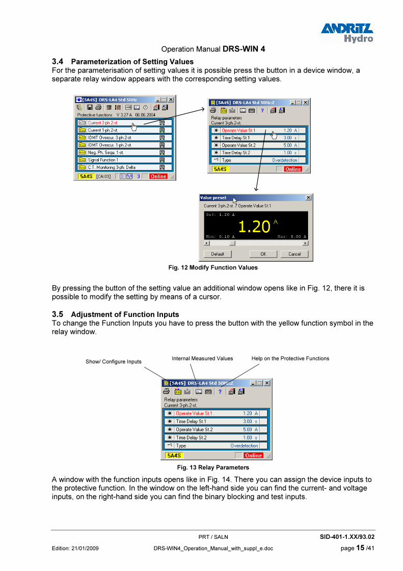
3.4 Parameterization of Setting Values For the parameterisation of setting values it is possible press the button in a device window, a separate relay window appears with the corresponding setting values.
Fig. 12 Modify Function Values
By pressing the button of the setting value an additional window opens like in Fig. 12, there it is possible to modify the setting by means of a cursor.
3.5 Adjustment of Function Inputs To change the Function Inputs you have to press the button with the yellow function symbol in the relay window.
Show/ Configure InputsInternal Measured Values Help on the Protective Functions
Fig. 13 Relay Parameters
A window with the function inputs opens like in Fig. 14. There you can assign the device inputs to the protective function. In the window on the left-hand side you can find the current- and voltage inputs, on the right-hand side you can find the binary blocking and test inputs.

Operation Manual DRS-WIN 4
PRT / SALN SID-401-1.XX/93.02
Seite 16 /41 DRS-WIN4_Operation_Manual_with_suppl_e.doc Edition: 21/01/2009
Fig. 14 Change Function Inputs
3.6 Tripmatrix For modifications in the tripmatrix you have to press the button with the symbol of the tripmatrix in the device window. (refer to Fig. 7). By a mouse click on the corresponding connection in the tripmatrix it is possible to activate or deactivate it. On the left-hand side of the window the alarm- and trip outputs of the protective functions are visible that can be connected to the output relays on the topside of the window. The selected connection is highlighted yellow. Please remark that with the change an additional danger symbol and a circle around the changed connection point will be visible.
Fig. 15 Changing the Trip Matrix

Operation Manual DRS-WIN 4
PRT / SALN SID-401-1.XX/93.02
Edition: 21/01/2009 DRS-WIN4_Operation_Manual_with_suppl_e.doc page 17 /41
3.7 LED-Matrix The LED-Matrix can be changed like the tripmatrix. A point defines a connection from the alarm- or trip output of a function to the respective LED. Please remark that the yellow LEDs are normally used for alarms, the red LEDs are normally used for trips.
Fig. 16 Changing the LED-Matrix
3.8 CT- and VT-ratios The measured values can be displayed in primary values, relative values or secondary values (refer to 2.4 DRS-Device window). To display the primary or relative values correctly the CT- and VT-ratios have to be filled into the list below. Press the "CT/VT settings" in the menu "DRS Functions", the following window opens:
Fig. 17 Specification of CT and VT ratios

Operation Manual DRS-WIN 4
PRT / SALN SID-401-1.XX/93.02
Seite 18 /41 DRS-WIN4_Operation_Manual_with_suppl_e.doc Edition: 21/01/2009
3.9 Plant specific denominations It is possible to modify the plant specific denominations. So it is possible to change for example the names of the binary inputs. In the menu "DRS Functions" press "Plant Specific Denominations", the following window opens:
Fig. 18 Modify Denominations
After changing the denominations the complete setting file has to be loaded to the protection relay (press the symbol "Send All Data To DRS" in the device window).
3.10 Modified Data and the Reference File With the very first downloading of the parameters from a protection relay the DRS-WIN creates automatically a reference file. That file contains like the DRS-parameter file all settings of one DRS. In case of changes of settings the DRS-WIN compares the new settings with the reference file. The danger symbol (on the bottom of the device window) indicates that there exists a difference between the setting file and the reference file. To accept the changes of the reference file you have to press the danger symbol, a dialogue window opens like in Fig. 19. There you can see which kind of parameter was changed. With the button "Save reference file" it is possible to accept the changes, the danger symbol disappears in the device window.
Fig. 19 Changes to the Reference-File
We recommend saving the reference file after the commissioning of the protection relay.

Operation Manual DRS-WIN 4
PRT / SALN SID-401-1.XX/93.02
Edition: 21/01/2009 DRS-WIN4_Operation_Manual_with_suppl_e.doc page 19 /41
4 Working Online
4.1 Display of Measured Values To display the measured values you have to click the symbol with the meter in the device window. A window as below appears, the blinking red arrows indicate the measured value is refreshed.
Display sizeSave as text file
Fig. 20 Measured Values
To save the measured values press the symbol "Save as text file". The measured values are then stored in a text file in the directory "Commissioning". The file (like DRS-5P8S.tpc) has the extension "tpc", it is possible to open the file with any text editor.
4.2 Binary In- / Output Preset To activate the binary in- and outputs of the protection relay during commissioning or testing you require the "Binary In- / Output Preset". There you can define the state of the binary in- or outputs. It is also possible to monitor the actual state of the in- or outputs. To open the Binary In- / Output Preset select in the menu "System" the "Binary In- / Output Preset". A window like in Fig. 21 appears. There you can select the required state of the in- or output, with the button "Apply" the state will be set until "Regular Function" and "Apply" or "OK" is selected. The difference between these two buttons is that with "OK" the window will be closed whereby with "Apply" the window remains open. In case the window of the Binary In- / Output Preset is closed all the in- and outputs are set to "Regular Function" automatically. The same happens in case the interface cable is removed. This is to avoid unintentional setting of binary in- or outputs during testing.

Operation Manual DRS-WIN 4
PRT / SALN SID-401-1.XX/93.02
Seite 20 /41 DRS-WIN4_Operation_Manual_with_suppl_e.doc Edition: 21/01/2009
Fig. 21 I-/O Preset
Please remark that all devices like circuit breakers can be tripped directly with the Binary In- / Output Preset. That requires a certain knowledge of the system. In case of tests you should use a protection relay that is not connected to the primary system or ensure that the primary system is not in operation.
Fig. 22 I/O Preset

Operation Manual DRS-WIN 4
PRT / SALN SID-401-1.XX/93.02
Edition: 21/01/2009 DRS-WIN4_Operation_Manual_with_suppl_e.doc page 21 /41
4.3 System Time All DRS devices have an internal system time. With all recordings in the event records or fault records the system time is displayed. Each DRS device has its own system time that starts its operation when the protection relay is energised. There exist different methods to synchronise the internal system time with a reference time. Independent from the method that is used in your system it is also possible to set the internal system time manually. To synchronise the internal system time of the protection relay with the time of the PC you have to press the icon with the clock symbol in the device window. The following window opens:
Synchronize clocks
Fig. 23 Synchronise System Time with PC Time
The actual internal DRS system time is displayed. That time stamp is used for the fault- and event recordings. In case the DRS system time is not correct it is possible to set the DRS system time according to your PC by pressing the icon "Synchronise clocks".
4.4 Fault Status DRS devices monitor permanently their function and the elements of their periphery (like auxiliary transformers). The result of the self supervision is indicated by LEDs on the device and by a message in the event recordings. A more exact fault determination is possible with the DRS-WIN. In case of an internal fault the details can be achieved as described in the following. Press onto the calling symbol on the bottom of the device window. A window opens with the details of the internal fault like in the following figure:
Fig. 24 DRS Fault Status
An exact description of the individual faults and their causes can be found in the "DRS-Operation Manual". Please remark that not each fault means a defect of the DRS-device (i.e. CT-/VT-failure). A DRS-fault means that not the complete protection is available. It is up to the operator to decide whether the system can be operated while neglecting the alarm of the DRS.

Operation Manual DRS-WIN 4
PRT / SALN SID-401-1.XX/93.02
Seite 22 /41 DRS-WIN4_Operation_Manual_with_suppl_e.doc Edition: 21/01/2009
4.5 Fault Recorder For each pickup of a protective function a fault recording can be triggered. With the "tape symbol" in the relay window it is possible to select whether a pickup triggers the fault recording or not.
Fig. 25 Trigger condition for Fault Recorder
In case a fault was recorded or in case fault recordings are stored in the DRS device the symbol of an oscillogram appears on the bottom of the device window. The number in the area beside the symbol of the oscillogram indicates how many recordings are stored in the DRS device. To download the fault recordings you have to click onto the oscillogram symbol. A dialogue window opens like in the following figure.

Operation Manual DRS-WIN 4
PRT / SALN SID-401-1.XX/93.02
Edition: 21/01/2009 DRS-WIN4_Operation_Manual_with_suppl_e.doc page 23 /41
Fig. 26 Read Fault Record
Select a fault record and press the button "Read fault record". Now the fault recording is downloaded from the DRS device to your PC that can take some time. It is possible to cancel the downloading without losing the downloaded data. To save a downloaded fault recording you have to press the disc symbol in the window of the fault recordings.

Operation Manual DRS-WIN 4
PRT / SALN SID-401-1.XX/93.02
Seite 24 /41 DRS-WIN4_Operation_Manual_with_suppl_e.doc Edition: 21/01/2009
Fig. 27 View Fault Records
Saved recordings are stored in the directory "Hist", they are stored in the COMTRADE-format. The filename contains the denomination of the device and the time stamp of trigger moment (that is the beginning of the operation of the function) of the specific fault recording. That filename is created automatically by the DRS-WIN. For each fault recording three files are stored in the directory "Hist", they have the extensions "CFG", "DAT" and "HDR". You require all three files to open the fault recording with a COMTRADE Viewer. The filename contains the following important information:
G221.2004-08-18 10-03-02-053.dat
Device Identifier Date Time
Moment of Trigger

Operation Manual DRS-WIN 4
PRT / SALN SID-401-1.XX/93.02
Edition: 21/01/2009 DRS-WIN4_Operation_Manual_with_suppl_e.doc page 25 /41
4.6 Event Recording All pickups and trips can be stored in the event recording. Each activation results in one record with the exact internal DRS system time. By pressing the "tape symbol" in the relay window you can select whether an event recording shall be started or not.
Fig. 28 Event List
The records can be stored in a file by pressing the disc icon. The stored "TRP" file can be found in the directory "EventLists" and can be opened with any text editor. The file names for the event recordings are created automatically by the DRS-WIN and contain the relay denomination and the time when the event record was stored.
# 0d 00h 00m 00s:000 Restart after Hardwarereset
# 0d 00h 00m 00s:000 DRS fault: <-12V Supply Voltage Error>
# 0d 00h 40m 48s:425 Start of new parameter setting
# 0d 00h 41m 02s:890 End of new parameter setting
# 0d 00h 41m 35s:174 Signal Function 1 Alarm Come
# 0d 00h 41m 35s:174 Signal Function 1 Trip Come
# 0d 00h 41m 39s:012 Signal Function 1 Alarm Go
# 0d 00h 41m 39s:012 Signal Function 1 Trip Go
# 0d 00h 41m 39s:012 end of failure
Fig. 29 Content of Event File

Operation Manual DRS-WIN 4
PRT / SALN SID-401-1.XX/93.02
Seite 26 /41 DRS-WIN4_Operation_Manual_with_suppl_e.doc Edition: 21/01/2009
5 Supplement
The first-edition of the short-instruction of the operating software DRS-WIN4 was released in the year 2004. Since then, the software was modified several times so that a supplement of the short-instruction is necessary. In this supplement, new system-features of the DRS-devices and their engineering with DRS-WIN are described. Please be aware, that these new features are not available with all types of devices and only from certain firmware-versions of apparatus. This supplement is applicable to versions of DRS-WIN4 from Build 2360.
5.1 Modifications of the appearance A multiplicity of the modifications concerns the optical appearance and the usability of the program, but however, the philosophy of handling was not changed and is still valid as described in the existing short-instruction. As example for the new optics, no more colour-changes now are done in the windows, but each online-window is marked by a red frame, that is to be recognized clearly and better as the old representation, also with partial overlapping of the windows.
Fig. 30: DRS-Device Window
Also under menu-point "System, LED Status". the display of the LED-windows now are indicated how they correspond to the real view at the respective apparatus.
Fig. 31: LED Status Window
Selection
"Binary I/O Preset"
Selection "Function Outputs"

Operation Manual DRS-WIN 4
Edition: 21/01/2009
5.2 Program Toolbar Some symbols in the toolbar of the program-window were not specified in the first description and have to be explained in this supplement.
In detail to explain is the funcworkspace" the arrangement stored (please note, that the IOperating the button "Restoreselected device, if previously At the practical working with Dshown on the desktop. If the above described process "SaTo restore the arrangement orepeated per device.
Load disturbance record
View text file
Search
ices
Modem connection
Save workspaceDRS-WIN4
Fig
tion of theof the winD of this d workspastored. RS-WIN,
user now wve workspf the wind
Restore workspace
dev
PRT / SALN SID-401-1.XX/93.02
_Operation_Manual_with_suppl_e.doc page 27 /41
. 32: Program Toolbar
"workspace" in this context. By operating the button "Save dows of that device, that is processed currently, will be evice is shown on the top of the program-window). ce" restores the arrangement of the windows of the
depending on the type of connection, several devices are ants to store the workspace for all appliances, so the
ace" must be repeated for each device. ows for all devices, the restore procedure is to be
Telnet connection

Operation Manual DRS-WIN 4
PRT / SALN SID-401-1.XX/93.02
Seite 28 /41 DRS-WIN4_Operation_Manual_with_suppl_e.doc Edition: 21/01/2009
5.3 Menu Item: DRS Functions ���� Configure Binary Input Matrix... Before introduction of the binary input matrix, assignments between the binary inputs of the device and the binary protective function inputs were only possible in the sub-window "protective function inputs" in the respective protection function "Relay parameters" window. The binary input matrix now offers a total overview over all connections between the protective functions binary inputs arranged in the matrix-rows and the binary inputs on the apparatus in the matrix-columns. The operation of the binary input matrix is in same manner as with the other connection-matrices. The assignment procedure now is possible by both methods, the old via setting in the different protective functions or via the new binary input matrix as well. Additionally for certain device-types or firmware-versions the binary input matrix offers the possibility, to invert the polarity of a binary input signal. Not available and thus not assignable binary inputs are faded out in the binary input matrix.
Fig. 33: Configure binary input matrix.
5.4 Menu Item: DRS Functions ���� Configure Binary Output Matrix... At this menu item, not only the connections between the protective function outputs and the binary outputs of the device (output-relays) are selected, but also some new attributes of the binary outputs are now available. Every binary output can be inverted alternatively. Additionally, a minimum output-pulse-extension can be set for every binary output. For all selected outputs this minimum-impulse-extension can be set by the parameter "output pulse extension" in a range between 0 and 10 seconds. Not available and thus not assignable binary outputs are faded out in the binary input matrix.

Operation Manual DRS-WIN 4
PRT / SALN SID-401-1.XX/93.02
Edition: 21/01/2009 DRS-WIN4_Operation_Manual_with_suppl_e.doc page 29 /41
Fig. 34: Configure binary output matrix.
5.5 Menu Item: DRS Functions ���� Configure Binary LED Matrix... The mode of operation of the LED-indications of the apparatus can now per LED be selected from 3 modes. Mode: Hand reset All LED-indications since the last reset of the LED (or power-up) are displayed cumulated till the next manual reset. Mode: Self reset LEDs with this mode only remains ignited as long as the reason for operation of the LED persists. Mode: Action reset All LED indications with this mode are displayed cumulated for a certain time. For DRS-LIGHT devices this time corresponds with the duration of a disturbance record. At DRS-COMPACT this time can be selected separately via the parameter "Action reset timeout". After this time has expired, at the start of the next disturbance event the LED are reset.

Operation Manual DRS-WIN 4
PRT / SALN SID-401-1.XX/93.02
Seite 30 /41 DRS-WIN4_Operation_Manual_with_suppl_e.doc Edition: 21/01/2009
Fig. 35: Configure LED matrix.
5.6 Menu Item: DRS Data ���� Load Fault Record From File... Menu Item: DRS Data ���� Load Fault Record From DRS...
The recorded curves of the current- and voltage-transformer signals can now be shown also in phasor-diagram-representation. In principle, a phasor-diagram 1 and 2 is produced for the position of each cursor, but however depending on the space on the desktop available for phasor-diagrams sometimes only the phasor-diagram for cursor 1 is shown. By sliding of the cursor, the phasor-diagram at the time of interest can be selected. At the print-out of a disturbance record always both phasor-diagrams are printed, if phasor-diagram is selected in the display of the disturbance record. The disturbance record-visualisation can be selected between display in secondary-values, relative-values and primary-values. At the representation in primary-values, a seperate scale can now be selected for each signal.

Operation Manual DRS-WIN 4
PRT / SALN SID-401-1.XX/93.02
Edition: 21/01/2009 DRS-WIN4_Operation_Manual_with_suppl_e.doc page 31 /41
Fig. 36: Disturbance record with phasor-diagram in secondary-value-representation
Fig. 37: Disturbance record with phasor-diagram in primary-value-representation

Operation Manual DRS-WIN 4
PRT / SALN SID-401-1.XX/93.02
Seite 32 /41 DRS-WIN4_Operation_Manual_with_suppl_e.doc Edition: 21/01/2009
To simplify analyzing of the disturbance record, now under "Settings of Fault Recorder Display" via the button "Search for Binary Tags" all binary tags, which change their value during the disturbance, are selected for display in the Binary I/Os column.
Fig. 38: Settings of the Fault Recorder Display
In "Settings of the Fault Recorder Display" under "Fault Recorder Colours" now the background-colour and the grid-lines for the print-out of the disturbance record can be selected independent of the display on the screen. Via the button "Use as Default" these settings are applied to all other disturbance records.
5.7 Menu Item: Options ���� Select Language... At this menu item, the DRS-WIN program-language can be selected from the languages available (Standard: German and English)
Fig. 39: Language-selection

Operation Manual DRS-WIN 4
PRT / SALN SID-401-1.XX/93.02
Edition: 21/01/2009 DRS-WIN4_Operation_Manual_with_suppl_e.doc page 33 /41
5.8 Menu Item: Options ���� Program Options... Different parameters of this menu item are adjustable for the perfect function of DRS-WIN. The default-values set at the program-installation as well as the values chosen by our experts during commissioning in general are optimized for the configuration and should not be changed without any reason. Please write down the old value before changing of a parameter so that you can restore the old configuration again at least.
Fig. 40: Program Options
5.9 Menu Item: DRS Functions ���� IEC103 Settings… Menu Item: DRS Functions ���� IEC104 Settings…
At these items, the parameters for communication via IEC60870-5-103/104 protocol are adjustable. Since the engineering for IEC 60870-5-104, due the much higher functionality and capability, is more extensively than for IEC 60870-5-103 and not to overload this short description, only the principles of engineering the IEC 60870-5-103 protocol interface are described in this supplement. The engineering of IEC 60870-5-104 is identically built from the principle, so it can be applied analogously. At appliances, that don't make available these communication protocols, the above menu items are not enabled.
Operation Manual DRS-WIN 4
PRT / SALN SID-401-1.XX/93.02
Seite 34 /41 DRS-WIN4_Operation_Manual_with_suppl_e.doc Edition: 21/01/2009
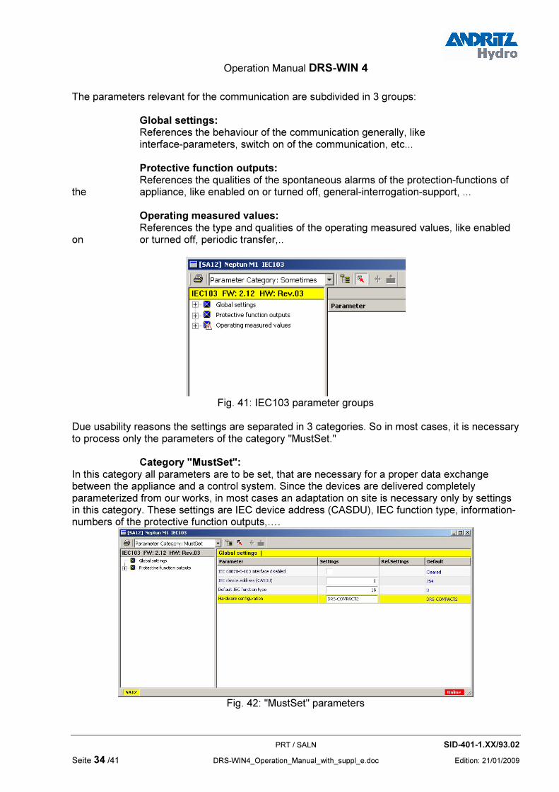
The parameters relevant for the communication are subdivided in 3 groups: Global settings: References the behaviour of the communication generally, like interface-parameters, switch on of the communication, etc... Protective function outputs: References the qualities of the spontaneous alarms of the protection-functions of the appliance, like enabled on or turned off, general-interrogation-support, ... Operating measured values: References the type and qualities of the operating measured values, like enabled on or turned off, periodic transfer,..
Fig. 41: IEC103 parameter groups
Due usability reasons the settings are separated in 3 categories. So in most cases, it is necessary to process only the parameters of the category "MustSet." Category "MustSet": In this category all parameters are to be set, that are necessary for a proper data exchange between the appliance and a control system. Since the devices are delivered completely parameterized from our works, in most cases an adaptation on site is necessary only by settings in this category. These settings are IEC device address (CASDU), IEC function type, information-numbers of the protective function outputs,….
Fig. 42: "MustSet" parameters

Operation Manual DRS-WIN 4
PRT / SALN SID-401-1.XX/93.02
Edition: 21/01/2009 DRS-WIN4_Operation_Manual_with_suppl_e.doc page 35 /41
Category "Frequent": The parameters of this category are used additionally, when changes in some global parameters or some attributes in the protective function outputs are necessary or to enable the transfer of disturbance records.
Fig. 43: "Frequent" parameters
Category "Sometimes": In this parameter-category, all parameters can be changed completely in all details.
Fig. 44: "Sometimes" parameters
Please note, that inconsistent parameters are detected and an error message "IEC103-PARA-ERR. SETUP REQUIRED" on the device display is shown as well as the entry "SIP software-mistakes" in the event-protocol is set. Such an inconsistence may happen for example, if the transfer of the operating measured values was activated, but the transfer of every individual value again was disabled. This error lasts as long as the inconsistence has not been removed by changing of the parameters involved. The operation of the protection-functions itself is not influenced by this error. In the column "Settings" the current values of the respective parameters are displayed, the column "Ref. Settings" shows the values of the parameters as stored for reference (please note the change indications at the parameters). The column "default" shows the values of the respective parameters which causes the lowest burden for the communication-system and it is recommended, to select these values temporary, as far as technically reasonable, when making troubleshooting for some general problems in the communication system. Setting of the parameter can generally happen via an input-window (as usual in DRS-WIN). Parameter changes with respect to the original values, as usual in DRS-WIN, are indicated

Operation Manual DRS-WIN 4
PRT / SALN SID-401-1.XX/93.02
Seite 36 /41 DRS-WIN4_Operation_Manual_with_suppl_e.doc Edition: 21/01/2009
through by the known warning-signs. For further information about type and meaning of the parameters please consult the corresponding standards (IEC 60870-5-103, IEC 60870-5-104) as well as separate descriptions of ANDRITZ HYDRO GmbH.
5.10 Menu Item: DRS Data ���� Event Protocol... ���� Save Protocol At these menu items readout and storing of an event-protocol from a DRS-device is managed. When storing an event-protocol, CSV-files are stored into different subdirectories on the operating-PC. In the subdirectory "Data/EventLists" of the DRS-WIN program-directory is stored a file named "XXXX.JJJJ-MM-TT HH-NN.csv". In this file name means: XXXX Device-ID of the relevant DRS-appliance JJJJJ-MM-TT HH-NN Time when saved
Fig. 45: Folder EventLists
Fig. 46: Stored event-protocols
In the subdirectory "Data/Pdm" the entries of the event-protocol will be sorted according the date of the entry in additional subdirectories of year and month, into a CSV-file with the file name of the date of the entry. By this, all entries of all event-protocols are sorted by day in chronological order.
Fig. 47: Folder Pdm

Operation Manual DRS-WIN 4
PRT / SALN SID-401-1.XX/93.02
Edition: 21/01/2009 DRS-WIN4_Operation_Manual_with_suppl_e.doc page 37 /41
Fig. 48: Day-summaries
If the event-protocols from several appliances are stored, these day-summaries deliver a total-overview over all events in chronologically sorted order. MS Excel can read CSV-files and can process these data further.
5.11 Automatic Adjustments The system-properties and the reliability of the DRS-devices are expanded and improved continuously. These new properties require system-entries into the parameter-file, that didn't exist in in the parameter file when made by former versions of DRS-WIN. However, in general DRS-WIN can collect the necessary information for these entries from other sources and all necessary adaptations are done completely automatically. These "Automatic Adjustments" are displayed in an information window as below.
Fig. 49: Information About Automatic Adjustments
In order to accept these adaptations and store them into the appliance permanently, press "OK" to accept the changes and overwrite the old parameter file with this new one on your PC and send the new data to the appliance too. In rare cases it is also possible, that DRS-WIN detects some minor inconsistencies (connection mismatch) in the parameter file, although the device is fully functional.

Operation Manual DRS-WIN 4
PRT / SALN SID-401-1.XX/93.02
Seite 38 /41 DRS-WIN4_Operation_Manual_with_suppl_e.doc Edition: 21/01/2009
Fig. 50: Connection Mismatch
In order to correct this minor inconsistency, please assign the indicated signal to the proper I/O channel.
Fig. 51: Connection mismatch correction
In the very rare cases, DRS-WIN cannot make the necessary adoptions automatically. In such cases the user must specify the actual configuration in accordance with the "System Configuration Request" window below. The selection of the options to be entered normally can be decided by simple visual inspection. Is there no local display and keyboard (terminal) existing in the relay front, select "No terminal". At existing terminal, select the option "Terminal", look for the version of terminal as per the appropriate manual of the device and set the version in the "System Configuration Request" window accordingly.
Fig. 52: System Configuration Request

Operation Manual DRS-WIN 4
PRT / SALN SID-401-1.XX/93.02
Edition: 21/01/2009 DRS-WIN4_Operation_Manual_with_suppl_e.doc page 39 /41
After this, the adaptations done from the operating software DRS-WIN, are displayed again in an information window as below. To make this changes permanent, press "OK" to accept the changes and overwrite the old parameter file with this new one on your PC and send the new data to the appliance too.
Fig. 53: Information About Automatic Adjustments
We recommend to accept the configuration adoptions made by DRS-WIN and to make these permanently. If these adaptations are not accepted permanently, the entire sequence described under "Automatic Adjustments" like above starts again, when reading parameters again from file or from the device.

Operation Manual DRS-WIN 4
PRT / SALN SID-401-1.XX/93.02
Seite 40 /41 DRS-WIN4_Operation_Manual_with_suppl_e.doc Edition: 21/01/2009
COPYRIGHT, REMARKS
This document is the sole property of ANDRITZ HYDRO GmbH and may neither be copied nor distributed and used without our written consent. Law according to DIN 34 Standard will prosecute violations. The data contained in this literature should be considered as product information only. We would like to advise that short term modifications of our production range are possible due to our aim to continuously improve the performance of our products for the benefit of our customers so there may be differences between the products supplied and the corresponding descriptive literature. According to our experience following the instructions outlined in this document will provide the most satisfactory service performance. In case of unusual troubles, which cannot be resolved by referring to this literature, please contact our nearest agent or our Head Office. When commissioning, the operating instructions and also the applicable Local Safety Standards have strictly to be observed. This edition of the document has been carefully checked regarding up-to-date contents and correctness. Should there be any discrepancies or contradictory information in this descriptive literature, could you please inform us. In case of problems please do not try to solve them on your own but contact our nearest agency or our Head Office, which will be glad to be of any assistance to you. All agreements, legal rights, obligations, performance and scope of supply for ANDRITZ HYDRO GmbH and also conditions, governing the warranty, are without expectation, regulated according to the Contract Agreement and are not, in any way, influenced by the contents of the descriptive literature or operating instructions. Urgent information will be conveyed by telephone or fax.
Our address: ANDRITZ HYDRO GmbH Phone: ++43 1 81 195 Ext. 6936 PRT Fax: ++43 1 81 195 Ext. 6951 Wienerbergstrasse 41D A-1120 VIENNA E-mail: [email protected] AUSTRIA http://www.andritz-hydro.com/

Operation Manual DRS-WIN 4
PRT / SALN SID-401-1.XX/93.02
Edition: 21/01/2009 DRS-WIN4_Operation_Manual_with_suppl_e.doc page 41 /41
To ANDRITZ HYDRO GmbH PRT / attn. Mr. Hantsch Wienerbergstrasse 41D A-1120 VIENNA Please inform us at your earliest convenience if you have any additional requests and suggestions or in case of errors.
We thank you for your co-operation. Drawing No. of the documentation: __________________ revision (+date): ______________ Remarks: From: Phone: Address: Fax: E-mail: