Drop Ceiling Kit Installation Guide - Freestyle Systems · Your Freestylist is adjusted at the...
7
Drop Ceiling Kit Drop Ceiling Kit Installation Guide 238 Cherry St, Shrewsbury, MA 01545 • freestylesystems.com • 508-845-4911 • fax: 508-845-4914 Copyright © Freestyle Systems LLC All Rights Reserved.
Transcript of Drop Ceiling Kit Installation Guide - Freestyle Systems · Your Freestylist is adjusted at the...
Drop Ceiling Kit Drop Ceiling Kit Installation Guide
238 Cherry St, Shrewsbury, MA 01545 • freestylesystems.com • 508-845-4911 • fax: 508-845-4914
Copyright © Freestyle Systems LLC All Rights Reserved.

Important things to know about your Freestylist
Freestylesystems.com • Tel. 508.845.4911
Freestyle Systems
Electrical Power Requirement
Each unit should be on its own 120V AC 15-amp dedicated circuit. When applicable, the existing wall circuit may be redirected to the ceiling to power your Freestylist. Proper location makes all the difference
The Freestylist should always be installed so the dryer is suspended directly above the client’s head when seated. Location instructions should be followed carefully (pages 3 & 4).
Proper installation height:
The Freestylist is manufactured for your specific installation height. After you and the Freestyle Systems specialist have determined your proper installation height, do not deviate from it. If you need to change the height, it must be done before the Freestylist is manufactured to your salon specifications. The recommended installation height for the Freestylist is between 8 and 12 feet from the floor. Light Platforms, however, need to be between 8 and 9.5 feet for optimal Spectralight performance.
Proper “weight” adjustment
Extensive testing has shown that the dryer should be adjusted so it floats downward very slowly when you let go of it at chest height. Your Freestylist is adjusted at the factory to this specification. If you want to change this or any other factory setting, pay close attention to the instructions in this booklet for adjusting your Freestylist.
Proper “resting position” height adjustment:
The Freestylist is equipped with internal height adjustment capabilities for the “resting position”. The Freestylist is installed at the predetermined installation height, but it can be easily adjusted for short or tall people. Adjustment instructions are included in this booklet. The Freestylist is equipped with a brake that engages when the dryer is raised to its resting position. (Note: The resting position is where the brake engages preventing the dryer from inadvertantly drifting downward and electrical power to the dryer is turned off by the Freestylist).Planning a new Salon?
Make sure your architect or designer knows exactly where your styling chairs will be. This will allow them to provide an unobstructed installation location.
Installing in an existing salon?
Check each location above the styling chairs for possible installation obstructions.

Important! Dryer Location Instructions
'Dryer should be suspended directly above client's head.The suggested MINIMUM distance from the mirror is 48"
" to 5 "
Important ! Dryer Location Instructions
42”-56”
Freestyle Systems
Proper positioning of the Freestylist Support system is critical for proper product performance! Install the Freestylist installation kit so the cord guide exit hole is within the 4" target area.
The Freestylist should never be installed so the dryer cord falls outside of the 8" outer perimeter.
Freestylesystems.com • Tel. 508.845.4911
Front
Side
Top
8” outer perimeter
4” target area
• Dryers should be suspended directly above client’s head.
• Suggested MINIMUM distance from mirror is 42”

Step one: Attach hardware to ceiling pan
Freestylesystems.com • Tel. 508.845.4911
Freestyle Systems
Step two: Install ceiling brackets and ceiling pan
The brackets are attached to the pan with the short screws, nuts and washers provided. Use 1 bracket per corner and finger tighten until the correct placement of the pan is determined. The center of the flange hole should be located directly above the prospec-tive clients head when seated. The stylist will be able to determine this location. Use option 1 or 2 for best placement flange hole. Option 1
Option 2
Four machine screwsFour short screwsSpacer (Place in trim ring for tiles thatare lower than the grid)
The caddy brackets are clipped over the drop ceiling framework. Then the pan brackets are installed over the caddy brackets and attached with 4 long screws, 8 washers and 4 nuts. Position the pan and caddy brackets so the center of the flange hole is located directly above the heads of future clients when seated.
When the positioning is complete, tighten all the machine screws and install the hanging wire to both ends of the caddy brackets, 9 to 12 gauge (not supplied). These wires should be securely mounted to the ceiling above and be able to support an 40lb load.
A minimum of 12" above the drop ceilng is required to install the Freestylist® support system. Make sure that the hanging wires, duct work or any obstructions will not inter-fere when installing the ceiling tiles or the Freestylist™ support system.
Flange center
Hanging wire
FSS-DK
DROPCEILING
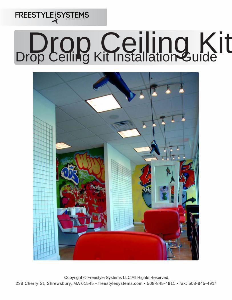
Step three: Installing Freestylist™ support system
Freestylesystems.com • Tel. 508.845.4911
Freestyle Systems
Remove 2 screws from each side of the cover (screw locations shown below). Place the Freestyl-ist onto the pan being careful to feed the Freelock™ connector through the flange hole first. The cord guide will fit into the flange; position it in the correct location after feeding the connector through. Reinstall the cover screws in the same holes they were removed from, as shown below. Plug the Freestylist's power cord into the outlet provided by your electrician (each unit should be on its own 15 amp 120V circuit). To adjust the apparent weight and the resting height the hair dryer, the Freestylist support system comes with a remote control and remote diode, or can be manually adjusted. Plug the remote diode into the Freestylist if equiped. The remote diode comes with its own installation instructions.
Cord GuideFreelock™ connector
Cover screws
Screw locations
FSS-DK
DROPCEILING
*Remote diodelocation*
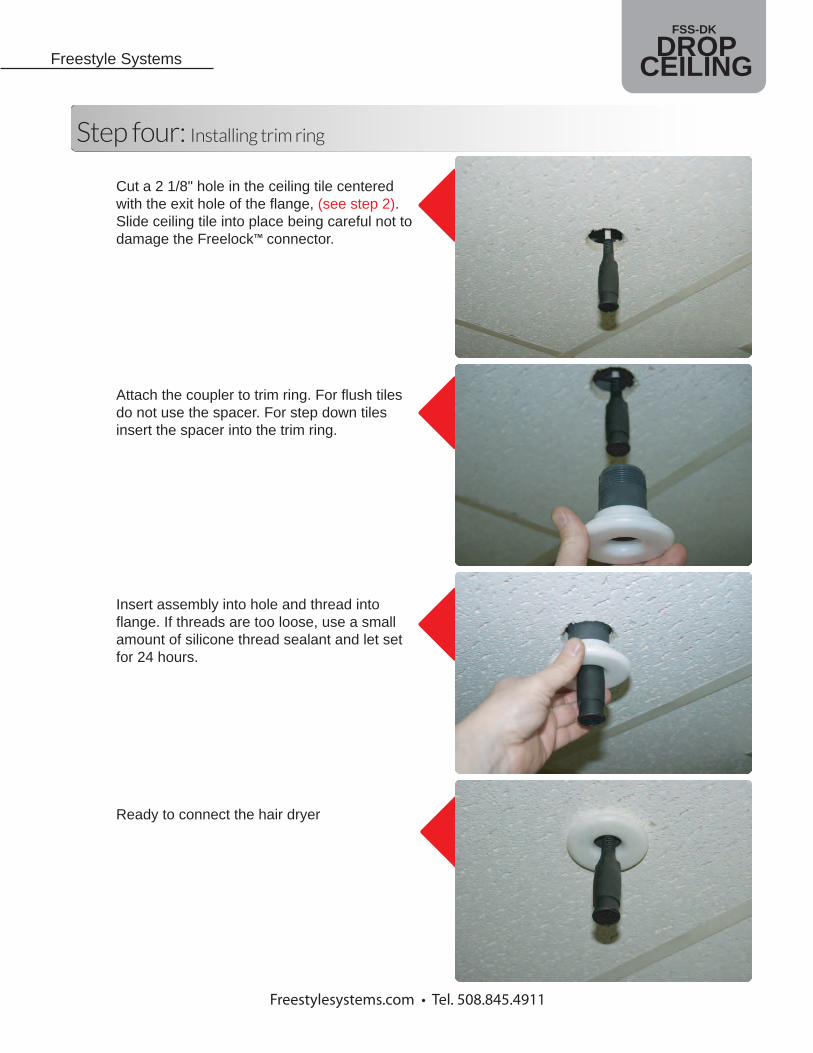
Step four: Installing trim ring
Freestylesystems.com • Tel. 508.845.4911
Freestyle Systems
Cut a 2 1/8" hole in the ceiling tile centeredwith the exit hole of the flange, (see step 2).Slide ceiling tile into place being careful not to damage the Freelock™ connector.
Attach the coupler to trim ring. For flush tiles do not use the spacer. For step down tiles insert the spacer into the trim ring.
Insert assembly into hole and thread into flange. If threads are too loose, use a small amount of silicone thread sealant and let set for 24 hours.
Ready to connect the hair dryer
FSS-DK
DROPCEILING
8-3/8"
6-7/8" 10-15/16"
7-7/
8"8-
1/2"
18"
16-3
/8"
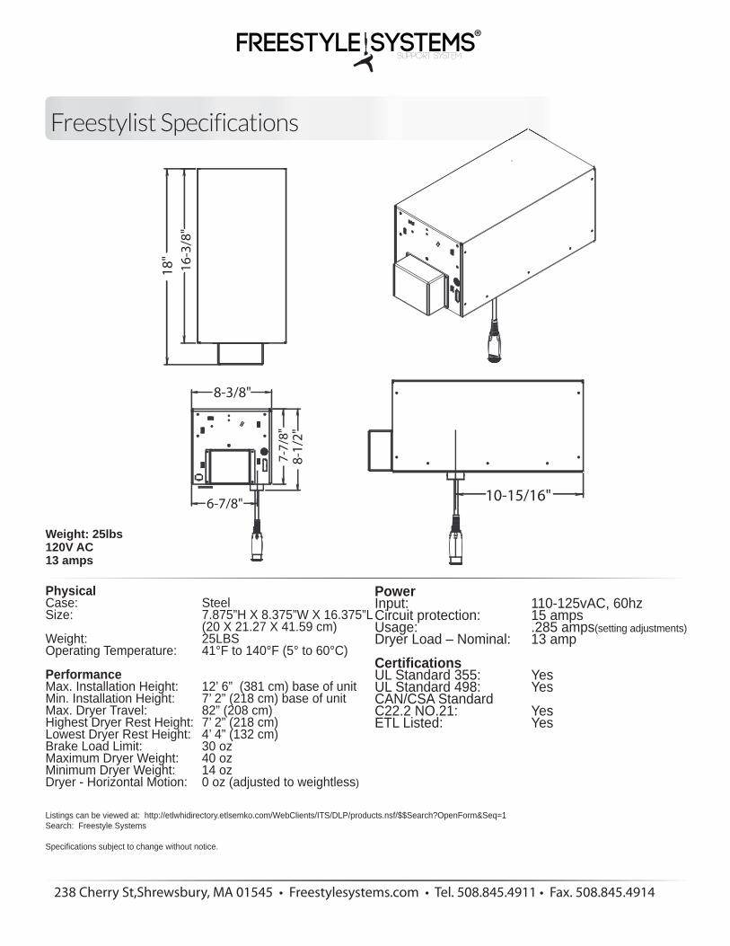
Weight: 25lbs120V AC13 amps
Freestylist Specifications
238 Cherry St,Shrewsbury, MA 01545 • Freestylesystems.com • Tel. 508.845.4911 • Fax. 508.845.4914
PhysicalCase: Steel Size: 7.875”H X 8.375”W X 16.375”L (20 X 21.27 X 41.59 cm) Weight: 25LBS Operating Temperature: 41°F to 140°F (5° to 60°C)
PerformanceMax. Installation Height: 12’ 6” (381 cm) base of unit Min. Installation Height: 7’ 2” (218 cm) base of unit Max. Dryer Travel: 82” (208 cm) Highest Dryer Rest Height: 7’ 2” (218 cm) Lowest Dryer Rest Height: 4’ 4” (132 cm) Brake Load Limit: 30 oz Maximum Dryer Weight: 40 oz Minimum Dryer Weight: 14 oz Dryer - Horizontal Motion: 0 oz (adjusted to weightless)
Listings can be viewed at: http://etlwhidirectory.etlsemko.com/WebClients/ITS/DLP/products.nsf/$$Search?OpenForm&Seq=1Search: Freestyle Systems
Specifications subject to change without notice.
PowerInput: 110-125vAC, 60hz Circuit protection: 15 amps Usage: .285 amps(setting adjustments)Dryer Load – Nominal: 13 amp
CertificationsUL Standard 355: Yes UL Standard 498: Yes CAN/CSA Standard C22.2 NO.21: Yes ETL Listed: Yes