DRIVE SHAFT – FRONT DRIVE SHAFT - Dynv12.dyndns.org/Toyota/Yaris/Drive Shaft.pdf · drive shaft...
16
DRIVE SHAFT – FRONT DRIVE SHAFT DS–1 DS DRIVE LINE DRIVE SHAFT FRONT DRIVE SHAFT COMPONENTS FRONT AXLE HUB NUT FRONT DRIVE SHAFT ASSEMBLY RH FRONT SPEED SENSOR FRONT STABILIZER LINK ASSEMBLY TIE ROD END SUB-ASSEMBLY FRONT DRIVE SHAFT HOLE SNAP RING N*m (kgf*cm, ft*lbf) : Specified torque Non-reusable part 29 (300, 22) 8.5 (87, 75 in.*lbf) 49 (500, 36) 216 (2,203, 160) 98 (1,000, 72) 74 (755, 55) 23 (235, 17) COTTER PIN w/o ABS: w/ ABS: CLIP FRONT FLEXIBLE HOSE FRONT AXLE ASSEMBLY AUTOMATIC TRANSMISSION CASE PROTECTOR FRONT LOWER SUSPENSION ARM FRONT DRIVE SHAFT ASSEMBLY LH C121811E02
Transcript of DRIVE SHAFT – FRONT DRIVE SHAFT - Dynv12.dyndns.org/Toyota/Yaris/Drive Shaft.pdf · drive shaft...

DRIVE SHAFT – FRONT DRIVE SHAFT DS–1
S
DDRIVE LINEDRIVE SHAFTFRONT DRIVE SHAFTCOMPONENTS
FRONT AXLE HUB NUT
FRONT DRIVE SHAFT
ASSEMBLY RH
FRONT SPEED SENSOR
FRONT STABILIZER
LINK ASSEMBLY
TIE ROD END
SUB-ASSEMBLY
FRONT DRIVE SHAFT
HOLE SNAP RING
N*m (kgf*cm, ft*lbf) : Specified torque Non-reusable part
29 (300, 22)
8.5 (87, 75 in.*lbf)
49 (500, 36)
216 (2,203, 160)
98 (1,000, 72)
74 (755, 55)
23 (235, 17)
COTTER PIN
w/o ABS:
w/ ABS:
CLIP
FRONT FLEXIBLE HOSE
FRONT AXLE
ASSEMBLY
AUTOMATIC TRANSMISSION
CASE PROTECTOR
FRONT LOWER SUSPENSION ARM
FRONT DRIVE SHAFT
ASSEMBLY LH
C121811E02

DS–2 DRIVE SHAFT – FRONT DRIVE SHAFT
DS
FRONT AXLE
INBOARD JOINT
BOOT
FRONT AXLE INBOARD
JOINT BOOT CLAMP
FRONT AXLE OUTBOARD
JOINT BOOT CLAMP
FRONT DRIVE INBOARD JOINT ASSEMBLY
FRONT DRIVE
SHAFT DAMPER
FRONT DRIVE
SHAFT DAMPER
CLAMP
FRONT DRIVE SHAFT DUST COVER
FRONT DRIVE SHAFT HOLE SNAP RING
Non-reusable part
for One-touch Clamp Type:
for Hook Clamp Type:
FRONT AXLE INBOARD
JOINT BOOT CLAMP
for One-touch Clamp Type:
FRONT AXLE OUTBOARD
JOINT SHAFT ASSEMBLY
for Hook Clamp Type:
TRIPOD JOINT ASSEMBLY
FRONT DRIVE INNER
SHAFT SNAP RING
for RH Side:
FRONT NO. 2 AXLE INBOARD
JOINT BOOT CLAMP
FRONT NO. 2 AXLE OUTBOARD
JOINT BOOT CLAMP
FRONT NO. 2 AXLE INBOARD
JOINT BOOT CLAMP
FRONT AXLE OUTBOARD JOINT BOOT
C116950E03
DRIVE SHAFT – FRONT DRIVE SHAFT DS–3
S
DREMOVAL1. DISCONNECT CABLE FROM NEGATIVE BATTERY
TERMINAL2. DRAIN AUTOMATIC TRANSAXLE FLUID (for
Automatic Transaxle) (See page AX-159)3. DRAIN TRANSAXLE OIL (for Manual Transaxle) (See
page MX-26)4. REMOVE FRONT WHEEL5. REMOVE FRONT AXLE HUB NUT
(a) Using SST and a hammer, release the staked part of the axle hub nut.SST 09930-00010NOTICE:• Insert SST into the groove with the flat
surface facing up.• Do not damage the tip of SST using grinders.• Completely unstake the staked part before
removing the axle hub nut.• Do not damage the threads of the drive shaft.
(b) Using a 30 mm socket wrench, remove the axle hub nut.
6. SEPARATE FRONT SPEED SENSOR (w/ ABS)(a) Remove the bolt and separate the speed sensor
and flexible hose.
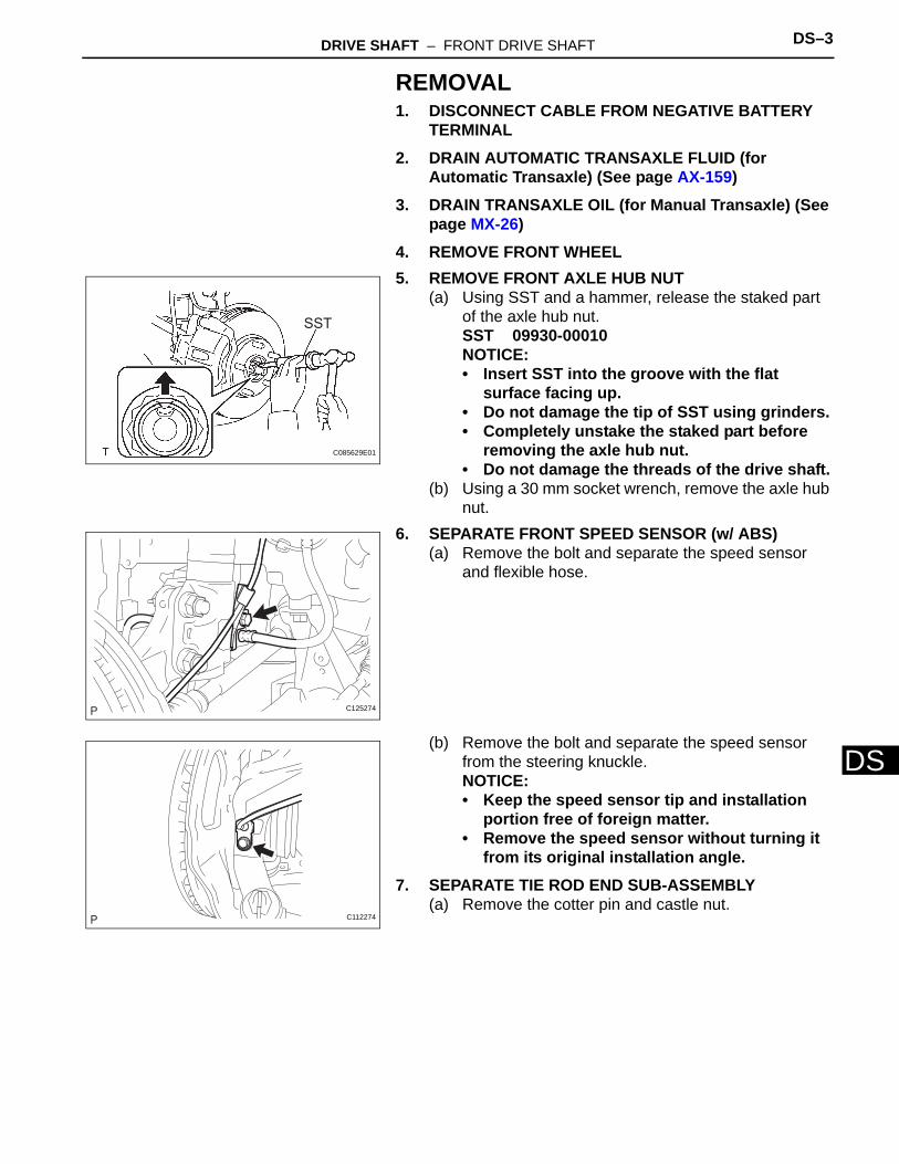
(b) Remove the bolt and separate the speed sensor from the steering knuckle.NOTICE:• Keep the speed sensor tip and installation
portion free of foreign matter.• Remove the speed sensor without turning it
from its original installation angle.7. SEPARATE TIE ROD END SUB-ASSEMBLY
(a) Remove the cotter pin and castle nut.
SST
C085629E01
C125274
C112274

DS–4 DRIVE SHAFT – FRONT DRIVE SHAFT
DS
(b) Using SST, separate the tie rod end from the steering knuckle.SST 09628-62011NOTICE:Do not damage the tie rod end dust cover.
8. SEPARATE FRONT STABILIZER LINK ASSEMBLY(a) Remove the nut and separate the stabilizer link from
the shock absorber.HINT:If the ball joint turns together with the nut, use a socket hexagon wrench 6 to hold the stud.
9. SEPARATE FRONT LOWER SUSPENSION ARM(a) Remove the clip and castle nut.
(b) Using SST, separate the lower arm.SST 09628-00011NOTICE:• Do not damage the lower ball joint dust cover.• Suspend SST with a piece of string or the
equivalent.10. SEPARATE FRONT AXLE ASSEMBLY
(a) Using a plastic hammer, tap the end of the drive shaft and disengage the fitting between the drive shaft and front axle.HINT:If it is difficult to disengage the fitting, tap the end of the drive shaft with a brass bar and hammer.
(b) Push the front axle out of the vehicle to remove the drive shaft from the front axle.NOTICE:• Do not push the front axle further out of the
vehicle than is necessary.• Do not damage the outboard joint boot.• Do not damage the speed sensor rotor.
SST
C116895E01
C106044
C107513
SSTC107514E01

DRIVE SHAFT – FRONT DRIVE SHAFT DS–5
S
D• Suspend the drive shaft with a piece of string or the equivalent.
11. REMOVE AUTOMATIC TRANSMISSION CASE PROTECTOR (w/o ABS)(a) Remove the 2 bolts and transmission case
protector.
12. REMOVE FRONT DRIVE SHAFT ASSEMBLY LH(a) Using SST, remove the drive shaft.
SST 09520-01010, 09520-24010 (09520-32040)NOTICE:• Do not damage the oil seal.• Do not damage the inboard joint boot.• Do not drop the drive shaft.
13. REMOVE FRONT DRIVE SHAFT ASSEMBLY RH(a) Using a screwdriver and hammer, remove the drive
shaft.NOTICE:• Do not damage the oil seal.• Do not damage the inboard joint boot.• Do not drop the drive shaft.
14. FIX FRONT AXLE ASSEMBLYSST 09608-16042 (09608-02021, 09608-02041)HINT:The hub bearing could be damaged if it is subjected to the vehicle's full weight, such as when moving the vehicle with the drive shaft removed. If it is absolutely necessary to place the vehicle's full weight on the hub bearing, first support it with SST.
C121812
C107924
C116896
SST
C112583E01

DS–6 DRIVE SHAFT – FRONT DRIVE SHAFT
DS
DISASSEMBLY1. REMOVE FRONT NO. 2 AXLE INBOARD JOINT
BOOT CLAMP(a) for One-touch Clamp Type:
(1) Using a screwdriver, release the staked part of the boot clamp and separate the boot clamp.
(b) for Hook Clamp Type:(1) Using needle-nose pliers, disengage the hook
and remove the boot clamp.
2. REMOVE FRONT AXLE INBOARD JOINT BOOT CLAMP(a) for One-touch Clamp Type:
(1) Using a screwdriver, release the staked part of the boot clamp and separate the boot clamp.
(b) for Hook Clamp Type:(1) Using needle-nose pliers, disengage the hook
and remove the boot clamp.
3. SEPARATE FRONT AXLE INBOARD JOINT BOOT(a) Separate the inboard joint boot from the inboard
joint.
4. REMOVE FRONT DRIVE INBOARD JOINT ASSEMBLY(a) Remove the old grease from the inboard joint.
(b) Place matchmarks on the inboard joint and outboard joint shaft.NOTICE:Do not cause any damage when placing the marks.
(c) Remove the inboard joint from the outboard joint shaft.
(d) Fix the outboard joint shaft in a vise between aluminum plates.NOTICE:Do not overtighten the vise.
C067083
F047432E01
C067084
F047433E01
Matchmarks
F047434E01

DRIVE SHAFT – FRONT DRIVE SHAFT DS–7
S
D(e) Using a snap ring expander, remove the snap ring.
(f) Place matchmarks on the tripod joint and outboard joint shaft.NOTICE:Do not cause any damage when placing the marks.
(g) Using a brass bar and hammer, remove the tripod joint.NOTICE:Do not tap the roller.
(h) Remove the inboard joint boot No. 2 clamp, the inboard joint boot and the inboard joint boot clamp.
5. REMOVE FRONT DRIVE SHAFT DAMPER CLAMP (for RH Side)(a) Using needle-nose pliers, disengage the hook and
remove the damper clamp.
6. REMOVE FRONT DRIVE SHAFT DAMPER (for RH Side)
7. REMOVE FRONT NO. 2 AXLE OUTBOARD JOINT BOOT CLAMP(a) Using a screwdriver, release the staked part of the
boot clamp and remove the boot clamp.
8. REMOVE FRONT AXLE OUTBOARD JOINT BOOT CLAMP(a) Using a screwdriver, release the staked part of the
boot clamp and remove the boot clamp.
9. REMOVE FRONT AXLE OUTBOARD JOINT BOOT(a) Remove the outboard joint boot from the outboard
joint shaft.(b) Remove the old grease from the outboard joint.
C112599
Matchmarks
F047435E01
C121813
C107963
C107964

DS–8 DRIVE SHAFT – FRONT DRIVE SHAFT
DS
10. REMOVE FRONT DRIVE SHAFT HOLE SNAP RING(a) Using a screwdriver, remove the snap ring.
11. REMOVE FRONT DRIVE SHAFT DUST COVER(a) Using SST and a press, remove the dust cover.
SST 09950-00020NOTICE:Do not drop the inboard joint.
REASSEMBLY1. INSTALL FRONT DRIVE SHAFT DUST COVER
(a) Using SST and a press, install a new dust cover into the inboard joint until it is flush with the end.SST 09527-10011NOTICE:• Install the dust cover in the correct
orientation.• Do not deform the dust cover.
2. INSTALL FRONT DRIVE SHAFT HOLE SNAP RING(a) Install a new snap ring.
3. INSTALL FRONT AXLE OUTBOARD JOINT BOOT(a) Wrap the spline of the outboard joint shaft with
protective tape.(b) Install new parts onto the outboard joint shaft in the
following order.
(c) Pack the outboard joint shaft joint portion and outboard joint boot with grease.Standard Quantity:
125 to 135 g (4.4 to 4.8 oz.)(d) Install the outboard joint boot onto the outboard joint
shaft groove.NOTICE:Keep the groove free of grease.
C057543
SST
F047437E01
SST
F047438E01
1. Front axle outboard joint boot No. 2 clamp
2. Front axle outboard joint boot
3. Front axle outboard joint boot clamp

DRIVE SHAFT – FRONT DRIVE SHAFT DS–9
S
D4. INSTALL FRONT NO. 2 AXLE OUTBOARD JOINT BOOT CLAMPCAUTION:Wear protective gloves to avoid injuries to your hands.(a) Install the boot clamp onto the outboard joint boot
and provisionally bend the lever.NOTICE:• Set the lever into the guide groove correctly.• Check the band and the lever for any
deformation before bending the lever.• Set the lever into the guide groove correctly
and install the clamp as far into the inner side of the vehicle as possible.
(b) Lean your weight on your hand and roll the outboard joint forward while pressing the outboard joint against the work plane. Roll the outboard joint and fold the lever until a click sound can be heard.NOTICE:• Do not damage the deflector.• Make sure that the outboard joint is in direct
contact with the work plane.
C107943
Contact
Weight
C112269E01

DS–10 DRIVE SHAFT – FRONT DRIVE SHAFT
DS
(c) Using a plastic hammer, tap the buckle to fix it while adjusting the clearance between the lever and the groove to make the clearances between the buckle edge and the lever end even.NOTICE:Do not damage the outboard joint boot.
5. INSTALL FRONT AXLE OUTBOARD JOINT BOOT CLAMPCAUTION:Wear protective gloves to avoid injuries to your hands.
(a) Install the boot clamp onto the outboard joint boot and provisionally bend the lever.NOTICE:• Set the lever into the guide groove correctly.• Check the band and the lever for any
deformation before bending the lever.
(b) Using water pump pliers, pinch the boot clamp to provisionally fix it.
C112270
C107948
Place the tip
near the center
of the lever
C112271E01

DRIVE SHAFT – FRONT DRIVE SHAFT DS–11
S
D(c) Using a plastic hammer, tap the buckle to fix it while adjusting the clearance between the lever and the groove to make the clearances between the buckle edge and the lever end even.NOTICE:Do not damage the outboard joint boot.
6. INSTALL FRONT DRIVE SHAFT DAMPER (for RH Side)(a) Install the drive shaft damper onto dimension (A)
shown in the illustration.Dimension (A):
425.6 to 429.6 mm (16.76 to 16.91 in.)
7. INSTALL FRONT DRIVE SHAFT DAMPER CLAMP (for RH Side)(a) Using needle-nose pliers, align the concave part
with the protrusion of a new damper clamp in order to fix it.
8. INSTALL FRONT DRIVE INBOARD JOINT ASSEMBLY(a) Install new parts onto the outboard joint shaft in the
following order.
(b) Fix the outboard joint shaft in a vise between aluminum plates.NOTICE:Do not overtighten the vise.
(c) Remove the protective tape.
C112272
Dimension (A)
C121814E01
C121813 1. Front axle inboard joint boot clamp
2. Front axle inboard joint boot
3. Front axle inboard joint boot No. 2 clamp

DS–12 DRIVE SHAFT – FRONT DRIVE SHAFT
DS
(d) Align the matchmarks and install the tripod joint onto the outboard joint shaft.NOTICE:Face the serration side of the tripod joint outward and install it onto the outboard joint end.
(e) Using a brass bar and hammer, install the tripod joint.NOTICE:• Do not hit the roller portion.• Keep the tripod joint free of foreign matter.
(f) Using a snap ring expander, install a new snap ring.(g) Pack the inboard joint with grease.
Standard Quantity:125 to 135 g (4.4 to 4.8 oz.)
(h) Align the matchmarks and install the inboard joint onto the outboard joint shaft.
9. INSTALL FRONT AXLE INBOARD JOINT BOOT(a) Install the inboard joint boot into the grooves of the
inboard joint and outboard joint shaft.NOTICE:Keep the grooves free of grease.
10. INSTALL FRONT NO. 2 AXLE INBOARD JOINT BOOT CLAMP(a) for One-touch Clamp Type:
(1) Install the boot clamp onto the inboard joint boot and caulk the boot clamp with a screwdriver.NOTICE:Do not damage the boot.
(b) for Hook Clamp Type:(1) Using needle-nose pliers, align the concave
part with the protrusion of the boot clamp in order to fix it.NOTICE:• Do not damage the boot.• Do not deform the claw of the hook.
MatchmarksF047445E01
C112599
Matchmarks
F047434E01
C081794
F047432E01

DRIVE SHAFT – FRONT DRIVE SHAFT DS–13
S
D11. INSTALL FRONT AXLE INBOARD JOINT BOOT CLAMP(a) for One-touch Clamp Type:
(1) Install the boot clamp onto the inboard joint boot and caulk the boot clamp with a screwdriver.NOTICE:Do not damage the boot.
(b) for Hook Clamp Type:(1) Using needle-nose pliers, align the concave
part with the protrusion of the boot clamp in order to fix it.NOTICE:• Do not damage the boot.• Do not deform the claw of the hook.
12. INSPECT FRONT DRIVE SHAFT(a) Check whether the drive shaft dimensions are within
the following specifications.HINT:The following table shows dimension (A) of the drive shaft.Dimension (A)
(b) Check for noticeable looseness when turning the joint up and down, left and right, and in the thrust direction.
(c) Check for cracks, damage and grease leakage on the boot joint.NOTICE:Keep the drive shaft level while moving it.
C081795
F047433E01
Dimension (A)
C107965E01
LH RH
584.3 mm(23.00 in.)
826.3 mm(32.53 in.)
C110169

DS–14 DRIVE SHAFT – FRONT DRIVE SHAFT
DS
INSTALLATION1. INSTALL FRONT DRIVE SHAFT ASSEMBLY LH
(a) for Automatic Transaxle:(1) Coat the spline of the inboard joint with ATF.
(b) for Manual Transaxle:(1) Coat the spline of the inboard joint with gear oil.
(c) Align the inboard joint splines and install the drive shaft with a screwdriver and hammer.NOTICE:• Face the cut area of the front drive inboard
joint hole snap ring downward.• Do not damage the oil seal.• Do not damage the inboard joint boot.HINT:Confirm whether the drive shaft is securely driven in by checking the reaction force and sound.
2. INSTALL FRONT DRIVE SHAFT ASSEMBLY RHHINT:The installation procedure for the RH side is the same as that for the LH side.
3. INSTALL AUTOMATIC TRANSMISSION CASE PROTECTOR (w/o ABS)(a) Install the transmission case protector with the 2
bolt.Torque: 23 N*m (235 kgf*cm, 17 ft.*lbf)
4. INSTALL FRONT AXLE ASSEMBLY(a) Push the front axle out of the vehicle to align the
spline of the drive shaft with the front axle and insert the front axle.NOTICE:• Do not push the front axle further out of the
vehicle than is necessary.• Do not damage the outboard joint boot.• Check for any foreign matter on the speed
sensor rotor and insertion part.• Do not damage the speed sensor rotor.
5. INSTALL FRONT LOWER SUSPENSION ARM(a) Install the lower arm onto the steering knuckle with
a new castle nut.Torque: 98 N*m (1,000 kgf*cm, 72 ft.*lbf)NOTICE:If the holes for the clip are not aligned, tighten the nut by a further turn of up to 60°.
(b) Install a new clip.
C116899
C121812
C107513

DRIVE SHAFT – FRONT DRIVE SHAFT DS–15
S
D6. INSTALL FRONT STABILIZER LINK ASSEMBLY(a) Install the stabilizer link with the nut.
Torque: 74 N*m (755 kgf*cm, 55 ft.*lbf)HINT:If the ball joint turns together with the nut, use a socket hexagon wrench 6 to hold the stud.
7. INSTALL TIE ROD END SUB-ASSEMBLY(a) Install the tie rod end onto the steering knuckle with
a new castle nut.Torque: 49 N*m (500 kgf*cm, 36 ft.*lbf)NOTICE:If the holes for the clip are not aligned, tighten the nut by a further turn of up to 60°.
(b) Install a new cotter pin.
8. INSTALL FRONT SPEED SENSOR (w/ ABS)(a) Install the speed sensor onto the steering knuckle
with the bolt.Torque: 8.5 N*m (87 kgf*cm, 75 in.*lbf)NOTICE:• Check that the speed sensor tip and
installation portion are free of foreign matter.• Install the speed sensor without turning it
from its original installation angle.
(b) Install the flexible hose and speed sensor with the bolt.Torque: 29 N*m (300 kgf*cm, 22 ft.*lbf)NOTICE:Install the flexible hose and speed sensor without twisting them.
9. INSTALL FRONT AXLE HUB NUT(a) Using a 30 mm socket wrench, install a new axle
hub nut.Torque: 216 N*m (2,203 kgf*cm, 160 ft.*lbf)
(b) Using a chisel and hammer, caulk the axle hub nut.
10. INSTALL FRONT WHEELTorque: 103 N*m (1,050 kgf*cm, 76 ft.*lbf)
11. CONNECT CABLE TO NEGATIVE BATTERY TERMINALTorque: 5.4 N*m (55 kgf*cm, 48 in.*lbf)
C106044
C107961
C112274
C125274
C057566

DS–16 DRIVE SHAFT – FRONT DRIVE SHAFT
DS
12. ADD AUTOMATIC TRANSAXLE FLUID (for Automatic Transaxle) (See page AX-170)
13. ADD TRANSAXLE OIL (for Manual Transaxle)14. INSPECT AUTOMATIC TRANSAXLE FLUID (for
Automatic Transaxle) (See page AX-93)15. INSPECT TRANSAXLE OIL (for Manual Transaxle)
(See page MX-2)16. CHECK AUTOMATIC TRANSAXLE FLUID LEAKAGE
(for Automatic Transaxle)17. CHECK TRANSAXLE OIL LEAKAGE (for Manual
Transaxle)18. INSPECT AND ADJUST FRONT WHEEL ALIGNMENT
(See page SP-2)
19. CHECK ABS SENSOR SIGNAL (w/ ABS)(See page BC-14)