DRIVE SHAFT / PROPELLER SHAFT – FRONT DRIVE SHAFT …tijil.org/Manuals/xB Repair Manuals/04 xB...
12
300JO–01 SST SST C57565 F45378 F45379 F45754 LH: RH: C57827 30–6 – DRIVE SHAFT / PROPELLER SHAFT FRONT DRIVE SHAFT 1176 AuthorĂ: DateĂ: 2004 SCION xB REPAIR MANUAL (RM1031U) OVERHAUL HINT: Overhaul the RH following the same procedures as for the LH. 1. DRAIN MANUAL TRANSAXLE OIL (M/T TRANSAXLE) Torque: 39 N⋅m (398 kgf⋅cm, 29 ft⋅lbf) 2. DRAIN AUTOMATIC TRANSAXLE FLUID (A/T TRANSAXLE) Torque: 25 N⋅m (255 kgf⋅cm, 18 ft⋅lbf) 3. REMOVE FRONT WHEEL 4. REMOVE ENGINE UNDER COVER LH 5. REMOVE FRONT AXLE HUB LH NUT (a) Using SST and a hammer, pry up the retaining tab of the hub LH nut. SST 09930–00010 NOTICE: Loosen the staked part of the nut completely, otherwise the screw of the drive shaft may be damaged. (b) While applying the brakes, remove the hub LH nut. 6. SEPARATE SPEED SENSOR FRONT LH (a) Remove the bolt and the clip, and separate the speed sensor front LH and the flexible hose from the shock ab- sorber assy front LH. HINT: The positions of the bolt and clip on the right side differ from those on the left side. (b) Remove the bolt, and separate the speed sensor front LH from the steering knuckle. NOTICE: S Be careful not to damage the speed sensor. S Prevent foreign matter from adhering to the speed sensor.
Transcript of DRIVE SHAFT / PROPELLER SHAFT – FRONT DRIVE SHAFT …tijil.org/Manuals/xB Repair Manuals/04 xB...

300JO–01
SSTSSTC57565
F45378
F45379F45754
LH:
RH:
C57827
30–6–DRIVE SHAFT / PROPELLER SHAFT FRONT DRIVE SHAFT
1176Author�: Date�:
2004 SCION xB REPAIR MANUAL (RM1031U)
OVERHAULHINT:Overhaul the RH following the same procedures as for the LH.1. DRAIN MANUAL TRANSAXLE OIL (M/T TRANSAXLE)
Torque: 39 N ⋅m (398 kgf ⋅cm, 29 ft ⋅lbf)2. DRAIN AUTOMATIC TRANSAXLE FLUID (A/T TRANSAXLE)
Torque: 25 N ⋅m (255 kgf ⋅cm, 18 ft ⋅lbf)3. REMOVE FRONT WHEEL4. REMOVE ENGINE UNDER COVER LH
5. REMOVE FRONT AXLE HUB LH NUT(a) Using SST and a hammer, pry up the retaining tab of the
hub LH nut.SST 09930–00010
NOTICE:Loosen the staked part of the nut completely, otherwise thescrew of the drive shaft may be damaged.(b) While applying the brakes, remove the hub LH nut.
6. SEPARATE SPEED SENSOR FRONT LH(a) Remove the bolt and the clip, and separate the speed
sensor front LH and the flexible hose from the shock ab-sorber assy front LH.
HINT:The positions of the bolt and clip on the right side differ fromthose on the left side.
(b) Remove the bolt, and separate the speed sensor front LHfrom the steering knuckle.
NOTICE:� Be careful not to damage the speed sensor.� Prevent foreign matter from adhering to the speed
sensor.

C58069C58069 D28934
F08765F08765 G22968
SST
D30290
SST
C63075C63075 D28937SST
SST
–DRIVE SHAFT / PROPELLER SHAFT FRONT DRIVE SHAFT30–7
1177Author�: Date�:
2004 SCION xB REPAIR MANUAL (RM1031U)
7. SEPARATE STABILIZER BAR FRONT(a) Hold the bolt with the spanner (10 mm) and remove the
nut.(b) Remove the 2 cushion retainers No.1, the 2 cushions and
separate the stabilizer bar front.
8. SEPARATE FRONT SUSPENSION ARM SUB–ASSYLOWER NO.1 LH
(a) Remove the clip and the nut.(b) Using SST, separate the front suspension arm sub–assy
lower No.1 LH from the steering knuckle.SST 09628–00011
9. SEPARATE TIE ROD END SUB–ASSY LH(a) Remove the cotter pin and the nut.(b) Using SST, separate the tie rod end sub–assy LH from the
steering knuckle.SST 09628–62011
10. SEPARATE FRONT AXLE ASSY LH(a) Using a plastic hammer, separate the front drive shaft assy LH from the front axle assy LH.NOTICE:� Be careful not to damage the boot.� Be careful not to damage the speed sensor rotor.
11. REMOVE FRONT DRIVE SHAFT ASSY LH(a) Using SST, remove the front drive shaft assy LH.
SST 09520–01010, 09520–24010 (09520–32040)NOTICE:� Be careful not to damage the oil seal and the boot.� Be careful not to drop the drive shaft assy.

C63066
C66796C66796 D28938
SST
N00191
C62539 C63307C62539 C63307 D30655
One Touch Clamp Type:
Claw Engagement Type:
30–8–DRIVE SHAFT / PROPELLER SHAFT FRONT DRIVE SHAFT
1178Author�: Date�:
2004 SCION xB REPAIR MANUAL (RM1031U)
12. REMOVE FRONT DRIVE SHAFT ASSY RH (RH DRIVESHAFT)
(a) Using a brass bar and a hammer, remove the front driveshaft assy RH.
NOTICE:� Be careful not to damage the oil seal and the boot.� Be careful not to drop the drive shaft assy.
13. FIX FRONT AXLE ASSY LHNOTICE:The hub bearing could be damaged if it is subjected to thevehicle’s wei ght, such as when moving the vehicle with thedrive shaft removed.Therefore, if it is ne cessary to place the vehicle’s weight onthe hub bearing, first support it with SST.
SST 09608–16042 (09608–02021, 09608–02041)
14. INSPECT FRONT DRIVE SHAFT ASSY LHNOTICE:Keep the drive shaft assy level during inspection.(a) Check that there is no remarkable play in the radial direc-
tion of the outboard joint.(b) Check if the inboard joint slides smoothly in the thrust
direction.(c) Check that there is no remarkable play in the radial direc-
tion of the inboard joint.(d) Check the boots for damage.15. REMOVE FRONT AXLE INBOARD JOINT BOOT LH
NO.2 CLAMP(a) One Touch Clamp Type:
Using a screwdriver, unclamp the inboard joint boot LHNo.2 clamp as shown in the illustration.
(b) Claw Engagement Type:Using needle nose pliers, remove the inboard joint bootLH No.2 clamp as shown in the illustration.

C63306C63290 C63306C63290 D30656
One Touch Clamp Type:
Claw Engagement Type:
F40222
Matchmarks
C63291C63291 D28939
–DRIVE SHAFT / PROPELLER SHAFT FRONT DRIVE SHAFT30–9
1179Author�: Date�:
2004 SCION xB REPAIR MANUAL (RM1031U)
16. REMOVE FRONT AXLE INBOARD JOINT BOOT LHCLAMP
(a) One Touch Clamp Type:Using a screwdriver, unclamp the inboard joint boot LHclamp as shown in the illustration.
(b) Claw Engagement Type:Using needle nose pliers, remove the inboard joint bootLH clamp as shown in the illustration.
17. SEPARATE FR AXLE INBOARD JOINT BOOT(a) Separate the inboard joint boot from the inboard joint assy LH.
18. REMOVE FRONT DRIVE INBOARD JOINT ASSY LH(a) Remove the old grease from the inboard joint assy LH.(b) Put matchmarks on the inboard joint assy LH and out-
board joint shaft assy.NOTICE:Do not use a punch for marking.(c) Remove the inboard joint assy LH from the outboard joint
shaft assy.
(d) Using a snap ring expander, remove the inner LH shaftsnap ring.

F40224
Matchmarks Brass Bar
D30598
One Touch Clamp Type:
Claw Engagement Type:
C63445
30–10–DRIVE SHAFT / PROPELLER SHAFT FRONT DRIVE SHAFT
1180Author�: Date�:
2004 SCION xB REPAIR MANUAL (RM1031U)
(e) Put matchmarks on the outboard joint shaft assy and thetripod joint assy.
NOTICE:Do not use a punch for marking.(f) Using a brass bar and a hammer, remove the tripod joint
assy from the outboard joint shaft assy.NOTICE:Do not tap the roller.(g) Remove the inboard joint boot LH No.2 clamp, the in-
board joint boot and the inboard joint boot LH clamp.19. REMOVE DRIVE SHAFT DAMPER SETTING CLAMP
(RH DRIVE SHAFT)HINT:Use the following procedure for RH disassembly only.(a) One Touch Clamp Type:
Using a screwdriver, unclamp the damper setting clampas shown in the illustration.
(b) Claw Engagement Type:Using needle nose pliers, remove the damper settingclamp as shown in the illustration.
20. REMOVE DRIVE SHAFT DAMPER (RH DRIVE SHAFT)HINT:Use the following procedure for RH disassembly only.(a) Remove the drive shaft damper RH.
21. REMOVE FRONT AXLE OUTBOARD JOINT BOOT LHNO.2 CLAMP
(a) Using a screwdriver, unclamp the outboard joint boot LHNo.2 clamp.

C63444
C57543
G23850
SST
G23851
SST
–DRIVE SHAFT / PROPELLER SHAFT FRONT DRIVE SHAFT30–11
1181Author�: Date�:
2004 SCION xB REPAIR MANUAL (RM1031U)
22. REMOVE FRONT AXLE OUTBOARD JOINT BOOT LHCLAMP
(a) Using a screwdriver, unclamp the outboard joint boot LHclamp.
23. REMOVE FRONT AXLE OUTBOARD JOINT BOOT(a) Remove the outboard joint boot from the outboard joint shaft assy.(b) Remove the old grease from the outboard joint.
24. REMOVE FRONT DRIVE SHAFT LH HOLE SNAP RING(a) Using a screwdriver, remove the LH hole snap ring.
25. REMOVE FRONT DRIVE SHAFT DUST COVER LH(a) Using SST and a press, remove the dust cover LH.
SST 09950–00020NOTICE:Be careful not to drop the inboard joint assy.
26. INSTALL FRONT DRIVE SHAFT DUST COVER LH(a) Using SST and a press, install the dust cover LH.
SST 09527–10011NOTICE:� Be careful not to damage the dust cover.� Dust cover should be installed completely.
27. INSTALL FRONT DRIVE SHAFT LH HOLE SNAP RING(a) Install a new LH hole snap ring.
F40235
Turn
Hold
SST
F40236
SST
F40237
Turn
Hold
SST
30–12–DRIVE SHAFT / PROPELLER SHAFT FRONT DRIVE SHAFT
1182Author�: Date�:
2004 SCION xB REPAIR MANUAL (RM1031U)
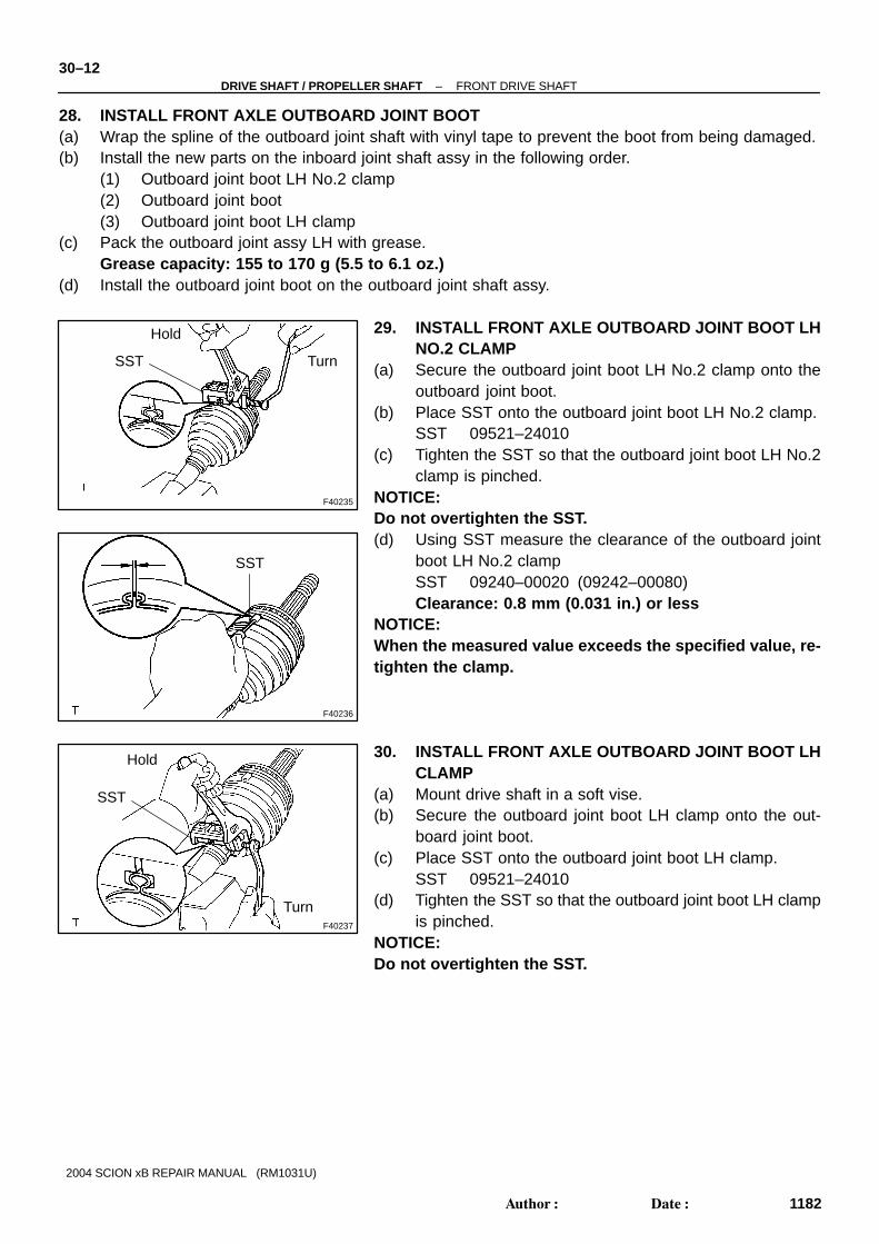
28. INSTALL FRONT AXLE OUTBOARD JOINT BOOT(a) Wrap the spline of the outboard joint shaft with vinyl tape to prevent the boot from being damaged.(b) Install the new parts on the inboard joint shaft assy in the following order.
(1) Outboard joint boot LH No.2 clamp(2) Outboard joint boot(3) Outboard joint boot LH clamp
(c) Pack the outboard joint assy LH with grease.Grease capacity: 155 to 170 g (5.5 to 6.1 oz.)
(d) Install the outboard joint boot on the outboard joint shaft assy.
29. INSTALL FRONT AXLE OUTBOARD JOINT BOOT LHNO.2 CLAMP
(a) Secure the outboard joint boot LH No.2 clamp onto theoutboard joint boot.
(b) Place SST onto the outboard joint boot LH No.2 clamp.SST 09521–24010
(c) Tighten the SST so that the outboard joint boot LH No.2clamp is pinched.
NOTICE:Do not overtighten the SST.(d) Using SST measure the clearance of the outboard joint
boot LH No.2 clampSST 09240–00020 (09242–00080)Clearance: 0.8 mm (0.031 in.) or less
NOTICE:When the measured value exceeds the specified value, re-tighten the clamp.
30. INSTALL FRONT AXLE OUTBOARD JOINT BOOT LHCLAMP
(a) Mount drive shaft in a soft vise.(b) Secure the outboard joint boot LH clamp onto the out-
board joint boot.(c) Place SST onto the outboard joint boot LH clamp.
SST 09521–24010(d) Tighten the SST so that the outboard joint boot LH clamp
is pinched.NOTICE:Do not overtighten the SST.

F40238
SST
D30599
One Touch Clamp Type:
Claw Engagement Type:
–DRIVE SHAFT / PROPELLER SHAFT FRONT DRIVE SHAFT30–13
1183Author�: Date�:
2004 SCION xB REPAIR MANUAL (RM1031U)
(e) Using SST measure the clearance of the outboard jointboot LH clamp.SST 09240–00020 (09242–00080)Clearance: 0.8 mm (0.031 in.) or less
NOTICE:When the measured value exceeds the specified value, re-tighten the clamp.
31. INSTALL DRIVE SHAFT DAMPER (RH DRIVE SHAFT)HINT:Use the following procedure for RH disassembly only.(a) Install the drive shaft damper RH on the outboard joint shaft assy.
32. INSTALL DRIVE SHAFT DAMPER SETTING CLAMP(RH DRIVE SHAFT)
HINT:Use the following procedure for RH disassembly only.(a) Install the damper setting clamp to the shaft.NOTICE:Be sure to install the clamp in the correct position.
(b) One Touch Clamp Type:Using a screwdriver, install the damper setting clamp asshown in the illustration.
(c) Claw Engagement Type:Using needle nose pliers, install the damper setting clampas shown in the illustration.
33. INSTALL FRONT DRIVE INBOARD JOINT ASSY LHHINT:Before installing the boot, wrap the spline of the drive shaft withvinyl tape to prevent the boot from damaged.(a) Install the new parts on the outboard joint shaft assy in the
following order.(1) Inboard joint boot LH clamp(2) Inboard joint boot(3) Inboard joint boot LH No.2 clamp

F40227
Matchmarks
C63291C63291 D28939
F40222
Matchmarks
30–14–DRIVE SHAFT / PROPELLER SHAFT FRONT DRIVE SHAFT
1184Author�: Date�:
2004 SCION xB REPAIR MANUAL (RM1031U)
(b) Align the matchmarks, install the tripod joint assy to theoutboard joint assy.
(c) Using a brass bar and a hammer, install the tripod jointassy.
NOTICE:� Do not tap the roller.� Be sure to install the tripod joint in the correct direc-
tion.
(d) Using a snap ring expander, install a new inner LH shaftsnap ring.
(e) Apply grease to the inboard joint assy LH.Grease capacity: 125 to 135 g (4.5 to 4.8 oz.)
(f) Align the matchmarks, install the inboard joint assy LH onthe outboard joint shaft assy.
34. INSTALL FR AXLE INBOARD JOINT BOOT(a) Install the inboard joint boot on the inboard joint assy and the outboard joint shaft assy.

D30658
One Touch Clamp Type:
Claw Engagement Type:
D30657
One Touch Clamp Type:
Claw Engagement Type:
N00191
–DRIVE SHAFT / PROPELLER SHAFT FRONT DRIVE SHAFT30–15
1185Author�: Date�:
2004 SCION xB REPAIR MANUAL (RM1031U)
35. INSTALL FRONT AXLE INBOARD JOINT BOOT LHNO.2 CLAMP
(a) One Touch Clamp Type:Using screwdriver, install the inboard joint boot LH No.2clamp as shown in the illustration.
(b) Claw Engagement Type:Using needle nose pliers, install the inboard joint boot LHNo.2 clamp as shown in the illustration.
36. INSTALL FRONT AXLE INBOARD JOINT BOOT LHCLAMP
(a) One Touch Clamp Type:Using screwdriver, install the inboard joint boot LH clampas shown in the illustration.
(b) Claw Engagement Type:Using needle nose pliers, install the inboard joint boot LHclamp as shown in the illustration.
37. INSPECT FRONT DRIVE SHAFTNOTICE:Keep the drive shaft assy level during inspection.(a) Check that there is no remarkable play in the outboard
joint.(b) Check if the inboard joint slides smoothly in the thrust
direction.(c) Check that there is no remarkable play in the radial direc-
tion of the inboard joint.(d) Check the boots for damage.

C63067
D27679
30–16–DRIVE SHAFT / PROPELLER SHAFT FRONT DRIVE SHAFT
1186Author�: Date�:
2004 SCION xB REPAIR MANUAL (RM1031U)
38. INSTALL FRONT DRIVE SHAFT ASSY LH(a) M/T:
Coat the spline of the inboard joint shaft assy with gear oil.(b) A/T:
Coat the spline of the inboard joint shaft assy with ATF.(c) Align the shaft splines, install the drive shaft assy LH with
a brass bar and a hammer.NOTICE:� Set the hole snap ring with the opening side facing
down.� Be careful not to damage the boot and the oil seal.
HINT:Whether the inboard joint shaft is in contact with the pinion shaftor not can be known from the sound or feeling when driving itin.
39. INSTALL FRONT DRIVE SHAFT ASSY RH (RH DRIVE SHAFT)HINT:Apply the same procedure to the RH.NOTICE:� Set the hole snap ring with the opening side facing down.� Be careful not to damage the boot and the oil seal.
40. INSTALL FRONT AXLE ASSY LH(a) Install the drive shaft assy LH to the front axle assy LH.NOTICE:� Be careful not to damage the outboard joint boot.� Be careful not to damage the speed sensor rotor.� Do not excessively push the front axle assy LH.
41. INSTALL TIE ROD END SUB–ASSY LH(a) Install the tie rod end sub–assy LH to the steering knuckle with the nut.
Torque: 49 N ⋅m (500 kgf ⋅cm, 36 ft ⋅lbf)(b) Install a new cotter pin.NOTICE:If the holes for the cotter pin are not aligned, tighten the nut up to 60 �.42. INSTALL FRONT SUSPENSION ARM SUB–ASSY LOWER NO.1 LH(a) Install the tie front suspension arm sub–assy lower No.1 LH to the steering knuckle with the nut.
Torque: 98 N ⋅m (1,000 kgf ⋅cm, 72 ft ⋅lbf)(b) Install a new clip.NOTICE:If the holes for the clip are not aligned, tighten the nut up to 60 �.
43. INSTALL STABILIZER BAR FRONT(a) Install the stabilizer bar front with 2 cushion retainers
No.1, 2 cushions and the nut, as shown in the illustration.NOTICE:Be sure to install the cushion and retainer in the correctdirection.(b) Torque the nut with the spanner (10mm).
Torque: 18 N ⋅m (184 kgf ⋅cm, 13 ft ⋅lbf)

F45378
F45379F45754
LH:
RH:
C57827
C57566
–DRIVE SHAFT / PROPELLER SHAFT FRONT DRIVE SHAFT30–17
1187Author�: Date�:
2004 SCION xB REPAIR MANUAL (RM1031U)
44. INSTALL SPEED SENSOR FRONT LH(a) Install the speed sensor front LH and the flexible hose on
the shock absorber assy front LH with the bolt and clip.Torque: 29 N ⋅m (300 kgf ⋅cm, 22 ft ⋅lbf)
HINT:The positions of the bolt and clip on the right side differ fromthose of the left side.
(b) Install the speed sensor front LH on the steering knucklewith the bolt.Torque: 8.0 N ⋅m (82 kgf ⋅cm, 71 in. ⋅lbf)
NOTICE:� Be careful not to damage the speed sensor.� Keep the speed sensor clean.� Do not twist the sensor wire when installing the speed
sensor.
45. INSTALL FRONT AXLE HUB LH NUT(a) Install a new hub LH nut.
Torque: 216 N ⋅m (2,200 kgf ⋅cm, 159 ft ⋅lbf)(b) Using a chisel and a hammer, stake the hub LH nut.
46. INSTALL ENGINE UNDER COVER LH47. INSTALL FRONT WHEEL
Torque: 103 N ⋅m (1,050 kgf ⋅cm, 76 ft ⋅lbf)48. ADD MANUAL TRANSAXLE OIL (M/T TRANSAXLE)49. INSPECT AND ADJUST MANUAL TRANSAXLE OIL (M/T TRANSAXLE) (See page 41–2)50. ADD AUTOMATIC TRANSAXLE FLUID (A/T TRANSAXLE)51. INSPECT AND ADJUST AUTOMATIC TRANSAXLE FLUID (A/T TRANSAXLE) (See page 40–2)52. INSPECT AND ADJUST FRONT WHEEL ALIGNMENT (See page 26–7)53. CHECK ABS SPEED SENSOR SIGNAL (See page 05–269)


![A Dimensions: [mm] B Recommended land pattern: [mm] D ...2012-12-06 2012-10-24 2012-08-08 2012-06-28 2012-03-12 DATE SSt SSt SSt SSt SSt SSt BY SSt SSt BD BD SSt DDe CHECKED Würth](https://static.fdocuments.in/doc/165x107/60f984e176666848374d15c0/a-dimensions-mm-b-recommended-land-pattern-mm-d-2012-12-06-2012-10-24.jpg)