Drive procedure
27
Drive Test Procedure Part I Steps followed to perform Drive Test •Physical Verification •Alarm Checking •Frequency Plan Verification •Hardware Configuration Verification Physical Verification Physical Verification is carried out by verifying physical parameter of the New Site with the TSSR (Technical Site Survey Report) such as Address, Lat, Long, Building Height, Antenna Height, Antenna Type, Orientation, Tilt(electrical & mechanical). Alarm Verification Alarms are generated mainly due to number of reasons, and these needs to checked before Drive is being carried out for the Site. Alarms are checked from the NOC (Network Operating Centre) and if found needs to be verified before drive being carried out. Frequency Plan Verification Frequency Plan can be verified from the NOC (Network Operating Centre) for BCCH and TCH frequencies being implemented as per the Site Integration Sheet sent to NOC (Network Operating Centre). Hardware Configuration Verification Hardware verification is performed to know the Site type, BTS Type, TRX Configuration, VSWR checking , Power measurement for each TRX. Following is the procedure and parameters that need to checked while performing Drive Test for a New Site. •CPC (Cell Parameter Check) •MOC (Mobile Originated Calls)
-
Upload
anil-parmar -
Category
Technology
-
view
2.140 -
download
4
description
a procedure to test coverage or network and trace fault in GSM system. to check signal quality and level we do drive test and basis of there data we analyse network problem and resolve it.
Transcript of Drive procedure

Drive Test Procedure Part I
Steps followed to perform Drive Test
•Physical Verification
•Alarm Checking
•Frequency Plan Verification
•Hardware Configuration Verification
Physical Verification Physical Verification is carried out by verifying physical parameter of the New Site with the TSSR (Technical Site Survey Report) such as Address, Lat, Long, Building Height, Antenna Height, Antenna Type, Orientation, Tilt(electrical & mechanical).
Alarm Verification Alarms are generated mainly due to number of reasons, and these needs to checked before Drive is being carried out for the Site. Alarms are checked from the NOC (Network Operating Centre) and if found needs to be verified before drive being carried out.
Frequency Plan Verification Frequency Plan can be verified from the NOC (Network Operating Centre) for BCCH and TCH frequencies being implemented as per the Site Integration Sheet sent to NOC (Network Operating Centre).
Hardware Configuration Verification Hardware verification is performed to know the Site type, BTS Type, TRX Configuration, VSWR checking , Power measurement for each TRX.
Following is the procedure and parameters that need to checked while performing Drive Test for a New Site.
•CPC (Cell Parameter Check)
•MOC (Mobile Originated Calls)
•MTC (Mobile Terminated Calls – Prepaid to Postpaid)
•SMS (Short Messaging Service)
•GPRS
•Intra Site Handover
•Inter Site Handover
•TRX Test
•Idle Drive (Normal Drive & Frequency Lock Drive)
•Dedicated Drive
Drive Test Procedure Part II
CPC (Cell Parameter Check)Given are the parameters that need to be checked while performing CPC.CGI (Cell Global Identity) consists if MCC+NCC+LAC+CIBCCH FrequencyBSICGSM Band
Definitions:
Time: It is system time of computer.
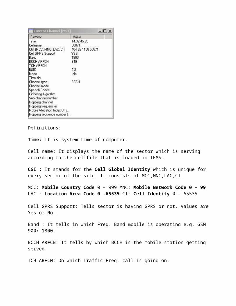
Cell name: It displays the name of the sector which is serving according to the cellfile that is loaded in TEMS.
CGI : It stands for the Cell Global Identity which is unique for every sector of the site. It consists of MCC,MNC,LAC,CI.
MCC: Mobile Country Code 0 – 999 MNC: Mobile Network Code 0 – 99 LAC : Location Area Code 0 -65535 CI: Cell Identity 0 – 65535
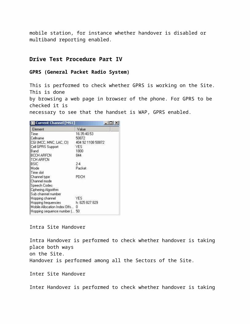
Cell GPRS Support: Tells sector is having GPRS or not. Values are Yes or No .
Band : It tells in which Freq. Band mobile is operating e.g. GSM 900/ 1800.
BCCH ARFCN: It tells by which BCCH is the mobile station getting served.
TCH ARFCN: On which Traffic Freq. call is going on.
BSIC (Base Station Identity Code) : It is combination of Network Color Code (NCC) (0 – 7) & Base Station Color Code (BCC) (0 – 7). e.g. 62. It is decoded by mobile on every Sync. Channel Message.
Mode: It is shows in which state is mobile operating, Idle, Dedicated & Packet. Time slot: On which time slot of current TCH call is going on. Viz. time slot no. of TRX. Channel Type: Type of channel mobile is getting now. Like BCCH / SDCCH/8 + SACCH/C8 or CBCH / TCH/F +FACCH/F +SACCH/F. Channel Mode : Shows mode of coding like Speech Full Rate of Half Rate. Speech Codec: It shows FR for Full Rate, HR for Half Rate & EFR for Enhanced Full Rate. Ciphering Algorithm : It shows ciphering algorithm used by the system to protect data for privacy. E.g. Cipher by A5/2. Sub Channel Number: It is displayed at a time when mobile is on dedicated mode at time of call setup when it is getting SDCCH at that time it shows which SDCCH it is getting out of 8 available. E.g. 2. Hopping Channel : It shows that current sector is having hopping feature or not. Values are Yes or No. Hopping Frequencies : It displays no. of freq. on which mobile is allowed to
hop. viz. MA List for hopping of that sector. Mobile Allocation Index Offset (MAIO): It is the number which tells from which freq. from given MA list for sector hopping has to be started. E.g. 0 means sector will start from first freq. to hop. Hopping Sequence Number (HSN) : Indicates sequence in which frequencies are allowed to hop from the MA List. 0- 63. 0 for Cyclic Hopping, 1 – 63 random hopping sequences.
Drive Test Procedure III
MOC and MTC
Given are parameter need to be checked while performing MOC and MTC
RX Level (-47 dbm to -110dbm)
RX Quality (0 to 7)
SQI (20 to 30)
DTX
HSN (Hopping Sequence Number) (0 to 63)
MAIO
Hopping Frequency
C/ I Ratio (>15 dbm)
C/ A Ratio (>12 dbm)
Definition of Radio Parameters:
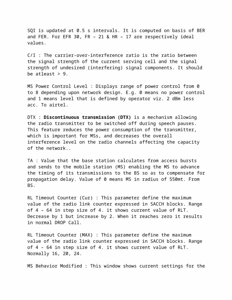
RxLev : Receiving level in terms of dBm that mobile is receiving from the site. Range of -30 dBm to -110dBm. RxQual : Quality of voice which is measured on basis of BER. Range of RxQual 0 -7. FER : Frame Error Rate it represents the percentage of frames being dropped due to high number of non-corrected bit errors in the frame. It is indication of voice quality in network. BER Actual : Ratio of the number of bit errors to the total number of bits transmitted in a given time interval. BER is a measure for the voice quality in network.. Depending on BER RxQual is measured. E,g, BER 0 to 0.2 % corresponds to RxQual 0. Max. BER countable and useful is up to 12.8 % which corresponds to RxQual of max. 7. SQI : SQI is a more sophisticated measure which is dedicated to reflecting the quality of the speech (as opposed to radio environment conditions). This means that when optimizing the speech quality in your network, SQI is the best criterion to use. SQI is updated at 0.5 s intervals. It is computed on basis of BER and FER. For EFR 30, FR – 21 & HR – 17 are respectively ideal values. C/I : The carrier-over-interference ratio is the ratio between the signal strength of the current serving cell and the signal strength of undesired (interfering) signal components. It should be atleast > 9.
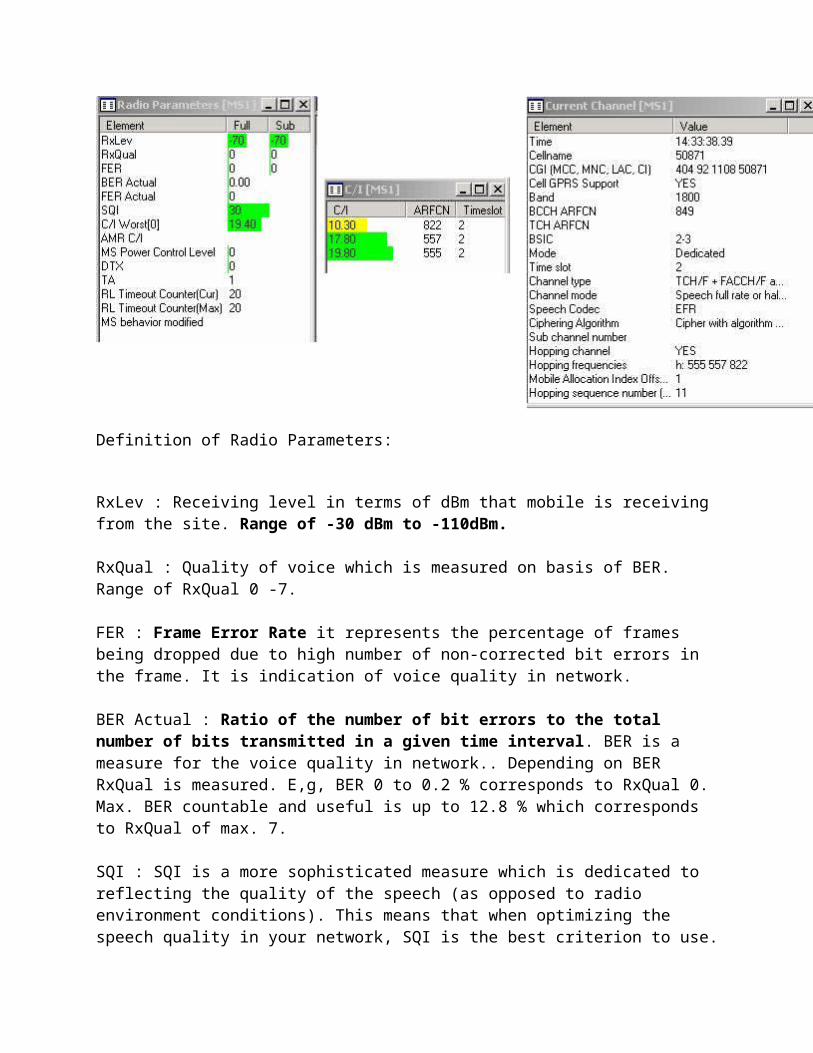
MS Power Control Level : Displays range of power control from 0 to 8 depending upon network design. E.g. 0 means no power control and 1 means level that is defined by operator viz. 2 dBm less acc. To airtel.
DTX : Discontinuous transmission (DTX) is a mechanism allowing the radio transmitter to be switched off during speech pauses. This feature reduces the power consumption of the transmitter, which is important for MSs, and decreases the overall interference level on the radio channels affecting the capacity of the network.. TA : Value that the base station calculates from access bursts and sends to the mobile station (MS) enabling the MS to advance the timing of its transmissions to the BS so as to compensate for propagation delay. Value of 0 means MS in radius of 550mt. From BS. RL Timeout Counter (Cur) : This parameter define the maximum value of the radio link counter expressed in SACCH blocks. Range of 4 – 64 in step size of 4. it shows current value of RLT. Decrease by 1 but increase by 2. When it reaches zero it results in normal DROP Call. RL Timeout Counter (MAX) : This parameter define the maximum value of the radio link counter expressed in SACCH blocks. Range of 4 – 64 in step size of 4. it shows current value of RLT. Normally 16, 20, 24. MS Behavior Modified : This window shows current settings for the mobile station, for instance whether handover is disabled or multiband reporting enabled.
Drive Test Procedure Part IV
GPRS (General Packet Radio System)
This is performed to check whether GPRS is working on the Site. This is doneby browsing a web page in browser of the phone. For GPRS to be checked it isnecessary to see that the handset is WAP, GPRS enabled.
Intra Site Handover
Intra Handover is performed to check whether handover is taking place both wayson the Site.Handover is performed among all the Sectors of the Site.
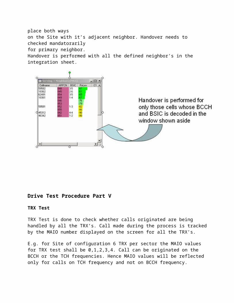
Inter Site Handover
Inter Handover is performed to check whether handover is taking place both wayson the Site with it’s adjacent neighbor. Handover needs to checked mandatorarilyfor primary neighbor.Handover is performed with all the defined neighbor's in the integration sheet.
Drive Test Procedure Part V
TRX Test
TRX Test is done to check whether calls originated are being handled by all the TRX’s. Call made during the process is tracked by the MAIO number displayed on the screen for all the TRX’s.
E.g. for Site of configuration 6 TRX per sector the MAIO values for TRX test shall be 0,1,2,3,4. Call can be originated on the BCCH or the TCH frequencies. Hence MAIO values will be reflected only for calls on TCH frequency and not on BCCH frequency.
Drive Test Procedure Part VI
Idle Drive is performed in two fashion
•Normal Drive •Frequency Lock Drive
Normal Drive
This is done to frame the potential area of the new site planned. It also helps us to get to know the important neighboring sites for which the handover has to take place.
Frequency Lock Drive
This is done by locking the BCCH frequency of the serving cell and performing the drive for the same cell unless the mobile enters into No Service Mode. This is use- ful for making decision related to GSM antenna height, tilt, and orientation.
Dedicated DriveDedicated drive is an important part of Drive Test. Here call is made to a test number and drive is done for the potential areas of the Site. During drive being carried out one has constantly monitor parameters such as RX Level, RX Quality, SQI, DTX, C/I Ratio, Hopping Channel, Neighbor list, TA (Timing Advance). Constant changes in these parameter are helpful for post Optimization of the site.
Rules during drive test:
1- Choose the site under surveying to be above the clutter and repeat types of the clutter you would be looking at.2- Any thing with clutter less than 100 is not enough.3- Make sure that the GPS surveying option is the same as the one used where the drive test is being performed.4- Make sure that the Dautch value of the GPS is the same as the one set for the country where the drive test is being made.5- Better collect data in the format of, Degrees: Decimal Points Degrees.6- Every 6 degrees you move result is one point change in the whole picture the UK being the reference point at 30, To the left it increases and to the right it decreases.7- Sampling rate, 40 Samples per 40 wavelengths. To reduce the effect of Radio fading.8- Sampling can be in Distance and Time. Better do it in Distance especially if you are driving in traffic jams.9- Do not drive away too much from the site.10- Drive in to the Site passing through the clutter as well as crossing the clutter

11- Try and drive many roads close to the site unless the clutter is so important.12- Try to avoid driving the same road twice.13- Do not drive over a bridge or in to a tunnel inside a clutter area, otherwise take that parts of data a out of the data file collected for this clutter.14- Make short calls and Long calls, Short calls is the average duration by customers, short calls are to know whether calls will survive the setup and the termination successfully, it also determines the setup time…15- Long calls are to test the hand over capabilities.16- Adjacent channels are channels with coverage of 9db more than the serving cell.17- The co-channel interference is interference from channels have frequency lower the serving channel.18- For the adjacent channel you could be served from this adjacent channel but the system can not read it and it gives the name of another channel19- The 6 neighboring cells are those who are listed in the scan list these do not mean that these are the only channels that the phone can see.20- You have to make sure of the values you are getting out of the surveying equipment do actually make sense.21- Know the exact power out of the antenna, ERP level, (Effective Radiation Power).22- Everything about the antenna conditions, during the test time should be reported in the final report.23- Weather conditions should be reported as well.24- Know the distance and direction of any buildings blocking your way.25- Finally, report all sorts of problems.
Handover Success Rate (HOSR):
If HOSR will be good TCH drop will also be good.If Handover success rate degrades call drop rate will take place.
Reasons for Poor HOSR:Improper Neighbor planning.CO-BCCH-BSIC issues in Neigh.Parameter Check.HSN clash.SL value.LAC boundary.DAC value mismatch.Syn mismatch.Overshoot.

HW Issues.Low Coverage
Solutions for removal of HOSR:
Arrange Drive Test:
The best way to find the real issues for HO fail make DT and check layer 3 msg for HO fail. By DT it is very easy to find the fail between cells.
Neighbor Tuning:
Try to retune neighborsAvoid CO-BCCH-BSIC neighbors.Avoid extra neighs.Delete long distance neighs.Check neighs are defined form both ends.If there are high fail delete and recreate neighs.
Parameter Check:1. Retune SL.It can change bw -90,-95,-105.2. Check HSN.3. Check SYN.4. Retune LDR, LUR, IDR, IUR.5. Retune LMRG, QMRG, PMRG.
DAC value Check:
Check DAC value. If DAC value is high or low tune it at the TH value. It should be 2050.
Overshoot:
When neighs are far away then chances of HO fail increases. In this case ping-pong HO takes place by which fail takes place. So if the inter distance is high it’s better to delete that kind of neighbor.
LAC Boundary-
Check LAC boundary.High fail takes place there will be Inter BSC cells.High fail takes place there will be Inter MSC cells.Define proper LAC in neigh cells.
HW Issues:Clear HW issues.

Check TRXs.Check outages.Check BOIA Card. Because if it is faulty incoming and outgoing HO will be fail.
Clear Reports:
Clear ZEAT.Clear 60.Clear 67.Clear 61.
Reports for HOSR :153 reports for HO fail bw two cells.154 HO analyses.60 for discrepancy.67 for Sync report.61 for one way neigh. ZEAT for CO-BCCH-BSIC neighs74 for HO definition report.ZELO for inter MSC HO report.150 for high HO fail.157 for high HO attempt and call ratio.158 for intra BSS HO observation.62 for Adj cell having same or adj freq.
TCH Blocking
When TCH is not allocated to the user after SD allocation, it is TCH Blocking.It is the failed call attempts which the MS user can notice.It takes place due to lack of TCH Resource.
Reasons for TCH Blocking:Some of them are-High Utilization of TCHTime slot faulty.Lock TRXs.HW Problem.
Solutions for removal of TCH Blocking:Implement half rate or Dual rate.Check FRL & FRU.Add another TRX. If TRX addition not possible, try to share the traffic of that
cell with the neighboring cell by changing tilt or orientation.
Useful Report for TCH Blocking:135 TCH Congestion.
Monday, March 29, 2010
TCH Drop
Drop during conversation is known as TCH drop. It takes place after connect ACK msg on TCH.TCH drop occurring. For TCH drop first cross check the BCCH of that cell, hardware issue may be, change RXP* and RLT** value. Find out there is any interference, neighbor defined.
Reasons for TCH Drop:Wrong Parameter Planning.BAD HOSR.Hardware Fault.High TR Fail.Overshoot.Outage.Due to Low Coverage.Due to ICM Band(CDMA)
Solutions for removal of TCH Drop:Check Parameter:Check the BCCH Plan (C/I or C/A). Co-BSIC & Co BCCH.Check the Timer T 100(should be 20 ms)Check Overshooting:If a cell is picking call from long distance, Check the sample log according to TA.Site Orientation.Effective tilt should be check.Mount position should be check
Improve HOSR:Check the Hopping plan.Check the Neighbor Plan
High TR Fail:Check and clear TR fail from oss end.
Bad Coverage:
If the drop call is due to low signal strength uplink, check the receive path of this particular TRX. Check receiver sensitivity, VSWR, feeder connection and etc. Drops due to Low Signal Strength.If the drop call reason is due to low signal strength downlink, then, check the transmit path. Check cards, feeder and etc.Use MapInfo or Google Earth to find location of sites.Effective tilt should be check.Mount position should be check.
Check HW:Check Alarms on site.Check TRXs.Check Slips.Check the Hopping plan.Check BB2F card.Check VSWR,Path imbalance.Connector Connection.Check TMA
Reports for TCH Drop:163 for TCH DropZEOL for alarms.ZAHP for Flicks.232 for TA report.208 Path Imbalance report.204 for BTS report.216 for all parameter.196 for UL-DL Qul.62 for Adj cell having same or adj freq.
NOTE:* Rxlev access min (RXP): With this parameter we define the minimum power level an MS has to receive before it is allowed to access the cell. Range: -110..-47 (dBm) Default: -105
**Radio link timeout (RLT): With this parameter we define the maximum value of the radio link counter expressed in SACCH blocks. Range: 4..64, with step size of 4 Default: 20
TCH Assignment
It’s a process of by which TCH is assigned to the MS. After the SD request MS gets TCH successfully and the call transfers to TCH it means TCH assignment is successful.For the best KPI TCH assignment should tend to 100%.It degrades due to HW problems.
Reasons for TCH Assignment failure:Hardware Fault(TRXs,Combiner,Duplexer,Cables)VSWRHigh Path Loss.Faulty TMA.High TCH Blocking.Loose connections.DR being used extensively
Solutions for removal of TCH Assignment:Clear VSWRIF TRXs are faulty lock them and try to replace them soon to avoid blocking.Path Imbalance clear.Connection from BTS to AntennaConnector connectionCheck TMA.Check Duplexer,Combiner,TRXs connections, Multicoupler etc.
Reports for TCH Assignment:ZEOL to check alarms208 for path imbalance196 for UL-DL interferenceZAHP for Flick report
SDCCH Drop
When we assigned SD for call origination and at that time due to some problem or any mismatch comes by which SD loss occurs, it is called as SD Drop.
It occurs between allocation of SD and before TCH allocation. Sometimes SD drop occurs because queuing is not activated in the system.
If SD drop is high plz look on parameters likeovershooting, shift the SD timeslot , may be hardware issue, interference, change the values of RXP, PMAX, may be issue of uplink or downlink issue in that cells for UL put a TMA
in that cell and for DL provide tilt ,re orient that antenna.
If SD Drop is high:If SD drop is high plz look on parameters like-OvershootingShift the SD time slotHardware issueInterferenceChange the values of RXP PMAXIt may be uplink or downlink issue in which cells for UL put a TMA in that cell and for DL provide tilt Re orient that antenna.
Reasons of SD Drop:Hardware Fault.Interference.MAIO mismatch.Bad Coverage.High TR Fail.Outage.Overshooting.Abis Drop.High Path Loss.Wrong Parameter Planning.Due to ICM Band(CDMA)High LAPD UtilizationHeavy blocking and DR feature being used extensively
Solutions for removal of SD Drop:
Interference:
Check the BCCH Plan (C/I or C/A).Co-BSIC & Co BCCH.Use latest ND 111 and MapInfo to find out proper frequency to reduce interference.
Arrange Drive Test:
The best way to find the real issues for Interference makes DT.Check interference by Interference scanning.Check clean BCCH by frequency scanning.
Overshooting:LAC Planning.If a cell is picking call from long distance,Check the sample log according to TA.
Cell orientation need to be defined according to clutter.Mount positionEffective Tilt
High TR Fail:Check and clear TR fail from OSS end.
Bad Coverage:
If the drop call is due to low signal strength uplink, check the receive path of this particular TRX. Check receiver sensitivity, VSWR, feeder connection and etc. Drops due to Low Signal Strength.If the drop call reason is due to low signal strength downlink, then, check the transmit path. Check cards, feeder and etc.Use MapInfo or Google Earth to find location of sites.
High LAPD Utilization:
Check LAPD util report from OSS, and define 32 kbps signaling instead of 16kbps.
Hardware Fault:Check Alarms.TRX condition.Check Path Imbalance.VSWR of the Cell.Connector Connection.Some times you will find issues on BCCH TRX.In this case BCCH shift from one to other TRX will reduce SD drop.
Check for parameter:Check the Timer T 3101Check the Timer T 200(20ms)T11 Expired(10 s)MAIO check.
Useful Reports for SD Drop:Use report ZEOL to find the alarms.Use 208 for Path loss analysis.Use 196 for UL-DL Interference.Use 163 report for SD drop.Use report 216 for detail SD Drop.232 report for TA report.62 for Adj cell having same or adj freq.ND 111 for freq plan.
204 for BTS and cell report.
Blocking and Congestion
Difference Between Blocking and Congestion:
It is very important to know difference between blocking and congestion. Some people think that both are same, but they differ from each other. If all the SD resources are full and not available for SD assign then its come into congestion. If at a particular time call is attempted and it fails then it known as Blocking.
SDCCH Blocking
SD blocking means that you are not getting SD resource for the call origination. When MS connects with NW then RACH and AGCH are provided. After AGCH,SDCCH is provided but if SDCCH is not provided at this time due some problems or due to unavailable of SD by BSC ,it’s called as SD Blocking. There are no of reasons for that.If such a case arises the customer will not be able to originate any call.
Reasons for SD Blocking:
Some of them are-
LAC boundary.HW Prob.
Solutions for removal of SD Blocking:
Here are some steps by which we can reduce SD Blocking-
1. Check the No. of SDCCH channel Available, if less then increase SD channel taking care that there is no TCH Blocking.2. Check LAC boundary, If location update is more then change theLAC of that site and set C2 and HYS.3. Use of Dynamic SDCCH (It is a BSC parameter and will be applied on whole BTS).4. Hardware check / shift SD to new time slot.5. Some times BMA and HYS parameters are useful to remove SDBlocking.
Usefull Reports For SD Blocking:
Use 182 to analyses SD Blocking reasons.130 for SD congestion.
40468015-Wcdma-Drive-Test-ProcedureWCDMA DRIVE TEST PROCEDURE:
WCDMA DRIVE TEST PROCEDURE PREPARED BY- GAURAV JAIN GTL JAIPUR
HOW TO INSTALL TEMS 9.1:
STEPS FOR INSTALLING TEMS 9.1 SOFTWARE 1-First install .Net 3 and .net 3.5 in your PC HOW TO INSTALL TEMS 9.1 2-Now install TEMS 9.1
Slide 3:
3-After installing TEMS, install the driver of Dongle, Mobile phone, and GPS Beffo cable by connecting the equipment in different ports. Dongle driver is automatically install in your PC just when you connect in your PC. But for Mobile and Beffo cable driver, you have to give the path of the driver.
Slide 4:
C:\Program Files\Ericsson\TEMS Products\TEMS Investigation\Application Folder. 5-Now open the TEMS window from. My Documents\TEMS Product Files\TEMS Investigation 9.1\Workspaces. In workspaces folder you have to open Investigation WCDMA GSM. 4-After installing device drivers, Copy and Paste above patch files in
For 2G Investigation:
For 2G Investigation You have to open 4 windows.. 1-GSM radio parameter 2-GSM current channel 3-GSM serving+Neighbour 4-Events First 3 windows is open from above toolbar Presentation-GSM And last window is open from Presentation- Signalling -Event Now connect the device by pressing the Green button(Connect all) or by pressing F2 button
For 2G Investigation:
For 2G Investigation
For Investigation WCDMA(3G) and GSM(2G) both i.e in Dual mode:
For Investigation WCDMA(3G) and GSM(2G) both i.e in Dual mode Along with 4 window of GSM you have to open 3 window more and they are.... 1-HSDPA analysis 2-WCDMA radio parameter 3-WCDMA Serving/ Active+Neighbrs The 1 st window i.e HSDPA analysis is used only for data call.. And remaining 2 is used for WCDMA analysis.
For Investigation WCDMA(3G) and GSM(2G) both i.e in Dual mode:
For Investigation WCDMA(3G) and GSM(2G) both i.e in Dual mode
For Investigation WCDMA(3G) and GSM(2G) both i.e in Dual mode:
For Investigation WCDMA(3G) and GSM(2G) both i.e in Dual mode The above window shows that you are latch in 3G network… During 3G network all the parameters in the 2G window are blank..
INTRODUCTION:
INTRODUCTION W CDMA Means Wideband Code Division Multiple Access. Wideband Code Division Multiple Access is a CDMA channel that is four times wider than the current channels that are typically used in 2G networks. Wideband CDMA has a bandwidth of 5 MHz or more . It is also called 3G system, allow for faster data transfer than GPRS and EDGE and also let you talk while you transfer data .
LOGICAL CHANNELS:
LOGICAL CHANNELS There are three available common control channels Broadcast control channel (BCCH) Paging channel (PCH) Forward access channel (FACH) Broadcast control channel (BCCH) carries system and cell specific information. Paging channel (PCH) for messages to the mobiles in the paging area. Forward access channel (FACH) for massages from the base station to the mobile in one cell. In addition, there are two dedicated channels Dedicated control channel (DCCH) covers the two dedicated control channel stand-alone dedicated channel (SDCCH) and associated control channel (ACCH). Dedicated traffic channel (DTCH) for point-to-point data transmission in the uplink and downlink.
UPGRADE GSM TO WCDMA:
UPGRADE GSM TO WCDMA The figure shows how a GSM system can be upgraded to offer WCDMA services. This diagram shows that 2 or more GSM channels are typically removed, replaced, or upgraded to have WCDMA modulation and transmission capability
DRIVE TEST:
DRIVE TEST Data Collection Requirements Processor and RAM requirements are strongly dependent on what external devices are connected and what tasks they perform. Two examples of recommended configurations are given here. One phone with default logs enabled (where applicable) and one GPS: 1.0 GHz Pentium class processor, 512 MB RAM Multiple phones with default logs enabled (and at most two phones engaging in data service testing), one scanner, and one GPS: 2.0 GHz Pentium class processor, 1 GB RAM Other hardware requirements: USB port for PCTel SeeGull LX Tri-band scanner USB port for HASP HL hardware key Serial port for PCTel SeeGull LX dual-band/single-band scanner (whether WCDMA or GSM)
WINDOW USED IN WCDMA DRIVE TEST:
WINDOW USED IN WCDMA DRIVE TEST
WCDMA RADIO PARAMETERS:
WCDMA RADIO PARAMETERS This windows shows the Radio Parameters of WCDMA
WCDMA SERVING/ACTIVE SET + NEIGHOURS:
WCDMA SERVING/ACTIVE SET + NEIGHOURS This windows shows the Serving cell & Neighbors AS : Active Set MN: Monitered Neighbors DN: Dominant Neighbors
HSDPA TESTING :
HSDPA TESTING It shows the Speed of HSDPA We consider Same window of HSUPA Analysis for the Speed Testing of HSUPA
HSDPA/HSUPA TESTING IN FTP SERVER:
HSDPA/HSUPA TESTING IN FTP SERVER We find out the Accurate Average Speed of HSDPA/ HSUPA through out the FTP
HSDPA/HSUPA TESTING:
HSDPA/HSUPA TESTING
HSDPA/HSUPA TESTING:
We also check the speed of HSDPA/HSUPA through NetPerSec, for this we check Current speed Average speed and Maximum speed of HSDPA & HSUPA HSDPA/HSUPA TESTING
RETU(REMOTE ELECTRICAL TILT UNIT):
RETU(REMOTE ELECTRICAL TILT UNIT) Two Cables are connected in RETU Dx1 Cable Tilt Monitor Cable RET Unit is monitered from RNC to maximize or minimize Electrical Tilt. Minimum tilt should be 0 & Maximum tilt should be 10 We have also update the type of antenna in RNC i.e. single band, dual band or tri band antenna. Also one Power Switch is in RET Unit. Upper press is ON & Down Press is OFF
RETU(REMOTE ELECTRICAL TILT UNIT):
RETU(REMOTE ELECTRICAL TILT UNIT)
Handover in UMTS or WCDMA:
Handover in UMTS or WCDMA There are 3 basic types of handover Intra frequency handovers Handovers between 2 UMTS carriers at the same frequency These can be soft handovers Inter frequency handovers Handovers between 2 UMTS carriers at different frequencies These are hard handovers Inter system handovers Handovers between UMTS and GSM carriers These are hard handovers These Handover also knows as IRAT Handover
THANK YOU:
THANK YOU