DRAWING INDEX Ritz-Craft TM FOR: BUILDER / CUSTOMER
26
Truss Fastening Details Cross Section Notes Cover Sheet 1st Floor Electrical Plan 1st Floor Plan Foundation Design Criteria Elevations N1 X2 SITE ADDRESS: FAS3 ELV1 FD E1 CS FP1 146 SALISBURY ROAD FRANKLIN, NH 03235 MERRIMACK County The enclosed drawings and specifications (referred hereinafter as subset) are the property of Ritz-Craft Corporation of PA, Inc. This subset is intended to show a specific plan or layout. This is intended to show the Ritz-Craft building module is in compliance with all state code requirements and standard engineering practices in order for the general contractor to obtain building permits. No part of this subset may be reproduced or used in any form or by any means without written authorization from Ritz-Craft Corporation Inc. This subset is proprietary and confidential. Any unauthorized use is prohibited. The drawings in this subset should not be scaled for dimensional reference. All dimension lines and notes supersede any such reference. Ritz-Craft Corporation Inc. will be considered a sub-contractor in all building projects, supplying a building component to a general contractor or builder. All notes with reference to "in-field", "by other", "on-site" and "by builder" are pertaining to the responsibilities of the general contractor. FOR: BUILDER / CUSTOMER DESCRIPTION: SHEET: DRAWING INDEX MODULE / ROOF LAYOUT: FRONT ELEVATION FOR ILLUSTRATIVE PURPOSES ONLY; SEE SALES AGREEMENT FOR ALL MATERIALS AND SPECIFICATIONS. 1st Floor Braced Wall Plan BW1 Module Fastening Details FAS4 Notes N2 Ritz-Craft Corporation of PA, Inc. 15 Industrial Park Road Mifflinburg, Pa 17844 MANUFACTURER INFORMATION Label Locations: As Noted. (HERS / Energy Star Label located at Kitchen Sink or Master Bedroom Closet) THIRD PARTY APPROVAL AGENCY ICC NTA LLC. 305 North Oakland Avenue Nappanee, IN 46500 (574)-773-7975 Cross Section X1 Truss Fastening Details FAS1 Module Fastening Details FAS2 Module Fastening Details FAS5 10/18/21 SUBSET MJJ 08/04/21 REV02 KLH 07/22/21 REV01 KLH 06/08/21 CONFIRM MJJ 2655921 SHEET: CO#: SN: 12575 PROFESSIONAL ENGINEER SEAL SCALE: TITLE: CUSTOMER: DATE NEW STYLE HOMES MONTAMBEAULT MODEL: VSR 7504 BUILDER: BY DESCRIPTION FRANKLIN , NH CHRIS SEEBOLD COPYRIGHT 2021. THIS DOCUMENT AND THE SUBJECT MATTER CONTAINED HEREIN IS PROPRIETARY AND MAY NOT BE REPRODUCED WITHOUT THE WRITTEN PERMISSION OF "RITZ-CRAFT CORPORATION" C Ritz-Craft TM COVER SHEET NTS CS
Transcript of DRAWING INDEX Ritz-Craft TM FOR: BUILDER / CUSTOMER

Truss Fastening Details
Cross Section
Notes
Cover Sheet
1st Floor Electrical Plan
1st Floor Plan
Foundation Design Criteria
Elevations
N1
X2
SITE ADDRESS:
FAS3
ELV1
FD
E1
CS
FP1
146 SALISBURY ROAD
FRANKLIN, NH 03235
MERRIMACK County
The enclosed drawings and specifications (referred hereinafter as subset) are the property of
Ritz-Craft Corporation of PA, Inc. This subset is intended to show a specific plan or layout.
This is intended to show the Ritz-Craft building module is in compliance with all state code
requirements and standard engineering practices in order for the general contractor to obtain
building permits. No part of this subset may be reproduced or used in any form or by any
means without written authorization from Ritz-Craft Corporation Inc. This subset is
proprietary and confidential. Any unauthorized use is prohibited.
The drawings in this subset should not be scaled for dimensional reference. All dimension
lines and notes supersede any such reference.
Ritz-Craft Corporation Inc. will be considered a sub-contractor in all building projects,
supplying a building component to a general contractor or builder. All notes with reference to
"in-field", "by other", "on-site" and "by builder" are pertaining to the responsibilities of the
general contractor.
FOR: BUILDER / CUSTOMER
DESCRIPTION:SHEET:
DRAWING INDEX
MODULE / ROOF LAYOUT:
FRONT ELEVATION
FOR ILLUSTRATIVE PURPOSES ONLY; SEE SALES AGREEMENT FOR ALL MATERIALS AND SPECIFICATIONS.
1st Floor Braced Wall PlanBW1
Module Fastening DetailsFAS4
NotesN2
Ritz-Craft Corporation
of PA, Inc.
15 Industrial Park Road
Mifflinburg, Pa 17844
MANUFACTURER INFORMATION
Label Locations:
As Noted. (HERS / Energy Star Label located at
Kitchen Sink or Master Bedroom Closet)
THIRD PARTY APPROVAL AGENCY
ICC NTA LLC.
305 North Oakland Avenue
Nappanee, IN 46500 (574)-773-7975
Cross SectionX1
Truss Fastening DetailsFAS1
Module Fastening DetailsFAS2
Module Fastening DetailsFAS5
10/18/21 SUBSET MJJ
08/04/21 REV02 KLH
07/22/21 REV01 KLH
06/08/21 CONFIRM MJJ
2655921
SHEET:
CO#:
SN:
12575
PROFESSIONAL ENGINEER SEAL
SCALE:
TITLE:
CUSTOMER:
DATE
NEW STYLE HOMES
MONTAMBEAULT
MODEL:
VSR 7504
BUILDER:
BYDESCRIPTION
FRANKLIN , NH
CHRIS SEEBOLD
COPYRIGHT 2021. THIS DOCUMENT AND THE SUBJECT
MATTER CONTAINED HEREIN IS PROPRIETARY AND MAY
N O T B E R E P R O D U C E D W I T H O U T T H E W R I T T E N
P E R M I S S I O N O F " R I T Z - C R A F T C O R P O R A T I O N "
C
Ritz-Craft
TM
COVER SHEET
NTS
CS

Model Number or Name:
Occupancy:
Building Area:
Construction Type:
No. of Stories Above Grade:
Mean Roof Height:
Min. Distance to Lot Line:
Exterior Wall Rating:
Ground Snow Load (Pg):
Roof Snow Load (Pf):
Minimum Roof Live Load:
Roof Dead Load:
Floor Live Load:
Floor Dead Load:
Wind Speed:
Wind Exposure:
Seismic Design Category:
Electrical Service Panel Size:
Additional Sub-Panel?
Permissible Gas Type:
Design Codes:
Thermal Climate Zone:
Degree Days:
Minimum Furnace Output:
Thermal Transmittance Values:
SQ. FT.
FT.
FT.
HR.
PSF
PSF
PSF
PSF
PSF
PSF
MPH V
asd
( V
ult
)
AMPS;
Floor* Wall* Roof*
DESIGN CRITERIA
ADDITIONAL SPECIAL CONDITIONS AND/OR LIMITATIONS AND/OR ITEMS
SUBJECT TO LOCAL INSPECTION:
* See RESCheck
1 and 2 Family Dwelling ( )
see Sheet N1
2655921
1586
70.8
40
90
B
C
20
10
10
N/A
Roof Pitch: / 12
Y N
VB VA
1
15.21
> 5
0
54.5
200
7
115
see RESCheck
see RESCheck
-
SITE ELEVATION: 470 ft ASL
NOTES:NEW HAMPSHIRE
2015 IRC, w/Amendments
2017 Edition NEC
2015 IECC, w/Amendments
10/18/21 SUBSET MJJ
08/04/21 REV02 KLH
07/22/21 REV01 KLH
06/08/21 CONFIRM MJJ
2655921
SHEET:
CO#:
SN:
12575
PROFESSIONAL ENGINEER SEAL
SCALE:
TITLE:
CUSTOMER:
DATE
NEW STYLE HOMES
MONTAMBEAULT
MODEL:
VSR 7504
BUILDER:
BYDESCRIPTION
FRANKLIN , NH
CHRIS SEEBOLD
COPYRIGHT 2021. THIS DOCUMENT AND THE SUBJECT
MATTER CONTAINED HEREIN IS PROPRIETARY AND MAY
N O T B E R E P R O D U C E D W I T H O U T T H E W R I T T E N
P E R M I S S I O N O F " R I T Z - C R A F T C O R P O R A T I O N "
C
Ritz-Craft
TM
NOTES
NTS
N1
10/18/21 SUBSET MJJ
08/04/21 REV02 KLH
07/22/21 REV01 KLH
06/08/21 CONFIRM MJJ
2655921
SHEET:
CO#:
SN:
12575
PROFESSIONAL ENGINEER SEAL
SCALE:
TITLE:
CUSTOMER:
DATE
NEW STYLE HOMES
MONTAMBEAULT
MODEL:
VSR 7504
BUILDER:
BYDESCRIPTION
FRANKLIN , NH
CHRIS SEEBOLD
COPYRIGHT 2021. THIS DOCUMENT AND THE SUBJECT
MATTER CONTAINED HEREIN IS PROPRIETARY AND MAY
N O T B E R E P R O D U C E D W I T H O U T T H E W R I T T E N
P E R M I S S I O N O F " R I T Z - C R A F T C O R P O R A T I O N "
C
Ritz-Craft
TM
NOTES
NTS
N2
10/18/21 SUBSET MJJ
08/04/21 REV02 KLH
07/22/21 REV01 KLH
06/08/21 CONFIRM MJJ
2655921
SHEET:
CO#:
SN:
12575
PROFESSIONAL ENGINEER SEAL
SCALE:
TITLE:
CUSTOMER:
DATE
NEW STYLE HOMES
MONTAMBEAULT
MODEL:
VSR 7504
BUILDER:
BYDESCRIPTION
FRANKLIN , NH
CHRIS SEEBOLD
COPYRIGHT 2021. THIS DOCUMENT AND THE SUBJECT
MATTER CONTAINED HEREIN IS PROPRIETARY AND MAY
N O T B E R E P R O D U C E D W I T H O U T T H E W R I T T E N
P E R M I S S I O N O F " R I T Z - C R A F T C O R P O R A T I O N "
C
Ritz-Craft
TM
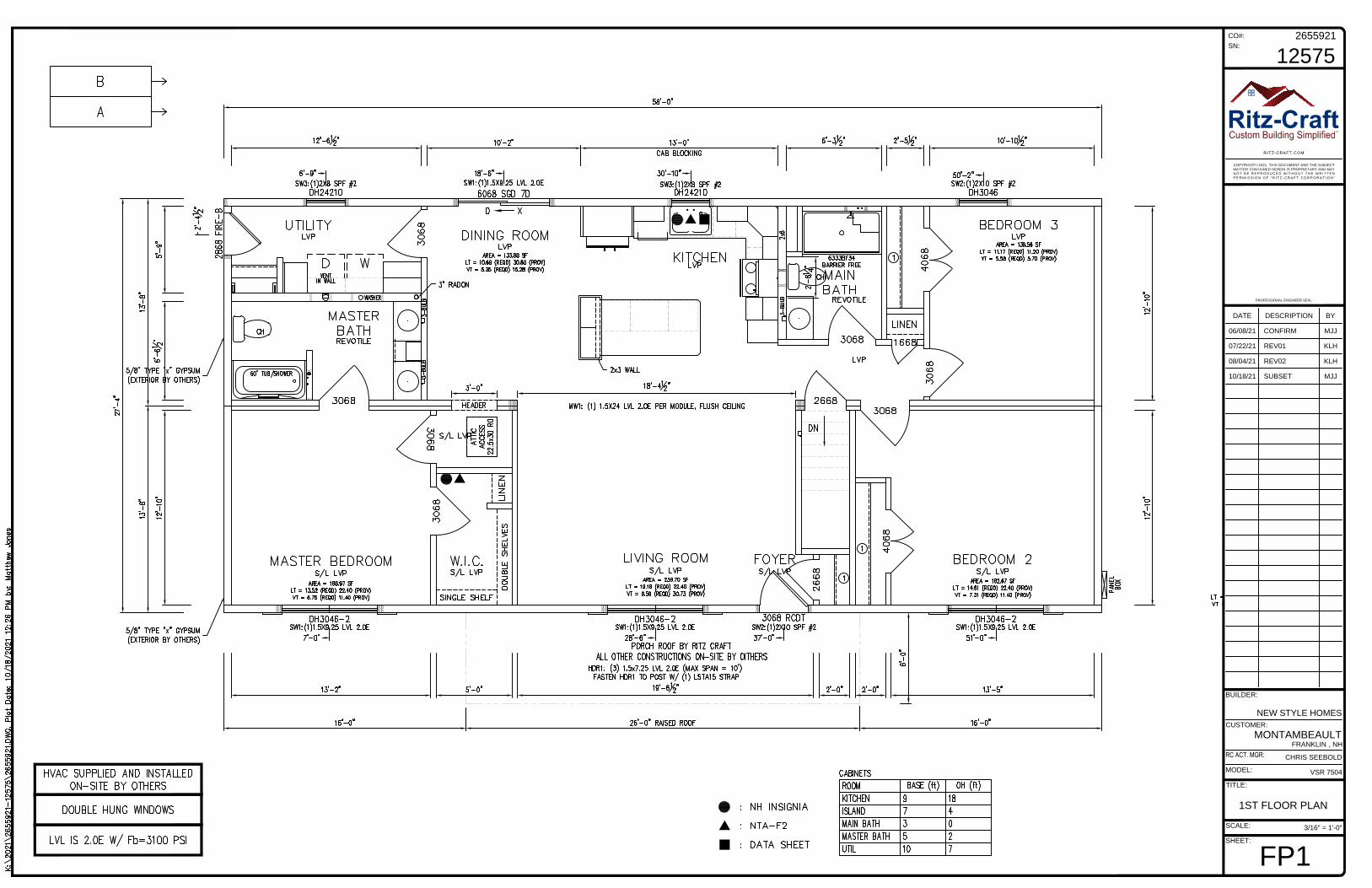
1ST FLOOR PLAN
3/16" = 1'-0"
FP1

Timer
10/18/21 SUBSET MJJ
08/04/21 REV02 KLH
07/22/21 REV01 KLH
06/08/21 CONFIRM MJJ
2655921
SHEET:
CO#:
SN:
12575
PROFESSIONAL ENGINEER SEAL
SCALE:
TITLE:
CUSTOMER:
DATE
NEW STYLE HOMES
MONTAMBEAULT
MODEL:
VSR 7504
BUILDER:
BYDESCRIPTION
FRANKLIN , NH
CHRIS SEEBOLD
COPYRIGHT 2021. THIS DOCUMENT AND THE SUBJECT
MATTER CONTAINED HEREIN IS PROPRIETARY AND MAY
N O T B E R E P R O D U C E D W I T H O U T T H E W R I T T E N
P E R M I S S I O N O F " R I T Z - C R A F T C O R P O R A T I O N "
C
Ritz-Craft
TM
1ST FLOOR
ELECTRICAL PLAN
3/16" = 1'-0"
E1

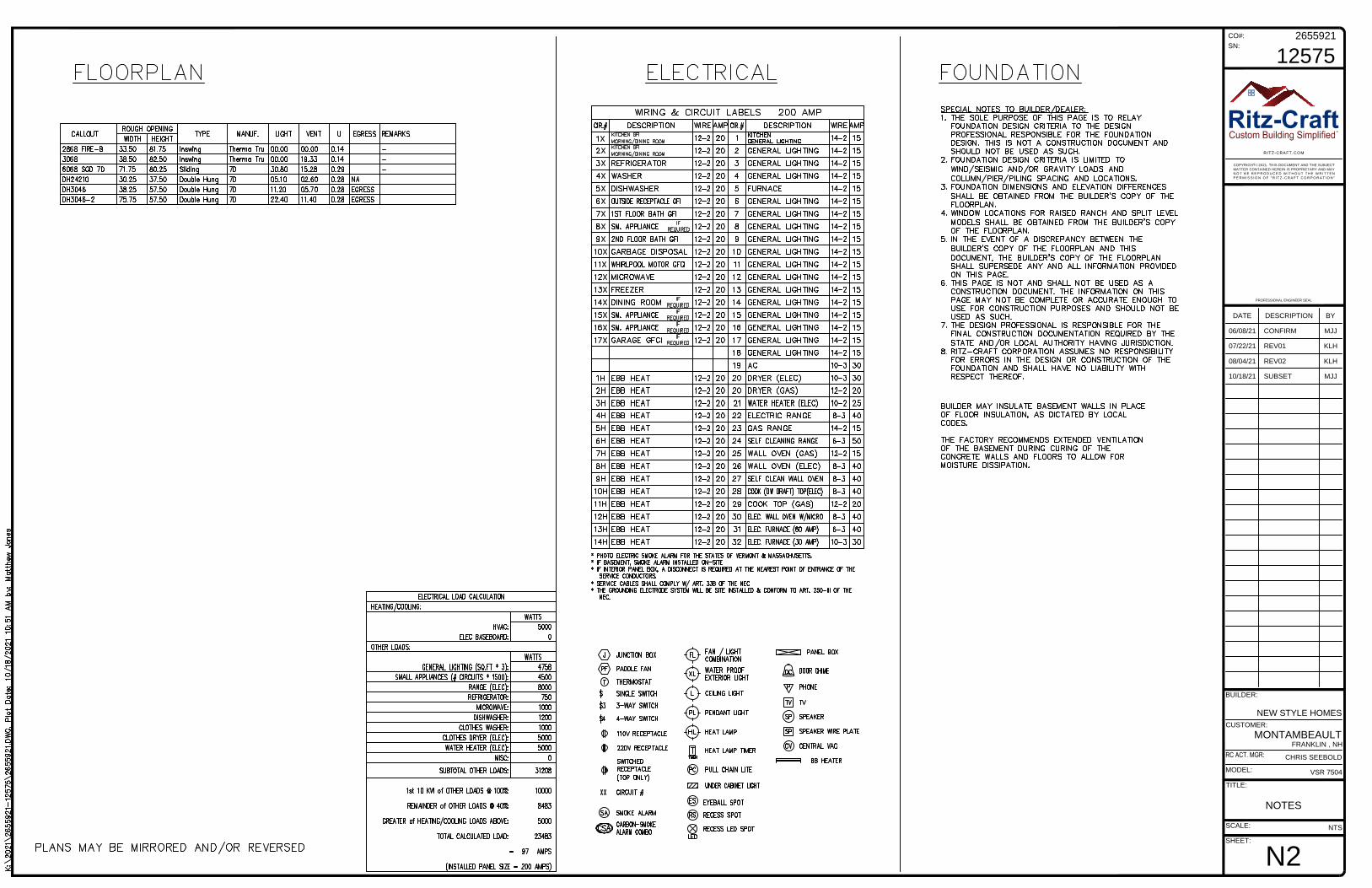
SPECIAL NOTES TO BUILDER/DEALER:
1. THE SOLE PURPOSE OF THIS PAGE IS TO RELAY FOUNDATION DESIGN CRITERIA TO THE DESIGN PROFESSIONAL RESPONSIBLE FOR THE FOUNDATION DESIGN. THIS IS NOT A CONSTRUCTION
DOCUMENT AND SHOULD NOT BE USED AS SUCH.
2. FOUNDATION DESIGN CRITERIA IS LIMITED TO WIND/SEISMIC AND/OR GRAVITY LOADS AND COLUMN/PIER/PILING SPACING AND LOCATIONS.
3. FOUNDATION DIMENSIONS AND ELEVATION DIFFERENCES SHALL BE OBTAINED FROM THE BUILDER'S COPY OF THE FLOORPLAN.
4. WINDOW LOCATIONS FOR RAISED RANCH AND SPLIT LEVEL MODELS SHALL BE OBTAINED FROM THE BUILDER'S COPY OF THE FLOORPLAN.
5. IN THE EVENT OF A DISCREPANCY BETWEEN THE BUILDER'S COPY OF THE FLOORPLAN AND THIS DOCUMENT, THE BUILDER'S COPY OF THE FLOORPLAN SHALL SUPERSEDE ANY AND ALL
INFORMATION PROVIDED ON THIS PAGE.
6. THIS PAGE IS NOT AND SHALL NOT BE USED AS A CONSTRUCTION DOCUMENT. THE INFORMATION ON THIS PAGE MAY NOT BE COMPLETE OR ACCURATE ENOUGH TO USE FOR CONSTRUCTION
PURPOSES AND SHOULD NOT BE USED AS SUCH.
7. THE DESIGN PROFESSIONAL IS RESPONSIBLE FOR THE FINAL CONSTRUCTION DOCUMENTATION REQUIRED BY THE STATE AND/OR LOCAL AUTHORITY HAVING JURISDICTION.
8. RITZ-CRAFT CORPORATION ASSUMES NO RESPONSIBILITY FOR ERRORS IN THE DESIGN OR CONSTRUCTION OF THE FOUNDATION AND SHALL HAVE NO LIABILITY WITH RESPECT THEREOF.
9. THIS PAGE REFLECTS THE DIMENSIONS OF THE MODULAR FLOORPLAN. ANY PLANNED GAPS AT THE MARRIAGE WALL WILL REQUIRE ADJUSTMENTS TO THE FOUNDATION PLAN.
10/18/21 SUBSET MJJ
08/04/21 REV02 KLH
07/22/21 REV01 KLH
06/08/21 CONFIRM MJJ
2655921
SHEET:
CO#:
SN:
12575
PROFESSIONAL ENGINEER SEAL
SCALE:
TITLE:
CUSTOMER:
DATE
NEW STYLE HOMES
MONTAMBEAULT
MODEL:
VSR 7504
BUILDER:
BYDESCRIPTION
FRANKLIN , NH
CHRIS SEEBOLD
COPYRIGHT 2021. THIS DOCUMENT AND THE SUBJECT
MATTER CONTAINED HEREIN IS PROPRIETARY AND MAY
N O T B E R E P R O D U C E D W I T H O U T T H E W R I T T E N
P E R M I S S I O N O F " R I T Z - C R A F T C O R P O R A T I O N "
C
Ritz-Craft
TM
FOUNDATION
DESIGN CRITERIA
3/16" = 1'-0"
FD

10/18/21 SUBSET MJJ
08/04/21 REV02 KLH
07/22/21 REV01 KLH
06/08/21 CONFIRM MJJ
2655921
SHEET:
CO#:
SN:
12575
PROFESSIONAL ENGINEER SEAL
SCALE:
TITLE:
CUSTOMER:
DATE
NEW STYLE HOMES
MONTAMBEAULT
MODEL:
VSR 7504
BUILDER:
BYDESCRIPTION
FRANKLIN , NH
CHRIS SEEBOLD
COPYRIGHT 2021. THIS DOCUMENT AND THE SUBJECT
MATTER CONTAINED HEREIN IS PROPRIETARY AND MAY
N O T B E R E P R O D U C E D W I T H O U T T H E W R I T T E N
P E R M I S S I O N O F " R I T Z - C R A F T C O R P O R A T I O N "
C
Ritz-Craft
TM
ELEVATIONS
1/8" = 1'-0"
ELV1
A
B
1 2
10/18/21 SUBSET MJJ
08/04/21 REV02 KLH
07/22/21 REV01 KLH
06/08/21 CONFIRM MJJ
2655921
SHEET:
CO#:
SN:
12575
PROFESSIONAL ENGINEER SEAL
SCALE:
TITLE:
CUSTOMER:
DATE
NEW STYLE HOMES
MONTAMBEAULT
MODEL:
VSR 7504
BUILDER:
BYDESCRIPTION
FRANKLIN , NH
CHRIS SEEBOLD
COPYRIGHT 2021. THIS DOCUMENT AND THE SUBJECT
MATTER CONTAINED HEREIN IS PROPRIETARY AND MAY
N O T B E R E P R O D U C E D W I T H O U T T H E W R I T T E N
P E R M I S S I O N O F " R I T Z - C R A F T C O R P O R A T I O N "
C
Ritz-Craft
TM
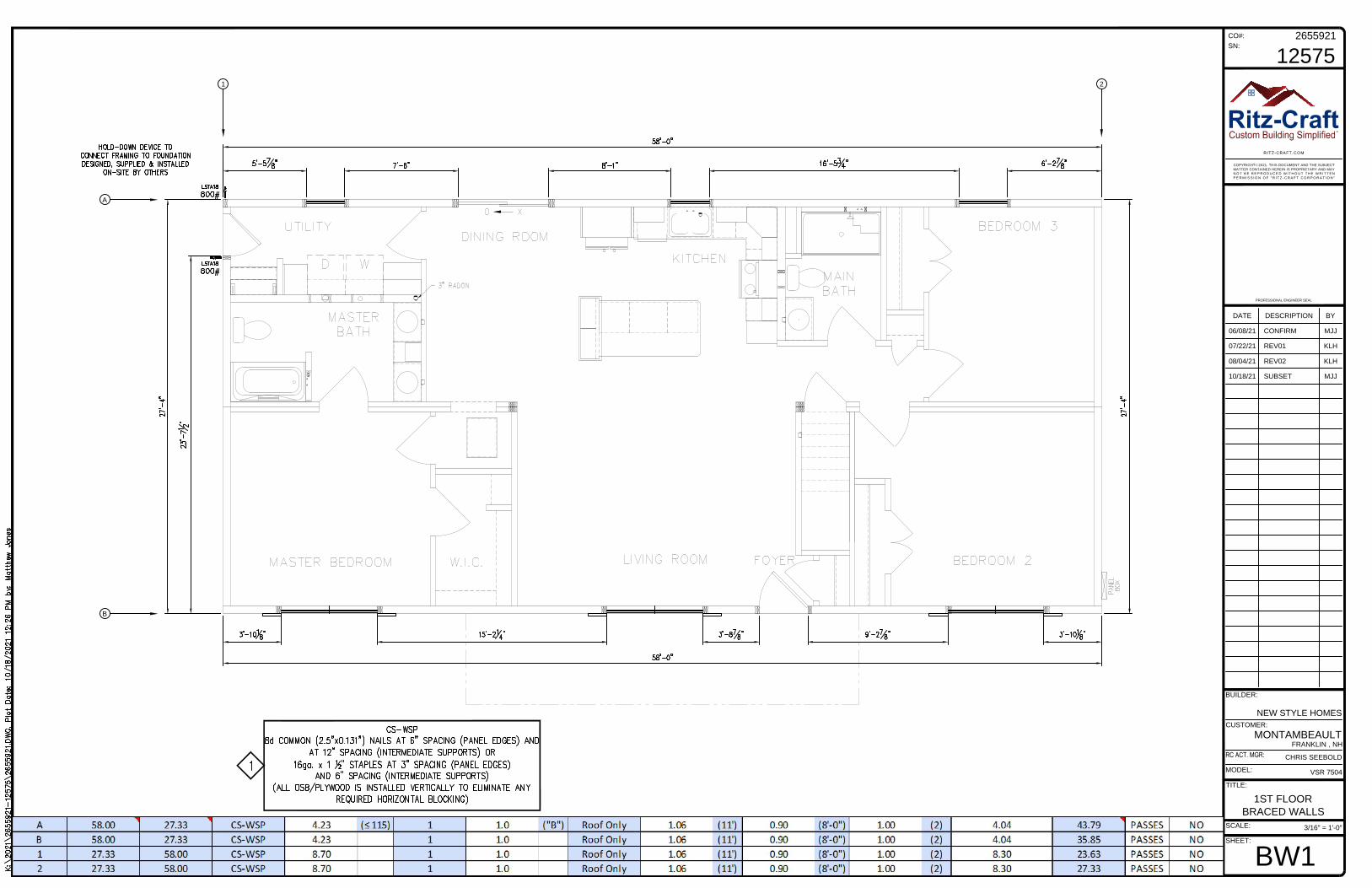
1ST FLOOR
BRACED WALLS
3/16" = 1'-0"
BW1

10/18/21 SUBSET MJJ
08/04/21 REV02 KLH
07/22/21 REV01 KLH
06/08/21 CONFIRM MJJ
2655921
SHEET:
CO#:
SN:
12575
PROFESSIONAL ENGINEER SEAL
SCALE:
TITLE:
CUSTOMER:
DATE
NEW STYLE HOMES
MONTAMBEAULT
MODEL:
VSR 7504
BUILDER:
BYDESCRIPTION
FRANKLIN , NH
CHRIS SEEBOLD
COPYRIGHT 2021. THIS DOCUMENT AND THE SUBJECT
MATTER CONTAINED HEREIN IS PROPRIETARY AND MAY
N O T B E R E P R O D U C E D W I T H O U T T H E W R I T T E N
P E R M I S S I O N O F " R I T Z - C R A F T C O R P O R A T I O N "
C
Ritz-Craft
TM
SECTION
0.024644
X1

10/18/21 SUBSET MJJ
08/04/21 REV02 KLH
07/22/21 REV01 KLH
06/08/21 CONFIRM MJJ
2655921
SHEET:
CO#:
SN:
12575
PROFESSIONAL ENGINEER SEAL
SCALE:
TITLE:
CUSTOMER:
DATE
NEW STYLE HOMES
MONTAMBEAULT
MODEL:
VSR 7504
BUILDER:
BYDESCRIPTION
FRANKLIN , NH
CHRIS SEEBOLD
COPYRIGHT 2021. THIS DOCUMENT AND THE SUBJECT
MATTER CONTAINED HEREIN IS PROPRIETARY AND MAY
N O T B E R E P R O D U C E D W I T H O U T T H E W R I T T E N
P E R M I S S I O N O F " R I T Z - C R A F T C O R P O R A T I O N "
C
Ritz-Craft
TM
SECTION
0.024644
X2
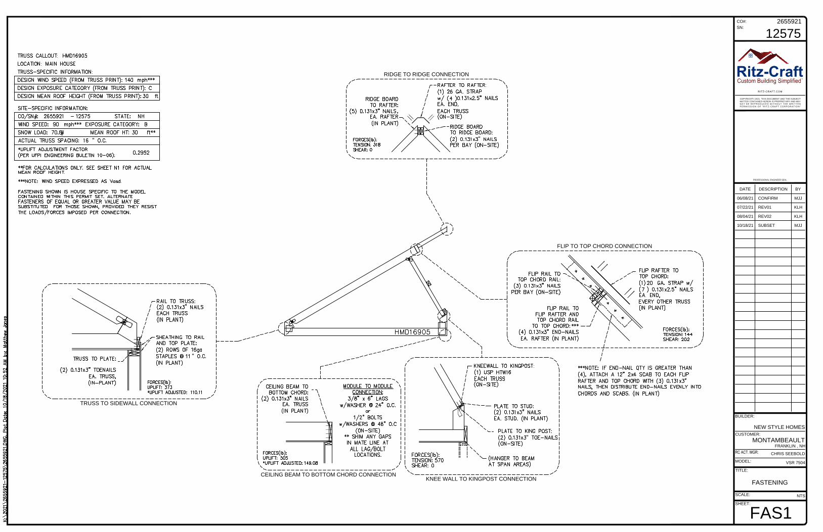
FLIP TO TOP CHORD CONNECTION
RIDGE TO RIDGE CONNECTION
KNEE WALL TO KINGPOST CONNECTION
TRUSS TO SIDEWALL CONNECTION
CEILING BEAM TO BOTTOM CHORD CONNECTION
10/18/21 SUBSET MJJ
08/04/21 REV02 KLH
07/22/21 REV01 KLH
06/08/21 CONFIRM MJJ
2655921
SHEET:
CO#:
SN:
12575
PROFESSIONAL ENGINEER SEAL
SCALE:
TITLE:
CUSTOMER:
DATE
NEW STYLE HOMES
MONTAMBEAULT
MODEL:
VSR 7504
BUILDER:
BYDESCRIPTION
FRANKLIN , NH
CHRIS SEEBOLD
COPYRIGHT 2021. THIS DOCUMENT AND THE SUBJECT
MATTER CONTAINED HEREIN IS PROPRIETARY AND MAY
N O T B E R E P R O D U C E D W I T H O U T T H E W R I T T E N
P E R M I S S I O N O F " R I T Z - C R A F T C O R P O R A T I O N "
C
Ritz-Craft
TM
FASTENING
NTS
FAS1
10/18/21 SUBSET MJJ
08/04/21 REV02 KLH
07/22/21 REV01 KLH
06/08/21 CONFIRM MJJ
2655921
SHEET:
CO#:
SN:
12575
PROFESSIONAL ENGINEER SEAL
SCALE:
TITLE:
CUSTOMER:
DATE
NEW STYLE HOMES
MONTAMBEAULT
MODEL:
VSR 7504
BUILDER:
BYDESCRIPTION
FRANKLIN , NH
CHRIS SEEBOLD
COPYRIGHT 2021. THIS DOCUMENT AND THE SUBJECT
MATTER CONTAINED HEREIN IS PROPRIETARY AND MAY
N O T B E R E P R O D U C E D W I T H O U T T H E W R I T T E N
P E R M I S S I O N O F " R I T Z - C R A F T C O R P O R A T I O N "
C
Ritz-Craft
TM
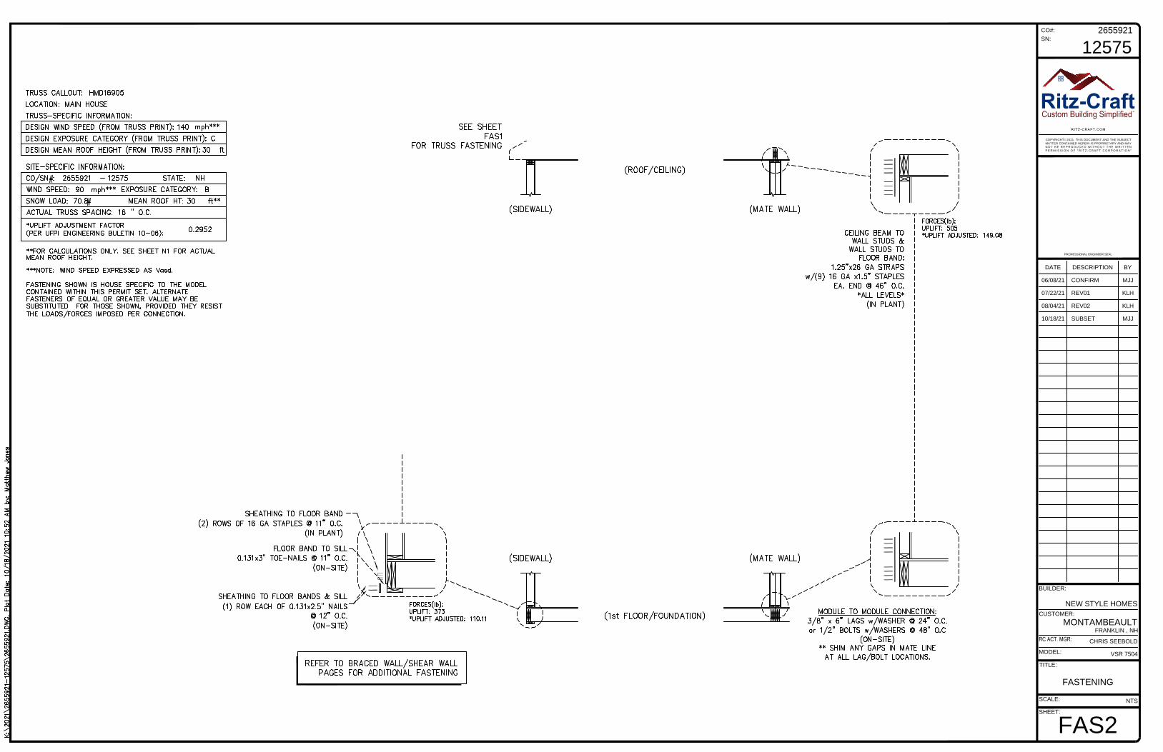
FASTENING
NTS
FAS2

FLIP TO TOP CHORD CONNECTION
RIDGE TO RIDGE CONNECTION
KNEE WALL TO KINGPOST CONNECTION
KNEE WALL TO BOTTOM CHORD CONNECTION
SHIP LOOSE KNEE WALL TO TOP CHORD CONNECTION
TRUSS TO SIDEWALL CONNECTION
FLIP TO TOP CHORD CONNECTION
CEILING BEAM TO BOTTOM CHORD CONNECTION
10/18/21 SUBSET MJJ
08/04/21 REV02 KLH
07/22/21 REV01 KLH
06/08/21 CONFIRM MJJ
2655921
SHEET:
CO#:
SN:
12575
PROFESSIONAL ENGINEER SEAL
SCALE:
TITLE:
CUSTOMER:
DATE
NEW STYLE HOMES
MONTAMBEAULT
MODEL:
VSR 7504
BUILDER:
BYDESCRIPTION
FRANKLIN , NH
CHRIS SEEBOLD
COPYRIGHT 2021. THIS DOCUMENT AND THE SUBJECT
MATTER CONTAINED HEREIN IS PROPRIETARY AND MAY
N O T B E R E P R O D U C E D W I T H O U T T H E W R I T T E N
P E R M I S S I O N O F " R I T Z - C R A F T C O R P O R A T I O N "
C
Ritz-Craft
TM
FASTENING
NTS
FAS3

10/18/21 SUBSET MJJ
08/04/21 REV02 KLH
07/22/21 REV01 KLH
06/08/21 CONFIRM MJJ
2655921
SHEET:
CO#:
SN:
12575
PROFESSIONAL ENGINEER SEAL
SCALE:
TITLE:
CUSTOMER:
DATE
NEW STYLE HOMES
MONTAMBEAULT
MODEL:
VSR 7504
BUILDER:
BYDESCRIPTION
FRANKLIN , NH
CHRIS SEEBOLD
COPYRIGHT 2021. THIS DOCUMENT AND THE SUBJECT
MATTER CONTAINED HEREIN IS PROPRIETARY AND MAY
N O T B E R E P R O D U C E D W I T H O U T T H E W R I T T E N
P E R M I S S I O N O F " R I T Z - C R A F T C O R P O R A T I O N "
C
Ritz-Craft
TM
FASTENING
NTS
FAS4

10/18/21 SUBSET MJJ
08/04/21 REV02 KLH
07/22/21 REV01 KLH
06/08/21 CONFIRM MJJ
2655921
SHEET:
CO#:
SN:
12575
PROFESSIONAL ENGINEER SEAL
SCALE:
TITLE:
CUSTOMER:
DATE
NEW STYLE HOMES
MONTAMBEAULT
MODEL:
VSR 7504
BUILDER:
BYDESCRIPTION
FRANKLIN , NH
CHRIS SEEBOLD
COPYRIGHT 2021. THIS DOCUMENT AND THE SUBJECT
MATTER CONTAINED HEREIN IS PROPRIETARY AND MAY
N O T B E R E P R O D U C E D W I T H O U T T H E W R I T T E N
P E R M I S S I O N O F " R I T Z - C R A F T C O R P O R A T I O N "
C
Ritz-Craft
TM
FASTENING
NTS
FAS5
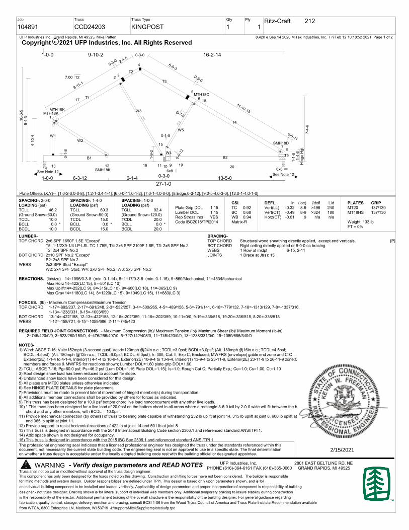
Job
104891
Truss
CCD24203
Truss Type
KINGPOST
Qty
1
Ply
1Ritz-Craft 212
8.420 e Sep 14 2020 MiTek Industries, Inc. Fri Feb 12 10:18:52 2021 Page 1 of 2UFP Industries Inc., Grand Rapids, MI 49525, Mike Patten
[P]
Provide support to resist horizontal reactions of 422 lb at joint 14 and 501 lb at joint 8
See Note 12See Note 12
- Verify design parameters and READ NOTES
an individual building component to be installed and loaded vertically. Applicability of design parameters and proper incorporation of component is responsibility of building
designer - not truss designer. Bracing shown is for lateral support of individual web members only. Additional temporary bracing to insure stability during construction
is the responsibility of the erector. Additional permanent bracing of the overall structure is the responsibility of the building designer. For general guidance regarding
fabrication, quality control, storage, delivery, erection and bracing, consult BCSI 1-06 from the Wood Truss Council of America and Truss Plate Institute Recommendation available
from WTCA, 6300 Enterprise LN, Madison, WI 53719 J:\support\MitekSupp\templates\ufp.tpe
WARNING
C
UFP Industries, Inc. 2801 EAST BELTLINE RD, NEPHONE (616)-364-6161 FAX (616)-365-0060 GRAND RAPIDS, MI 49525
This component has only been designed for the loads noted on this drawing. Construction and lifting forces have not been considered. The builder is responsible
for lifting methods and system design. Builder responsibilities are defined under TPI1. This design is based only upon parameters shown, and is for
The professional engineering seal indicates that a licensed professional engineer has designed the truss under the standards referenced within thisdocument, not necessarily the current state building code. The engineering seal is not an approval to use in a specific state. The final determinationon whether a truss design is acceptable under the locally adopted building code rest with the building official or designated appointee.
Truss shall not be cut or modified without approval of the truss design engineer.
Copyright 2021 UFP Industries, Inc. All Rights Reserved
B1
T1
T5
W2
W1
B2
W4
T4
T3
W5
T2
W3
1
23
4
5
6
78
13 12 11 10 9
15
17 18
1416 19
20
MTH18K
6x8
SMH18D
SMH18K 6x8
MTH18C
4-1
0-4
9-4
-3
1-9
-2
1-4
-6H
ing
e H
gt.
7-4
-6
0-3-0
2-1-0
0-3-0
8-11-1
6-0-3
0-3-0
0-7-8
11-10-15
0-5-11
0-0
-12
0-1
-8
0-1-8
1-0-0 6-3-12 6-1-4 0-3-0 13-5-0
27-1-0
1-0-0 9-10-2 16-2-14
10
-6-5
1-1
-8
7.00 12
Plate Offsets (X,Y)-- [1:0-2-0,0-0-8], [1:2-1-3,4-1-4], [6:0-0-11,0-1-2], [7:0-1-4,0-0-0], [8:Edge,0-3-12], [9:0-5-4,0-3-0], [12:0-1-4,0-1-0]
SPACING-: 2-0-0LOADING (psf)TCLL(Ground Snow=60.0)TCDLBCLLBCDL
46.2
10.00.0 *
10.0
SPACING-: 1-4-0LOADING (psf)TCLL(Ground Snow=90.0)TCDLBCLLBCDL
69.3
15.00.0 *
15.0
SPACING-: 1-0-0LOADING (psf)TCLL(Ground Snow=120.0)TCDLBCLLBCDL
92.4
20.00.0 *
20.0
Plate Grip DOLLumber DOLRep Stress IncrCode
1.151.15YES
IBC2018/TPI2014
CSI.TCBCWBMatrix-R
0.920.680.94
DEFL.Vert(LL)Vert(CT)Horz(CT)
in-0.32-0.49-0.01
(loc)8-98-9
9
l/defl>496>324
n/a
L/d240180n/a
PLATESMT20MT18HS
Weight: 133 lbFT = 0%
GRIP137/130137/130
LUMBER-TOP CHORD 2x6 SPF 1650F 1.5E *Except*
T5: 1-1/2X9-1/4 LP-LSL TC 1.75E, T4: 2x6 SPF 2100F 1.8E, T3: 2x6 SPF No.2T2: 2x4 SPF No.2
BOT CHORD 2x10 SPF No.2 *Except*B2: 2x8 SPF No.2
WEBS 2x3 SPF Stud *Except*W2: 2x4 SPF Stud, W4: 2x8 SPF No.2, W3: 2x3 SPF No.2
BRACING-TOP CHORD Structural wood sheathing directly applied, except end verticals.BOT CHORD Rigid ceiling directly applied or 6-0-0 oc bracing.WEBS 1 Row at midpt 6-15, 2-11JOINTS 1 Brace at Jt(s): 15
REACTIONS. (lb/size) 14=1096/0-3-8 (min. 0-1-14), 8=1117/0-3-8 (min. 0-1-15), 9=860/Mechanical, 11=453/MechanicalMax Horz 14=422(LC 15), 8=-501(LC 10)Max Uplift14=-252(LC 9), 8=-315(LC 10), 9=-600(LC 10), 11=-365(LC 9)Max Grav14=1180(LC 14), 8=1220(LC 15), 9=1049(LC 15), 11=683(LC 3)
FORCES. (lb) - Maximum Compression/Maximum TensionTOP CHORD 1-17=-893/237, 2-17=-691/248, 2-3=-532/257, 3-4=-500/265, 4-5=-489/156, 5-6=-791/141, 6-18=-779/132, 7-18=-1313/129, 7-8=-1337/316,
1-13=-1238/331, 9-15=-1003/650BOT CHORD 13-14=-422/158, 12-13=-422/158, 12-16=-202/359, 11-16=-202/359, 10-11=0/0, 9-19=-336/518, 19-20=-336/518, 8-20=-336/518WEBS 1-12=-158/721, 6-15=-1059/686, 2-11=-745/420
REQUIRED FIELD JOINT CONNECTIONS - Maximum Compression (lb)/ Maximum Tension (lb)/ Maximum Shear (lb)/ Maximum Moment (lb-in)2=745/420/0/0, 3=523/260/150/0, 4=476/266/407/0, 5=727/142/408/0, 11=745/420/0/0, 13=1238/331/0/0, 15=1059/686/340/0
NOTES-1) Wind: ASCE 7-16; Vult=152mph (3-second gust) Vasd=120mph @24in o.c.; TCDL=3.0psf; BCDL=3.0psf; (Alt. 180mph @16in o.c.; TCDL=4.5psf;
BCDL=4.5psf); (Alt. 180mph @12in o.c.; TCDL=6.0psf; BCDL=6.0psf); h=30ft; Cat. II; Exp C; Enclosed; MWFRS (envelope) gable end zone and C-CExterior(2E) 1-1-4 to 4-1-4, Interior(1) 4-1-4 to 10-9-4, Exterior(2E) 10-9-4 to 13-9-4, Interior(1) 13-9-4 to 23-11-9, Exterior(2E) 23-11-9 to 26-11-9 zone;C-C formembers and forces & MWFRS for reactions shown; Lumber DOL=1.60 plate grip DOL=1.60
2) TCLL: ASCE 7-16; Pg=60.0 psf; Ps=46.2 psf (Lum DOL=1.15 Plate DOL=1.15); Is=1.0; Rough Cat C; Partially Exp.; Ce=1.0; Cs=1.00; Ct=1.103) Roof design snow load has been reduced to account for slope.4) Unbalanced snow loads have been considered for this design.5) All plates are MT20 plates unless otherwise indicated.6) See HINGE PLATE DETAILS for plate placement.7) Provisions must be made to prevent lateral movement of hinged member(s) during transportation.8) All additional member connections shall be provided by others for forces as indicated.9) This truss has been designed for a 10.0 psf bottom chord live load nonconcurrent with any other live loads.10) * This truss has been designed for a live load of 20.0psf on the bottom chord in all areas where a rectangle 3-6-0 tall by 2-0-0 wide will fit between the bottom
chord and any other members, with BCDL = 10.0psf.11) Provide mechanical connection (by others) of truss to bearing plate capable of withstanding 252 lb uplift at joint 14, 315 lb uplift at joint 8, 600 lb uplift at joint 9
and 365 lb uplift at joint 11.12)13) This truss is designed in accordance with the 2018 International Building Code section 2306.1 and referenced standard ANSI/TPI 1.14) Attic space shown is not designed for occupancy.15) This truss is designed in accordance with the 2015 IBC Sec 2306.1 and referenced standard ANSI/TPI 1
MTH18K
2/15/2021

16) Take precaution to keep the chords in plane, any bending or twisting of the hinge plate must be repaired before the building is put into service.17) The field-installed members are an integral part of the truss design. Retain a design professional to specify final field connections and temporary supports. All
field-installed members must be properly fastened prior to applying any loading to the truss. This design anticipates the final set position.
- Verify design parameters and READ NOTES
an individual building component to be installed and loaded vertically. Applicability of design parameters and proper incorporation of component is responsibility of building
designer - not truss designer. Bracing shown is for lateral support of individual web members only. Additional temporary bracing to insure stability during construction
is the responsibility of the erector. Additional permanent bracing of the overall structure is the responsibility of the building designer. For general guidance regarding
fabrication, quality control, storage, delivery, erection and bracing, consult BCSI 1-06 from the Wood Truss Council of America and Truss Plate Institute Recommendation available
from WTCA, 6300 Enterprise LN, Madison, WI 53719 J:\support\MitekSupp\templates\ufp.tpe
WARNING UFP Industries, Inc. 2801 EAST BELTLINE RD, NEPHONE (616)-364-6161 FAX (616)-365-0060 GRAND RAPIDS, MI 49525
This component has only been designed for the loads noted on this drawing. Construction and lifting forces have not been considered. The builder is responsible
for lifting methods and system design. Builder responsibilities are defined under TPI1. This design is based only upon parameters shown, and is for
The professional engineering seal indicates that a licensed professional engineer has designed the truss under the standards referenced within thisdocument, not necessarily the current state building code. The engineering seal is not an approval to use in a specific state. The final determinationon whether a truss design is acceptable under the locally adopted building code rest with the building official or designated appointee.
Truss shall not be cut or modified without approval of the truss design engineer.
Job
104891
Truss
CCD24203
Truss Type
KINGPOST
Qty
1
Ply
1Ritz-Craft 212
8.420 e Sep 14 2020 MiTek Industries, Inc. Fri Feb 12 10:18:52 2021 Page 2 of 2UFP Industries Inc., Grand Rapids, MI 49525, Mike Patten
CCopyright 2021 UFP Industries, Inc. All Rights Reserved

104891 212 RITZ-CRAFT
Corporate Engineering 2801 East Beltline, NE Grand Rapids, MI 49525-9736 (616) 364-6161 Fax (616) 365-0060
ufpi.com
Job Truss MFG Customer
The professional engineering seal indicates that a licensed professional has reviewed the design under the standards referenced within this document, not necessarily the current state building code. The engineering seal is not an approval to use a design in a specific state. The final determination on whether a truss design is acceptable under the locally adopted building code rest with the building official or designated appointee.
CCD24203
Job
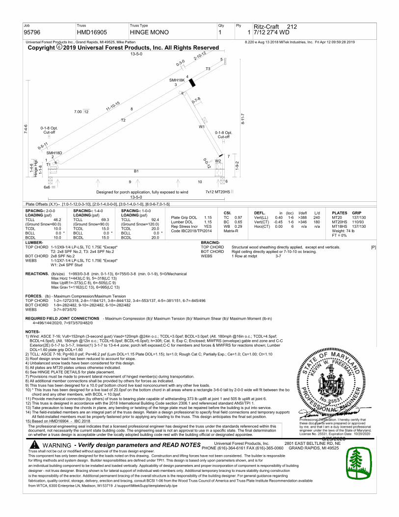
95796
Truss
HMD16905
Truss Type
HINGE MONO
Qty
1
Ply
1Ritz-Craft 2127/12 27'4 WD
8.220 e Aug 13 2018 MiTek Industries, Inc. Fri Apr 12 09:59:28 2019Universal Forest Products Inc., Grand Rapids, MI 49525, Mike Patten
T1
B1
W2
T2
T3
W1
12
3
4
6
7
8
5
9 10
6x6
SMH18D
7x12 MT20HS
SMH18K
0-7-8
0-3-0
11-10-15
0-5-11
1-4
-6H
inge H
gt.
7-4
-6
1-9
-2
2-10-12
0-1-8 Opt.Cut-off
0-1-8 Opt.Cut-off
0-0-12
13-5-0
13-5-0
1-1
-8
8-1
1-7
7.00 12
Plate Offsets (X,Y)-- [1:0-1-12,0-3-10], [2:0-1-4,0-0-0], [3:0-1-4,0-1-0], [6:0-6-7,0-1-5]
SPACING-: 2-0-0LOADING (psf)TCLL(Ground Snow=60.0)TCDLBCLLBCDL
46.2
10.00.0 *
10.0
SPACING-: 1-4-0LOADING (psf)TCLL(Ground Snow=90.0)TCDLBCLLBCDL
69.3
15.00.0 *
15.0
SPACING-: 1-0-0LOADING (psf)TCLL(Ground Snow=120.0)TCDLBCLLBCDL
92.4
20.00.0 *
20.0
Plate Grip DOLLumber DOLRep Stress IncrCode
1.151.15YES
IBC2018/TPI2014
CSI.
TCBCWBMatrix-R
0.970.650.29
DEFL.
Vert(LL)Vert(CT)Horz(CT)
in0.40
-0.450.00
(loc)1-61-6
6
l/defl>388>346
n/a
L/d240180n/a
PLATES
MT20MT20HSMT18HSWeight: 74 lbFT = 0%
GRIP
137/130110/93137/130
LUMBER-
TOP CHORD 1-1/2X9-1/4 LP-LSL TC 1.75E *Except*T2: 2x8 SPF No.2, T3: 2x4 SPF No.2
BOT CHORD 2x8 SPF No.2WEBS 1-1/2X7-1/4 LP-LSL TC 1.75E *Except*
W1: 2x4 SPF Stud
[P]
BRACING-
TOP CHORD Structural wood sheathing directly applied, except end verticals.BOT CHORD Rigid ceiling directly applied or 7-10-10 oc bracing.WEBS 1 Row at midpt 3-7
REACTIONS. (lb/size) 1=993/0-3-8 (min. 0-1-13), 6=755/0-3-8 (min. 0-1-9), 5=0/MechanicalMax Horz 1=443(LC 9), 5=-318(LC 13)Max Uplift1=-373(LC 8), 6=-505(LC 9)Max Grav1=1162(LC 13), 6=995(LC 13)
FORCES. (lb) - Maximum Compression/Maximum TensionTOP CHORD 1-2=-1272/318, 2-8=-1184/121, 3-8=-844/132, 3-4=-553/137, 4-5=-381/151, 6-7=-845/496BOT CHORD 1-9=-282/482, 9-10=-282/482, 6-10=-282/482WEBS 3-7=-973/570
REQUIRED FIELD JOINT CONNECTIONS - Maximum Compression (lb)/ Maximum Tension (lb)/ Maximum Shear (lb)/ Maximum Moment (lb-in)4=496/144/202/0, 7=973/570/482/0
NOTES-
1) Wind: ASCE 7-16; Vult=152mph (3-second gust) Vasd=120mph @24in o.c.; TCDL=3.0psf; BCDL=3.0psf; (Alt. 180mph @16in o.c.; TCDL=4.5psf;BCDL=4.5psf); (Alt. 180mph @12in o.c.; TCDL=6.0psf; BCDL=6.0psf); h=30ft; Cat. II; Exp C; Enclosed; MWFRS (envelope) gable end zone and C-CExterior(2E) 0-1-7 to 3-1-7, Interior(1) 3-1-7 to 13-4-4 zone; porch left exposed;C-C for members and forces & MWFRS for reactions shown; LumberDOL=1.60 plate grip DOL=1.60
2) TCLL: ASCE 7-16; Pg=60.0 psf; Ps=46.2 psf (Lum DOL=1.15 Plate DOL=1.15); Is=1.0; Rough Cat C; Partially Exp.; Ce=1.0; Cs=1.00; Ct=1.103) Roof design snow load has been reduced to account for slope.4) Unbalanced snow loads have been considered for this design.5) All plates are MT20 plates unless otherwise indicated.6) See HINGE PLATE DETAILS for plate placement.7) Provisions must be made to prevent lateral movement of hinged member(s) during transportation.8) All additional member connections shall be provided by others for forces as indicated.9) This truss has been designed for a 10.0 psf bottom chord live load nonconcurrent with any other live loads.10) * This truss has been designed for a live load of 20.0psf on the bottom chord in all areas where a rectangle 3-6-0 tall by 2-0-0 wide will fit between the bottom
chord and any other members, with BCDL = 10.0psf.11) Provide mechanical connection (by others) of truss to bearing plate capable of withstanding 373 lb uplift at joint 1 and 505 lb uplift at joint 6.12) This truss is designed in accordance with the 2018 International Building Code section 2306.1 and referenced standard ANSI/TPI 1.13) Take precaution to keep the chords in plane, any bending or twisting of the hinge plate must be repaired before the building is put into service.14) The field-installed members are an integral part of the truss design. Retain a design professional to specify final field connections and temporary supports.
All field-installed members must be properly fastened prior to applying any loading to the truss. This design anticipates the final set position.15) Based on HMD16904 - IBC 2018
- Verify design parameters and READ NOTES
an individual building component to be installed and loaded vertically. Applicability of design parameters and proper incorporation of component is responsibility of building
designer - not truss designer. Bracing shown is for lateral support of individual web members only. Additional temporary bracing to insure stability during construction
is the responsibility of the erector. Additional permanent bracing of the overall structure is the responsibility of the building designer. For general guidance regarding
fabrication, quality control, storage, delivery, erection and bracing, consult BCSI 1-06 from the Wood Truss Council of America and Truss Plate Institute Recommendation available
from WTCA, 6300 Enterprise LN, Madison, WI 53719 J:\support\MitekSupp\templates\ufp.tpe
WARNING
C
Universal Forest Products, Inc. 2801 EAST BELTLINE RD, NEPHONE (616)-364-6161 FAX (616)-365-0060 GRAND RAPIDS, MI 49525
This component has only been designed for the loads noted on this drawing. Construction and lifting forces have not been considered. The builder is responsible
for lifting methods and system design. Builder responsibilities are defined under TPI1. This design is based only upon parameters shown, and is for
The professional engineering seal indicates that a licensed professional engineer has designed the truss under the standards referenced within thisdocument, not necessarily the current state building code. The engineering seal is not an approval to use in a specific state. The final determinationon whether a truss design is acceptable under the locally adopted building code rest with the building official or designated appointee.
Truss shall not be cut or modified without approval of the truss design engineer.
Copyright 2019 Universal Forest Products, Inc. All Rights Reserved
Designed for porch application, fully exposed to wind
8/25/2020

95796 212 RITZ-CRAFT
Corporate Engineering 2801 East Beltline, NE Grand Rapids, MI 49525-9736 (616) 364-6161 Fax (616) 365-0060
ufpi.com
Job Truss MFG Customer
The professional engineering seal indicates that a licensed professional has reviewed the design under the standards referenced within this document, not necessarily the current state building code. The engineering seal is not an approval to use a design in a specific state. The final determination on whether a truss design is acceptable under the locally adopted building code rest with the building official or designated appointee.
HMD16905
Job
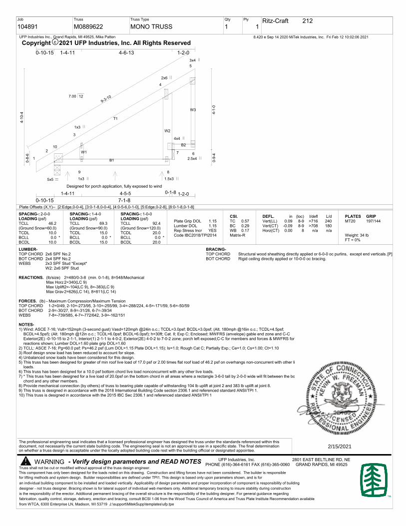
104891
Truss
M0889622
Truss Type
MONO TRUSS
Qty
1
Ply
1Ritz-Craft 212
8.420 e Sep 14 2020 MiTek Industries, Inc. Fri Feb 12 10:02:06 2021UFP Industries Inc., Grand Rapids, MI 49525, Mike Patten
B1
T1
W3
W2
B2
W1
1
2
3
4
5
9 8
7 6
10
5x5
3x4
2.5x4
2x6
4x4
1x3
1x3
1.5x3
9-3-10
1-4-11 4-5-5 0-1-8 1-2-0
0-10-15 7-1-8
0-10-15 1-4-11 4-6-13 1-2-0
0-8
-6
4-1
0-4 4
-1-0
0-9
-4
7.00 12
Plate Offsets (X,Y)-- [2:Edge,0-0-4], [3:0-1-8,0-0-4], [4:0-5-6,0-1-0], [5:Edge,0-2-8], [8:0-1-8,0-1-8]
SPACING-: 2-0-0LOADING (psf)TCLL(Ground Snow=60.0)TCDLBCLLBCDL
46.2
10.00.0 *
10.0
SPACING-: 1-4-0LOADING (psf)TCLL(Ground Snow=90.0)TCDLBCLLBCDL
69.3
15.00.0 *
15.0
SPACING-: 1-0-0LOADING (psf)TCLL(Ground Snow=120.0)TCDLBCLLBCDL
92.4
20.00.0 *
20.0
Plate Grip DOLLumber DOLRep Stress IncrCode
1.151.15YES
IBC2018/TPI2014
CSI.TCBCWBMatrix-R
0.570.290.17
DEFL.Vert(LL)Vert(CT)Horz(CT)
in0.09
-0.090.00
(loc)8-98-9
8
l/defl>716>708
n/a
L/d240180n/a
PLATESMT20
Weight: 34 lbFT = 0%
GRIP197/144
LUMBER-TOP CHORD 2x6 SPF No.2BOT CHORD 2x4 SPF No.2WEBS 2x3 SPF Stud *Except*
W2: 2x6 SPF Stud
[P]BRACING-TOP CHORD Structural wood sheathing directly applied or 6-0-0 oc purlins, except end verticals.BOT CHORD Rigid ceiling directly applied or 10-0-0 oc bracing.
REACTIONS. (lb/size) 2=480/0-3-8 (min. 0-1-8), 8=548/MechanicalMax Horz 2=340(LC 9)Max Uplift2=-104(LC 9), 8=-383(LC 9)Max Grav2=626(LC 14), 8=811(LC 14)
FORCES. (lb) - Maximum Compression/Maximum TensionTOP CHORD 1-2=0/49, 2-10=-273/95, 3-10=-255/99, 3-4=-288/224, 4-5=-171/59, 5-6=-50/59BOT CHORD 2-9=-30/27, 8-9=-31/26, 6-7=-39/34WEBS 7-8=-739/585, 4-7=-772/642, 3-9=-162/151
NOTES-1) Wind: ASCE 7-16; Vult=152mph (3-second gust) Vasd=120mph @24in o.c.; TCDL=3.0psf; BCDL=3.0psf; (Alt. 180mph @16in o.c.; TCDL=4.5psf;
BCDL=4.5psf); (Alt. 180mph @12in o.c.; TCDL=6.0psf; BCDL=6.0psf); h=30ft; Cat. II; Exp C; Enclosed; MWFRS (envelope) gable end zone and C-CExterior(2E) -0-10-15 to 2-1-1, Interior(1) 2-1-1 to 4-0-2, Exterior(2E) 4-0-2 to 7-0-2 zone; porch left exposed;C-C for members and forces & MWFRS forreactions shown; Lumber DOL=1.60 plate grip DOL=1.60
2) TCLL: ASCE 7-16; Pg=60.0 psf; Ps=46.2 psf (Lum DOL=1.15 Plate DOL=1.15); Is=1.0; Rough Cat C; Partially Exp.; Ce=1.0; Cs=1.00; Ct=1.103) Roof design snow load has been reduced to account for slope.4) Unbalanced snow loads have been considered for this design.5) This truss has been designed for greater of min roof live load of 17.0 psf or 2.00 times flat roof load of 46.2 psf on overhangs non-concurrent with other live
loads.6) This truss has been designed for a 10.0 psf bottom chord live load nonconcurrent with any other live loads.7) * This truss has been designed for a live load of 20.0psf on the bottom chord in all areas where a rectangle 3-6-0 tall by 2-0-0 wide will fit between the bottom
chord and any other members.8) Provide mechanical connection (by others) of truss to bearing plate capable of withstanding 104 lb uplift at joint 2 and 383 lb uplift at joint 8.9) This truss is designed in accordance with the 2018 International Building Code section 2306.1 and referenced standard ANSI/TPI 1.10) This truss is designed in accordance with the 2015 IBC Sec 2306.1 and referenced standard ANSI/TPI 1
- Verify design parameters and READ NOTES
an individual building component to be installed and loaded vertically. Applicability of design parameters and proper incorporation of component is responsibility of building
designer - not truss designer. Bracing shown is for lateral support of individual web members only. Additional temporary bracing to insure stability during construction
is the responsibility of the erector. Additional permanent bracing of the overall structure is the responsibility of the building designer. For general guidance regarding
fabrication, quality control, storage, delivery, erection and bracing, consult BCSI 1-06 from the Wood Truss Council of America and Truss Plate Institute Recommendation available
from WTCA, 6300 Enterprise LN, Madison, WI 53719 J:\support\MitekSupp\templates\ufp.tpe
WARNING
C
UFP Industries, Inc. 2801 EAST BELTLINE RD, NEPHONE (616)-364-6161 FAX (616)-365-0060 GRAND RAPIDS, MI 49525
This component has only been designed for the loads noted on this drawing. Construction and lifting forces have not been considered. The builder is responsible
for lifting methods and system design. Builder responsibilities are defined under TPI1. This design is based only upon parameters shown, and is for
The professional engineering seal indicates that a licensed professional engineer has designed the truss under the standards referenced within thisdocument, not necessarily the current state building code. The engineering seal is not an approval to use in a specific state. The final determinationon whether a truss design is acceptable under the locally adopted building code rest with the building official or designated appointee.
Truss shall not be cut or modified without approval of the truss design engineer.
Copyright 2021 UFP Industries, Inc. All Rights Reserved
Designed for porch application, fully exposed to wind
2/15/2021

104891 212 RITZ-CRAFT
Corporate Engineering 2801 East Beltline, NE Grand Rapids, MI 49525-9736 (616) 364-6161 Fax (616) 365-0060
ufpi.com
Job Truss MFG Customer
The professional engineering seal indicates that a licensed professional has reviewed the design under the standards referenced within this document, not necessarily the current state building code. The engineering seal is not an approval to use a design in a specific state. The final determination on whether a truss design is acceptable under the locally adopted building code rest with the building official or designated appointee.
M0889622

DATE: 10/15/2021 COMPANY: Ritz-Craft Corp PAVITRUVIUS BUILD: Base DESIGNED BY: Curt Zimmerman
CUSTOMER: REVIEWED BY: Curt ZimmermanPROJ. ADDRESS: -- PROJECT NAME: 2655921
--LEVEL: Main Floor LOADING: ASD
MEMBER NAME: HDR1 (W: TRUSS M0889622 ) CODE: 2018 International Building CodeMEMBER TYPE: FLOOR BEAM NDS: 2018 NDS
MATERIAL: Structural Composite LumberMurphy 2.0E LVL (3) 1.5 X 7.25 DRY
HDR1 (W: TRUSS M0889622 ) DIAGRAM
BEAM PROPERTIES
Area Ix Iy BSW Lams Cfn Kcr
(in²) (in⁴) (in⁴) (lbf/ft) Creep Factor
32.62 142.9 6.12 8.5 3 5.55 1
STRENGTH PROPERTIESFb (psi) Ft (psi) Fv (psi) Fc (psi) Fc⊥(psi) E (psi) x10³ Emin (psi) x10³
Base Values 3100 2100 290 3200 750 2000 984.984
Adjusted Values 3100 2100 290 3200 750 2000 985
CM 1 1 1 1 1 1 1
CT 1 1 1 1 1 1 1
Bending Adjustment Factors CV = 1.1 Cr = 1 Volume factor Is applied on a load combination basis And Is Not reflected in the adjusted values
BEAM DATAUnbraced Length (ft) Beam End
Span Length (ft) Top Bottom Elev. Diff (ft) CL(Top) CL(Bottom) CL(Left) CL(Right)
1 10.5 0 10.5 0 1.00 0.55 1.00 1.00
PASS-FAIL
Shear Stress Y (psi)
Bending Stress Y (psi)
Deflection (in)
Bearing Stress (psi)
PASS/FAIL
PASS (60.2%)PASS (40.9%)PASS (3.8%)
PASS (78.7%)
MAGNITUDE
115.5
2007.3
0.337 (=L/374)
159.5
STRENGTH
290.0
3394.6
0.350 (=L/360)
750.0
LOCATION (ft)
10.5
5.25
5.25
0
LOAD COMBO
D+L
D+L
L
D+L
DURATION FACTOR CD
1
1
1
REACTIONS Units for V: lbf Units for M: lbf-ft
DEAD LIVE LIVE ROOF SNOW WIND + WIND - SEISMIC + SEISMIC - ICE RAIN EARTHY axis
A 664 1848 0 0 0 0 0 0 0 0 0
B 664 1848 0 0 0 0 0 0 0 0 0
Reaction Location
A B
LOAD LIST
Uniform (lbf/ft) 352 352 0 10.5 Live Y
Uniform (lbf/ft) 118 118 0 10.5 Dead Y
Self Weight (lbf/ft) 8.5 8.5 0 10.5 Dead Y
Page 1
2018 International Building Code ASDPROJECT: 2655921
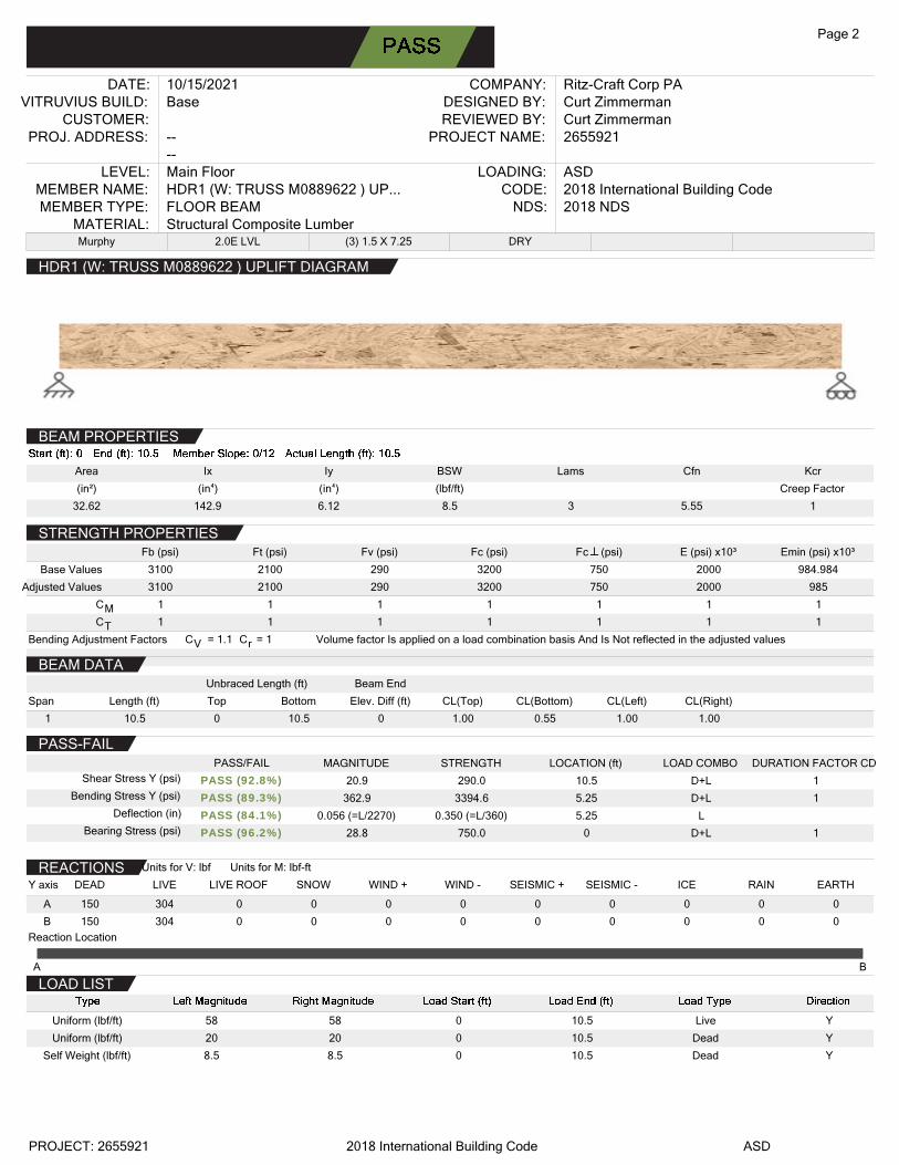
DATE: 10/15/2021 COMPANY: Ritz-Craft Corp PAVITRUVIUS BUILD: Base DESIGNED BY: Curt Zimmerman
CUSTOMER: REVIEWED BY: Curt ZimmermanPROJ. ADDRESS: -- PROJECT NAME: 2655921
--LEVEL: Main Floor LOADING: ASD
MEMBER NAME: HDR1 (W: TRUSS M0889622 ) UP... CODE: 2018 International Building CodeMEMBER TYPE: FLOOR BEAM NDS: 2018 NDS
MATERIAL: Structural Composite LumberMurphy 2.0E LVL (3) 1.5 X 7.25 DRY
HDR1 (W: TRUSS M0889622 ) UPLIFT DIAGRAM
BEAM PROPERTIES
Area Ix Iy BSW Lams Cfn Kcr
(in²) (in⁴) (in⁴) (lbf/ft) Creep Factor
32.62 142.9 6.12 8.5 3 5.55 1
STRENGTH PROPERTIESFb (psi) Ft (psi) Fv (psi) Fc (psi) Fc⊥(psi) E (psi) x10³ Emin (psi) x10³
Base Values 3100 2100 290 3200 750 2000 984.984
Adjusted Values 3100 2100 290 3200 750 2000 985
CM 1 1 1 1 1 1 1
CT 1 1 1 1 1 1 1
Bending Adjustment Factors CV = 1.1 Cr = 1 Volume factor Is applied on a load combination basis And Is Not reflected in the adjusted values
BEAM DATAUnbraced Length (ft) Beam End
Span Length (ft) Top Bottom Elev. Diff (ft) CL(Top) CL(Bottom) CL(Left) CL(Right)
1 10.5 0 10.5 0 1.00 0.55 1.00 1.00
PASS-FAIL
Shear Stress Y (psi)
Bending Stress Y (psi)
Deflection (in)
Bearing Stress (psi)
PASS/FAIL
PASS (92.8%)PASS (89.3%)PASS (84.1%)PASS (96.2%)
MAGNITUDE
20.9
362.9
0.056 (=L/2270)
28.8
STRENGTH
290.0
3394.6
0.350 (=L/360)
750.0
LOCATION (ft)
10.5
5.25
5.25
0
LOAD COMBO
D+L
D+L
L
D+L
DURATION FACTOR CD
1
1
1
REACTIONS Units for V: lbf Units for M: lbf-ft
DEAD LIVE LIVE ROOF SNOW WIND + WIND - SEISMIC + SEISMIC - ICE RAIN EARTHY axis
A 150 304 0 0 0 0 0 0 0 0 0
B 150 304 0 0 0 0 0 0 0 0 0
Reaction Location
A B
LOAD LIST
Uniform (lbf/ft) 58 58 0 10.5 Live Y
Uniform (lbf/ft) 20 20 0 10.5 Dead Y
Self Weight (lbf/ft) 8.5 8.5 0 10.5 Dead Y
Page 2
2018 International Building Code ASDPROJECT: 2655921

�������������� �� ��������������
����������������������
��� !"# $%&&'$()*+,-!#
./!�01)2�3!4 5678�9���:�";#<�/4 =�������>���?��@�A���B���CD���2�/-#�+"#<�/)E1F!4 ���G��H�������� !"#)E1F!4 A������C��?�����2�/3<#<�/!3)IJ���)K�!;47@8LM���5NJ;O</0)K�!; 75P
2J<Q;#!)R�/!4 M��SLTUU�BVVW�!�Q<#)X;#!4
2�/-#�+"#<�/)*<#!4(Y%)*K:Z*[\] )]_KXI]K a:Zb)c)de$e&
_f/!�gK0!/#4.h)*E:.)c_i.*$$)iZ:E_ )]_KX]_2c.*E.]b)c)dej%j%deee$d&Y&</k�l/!f-#1J!m�Q!-n"�Q
X!-<0/!�g2�/#�;"#��4]ZER)2]KIE)2_]�(&)ZX\*E]ZK:)�K]a)]_KXiZII:Z[\]Nb)�K)(ojYY&od'%%(d&e</k�l�<#Op"�;k#n"�Q
�!�Q<#)+Q,!�4
����������q�r�CC�C�?C��G�st������H���
TuLP�v������wD������� i;x<Q+Q)\K4576 �+�)\K4566
Em!)y)[!##!�)��)h��-!)Em;/)2�3!)Z/3!x)�!kJ!"#-))m�f)"J�-!)#�)"�QFJ<;/"!)#m!)m�+-!)<-),;-!3)�/)"�3!)#�;3!p�kk)�+J!-nZ#)X_.*)_E)F��z<3!);/)!-#<Q;#!)�k)!/!�01)+-!)��)"�-#)�!J;#<z!)#�);)Q</<Q+Qp"�3!)m�Q!n
2�QFJ<;/"!4
*J;,p�/p0�;3!)#�;3!�kk-);�!)/�)J�/0!�)"�/-<3!�!3)</)#m!)\K)��)F!�k��Q;/"!)"�QFJ<;/"!)F;#m)</)].*"m!"{n).;"m)-J;,p�/p0�;3!;--!Q,J1)</)#m!)-F!"<k<!3)"J<Q;#!)O�/!)Q+-#)Q!!#)#m!)Q</<Q+Q)!/!�01)"�3!)</-+J;#<�/)]pz;J+!);/3)3!F#m)�!|+<�!Q!/#-n
./z!J�F!)K--!Q,J<!-
tCC�������CC�t���
��r��������
��}��H~��?�
����uH~��?�
r���usH������
��usH������
r���ust
��ust
2!<J</04)IJ;#)2!<J</0)��)*"<--��)E�+-- (b&j% Y'nd dnd dnd$% dnd$% Y( Y(
h;JJ4)h��3)I�;Q!b)(%�)�n"n (be%% $(nd dnd dnd&o dndY& %% &$
X���4)*�J<3)X���)�+/3!�)&dy)0J;O</0� Y$ dn(Yd dne$d % (e
X���)(4)NJ;--)X���)��z!�)&dy)0J;O</0� Yd dn$'d dne$d ($ (e
h</3�f4)�</1J)I�;Q! ($$ dn$jd dne$d eY e'
IJ���4)KJJph��3)��<-#gE�+-- (b&j% ejnd dnd dnd$% dndee Y( &$
;Q!)p)E<#J! *<0/;#+�! X;#!
���������������������))Em!)F��F�-!3),+<J3</0)3!-<0/)3!-"�<,!3)m!�!)<-)"�/-<-#!/#)f<#m)#m!),+<J3</0)FJ;/-b)-F!"<k<";#<�/-b);/3)�#m!�";J"+J;#<�/-)-+,Q<##!3)f<#m)#m!)F!�Q<#);FFJ<";#<�/n)Em!)F��F�-!3),+<J3</0)m;-),!!/)3!-<0/!3)#�)Q!!#)#m!)$d(&)Z.22)�!|+<�!Q!/#-)</].*�����)�!�-<�/)4)].*"m!"{ph!,);/3)#�)"�QFJ1)f<#m)#m!)Q;/3;#��1)�!|+<�!Q!/#-)J<-#!3)</)#m!)].*�����)Z/-F!"#<�/)2m!"{J<-#n
��� !"#)E<#J!4)$%&&'$()*+,-!#
X;#;)k<J!/;Q!4 �;0!)()�k(
(dg(&g$(]!F��#)3;#!4
Matthew Jones
mjones
Typewritten text
MATTHEW JONES
mjones
Typewritten text
10/18/21

��������������� ���������� ����
����������������� ������
!"#$$%&�' �()�* �+���
$#$$, ��-�()�* �+���
./#$$0���)
12#$$3 ������4����5
66666667�8�-�)9�:��8��*����� *��;�8 �<=
(�����>�7��)������� ?@(3A�0�8��)
$#!/+��*�-
$#"17��)
@ ������>�3�������BC��;D �� B55�8� �8E
6666666@ ������?E�� D=FFFFFFFFFFFFFFFFFFFFFFFFF
66666663�������?E�� D=FFFFFFFFFFFFFFFFFFFFFFFFF
6666666+�� )�@ �� )=FFFFFFFFFFFFFFFFFFFFFFFFFFF
G�D = 7�� =
3�DD ���