Drafting RLL. SLC 500 Processor Operating Cycle Event in Operating Cycle Input Scan Program Scan...
40
Drafting RLL
-
Upload
clemence-allison -
Category
Documents
-
view
222 -
download
0
Transcript of Drafting RLL. SLC 500 Processor Operating Cycle Event in Operating Cycle Input Scan Program Scan...

Drafting RLL

SLC 500 Processor Operating Cycle

Event in Operating Cycle
• Input Scan
• Program Scan
• Output Scan
• Communications
• Processor Overhead

• The status of each input module is read, and the input image table in the processor is updated with the information.
• The ladder program is executed. The input image table is evaluated to see which conditions are met. Resulting information is written to the output table; however, no information is transferred to the output module until all rungs have been read. The output image table information is transferred to the output module affecting real-world outputs.
• Communications with computer and other network devices takes place.
• Internal housekeeping in the processor takes place, including updates of the status file and internal time base.
• Important:• Data concerning outputs is only written to the data table during
the program scan. Outputs are not actually updated until the output scan.

Ladder Logic
• Ladder Logic: User-programmed instructions designed to perform decision-making and computational functions based on data gathered from inputs.
• These user-programmed instructions rely on certain structural elements to organize the decision-making and computational processes. These organizational elements include:
• . Rungs• . Instructions• . Branches• Important:• Although ladder logic is based on electrical diagrams and symbols, it actually shows the
flow of logic.• Rungs• Ladder logic instructions are organized on rungs that order the steps• in the reading process, as seen in the following example:• .When placing rungs, keep these key points in mind:• . Rungs are scanned from zero to the highest number (top to• bottom).• . A rung is read from left to right.• . A new rung is automatically numbered according to where it is• placed.• . The last rung automatically contains an END instruction.

Ladder Logic

Drafting Ladder Logic

Drafting Ladder Logic for an RSLogix 500'" Project
• Instructions• Ladder logic may contain conditional input instructions and output• instructions as shown in the following example:• When programming instructions on a rung, keep these key points in
mind:• . A ladder logic rung is divided into two parts:• one or more conditional input instructions on the left that affect one
or more output instructions on the right.• . A rung may contain no inputs, but at minimum it must contain• one output.• . Because you are examining the state of an input (data) using
software, you can examine or compare the same piece of data multiple times in one program. The state of one input may affect several outputs.

Banches
• Branches are used in ladder logic to create different paths that direct the reading of the ladder logic conditional inputs and outputs as shown in the following example:


• When placing branches in ladder logic, keep these key points in mind:
• Branches are read from left to right, top to bottom.• A branch can be used to create a different path for reading inputs. • A branch can be used to program multiple outputs.• A branch must start and end on the same level.• A parallel branch has the same start and same end point as the branch it is below:• Parallel branches are evaluated faster than nested branches. The
number of parallel branches is limited by the processor memory.• A nested branch starts and ends inside the same branch.• Nested branches are limited to four


• Last Rung Rule• When programming an output on more than one
rung, be careful to• keep the following rule in mind:• Important:• Data concerning the state of an output is written
to the data table after rungs are evaluated. However, the actual outputs are not updated until the output scan. Because of this, the last state of the output in the data table will be the state of the output.

• Multiple Outputs
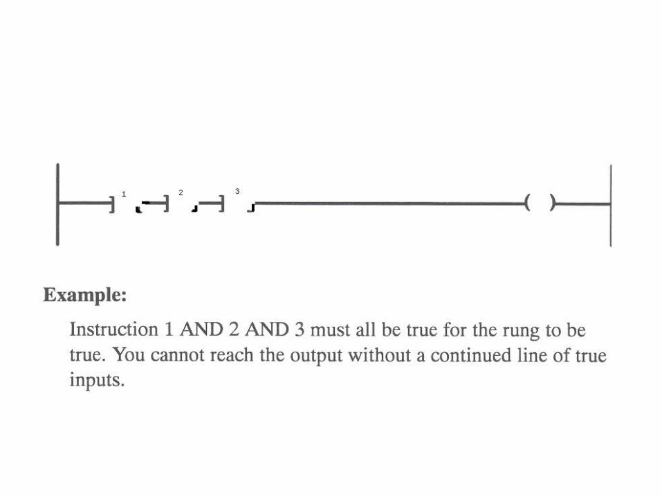
• If one condition determines one or more outputs, do not program
• them on separate rungs. Use parallel branches to program multiple outputs as shown in the following example:

Outputs that Require Separate Inputs:
• If outputs share common inputs, enter the common inputs once. Use
• a branch to place any additional condition(s):

• Example:• Both outputs require instruction A and B to be true;
however, the• path to output Y also requires instruction C to be true.

• Examination of an Output State
• The state of an output can be examined as a condition of the rung by
• using an input instruction with the output's address, as shown in the following example:

• Example:• When A and B are true, the rung is true. Once the rung is true, it• will remain true until condition B goes false and breaks the seal.• This type of seal-in logic is used often in programming. For example, if a
momentary push button is used to turn X on, X will remain on even if the operator releases the push button.

General Tips for Drafting Ladder Logic
• Ladder logic rarely goes directly from the programmer's head to the computer without causing rework. Try to write out your ladder logic first.

• With software you can examine inputs and condition several times. The state of an output can be a condition. The last state of an output is applied if an output is affected by more than one rung.
• Troubleshooting is much easier if ladder logic is well documented.

Examples
1. Conditions A or B or C or D, and E or F turn on output X.
2. Condition A and condition B, or state of output X, and condition B, turns on output X.
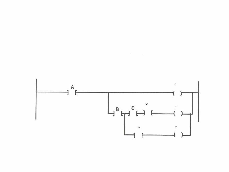
3. Condition A turns on output X. Conditions A and B and C and D turn on output Y. Conditions A and B, and E turn on output Z.
4. Conditions A and B and C, or D and B and C, or E and F, turn on output X.

Efficient Instruction Arrangement on Rungs and Branches
• Rule: When the processor encounters a false instruction on a rung, it
• stops scanning the rung and moves to the next rung of logic:
• For best performance: Sequence series instructions from the most likely to be false (at left) to least likely to be false (at right).

Efficient Arrangement of Multiple Branches
• Rule: As soon as the processor finds a true path, it will stop
• scanning and will not read any remaining branches:
• For best performance: If your rung contains parallel branches, place the path that is most often true on the top.

Examples
X = A(BC+D)E


X=Y=ABC

X =(AB+D)C

X=A+BCY=(A+BC)D

X=(A+B+C+D)(E+F)

X=(A+C)B