DRAFT TEST PROCEDURE
22
Preliminary Draft for Discussion Only -- Do Not Cite or Quote DRAFT TEST PROCEDURE Flash Emissions of Greenhouse Gases and Other Compounds from Crude Oil and Natural Gas Separator and Tank Systems Prepared By: Strategy Evaluation Section Alternative Fuels Branch Stationary Source Division California Air Resources Board March 2013 Revision
Transcript of DRAFT TEST PROCEDURE
Preliminary Draft for Discussion Only -- Do Not Cite or Quote
DRAFT TEST PROCEDURE
Flash Emissions of Greenhouse Gases and Other Compounds from Crude Oil and Natural Gas
Separator and Tank Systems
Prepared By: Strategy Evaluation Section
Alternative Fuels Branch Stationary Source Division
California Air Resources Board
March 2013 Revision
Preliminary Draft for Discussion Only -- Do Not Cite or Quote
1
California Environmental Protection Agency Air Resources Board
Draft Test Procedure
Flash Emissions of Greenhouse Gases and Other Compounds from Crude Oil and
Natural Gas Separator and Tank Systems 1. PURPOSE AND APPLICABILITY
This procedure is used to determine annual emission rates of Greenhouse Gases and other compounds from crude oil and natural gas separator and tank systems. This procedure is conducted by gathering one sample of crude oil or condensate and one sample of produced water from a pressurized vessel and having the liquids analyzed by a laboratory to determine the composition and volume of gas released from the liquids while they change from reservoir to standard atmospheric conditions. The laboratory results are used in conjunction with throughput to calculate the emission rates per year. Sampling and lab analyses may also be conducted to evaluate emissions from Flowback Fluids used to stimulate or hydraulically fracture a crude oil or natural gas well if they are handled by a separation and tank system. An alternative methodology is included for determining the specified emissions rates using measured vapor recovery system parameters provided the system meets the requirements specified in Section 9.
2. PRINCIPLE AND SUMMARY OF TEST PROCEDURE
The sampling and laboratory methods specified in this procedure are used to take samples of liquids and conduct a Flash Analysis on crude oil or natural gas separator and tank systems and are based on American Standards and Testing Materials (ASTM), US Environmental Protection Agency (EPA), and Gas Processor Association (GPA) methods and standards. The alternative vapor recovery system methodology described in Section 9 and 10.2 is based on common industry practices. Samples must be taken from a primary vessel located in a separator and tank system. Non-pressurized tanks or secondary vessels may not be used for sampling. Typical sampling points are from vessels used to measure Percent Water Cut (e.g., Automatic Well Tester) or vessels used for oil, water, and/or gas separation (e.g., Free Water Knockout). The liquids found in the primary vessels contain dissolved gases that will flash from the liquids as vapor when the liquids flow into lower pressure secondary vessels. This procedure is used to measure both the volume and composition of this flashed gas vapor. Liquid samples of a crude oil-produced water emulsion do not contain enough crude oil to be evaluated by a laboratory are not applicable to this procedure.
Preliminary Draft for Discussion Only -- Do Not Cite or Quote
2
Two sampling methods are specified: The first is a displacement method used for gathering crude oil or condensate. The second is for gathering produced water. Both methods are specified due to the nature of the laboratory analyses and the design of the sampling cylinders. Produced water cannot be displaced from a Double-Valve Cylinder using laboratory grade water and heavy crude oil may solidify and cause problems with a Floating-Piston Cylinder. The laboratory methods are used to measure the composition and volume of gas that flash from liquids while they cool or depressurize to standard atmospheric conditions. This includes the molecular weight and weight percent of the gaseous compounds and a Gas-Oil-Ratio or Gas-Water-Ratio. The laboratory results are applied to the annual liquid production rates to calculate Greenhouse Gas and other compound emission rates per year.
3. DEFINITIONS
For the purposes of this procedure, the following definitions apply:
3.1 "API Gravity" means a scale used to reflect the specific gravity (SG) of a fluid such as crude oil, water, or natural gas. The API gravity is calculated as [(141.5/SG) - 131.5], where SG is the specific gravity of the fluid at 60°F, and where API refers to the American Petroleum Institute.
3.2 “BTEX” means gaseous compounds of benzene, toluene, ethyl benzene,
and xylenes. 3.3 “Condensate” means hydrocarbon liquid, separated from crude oil or
natural gas, that condenses due to changes in temperature, pressure, or both, and which remains in liquid form under standard conditions.
3.4 “Crude Oil” means any of the naturally occurring liquids and semi-solids
found in rock formations composed of complex mixtures of hydrocarbon ranging from one to hundreds of carbon atoms in straight and branched chain rings.
3.5 “Double-Valve Cylinder” means a cylinder used for gathering crude oil or
condensate samples. The cylinder is provided by a laboratory filled with laboratory grade water which prevents flashing within the cylinder.
3.6 “Emulsion” means any mixture of crude oil, condensate, or produced
water in any proportion. 3.7 “Flashing” means the release of hydrocarbons and carbon dioxide from
liquid to surrounding air when the liquid changes temperature and pressure, also known as phase change.
Preliminary Draft for Discussion Only -- Do Not Cite or Quote
3
3.8 “Flash Analysis” means laboratory methodologies for measuring the volume and composition of gases released from liquids, including the molecular weight of the total gaseous sample, the weight percent of individual compounds, and a Gas-Oil Ratio or Gas-Water Ratio required to calculate the specified emission rates as described in Section 10.
3.9 “Flash Vapor” means the resulting quantity of hydrocarbon vapor and
carbon dioxide that is emitted from the liquid when the liquid changes temperature and pressure.
3.10 “Floating-Piston Cylinder” means a cylinder used for gathering produced
water. The cylinder contains an internal piston controlled by gas pressure. The piston prevents sample liquid from flashing within the sampling cylinder and provides a means of extracting the sample liquid.
3.11 “Flowback Fluid” means chemicals, fluids, or proppants injected
underground under pressure to stimulate or hydraulically fracture a crude oil or natural gas well or reservoir and that flows back to the surface as a fluid after injection is completed.
3.12 “Flowback Period” means the time it takes for an equivalent volume of
injected chemicals, fluids, or proppants injected into a crude oil or natural gas well to flow from the well and be processed by a tank system.
3.13 “Gas-Oil-Ratio (GOR)” means the ratio of gas produced from a barrel of
crude oil or condensate when cooling and depressurizing these liquids to standard conditions, expressed in terms of standard cubic feet of gas per barrel of oil.
3.14 “Gas-Water-Ratio (GWR)” means the ratio of gas produced from a barrel
of produced water when cooling and depressurizing produced water to standard conditions, expressed in terms of standard cubic feet of gas per barrel of water.
3.15 “Graduated Cylinder” means a measuring instrument for measuring fluid
volume, such as a glass container (cup or cylinder or flask) which has sides marked with or divided into amounts.
3.16 “Greenhouse Gases” means Carbon Dioxide and Methane for the
purposes of this Test Procedure.
3.17 “Operating Pressure” means the working pressure that characterizes the conditions of crude oil, condensate, or produced water inside a particular process, pipeline, vessel or tank. In general, low pressure liquid is under less than approximately 200 psig of pressure.
Preliminary Draft for Discussion Only -- Do Not Cite or Quote
4
3.18 “Operating Temperature” means the temperature that characterizes the conditions of crude oil, condensate, or produced water inside a particular process, pipeline, vessel or tank.
3.19 “Percent Water Cut” means the percentage of water by volume, of the
total emulsion throughput as measured using ASTM D-4007. The percent water cut is expressed as a percentage.
3.20 “Primary Vessel” means a separator or tank that receives crude oil,
condensate, produced water, natural gas, or emulsion from one or more crude oil, condensate, or natural gas wells or field gathering systems.
3.21 “Produced Water” means the resulting water that is produced as a
byproduct of crude oil or natural gas production. 3.22 “Reservoir” means a porous and permeable underground natural
formation containing crude oil or gas. A reservoir is characterized by a single natural pressure.
3.23 “Secondary Vessel” means a separator or tank that receives crude oil,
condensate, produced water, natural gas, or emulsion from one or more primary vessel separators or tanks.
3.24 “Separator” means a sump or vessel used to separate crude oil,
condensate, natural gas, produced water, emulsion, or solids. 3.25 “Sump” means a lined or unlined surface impoundment or depression in
the ground that, during normal operations, is used for separating crude oil, condensate, produced water, emulsion, or solids.
3.26 “Tank” means a container, constructed primarily of non-earthen materials,
used for holding or storing crude oil, condensate, produced water, or emulsion.
3.27 “Throughput” means the average volume of liquid processed by a vessel
over a period of time, such as barrels per day. The throughput of crude oil or condensate may need to be calculated using the Percent Water Cut. The throughput of crude oil or condensate is calculated as the difference between those liquids and the produced water.
3.28 “Vapor Recovery System” means equipment installed on vessels including
piping, connections, and if necessary, flow-inducing devices, designed to capture, control, or treat gaseous emissions, or for routing gas into a process as a product, as a fuel source, or for subsequent thermal destruction.
Preliminary Draft for Discussion Only -- Do Not Cite or Quote
5
3.29 “Vessel” means any container, constructed primarily of non-earthen materials, used to separate or store crude oil, condensate, natural gas, produced water, or emulsion.
3.30 “VOCC3-C9” means Volatile Organic Compounds with three to nine carbon
atoms. 3.31 “VOCC10+” means Volatile Organic Compounds with 10 or more carbon
atoms. This value is needed for laboratory and quality control purposes.
4. BIASES AND INTERFERENCES
4.1 The sampling methods specified in this procedure have an impact on the laboratory methods and the final results reported. All samples must be gathered in adherence with the minimum procedures and specifications identified in this procedure.
4.2 A representative sampling point must be selected to ensure that
pressurized gases remain suspended in liquid during sampling. Obtaining samples from a non-pressurized vessel or a vessel connected to a vapor recovery system will produce non-representative results.
4.3 All pressure and temperature measurements must be acquired using
calibrated instruments as described in Section 5. Un-calibrated equipment, including pressure or temperature gauges installed on vessels, may produce non-representative results. This may result in data errors when analyzing samples in a laboratory.
4.4 The analytical portion of this procedure must be conducted by laboratories
experienced with laboratory instrumentation, analytical methods, and the laboratory methods specified in this procedure.
5. EQUIPMENT SPECIFICATIONS
5.1 A pressure gauge capable of measuring liquid pressure less than 200
pounds per square inch pressure within +/-10% accuracy. 5.2 A pressure gauge capable of measuring liquid pressure greater than 200
pounds per square inch pressure within +/- 5% accuracy. 5.3 A temperature gauge capable of reading liquid temperature to within +/-
2oF. The range of the gauge must be at least 32 to 200oF. 5.4 A volume meter with a minimum of +/- 2% accuracy over the entire range
of flow rates for which the meter is used. Volume meters must be calibrated annually against a NIST traceable standard.
Preliminary Draft for Discussion Only -- Do Not Cite or Quote
6
6. TEST EQUIPMENT
6.1 A Double-Valve Cylinder filled with laboratory grade water for crude oil or condensate or a Floating-Piston Cylinder for produced water.
6.2 A Graduated Cylinder to measure displaced laboratory grade water from a
Double-Valve Cylinder. 6.3 A waste container suitable for capturing and disposing sample liquid. 6.4 High-pressure rated components and control valves that can withstand
pressure under the same operating conditions as the vessel sampled. 6.5 A low-pressure and a high-pressure measuring device with minimum
specifications listed in Section 5. 6.6 A temperature measuring device with minimum specifications listed in
Section 5. 6.7 A calibrated volume meter with temperature and pressure gauges each
with minimum specifications listed in Section 5 for measuring collected vapor recovery gas volume as described in Section 9.
6.8 A stainless steel hand pump equipped with one-way check valves suitable
for pumping low API gravity crude oil into a Double-Valve Cylinder per Section 7.3. Stainless steel is required to prevent sample contamination.
7. SAMPLING METHODS
Pre-Sampling Requirements
Prior to gathering liquid samples, the sampling technician must be provided with the vessel description, Throughput, Percent Water Cut, Days of Operation, and a description of the vapor recovery system on downstream vessels by the facility operator as indicated in Table 1 and on Form 1. This information is required to calculate and report the results of this test procedure. If required, the Percent Water Cut may be measured using ASTM D-4007. The results of this test procedure may be nullified without the specified information.
Background
The sampling method used for this procedure depends on the type of liquid to be sampled. Crude oil or condensate is collected using the Crude Oil or Condensate Sampling Method specified in Section 7.1. Produced water is collected using the Produced Water Sampling Method specified in Section 7.2. Low API gravity crude oil that will not flow into a sampling cylinder may be

Preliminary Draft for Discussion Only -- Do Not Cite or Quote
7
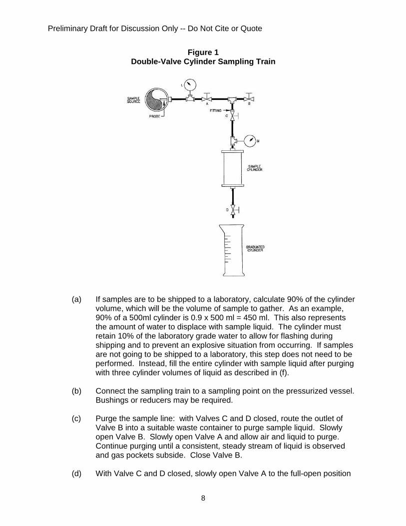
collected using the method specified in Section 7.3. Liquid samples must only be taken from separated liquids. This is accomplished by taking samples from different levels in a pressurized separator, which may be a permanent or temporarily installed vessel. Liquid samples of emulsions cannot be evaluated by a laboratory and are therefore not applicable to this procedure. To gather a liquid sample, the sample vessel must be pressurized. Samples must not be taken from tanks or separators open to atmosphere. When a liquid sample is gathered, the technician measures the pressure and temperature of the liquid using the calibrated gauges specified and records the vessel and liquid characteristics as reported by the facility operator. The cylinder is then identified with a Cylinder Identification Tag (See Section 8) and sent to a laboratory for analysis. The laboratory heats and pressurizes the liquid to the same conditions recorded at the time of sampling and performs a Flash Analysis which measures the rate and composition of gas evolved from the liquid while it cools and depressurizes to specified atmospheric conditions. 7.1 CRUDE OIL OR CONDENSATE SAMPLING METHOD The Crude Oil or Condensate Sampling Method is conducted by displacing laboratory grade water with pH between 5 and 7 from a Double-Valve Sampling Cylinder. Figure 1 illustrates a Double-Valve Cylinder sampling train. The configuration shows a cylinder outfitted with high-pressure rated components that can be used for controlling the flow of liquid. Calibrated temperature (Gauge L) and pressure (Gauge M) gauges are included for conducting field measurements. Sample liquid enters the cylinder when water is displaced into a graduated cylinder. The amount of sample liquid contained in the cylinder is equal to the amount of laboratory grade water measured in the graduated cylinder.
Preliminary Draft for Discussion Only -- Do Not Cite or Quote
8
Figure 1 Double-Valve Cylinder Sampling Train
(a) If samples are to be shipped to a laboratory, calculate 90% of the cylinder
volume, which will be the volume of sample to gather. As an example, 90% of a 500ml cylinder is 0.9 x 500 ml = 450 ml. This also represents the amount of water to displace with sample liquid. The cylinder must retain 10% of the laboratory grade water to allow for flashing during shipping and to prevent an explosive situation from occurring. If samples are not going to be shipped to a laboratory, this step does not need to be performed. Instead, fill the entire cylinder with sample liquid after purging with three cylinder volumes of liquid as described in (f).
(b) Connect the sampling train to a sampling point on the pressurized vessel.
Bushings or reducers may be required. (c) Purge the sample line: with Valves C and D closed, route the outlet of
Valve B into a suitable waste container to purge sample liquid. Slowly open Valve B. Slowly open Valve A and allow air and liquid to purge. Continue purging until a consistent, steady stream of liquid is observed and gas pockets subside. Close Valve B.
(d) With Valve C and D closed, slowly open Valve A to the full-open position
Preliminary Draft for Discussion Only -- Do Not Cite or Quote
9
and then slowly open Valve C to the full-open position. (e) Slowly open Valve D to allow a slow discharge of water into the graduated
cylinder at a rate of approximately 60 milliliters per minute (1 drip per second).
(f) Record the temperature from Gauge L and pressure from Gauge M while
the liquid is filling the cylinder. Do not take temperature or pressure measurements on stagnant liquid. If the sample is to be shipped as described in (a), continue displacing the laboratory grade water from the cylinder until 90% of the water is displaced. If the cylinder is not going to be shipped, continue filling the cylinder with sample liquid until three cylinder volumes of liquid have passed through the sampling cylinder.
(g) Close Valves D, C, and A in that order. (h) Purge the line pressure: slowly open Valve B and allow pressurized liquid
to drain into the waste container. (i) Disconnect the Double-Valve Cylinder from the sampling train and
disconnect the sampling train from the pressurized vessel. (j) Check Valves C and D for leaks. If either Valve C or D is leaking, drain
the cylinder into a suitable waste container and use a different cylinder to obtain a new sample.
(k) Wrap the threaded connections of the cylinder with Teflon tape and cap
using threaded metal caps to protect the threads and ensure the cylinder is securely sealed for shipping.
(l) Identify the sample cylinder as specified in Section 8. 7.2 PRODUCED WATER SAMPLING METHOD
The Produced Water Sampling Method is conducted using a Floating-Piston Cylinder. This allows the sample liquid to be extracted from the cylinder without using laboratory water. The cylinder is provided by a laboratory with the piston pressurized with inert gas to approximately 1,000 psig or greater. Note: produced water may be gathered using a Double-Valve Cylinder as described in Section 7.1 provided that the laboratory can displace the produced water from the cylinder without commingling the sample liquid with laboratory grade water. Prior to gathering a sample, the technician first measures the vessel pressure and temperature using the calibrated gauges specified. The technician then bleeds off excess pressure from the piston to at least 10
Preliminary Draft for Discussion Only -- Do Not Cite or Quote
10
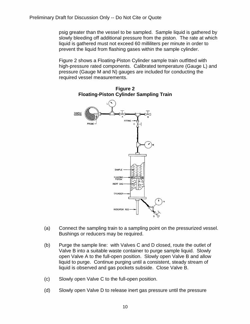
psig greater than the vessel to be sampled. Sample liquid is gathered by slowly bleeding off additional pressure from the piston. The rate at which liquid is gathered must not exceed 60 milliliters per minute in order to prevent the liquid from flashing gases within the sample cylinder. Figure 2 shows a Floating-Piston Cylinder sample train outfitted with high-pressure rated components. Calibrated temperature (Gauge L) and pressure (Gauge M and N) gauges are included for conducting the required vessel measurements.
Figure 2
Floating-Piston Cylinder Sampling Train
(a) Connect the sampling train to a sampling point on the pressurized vessel.
Bushings or reducers may be required.
(b) Purge the sample line: with Valves C and D closed, route the outlet of Valve B into a suitable waste container to purge sample liquid. Slowly open Valve A to the full-open position. Slowly open Valve B and allow liquid to purge. Continue purging until a consistent, steady stream of liquid is observed and gas pockets subside. Close Valve B.
(c) Slowly open Valve C to the full-open position. (d) Slowly open Valve D to release inert gas pressure until the pressure
Preliminary Draft for Discussion Only -- Do Not Cite or Quote
11
indicated on Gauge N is equal to Gauge M. When both gauges read equal pressure, close Valve D and prepare to gather sample liquid.
(e) Slowly open Valve D and allow liquid to enter the cylinder at a slow rate of
approximately 60 ml per minute to prevent liquid from flashing within the sampling cylinder. Use the measurement scale located on the sampling cylinder and a stopwatch to measure the rate at which liquid is gathered.
(f) Record the temperature from Gauge L and pressure from Gauge M while
liquid is gathered. Do not take measurements on stagnant liquid. (g) Continue gathering liquid until the cylinder is 80% full as indicated on the
cylinder scale. The rate at which liquid enters the cylinder, and the volume of liquid in the cylinder, are indicated on the sample cylinder. No outage is required when using a Floating-Piston Cylinder.
(h) Close valves D, C, and A in that order. (i) Purge the line pressure: slowly open Valve B and allow pressurized liquid
to drain into the waste container. (j) Disconnect the Floating-Piston Cylinder from the sampling train and
disconnect the sampling train from the pressurized vessel. (k) Check Valves C and D for leaks. If either Valve C or D is leaking, drain
the cylinder into a suitable waste container and use a different cylinder to obtain a new sample.
(l) Wrap the threaded connections of the cylinder with Teflon tape and cap
using threaded metal caps to protect the threads and ensure the cylinder is securely sealed for shipping.
(m) Identify the sample cylinder as specified in Section 8. 7.3 LOW API GRAVITY CRUDE OIL SAMPLING METHOD
In some cases, low API gravity crude oil may not flow into a sampling cylinder. This could be due to the viscosity, temperature, or pressure of the oil. In these cases, a stainless steel hand pump is used to assist with the collection of liquid. The pump must be outfitted with one-way check valves to ensure that liquid flows in only one direction. The difference between the Displacement Method and this method is that the hand pump is used in place of system pressure. (a) Install the stainless steel hand pump equipped with one-way check valves
as described in Section 6 at the inlet of the Double-Valve Cylinder Sampling Train.
Preliminary Draft for Discussion Only -- Do Not Cite or Quote
12
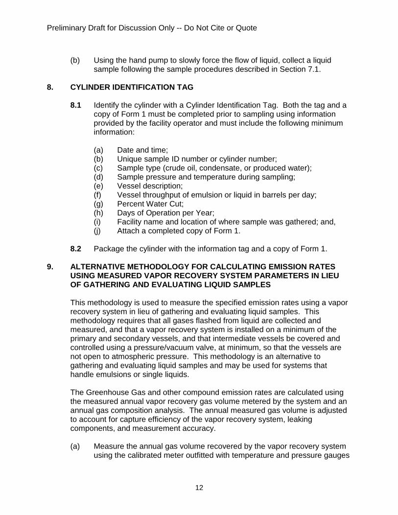
(b) Using the hand pump to slowly force the flow of liquid, collect a liquid
sample following the sample procedures described in Section 7.1.
8. CYLINDER IDENTIFICATION TAG 8.1 Identify the cylinder with a Cylinder Identification Tag. Both the tag and a
copy of Form 1 must be completed prior to sampling using information provided by the facility operator and must include the following minimum information:
(a) Date and time; (b) Unique sample ID number or cylinder number; (c) Sample type (crude oil, condensate, or produced water); (d) Sample pressure and temperature during sampling; (e) Vessel description; (f) Vessel throughput of emulsion or liquid in barrels per day; (g) Percent Water Cut; (h) Days of Operation per Year; (i) Facility name and location of where sample was gathered; and, (j) Attach a completed copy of Form 1.
8.2 Package the cylinder with the information tag and a copy of Form 1.
9. ALTERNATIVE METHODOLOGY FOR CALCULATING EMISSION RATES
USING MEASURED VAPOR RECOVERY SYSTEM PARAMETERS IN LIEU OF GATHERING AND EVALUATING LIQUID SAMPLES
This methodology is used to measure the specified emission rates using a vapor recovery system in lieu of gathering and evaluating liquid samples. This methodology requires that all gases flashed from liquid are collected and measured, and that a vapor recovery system is installed on a minimum of the primary and secondary vessels, and that intermediate vessels be covered and controlled using a pressure/vacuum valve, at minimum, so that the vessels are not open to atmospheric pressure. This methodology is an alternative to gathering and evaluating liquid samples and may be used for systems that handle emulsions or single liquids. The Greenhouse Gas and other compound emission rates are calculated using the measured annual vapor recovery gas volume metered by the system and an annual gas composition analysis. The annual measured gas volume is adjusted to account for capture efficiency of the vapor recovery system, leaking components, and measurement accuracy. (a) Measure the annual gas volume recovered by the vapor recovery system
using the calibrated meter outfitted with temperature and pressure gauges
Preliminary Draft for Discussion Only -- Do Not Cite or Quote
13
as described in Section 6.
(b) Obtain an annual gas sample of the vapor recovery gas and evaluate it for all gaseous compounds, the molecular weight, and the weight percent of Greenhouse Gases and other compounds.
(c) Calculate the annual emission rates as described in Section 10.2.
10. CALCULATING RESULTS
10.1 Flash Emission Calculation Methodology for Liquid Samples The following is used in conjunction with vessel information and a laboratory analysis to calculate metric tons of Greenhouse Gases (CO2 and CH4) or short tons of other compounds (VOCC3-C9 or BTEX). The same formulas may be applied to crude oil, condensate, and produced water. (a) If required, calculate the barrels per day of crude oil or condensate in
emulsion using the Percent Water Cut:
( )( )ThroughputCutWaterPercentDayBarrels −= 1/ Equation 1A
Where: Barrels/Day = barrels per day crude oil or condensate
Percent Water Cut = percentage of produced water in emulsion Throughput = barrels per day of emulsion
(b) If required, calculate the barrels per day of produced water in emulsion using the Percent Water Cut:
( )( )ThroughputCutWaterPercentDayBarrels =/ Equation 1B
Where:
Barrels/Day = barrels per day produced water Percent Water Cut = percentage of produced water in emulsion Throughput = barrels per day of emulsion
(c) Calculate the total volume of gas produced per year:
( )
=
YearDays
DayBarrelsGYearFt /3 Equation 2
Where: Ft3/Year = standard cubic feet of gas produced per year G = Gas-Oil-Ratio or Gas-Water-Ratio (from lab analysis)
Preliminary Draft for Discussion Only -- Do Not Cite or Quote
14
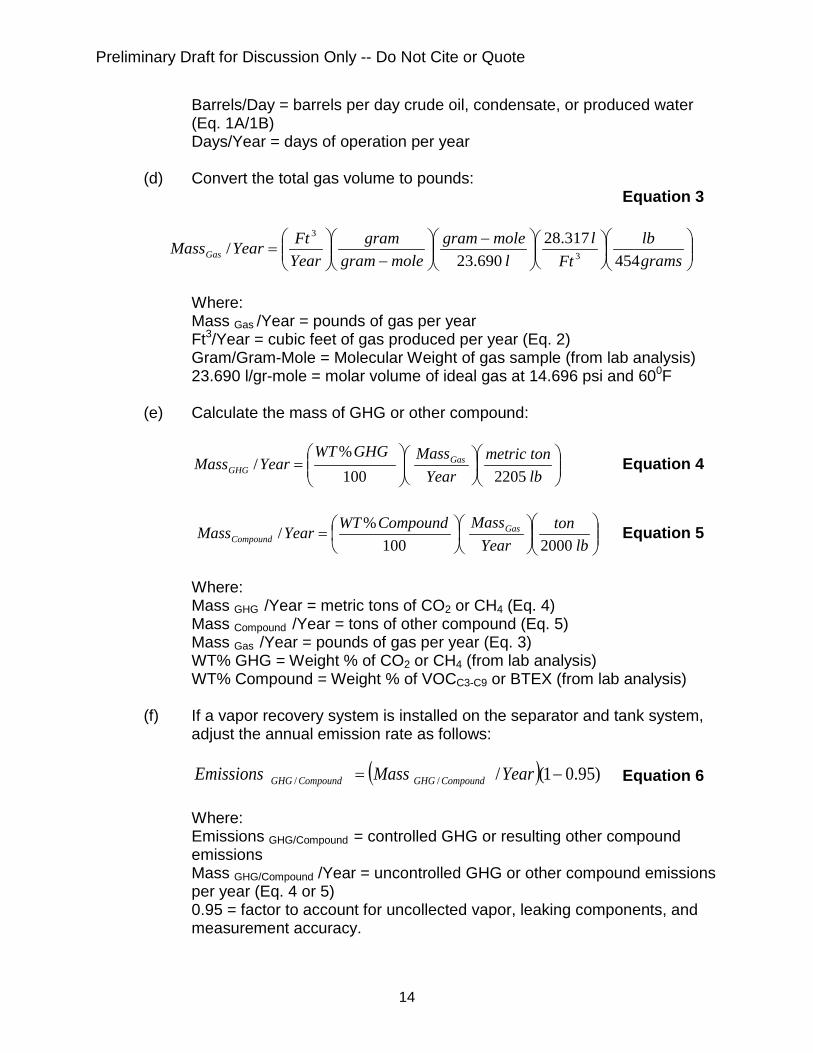
Barrels/Day = barrels per day crude oil, condensate, or produced water (Eq. 1A/1B)
Days/Year = days of operation per year (d) Convert the total gas volume to pounds:
Equation 3
−
−
=
gramslb
Ftl
lmolegram
molegramgram
YearFtYearMassGas 454
317.28690.23
/ 3
3
Where:
Mass Gas /Year = pounds of gas per year Ft3/Year = cubic feet of gas produced per year (Eq. 2) Gram/Gram-Mole = Molecular Weight of gas sample (from lab analysis) 23.690 l/gr-mole = molar volume of ideal gas at 14.696 psi and 600F
(e) Calculate the mass of GHG or other compound:
=
lbtonmetric
YearMassGHGWT
YearMass GasGHG 2205100
%/ Equation 4
=
lbton
YearMassCompoundWTYearMass Gas
Compound 2000100%/ Equation 5
Where: Mass GHG /Year = metric tons of CO2 or CH4 (Eq. 4) Mass Compound /Year = tons of other compound (Eq. 5) Mass Gas /Year = pounds of gas per year (Eq. 3) WT% GHG = Weight % of CO2 or CH4 (from lab analysis) WT% Compound = Weight % of VOCC3-C9 or BTEX (from lab analysis)
(f) If a vapor recovery system is installed on the separator and tank system, adjust the annual emission rate as follows:
( ) )95.01(/// −= YearMassEmissions CompoundGHGCompoundGHG Equation 6
Where:
Emissions GHG/Compound = controlled GHG or resulting other compound emissions Mass GHG/Compound /Year = uncontrolled GHG or other compound emissions per year (Eq. 4 or 5) 0.95 = factor to account for uncollected vapor, leaking components, and measurement accuracy.
Preliminary Draft for Discussion Only -- Do Not Cite or Quote
15
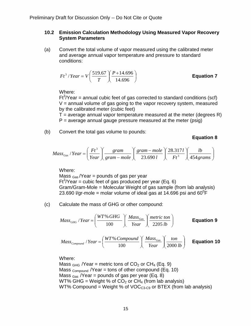
10.2 Emission Calculation Methodology Using Measured Vapor Recovery System Parameters
(a) Convert the total volume of vapor measured using the calibrated meter
and average annual vapor temperature and pressure to standard conditions:
+
=
696.14696.1467.519/3 P
TVYearFt Equation 7
Where:
Ft3/Year = annual cubic feet of gas corrected to standard conditions (scf) V = annual volume of gas going to the vapor recovery system, measured by the calibrated meter (cubic feet) T = average annual vapor temperature measured at the meter (degrees R) P = average annual gauge pressure measured at the meter (psig)
(b) Convert the total gas volume to pounds:
Equation 8
−
−
=
gramslb
Ftl
lmolegram
molegramgram
YearFtYearMassGas 454
317.28690.23
/ 3
3
Where:
Mass Gas /Year = pounds of gas per year Ft3/Year = cubic feet of gas produced per year (Eq. 6) Gram/Gram-Mole = Molecular Weight of gas sample (from lab analysis) 23.690 l/gr-mole = molar volume of ideal gas at 14.696 psi and 600F
(c) Calculate the mass of GHG or other compound:
=
lbtonmetric
YearMassGHGWT
YearMass GasGHG 2205100
%/ Equation 9
=
lbton
YearMassCompoundWTYearMass Gas
Compound 2000100%/ Equation 10
Where: Mass GHG /Year = metric tons of CO2 or CH4 (Eq. 9) Mass Compound /Year = tons of other compound (Eq. 10) Mass Gas /Year = pounds of gas per year (Eq. 8) WT% GHG = Weight % of CO2 or CH4 (from lab analysis) WT% Compound = Weight % of VOCC3-C9 or BTEX (from lab analysis)
Preliminary Draft for Discussion Only -- Do Not Cite or Quote
16
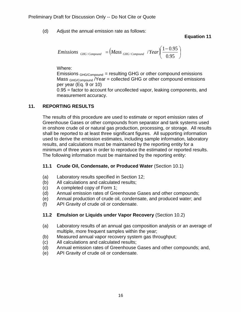
(d) Adjust the annual emission rate as follows: Equation 11
( )
−
=95.0
95.01/// YearMassEmissions CompoundGHGCompoundGHG
Where:
Emissions GHG/Compound = resulting GHG or other compound emissions Mass GHG/Compound /Year = collected GHG or other compound emissions per year (Eq. 9 or 10) 0.95 = factor to account for uncollected vapor, leaking components, and measurement accuracy.
11. REPORTING RESULTS
The results of this procedure are used to estimate or report emission rates of Greenhouse Gases or other compounds from separator and tank systems used in onshore crude oil or natural gas production, processing, or storage. All results shall be reported to at least three significant figures. All supporting information used to derive the emission estimates, including sample information, laboratory results, and calculations must be maintained by the reporting entity for a minimum of three years in order to reproduce the estimated or reported results. The following information must be maintained by the reporting entity:
11.1 Crude Oil, Condensate, or Produced Water (Section 10.1) (a) Laboratory results specified in Section 12; (b) All calculations and calculated results; (c) A completed copy of Form 1; (d) Annual emission rates of Greenhouse Gases and other compounds; (e) Annual production of crude oil, condensate, and produced water; and (f) API Gravity of crude oil or condensate.
11.2 Emulsion or Liquids under Vapor Recovery (Section 10.2)
(a) Laboratory results of an annual gas composition analysis or an average of
multiple, more frequent samples within the year; (b) Measured annual vapor recovery system gas throughput; (c) All calculations and calculated results; (d) Annual emission rates of Greenhouse Gases and other compounds; and, (e) API Gravity of crude oil or condensate.
Preliminary Draft for Discussion Only -- Do Not Cite or Quote
17
12. ANALYTICAL LABORATORY METHODS
12.1 Laboratory Methods
The following methods are required to evaluate and report flash emission rates from crude oil, condensate, and produced water. All methods and quality control requirements shall be conducted as specified in each method.
(a) Hydrogen Sulfide (Low-Level): Evaluate using EPA Method 15 and EPA
Method 16 or use ASTM D-1945M (Thermal Conductivity Detector), ASTM D-5504 (sulfur chemiluminescence detector), and ASTM D-6228 (flame photometric detector) as alternate methods.
(b) Oxygen, Nitrogen, Carbon Dioxide, Hydrogen Sulfide (High-Level), Methane, Ethane, Propane, i-Butane, n-Butane, i-Pentane, n-Pentane, Hexanes, Heptanes, Octanes, Nonanes, Decanes+: Evaluate per ASTM D-1945, ASTM D-3588, and ASTM D-2597 (GC/TCD). Note: This analysis requires all three methods specified. The base method is ASTM D-1945, which is modified to extend the hydrocarbon analysis range based on information from the other two methods.
(c) BTEX: Evaluate per EPA 8021 B (GC/FID) or use ASTM D-3170, GPA
2286, EPA 8260B, EPA TO-14, and EPA TO-15 as alternate methods. (d) API Gravity of liquid phase crude oil or condensate at 60 degrees
Fahrenheit (60oF): Evaluate per ASTM D-287 using measured result of Specific Gravity. Note: If water is entrained in the sample, measure the API Gravity using ASTM D-287 (API Hydrometer) and calculate the Specific Gravity using the measured API Gravity.
(e) Specific Gravity of pre-flash liquid phase crude oil or condensate:
Evaluate per ASTM D-4052, ASTM D-70, or ASTM D-5002 or calculate using results from ASTM D-287.
(f) Molecular Weight of gaseous phase by calculation per ASTM D-3588.
(g) Percent Water Cut: evaluate per ASTM D-4007 (Basic Sediment and
Water). 12.2 Laboratory Reports
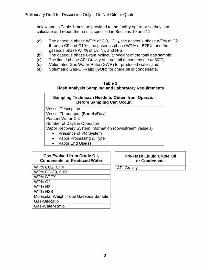
Any chromatograph system that allows for the collection, storage, interpretation, adjustment, or quantification of chromatograph detector output signals representing relative component concentrations may be used to conduct this procedure. The laboratory results must be reported as specified in Section 11. A laboratory report that provides the following minimum information described
Preliminary Draft for Discussion Only -- Do Not Cite or Quote
18
below and in Table 1 must be provided to the facility operator so they can calculate and report the results specified in Sections 10 and 11:
(a) The gaseous phase WT% of CO2, CH4, the gaseous phase WT% of C2
through C9 and C10+, the gaseous phase WT% of BTEX, and the gaseous phase WT% of O2, N2, and H2S;
(b) The gaseous phase Gram Molecular Weight of the total gas sample; (c) The liquid phase API Gravity of crude oil or condensate at 60oF; (d) Volumetric Gas-Water-Ratio (GWR) for produced water; and, (e) Volumetric Gas-Oil-Ratio (GOR) for crude oil or condensate.
Table 1
Flash Analysis Sampling and Laboratory Requirements
Gas Evolved from Crude Oil, Condensate, or Produced Water
WT% CO2, CH4 WT% C2-C9, C10+ WT% BTEX WT% O2 WT% N2 WT% H2S Molecular Weight Total Gaseous Sample Gas-Oil-Ratio Gas-Water-Ratio
Sampling Technician Needs to Obtain from Operator Before Sampling Can Occur:
Vessel Description Vessel Throughput (Barrels/Day) Percent Water Cut Number of Days in Operation Vapor Recovery System Information (downstream vessels)
• Presence of VR System • Vapor Processing & Type • Vapor End Use(s)
Pre-Flash Liquid Crude Oil or Condensate
API Gravity
Preliminary Draft for Discussion Only -- Do Not Cite or Quote
19
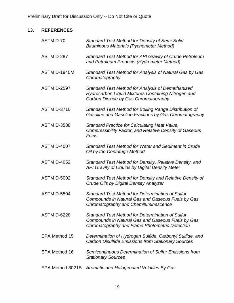
13. REFERENCES ASTM D-70 Standard Test Method for Density of Semi-Solid
Bituminous Materials (Pycnometer Method) ASTM D-287 Standard Test Method for API Gravity of Crude Petroleum
and Petroleum Products (Hydrometer Method) ASTM D-1945M Standard Test Method for Analysis of Natural Gas by Gas
Chromatography ASTM D-2597 Standard Test Method for Analysis of Demethanized
Hydrocarbon Liquid Mixtures Containing Nitrogen and Carbon Dioxide by Gas Chromatography
ASTM D-3710 Standard Test Method for Boiling Range Distribution of
Gasoline and Gasoline Fractions by Gas Chromatography ASTM D-3588 Standard Practice for Calculating Heat Value,
Compressibility Factor, and Relative Density of Gaseous Fuels
ASTM D-4007 Standard Test Method for Water and Sediment in Crude
Oil by the Centrifuge Method ASTM D-4052 Standard Test Method for Density, Relative Density, and
API Gravity of Liquids by Digital Density Meter ASTM D-5002 Standard Test Method for Density and Relative Density of
Crude Oils by Digital Density Analyzer ASTM D-5504 Standard Test Method for Determination of Sulfur
Compounds in Natural Gas and Gaseous Fuels by Gas Chromatography and Chemiluminescence
ASTM D-6228 Standard Test Method for Determination of Sulfur
Compounds in Natural Gas and Gaseous Fuels by Gas Chromatography and Flame Photometric Detection
EPA Method 15 Determination of Hydrogen Sulfide, Carbonyl Sulfide, and
Carbon Disulfide Emissions from Stationary Sources EPA Method 16 Semicontinuous Determination of Sulfur Emissions from
Stationary Sources EPA Method 8021B Aromatic and Halogenated Volatiles By Gas
Preliminary Draft for Discussion Only -- Do Not Cite or Quote
20
Chromatography Using Photoionization And/Or Electrolytic Conductivity Detectors
EPA Method 8260B Volatile Organic Compounds By Gas
Chromatography/Mass Spectrometry (GC/MS) EPA Method TO-14 Determination Of Volatile Organic Compounds (VOCs) In
Ambient Air Using Specially Prepared Canisters With Subsequent Analysis By Gas Chromatography
EPA Method TO-15 Determination Of Volatile Organic Compounds (VOCs) In
Air Collected In Specially-Prepared Canisters And Analyzed By Gas Chromatography/Mass Spectrometry (GC/MS)
GPA 2286 Extended Gas Analysis Utilizing a Flame Ionization
Detector
Preliminary Draft for Discussion Only -- Do Not Cite or Quote
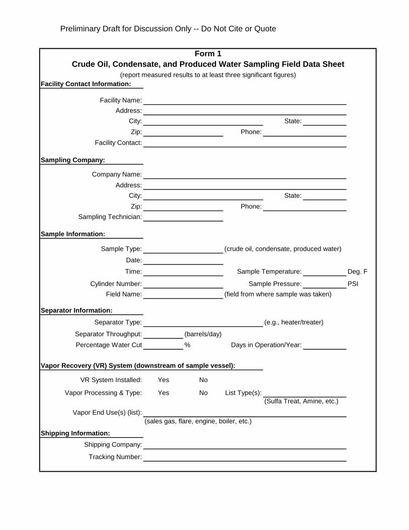
Facility Contact Information:
Facility Name:Address:
City: State:Zip: Phone:
Facility Contact:
Sampling Company:
Company Name:Address:
City: State:Zip: Phone:
Sampling Technician:
Sample Information:
Sample Type: (crude oil, condensate, produced water)
Date:
Time: Sample Temperature: Deg. F
Cylinder Number: Sample Pressure: PSIField Name: (field from where sample was taken)
Separator Information:
Separator Type: (e.g., heater/treater)
Separator Throughput: (barrels/day)Percentage Water Cut % Days in Operation/Year:
Vapor Recovery (VR) System (downstream of sample vessel):
VR System Installed: Yes No
Vapor Processing & Type: Yes No List Type(s):(Sulfa Treat, Amine, etc.)
Vapor End Use(s) (list):(sales gas, flare, engine, boiler, etc.)
Shipping Information:Shipping Company:
Tracking Number:
Crude Oil, Condensate, and Produced Water Sampling Field Data SheetForm 1
(report measured results to at least three significant figures)