Draft ETSI EN 302 372 V2.1€¦ · Draft ETSI EN 302 372 V2.1.0 (2016-04) Short Range Devices...
85
Draft ETSI EN 302 372 V2.1.0 (2016-04) Short Range Devices (SRD); Tank Level Probing Radar (TLPR) equipment operating in the frequency ranges 4,5 GHz to 7 GHz, 8,5 GHz to 10,6 GHz, 24,05 GHz to 27 GHz, 57 GHz to 64 GHz, 75 GHz to 85 GHz; Harmonised Standard covering the essential requirements of article 3.2 of the Directive 2014/53/EU HARMONISED EUROPEAN STANDARD
Transcript of Draft ETSI EN 302 372 V2.1€¦ · Draft ETSI EN 302 372 V2.1.0 (2016-04) Short Range Devices...

Draft ETSI EN 302 372 V2.1.0 (2016-04)
Short Range Devices (SRD); Tank Level Probing Radar (TLPR) equipment operating in the
frequency ranges 4,5 GHz to 7 GHz, 8,5 GHz to 10,6 GHz, 24,05 GHz to 27 GHz, 57 GHz to 64 GHz, 75 GHz to 85 GHz; Harmonised Standard covering the essential requirements
of article 3.2 of the Directive 2014/53/EU
HARMONISED EUROPEAN STANDARD
ETSI
Draft ETSI EN 302 372 V2.1.0 (2016-04) 2
Reference REN/ERM-TGUWB-131
Keywords EHF, harmonised standard, radar, regulation,
SHF, short range, SRD, testing, UWB
ETSI
650 Route des Lucioles F-06921 Sophia Antipolis Cedex - FRANCE
Tel.: +33 4 92 94 42 00 Fax: +33 4 93 65 47 16
Siret N° 348 623 562 00017 - NAF 742 C
Association à but non lucratif enregistrée à la Sous-Préfecture de Grasse (06) N° 7803/88
Important notice
The present document can be downloaded from: http://www.etsi.org/standards-search
The present document may be made available in electronic versions and/or in print. The content of any electronic and/or print versions of the present document shall not be modified without the prior written authorization of ETSI. In case of any
existing or perceived difference in contents between such versions and/or in print, the only prevailing document is the print of the Portable Document Format (PDF) version kept on a specific network drive within ETSI Secretariat.
Users of the present document should be aware that the document may be subject to revision or change of status. Information on the current status of this and other ETSI documents is available at
https://portal.etsi.org/TB/ETSIDeliverableStatus.aspx
If you find errors in the present document, please send your comment to one of the following services: https://portal.etsi.org/People/CommiteeSupportStaff.aspx
Copyright Notification
No part may be reproduced or utilized in any form or by any means, electronic or mechanical, including photocopying and microfilm except as authorized by written permission of ETSI.
The content of the PDF version shall not be modified without the written authorization of ETSI. The copyright and the foregoing restriction extend to reproduction in all media.
© European Telecommunications Standards Institute 2016.
All rights reserved.
DECTTM, PLUGTESTSTM, UMTSTM and the ETSI logo are Trade Marks of ETSI registered for the benefit of its Members. 3GPPTM and LTE™ are Trade Marks of ETSI registered for the benefit of its Members and
of the 3GPP Organizational Partners. GSM® and the GSM logo are Trade Marks registered and owned by the GSM Association.

ETSI
Draft ETSI EN 302 372 V2.1.0 (2016-04) 3
Contents
Intellectual Property Rights ................................................................................................................................ 8
Foreword ............................................................................................................................................................. 8
Modal verbs terminology .................................................................................................................................... 8
Introduction ........................................................................................................................................................ 8
1 Scope ...................................................................................................................................................... 10
2 References .............................................................................................................................................. 11
2.1 Normative references ....................................................................................................................................... 11
2.2 Informative references ...................................................................................................................................... 11
3 Definitions, symbols and abbreviations ................................................................................................. 12
3.1 Definitions ........................................................................................................................................................ 12
3.2 Symbols ............................................................................................................................................................ 13
3.3 Abbreviations ................................................................................................................................................... 14
4 Technical requirements specifications ................................................................................................... 15
4.1 Environmental conditions ................................................................................................................................. 15
4.2 General ............................................................................................................................................................. 15
4.3 Transmitter conformance requirements ............................................................................................................ 15
4.3.1 Permitted frequency range of operation ...................................................................................................... 15
4.3.1.1 Applicability.......................................................................................................................................... 15
4.3.1.2 Description ............................................................................................................................................ 15
4.3.1.3 Limits .................................................................................................................................................... 15
4.3.1.4 Conformance ......................................................................................................................................... 16
4.3.2 Operating bandwidth................................................................................................................................... 16
4.3.2.1 Applicability.......................................................................................................................................... 16
4.3.2.2 Description ............................................................................................................................................ 16
4.3.2.3 Limits .................................................................................................................................................... 16
4.3.2.4 Conformance ......................................................................................................................................... 16
4.3.3 Maximum value of mean power spectral density ....................................................................................... 17
4.3.4 Maximum value of peak power .................................................................................................................. 17
4.3.4.1 Applicability.......................................................................................................................................... 17
4.3.4.2 Description ............................................................................................................................................ 17
4.3.4.3 Limits .................................................................................................................................................... 17
4.3.4.4 Conformance ......................................................................................................................................... 17
4.3.5 Exterior limits ............................................................................................................................................. 17
4.3.6 Low duty cycle ........................................................................................................................................... 17
4.3.7 Other emissions .......................................................................................................................................... 17
4.3.8 Transmitter unwanted emissions ................................................................................................................. 17
4.3.8.1 Applicability.......................................................................................................................................... 17
4.3.8.2 Description ............................................................................................................................................ 18
4.3.8.3 Limits .................................................................................................................................................... 18
4.3.8.4 Conformance ......................................................................................................................................... 18
4.4 Receiver conformance requirements ................................................................................................................ 18
4.4.1 Receiver requirements ................................................................................................................................ 18
4.4.2 Receiver spurious emissions ....................................................................................................................... 18
4.4.2.1 Applicability.......................................................................................................................................... 18
4.4.2.2 Description ............................................................................................................................................ 18
4.4.2.3 Limits .................................................................................................................................................... 18
4.4.2.4 Conformance ......................................................................................................................................... 19
4.4.3 Interferer signal handling ............................................................................................................................ 19
4.4.3.1 Applicability.......................................................................................................................................... 19
4.4.3.2 Description ............................................................................................................................................ 19
4.4.3.3 Limits .................................................................................................................................................... 20
4.4.3.4 Conformance ......................................................................................................................................... 20
4.5 Requirements for spectrum access ................................................................................................................... 20
4.5.1 Detect and avoid (DAA) ............................................................................................................................. 20

ETSI
Draft ETSI EN 302 372 V2.1.0 (2016-04) 4
4.5.2 Listen-before-talk (LBT) ............................................................................................................................ 20
4.5.3 Low duty cycle (LDC) ................................................................................................................................ 20
4.6 Antenna requirements ....................................................................................................................................... 20
4.7 Other requirements and mitigation techniques ................................................................................................. 21
4.7.1 General ........................................................................................................................................................ 21
4.7.2 Adaptive power control (APC) ................................................................................................................... 21
4.7.3 Activity factor and duty cycle ..................................................................................................................... 21
4.7.3.1 Applicability.......................................................................................................................................... 21
4.7.3.2 Description ............................................................................................................................................ 21
4.7.3.3 Limits .................................................................................................................................................... 22
4.7.3.4 Conformance ......................................................................................................................................... 22
4.7.4 Frequency domain mitigation ..................................................................................................................... 22
4.7.4.1 Applicability.......................................................................................................................................... 22
4.7.4.2 Description ............................................................................................................................................ 23
4.7.4.3 Limits .................................................................................................................................................... 23
4.7.4.4 Conformance ......................................................................................................................................... 23
4.7.5 Shielding effects ......................................................................................................................................... 23
4.7.5.1 Applicability.......................................................................................................................................... 23
4.7.5.2 Description ............................................................................................................................................ 23
4.7.5.3 Limits .................................................................................................................................................... 23
4.7.5.4 Conformance ......................................................................................................................................... 23
4.7.6 Thermal radiation ........................................................................................................................................ 23
4.7.7 Site registration ........................................................................................................................................... 23
4.7.8 Equivalent mitigation techniques ................................................................................................................ 23
4.7.8.1 Applicability.......................................................................................................................................... 23
4.7.8.2 Description ............................................................................................................................................ 23
4.7.8.3 Limits .................................................................................................................................................... 24
4.7.8.4 Conformance ......................................................................................................................................... 24
4.7.9 Range of modulation parameters ................................................................................................................ 24
4.7.9.1 Applicability.......................................................................................................................................... 24
4.7.9.2 Description ............................................................................................................................................ 24
4.7.9.3 Limits .................................................................................................................................................... 24
4.7.9.4 Conformance ......................................................................................................................................... 24
5 Testing for compliance with technical requirements .............................................................................. 24
5.1 Environmental conditions for testing ............................................................................................................... 24
5.2 General conditions for testing .......................................................................................................................... 24
5.2.1 Product information .................................................................................................................................... 24
5.2.2 Product information useful to facilitate testing ........................................................................................... 24
5.2.3 Requirements for the test modulation ......................................................................................................... 25
5.2.4 Test conditions, power supply and ambient temperatures .......................................................................... 25
5.2.5 Choice of equipment for test suites ............................................................................................................. 25
5.2.6 Multiple operating bandwidths and multiband equipment .......................................................................... 25
5.2.7 Testing of host connected equipment and plug-in radio devices ................................................................ 25
5.2.8 Radiated measurement arrangements.......................................................................................................... 26
5.3 Interpretation of the measurement results ........................................................................................................ 26
5.3.1 General ........................................................................................................................................................ 26
5.3.2 Conversion loss data and measurement uncertainty ................................................................................... 27
5.3.3 Measurement uncertainty is equal to or less than maximum acceptable uncertainty .................................. 28
5.3.4 Measurement uncertainty is greater than maximum acceptable uncertainty ............................................... 28
5.3.5 Emissions .................................................................................................................................................... 28
6 Conformance test suite ........................................................................................................................... 28
6.1 Introduction ...................................................................................................................................................... 28
6.2 Initial measurement steps ................................................................................................................................. 28
6.3 Radiated measurements .................................................................................................................................... 28
6.3.1 General ........................................................................................................................................................ 28
6.3.2 Test sites and general arrangements for measurements involving the use of radiated fields ...................... 29
6.3.3 Guidance on the use of a radiation test site ................................................................................................. 29
6.3.4 Coupling of signals ..................................................................................................................................... 29
6.3.5 Standard test methods ................................................................................................................................. 29
6.3.6 Standard calibration method ....................................................................................................................... 29
ETSI
Draft ETSI EN 302 372 V2.1.0 (2016-04) 5
6.4 Conducted measurements ................................................................................................................................. 29
6.4.1 General Setup .............................................................................................................................................. 29
6.4.2 Specific Setup ............................................................................................................................................. 29
6.5 Conformance test suite for transmitter parameters ........................................................................................... 29
6.5.1 General ........................................................................................................................................................ 29
6.5.2 Method of measurements of the Ultra-Wideband emissions ...................................................................... 29
6.5.3 Permitted frequency range of operation ...................................................................................................... 29
6.5.4 Operating bandwidth................................................................................................................................... 30
6.5.5 Mean power spectral density measurements ............................................................................................... 31
6.5.6 Peak power measurements .......................................................................................................................... 33
6.5.6.1 Description ............................................................................................................................................ 33
6.5.6.2 Radiated test procedure ......................................................................................................................... 34
6.5.6.3 Conducted test procedure ...................................................................................................................... 34
6.5.7 Exterior limit measurement......................................................................................................................... 34
6.5.8 Total Power ................................................................................................................................................. 34
6.5.9 Other Emissions .......................................................................................................................................... 34
6.6 Conformance test suite for receiver parameters ............................................................................................... 34
6.6.1 Receiver spurious emissions ....................................................................................................................... 34
6.6.2 Receiver sensitivity ..................................................................................................................................... 34
6.6.3 Interferer signal handling ............................................................................................................................ 35
6.6.3.1 Description ............................................................................................................................................ 35
6.6.3.2 Interferer frequencies and power levels ................................................................................................ 35
6.6.3.3 Real scenario ......................................................................................................................................... 35
6.6.3.4 Equivalent scenario ............................................................................................................................... 36
6.6.3.5 Radiated test setup for the equivalent scenario ..................................................................................... 36
6.6.3.6 Conducted test setup for the equivalent scenario .................................................................................. 39
6.6.3.7 Test procedure for the equivalent scenario ............................................................................................ 40
6.6.3.8 Alternative scenario .............................................................................................................................. 41
6.6.3.9 Radiated test setup for the alternative scenario ..................................................................................... 42
6.6.3.10 Conducted test setup for the alternative scenario .................................................................................. 42
6.6.3.11 Test procedure for the alternative scenario ........................................................................................... 43
6.7 Conformance test suites for spectrum access ................................................................................................... 43
6.7.1 Detect and avoid mechanisms ..................................................................................................................... 43
6.7.2 Listen before talk ........................................................................................................................................ 44
6.7.3 Low duty cycle ........................................................................................................................................... 44
6.8 Conformance test suites for antenna requirements ........................................................................................... 44
6.9 Other test suites ................................................................................................................................................ 44
6.9.1 Adaptive power control (APC) ................................................................................................................... 44
6.9.2 Activity factor and duty cycle ..................................................................................................................... 44
6.9.3 Frequency domain mitigation ..................................................................................................................... 44
6.9.4 Shielding effects ......................................................................................................................................... 44
6.9.5 Thermal radiations ...................................................................................................................................... 44
6.9.6 Site registration ........................................................................................................................................... 44
Annex A (normative): Relationship between the present document and the essential requirements of Directive 2014/53/EU ......................................................... 45
Annex B (informative): Application form for testing .......................................................................... 46
B.1 Introduction ............................................................................................................................................ 46
B.2 General information as required by ETSI EN 302 372, clause 5.2 ........................................................ 46
B.2.1 Type of equipment (stand-alone, combined, plug-in radio device, etc.) .......................................................... 46
B.2.2 The nominal voltages of the stand-alone radio equipment or the nominal voltages of the combined (host) equipment or test jig in case of plug-in devices ..................................................................................... 46
B.3 Signal related information as required by ETSI EN 302 372, clause 5.3 ............................................... 47
B.3.1 Introduction ...................................................................................................................................................... 47
B.3.2 Operational frequency range(s) of the equipment ............................................................................................ 47
B.3.3 Nominal channel bandwidth(s) ......................................................................................................................... 47
B.3.4 The type of modulation used by the equipment................................................................................................ 47
B.3.5 The worst case mode for each of the following tests ........................................................................................ 47
ETSI
Draft ETSI EN 302 372 V2.1.0 (2016-04) 6
B.4 RX test information as required by ETSI EN 302 372, clause 4.4 ......................................................... 47
B.4.1 Worst case mode for RX tests .......................................................................................................................... 47
B.4.2 Performance criterion and level of performance .............................................................................................. 48
B.4.3 RX test setup .................................................................................................................................................... 48
B.4.4 Definition of interfering signals ....................................................................................................................... 48
B.5 Information on mitigation techniques as required by ETSI EN 302 372, clause 4.7 ............................. 48
B.5.1 Mitigation techniques ....................................................................................................................................... 48
B.6 Additional information provided by the applicant ................................................................................. 49
B.6.1 About the equipment under test ........................................................................................................................ 49
B.6.2 Additional items and/or supporting equipment provided ................................................................................. 49
Annex C (normative): Radiated measurement .................................................................................. 50
C.1 Test sites and general arrangements for measurements involving the use of radiated fields ................. 50
C.1.0 General ............................................................................................................................................................. 50
C.1.1 Anechoic chamber ............................................................................................................................................ 50
C.1.2 Anechoic chamber with a conductive ground plane ......................................................................................... 51
C.1.3 Open area test site (OATS)............................................................................................................................... 52
C.1.4 Minimum requirements for test sites for measurements above 18 GHz ........................................................... 53
C.1.5 Test antenna ...................................................................................................................................................... 55
C.1.6 Substitution antenna ......................................................................................................................................... 55
C.1.7 Measuring antenna ........................................................................................................................................... 55
C.2 Guidance on the use of radiation test sites ............................................................................................. 55
C.2.0 General ............................................................................................................................................................. 55
C.2.1 Verification of the test site ............................................................................................................................... 55
C.2.2 Preparation of the EUT ..................................................................................................................................... 56
C.2.3 Power supplies to the EUT ............................................................................................................................... 56
C.2.4 Range length ..................................................................................................................................................... 56
C.2.5 Site preparation ................................................................................................................................................ 57
C.3 Coupling of signals ................................................................................................................................. 57
C.4 Standard test methods ............................................................................................................................. 57
C.4.0 General ............................................................................................................................................................. 57
C.4.1 Calibrated setup ................................................................................................................................................ 57
C.4.2 Substitution method .......................................................................................................................................... 58
Annex D (normative): Conducted measurements ............................................................................. 59
Annex E (normative): Installation requirements of Tank Level Probing Radar (TLPR) equipment ....................................................................................................... 60
Annex F (normative): Requirements on test tank ............................................................................ 61
Annex G (informative): Electromagnetic leakage from a EUT .......................................................... 62
G.1 General ................................................................................................................................................... 62
G.2 Survey of sources of leakage .................................................................................................................. 62
Annex H (informative): Measurement antenna and preamplifier specifications ............................. 64
Annex I (informative): Practical test distances for accurate measurements ................................... 65
I.1 Introduction ............................................................................................................................................ 65
I.2 Conventional near-field measurements distance limit ........................................................................... 65
Annex J (normative): Range of modulation parameters ................................................................. 66
J.1 Pulse modulation .................................................................................................................................... 66
J.1.1 Definition ......................................................................................................................................................... 66
J.1.2 Operating parameters ....................................................................................................................................... 67
ETSI
Draft ETSI EN 302 372 V2.1.0 (2016-04) 7
J.2 Frequency modulated continuous wave ................................................................................................. 67
J.2.1 Definition ......................................................................................................................................................... 67
J.2.2 Operating parameters ....................................................................................................................................... 68
Annex K (informative): Atmospheric absorptions and material dependent attenuations ............... 69
K.1 Atmospheric absorptions ........................................................................................................................ 69
K.2 Material dependent attenuations ............................................................................................................. 71
Annex L (informative): General requirements for RF measurement equipment ............................ 73
L.1 RF cables ................................................................................................................................................ 73
L.2 RF waveguides ....................................................................................................................................... 73
L.3 External harmonic mixers ...................................................................................................................... 74
L.3.1 Introduction ...................................................................................................................................................... 74
L.3.2 Signal identification ......................................................................................................................................... 75
L.3.3 Measurement hints ........................................................................................................................................... 75
L.4 Preamplifier ............................................................................................................................................ 76
L.5 Measuring receiver ................................................................................................................................. 76
Annex M (informative): Radar targets for radiated measurements ................................................... 77
M.1 Introduction ............................................................................................................................................ 77
M.2 Radar cross sections of suitable radar targets ......................................................................................... 77
M.3 Boundary conditions of the RCS equations............................................................................................ 80
Annex N (informative): Boundary conditions for the radar equation ............................................... 81
N.1 Introduction ............................................................................................................................................ 81
N.2 Far-field condition .................................................................................................................................. 81
N.3 Point target condition ............................................................................................................................. 82
Annex O (informative): Bibliography ................................................................................................... 84
History .............................................................................................................................................................. 85
ETSI
Draft ETSI EN 302 372 V2.1.0 (2016-04) 8
Intellectual Property Rights IPRs essential or potentially essential to the present document may have been declared to ETSI. The information pertaining to these essential IPRs, if any, is publicly available for ETSI members and non-members, and can be found in ETSI SR 000 314: "Intellectual Property Rights (IPRs); Essential, or potentially Essential, IPRs notified to ETSI in respect of ETSI standards", which is available from the ETSI Secretariat. Latest updates are available on the ETSI Web server (https://ipr.etsi.org/).
Pursuant to the ETSI IPR Policy, no investigation, including IPR searches, has been carried out by ETSI. No guarantee can be given as to the existence of other IPRs not referenced in ETSI SR 000 314 (or the updates on the ETSI Web server) which are, or may be, or may become, essential to the present document.
Foreword This draft Harmonised European Standard (EN) has been produced by ETSI Technical Committee Electromagnetic compatibility and Radio spectrum Matters (ERM), and is now submitted for the combined Public Enquiry and Vote phase of the ETSI standards EN Approval Procedure.
The present document has been prepared under the Commission's standardisation request C(2015) 5376 final [i.8] to provide one voluntary means of conforming to the essential requirements of Directive 2014/53/EU on the harmonisation of the laws of the Member States relating to the making available on the market of radio equipment and repealing Directive 1999/5/EC [i.6].
Once the present document is cited in the Official Journal of the European Union under that Directive, compliance with the normative clauses of the present document given in table A.1 confers, within the limits of the scope of the present document, a presumption of conformity with the corresponding essential requirements of that Directive and associated EFTA regulations.
Proposed national transposition dates
Date of latest announcement of this EN (doa): 3 months after ETSI publication
Date of latest publication of new National Standard or endorsement of this EN (dop/e):
6 months after doa
Date of withdrawal of any conflicting National Standard (dow): 18 months after doa
There have been no significant technical changes incorporated from the previous version of the present document.
Modal verbs terminology In the present document "shall", "shall not", "should", "should not", "may", "need not", "will", "will not", "can" and "cannot" are to be interpreted as described in clause 3.2 of the ETSI Drafting Rules (Verbal forms for the expression of provisions).
"must" and "must not" are NOT allowed in ETSI deliverables except when used in direct citation.
Introduction Clauses 1 and 3 provide a general description on the types of equipment covered by the present document and the definitions and abbreviations above.
Clause 2 provides the information on normative and informative reference documentation.
Clause 4 lists all technical requirements specifications. This includes transmitter and receiver conformance requirements as well as requirements for spectrum access, antennas and mitigation techniques.

ETSI
Draft ETSI EN 302 372 V2.1.0 (2016-04) 9
Clause 5 addresses the conditions for testing. This includes the environmental conditions and product information of the equipment to be tested. It also gives advice on the interpretation of the measurement results and gives the maximum measurement uncertainty values.
Clause 6 provides the information on conformance test suites. This includes test suites for transmitter and receiver parameters as well as test suites for spectrum access, antenna requirements and others.
Annex A explains the relationship between the present document and the essential requirements of Directive 2014/53/EU [i.6].
Annex B provides an application form for facilitating the test preparation.
Annex C lists general requirements on radiated test setups.
Annex D provides information about the requirements of conducted measurements.
Annex E lists the installation requirements of a Tank Level Probing Radar (TLPR) on a tank.
Annex F establishes the requirements on the test tank.
Annex G deals with electromagnetic leakage from a tank with an installed TLPR.
Annex H gives recommendations on measurement antennas and preamplifiers.
Annex I deals with practically useful approximations of the far field conditions for radiated measurements.
Annex J specifies the allowed range of modulation parameters for TLPR instruments.
Annex K gives information on the atmospheric absorption of electromagnetic waves as a function of frequency.
Annex L gives practical information on RF measurements, especially in higher frequency bands.
Annex M gives information on radar targets for radiated measurements.
Annex N describes the boundary conditions for the Radar equation.
Annex O (bibliography) lists further related documents.
ETSI
Draft ETSI EN 302 372 V2.1.0 (2016-04) 10
1 Scope The present document applies to the following equipment types:
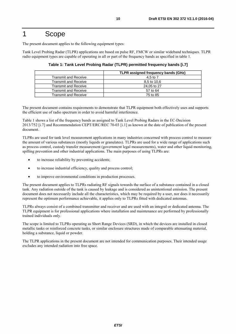
Tank Level Probing Radar (TLPR) applications are based on pulse RF, FMCW or similar wideband techniques. TLPR radio equipment types are capable of operating in all or part of the frequency bands as specified in table 1.
Table 1: Tank Level Probing Radar (TLPR) permitted frequency bands [i.7]
TLPR assigned frequency bands (GHz) Transmit and Receive 4,5 to 7 Transmit and Receive 8,5 to 10,6 Transmit and Receive 24,05 to 27 Transmit and Receive 57 to 64 Transmit and Receive 75 to 85
The present document contains requirements to demonstrate that TLPR equipment both effectively uses and supports the efficient use of radio spectrum in order to avoid harmful interference.
Table 1 shows a list of the frequency bands as assigned to Tank Level Probing Radars in the EC-Decision 2013/752 [i.7] and Recommendation CEPT/ERC/REC 70-03 [i.1] as known at the date of publication of the present document.
TLPRs are used for tank level measurement applications in many industries concerned with process control to measure the amount of various substances (mostly liquids or granulates). TLPRs are used for a wide range of applications such as process control, custody transfer measurement (government legal measurements), water and other liquid monitoring, spilling prevention and other industrial applications. The main purposes of using TLPRs are:
• to increase reliability by preventing accidents;
• to increase industrial efficiency, quality and process control;
• to improve environmental conditions in production processes.
The present document applies to TLPRs radiating RF signals towards the surface of a substance contained in a closed tank. Any radiation outside of the tank is caused by leakage and is considered as unintentional emission. The present document does not necessarily include all the characteristics, which may be required by a user, nor does it necessarily represent the optimum performance achievable, it applies only to TLPRs fitted with dedicated antennas.
TLPRs always consist of a combined transmitter and receiver and are used with an integral or dedicated antenna. The TLPR equipment is for professional applications where installation and maintenance are performed by professionally trained individuals only.
The scope is limited to TLPRs operating as Short Range Devices (SRD), in which the devices are installed in closed metallic tanks or reinforced concrete tanks, or similar enclosure structures made of comparable attenuating material, holding a substance, liquid or powder.
The TLPR applications in the present document are not intended for communication purposes. Their intended usage excludes any intended radiation into free space.

ETSI
Draft ETSI EN 302 372 V2.1.0 (2016-04) 11
2 References
2.1 Normative references References are either specific (identified by date of publication and/or edition number or version number) or non-specific. For specific references, only the cited version applies. For non-specific references, the latest version of the referenced document (including any amendments) applies.
Referenced documents which are not found to be publicly available in the expected location might be found at http://docbox.etsi.org/Reference.
NOTE: While any hyperlinks included in this clause were valid at the time of publication, ETSI cannot guarantee their long term validity.
The following referenced documents are necessary for the application of the present document.
[1] ETSI TR 100 028 (all parts) (V1.4.1) (12-2001): "Electromagnetic compatibility and Radio spectrum Matters (ERM); Uncertainties in the measurement of mobile radio equipment characteristics".
[2] CISPR 16-1-1 (2015): "Specification for radio disturbance and immunity measuring apparatus and methods; Part 1-1: Radio disturbance and immunity measuring apparatus - Measuring apparatus".
[3] ETSI TR 102 273 (all parts) (V1.2.1) (12-2001): "Electromagnetic compatibility and Radio spectrum Matters (ERM); Improvement on Radiated Methods of Measurement (using test site) and evaluation of the corresponding measurement uncertainties".
[4] ANSI C63.5 (2006): "American National Standard for Electromagnetic Compatibility - Radiated Emission Measurements in Electromagnetic Interference (EMI) Control - Calibration of Antennas (9 kHz to 40 GHz)".
[5] ETSI EN 303 883 (V1.1.0) (02-2016): "Short Range Devices (SRD) using Ultra Wide Band (UWB); Measurement Techniques".
[6] ETSI TS 103 361 (V1.1.1) (03-2016): "Short Range Devices (SRD) using Ultra Wide Band technology (UWB); Receiver technical requirements, parameters and measurement procedures to fulfil the requirements of the Directive 2014/53/EU".
2.2 Informative references References are either specific (identified by date of publication and/or edition number or version number) or non-specific. For specific references, only the cited version applies. For non-specific references, the latest version of the referenced document (including any amendments) applies.
NOTE: While any hyperlinks included in this clause were valid at the time of publication, ETSI cannot guarantee their long term validity.
The following referenced documents are not necessary for the application of the present document but they assist the user with regard to a particular subject area.
[i.1] CEPT/ERC/Recommendation 70-03: "Relating to the use of Short Range Devices (SRD)".
[i.2] Recommendation ITU-R SM.1754: "Measurement techniques of Ultra-wideband transmissions".
[i.3] ETSI TS 103 051: "Electromagnetic compatibility and Radio spectrum Matters (ERM); Expanded measurement uncertainty for the measurement of radiated electromagnetic fields".
[i.4] ETSI TS 103 052: "Electromagnetic compatibility and Radio spectrum Matters (ERM); Radiated measurement methods and general arrangements for test sites up to 100 GHz".
[i.5] Recommendation ITU-R P.676-10 (09-2013): "Attenuation by atmospheric gases".

ETSI
Draft ETSI EN 302 372 V2.1.0 (2016-04) 12
[i.6] Directive 2014/53/EU of the European Parliament and of the Council of 16 April 2014 on the harmonisation of the laws of the Member States relating to the making available on the market of radio equipment and repealing Directive 1999/5/EC, (OJ L153, 22.5.2014, p62).
[i.7] European Commission Decision 2013/752/EU amending Decision 2006/771/EC on harmonisation of the radio spectrum for use by short-range devices and repealing Decision 2005/928/EC.
[i.8] Commission Implementing Decision C(2015) 5376 final of 4.8.2015 on a standardisation request to the European Committee for Electrotechnical Standardisation and to the European Telecommunications Standards Institute as regards radio equipment in support of Directive 2014/53/EU of the European Parliament and of the Council.
[i.9] European Commission Decision 2009/343/EC amending Decision 2007/131/EC on allowing the use of the radio spectrum for equipment using ultra-wideband technology in a harmonised manner in the Community.
[i.10] ETSI TR 102 215: "Electromagnetic compatibility and Radio spectrum Matters (ERM); Recommended approach, and possible limits for measurement uncertainty for the measurement of radiated electromagnetic fields above 1 GHz".
[i.11] CEPT/ERC/REC 74-01 (2005): "Unwanted emissions in the spurious domain".
3 Definitions, symbols and abbreviations
3.1 Definitions For the purposes of the present document, the following terms and definitions apply:
ActivityFactor (AF): factor which is used to describe different modulation parameters and activity levels of TLPR devices and defined as the ratio of active measurement periods tmeas (bursts, sweeps, scans) within the overall repetitive measurement cycle Tmeas_cycle, i.e. tmeas/Tmeas_cycle
dedicated antenna: antenna that is designed as an indispensable part of the equipment
Device Under Test (DUT): TLPR under test without a test tank
Duty cycle (DC): ratio of the total on time of the transmitter to the total time in any one hour period reflecting normal operational mode
emissions: signals that leaked or are scattered into the air within the frequency range (that includes harmonics) which depend on equipment's operating bandwidth
NOTE: For TLPRs there is no intended emission outside the tank.
Equipment Under Test (EUT): TLPR under test mounted on a test tank
equivalent isotropically radiated power (e.i.r.p.): total power transmitted, assuming an isotropic radiator
NOTE: e.i.r.p. is conventionally the product of "power into the antenna" and "antenna gain". e.i.r.p. is used for both peak and average power.
equivalent radiated power (e.r.p.): total power transmitted, assuming a directional power transmitted from a theoretical half-wave dipole antenna radiator
Frequency Modulated Continuous Wave (FMCW) radar: radar where the transmitter power is fairly constant but possibly zero during periods giving a big duty cycle (such as 0,1 to 1)
NOTE: The frequency is modulated in some way giving a very wideband spectrum with a power versus time variation which is clearly not pulsed.
integral antenna: permanent fixed antenna, which may be built-in, designed as an indispensable part of the equipment
operating frequency (operating centre frequency): nominal frequency at which equipment is operated
ETSI
Draft ETSI EN 302 372 V2.1.0 (2016-04) 13
power spectral density (psd): amount of the total power inside the measuring receiver bandwidth expressed in dBm/MHz
pulsed radar (or here simply "pulsed TLPR"): radar where the transmitter signal has a microwave power consisting of short RF pulses
Pulse Repetition Frequency (PRF): inverse of the Pulse Repetition Interval (PRI), averaged over a sufficiently long time to cover all PRF variations
Pulse Repetition Interval (PRI): time period between two consecutive transmit pulses in a pulsed TLPR
radiated measurements: measurements that involve the absolute measurement of a radiated field
radiation: signals emitted intentionally inside a tank for level measurements
step response time (of a TLPR): time span after a sudden distance change until the output value (distance value) reaches 90 % of the final value for the first time
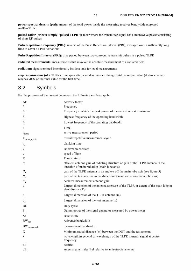
3.2 Symbols For the purposes of the present document, the following symbols apply:
AF Activity factor f Frequency fC Frequency at which the peak power of the emission is at maximum
fH Highest frequency of the operating bandwidth
fL Lowest frequency of the operating bandwidth
t Time tmeas active measurement period
Tmeas_cycle overall repetitive measurement cycle
tG blanking time
k Boltzmann constant c speed of light T Temperature efficient antenna gain of radiating structure or gain of the TLPR antenna in the
direction of main radiation (main lobe axis) gain of the TLPR antenna in an angle α off the main lobe axis (see figure 5) gain of the test antenna in the direction of main radiation (main lobe axis) declared measurement antenna gain d Largest dimension of the antenna aperture of the TLPR or extent of the main lobe in
slant distance RT
d1 Largest dimension of the TLPR antenna (m)
d2 Largest dimension of the test antenna (m)
DC Duty cycle Ps Output power of the signal generator measured by power meter
Δf Bandwidth BWref reference bandwidth
BWmeasured measurement bandwidth
X Minimum radial distance (m) between the DUT and the test antenna wavelength in general or wavelength of the TLPR transmit signal at centre
frequency dB deciBel dBi antenna gain in deciBel relative to an isotropic antenna

ETSI
Draft ETSI EN 302 372 V2.1.0 (2016-04) 14
relative permittivity of the surface material in the real measurement scenario Rmax maximum measurement distance which the individual sensor is still able to reliably
measure under the influence of an interferer Δd measurement value variation over time during a distance measurement
tpulse pulse duration in a pulsed system or the duration of an individual frequency step in an SFCW modulation scheme
_ _ received echo power in the real measurement scenario in Watt (in dBm) maximum value of peak power of the TLPR in Watt (in dBm) in the real
measurement scenario maximum measurement distance of the TLPR under interference conditions slant distance between TLPR and target distance between TLPR and test antenna reflection coefficient of the considered surface in the real measurement scenario radius of the conducting sphere
_ _ received echo power in the equivalent measurement scenario in Watt (in dBm) Radar cross section (RCS) of a target Radar cross section (RCS) of a conducting sphere
_ _ received interferer power at the location of the TLPR in Watt (in dBm)
_ _ transmitted interferer power (generated by the signal generator) in Watt (in dBm) wavelength of the interfering signal
!" (#$%) coupling loss of the directional coupler between ports 1 and 2 in dB
!" (#$&) coupling loss of the directional coupler between ports 1 and 3 in dB
!'_( cable loss of coaxial RF-cable A in dB !'_ cable loss of coaxial RF-cable B in dB _( attenuation of the coaxial attenuator A in dB _ attenuation of the coaxial attenuator B in dB /) Radar cross sections of the square/triangular shaped corner reflector in boresight
direction edge length of corner reflector (compare figure M.1) distance from the TLPR antenna to the inner boundary of the far-field region & half power beamwidth (HPBW) or opening angle of the antenna pattern
3.3 Abbreviations For the purposes of the present document, the following abbreviations apply:
AC Alternate Current AF Activity Factor APC Adaptive Power Control CW Continuous Wave DAA Detect And Avoid DC Duty Cycle DUT Device Under Test e.i.r.p. equivalent isotropically radiated power EMC ElectroMagnetic Compatibility ERC European Radiocommunication Committee e.r.p. equivalent radiatied power EUT Equipment Under Test FH Frequency Hopping FM Frequency Modulated FMCW Frequency Modulated Continuous Wave FSK Frequency Shift Keying
ETSI
Draft ETSI EN 302 372 V2.1.0 (2016-04) 15
FSL Free Space Loss HPBW Half Power Beamwidth IF Intermediate Frequency LBT Listen Before Talk LDC Low Duty Cycle LNA Low Noise Amplifier LO Local Oscillator LPR Level Probing Radar OATS Open Area Test Site PRF Pulse Repetition Frequency PRI Pulse Repetition Interval PSD Power Spectral Density RBW Resolution BandWidth RCS Radar Cross Section RF Radio Frequency RMS Root Mean Square RX Receiver SA Spectrum Analyser SFCW Stepped Frequency Continuous Wave SNR Signal to Noise Ratio SRD Short Range Device TLPR Tank Level Probing Radar TX Transmitter TX/RX Transmit/Receive UWB Ultra-WideBand VBW Video BandWidth VSWR Voltage Standing Wave Ratio
4 Technical requirements specifications
4.1 Environmental conditions The technical requirements of the present document apply under the environmental profile for operation of the equipment, which shall be declared by the supplier. The equipment shall comply with all the technical requirements of the present document at all times when operating within the boundary limits of the declared operational environmental profile. The normal test conditions are defined in clause 5.2.4.
4.2 General Tank Level Probing Radar (TLPR) applications are based on pulse RF, FMCW or similar wideband techniques. TLPR radio equipment types are capable of operating in all or part of the frequency bands as specified in table 1.
4.3 Transmitter conformance requirements
4.3.1 Permitted frequency range of operation
4.3.1.1 Applicability
This requirement shall apply to all DUT.
4.3.1.2 Description
The permitted frequency ranges of operation are the assigned frequency bands for Tank Level Probing Radar (TLPR). They are given in clause 4.3.1.3 table 2.
4.3.1.3 Limits
The permitted frequency range of operation shall be within the limits given in table 2.
ETSI
Draft ETSI EN 302 372 V2.1.0 (2016-04) 16
Table 2: Permitted frequency ranges of operation [i.7]
4,5 GHz to 7 GHz 8,5 GHz to 10,6 GHz 24,05 GHz to 27 GHz
57 GHz to 64 GHz 75 GHz to 85 GHz
Outside the permitted frequency ranges of operation the radiations shall be reduced by no less than 10 dB relative to the maximum power at the frequency fC.
4.3.1.4 Conformance
The compliance of the equipment under test with the permitted frequency ranges of operation shall be considered under clause 4.3.2.
4.3.2 Operating bandwidth
4.3.2.1 Applicability
This requirement shall apply to all DUT.
4.3.2.2 Description
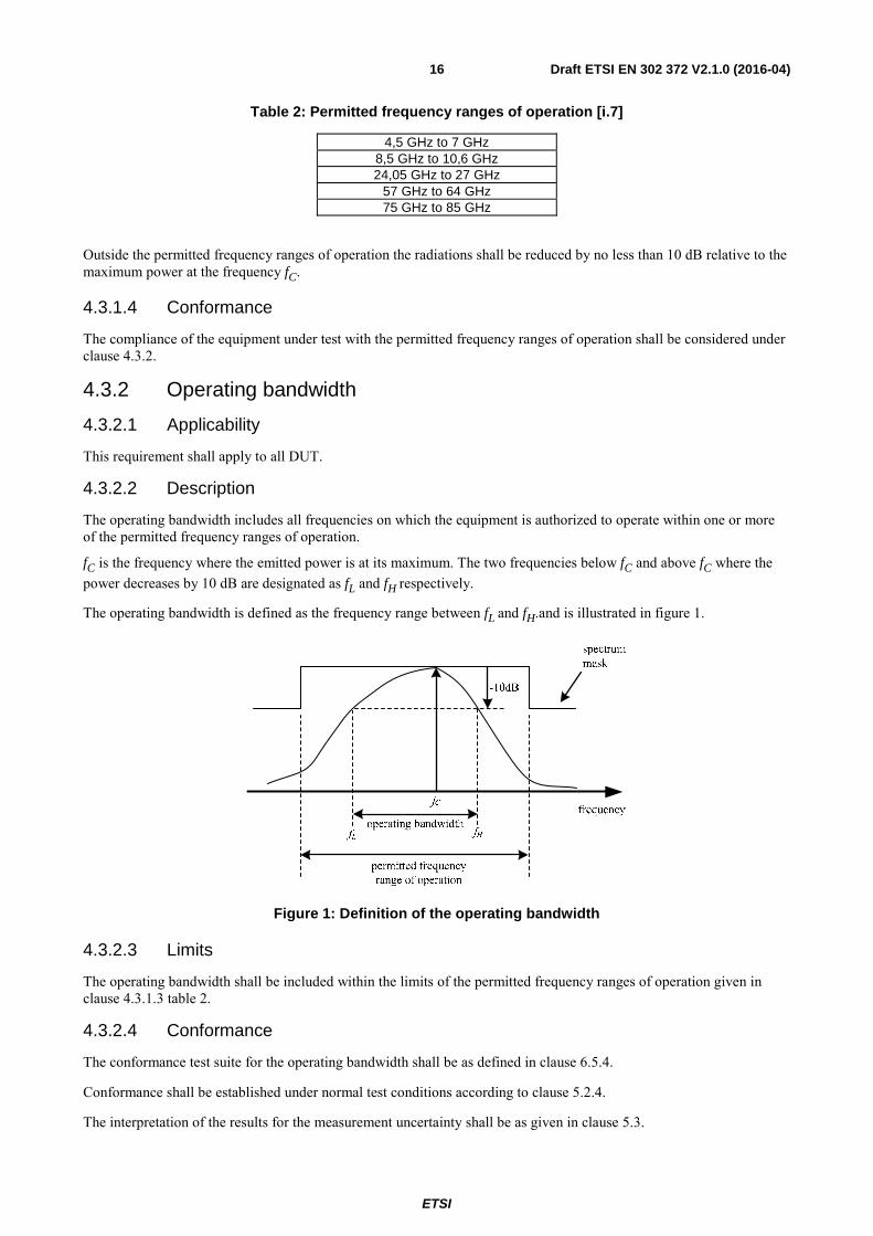
The operating bandwidth includes all frequencies on which the equipment is authorized to operate within one or more of the permitted frequency ranges of operation.
fC is the frequency where the emitted power is at its maximum. The two frequencies below fC and above fC where the power decreases by 10 dB are designated as fL and fH respectively.
The operating bandwidth is defined as the frequency range between fL and fH.and is illustrated in figure 1.
Figure 1: Definition of the operating bandwidth
4.3.2.3 Limits
The operating bandwidth shall be included within the limits of the permitted frequency ranges of operation given in clause 4.3.1.3 table 2.
4.3.2.4 Conformance
The conformance test suite for the operating bandwidth shall be as defined in clause 6.5.4.
Conformance shall be established under normal test conditions according to clause 5.2.4.
The interpretation of the results for the measurement uncertainty shall be as given in clause 5.3.

ETSI
Draft ETSI EN 302 372 V2.1.0 (2016-04) 17
4.3.3 Maximum value of mean power spectral density
Not applicable to Tank Level Probing Radar.
4.3.4 Maximum value of peak power
4.3.4.1 Applicability
This requirement shall apply to all DUT.
4.3.4.2 Description
The maximum peak power specified as e.i.r.p. contained in a 50 MHz bandwidth within the permitted frequency band of operation (clause 4.3.1), radiated in the direction of the maximum level under the specified conditions of measurement.
4.3.4.3 Limits
The maximum peak power limit shall not exceed the limits given in table 3.
Table 3: Maximum peak power limit e.i.r.p. [i.7]
Assigned frequency band Maximum peak power (dBm, measured in 50 MHz)
(within main beam) 4,5 GHz to 7 GHz +24
8,5 GHz to 10,6 GHz +30 24,05 GHz to 27 GHz +43
57 GHz to 64 GHz +43 75 GHz to 85 GHz +43
4.3.4.4 Conformance
The conformance test suite for maximum value of peak power shall be as defined in clause 6.5.6.2 for the radiated test-setup and in clause 6.5.6.3 for the conducted test setup.
The manufacturer shall declare which test-setup is used. This should be stated in the test report.
Conformance shall be established under normal test conditions according to clause 5.2.4.
The interpretation of the results for the measurement uncertainty shall be as given in clause 5.3.
4.3.5 Exterior limits
Not applicable to Tank Level Probing Radar.
4.3.6 Low duty cycle
Not applicable to Tank Level Probing Radar.
4.3.7 Other emissions
Not applicable to Tank Level Probing Radar.
4.3.8 Transmitter unwanted emissions
4.3.8.1 Applicability
This requirement shall apply to all DUT.
ETSI
Draft ETSI EN 302 372 V2.1.0 (2016-04) 18
4.3.8.2 Description
The transmitter unwanted emissions are leakage signals from a tank structure including an installed TLPR. Leakage emissions from the test setup include all emissions: TX, RX and other spurious emissions. They are measured as maximum mean power spectral density (specified as e.i.r.p.) of the radio device under test. The frequency ranges are specified in table 4.
4.3.8.3 Limits
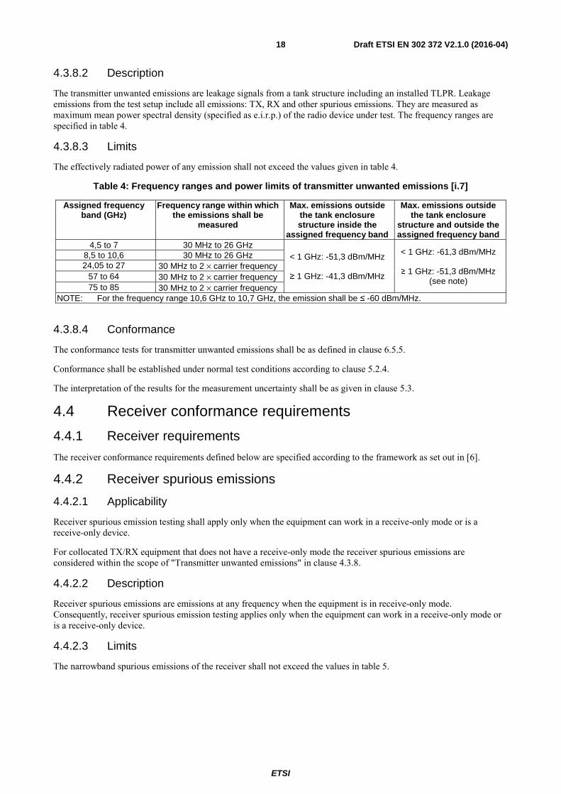
The effectively radiated power of any emission shall not exceed the values given in table 4.
Table 4: Frequency ranges and power limits of transmitter unwanted emissions [i.7]
Assigned frequency band (GHz)
Frequency range within which the emissions shall be
measured
Max. emissions outside the tank enclosure structure inside the
assigned frequency band
Max. emissions outside the tank enclosure
structure and outside the assigned frequency band
4,5 to 7 30 MHz to 26 GHz < 1 GHz: -51,3 dBm/MHz
≥ 1 GHz: -41,3 dBm/MHz
< 1 GHz: -61,3 dBm/MHz
≥ 1 GHz: -51,3 dBm/MHz (see note)
8,5 to 10,6 30 MHz to 26 GHz 24,05 to 27 30 MHz to 2 × carrier frequency
57 to 64 30 MHz to 2 × carrier frequency 75 to 85 30 MHz to 2 × carrier frequency
NOTE: For the frequency range 10,6 GHz to 10,7 GHz, the emission shall be ≤ -60 dBm/MHz.
4.3.8.4 Conformance
The conformance tests for transmitter unwanted emissions shall be as defined in clause 6.5.5.
Conformance shall be established under normal test conditions according to clause 5.2.4.
The interpretation of the results for the measurement uncertainty shall be as given in clause 5.3.
4.4 Receiver conformance requirements
4.4.1 Receiver requirements
The receiver conformance requirements defined below are specified according to the framework as set out in [6].
4.4.2 Receiver spurious emissions
4.4.2.1 Applicability
Receiver spurious emission testing shall apply only when the equipment can work in a receive-only mode or is a receive-only device.
For collocated TX/RX equipment that does not have a receive-only mode the receiver spurious emissions are considered within the scope of "Transmitter unwanted emissions" in clause 4.3.8.
4.4.2.2 Description
Receiver spurious emissions are emissions at any frequency when the equipment is in receive-only mode. Consequently, receiver spurious emission testing applies only when the equipment can work in a receive-only mode or is a receive-only device.
4.4.2.3 Limits
The narrowband spurious emissions of the receiver shall not exceed the values in table 5.

ETSI
Draft ETSI EN 302 372 V2.1.0 (2016-04) 19
Table 5: Narrowband spurious emission limits for receivers [i.11]
Frequency range Limit 30 MHz to 1 GHz -57 dBm (e.r.p.)
above 1 GHz to 40 GHz -47 dBm (e.i.r.p.)
The above limit values apply to narrowband emissions, e.g. as caused by local oscillator leakage.
Wideband spurious emissions shall not exceed the values given in table 6.
Table 6: Wideband spurious emission limits for receivers [i.11]
Frequency range Limit 30 MHz to 1 GHz -61,3 dBm/MHz (e.r.p.)
above 1 GHz to 40 GHz -51,3 dBm/MHz (e.i.r.p.)
4.4.2.4 Conformance
The conformance test suite for the receiver spurious emissions shall be as defined in clause 6.5.5.
Conformance shall be established under normal test conditions according to clause 5.2.4.
The interpretation of the results for the measurement uncertainty shall be as given in clause 5.3.
4.4.3 Interferer signal handling
4.4.3.1 Applicability
This requirement shall apply to all DUT.
4.4.3.2 Description
Interferer signal handling is defined as the capability of the device to properly operate in coexistence with interferers in a defined frequency range without exceeding a given degradation due to the presence of an interfering input signal at the receiver.
This quality of the Radar under test ensures a proper operation in an environment where several users share an assigned frequency band and demonstrates the efficient use of radio spectrum by way of an increased resilience against harmful interference in the operating bandwidth of the Radar under test.
The intended use of a TLPR device is to measure the distance to a liquid or solid material, for example in a tank, in order to determine its filling level. The performance criterion for interferer signal handling is the distance value variation Δd which is observed during the measurement against a fixed Radar target over a defined period of time under the influence of an interfering signal.
The measurement target in this real scenario (see clause 6.6.3.3) is a smooth flat surface consisting of a material with relative permittivity in a defined distance to the TLPR antenna. In this scenario a specular reflection at the surface can be assumed.
The manufacturer states the combination of the minimum relative permittivity and the maximum measurement distance Rmax which the individual TLPR sensor is still able to reliably measure under the influence of an interferer using a specific antenna with gain.
The values for , Rmax and shall be noted in the user manual and in the "application form for testing". The template of this form can be found in annex B.
The measurement value variation Δd observed under interference conditions over at least 120 seconds or 40 times the step response time of the sensor, whichever is longer, shall not exceed a defined limit.

ETSI
Draft ETSI EN 302 372 V2.1.0 (2016-04) 20
4.4.3.3 Limits
The maximum allowed measured distance value variation Δd under interference conditions shall not exceed ±50 mm.
EXAMPLE: The manufacturer states for example that for a K-band TLPR sensor with an antenna gain of 25 dBi (centre frequency 25 GHz) , the maximum allowed measurement value variation of Δd = ±50 mm is still met under the influence of an interfering signal for a maximum measurement distance of 25 m against a material with a relative permittivity = 4,5.
The performance criterion and the level of performance shall be stated in the user manual and in the "application form for testing".
The following text shall be used in the user manual:
"For the receiver test that covers the influence of an interferer signal to the device, the performance criterion has at least the following level of performance according to ETSI TS 103 361 [6].
• Performance criterion: measurement value variation Δd over time during a distance measurement
• Level of performance: Δd ≤ ± 50 mm"
4.4.3.4 Conformance
The conformance test suite for interferer signal handling shall be as defined in clause 6.6.3.5 for the radiated equivalent scenario.
The conformance test suite for interferer signal handling shall be as defined in clause 6.6.3.6 for the conducted equivalent scenario.
The conformance test suite for interferer signal handling shall be as defined in clause 6.6.3.9 for the radiated alternative scenario.
The conformance test suite for interferer signal handling shall be as defined in clause 6.6.3.10 for the conducted alternative equivalent scenario.
Thus there are altogether four possible test setups, which can be equivalently used in order to demonstrate the conformity of the DUT. The manufacturer shall declare which test setup is used. This shall be stated in the test report.
Conformance shall be established under normal test conditions according to clause 5.2.4.
The interpretation of the results for the measurement uncertainty shall be as given in clause 5.3.
4.5 Requirements for spectrum access
4.5.1 Detect and avoid (DAA)
Not applicable to Tank Level Probing Radar.
4.5.2 Listen-before-talk (LBT)
Not applicable to Tank Level Probing Radar.
4.5.3 Low duty cycle (LDC)
Not applicable to Tank Level Probing Radar.
4.6 Antenna requirements Not applicable to Tank Level Probing Radar.
ETSI
Draft ETSI EN 302 372 V2.1.0 (2016-04) 21
4.7 Other requirements and mitigation techniques
4.7.1 General
The implementation of a mitigation technique is not required for TLPR equipment covered by the present document. However, the DUT can apply one or more mitigation techniques described in clauses 4.7.2 to 4.7.8. If mitigation techniques are applied, the measured emission values in clauses 4.3.4.3 and 4.3.8.3 shall be reduced by the values provided by the mitigation techniques according to the following equation:
Final value (dBm/MHz or dBm) = Measured value (dBm/MHz or dBm) - total mitigation factor (dB)
The mitigation factors are classified into following categories:
• activity factor and duty cycle;
• frequency domain mitigation;
• shielding effects;
• equivalent mitigation techniques.
Mitigation factors are declared and need sufficiently be demonstrated and documented by the provider before taking into account in the above stated equation.
The range of modulation parameters in clause 4.7.9 is considered to be an "other requirement". Therefore it cannot be used as a mitigation technique.
4.7.2 Adaptive power control (APC)
Not applicable to Tank Level Probing Radar.
4.7.3 Activity factor and duty cycle
4.7.3.1 Applicability
This requirement shall apply to all DUT which implemented this mitigation technique. The usage shall be declared by the manufacturer.
4.7.3.2 Description
The activity factor (AF) of the TLPR device can be taken into account for additional mitigation considerations. This activity factor is also sometimes referred to as "duty cycle resulting from user" in some sources dealing with UWB devices. The AF as well as spreading of subsequent pulses on different frequencies can be used as an additional mitigation technique. Further information is given in annex J on TLPR modulation schemes. An AF and/or spreading of subsequent pulses on different frequencies of 10 % represent an interference mitigation of 10 dB. Examples are: power on-/off-gating, dithering, etc.
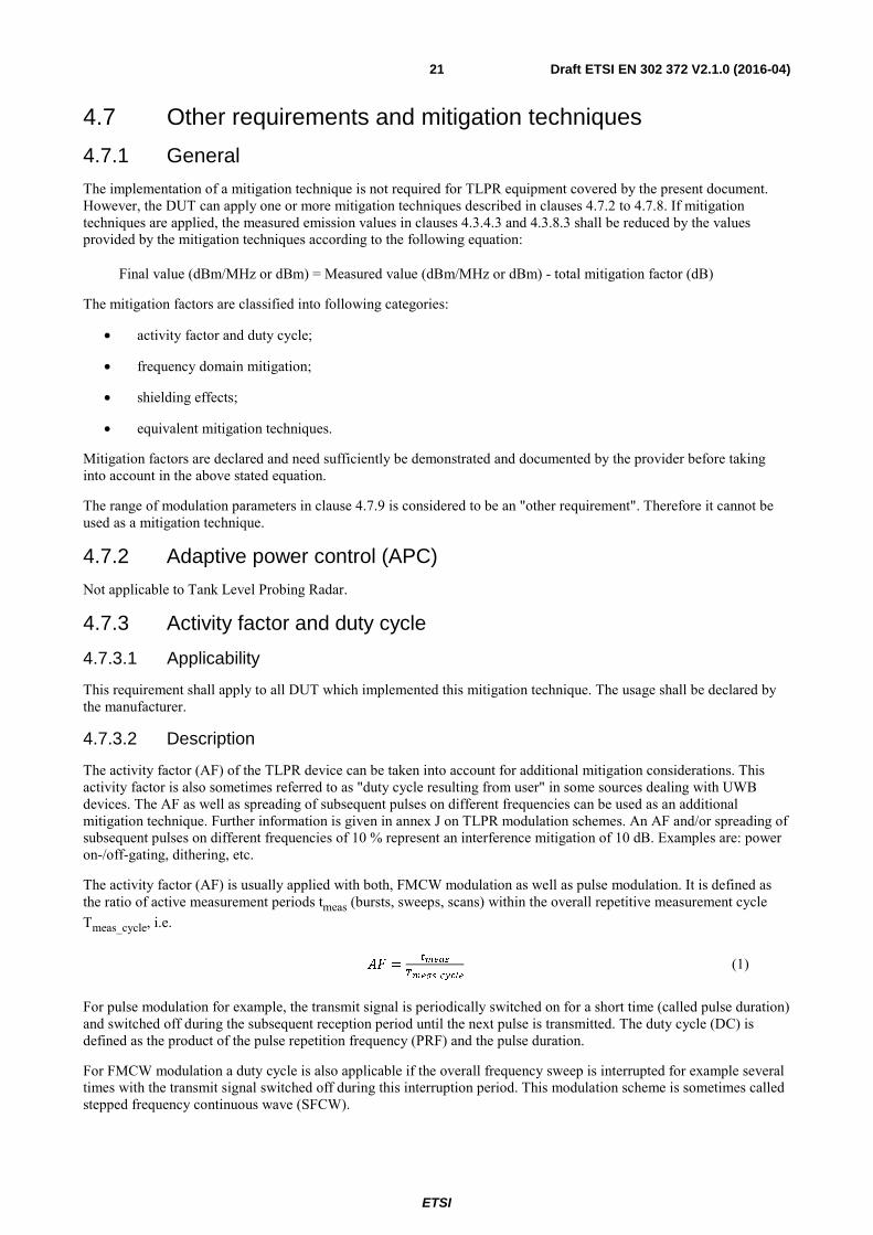
The activity factor (AF) is usually applied with both, FMCW modulation as well as pulse modulation. It is defined as the ratio of active measurement periods tmeas (bursts, sweeps, scans) within the overall repetitive measurement cycle Tmeas_cycle, i.e.
=
_ (1)
For pulse modulation for example, the transmit signal is periodically switched on for a short time (called pulse duration) and switched off during the subsequent reception period until the next pulse is transmitted. The duty cycle (DC) is defined as the product of the pulse repetition frequency (PRF) and the pulse duration.
For FMCW modulation a duty cycle is also applicable if the overall frequency sweep is interrupted for example several times with the transmit signal switched off during this interruption period. This modulation scheme is sometimes called stepped frequency continuous wave (SFCW).
ETSI
Draft ETSI EN 302 372 V2.1.0 (2016-04) 22
In sources dealing with UWB devices this duty cycle is sometimes called "duty cycle resulting from modulation". Further information about duty cycle can be extracted from annex J.
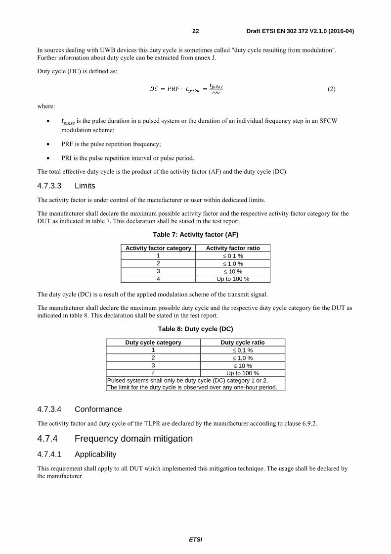
Duty cycle (DC) is defined as:
= ∙ =
*+, (2)
where:
• tpulse is the pulse duration in a pulsed system or the duration of an individual frequency step in an SFCW modulation scheme;
• PRF is the pulse repetition frequency;
• PRI is the pulse repetition interval or pulse period.
The total effective duty cycle is the product of the activity factor (AF) and the duty cycle (DC).
4.7.3.3 Limits
The activity factor is under control of the manufacturer or user within dedicated limits.
The manufacturer shall declare the maximum possible activity factor and the respective activity factor category for the DUT as indicated in table 7. This declaration shall be stated in the test report.
Table 7: Activity factor (AF)
Activity factor category Activity factor ratio 1 ≤ 0,1 % 2 ≤ 1,0 % 3 ≤ 10 % 4 Up to 100 %
The duty cycle (DC) is a result of the applied modulation scheme of the transmit signal.
The manufacturer shall declare the maximum possible duty cycle and the respective duty cycle category for the DUT as indicated in table 8. This declaration shall be stated in the test report.
Table 8: Duty cycle (DC)
Duty cycle category Duty cycle ratio 1 ≤ 0,1 % 2 ≤ 1,0 % 3 ≤ 10 % 4 Up to 100 %
Pulsed systems shall only be duty cycle (DC) category 1 or 2. The limit for the duty cycle is observed over any one-hour period.
4.7.3.4 Conformance
The activity factor and duty cycle of the TLPR are declared by the manufacturer according to clause 6.9.2.
4.7.4 Frequency domain mitigation
4.7.4.1 Applicability
This requirement shall apply to all DUT which implemented this mitigation technique. The usage shall be declared by the manufacturer.
ETSI
Draft ETSI EN 302 372 V2.1.0 (2016-04) 23
4.7.4.2 Description
For SFCW/FMCW modulation, the instantaneous bandwidth of the radar signal is close to zero. The mitigation naturally offered by SFCW/FMCW radar is the zero instantaneous bandwidth. The swept band over longer time is not able to generate simultaneous interferences to the victim receivers. For instance, the stepped frequency continuous wave Radar (SFCW) sweeps ca. 1 000 steps, within a period of approx. 100 ms. At each step the radar transmits a different frequency with dwell time of 100 μs within 1 MHz. For a 10 MHz victim receiver bandwidth, the equivalent duty cycle is 10 × 100 μs / 100 ms = 1 %. This is equivalent to a mitigation factor of 20 dB.
4.7.4.3 Limits
Limits for modulation parameters are given in clause J.2.
4.7.4.4 Conformance
The frequency domain mitigation of the TLPR is declared by the manufacturer according to clause 6.9.3.
4.7.5 Shielding effects
4.7.5.1 Applicability
This requirement shall apply to all DUT.
4.7.5.2 Description
The installation requirements of Tank Level Probing Radar equipment to ensure a proper shielding can be found in annex E.
Annex F specifies the requirements of the test tank.
4.7.5.3 Limits
Not applicable.
4.7.5.4 Conformance
The product manual shall have the necessary information to enable a correct installation of the TLPR equipment according to clause 6.9.4.
4.7.6 Thermal radiation
Not applicable to Tank Level Probing Radar.
4.7.7 Site registration
Not applicable to Tank Level Probing Radar.
4.7.8 Equivalent mitigation techniques
4.7.8.1 Applicability
This requirement shall apply to all DUT which implemented this mitigation technique. The usage shall be declared by the manufacturer.
4.7.8.2 Description
Other mitigation techniques and mitigation factors can be taken into account for the calculation of the maximum allowed TX power of a TLPR device, as long as reached mitigation factors are equivalent or higher than the mitigation factors reached using the presented techniques in the present document. Examples for additional mitigation factors could be the deployment of the radio device in a restricted indoor area with higher wall attenuation. The additional mitigation factors need to be weighed against the specific services to be protected.
The manufacturer shall provide sufficient information for determining compliance with the TLPR emission limits in clauses 4.3.8 when using equivalent mitigation techniques.

ETSI
Draft ETSI EN 302 372 V2.1.0 (2016-04) 24
NOTE: Regulations in the EC Decision 2009/343/EC [i.9] allow for other equivalent mitigation techniques to be used across all frequency bands, where these offer at least equivalent protection to that provided by the limits in the decision.
4.7.8.3 Limits
Not applicable.
4.7.8.4 Conformance
The equivalent mitigation techniques of the TLPR shall be declared by the manufacturer. No test needs to be conducted.
4.7.9 Range of modulation parameters
4.7.9.1 Applicability
This requirement shall apply to all DUT.
4.7.9.2 Description
The description of the modulation parameters can be found in annex J.
4.7.9.3 Limits
The limits of the modulation parameters are specified in annex J.
4.7.9.4 Conformance
The modulation parameters of the TLPR shall be declared by the manufacturer. No test needs to be conducted.
5 Testing for compliance with technical requirements
5.1 Environmental conditions for testing Tests defined in the present document shall be carried out at representative points within the boundary limits of the declared operational environmental profile.
Where technical performance varies subject to environmental conditions, tests shall be carried out under a sufficient variety of environmental conditions (within the boundary limits of the declared operational environmental profile) to give confidence of compliance for the affected technical requirements.
5.2 General conditions for testing
5.2.1 Product information
Product information required for testing will be stated in the "application form for testing" in annex B.
5.2.2 Product information useful to facilitate testing
Equipment submitted for testing, where applicable, shall fulfil the requirements of the present document on all frequencies over which it is intended to operate.
The provider shall submit one or more samples of the equipment as appropriate for testing.
Additionally, technical documentation and operating manuals, sufficient to allow testing to be performed, shall be supplied.
The performance of the equipment submitted for testing shall be representative of the performance of the corresponding production model. In order to avoid any ambiguity in that assessment, the present document contains instructions for the test conditions and for the choice of equipment for testing purposes (clause 5), technical requirements specifications (clause 4) and the conformance test suits (clause 6).

ETSI
Draft ETSI EN 302 372 V2.1.0 (2016-04) 25
The provider shall offer complete equipment with any auxiliary equipment needed for testing. The provider shall also submit a suitable test tank, as described in annex F.
The equipment submitted by the provider shall be designed, constructed and manufactured in accordance with good engineering practice and with the aim of minimizing harmful interference to other equipment and services.
The equipment shall be marked in a visible place. This marking shall be legible and durable. Where this is not possible due to physical constraints, the marking shall be included in the user's manual.
The marking shall include as a minimum:
• the name of the manufacturer or his trademark;
• the type designation.
In order to facilitate testing, the provider should give the following information:
• technical data in the form in annex B;
• all necessary test signal sources, set-up information, and the test tank shall accompany the equipment when it is submitted for testing.
5.2.3 Requirements for the test modulation
Requirements for the test modulation are specified in ETSI EN 303 883 [5], clause 5.3.
5.2.4 Test conditions, power supply and ambient temperatures
Test conditions, power supply- and ambient temperatures requirements are specified in ETSI EN 303 883 [5], clause 5.4.
5.2.5 Choice of equipment for test suites
The equipment for test suites shall be chosen according to ETSI EN 303 883 [5], clause 5.5.
If the submitted equipment has several optional features, considered not to affect the RF parameters then the tests need only to be performed on the equipment configured with that combination of features considered to create the highest unintentional emissions outside the tank structure.
In addition, when a device has the capability of using different dedicated antennas, tank connections or other features that affect the RF parameters, at least the worst combination of features from an emission point of view as agreed between the provider and the test laboratory shall be tested.
Where the transmitter is designed with adjustable output power, then all transmitter parameters shall be measured using the highest maximum mean power spectral density level, as declared by the provider. The duty cycle and activity factor of the transmitter as declared by the provider shall not be exceeded. The actual duty cycle and activity factor used during the measurements shall be recorded in the test report.
The choice of model(s) for testing shall be recorded in the test report.
5.2.6 Multiple operating bandwidths and multiband equipment
Where equipment has more than one operating bandwidth (e.g. 500 MHz and 1 300 MHz), a minimum of two operating bandwidths shall be chosen such that the lower and higher limits of the operating range(s) of the equipment are covered (see clause 4.3.3). All operating bandwidths of the equipment shall be declared by the equipment manufacturer.
In case of multiband equipment (i.e. equipment that can operate with an operating bandwidth below 4,8 GHz and above 6,0 GHz), the lowest and highest channel in operation of each band shall be tested.
5.2.7 Testing of host connected equipment and plug-in radio devices
Testing of host connected equipment and plug-in radio devices measurements shall be according to ETSI EN 303 883 [5], clause 5.6.

ETSI
Draft ETSI EN 302 372 V2.1.0 (2016-04) 26
5.2.8 Radiated measurement arrangements
All reasonable efforts should be made to clearly demonstrate that emissions from the UWB transmitter do not exceed the specified levels, with the transmitter in the far field. To the extent practicable, the device under test shall be measured at the distance specified in clause B.2.4 and with the specified measurement bandwidths. However, in order to obtain an adequate signal-to-noise ratio in the measurement system, radiated measurements may have to be made at distances less than those specified in clause B.2.4 and/or with reduced measurement bandwidths. The revised measurement configuration should be stated on the test report, together with an explanation of why the signal levels involved necessitated measurement at the distance employed or with the measurement bandwidth used in order to be accurately detected by the measurement equipment and calculations demonstrating compliance.
Where it is not practical to further reduce the measurement bandwidth either because of limitations of commonly available test equipment or difficulties in converting readings taken using one measurement bandwidth to those used by the emission limits in clause 8, and the required measurement distance would be so short that the device would not clearly be within the far field, the test report shall state this fact, the measurement distance and bandwidth used, the near field/far field distance for the measurement setup (see clause B.2.4), the measured device emissions, the achievable measurement noise floor and the frequency range(s) involved.
NOTE: This is called "best measurement practice".
5.3 Interpretation of the measurement results
5.3.1 General
The interpretation of the results for the measurements described in the present document shall be as follows:
1) the measured value related to the corresponding limit shall be used to decide whether an equipment meets the requirements of the present document;
2) the measurement uncertainty value for the measurement of each parameter shall be recorded;
3) the recorded value of the measurement uncertainty shall be wherever possible, for each measurement, equal to or lower than the figures in table 9, and the interpretation procedure specified in clause 5.3.1 shall be used.
For the test methods, according to the present document, the measurement uncertainty figures shall be calculated in accordance with the guidance provided in ETSI TR 100 028 [1] and shall correspond to an expansion factor (coverage factor) k = 1,96 or k = 2 (which provide confidence levels of respectively 95 % and 95,45 % in the case where the distributions characterizing the actual measurement uncertainties are normal (Gaussian)).
Table 9 is based on such expansion factors.

ETSI
Draft ETSI EN 302 372 V2.1.0 (2016-04) 27
Table 9: Maximum measurement uncertainties [i.4]
Parameter Maximum expanded measurement Uncertainty
Radio frequency ±1 x 10⁻⁷ Radiated RF power (up to 40 GHz) ±6 dB Radiated RF power (above 40 GHz up to 66 GHz) ±8 dB Radiated RF power (above 66 GHz up to 100 GHz) ±10 dB (see note 1) Radiated RF power (above 100 GHz) see note 2 Conducted Measurements (up to 18 GHz) ±1,5 dB Conducted Measurements (up to 40 GHz) ±2,5 dB Conducted Measurements (up to 100 GHz) ±4 dB Conducted measurements (above 100 GHz) see note 2 Temperature ±1 °C Humidity ±5 % DC and low frequency voltages ±3 % NOTE 1: Achieved sensitivity and measurement uncertainty are a direct result of the chosen test
suites. The values mentioned together with the concerns should therefore be considered illustrational rather than absolute for radiated measurements above 66 GHz, given the absence of some relevant information. For radiated emissions above 66 GHz the given measurement uncertainties are based on the assumption of the deployment of a cable based measurement set-up.
NOTE 2: For measurements above 100 GHz, the expanded measurement uncertainty shall also be recorded in the test report and a detailed calculation shall be added. A future revision of the present document may include a value for frequencies above 100 GHz for expanded measurement uncertainty that is still under development.
"Standard" measurement equipment is only available up to a frequency range of around 66 GHz with a sensitivity of -72 dBm at 18 GHz down to around -64 dBm at 40 GHz (1 MHz RBW, 3 MHz VBW, 100 MHz span). For higher frequencies the sensitivity will further decrease.
The commercially available calibration capability (only equipment specific calibration, no closed loop to an international norm) is currently limited to around 66 GHz. Thus no such possibility is freely available on the market above that limit. As a consequence measurement results above 66 GHz of different laboratories are not fully comparable since the equipment will not be calibrated for the needed operational range.
The measurement uncertainty of measurements in the range above 40 GHz (millimetre domain) will be clearly above the initially assumed 6 dB for radiated measurements below 40 GHz. A value of 8 dB seems to be more adequate. Precise values of measurement uncertainty require calibration, and there are limitations as mentioned on above.
This maximum uncertainty value above 40 GHz is also dependent upon the maximum dimensions of the antenna of the equipment under test and is also dependent upon gain specifications of antennae.
5.3.2 Conversion loss data and measurement uncertainty
Calibrated conversion loss data for harmonic mixers are given for a dedicated number of harmonic, IF frequency and LO power. They cannot be used for a different number of harmonic. It is equally essential that the LO level at the harmonic mixer matches the LO level for which the conversion loss data have been derived.
The above conditions adhered to a measurement uncertainty including the measuring receiver of < ±3 dB to 5 dB at the frequency of the calibration points can be expected, depending on the waveguide band.
Harmonic mixers frequently have a low return loss (typically 6 dB to 7 dB), which increases the measurement uncertainty. It is therefore expedient to insert an attenuator or isolator between the mixer and the antenna in order to improve measurement uncertainty. However, the insertion loss caused by such a component will reduce the sensitivity of the spectrum analyser and mixer setup. This insertion loss has also to be taken into account for level measurements.
Mixers with integrated isolator are preferable, as they are already calibrated with the isolator included.
ETSI
Draft ETSI EN 302 372 V2.1.0 (2016-04) 28
As frequency ranges increase it may be difficult to conclude a maximum allowable value for the expanded measurement uncertainty due to lack of knowledge of the new methods of test and determining the uncertainty components:
• The commercially available calibration capability is limited to around 66 GHz. Thus no such possibility is freely available on the market above that limit. As a consequence measurement results above 66 GHz of different labs are not fully comparable since the equipment will not be calibrated for the needed operational range and also for radiated unwanted emission measurements above the operational range.
• The expanded measurement uncertainty of measurements in the range between 66 GHz and 100 GHz will be clearly above the values valid for below 66 GHz. Precise values of expanded measurement uncertainty require calibration, and there are limitations as mentioned above.
• In general it has to be mentioned that these values become the higher the frequency will become the more a guideline.
• Starting from around 66 GHz the limits of coaxial systems are reached and the frontend has to switch to wave guide based technologies adding an additional attenuation and also decreasing the sensitivity. Commercially available analysers can only measure up to around 67 GHz, thus making the use of external mixers unavoidable.
Guidance is provided in ETSI TS 103 051 [i.3] that presents an evaluation of maximum acceptable measurement uncertainty for Radio Frequency (RF) electromagnetic field (emf) measurements for the frequency range from 30 MHz to 100 GHz for inclusion within ETSI documents on radio products used for compliance testing.
5.3.3 Measurement uncertainty is equal to or less than maximum acceptable uncertainty
If measurement uncertainty is equal to or less than maximum acceptable uncertainty the interpretation shall be as given in clause 5.7.2 of ETSI EN 303 883 [5].
5.3.4 Measurement uncertainty is greater than maximum acceptable uncertainty
If measurement uncertainty is greater than maximum acceptable uncertainty the interpretation shall be as given in clause 5.7.3 of ETSI EN 303 883 [5].
5.3.5 Emissions
Emissions are measured with TLPR installed in a test tank, see clause 4.3.8. Transmitter unwanted emissions refer to annexes E and F.
6 Conformance test suite
6.1 Introduction Shall be as in ETSI EN 303 883 [5], clause 6.1.
6.2 Initial measurement steps Shall be as in ETSI EN 303 883 [5], clause 6.2.
6.3 Radiated measurements
6.3.1 General
Shall be as in annex C.

ETSI
Draft ETSI EN 302 372 V2.1.0 (2016-04) 29
6.3.2 Test sites and general arrangements for measurements involving the use of radiated fields
Shall be as in annexes E, F and G.
6.3.3 Guidance on the use of a radiation test site
The guidance on the use of a radiation test side shall be as in clause C.2.
The range length shall be as in annex I.
6.3.4 Coupling of signals
Shall be as in clause C.3.
6.3.5 Standard test methods
The calibrated setup shall be as in clause C.4.1 and the substitution method shall be as in clause C.4.2.
6.3.6 Standard calibration method
Shall be as in ETSI EN 303 883 [5], clause 6.3.6.
6.4 Conducted measurements
6.4.1 General Setup
Shall be as in ETSI EN 303 883 [5], clause 6.4.
6.4.2 Specific Setup
Not applicable to Tank Level Probing Radar.
6.5 Conformance test suite for transmitter parameters
6.5.1 General
First the EUT shall be measured for:
• the operating bandwidth(s);
• the maximum value of peak power (e.i.r.p.);
• the transmitter unwanted emissions.
The following methods of measurement shall apply to the testing of stand-alone units and to the equipment configurations identified in clause 5.2.5.
Where the transmitter is designed with adjustable carrier power, then all transmitter parameters shall be measured using the highest peak power level, as declared by the provider. The duty cycle and activity factor of the transmitter as declared by the provider shall not be exceeded. The actual duty cycle and activity factor used during the measurements shall be recorded in the test report.
6.5.2 Method of measurements of the Ultra-Wideband emissions
Not applicable to Tank Level Probing Radar.
6.5.3 Permitted frequency range of operation
No test necessary.
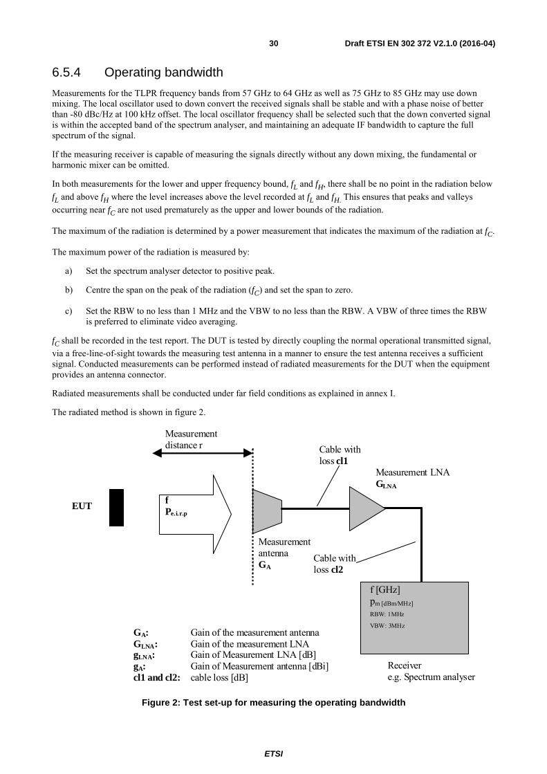
ETSI
Draft ETSI EN 302 372 V2.1.0 (2016-04) 30
6.5.4 Operating bandwidth
Measurements for the TLPR frequency bands from 57 GHz to 64 GHz as well as 75 GHz to 85 GHz may use down mixing. The local oscillator used to down convert the received signals shall be stable and with a phase noise of better than -80 dBc/Hz at 100 kHz offset. The local oscillator frequency shall be selected such that the down converted signal is within the accepted band of the spectrum analyser, and maintaining an adequate IF bandwidth to capture the full spectrum of the signal.
If the measuring receiver is capable of measuring the signals directly without any down mixing, the fundamental or harmonic mixer can be omitted.
In both measurements for the lower and upper frequency bound, fL and fH, there shall be no point in the radiation below fL and above fH where the level increases above the level recorded at fL and fH. This ensures that peaks and valleys occurring near fC are not used prematurely as the upper and lower bounds of the radiation.
The maximum of the radiation is determined by a power measurement that indicates the maximum of the radiation at fC.
The maximum power of the radiation is measured by:
a) Set the spectrum analyser detector to positive peak.
b) Centre the span on the peak of the radiation (fC) and set the span to zero.
c) Set the RBW to no less than 1 MHz and the VBW to no less than the RBW. A VBW of three times the RBW is preferred to eliminate video averaging.
fC shall be recorded in the test report. The DUT is tested by directly coupling the normal operational transmitted signal, via a free-line-of-sight towards the measuring test antenna in a manner to ensure the test antenna receives a sufficient signal. Conducted measurements can be performed instead of radiated measurements for the DUT when the equipment provides an antenna connector.
Radiated measurements shall be conducted under far field conditions as explained in annex I.
The radiated method is shown in figure 2.
EUT
Measurement antenna GA
Measurement distance r
f Pe.i.r.p
Cable with loss cl1
Measurement LNA GLNA
Receiver e.g. Spectrum analyser
GA: Gain of the measurement antenna GLNA: Gain of the measurement LNA gLNA: Gain of Measurement LNA [dB] gA: Gain of Measurement antenna [dBi] cl1 and cl2: cable loss [dB]
Cable with loss cl2
f [GHz] pm [dBm/MHz]
RBW: 1MHz
VBW: 3MHz
Figure 2: Test set-up for measuring the operating bandwidth

ETSI
Draft ETSI EN 302 372 V2.1.0 (2016-04) 31
For radiated measurements, a test site selected from annex A which fulfils the requirements of the specified frequency range and undisturbed lowest specified emission levels of this measurement shall be used. Radiated measurements shall be carried out in an anechoic environment or may also be carried out at an OATS where no physical obstruction shall be within a sector defined as "three times the 3 dB beam width of the antenna" during this test.
The lower and upper frequency bounds fL and fH are measured as follows:
a) Set the spectrum analyser detector to positive peak.
b) Centre the span on the peak of the radiation (fC) and set the span to a reasonable value larger than the expected operating bandwidth.
c) Set the RBW to no less than 1 MHz and the VBW to no less than the RBW. A VBW of three times the RBW is preferred to eliminate video averaging.
d) For the lower frequency bound fL, the radiation is searched from a frequency lower than the peak that has, by inspection, a much lower PSD than the peak PSD -10 dB and increasing in frequency towards the peak until the PSD indicates a level of -10 dB less than at the peak of the radiation.
e) The process is repeated for the upper frequency bound fH, beginning at a frequency higher than the peak that has, by inspection, a much lower PSD than peak PSD -10 dB.
The values for fL and fH shall be recorded in the test report.
6.5.5 Mean power spectral density measurements
This measurement method is used for measuring the maximum value of mean power spectral density within the operating bandwidth and the transmitter unwanted emissions outside the operating bandwidth.
Measurements shall be performed in the frequency ranges given in table 10.
Table 10: Frequency ranges for measurement of emissions
Assigned frequency bands Frequency range within which the emissions shall be measured
4,5 GHz to 7 GHz 30 MHz to 26 GHz 8,5 GHz to 10,6 GHz 30 MHz to 26 GHz 24,05 GHz to 27 GHz 30 MHz to 2 × carrier frequency
57 GHz to 64 GHz 30 MHz to 2 × carrier frequency 75 GHz to 85 GHz 30 MHz to 2 × carrier frequency
For this test, the EUT is defined as a TLPR mounted on a test tank as described in annex F. Relevant information concerning leakage from the EUT is given in annex G.
The dimensions of the test tank shall be recorded in the test report.
An example of the test set-up is illustrated in figure 3.
Measuring test antenna
EUT
Spectrum analyser Amplifier
Power supply
Figure 3: An example of test set-up for emission measurement
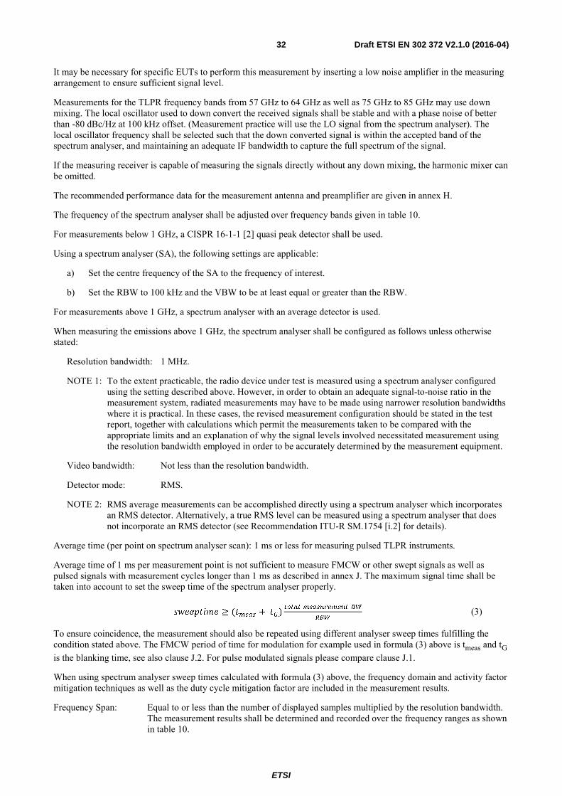
ETSI
Draft ETSI EN 302 372 V2.1.0 (2016-04) 32
It may be necessary for specific EUTs to perform this measurement by inserting a low noise amplifier in the measuring arrangement to ensure sufficient signal level.
Measurements for the TLPR frequency bands from 57 GHz to 64 GHz as well as 75 GHz to 85 GHz may use down mixing. The local oscillator used to down convert the received signals shall be stable and with a phase noise of better than -80 dBc/Hz at 100 kHz offset. (Measurement practice will use the LO signal from the spectrum analyser). The local oscillator frequency shall be selected such that the down converted signal is within the accepted band of the spectrum analyser, and maintaining an adequate IF bandwidth to capture the full spectrum of the signal.
If the measuring receiver is capable of measuring the signals directly without any down mixing, the harmonic mixer can be omitted.
The recommended performance data for the measurement antenna and preamplifier are given in annex H.
The frequency of the spectrum analyser shall be adjusted over frequency bands given in table 10.
For measurements below 1 GHz, a CISPR 16-1-1 [2] quasi peak detector shall be used.
Using a spectrum analyser (SA), the following settings are applicable:
a) Set the centre frequency of the SA to the frequency of interest.
b) Set the RBW to 100 kHz and the VBW to be at least equal or greater than the RBW.
For measurements above 1 GHz, a spectrum analyser with an average detector is used.
When measuring the emissions above 1 GHz, the spectrum analyser shall be configured as follows unless otherwise stated:
Resolution bandwidth: 1 MHz.
NOTE 1: To the extent practicable, the radio device under test is measured using a spectrum analyser configured using the setting described above. However, in order to obtain an adequate signal-to-noise ratio in the measurement system, radiated measurements may have to be made using narrower resolution bandwidths where it is practical. In these cases, the revised measurement configuration should be stated in the test report, together with calculations which permit the measurements taken to be compared with the appropriate limits and an explanation of why the signal levels involved necessitated measurement using the resolution bandwidth employed in order to be accurately determined by the measurement equipment.
Video bandwidth: Not less than the resolution bandwidth.
Detector mode: RMS.
NOTE 2: RMS average measurements can be accomplished directly using a spectrum analyser which incorporates an RMS detector. Alternatively, a true RMS level can be measured using a spectrum analyser that does not incorporate an RMS detector (see Recommendation ITU-R SM.1754 [i.2] for details).
Average time (per point on spectrum analyser scan): 1 ms or less for measuring pulsed TLPR instruments.
Average time of 1 ms per measurement point is not sufficient to measure FMCW or other swept signals as well as pulsed signals with measurement cycles longer than 1 ms as described in annex J. The maximum signal time shall be taken into account to set the sweep time of the spectrum analyser properly.
≥ ( + -)"__.
+. (3)
To ensure coincidence, the measurement should also be repeated using different analyser sweep times fulfilling the condition stated above. The FMCW period of time for modulation for example used in formula (3) above is tmeas and tG is the blanking time, see also clause J.2. For pulse modulated signals please compare clause J.1.
When using spectrum analyser sweep times calculated with formula (3) above, the frequency domain and activity factor mitigation techniques as well as the duty cycle mitigation factor are included in the measurement results.
Frequency Span: Equal to or less than the number of displayed samples multiplied by the resolution bandwidth. The measurement results shall be determined and recorded over the frequency ranges as shown in table 10.
ETSI
Draft ETSI EN 302 372 V2.1.0 (2016-04) 33
In order to obtain the required sensitivity a narrower bandwidth may be necessary, this shall be stated in the test report form.
The test procedure shall be the following:
• A test site such as one selected from annex C (i.e. indoor test site or open area test site), which fulfils the requirements of the specified frequency range of this measurement shall be used.
• The frequency of the measuring receiver shall be adjusted over the frequency range in accordance to table 10. The frequency of each spurious component shall be noted. If the test site is disturbed by radiation coming from outside the site, this qualitative search may be performed in a screened room with reduced distance between the transmitter and the test antenna.
• During the measurement, the test antenna is placed three metres away from the EUT. It may be necessary for specific EUTs to perform this measurement with the test antenna placed closer to the EUT. The distance between EUT and the test antenna shall be recorded in the test report.
• Measurements shall be taken at a sufficient number of radials and polarizations to ensure that the maximum unintentional emission is measured.
The measuring receiver configuration uses a low noise preamplifier and a dipole antenna (for frequencies below 1 GHz) or horn antenna (for frequencies above 1 GHz). Details are given in annex H. For the unwanted emission measurements, a combination of biconical and log periodic dipole array antennas (commonly termed "log periodic") could also be used to cover the entire 30 MHz to 1 000 MHz band.
The measured spectrum curve at the spectrum analyser shall be recorded. For these measurements it is strongly recommended to use a LNA (low noise amplifier) before the spectrum analyser input to achieve the required sensitivity. Measurements below -60 dBm e.i.r.p. (measured in a 1 MHz bandwidth) are not required.
6.5.6 Peak power measurements
6.5.6.1 Description
The maximum peak power (e.i.r.p.) shall be measured over the whole permitted frequency band of operation (clause 4.3.1).
Measurements for the TLPR frequency bands from 57 GHz to 64 GHz as well as 75 GHz to 85 GHz may use down mixing. The local oscillator used to down convert the received signals shall be stable and with a phase noise of better than -80 dBc/Hz at 100 kHz offset. The local oscillator frequency shall be selected such that the down converted signal is within the accepted band of the spectrum analyser, and maintaining an adequate IF bandwidth to capture the full spectrum of the signal.
If the measuring receiver is capable of measuring the signals directly without any down mixing, the fundamental or harmonic mixer can be omitted.
The maximum value of peak power shall be determined and recorded.
The following shall be applied to the combination(s) of the radio device and its intended antennae. In the case that the RF power level is user adjustable, all measurements shall be made with the highest power level available to the user for that combination.
When measuring maximum peak power from the device under test, the spectrum analyser used should be configured as follows:
• Frequency: Centre frequency of operating bandwidth. Reasonable frequency span of the spectrum analyser to cover the operating bandwidth.
• Resolution bandwidth: Equal to or greater than 3 MHz or at least 5 × the PRF but not greater than 50 MHz for impulsive technology.
NOTE 1: Proper spectrum analyser settings should be used to ensure coincidence between the measuring receiver and the FMCW modulation.
ETSI
Draft ETSI EN 302 372 V2.1.0 (2016-04) 34
NOTE 2: For peak power measurements of pulse modulated TLPR, the best signal to noise ratio is usually obtained with the widest available resolution bandwidth. On the other hand, spectrum analysers tend to be too slow for higher resolution bandwidths. A suitable resolution bandwidth should be applied (please compare note 4).
• Video bandwidth: Not less than the resolution bandwidth.
• Detector mode: Peak.
• Display mode: Max. Hold.
• Measurements shall be continued with the transmitter emitting the normal operating signal until the displayed trace no longer changes.
NOTE 3: To the extent practicable, the device under test is measured using a spectrum analyser configured using the settings described above. However, in order to obtain an adequate signal-to-noise ratio in the measurement system, radiated measurements may have to be made using narrower resolution bandwidths. In these cases, the revised measurement configuration should be stated in the test report, together with calculations which permit the measurements taken to be compared with the appropriate limits and an explanation of why the signal levels involved necessitated measurement using the resolution bandwidth employed in order to be accurately determined by the measurement equipment.
NOTE 4: The power reading on the spectrum analyser can be directly related to the peak power limit when a spectrum analyser resolution bandwidth of 50 MHz is used for the measurements. If a spectrum analyser resolution bandwidth of X MHz is used instead, the peak power measured value should be corrected with a factor of 20 log (50/X) for pulsed TLPR. For FMCW or other swept frequency method the correction should not be applied, since
6.5.6.2 Radiated test procedure
For radiated measurements, a test site selected from annex C which fulfils the requirements of the specified frequency range and undisturbed lowest specified emission levels of this measurement shall be used. Radiated measurements shall be carried out in an anechoic environment or may also be carried out at an OATS where no physical obstruction shall be within a sector defined as "three times the 3 dB beamwidth of the antenna" during this test.
6.5.6.3 Conducted test procedure
Conducted measurements can be performed instead of radiated measurements for the permitted frequency ranges of operation as stated in clause 4.3.1 for the DUT, if it provides an antenna connector.
6.5.7 Exterior limit measurement
Not applicable to Tank Level Probing Radar.
6.5.8 Total Power
Not applicable to Tank Level Probing Radar.
6.5.9 Other Emissions
Not applicable to Tank Level Probing Radar.
6.6 Conformance test suite for receiver parameters
6.6.1 Receiver spurious emissions
Receiver spurious emissions measurements shall be as given in clause 6.5.5.
6.6.2 Receiver sensitivity
Not applicable according to [6].
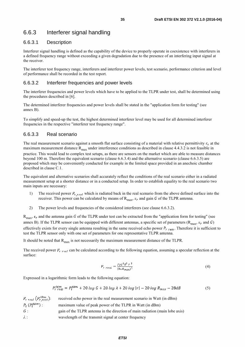
ETSI
Draft ETSI EN 302 372 V2.1.0 (2016-04) 35
6.6.3 Interferer signal handling
6.6.3.1 Description
Interferer signal handling is defined as the capability of the device to properly operate in coexistence with interferers in a defined frequency range without exceeding a given degradation due to the presence of an interfering input signal at the receiver.
The interferer test frequency range, interferers and interferer power levels, test scenario, performance criterion and level of performance shall be recorded in the test report.
6.6.3.2 Interferer frequencies and power levels
The interferer frequencies and power levels which have to be applied to the TLPR under test, shall be determined using the procedures described in [6].
The determined interferer frequencies and power levels shall be stated in the "application form for testing" (see annex B).
To simplify and speed-up the test, the highest determined interferer level may be used for all determined interferer frequencies in the respective "interferer test frequency range".
6.6.3.3 Real scenario
The real measurement scenario against a smooth flat surface consisting of a material with relative permittivity at the maximum measurement distance Rmax under interference conditions as described in clause 4.4.3.2 is not feasible in practice. This would lead to complex test setups, as there are sensors on the market which are able to measure distances beyond 100 m. Therefore the equivalent scenario (clause 6.6.3.4) and the alternative scenario (clause 6.6.3.5) are proposed which may be conveniently conducted for example in the limited space provided in an anechoic chamber described in clause C.1.
The equivalent and alternative scenarios shall accurately reflect the conditions of the real scenario either in a radiated measurement setup at a shorter distance or in a conducted setup. In order to establish equality to the real scenario two main inputs are necessary:
1) The received power _ which is radiated back in the real scenario from the above defined surface into the receiver. This power can be calculated by means of Rmax, and gain of the TLPR antenna.
2) The power levels and frequencies of the considered interferers (see clause 6.6.3.2).
Rmax, and the antenna gain of the TLPR under test can be extracted from the "application form for testing" (see annex B). If the TLPR sensor can be equipped with different antennas, a specific set of parameters (Rmax, and ) effectively exists for every single antenna resulting in the same received echo power _ . Therefore it is sufficient to test the TLPR sensor only with one set of parameters for one representative TLPR antenna.
It should be noted that Rmax is not necessarily the maximum measurement distance of the TLPR.
The received power _ can be calculated according to the following equation, assuming a specular reflection at the surface:
_ =*-
/||
123+4 (4)
Expressed in a logarithmic form leads to the following equation:
_ = + 20 + 20 + 20|| − 20 − 28 (5)
_ _ : received echo power in the real measurement scenario in Watt (in dBm) : maximum value of peak power of the TLPR in Watt (in dBm) : gain of the TLPR antenna in the direction of main radiation (main lobe axis) : wavelength of the transmit signal at center frequency
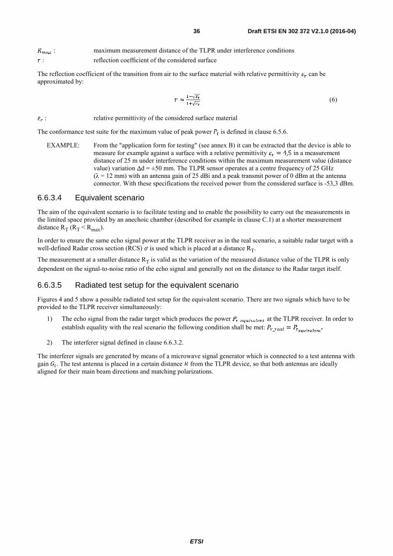
ETSI
Draft ETSI EN 302 372 V2.1.0 (2016-04) 36
: maximum measurement distance of the TLPR under interference conditions : reflection coefficient of the considered surface
The reflection coefficient of the transition from air to the surface material with relative permittivity can be approximated by:
≈#$√6 #7√6
(6)
: relative permittivity of the considered surface material
The conformance test suite for the maximum value of peak power is defined in clause 6.5.6.
EXAMPLE: From the "application form for testing" (see annex B) it can be extracted that the device is able to measure for example against a surface with a relative permittivity = 4,5 in a measurement distance of 25 m under interference conditions within the maximum measurement value (distance value) variation Δd = ±50 mm. The TLPR sensor operates at a centre frequency of 25 GHz (λ = 12 mm) with an antenna gain of 25 dBi and a peak transmit power of 0 dBm at the antenna connector. With these specifications the received power from the considered surface is -53,3 dBm.
6.6.3.4 Equivalent scenario
The aim of the equivalent scenario is to facilitate testing and to enable the possibility to carry out the measurements in the limited space provided by an anechoic chamber (described for example in clause C.1) at a shorter measurement distance RT (RT < Rmax).
In order to ensure the same echo signal power at the TLPR receiver as in the real scenario, a suitable radar target with a well-defined Radar cross section (RCS) is used which is placed at a distance RT.
The measurement at a smaller distance RT is valid as the variation of the measured distance value of the TLPR is only dependent on the signal-to-noise ratio of the echo signal and generally not on the distance to the Radar target itself.
6.6.3.5 Radiated test setup for the equivalent scenario
Figures 4 and 5 show a possible radiated test setup for the equivalent scenario. There are two signals which have to be provided to the TLPR receiver simultaneously:
1) The echo signal from the radar target which produces the power _ at the TLPR receiver. In order to establish equality with the real scenario the following condition shall be met: _ = .
2) The interferer signal defined in clause 6.6.3.2.
The interferer signals are generated by means of a microwave signal generator which is connected to a test antenna with gain. The test antenna is placed in a certain distance from the TLPR device, so that both antennas are ideally aligned for their main beam directions and matching polarizations.
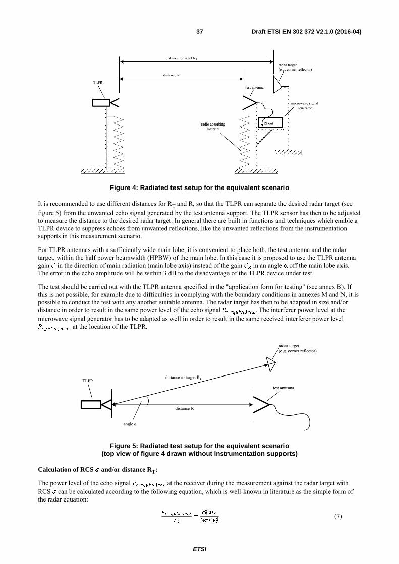
ETSI
Draft ETSI EN 302 372 V2.1.0 (2016-04) 37
Figure 4: Radiated test setup for the equivalent scenario
It is recommended to use different distances for RT and R, so that the TLPR can separate the desired radar target (see figure 5) from the unwanted echo signal generated by the test antenna support. The TLPR sensor has then to be adjusted to measure the distance to the desired radar target. In general there are built in functions and techniques which enable a TLPR device to suppress echoes from unwanted reflections, like the unwanted reflections from the instrumentation supports in this measurement scenario.
For TLPR antennas with a sufficiently wide main lobe, it is convenient to place both, the test antenna and the radar target, within the half power beamwidth (HPBW) of the main lobe. In this case it is proposed to use the TLPR antenna gain in the direction of main radiation (main lobe axis) instead of the gain ∝ in an angle α off the main lobe axis. The error in the echo amplitude will be within 3 dB to the disadvantage of the TLPR device under test.
The test should be carried out with the TLPR antenna specified in the "application form for testing" (see annex B). If this is not possible, for example due to difficulties in complying with the boundary conditions in annexes M and N, it is possible to conduct the test with any another suitable antenna. The radar target has then to be adapted in size and/or distance in order to result in the same power level of the echo signal_. The interferer power level at the microwave signal generator has to be adapted as well in order to result in the same received interferer power level _ at the location of the TLPR.
Figure 5: Radiated test setup for the equivalent scenario (top view of figure 4 drawn without instrumentation supports)
Calculation of RCS and/or distance RT:
The power level of the echo signal _ at the receiver during the measurement against the radar target with RCS can be calculated according to the following equation, which is well-known in literature as the simple form of the radar equation:
* _
*=-∝/9
1:34+ (7)
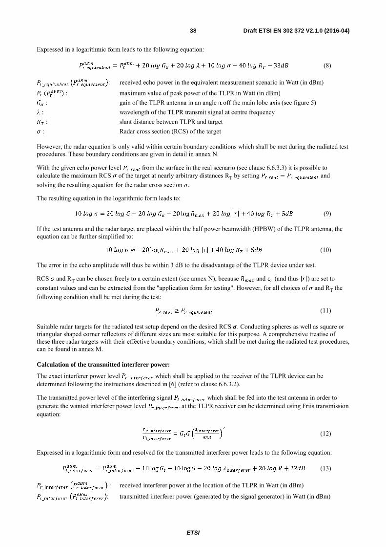
ETSI
Draft ETSI EN 302 372 V2.1.0 (2016-04) 38
Expressed in a logarithmic form leads to the following equation:
_ = + 20 + 20 + 10 − 40 − 33 (8)
__ : received echo power in the equivalent measurement scenario in Watt (in dBm)
: maximum value of peak power of the TLPR in Watt (in dBm) : gain of the TLPR antenna in an angle α off the main lobe axis (see figure 5) : wavelength of the TLPR transmit signal at centre frequency : slant distance between TLPR and target : Radar cross section (RCS) of the target
However, the radar equation is only valid within certain boundary conditions which shall be met during the radiated test procedures. These boundary conditions are given in detail in annex N.
With the given echo power level _ from the surface in the real scenario (see clause 6.6.3.3) it is possible to calculate the maximum RCS of the target at nearly arbitrary distances RT by setting _ = _ and solving the resulting equation for the radar cross section .
The resulting equation in the logarithmic form leads to:
10 = 20 − 20 − 20 log + 20|| + 40 + 5 (9)
If the test antenna and the radar target are placed within the half power beamwidth (HPBW) of the TLPR antenna, the equation can be further simplified to:
10 ≈ −20 log + 20|| + 40 + 5 (10)
The error in the echo amplitude will thus be within 3 dB to the disadvantage of the TLPR device under test.
RCS and RT can be chosen freely to a certain extent (see annex N), because and (and thus ||) are set to constant values and can be extracted from the "application form for testing". However, for all choices of and RT the following condition shall be met during the test:
_ ≥ _ (11)
Suitable radar targets for the radiated test setup depend on the desired RCS . Conducting spheres as well as square or triangular shaped corner reflectors of different sizes are most suitable for this purpose. A comprehensive treatise of these three radar targets with their effective boundary conditions, which shall be met during the radiated test procedures, can be found in annex M.
Calculation of the transmitted interferer power:
The exact interferer power level _ which shall be applied to the receiver of the TLPR device can be determined following the instructions described in [6] (refer to clause 6.6.3.2).
The transmitted power level of the interfering signal _ which shall be fed into the test antenna in order to generate the wanted interferer power level _ at the TLPR receiver can be determined using Friis transmission equation:
* _
*_ = !
/
:3+"% (12)
Expressed in a logarithmic form and resolved for the transmitted interferer power leads to the following equation:
_ = _ − 10 log − 10 log − 20 + 20 + 22 (13)
_ _ : received interferer power at the location of the TLPR in Watt (in dBm)
_ _ : transmitted interferer power (generated by the signal generator) in Watt (in dBm)
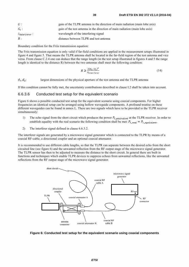
ETSI
Draft ETSI EN 302 372 V2.1.0 (2016-04) 39
: gain of the TLPR antenna in the direction of main radiation (main lobe axis) : gain of the test antenna in the direction of main radiation (main lobe axis) : wavelength of the interfering signal : distance between TLPR and test antenna
Boundary condition for the Friis transmission equation:
The Friis transmission equation is only valid if far-field conditions are applied in the measurement setups illustrated in figure 4 and figure 5. That means the TLPR antenna shall be located in the far-field region of the test antenna and vice versa. From clause C.2.4 one can deduce that the range length (in the test setup illustrated in figures 4 and 5 the range length is identical to the distance R) between the two antennas shall meet the following condition:
≥%174
/ (14)
#,%: largest dimensions of the physical aperture of the test antenna and the TLPR antenna
If this condition cannot be fully met, the uncertainty contributions described in clause I.2 shall be taken into account.
6.6.3.6 Conducted test setup for the equivalent scenario
Figure 6 shows a possible conducted test setup for the equivalent scenario using coaxial components. For higher frequencies an identical setup can be arranged using hollow waveguide components. A profound treatise on these different waveguides can be found in annex L. There are two signals which have to be provided to the TLPR receiver simultaneously:
1) The echo signal from the short circuit which produces the power _ at the TLPR receiver. In order to establish equality with the real scenario the following condition shall be met: _ = _.
2) The interferer signal defined in clause 6.6.3.2.
The interferer signals are generated by a microwave signal generator which is connected to the TLPR by means of a coaxial RF-cable, a directional coupler and an optional coaxial attenuator.
It is recommended to use different cable lengths, so that the TLPR can separate between the desired echo from the short circuited line (see figure 6) and the unwanted reflection from the RF output stage of the microwave signal generator. The TLPR sensor has then to be adjusted to measure the distance to the short circuit. In general there are built in functions and techniques which enable TLPR devices to suppress echoes from unwanted reflections, like the unwanted reflections from the RF output stage of the microwave signal generator.
Figure 6: Conducted test setup for the equivalent scenario using coaxial components
ETSI
Draft ETSI EN 302 372 V2.1.0 (2016-04) 40
Calculation of the required echo attenuation:
The power level of the echo signal _ at the TLPR receiver during the measurement against the short circuit can be calculated according to the following equation:
_ = − 2 !" (#$%) + !'_( + _( (15)
_ : received echo power in the equivalent measurement scenario in dBm
: maximum value of peak power of the TLPR in dBm !" (#$%) : coupling loss of the directional coupler between ports 1 and 2 in dB
!'_( : cable loss of coaxial RF-cable A in dB _( : attenuation of the coaxial attenuator A in dB
The three different loss contributions are assumed to be inserted in positive dB-values in equation (15) above.
With the given echo power level _ from the surface in the real scenario (refer to clause 6.6.3.3) it is possible to calculate the required attenuation of the coaxial attenuator A by setting _ = _ and solving the resulting equation for the additional attenuation _( .
For all choices of the attenuations in the signal path from the TLPR to the short circuit, the following condition shall be met during the test:
_ ≥ _ (16)
Calculation of the transmitted interferer power:
The exact interferer power level _ which shall be applied to the receiver of the TLPR device can be determined following the instructions described in ETSI TS 103 361 [6] (refer to clause 6.6.3.2).
The transmitted power level of the interfering signal _ which shall be fed into coaxial cable B at the RF-connector of the signal generator in order to generate the wanted interferer power level _ at the TLPR receiver can be determined using the following equation:
= _ + !" 1#$&4 + !' + _ (17)
_ : received interferer power at the TLPR receiver in dBm
: transmitted interferer power (generated by the signal generator) in dBm
!" (#$&) : coupling loss of the directional coupler between ports 1 and 3 in dB
!'_ : cable loss of coaxial RF-cable B in dB _ : attenuation of the coaxial attenuator B in dB
The different loss contributions are assumed to be inserted in positive dB-values in the equation above.
6.6.3.7 Test procedure for the equivalent scenario
The test for interferer signal handling using the equivalent scenario shall be conducted as follows:
• The interferer frequencies # and power levels _ are determined according to clause 6.6.3.2. The transmitted interferer power levels (microwave signal generator output power) _ can be determined by means of the methods described in clause 6.6.3.5 for the radiated test setup or clause 6.6.3.6 for the conducted test setup.
• With the specifications of Rmax, and antenna gain of the TLPR under test in the "application form for testing", the radar cross section (RCS) of the radar target and the distance RT can be determined according to clause 6.6.3.5 for the radiated setup.
ETSI
Draft ETSI EN 302 372 V2.1.0 (2016-04) 41
For the conducted setup in clause 6.6.3.6 first the received echo power _ shall be determined according to clause 6.6.3.3. Then the required attenuation in the signal path of the TLPR can be calculated following the instructions in clause 6.6.3.6.
• The measurement setup for the equivalent scenario is arranged according to the figures 4 and 5 in clause 6.6.3.5 with a suitable radar target for the radiated approach. For the conducted approach the measurement setup is arranged according to figure 6 in clause 6.6.3.6.
The resulting received echo power _ shall be equal or less than the received echo power _ in the real scenario.
• The distance measurement is carried out against the radar target in the radiated setup (see figures 4 and 5) or against the short circuit in the conducted setup (see figure 6) with the interferer turned on.
The test is passed if the measured distance value stays within the maximum measurement value variation Δd (see clause 4.4.3.3). The test shall be conducted over at least a time period of 120 seconds or 40 times the step response time of the TLPR sensor, whichever is longer.
During this test the TLPR sensor shall be configured for the fastest possible step response time. Therefore all averaging functions and echo holding techniques shall be deactivated. If a complete deactivation of these functions is not possible, they shall be set to a state which ensures the fastest possible step response time. The configuration of the device under test in this case shall be noted in the test report.
• If the step response of the TLPR sensor is not known, it can be estimated by introducing a sudden change of the distance to the target in the radiated setup or the short circuit in the conducted setup, respectively. The step response time is the time span until the new distance value reaches 90 % of the final value.
• Attention has to be paid that the correct echo is tracked by the TLPR device during the test. This shall be verified by switching off the interferer signal. In this case the distance value shall also stay inside the maximum measurement value variation Δd.
• The test shall be repeated for all determined interferers.
6.6.3.8 Alternative scenario
The aim of the alternative scenario (in comparison to the equivalent scenario in clause 6.6.3.4) is to further facilitate testing and to enable the possibility to carry out the measurements in the limited space provided by an anechoic chamber (described for example in clause C.1) without the need for a simultaneous distance measurement. The interfering signal is directly coupled into the receiver and the response of the noise floor of the TLPR device is monitored.
For applying this alternative scenario it is mandatory that the TLPR provides the possibility to access and monitor its noise level for example in an echo curve graph. If the sensor under test does not provide this feature the equivalent scenario in clause 6.6.3.4 has to be applied for testing.
The TLPR signal processing algorithms need a stable echo and a minimum echo signal-to-noise ratio SNRmin to ensure a measurement value variation Δd ≤ ±50 mm over time during a distance measurement. Echoes with smaller signal-to-noise ratios than SNRmin cannot be reliably processed by the TLPR with the defined accuracy. This relation can be used to define a further test scenario which is equivalent to the scenario described in clause 6.6.3.4.
The interferer will cause a rise of the noise floor in the receiver of the TLPR sensor, no matter what frequency or type of modulation is used in the interfering signal. Thus a degradation of the SNR of a simultaneously measured echo signal will arise. If the noise floor of the receiver stays at least an amount of SNRmin below the power level of the echo signal _ produced by the flat surface (see clause 6.6.3.3), a measurement variation of Δd ≤ ±50 mm can be assured.
The manufacturer shall supply the relation between the measurement value variation Δd ≤ ±50 mm and the minimum required signal-to-noise-ratio SNRmin for the individual TLPR under test. This can preferably be achieved by providing recorded measurement data. The minimum required signal-to-noise-ratio SNRmin shall be noted in the "application form for testing" (refer to annex B).
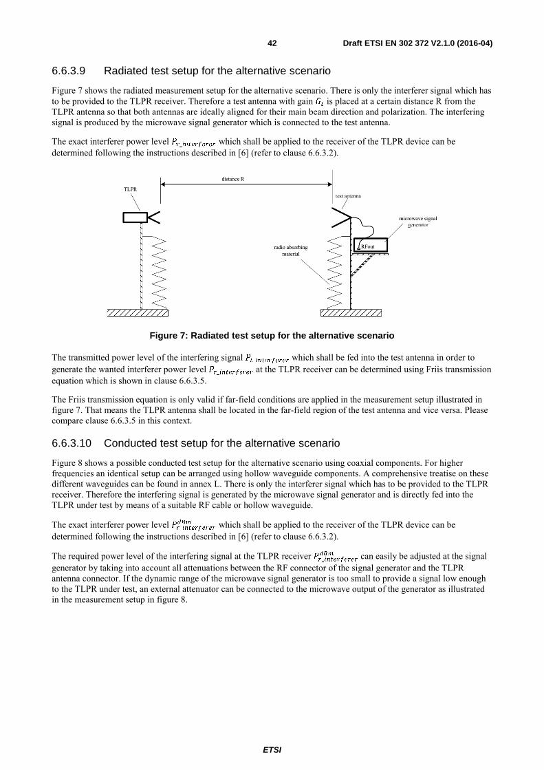
ETSI
Draft ETSI EN 302 372 V2.1.0 (2016-04) 42
6.6.3.9 Radiated test setup for the alternative scenario
Figure 7 shows the radiated measurement setup for the alternative scenario. There is only the interferer signal which has to be provided to the TLPR receiver. Therefore a test antenna with gain is placed at a certain distance R from the TLPR antenna so that both antennas are ideally aligned for their main beam direction and polarization. The interfering signal is produced by the microwave signal generator which is connected to the test antenna.
The exact interferer power level _ which shall be applied to the receiver of the TLPR device can be determined following the instructions described in [6] (refer to clause 6.6.3.2).
Figure 7: Radiated test setup for the alternative scenario
The transmitted power level of the interfering signal _ which shall be fed into the test antenna in order to generate the wanted interferer power level _ at the TLPR receiver can be determined using Friis transmission equation which is shown in clause 6.6.3.5.
The Friis transmission equation is only valid if far-field conditions are applied in the measurement setup illustrated in figure 7. That means the TLPR antenna shall be located in the far-field region of the test antenna and vice versa. Please compare clause 6.6.3.5 in this context.
6.6.3.10 Conducted test setup for the alternative scenario
Figure 8 shows a possible conducted test setup for the alternative scenario using coaxial components. For higher frequencies an identical setup can be arranged using hollow waveguide components. A comprehensive treatise on these different waveguides can be found in annex L. There is only the interferer signal which has to be provided to the TLPR receiver. Therefore the interfering signal is generated by the microwave signal generator and is directly fed into the TLPR under test by means of a suitable RF cable or hollow waveguide.
The exact interferer power level _ which shall be applied to the receiver of the TLPR device can be determined following the instructions described in [6] (refer to clause 6.6.3.2).
The required power level of the interfering signal at the TLPR receiver _ can easily be adjusted at the signal generator by taking into account all attenuations between the RF connector of the signal generator and the TLPR antenna connector. If the dynamic range of the microwave signal generator is too small to provide a signal low enough to the TLPR under test, an external attenuator can be connected to the microwave output of the generator as illustrated in the measurement setup in figure 8.
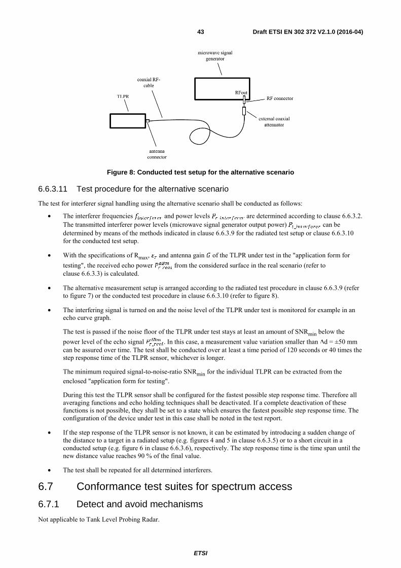
ETSI
Draft ETSI EN 302 372 V2.1.0 (2016-04) 43
Figure 8: Conducted test setup for the alternative scenario
6.6.3.11 Test procedure for the alternative scenario
The test for interferer signal handling using the alternative scenario shall be conducted as follows:
• The interferer frequencies # and power levels _ are determined according to clause 6.6.3.2. The transmitted interferer power levels (microwave signal generator output power) _ can be determined by means of the methods indicated in clause 6.6.3.9 for the radiated test setup or clause 6.6.3.10 for the conducted test setup.
• With the specifications of Rmax, and antenna gain of the TLPR under test in the "application form for testing", the received echo power _ from the considered surface in the real scenario (refer to clause 6.6.3.3) is calculated.
• The alternative measurement setup is arranged according to the radiated test procedure in clause 6.6.3.9 (refer to figure 7) or the conducted test procedure in clause 6.6.3.10 (refer to figure 8).
• The interfering signal is turned on and the noise level of the TLPR under test is monitored for example in an echo curve graph.
The test is passed if the noise floor of the TLPR under test stays at least an amount of SNRmin below the power level of the echo signal _ . In this case, a measurement value variation smaller than Δd = ±50 mm can be assured over time. The test shall be conducted over at least a time period of 120 seconds or 40 times the step response time of the TLPR sensor, whichever is longer.
The minimum required signal-to-noise-ratio SNRmin for the individual TLPR can be extracted from the enclosed "application form for testing".
During this test the TLPR sensor shall be configured for the fastest possible step response time. Therefore all averaging functions and echo holding techniques shall be deactivated. If a complete deactivation of these functions is not possible, they shall be set to a state which ensures the fastest possible step response time. The configuration of the device under test in this case shall be noted in the test report.
• If the step response of the TLPR sensor is not known, it can be estimated by introducing a sudden change of the distance to a target in a radiated setup (e.g. figures 4 and 5 in clause 6.6.3.5) or to a short circuit in a conducted setup (e.g. figure 6 in clause 6.6.3.6), respectively. The step response time is the time span until the new distance value reaches 90 % of the final value.
• The test shall be repeated for all determined interferers.
6.7 Conformance test suites for spectrum access
6.7.1 Detect and avoid mechanisms
Not applicable to Tank Level Probing Radar.
ETSI
Draft ETSI EN 302 372 V2.1.0 (2016-04) 44
6.7.2 Listen before talk
Not applicable to Tank Level Probing Radar.
6.7.3 Low duty cycle
Not applicable to Tank Level Probing Radar.
6.8 Conformance test suites for antenna requirements Not applicable to Tank Level Probing Radar.
6.9 Other test suites
6.9.1 Adaptive power control (APC)
Not applicable to Tank Level Probing Radar.
6.9.2 Activity factor and duty cycle
The activity factor (AF) is under control of the user, determined by the users transmission time and is normally declared by the user or applicant. The provider shall declare the activity factor and the respective activity factor category for the DUT. This declaration shall be stated in the test report.
The duty cycle (DC) is determined by the transmitters’ modulation type and shall be measured by means of a diode detector and an oscilloscope or another appropriate instrument. The duty cycle (DC) is important when the radiated power is measured and the modulation cannot be switched off. This is specifically the case when the equipment is using a pulsed type of modulation:
• Using suitable attenuators, the output power of the transmitter shall be coupled to a matched diode detector. The output of the matched diode detector shall be connected to the vertical channel of an oscilloscope.
• The combination of the matched diode detector and the oscilloscope shall be capable of faithfully reproducing the envelope peaks and the duty cycle of the transmitter output signal.
• The observed duty cycle of the transmitter (tpulse/(PRI)) shall be noted as DC (0 < DC ≤ 100 %), and recorded in the test report. For the purpose of testing, the equipment shall be operated with a duty cycle that is equal to or greater than 10 %. Where this duty cycle is not possible, then this shall be stated on the test report and the actual duty cycle shall be declared.
6.9.3 Frequency domain mitigation
Declared by manufacturer.
6.9.4 Shielding effects
The installation requirements of Tank Level Probing Radar equipment to ensure a proper shielding can be found in annex E.
6.9.5 Thermal radiations
Not applicable to Tank Level Probing Radar.
6.9.6 Site registration
Not applicable to Tank Level Probing Radar.
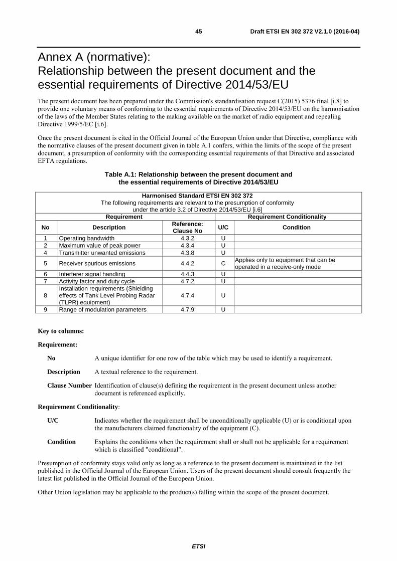
ETSI
Draft ETSI EN 302 372 V2.1.0 (2016-04) 45
Annex A (normative): Relationship between the present document and the essential requirements of Directive 2014/53/EU The present document has been prepared under the Commission's standardisation request C(2015) 5376 final [i.8] to provide one voluntary means of conforming to the essential requirements of Directive 2014/53/EU on the harmonisation of the laws of the Member States relating to the making available on the market of radio equipment and repealing Directive 1999/5/EC [i.6].
Once the present document is cited in the Official Journal of the European Union under that Directive, compliance with the normative clauses of the present document given in table A.1 confers, within the limits of the scope of the present document, a presumption of conformity with the corresponding essential requirements of that Directive and associated EFTA regulations.
Table A.1: Relationship between the present document and the essential requirements of Directive 2014/53/EU
Harmonised Standard ETSI EN 302 372 The following requirements are relevant to the presumption of conformity
under the article 3.2 of Directive 2014/53/EU [i.6] Requirement Requirement Conditionality
No Description Reference: Clause No U/C Condition
1 Operating bandwidth 4.3.2 U 2 Maximum value of peak power 4.3.4 U 4 Transmitter unwanted emissions 4.3.8 U
5 Receiver spurious emissions 4.4.2 C Applies only to equipment that can be operated in a receive-only mode
6 Interferer signal handling 4.4.3 U 7 Activity factor and duty cycle 4.7.2 U
8 Installation requirements (Shielding effects of Tank Level Probing Radar (TLPR) equipment)
4.7.4 U
9 Range of modulation parameters 4.7.9 U
Key to columns:
Requirement:
No A unique identifier for one row of the table which may be used to identify a requirement.
Description A textual reference to the requirement.
Clause Number Identification of clause(s) defining the requirement in the present document unless another document is referenced explicitly.
Requirement Conditionality:
U/C Indicates whether the requirement shall be unconditionally applicable (U) or is conditional upon the manufacturers claimed functionality of the equipment (C).
Condition Explains the conditions when the requirement shall or shall not be applicable for a requirement which is classified "conditional".
Presumption of conformity stays valid only as long as a reference to the present document is maintained in the list published in the Official Journal of the European Union. Users of the present document should consult frequently the latest list published in the Official Journal of the European Union.
Other Union legislation may be applicable to the product(s) falling within the scope of the present document.
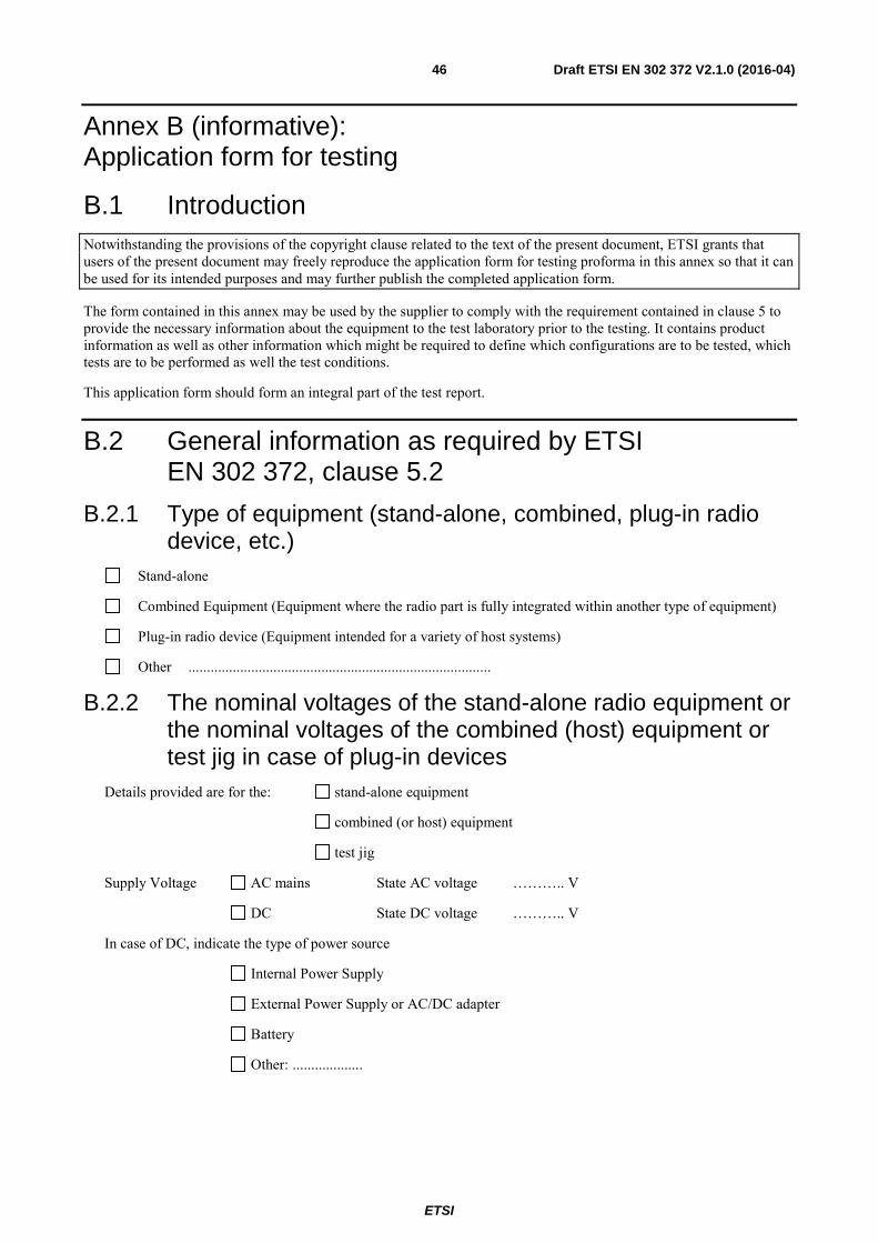
ETSI
Draft ETSI EN 302 372 V2.1.0 (2016-04) 46
Annex B (informative): Application form for testing
B.1 Introduction Notwithstanding the provisions of the copyright clause related to the text of the present document, ETSI grants that users of the present document may freely reproduce the application form for testing proforma in this annex so that it can be used for its intended purposes and may further publish the completed application form.
The form contained in this annex may be used by the supplier to comply with the requirement contained in clause 5 to provide the necessary information about the equipment to the test laboratory prior to the testing. It contains product information as well as other information which might be required to define which configurations are to be tested, which tests are to be performed as well the test conditions.
This application form should form an integral part of the test report.
B.2 General information as required by ETSI EN 302 372, clause 5.2
B.2.1 Type of equipment (stand-alone, combined, plug-in radio device, etc.)
Stand-alone
Combined Equipment (Equipment where the radio part is fully integrated within another type of equipment)
Plug-in radio device (Equipment intended for a variety of host systems)
Other ..................................................................................
B.2.2 The nominal voltages of the stand-alone radio equipment or the nominal voltages of the combined (host) equipment or test jig in case of plug-in devices
Details provided are for the: stand-alone equipment
combined (or host) equipment
test jig
Supply Voltage AC mains State AC voltage ……….. V
DC State DC voltage ……….. V
In case of DC, indicate the type of power source
Internal Power Supply
External Power Supply or AC/DC adapter
Battery
Other: ...................
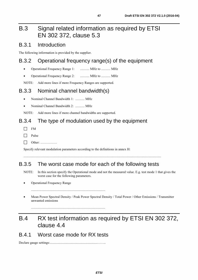
ETSI
Draft ETSI EN 302 372 V2.1.0 (2016-04) 47
B.3 Signal related information as required by ETSI EN 302 372, clause 5.3
B.3.1 Introduction The following information is provided by the supplier.
B.3.2 Operational frequency range(s) of the equipment • Operational Frequency Range 1: ........... MHz to ........... MHz
• Operational Frequency Range 2: ........... MHz to ........... MHz
NOTE: Add more lines if more Frequency Ranges are supported.
B.3.3 Nominal channel bandwidth(s) • Nominal Channel Bandwidth 1: ........... MHz
• Nominal Channel Bandwidth 2: ........... MHz
NOTE: Add more lines if more channel bandwidths are supported.
B.3.4 The type of modulation used by the equipment FM
Pulse
Other: ……………
Specify relevant modulation parameters according to the definitions in annex H:
.....................................................................................................................................................................
B.3.5 The worst case mode for each of the following tests NOTE: In this section specify the Operational mode and not the measured value. E.g. test mode 1 that gives the
worst case for the following parameters.
• Operational Frequency Range
.........................................................................................
• Mean Power Spectral Density / Peak Power Spectral Density / Total Power / Other Emissions / Transmitter unwanted emissions
.........................................................................................
B.4 RX test information as required by ETSI EN 302 372, clause 4.4
B.4.1 Worst case mode for RX tests Declare gauge settings:.........................................................……..

ETSI
Draft ETSI EN 302 372 V2.1.0 (2016-04) 48
B.4.2 Performance criterion and level of performance • performance criterion: distance value variation Δd over time.
• level of performance: ....................................(max limit Δd ≤ ±50 mm).
The performance criterion and the level of performance shall also be stated in the user manual.
B.4.3 RX test setup Specify which test setup is used under clause 6.6.3:
................................................................................................................................
• Declaration of the parameters in the real scenario (clause 6.6.3.3):
Maximum measurement distance under interference conditions Rmax: ...........m
Surface material with relative permittivity: ...........
Considered antenna type: ................................. with gain: ...........dBi
• Declaration of the parameter in the alternative scenario (clause 6.6.3.8):
Minimum required signal-to-noise-ratio SNRmin: ...........dB
B.4.4 Definition of interfering signals The list of the three worst-case interferers is chosen from [6].
Frequency [MHz] Power [dBm] Type of signal (e.g. CW, CW with DC, other modulation)
B.5 Information on mitigation techniques as required by ETSI EN 302 372, clause 4.7
B.5.1 Mitigation techniques The inclusion and any necessary implementation details of any mitigation or equivalent mitigation techniques shall be declared.
APC
Range of power level variation:.......................................................................................................
Activity factor and duty cycle
Specify..............................................................................................................................................
Frequency domain mitigation
Specify...............................................................................................................................................
Shielding effects
Specify...............................................................................................................................................
Site registration
ETSI
Draft ETSI EN 302 372 V2.1.0 (2016-04) 49
Specify............................................................................................................................................... Equivalent mitigation techniques
Specify...............................................................................................................................................
Others
Specify……………………...............................................................................................................
B.6 Additional information provided by the applicant
B.6.1 About the equipment under test The equipment submitted are representative production models
If not, the equipment submitted are pre-production models?
If pre-production equipment are submitted, the final production equipment will be identical in all radio related respects with the equipment tested
If not, supply full details
..................................................................................
..................................................................................
The equipment submitted is CE marked
In addition to the CE mark, the Class-II identifier (Alert Sign) is affixed
B.6.2 Additional items and/or supporting equipment provided Spare batteries (e.g. for portable equipment)
Battery charging device
External Power Supply or AC/DC adapter
Test Jig or interface box
RF test fixture (for equipment with integrated antennas)
Host System Manufacturer: ....................
Model #: ....................
Model name: ....................
Combined equipment Manufacturer: ....................
Model #: ....................
Model name: ....................
User Manual
Technical documentation (Handbook and circuit diagrams)
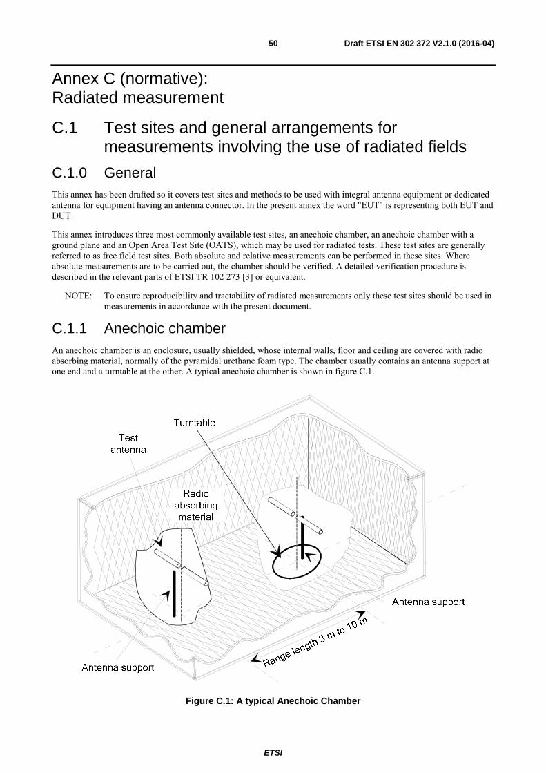
ETSI
Draft ETSI EN 302 372 V2.1.0 (2016-04) 50
Annex C (normative): Radiated measurement
C.1 Test sites and general arrangements for measurements involving the use of radiated fields
C.1.0 General This annex has been drafted so it covers test sites and methods to be used with integral antenna equipment or dedicated antenna for equipment having an antenna connector. In the present annex the word "EUT" is representing both EUT and DUT.
This annex introduces three most commonly available test sites, an anechoic chamber, an anechoic chamber with a ground plane and an Open Area Test Site (OATS), which may be used for radiated tests. These test sites are generally referred to as free field test sites. Both absolute and relative measurements can be performed in these sites. Where absolute measurements are to be carried out, the chamber should be verified. A detailed verification procedure is described in the relevant parts of ETSI TR 102 273 [3] or equivalent.
NOTE: To ensure reproducibility and tractability of radiated measurements only these test sites should be used in measurements in accordance with the present document.
C.1.1 Anechoic chamber An anechoic chamber is an enclosure, usually shielded, whose internal walls, floor and ceiling are covered with radio absorbing material, normally of the pyramidal urethane foam type. The chamber usually contains an antenna support at one end and a turntable at the other. A typical anechoic chamber is shown in figure C.1.
Figure C.1: A typical Anechoic Chamber
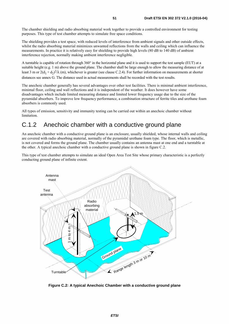
ETSI
Draft ETSI EN 302 372 V2.1.0 (2016-04) 51
The chamber shielding and radio absorbing material work together to provide a controlled environment for testing purposes. This type of test chamber attempts to simulate free space conditions.
The shielding provides a test space, with reduced levels of interference from ambient signals and other outside effects, whilst the radio absorbing material minimizes unwanted reflections from the walls and ceiling which can influence the measurements. In practice it is relatively easy for shielding to provide high levels (80 dB to 140 dB) of ambient interference rejection, normally making ambient interference negligible.
A turntable is capable of rotation through 360° in the horizontal plane and it is used to support the test sample (EUT) at a suitable height (e.g. 1 m) above the ground plane. The chamber shall be large enough to allow the measuring distance of at least 3 m or 2(d1 + d2)2/λ (m), whichever is greater (see clause C.2.4). For further information on measurements at shorter distances see annex G. The distance used in actual measurements shall be recorded with the test results.
The anechoic chamber generally has several advantages over other test facilities. There is minimal ambient interference, minimal floor, ceiling and wall reflections and it is independent of the weather. It does however have some disadvantages which include limited measuring distance and limited lower frequency usage due to the size of the pyramidal absorbers. To improve low frequency performance, a combination structure of ferrite tiles and urethane foam absorbers is commonly used.
All types of emission, sensitivity and immunity testing can be carried out within an anechoic chamber without limitation.
C.1.2 Anechoic chamber with a conductive ground plane An anechoic chamber with a conductive ground plane is an enclosure, usually shielded, whose internal walls and ceiling are covered with radio absorbing material, normally of the pyramidal urethane foam type. The floor, which is metallic, is not covered and forms the ground plane. The chamber usually contains an antenna mast at one end and a turntable at the other. A typical anechoic chamber with a conductive ground plane is shown in figure C.2.
This type of test chamber attempts to simulate an ideal Open Area Test Site whose primary characteristic is a perfectly conducting ground plane of infinite extent.
Turntable
Testantenna
Antennamast
Radioabsorbingmaterial
Range length 3 m or 10 m
1,5 m
1 m
to 4
m
Ground plane
Figure C.2: A typical Anechoic Chamber with a conductive ground plane

ETSI
Draft ETSI EN 302 372 V2.1.0 (2016-04) 52
In this facility the ground plane creates the wanted reflection path, such that the signal received by the receiving antenna is the sum of the signals from both the direct and reflected transmission paths. This creates a unique received signal level for each height of the transmitting antenna (or EUT) and the receiving antenna above the ground plane.
The antenna mast provides a variable height facility (from 1 m to 4 m) so that the position of the test antenna can be optimized for maximum coupled signal between antennas or between an EUT and the test antenna.
A turntable is capable of rotation through 360° in the horizontal plane and it is used to support the test sample (EUT) at a specified height, usually 1,5 m above the ground plane. The chamber shall be large enough to allow the measuring distance of at least 3 m or 2(d1 + d2)2/λ (m), whichever is greater (see clause C.2.4). For further information on measurements at shorter distances see annex G. The distance used in actual measurements shall be recorded with the test results.
Emission testing involves firstly "peaking" the field strength from the EUT by raising and lowering the receiving antenna on the mast (to obtain the maximum constructive interference of the direct and reflected signals from the EUT) and then rotating the turntable for a "peak" in the azimuth plane. At this height of the test antenna on the mast, the amplitude of the received signal is noted. Secondly the EUT is replaced by a substitution antenna (positioned at the EUT's phase or volume centre) which is connected to a signal generator. The signal is again "peaked" and the signal generator output adjusted until the level, noted in stage one, is again measured on the receiving device.
Receiver sensitivity tests over a ground plane also involve "peaking" the field strength by raising and lowering the test antenna on the mast to obtain the maximum constructive interference of the direct and reflected signals, this time using a measuring antenna which has been positioned where the phase or volume centre of the EUT will be during testing. A transform factor is derived. The test antenna remains at the same height for stage two, during which the measuring antenna is replaced by the EUT. The amplitude of the transmitted signal is reduced to determine the field strength level at which a specified response is obtained from the EUT.
C.1.3 Open area test site (OATS) An Open Area Test Site comprises a turntable at one end and an antenna mast of variable height at the other end above a ground plane, which in the ideal case, is perfectly conducting and of infinite extent. In practice, whilst good conductivity can be achieved, the ground plane size has to be limited. A typical OATS is shown in figure C.3.
Range length 3 or 10 m
Turntable
Ground plane
Dipole antennas
Antenna mast
Figure C.3: A typical Open Area Test Site
The ground plane creates a wanted reflection path, such that the signal received by the receiving antenna is the sum of the signals received from the direct and reflected transmission paths. The phasing of these two signals creates a unique received level for each height of the transmitting antenna (or EUT) and the receiving antenna above the ground plane.

ETSI
Draft ETSI EN 302 372 V2.1.0 (2016-04) 53
Site qualification concerning antenna positions, turntable, measurement distance and other arrangements are same as for anechoic chamber with a ground plane. In radiated measurements an OATS is also used by the same way as anechoic chamber with a ground plane.
Typical measuring arrangement common for ground plane test sites is presented in the figure C.4.
Figure C.4: Measuring arrangement on ground plane test site (OATS set-up for spurious emission testing)
C.1.4 Minimum requirements for test sites for measurements above 18 GHz
Generally the test site shall be adequate to allow for testing in the far field of the EUT. The test site should therefore consist of an electromagnetic anechoic room where either at least the ground surface is covered with radio absorbing material or up to six surrounding surfaces are covered with radio absorbing material. The absorbing material shall have a minimum attenuation of 30 dB. It shall be verified that reflections are sufficiently reduced. The test site shall have the following dimensions:
• Width of 2 metres.
• Length of 3 metres.
• Height of 2 metres (only applicable for a room with more than one reflecting surface).
Highly directional receiving antennas help in reducing reflections. The use of standard gain horn antennas is recommended. It shall be noted that if the antenna aperture is smaller than the EUT, sufficient measurements in both azimuth and elevation shall be conducted in order to ensure that the maximum radiation is determined.
The measuring distance shall be selected in such way that antenna coupling effects are avoided. A distance of at least 0,5 m is therefore recommended. The EUT may be positioned at any height that minimizes reflections from the floor.
Due to high loss of coaxial cables at higher frequencies, the connection from the receiving antenna to the measuring receiver should not exceed 1 m, thus making it necessary to place the measuring receiver very close. This is especially the case when using external harmonic mixers with very short connections to the measuring receiver. Therefore the measuring receiver should somehow be covered with radio absorbing material in direction to the measuring field in order to reduce reflections. Figure C.5 shows an example of a test site above 18 GHz with one reflecting surface.
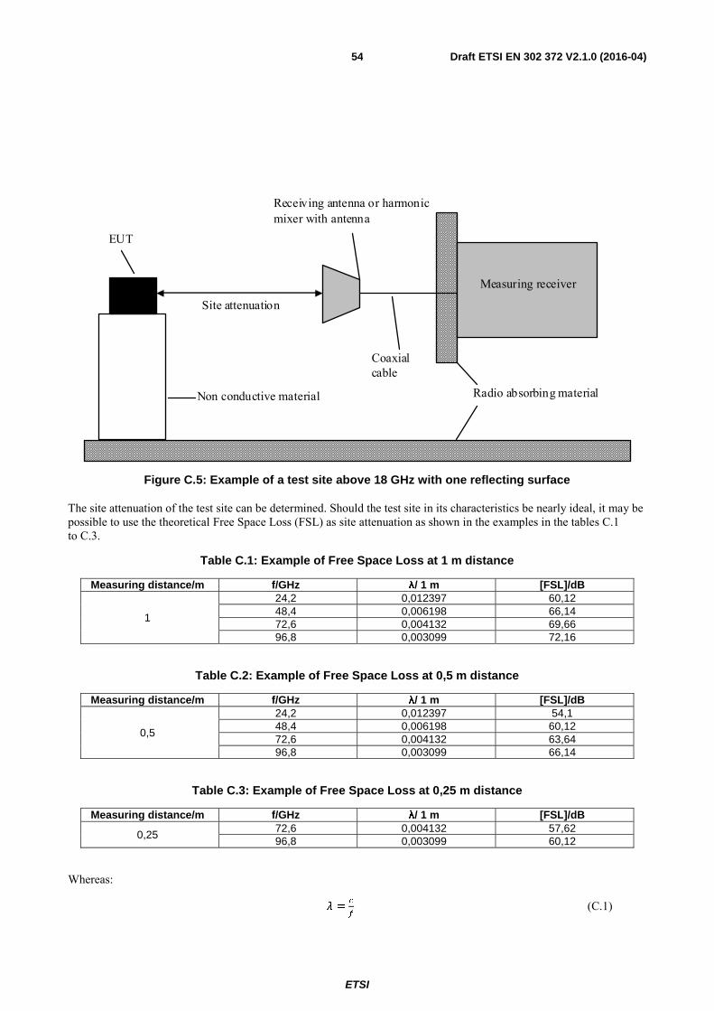
ETSI
Draft ETSI EN 302 372 V2.1.0 (2016-04) 54
Receiving antenna or harmonic mixer with antenna
Measuring receiver
Radio absorbing material
EUT
Non conductive material
Coaxial cable
Site attenuation
Figure C.5: Example of a test site above 18 GHz with one reflecting surface
The site attenuation of the test site can be determined. Should the test site in its characteristics be nearly ideal, it may be possible to use the theoretical Free Space Loss (FSL) as site attenuation as shown in the examples in the tables C.1 to C.3.
Table C.1: Example of Free Space Loss at 1 m distance
Measuring distance/m f/GHz λ/ 1 m [FSL]/dB
1
24,2 0,012397 60,12 48,4 0,006198 66,14 72,6 0,004132 69,66 96,8 0,003099 72,16
Table C.2: Example of Free Space Loss at 0,5 m distance
Measuring distance/m f/GHz λ/ 1 m [FSL]/dB
0,5
24,2 0,012397 54,1 48,4 0,006198 60,12 72,6 0,004132 63,64 96,8 0,003099 66,14
Table C.3: Example of Free Space Loss at 0,25 m distance
Measuring distance/m f/GHz λ/ 1 m [FSL]/dB
0,25 72,6 0,004132 57,62 96,8 0,003099 60,12
Whereas:
=!
(C.1)

ETSI
Draft ETSI EN 302 372 V2.1.0 (2016-04) 55
$% = 20 !:3/" (C.2)
C.1.5 Test antenna A test antenna is always used in radiated test methods. In emission tests (i.e. frequency error, effective radiated power, spurious emissions and adjacent channel power) the test antenna is used to detect the field from the EUT in one stage of the measurement and from the substitution antenna in the other stage. When the test site is used for the measurement of receiver characteristics (i.e. sensitivity and various immunity parameters) the antenna is used as the transmitting device.
The test antenna should be mounted on a support capable of allowing the antenna to be used in either horizontal or vertical polarization which, on ground plane sites (i.e. anechoic chambers with ground planes and Open Area Test Sites), should additionally allow the height of its centre above the ground to be varied over the specified range (usually 1 metre to 4 metres).
In the frequency band 30 MHz to 1 000 MHz, dipole antennas (constructed in accordance with ANSI C63.5 [4]) are generally recommended. For frequencies of 80 MHz and above, the dipoles should have their arm lengths set for resonance at the frequency of test. Below 80 MHz, shortened arm lengths are recommended. A combination of bicones and log periodic dipole array antennas (commonly termed "log periodics") could be used to cover the entire 30 MHz to 1 000 MHz band. Above 1 000 MHz, waveguide horns are recommended although, again, log periodics could be used.
NOTE: The gain of a horn antenna is generally expressed relative to an isotropic radiator.
C.1.6 Substitution antenna The substitution antenna is used to replace the EUT for tests in which a transmitting parameter (i.e. frequency error, effective radiated power, spurious emissions and adjacent channel power) is being measured. For measurements in the frequency band 30 MHz to 1 000 MHz, the substitution antenna should be a dipole antenna (constructed in accordance with ANSI C63.5 [4]). For frequencies of 80 MHz and above, the dipoles should have their arm lengths set for resonance at the frequency of test. Below 80 MHz, shortened arm lengths are recommended. For measurements above 1 000 MHz, a waveguide horn is recommended. The centre of this antenna should coincide with either the phase centre or volume centre.
C.1.7 Measuring antenna The measuring antenna is used in tests on an EUT in which a receiving parameter (i.e. sensitivity and various immunity tests) is being measured. Its purpose is to enable a measurement of the electric field strength in the vicinity of the EUT. For measurements in the frequency band 30 MHz to 1 000 MHz, the measuring antenna should be a dipole antenna (constructed in accordance with ANSI C63.5 [4]). For frequencies of 80 MHz and above, the dipoles should have their arm lengths set for resonance at the frequency of test. Below 80 MHz, shortened arm lengths are recommended. The centre of this antenna should coincide with either the phase centre or volume centre (as specified in the test method) of the EUT.
C.2 Guidance on the use of radiation test sites
C.2.0 General This clause details procedures, test equipment arrangements and verification that should be carried out before any of the radiated test are undertaken. These schemes are common to all types of test sites described in annex A.
C.2.1 Verification of the test site No test should be carried out on a test site, which does not possess a valid certificate of verification. The verification procedures for the different types of test sites described in annex A (i.e. anechoic chamber, anechoic chamber with a ground plane and Open Area Test Site) are given in the relevant parts of ETSI TR 102 273 [3] or equivalent.
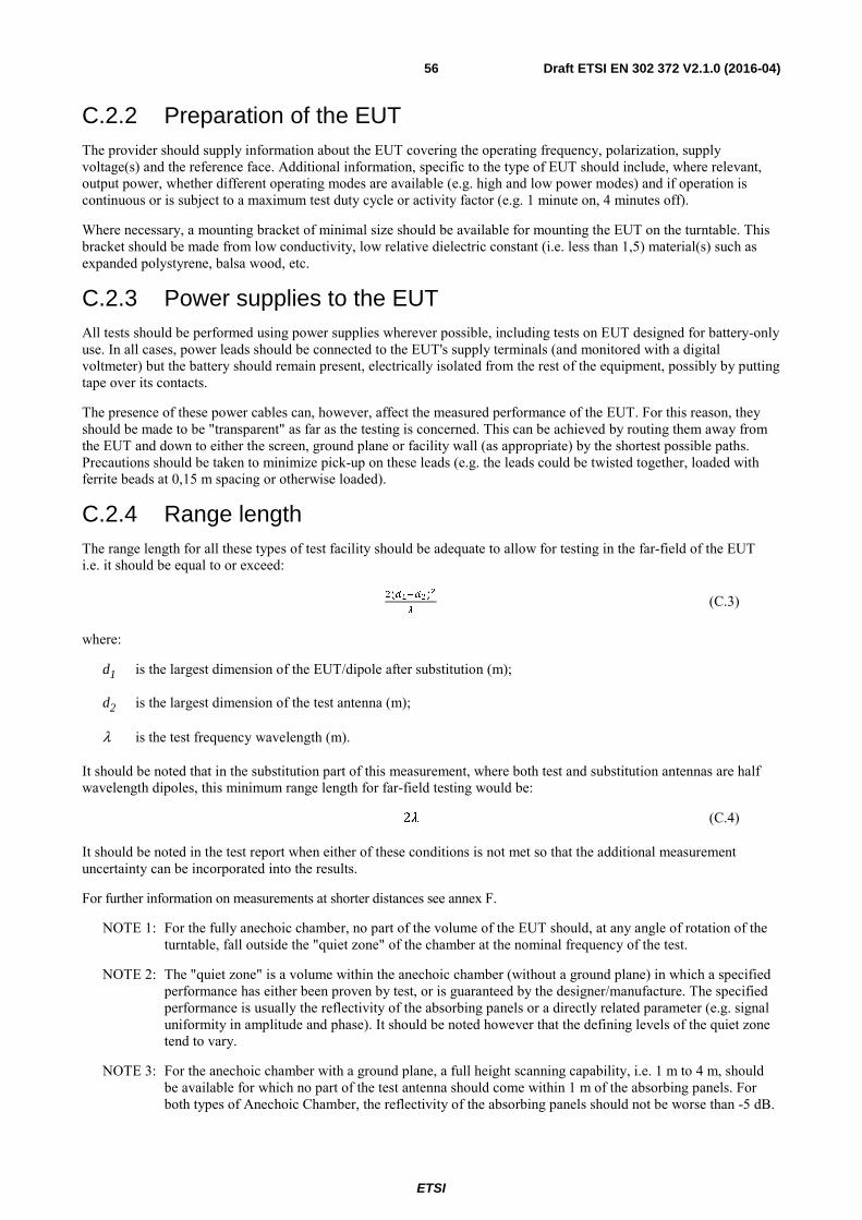
ETSI
Draft ETSI EN 302 372 V2.1.0 (2016-04) 56
C.2.2 Preparation of the EUT The provider should supply information about the EUT covering the operating frequency, polarization, supply voltage(s) and the reference face. Additional information, specific to the type of EUT should include, where relevant, output power, whether different operating modes are available (e.g. high and low power modes) and if operation is continuous or is subject to a maximum test duty cycle or activity factor (e.g. 1 minute on, 4 minutes off).
Where necessary, a mounting bracket of minimal size should be available for mounting the EUT on the turntable. This bracket should be made from low conductivity, low relative dielectric constant (i.e. less than 1,5) material(s) such as expanded polystyrene, balsa wood, etc.
C.2.3 Power supplies to the EUT All tests should be performed using power supplies wherever possible, including tests on EUT designed for battery-only use. In all cases, power leads should be connected to the EUT's supply terminals (and monitored with a digital voltmeter) but the battery should remain present, electrically isolated from the rest of the equipment, possibly by putting tape over its contacts.
The presence of these power cables can, however, affect the measured performance of the EUT. For this reason, they should be made to be "transparent" as far as the testing is concerned. This can be achieved by routing them away from the EUT and down to either the screen, ground plane or facility wall (as appropriate) by the shortest possible paths. Precautions should be taken to minimize pick-up on these leads (e.g. the leads could be twisted together, loaded with ferrite beads at 0,15 m spacing or otherwise loaded).
C.2.4 Range length The range length for all these types of test facility should be adequate to allow for testing in the far-field of the EUT i.e. it should be equal to or exceed:
%(7)
/ (C.3)
where:
d1 is the largest dimension of the EUT/dipole after substitution (m);
d2 is the largest dimension of the test antenna (m);
λ is the test frequency wavelength (m).
It should be noted that in the substitution part of this measurement, where both test and substitution antennas are half wavelength dipoles, this minimum range length for far-field testing would be:
2 (C.4)
It should be noted in the test report when either of these conditions is not met so that the additional measurement uncertainty can be incorporated into the results.
For further information on measurements at shorter distances see annex F.
NOTE 1: For the fully anechoic chamber, no part of the volume of the EUT should, at any angle of rotation of the turntable, fall outside the "quiet zone" of the chamber at the nominal frequency of the test.
NOTE 2: The "quiet zone" is a volume within the anechoic chamber (without a ground plane) in which a specified performance has either been proven by test, or is guaranteed by the designer/manufacture. The specified performance is usually the reflectivity of the absorbing panels or a directly related parameter (e.g. signal uniformity in amplitude and phase). It should be noted however that the defining levels of the quiet zone tend to vary.
NOTE 3: For the anechoic chamber with a ground plane, a full height scanning capability, i.e. 1 m to 4 m, should be available for which no part of the test antenna should come within 1 m of the absorbing panels. For both types of Anechoic Chamber, the reflectivity of the absorbing panels should not be worse than -5 dB.
ETSI
Draft ETSI EN 302 372 V2.1.0 (2016-04) 57
NOTE 4: For both the anechoic chamber with a ground plane and the Open Area Test Site, no part of any antenna should come within 0,25 m of the ground plane at any time throughout the tests. Where any of these conditions cannot be met, measurements should not be carried out.
C.2.5 Site preparation The cables for both ends of the test site should be routed horizontally away from the testing area for a minimum of 2 m (unless, in the case either type of anechoic chamber, a back wall is reached) and then allowed to drop vertically and out through either the ground plane or screen (as appropriate) to the test equipment. Precautions should be taken to minimize pick up on these leads (e.g. dressing with ferrite beads, or other loading). The cables, their routing and dressing should be identical to the verification set-up.
NOTE: For ground reflection test sites (i.e. anechoic chambers with ground planes and Open Area Test Sites) which incorporate a cable drum with the antenna mast, the 2 m requirement may be impossible to comply with.
Calibration data for all items of test equipment should be available and valid. For test, substitution and measuring antennas, the data should include gain relative to an isotropic radiator (or antenna factor) for the frequency of test. Also, the VSWR of the substitution and measuring antennas should be known.
The calibration data on all cables and attenuators should include insertion loss and VSWR throughout the entire frequency range of the tests. All VSWR and insertion loss figures should be recorded in the log book results sheet for the specific test.
Where correction factors/tables are required, these should be immediately available.
For all items of test equipment, the maximum errors they exhibit should be known along with the distribution of the error e.g.:
• cable loss: ±0,5 dB with a rectangular distribution;
• measuring receiver: 1,0 dB (standard deviation) signal level accuracy with a Gaussian error distribution.
At the start of measurements, system checks should be made on the items of test equipment used on the test site.
C.3 Coupling of signals The presence of leads in the radiated field may cause a disturbance of that field and lead to additional measurement uncertainty. These disturbances can be minimized by using suitable coupling methods, offering signal isolation and minimum field disturbance (e.g. optical and acoustic coupling).
C.4 Standard test methods
C.4.0 General Two methods of determining the radiated power of a device are described in clauses C.4.1 and C.4.2.
C.4.1 Calibrated setup The measurement receiver, test antenna and all associated equipment (e.g. cables, filters, amplifiers, etc.) shall have been recently calibrated against known standards at all the frequencies on which measurements of the equipment are to be made.
On a test site according to clause C.1, the equipment shall be placed at the specified height on a support, and in the position closest to normal use as declared by the provider.
The test antenna shall be oriented initially for vertical polarization and shall be chosen to correspond to the frequency of the transmitter.
The output of the test antenna shall be connected to the spectrum analyser via whatever (fully characterized) equipment is required to render the signal measurable (e.g. amplifiers).

ETSI
Draft ETSI EN 302 372 V2.1.0 (2016-04) 58
The transmitter shall be switched on, if possible without modulation, and the spectrum analyser shall be tuned to the frequency of the transmitter under test.
The test antenna shall be raised and lowered through the specified range of height until a maximum signal level is detected by the spectrum analyser.
The transmitter shall then be rotated through 360° in the horizontal plane, until the maximum signal level is detected by the spectrum analyser.
The test antenna shall be raised and lowered again through the specified range of height until a maximum signal level is detected by the spectrum analyser.
The maximum signal level detected by the spectrum analyser shall be noted and converted into the radiated power by application of the pre-determined calibration coefficients for the equipment configuration used.
C.4.2 Substitution method On a test site, selected from clause C.1, the equipment shall be placed at the specified height on a support, as specified in clause C.1, and in the position closest to normal use as declared by the provider.
The test antenna shall be oriented initially for vertical polarization and shall be chosen to correspond to the frequency of the transmitter.
The output of the test antenna shall be connected to the spectrum analyser.
The transmitter shall be switched on, if possible without modulation, and the measuring receiver shall be tuned to the frequency of the transmitter under test.
The test antenna shall be raised and lowered through the specified range of height until a maximum signal level is detected by the spectrum analyser.
The transmitter shall then be rotated through 360° in the horizontal plane, until the maximum signal level is detected by the spectrum analyser.
The test antenna shall be raised and lowered again through the specified range of height until a maximum signal level is detected by the spectrum analyser.
The maximum signal level detected by the spectrum analyser shall be noted.
The transmitter shall be replaced by a substitution antenna as defined in clause C.1.6.
The substitution antenna shall be orientated for vertical polarization and the length of the substitution antenna shall be adjusted to correspond to the frequency of the transmitter.
The substitution antenna shall be connected to a calibrated signal generator.
If necessary, the input attenuator setting of the spectrum analyser shall be adjusted in order to increase the sensitivity of the spectrum analyser.
The test antenna shall be raised and lowered through the specified range of height to ensure that the maximum signal is received. When a test site according clause C.1.1 is used, the height of the antenna shall not be varied.
The input signal to the substitution antenna shall be adjusted to the level that produces a level detected by the spectrum analyser, that is equal to the level noted while the transmitter radiated power was measured, corrected for the change of input attenuator setting of the spectrum analyser.
The input level to the substitution antenna shall be recorded as power level, corrected for any change of input attenuator setting of the spectrum analyser.
The measurement shall be repeated with the test antenna and the substitution antenna orientated for horizontal polarization.
The measure of the radiated power of the device is the larger of the two levels recorded at the input to the substitution antenna, corrected for gain of the substitution antenna if necessary.
ETSI
Draft ETSI EN 302 372 V2.1.0 (2016-04) 59
Annex D (normative): Conducted measurements In view of the low power levels of the equipment to be tested under the present document, conducted measurements may be applied to equipment provided with an antenna connector. Where the equipment to be tested does not provide a suitable termination, a coupler or attenuator that does provide the correct termination value shall be used.
The equivalent isotropically radiated power is then calculated from the measured value, the known antenna gain, relative to an isotropic antenna, and if applicable, any losses due to cables and connectors in the measurement system.
The Voltage Standing Wave Ratio (VSWR) at the 50 Ω connector shall not be greater than 1,5:1 over the frequency range of the measurement. For the purpose of the present document, conducted measurements are limited to the intended TLPR assigned frequency bands (see clause 4.3.1, table 2).

ETSI
Draft ETSI EN 302 372 V2.1.0 (2016-04) 60
Annex E (normative): Installation requirements of Tank Level Probing Radar (TLPR) equipment This annex provides the information for TLPR equipment manufacturers and installers to design the equipment and the installation in the tank in such a way, that the essential requirements of article 3.2 of the directive 2014/53/EU [i.6] are fulfilled.
The following installation requirements shall be fulfilled:
a) TLPR are required to be installed at a permanent fixed position at a closed (not open) metallic tank or reinforced concrete tank, or similar enclosure structure made of comparable attenuating material;
b) flanges and attachments of the TLPR equipment shall provide the necessary microwave sealing by design;
c) sight glasses shall be coated with a microwave proof coating when necessary (i.e. electrically conductive coating);
d) manholes or connection flanges at the tank shall be closed to ensure a low-level leakage of the signal into the air outside the tank;
e) whenever possible, mounting of the TLPR equipment shall be on top of the tank structure with the orientation of the antenna to point in a downward direction;
f) installation and maintenance of the TLPR equipment shall be performed by professionally trained individuals only.
The provider is required to inform the users and installers of TLPR equipment about the installation requirements and, if applicable, the additional special mounting instructions (e.g. by putting it in the product manual).
ETSI
Draft ETSI EN 302 372 V2.1.0 (2016-04) 61
Annex F (normative): Requirements on test tank The following requirements shall apply for a test tank:
• The test tank material shall be metal to demonstrate worst case for resonances and any unwanted tank radiation leakage.
• Test tank shall provide at least one mechanical connection for installing the TLPR. The method of mounting including the recommended product sealing used during the measurement shall be described in the Test report.
• The test tank shall be of cubic or cylinder shape with height/diameter ratio of 2 to 3 and volume shall not exceed 500 litres to demonstrate worst case power density inside the tank.
It shall be noted:
The dimension of a real-life tank is several orders of magnitude larger than the wavelength and thereby minimizes any resonance effect in the tank. The TLPR providers have not experienced high narrow band resonance effects for test tanks.
The test tank specified is used as a worst-case scenario for measuring the total emission outside the tank including the flange coupling and/or any potential tank resonance.
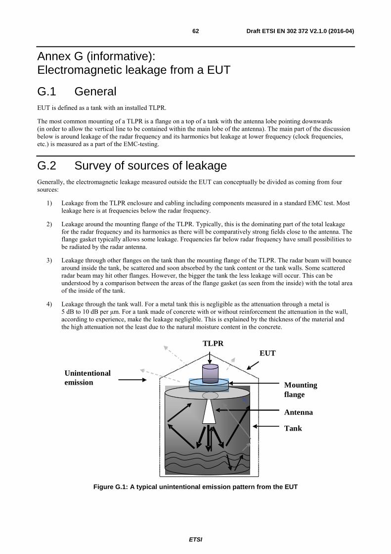
ETSI
Draft ETSI EN 302 372 V2.1.0 (2016-04) 62
Annex G (informative): Electromagnetic leakage from a EUT
G.1 General EUT is defined as a tank with an installed TLPR.
The most common mounting of a TLPR is a flange on a top of a tank with the antenna lobe pointing downwards (in order to allow the vertical line to be contained within the main lobe of the antenna). The main part of the discussion below is around leakage of the radar frequency and its harmonics but leakage at lower frequency (clock frequencies, etc.) is measured as a part of the EMC-testing.
G.2 Survey of sources of leakage Generally, the electromagnetic leakage measured outside the EUT can conceptually be divided as coming from four sources:
1) Leakage from the TLPR enclosure and cabling including components measured in a standard EMC test. Most leakage here is at frequencies below the radar frequency.
2) Leakage around the mounting flange of the TLPR. Typically, this is the dominating part of the total leakage for the radar frequency and its harmonics as there will be comparatively strong fields close to the antenna. The flange gasket typically allows some leakage. Frequencies far below radar frequency have small possibilities to be radiated by the radar antenna.
3) Leakage through other flanges on the tank than the mounting flange of the TLPR. The radar beam will bounce around inside the tank, be scattered and soon absorbed by the tank content or the tank walls. Some scattered radar beam may hit other flanges. However, the bigger the tank the less leakage will occur. This can be understood by a comparison between the areas of the flange gasket (as seen from the inside) with the total area of the inside of the tank.
4) Leakage through the tank wall. For a metal tank this is negligible as the attenuation through a metal is 5 dB to 10 dB per μm. For a tank made of concrete with or without reinforcement the attenuation in the wall, according to experience, make the leakage negligible. This is explained by the thickness of the material and the high attenuation not the least due to the natural moisture content in the concrete.
Mounting flange
Antenna
Tank
Unintentional emission
TLPR EUT
Figure G.1: A typical unintentional emission pattern from the EUT

ETSI
Draft ETSI EN 302 372 V2.1.0 (2016-04) 63
Thus, the total leakage outside of the tank will have the character of a diffuse leakage with small directivity. During the test procedure the total leakage can be measured essentially following standard EMC-procedures (with extended frequency range) searching for the direction of maximum radiation where the e.i.r.p. is measured.
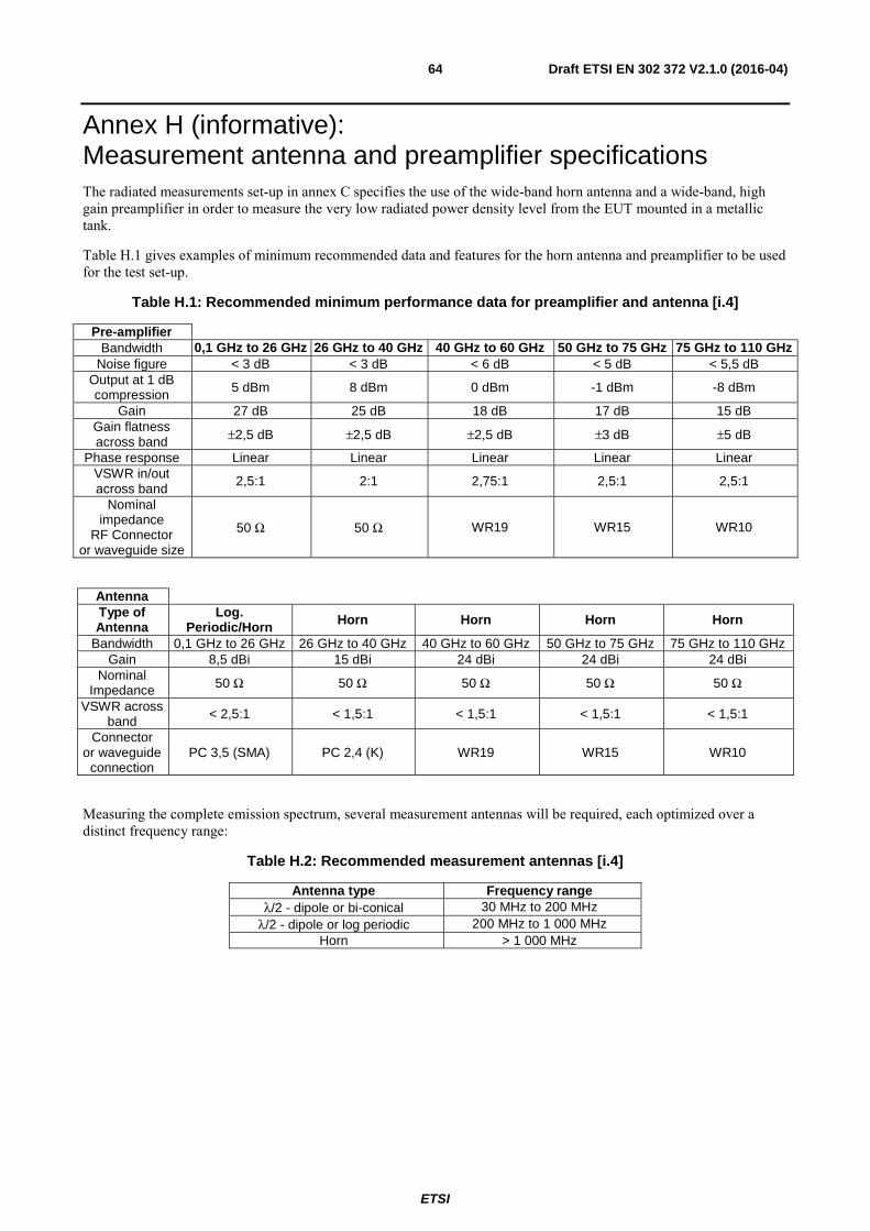
ETSI
Draft ETSI EN 302 372 V2.1.0 (2016-04) 64
Annex H (informative): Measurement antenna and preamplifier specifications The radiated measurements set-up in annex C specifies the use of the wide-band horn antenna and a wide-band, high gain preamplifier in order to measure the very low radiated power density level from the EUT mounted in a metallic tank.
Table H.1 gives examples of minimum recommended data and features for the horn antenna and preamplifier to be used for the test set-up.
Table H.1: Recommended minimum performance data for preamplifier and antenna [i.4]
Pre-amplifier Bandwidth 0,1 GHz to 26 GHz 26 GHz to 40 GHz 40 GHz to 60 GHz 50 GHz to 75 GHz 75 GHz to 110 GHz
Noise figure < 3 dB < 3 dB < 6 dB < 5 dB < 5,5 dB Output at 1 dB compression 5 dBm 8 dBm 0 dBm -1 dBm -8 dBm
Gain 27 dB 25 dB 18 dB 17 dB 15 dB Gain flatness across band ±2,5 dB ±2,5 dB ±2,5 dB ±3 dB ±5 dB
Phase response Linear Linear Linear Linear Linear VSWR in/out across band
2,5:1 2:1 2,75:1 2,5:1 2,5:1
Nominal impedance
RF Connector or waveguide size
50 Ω 50 Ω WR19 WR15 WR10
Antenna Type of Antenna
Log. Periodic/Horn Horn Horn Horn Horn
Bandwidth 0,1 GHz to 26 GHz 26 GHz to 40 GHz 40 GHz to 60 GHz 50 GHz to 75 GHz 75 GHz to 110 GHz Gain 8,5 dBi 15 dBi 24 dBi 24 dBi 24 dBi
Nominal Impedance 50 Ω 50 Ω 50 Ω 50 Ω 50 Ω
VSWR across band < 2,5:1 < 1,5:1 < 1,5:1 < 1,5:1 < 1,5:1
Connector or waveguide
connection PC 3,5 (SMA) PC 2,4 (K) WR19 WR15 WR10
Measuring the complete emission spectrum, several measurement antennas will be required, each optimized over a distinct frequency range:
Table H.2: Recommended measurement antennas [i.4]
Antenna type Frequency range λ/2 - dipole or bi-conical 30 MHz to 200 MHz
λ/2 - dipole or log periodic 200 MHz to 1 000 MHz Horn > 1 000 MHz

ETSI
Draft ETSI EN 302 372 V2.1.0 (2016-04) 65
Annex I (informative): Practical test distances for accurate measurements
I.1 Introduction It may not be possible to measure at the power limits without low-noise amplification to reduce the overall noise figure of the overall measurement system at a separation of approximately 3 meters in an RF quiet environment. A move to lower separation distance or reduced measurement bandwidth may be required since the instrumentation noise floor should be below the limit within the instrument bandwidth
The far field condition may imply impossible distances for accurate measurement of power limits or conventional antenna-pattern. For this purpose, a lower distance limit is discussed. Smaller distances can be used without loss of accuracy as long as the measurements are restricted to maximum power or amplitude.
I.2 Conventional near-field measurements distance limit A measurement of radiated power is made in front of an antenna. If the measurements are made too close to an antenna this will result in erroneous power readings. To avoid this, a minimum distance for antenna pattern measurements in an anechoic chamber should be in accordance with table I.1.
Table I.1: Uncertainty contribution: range length (test methods) [i.10]
Range length (i.e. the horizontal distance between phase centres)
Standard uncertainty of the contribution
(d1 + d2)2/4λ ≤ range length < (d1 + d2)2/2λ 1,26 dB
(d1 + d2)2/2λ ≤ range length < (d1 + d2)2/λ 0,30 dB
(d1 + d2)2/λ ≤ range length < 2(d1 + d2)2/λ 0,10 dB
range length ≥ 2(d1 + d2)2/λ 0,00 dB
NOTE: d1 and d2 are the maximum dimensions of the EUT and the test antenna, used in one stage and are the maximum dimensions of the two antennas in the other stage.
Two or even four times distance reduction may be applied. A further reduction will cause severe decrease of the accuracy. Further information can be found in ETSI TR 102 215 [i.10].
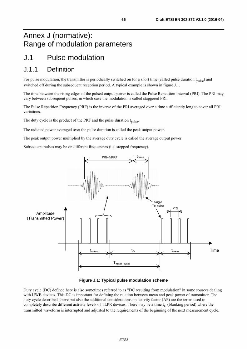
ETSI
Draft ETSI EN 302 372 V2.1.0 (2016-04) 66
Annex J (normative): Range of modulation parameters
J.1 Pulse modulation
J.1.1 Definition For pulse modulation, the transmitter is periodically switched on for a short time (called pulse duration tpulse) and switched off during the subsequent reception period. A typical example is shown in figure J.1.
The time between the rising edges of the pulsed output power is called the Pulse Repetition Interval (PRI). The PRI may vary between subsequent pulses, in which case the modulation is called staggered PRI.
The Pulse Repetition Frequency (PRF) is the inverse of the PRI averaged over a time sufficiently long to cover all PRI variations.
The duty cycle is the product of the PRF and the pulse duration tpulse.
The radiated power averaged over the pulse duration is called the peak output power.
The peak output power multiplied by the average duty cycle is called the average output power.
Subsequent pulses may be on different frequencies (i.e. stepped frequency).
Figure J.1: Typical pulse modulation scheme
Duty cycle (DC) defined here is also sometimes referred to as "DC resulting from modulation" in some sources dealing with UWB devices. This DC is important for defining the relation between mean and peak power of transmitter. The duty cycle described above but also the additional considerations on activity factor (AF) are the terms used to completely describe different activity levels of TLPR devices. There may be a time tG (blanking period) where the transmitted waveform is interrupted and adjusted to the requirements of the beginning of the next measurement cycle.
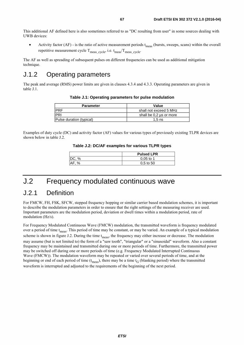
ETSI
Draft ETSI EN 302 372 V2.1.0 (2016-04) 67
This additional AF defined here is also sometimes referred to as "DC resulting from user" in some sources dealing with UWB devices:
• Activity factor (AF) - is the ratio of active measurement periods tmeas (bursts, sweeps, scans) within the overall repetitive measurement cycle Tmeas_cycle, i.e. tmeas/Tmeas_cycle.
The AF as well as spreading of subsequent pulses on different frequencies can be used as additional mitigation technique.
J.1.2 Operating parameters The peak and average (RMS) power limits are given in clauses 4.3.4 and 4.3.3. Operating parameters are given in table J.1.
Table J.1: Operating parameters for pulse modulation
Parameter Value PRF shall not exceed 5 MHz PRI shall be 0,2 µs or more Pulse duration (typical) 1,5 ns
Examples of duty cycle (DC) and activity factor (AF) values for various types of previously existing TLPR devices are shown below in table J.2.
Table J.2: DC/AF examples for various TLPR types
Pulsed LPR DC, % 0,05 to 1 AF, % 0,5 to 50
J.2 Frequency modulated continuous wave
J.2.1 Definition For FMCW, FH, FSK, SFCW, stepped frequency hopping or similar carrier based modulation schemes, it is important to describe the modulation parameters in order to ensure that the right settings of the measuring receiver are used. Important parameters are the modulation period, deviation or dwell times within a modulation period, rate of modulation (Hz/s).
For Frequency Modulated Continuous Wave (FMCW) modulation, the transmitted waveform is frequency modulated over a period of time tmeas. This period of time may be constant, or may be varied. An example of a typical modulation scheme is shown in figure J.2. During the time tmeas, the frequency may either increase or decrease. The modulation may assume (but is not limited to) the form of a "saw tooth", "triangular" or a "sinusoidal" waveform. Also a constant frequency may be maintained and transmitted during one or more periods of time. Furthermore, the transmitted power may be switched off during one or more periods of time (e.g. Frequency Modulated Interrupted Continuous Wave (FMCW)). The modulation waveform may be repeated or varied over several periods of time, and at the beginning or end of each period of time (tmeas), there may be a time tG (blanking period) where the transmitted waveform is interrupted and adjusted to the requirements of the beginning of the next period.
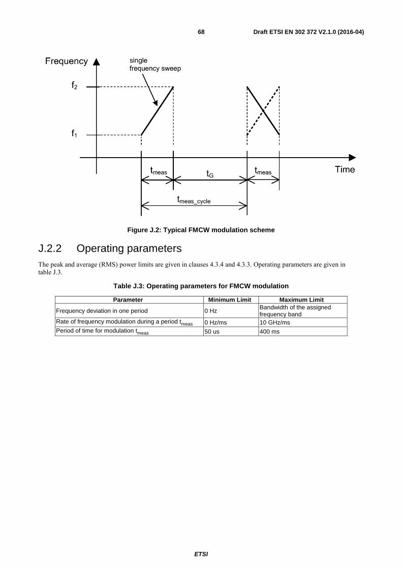
ETSI
Draft ETSI EN 302 372 V2.1.0 (2016-04) 68
Figure J.2: Typical FMCW modulation scheme
J.2.2 Operating parameters The peak and average (RMS) power limits are given in clauses 4.3.4 and 4.3.3. Operating parameters are given in table J.3.
Table J.3: Operating parameters for FMCW modulation
Parameter Minimum Limit Maximum Limit
Frequency deviation in one period 0 Hz Bandwidth of the assigned frequency band
Rate of frequency modulation during a period tmeas 0 Hz/ms 10 GHz/ms Period of time for modulation tmeas 50 us 400 ms

ETSI
Draft ETSI EN 302 372 V2.1.0 (2016-04) 69
Annex K (informative): Atmospheric absorptions and material dependent attenuations
K.1 Atmospheric absorptions In the frequency range between 40 GHz and 246 GHz the specific absorptions and material attenuations is an important factor for the compatibility of the different services potentially sharing the same operational band. In this annex an overview over the relevant parameters will be given for different materials and the atmospheric absorption.
With higher frequencies the effect of the atmospheric absorption gets more and more important in the investigation of the coexistence behaviour of short range wireless systems. In figure K.1 the specific absorption in the band between 1 GHz and 350 GHz is depicted. The diagram shows the absorption behaviour of dry air, of H2O and the combination of both. It can be seen that under normal conditions the absorption due to H2O is the most significant effect. Only in two spectral regions around 60 GHz and 120 GHz the dry air already shows very significant absorption behaviour. That means these absorptions are independent of the amount of H2O in the air. Especially the absorption peak around 60 GHz will be used to increase the isolation behaviour between different wireless systems. The absorption peak around 60 GHz originates from several oxygen absorption lines. A more detailed description of the behaviour around 60 GHz is depicted in figure K.2 for different altitudes between 0 km (sea level) and 20 km. Especially the 20 km diagram shows nicely the different absorption lines. The absorption peak around 60 GHz reaches 16 dB/km.

ETSI
Draft ETSI EN 302 372 V2.1.0 (2016-04) 70
Figure K.1: Specific attenuation due to atmospheric gases in the band 1 GHz to 350 GHz in dB/km

ETSI
Draft ETSI EN 302 372 V2.1.0 (2016-04) 71
Figure K.2: Specific Atmospheric attenuation in the band 50 GHz to 70 GHz for different altitudes (0 km, 5 km, 10 km, 15 km and 20 km) [i.5]
K.2 Material dependent attenuations The material dependent attenuation does also increase with the operational frequency. Typical attenuations for different materials are depicted in figure K.3 for the frequency range between 3 GHz and 200 GHz. These effects are important when coexistence scenarios are investigated between indoor and outdoor systems.
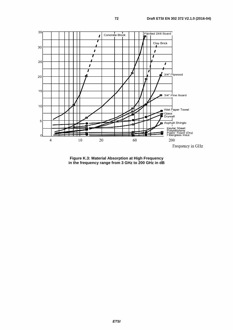
ETSI
Draft ETSI EN 302 372 V2.1.0 (2016-04) 72
Figure K.3: Material Absorption at High Frequency in the frequency range from 3 GHz to 200 GHz in dB
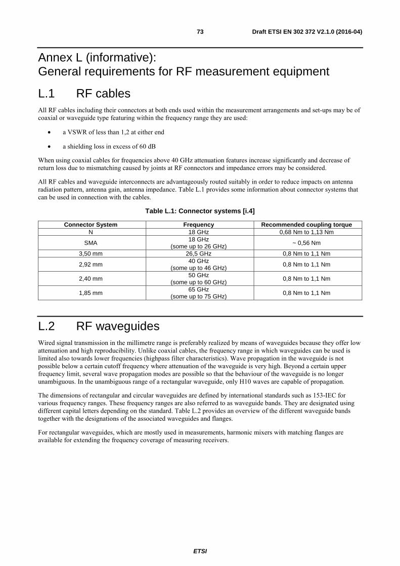
ETSI
Draft ETSI EN 302 372 V2.1.0 (2016-04) 73
Annex L (informative): General requirements for RF measurement equipment
L.1 RF cables All RF cables including their connectors at both ends used within the measurement arrangements and set-ups may be of coaxial or waveguide type featuring within the frequency range they are used:
• a VSWR of less than 1,2 at either end
• a shielding loss in excess of 60 dB
When using coaxial cables for frequencies above 40 GHz attenuation features increase significantly and decrease of return loss due to mismatching caused by joints at RF connectors and impedance errors may be considered.
All RF cables and waveguide interconnects are advantageously routed suitably in order to reduce impacts on antenna radiation pattern, antenna gain, antenna impedance. Table L.1 provides some information about connector systems that can be used in connection with the cables.
Table L.1: Connector systems [i.4]
Connector System Frequency Recommended coupling torque N 18 GHz 0,68 Nm to 1,13 Nm
SMA 18 GHz (some up to 26 GHz) ~ 0,56 Nm
3,50 mm 26,5 GHz 0,8 Nm to 1,1 Nm
2,92 mm 40 GHz (some up to 46 GHz) 0,8 Nm to 1,1 Nm
2,40 mm 50 GHz (some up to 60 GHz)
0,8 Nm to 1,1 Nm
1,85 mm 65 GHz (some up to 75 GHz) 0,8 Nm to 1,1 Nm
L.2 RF waveguides Wired signal transmission in the millimetre range is preferably realized by means of waveguides because they offer low attenuation and high reproducibility. Unlike coaxial cables, the frequency range in which waveguides can be used is limited also towards lower frequencies (highpass filter characteristics). Wave propagation in the waveguide is not possible below a certain cutoff frequency where attenuation of the waveguide is very high. Beyond a certain upper frequency limit, several wave propagation modes are possible so that the behaviour of the waveguide is no longer unambiguous. In the unambiguous range of a rectangular waveguide, only H10 waves are capable of propagation.
The dimensions of rectangular and circular waveguides are defined by international standards such as 153-IEC for various frequency ranges. These frequency ranges are also referred to as waveguide bands. They are designated using different capital letters depending on the standard. Table L.2 provides an overview of the different waveguide bands together with the designations of the associated waveguides and flanges.
For rectangular waveguides, which are mostly used in measurements, harmonic mixers with matching flanges are available for extending the frequency coverage of measuring receivers.

ETSI
Draft ETSI EN 302 372 V2.1.0 (2016-04) 74
Table L.2: Waveguide bands and associated waveguides [i.4]
Band Frequency Designations Internal
dimensions of waveguide
Designations of frequently used flanges
in GHz MIL-W-85 EIA 153-
IEC RCSC
(British) in mm in inches
MIL-F-3922
UG-XXX/U equivalent (reference)
Remarks
Ka 26,5 to 40,0 3-006 WR-28 R320 WG-22 7,11 x 3,56
0,280 x 0,140
54-006 68-002
67B-005
UG-559/U -
UG-381/U
Rectangular Rectangular
Round
Q 33,0 to 55,0 3-010 WR-22 R400 WG-23 5,69 x 2,84
0,224 x 0,112 67B-006 UG-383/U Round
U 40,0 to 60,0 3-014 WR-19 R500 WG-24 4,78 x 2,388
0,188 x 0,094 67B-007 UG-383/U-M Round
V 50,0 to 75,0 3-017 WR-15 R620 WG-25 3,759 x 1,879
0,148 x 0,074 67B-008 UG-385/U Round
E 60,0 to 90,0 3-020 WR-12 R740 WG-26 3,099 x 1,549
0,122 x 0,061 67B-009 UG-387/U Round
W 75,0 to 110,0 3-023 WR-10 R900 WG-27 2,540 x
1,270 0,100 x 0,050 67B-010 UG-383/U-M Round
As waveguides are rigid, it is impractical to set up connections between antenna and measuring receiver with waveguides. Either a waveguide transition to coaxial cable is used or - at higher frequencies - the harmonic mixer is used for frequency extension of the measuring receiver and is directly mounted at the antenna.
Due to the fact that external harmonic mixers can only be fed with low RF power it may be necessary to attenuate input powers in defined manner using wave guide attenuators.
L.3 External harmonic mixers
L.3.1 Introduction Measuring receivers (test receivers or spectrum analysers) with coaxial input are commercially available up to 67 GHz. The frequency range is extended from 26,5 GHz / 67 GHz up to 100 GHz and beyond by means of external harmonic mixers. Harmonic mixers are used because the fundamental mixing commonly employed in the lower frequency range is too complex and expensive or requires components such as preselectors which are not available. Harmonic mixers are waveguide based and have a frequency range matching the waveguide bands. They should not be used outside these bands for calibrated measurements.
In harmonic mixers, a harmonic of the local oscillator (LO) is used for signal conversion to a lower intermediate frequency (IF). The advantage of this method is that the frequency range of the local oscillator may be much lower than with fundamental mixing, where the LO frequency should be of the same order (with low IF) or much higher (with high IF) than the input signal (RF).The harmonics are generated in the mixer because of its nonlinearity and are used for conversion. The signal converted to the IF is coupled out of the line which is also used for feeding the LO signal.
To obtain low conversion loss of the external mixer, the order of the harmonic used for converting the input signal should be as low as possible. For this, the frequency range of the local oscillator should be as high as possible. LO frequency ranges are for example 3 GHz to 6 GHz or 7 GHz to 15 GHz. IF frequencies are in the range from 320 MHz to about 700 MHz. If the measured air interface is wider than the IF bandwidth, then it is advisable to split the measurement in several frequency ranges, i.e. a one-step total RF output power measurement should not be performed.
Because of the great frequency spacing between the LO and the IF signal, the two signals can be separated by means of a simple diplexer. The diplexer may be realized as part of the mixer or the spectrum analyser, or as a separate component. Mixers with an integrated diplexer are also referred to as three-port mixers, mixers without diplexers as two-port mixers. Figure L.1 shows an example where a diplexer is used to convey both, the IF and LO frequencies.

ETSI
Draft ETSI EN 302 372 V2.1.0 (2016-04) 75
Figure L.1: Set-up of measurement receiver, diplexer and mixer
Coaxial cable connections to an external mixer (diplexer) might be calibrated as well and in conjunction when calibrating the mixer and the measuring receiver. Those cables may not be replaced in concrete measurements.
Take car to have the mixer inputs sufficiently insulated towards the antenna port with regard to the injected signal (mixed signal) so that the mixed signal, multiplied by the LO, is sufficiently absorbed.
L.3.2 Signal identification A setup with Harmonic mixers without pre-selection displays always a pair of signals with a spacing of 2 x fIF, as there is no image suppression. For a modulated signal with a bandwidth of > 2 x fIF both, wanted and image response overlap and cannot be separated any more.
Depending on the width of the analysed frequency bands additional responses created from other harmonics may be displayed. In these cases it has to be determined by signal identification techniques, which of the displayed responses are false responses. Signal identification techniques implemented in spectrum analysers are based on the fact that only responses corresponding to the selected number of harmonic show a frequency spacing of 2 x fIF.
This can be used for automated signal identification: Apart from the actual measurement sweep, in which the lower sideband is defined as "wanted", a reference sweep is performed. For the reference sweep, the frequency of the LO signal is tuned such that the user-selected harmonic of the LO signal (order m') is shifted downwards by 2 x fIF relative to the measurement sweep.
Parameters which influence the signal identification routines are:
• Number of harmonic: The higher the harmonic number the more false responses will be created. A high LO frequency range which results in a lower harmonic number for a given frequency range is desirable.
• IF Frequency: The higher the IF frequency of the spectrum analyser, the greater the spacing at which image frequency response is displayed on the frequency axis. For a single modulated or unmodulated input signal displayed on the frequency axis, an image-free range of 2 x fIF is obtained around this signal in which no signal identification is necessary.
L.3.3 Measurement hints To obtain accurate and reproducible results, the following points should be observed:
• A low-loss cable with a substantially flat frequency response should be used for feeding the LO signal to the mixer. The conversion loss of the mixer is normally specified for a defined LO level. It is therefore important to maintain this level at the LO port of the mixer in order to achieve the desired accuracy. This is especially essential if the antenna/ mixer combination is located away from the measuring receiver.

ETSI
Draft ETSI EN 302 372 V2.1.0 (2016-04) 76
• In level correction on the spectrum analyser, the insertion loss of the cable used for tapping the IF signal is to be taken into account.
• If an external diplexer is used for connecting a two-port mixer, the insertion loss of the IF path of the diplexer is to be taken into account in level correction on the spectrum analyser.
Additional information on radiated measurements up to 100 GHz is available in ETSI TS 103 052 [i.4].
L.4 Preamplifier Preamplifiers may have asymmetric inputs and outputs with an impedance of 50 Ω. Preamplifier may be sufficiently calibrated with regard to frequency response, amplification factor, linearity and compression. Should this not be obtainable, the amplification factor may be determined at a certain frequency with a certain input power by substitution with a certain signal which is similarly defined as the original signal.
When using a preamplifier it considers be regarded that the amplifier has sufficient impulse response and that it is not overloaded with a too high input signal, which can lead to erroneous measurement results.
L.5 Measuring receiver The term "measuring receiver" refers to a frequency-selective voltmeter or a spectrum analyser. The measurement bandwidth of the measuring receiver is preferably, where possible, according to CISPR 16-1-1 [2]. In order to obtain the required sensitivity, a narrower measurement bandwidth may be necessary. In such cases, write this in the test report form. The bandwidth of the measuring receiver and the deployed detectors may be as given in table L.3.
Table L.3: Measurement receiver parameters [i.2]
Frequency range: (f) Measuring receiver bandwidth Detector 30 MHz ≤ f ≤ 1 000 MHz 100 kHz or 120 kHz peak/RMS (see note 1) 1 000 MHZ < f ≤ 40 GHz 1 MHz peak/RMS
f > 40 GHz 1 MHz (see note 2) peak/RMS NOTE 1: With the values from the peak and the RMS detector the quasi peak value can be calculated for
particular measurement applications. NOTE 2: Consider the actual frequency accuracy to determine the minimum measurement bandwidth
possible.
In case a narrower measurement bandwidth was used, the following conversion formula (L.1) has to be applied:
= + 10 ! .
. " (L.1)
Where:
• A is the value at the narrower measurement bandwidth;
• B is the value referred to the reference bandwidth; or
• use the measured value, A, directly if the measured spectrum is a discrete spectral line. (A discrete spectrum line is defined as a narrow peak with a level of at least 6 dB above the average level inside the measurement bandwidth.)
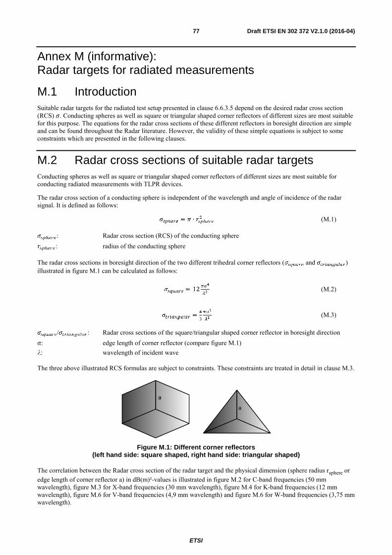
ETSI
Draft ETSI EN 302 372 V2.1.0 (2016-04) 77
Annex M (informative): Radar targets for radiated measurements
M.1 Introduction Suitable radar targets for the radiated test setup presented in clause 6.6.3.5 depend on the desired radar cross section (RCS) . Conducting spheres as well as square or triangular shaped corner reflectors of different sizes are most suitable for this purpose. The equations for the radar cross sections of these different reflectors in boresight direction are simple and can be found throughout the Radar literature. However, the validity of these simple equations is subject to some constraints which are presented in the following clauses.
M.2 Radar cross sections of suitable radar targets Conducting spheres as well as square or triangular shaped corner reflectors of different sizes are most suitable for conducting radiated measurements with TLPR devices.
The radar cross section of a conducting sphere is independent of the wavelength and angle of incidence of the radar signal. It is defined as follows:
= & ∙ % (M.1)
: Radar cross section (RCS) of the conducting sphere : radius of the conducting sphere
The radar cross sections in boresight direction of the two different trihedral corner reflectors ( and )) illustrated in figure M.1 can be calculated as follows:
= 123
/ (M.2)
) =
:
&
3
/ (M.3)
/): Radar cross sections of the square/triangular shaped corner reflector in boresight direction : edge length of corner reflector (compare figure M.1) : wavelength of incident wave
The three above illustrated RCS formulas are subject to constraints. These constraints are treated in detail in clause M.3.
Figure M.1: Different corner reflectors
(left hand side: square shaped, right hand side: triangular shaped)
The correlation between the Radar cross section of the radar target and the physical dimension (sphere radius rsphere or edge length of corner reflector a) in dB(m)²-values is illustrated in figure M.2 for C-band frequencies (50 mm wavelength), figure M.3 for X-band frequencies (30 mm wavelength), figure M.4 for K-band frequencies (12 mm wavelength), figure M.6 for V-band frequencies (4,9 mm wavelength) and figure M.6 for W-band frequencies (3,75 mm wavelength).

ETSI
Draft ETSI EN 302 372 V2.1.0 (2016-04) 78
Figure M.2: Radar cross sections as a function of the physical dimensions of different targets for C-band frequencies (wavelength 50 mm)
Figure M.3: Radar cross sections as a function of the physical dimensions of different targets for X-band frequencies (wavelength 30 mm)
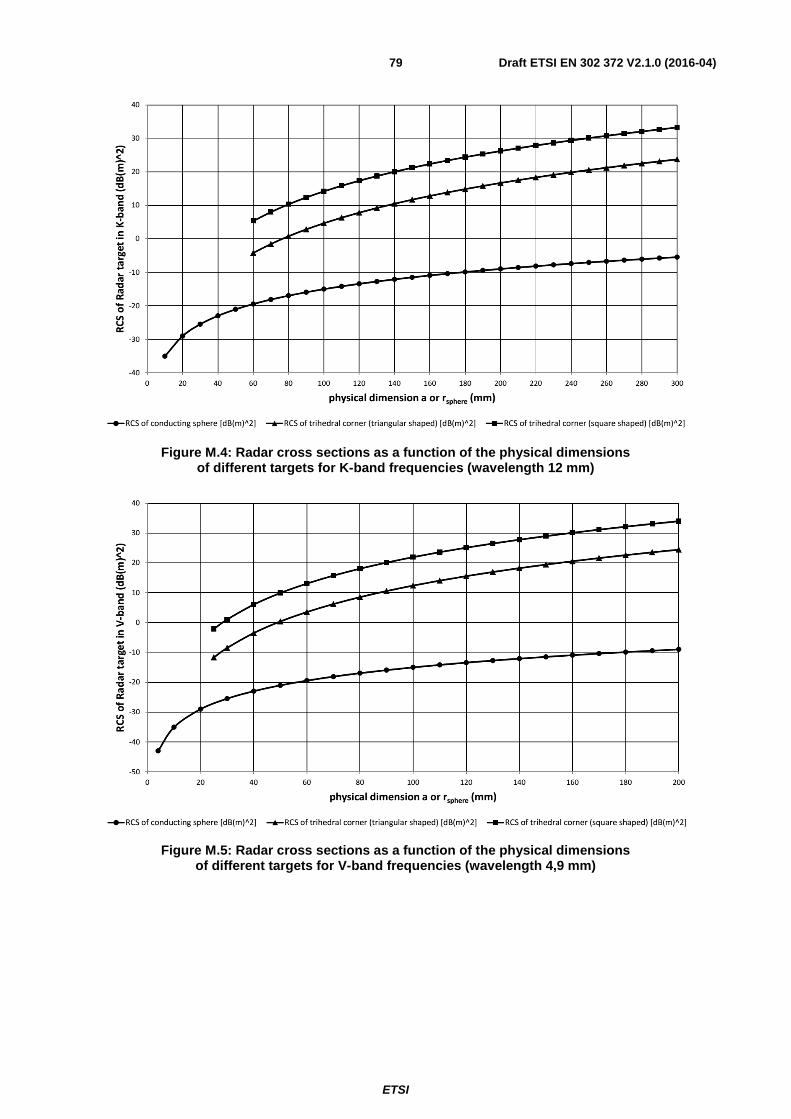
ETSI
Draft ETSI EN 302 372 V2.1.0 (2016-04) 79
Figure M.4: Radar cross sections as a function of the physical dimensions of different targets for K-band frequencies (wavelength 12 mm)
Figure M.5: Radar cross sections as a function of the physical dimensions of different targets for V-band frequencies (wavelength 4,9 mm)

ETSI
Draft ETSI EN 302 372 V2.1.0 (2016-04) 80
Figure M.6: Radar cross sections as a function of the physical dimensions of different targets for W-band frequencies (wavelength 3,75 mm)
M.3 Boundary conditions of the RCS equations The basis for the derivation of the RCS equations in clause M.2 is a geometric optics model. This model assumes that the wavelength is small with respect to the physical dimensions of the individual target reflector. Thus the RCS equations depicted in clause M.2 are subject to constraints concerning the relation between the used signal wavelength and the geometric extent of the targets.
The equation used for the Radar cross section of the conducting sphere is only valid if the following condition is fulfilled:
%3∙
/≥ 5 (M.4)
The equation used for the Radar cross section of the two corner reflectors ( and )) is only valid if the following condition is fulfilled:
/≥ 5 (M.5)
These two conditions lead to minimum sphere radii and minimum edge lengths with respect to the frequency of the incident wave. Table M.1 shows these minimum dimensions as a function of frequency for selected frequencies in the assigned TLPR frequency bands.
Table M.1: Minimum physical dimensions of the Radar targets as a function of frequency
Frequency of incident wave (GHz)
Minimum sphere radius rsphere (mm)
Minimum corner reflector edge length a (mm)
6 40 250 10 24 150 25 10 60 61 4 25 80 3 19
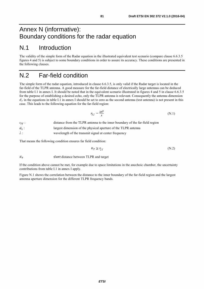
ETSI
Draft ETSI EN 302 372 V2.1.0 (2016-04) 81
Annex N (informative): Boundary conditions for the radar equation
N.1 Introduction The validity of the simple form of the Radar equation in the illustrated equivalent test scenario (compare clause 6.6.3.5 figures 4 and 5) is subject to some boundary conditions in order to assure its accuracy. These conditions are presented in the following clauses.
N.2 Far-field condition The simple form of the radar equation, introduced in clause 6.6.3.5, is only valid if the Radar target is located in the far-field of the TLPR antenna. A good measure for the far-field distance of electrically large antennas can be deduced from table I.1 in annex I. It should be noted that in the equivalent scenario illustrated in figures 4 and 5 in clause 6.6.3.5 for the purpose of establishing a desired echo, only the TLPR antenna is relevant. Consequently the antenna dimension % in the equations in table I.1 in annex I should be set to zero as the second antenna (test antenna) is not present in this case. This leads to the following equation for the far-field region:
=%
/ (N.1)
: distance from the TLPR antenna to the inner boundary of the far-field region # : largest dimension of the physical aperture of the TLPR antenna : wavelength of the transmit signal at center frequency
That means the following condition ensures far field condition:
≥ (N.2)
slant distance between TLPR and target
If the condition above cannot be met, for example due to space limitations in the anechoic chamber, the uncertainty contributions from table I.1 in annex I apply.
Figure N.1 shows the correlation between the distance to the inner boundary of the far-field region and the largest antenna aperture dimension for the different TLPR frequency bands.
ETSI
Draft ETSI EN 302 372 V2.1.0 (2016-04) 82
Figure N.1: Correlation between far-field distance and antenna aperture dimension
for the different TLPR frequency bands
N.3 Point target condition The simple form of the radar equation, introduced in clause 6.6.3.5, is only valid for point targets. That means the radar target should be either small enough or located far enough from the TLPR device in order to behave as a point target compared to the extent of the resolution cell in cross-range at the location of reflection.
Figure N.2 shows a simplified normalized power pattern of a potential TLPR antenna in one plane. The extent of the resolution cell in cross-range (angular resolution) is the same as the extent of the main lobe of the antenna pattern at the location of reflection in the slant distance RT. Thus from the antenna pattern in figure N.2 the angular resolution can be approximately derived as follows:
= 2sin!;%" (N.3)
: extent of the main lobe in slant distance RT
& : half power beamwidth (HPBW) or opening angle of the antenna pattern : slant distance between TLPR and target
The sphere can be considered as a point target if the following condition is fulfilled:
% ≥ 5 (N.4)

ETSI
Draft ETSI EN 302 372 V2.1.0 (2016-04) 83
Figure N.2: Simplified Normalized power pattern of a high directive antenna
The two corner reflectors can be considered as point targets if the following condition is fulfilled:
√%≥ 5 (N.5)
: edge length of corner reflector (compare figure M.1)

ETSI
Draft ETSI EN 302 372 V2.1.0 (2016-04) 84
Annex O (informative): Bibliography Commission Decision 2006/771/EC on harmonization of the radio spectrum for use by short range devices as amended by commission decision 2009/381/EC.
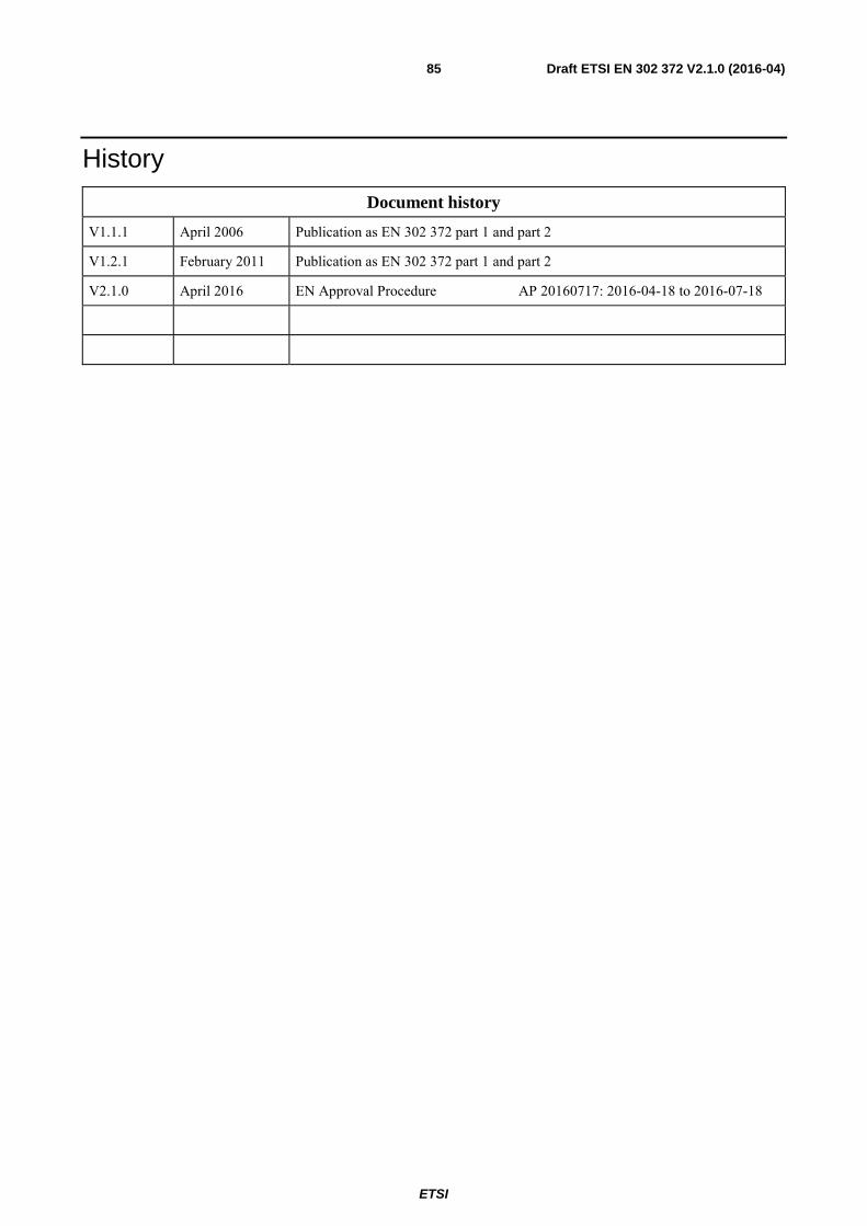
ETSI
Draft ETSI EN 302 372 V2.1.0 (2016-04) 85
History
Document history
V1.1.1 April 2006 Publication as EN 302 372 part 1 and part 2
V1.2.1 February 2011 Publication as EN 302 372 part 1 and part 2
V2.1.0 April 2016 EN Approval Procedure AP 20160717: 2016-04-18 to 2016-07-18