Draft Code of Practice for the Rehabilitation of Road ... of Practice for the Rehabilitation of Road...
147
Draft Code of Practice for the Rehabilitation of Road Pavements September 1998 (Reprinted July 2001) Prepared by the Division of Roads and Transport Technology, CSIR
-
Upload
duongtuyen -
Category
Documents
-
view
232 -
download
2
Transcript of Draft Code of Practice for the Rehabilitation of Road ... of Practice for the Rehabilitation of Road...

Draft
Code of Practicefor the
Rehabilitation of Road PavementsSeptember 1998
(Reprinted July 2001)
Prepared by the Division of Roads and Transport Technology, CSIR

i
PREFACE AND ACKNOWLEDGEMENT
This document is based closely on the South African guide to pavement rehabilitation, Draft TRH12:Pavement rehabilitation investigation and design, 1997. A number of detailed changes of varyingsignificance have been introduced in order to make the guide more appropriate to the SADC region, butthe basic format and content follows that of TRH12.
The cooperation of the South African Committee of State Road Authorities in granting permission tomake use of TRH12 as the basis for this document is gratefully acknowledged.

ii
TABLE OF CONTENTS
LIST OF TABLES . . . . . . . . . . . . . . . . . . . . . . . . . . . . . . . . . . . . . . . . . . . . . . . . . . . . . . . . . . . . . . . . iv
LIST OF FIGURES . . . . . . . . . . . . . . . . . . . . . . . . . . . . . . . . . . . . . . . . . . . . . . . . . . . . . . . . . . . . . . . . v
1. INTRODUCTION . . . . . . . . . . . . . . . . . . . . . . . . . . . . . . . . . . . . . . . . . . . . . . . . . . . . . . . . 1-11.1 Background . . . . . . . . . . . . . . . . . . . . . . . . . . . . . . . . . . . . . . . . . . . . . . . . . . . . . . . 1-11.2 Scope . . . . . . . . . . . . . . . . . . . . . . . . . . . . . . . . . . . . . . . . . . . . . . . . . . . . . . . . . . . . 1-11.3 Managing Pavement Rehabilitation Design . . . . . . . . . . . . . . . . . . . . . . . . . . . . . . 1-21.4 Recommended Approach . . . . . . . . . . . . . . . . . . . . . . . . . . . . . . . . . . . . . . . . . . . . 1-41.5 Management Considerations . . . . . . . . . . . . . . . . . . . . . . . . . . . . . . . . . . . . . . . . . . 1-6
2. PAVEMENT CONDITION ASSESSMENT . . . . . . . . . . . . . . . . . . . . . . . . . . . . . . . . . . . . 2-12.1 General . . . . . . . . . . . . . . . . . . . . . . . . . . . . . . . . . . . . . . . . . . . . . . . . . . . . . . . . . . . 2-12.2 Initial Assessment . . . . . . . . . . . . . . . . . . . . . . . . . . . . . . . . . . . . . . . . . . . . . . . . . . 2-12.3 Detailed Assessment . . . . . . . . . . . . . . . . . . . . . . . . . . . . . . . . . . . . . . . . . . . . . . . 2-25
3. REHABILITATION DESIGN APPROACH AND OPTIONS . . . . . . . . . . . . . . . . . . . . . . . 3-13.1 Objectives and Scope . . . . . . . . . . . . . . . . . . . . . . . . . . . . . . . . . . . . . . . . . . . . . . . 3-13.2 Rehabilitation Options . . . . . . . . . . . . . . . . . . . . . . . . . . . . . . . . . . . . . . . . . . . . . . . 3-13.3 Method Applicability . . . . . . . . . . . . . . . . . . . . . . . . . . . . . . . . . . . . . . . . . . . . . . . . . 3-23.4 Pavement Rehabilitation Design Methods . . . . . . . . . . . . . . . . . . . . . . . . . . . . . . . . 3-5
4. PRACTICAL AND FUNCTIONAL ASPECTS . . . . . . . . . . . . . . . . . . . . . . . . . . . . . . . . . . 4-14.1 Introduction . . . . . . . . . . . . . . . . . . . . . . . . . . . . . . . . . . . . . . . . . . . . . . . . . . . . . . . . 4-14.2 Applicability . . . . . . . . . . . . . . . . . . . . . . . . . . . . . . . . . . . . . . . . . . . . . . . . . . . . . . . 4-14.3 Constructability . . . . . . . . . . . . . . . . . . . . . . . . . . . . . . . . . . . . . . . . . . . . . . . . . . . . . 4-24.4 Performance Adequacy . . . . . . . . . . . . . . . . . . . . . . . . . . . . . . . . . . . . . . . . . . . . . . 4-34.5 Maintainability . . . . . . . . . . . . . . . . . . . . . . . . . . . . . . . . . . . . . . . . . . . . . . . . . . . . . . 4-4
5. ECONOMIC ANALYSIS . . . . . . . . . . . . . . . . . . . . . . . . . . . . . . . . . . . . . . . . . . . . . . . . . . . 5-15.1 Introduction . . . . . . . . . . . . . . . . . . . . . . . . . . . . . . . . . . . . . . . . . . . . . . . . . . . . . . . . 5-15.2 Agency costs . . . . . . . . . . . . . . . . . . . . . . . . . . . . . . . . . . . . . . . . . . . . . . . . . . . . . . 5-35.3 Road User Costs . . . . . . . . . . . . . . . . . . . . . . . . . . . . . . . . . . . . . . . . . . . . . . . . . . . 5-45.4 Principles of the Economic Analysis . . . . . . . . . . . . . . . . . . . . . . . . . . . . . . . . . . . . 5-65.5 Incorporating Uncertainty . . . . . . . . . . . . . . . . . . . . . . . . . . . . . . . . . . . . . . . . . . . . . 5-8
6. GLOSSARY OF TERMS . . . . . . . . . . . . . . . . . . . . . . . . . . . . . . . . . . . . . . . . . . . . . . . . . . 6-1
7. REFERENCES . . . . . . . . . . . . . . . . . . . . . . . . . . . . . . . . . . . . . . . . . . . . . . . . . . . . . . . . . . 7-1
APPENDIX A: CONDITION ASSESSMENT: PERFORMANCE CRITERIA FOR THE EVALUATION OFPAVEMENTS . . . . . . . . . . . . . . . . . . . . . . . . . . . . . . . . . . . . . . . . . . . . . . . . . . . . . . A-1
A.1 General . . . . . . . . . . . . . . . . . . . . . . . . . . . . . . . . . . . . . . . . . . . . . . . . . . . . . . . . . . . A-1A.2 Visually Recorded Distress . . . . . . . . . . . . . . . . . . . . . . . . . . . . . . . . . . . . . . . . . . . A-3A.3 Mechanical Pavement Surveillance Measurements . . . . . . . . . . . . . . . . . . . . . . . . A-5A.4 Pavement Evaluation Form . . . . . . . . . . . . . . . . . . . . . . . . . . . . . . . . . . . . . . . . . . . A-8

iii
APPENDIX B: PAVEMENT REHABILITATION DESIGNS USED IN SOUTHERN AFRICA:PRINCIPLES AND MAIN CHARACTERISTICS . . . . . . . . . . . . . . . . . . . . . . . . . . . B-1
B.1 Asphalt Institute Method . . . . . . . . . . . . . . . . . . . . . . . . . . . . . . . . . . . . . . . . . . . . . . B-1B.2 The DCP Method . . . . . . . . . . . . . . . . . . . . . . . . . . . . . . . . . . . . . . . . . . . . . . . . . . . B-4B.3 The TRL Surface Deflection Method . . . . . . . . . . . . . . . . . . . . . . . . . . . . . . . . . . . . B-7B.3 Shell Overlay Design Method . . . . . . . . . . . . . . . . . . . . . . . . . . . . . . . . . . . . . . . . B-10B.4 The South African Mechanistic Design Method . . . . . . . . . . . . . . . . . . . . . . . . . . . B-14
APPENDIX C: CONCEPTS IN DECISION THEORY . . . . . . . . . . . . . . . . . . . . . . . . . . . . . . . . . . . C-1
APPENDIX D: EXAMPLE: ECONOMIC ANALYSIS . . . . . . . . . . . . . . . . . . . . . . . . . . . . . . . . . . . D-1D.1 Background . . . . . . . . . . . . . . . . . . . . . . . . . . . . . . . . . . . . . . . . . . . . . . . . . . . . . . . D-1D.2 Sections Requiring Structural Strengthening . . . . . . . . . . . . . . . . . . . . . . . . . . . . . . D-1D.3 Sections Requiring Resealing . . . . . . . . . . . . . . . . . . . . . . . . . . . . . . . . . . . . . . . . . D-4
iv
LIST OF TABLES
Table 2.1: Modes and types of distress and their typical codes . . . . . . . . . . . . . . . . . . . . . . . . . . . 2-4Table 2.2: Classification of degrees of distress . . . . . . . . . . . . . . . . . . . . . . . . . . . . . . . . . . . . . . . . 2-5Table 2.3: Nominal road categories adopted for pavement rehabilitation design . . . . . . . . . . . . . . 2-8Table 2.4: Percentile levels recommended for data processing . . . . . . . . . . . . . . . . . . . . . . . . . . 2-10Table 2.5: Recommended relative damage exponents, n . . . . . . . . . . . . . . . . . . . . . . . . . . . . . . . 2-11Table 2.6: Estimation of average ESAs per heavy vehicle class . . . . . . . . . . . . . . . . . . . . . . . . . . 2-12Table 2.7: Converting thickness of existing pavement components to Effective Thickness9 . . . . 2-23Table 2.8: Summary of measurements most commonly used during a detailed assessment . . . 2-28Table 2.9: Nominal pavement state from deflection . . . . . . . . . . . . . . . . . . . . . . . . . . . . . . . . . . . 2-29Table 2.10: Typical surfacing life . . . . . . . . . . . . . . . . . . . . . . . . . . . . . . . . . . . . . . . . . . . . . . . . . . 2-39Table 3.1: Critical parameters and properties associated with various material types . . . . . . . . . . 3-4Table A.1: Typical unit lengths for the processing of project level data . . . . . . . . . . . . . . . . . . . . . . A-3Table A.2: Performance criteria for visually recorded distress . . . . . . . . . . . . . . . . . . . . . . . . . . . . A-4Table A.3: Percentile levels recommended for data processing . . . . . . . . . . . . . . . . . . . . . . . . . . . A-5Table A.4: Performance criteria recommended for the assessment . . . . . . . . . . . . . . . . . . . . . . . . A-5Table A.5: Criteria recommended for the assessment of structural condition . . . . . . . . . . . . . . . . . A-6Table A.6: Summary of the most commonly used deflection bowl parameters . . . . . . . . . . . . . . . A-8Table C.1: Resultant outcomes and actions for two time periods for any one initial action . . . . . . C-2

v
LIST OF FIGURES
Figure 1.1: Main elements of the various inputs influencing rehabilitation design . . . . . . . . . . . . . . 1-7Figure 2.1: Flow diagram of the pavement initial assessment . . . . . . . . . . . . . . . . . . . . . . . . . . . . . 2-2Figure 2.2: Relationship between standard deflection and life: granular road bases . . . . . . . . . . 2-16Figure 2.3: Relationship between standard deflection and life: granular road bases with
natural cementing action . . . . . . . . . . . . . . . . . . . . . . . . . . . . . . . . . . . . . . . . . . . . 2-17Figure 2.4: Relationship between standard deflection and life: bituminous road bases . . . . . . . . 2-17Figure 2.5: Relationship between standard deflection and life: cement-bound road bases . . . . . 2-18Figure 2.6: Design example for pavements with granular road bases whose aggregates
exhibit a natural cementing action (from Figure 2.3) . . . . . . . . . . . . . . . . . . . . . . . 2-19Figure 2.7: Relationship between pavement bearing capacity and DSN800 . . . . . . . . . . . . . . . . . . 2-21Figure 2.8: Thickness requirements for asphalt pavement structures using subgrade soil
CBR . . . . . . . . . . . . . . . . . . . . . . . . . . . . . . . . . . . . . . . . . . . . . . . . . . . . . . . . . . . . 2-24Figure 2.9: Flow diagram of pavement detailed assessment as part of the condition
assessment . . . . . . . . . . . . . . . . . . . . . . . . . . . . . . . . . . . . . . . . . . . . . . . . . . . . . . 2-26Figure 2.10: Nominal behaviour of pavement layers constructed with granular materials . . . . . . 2-30Figure 2.11: Nominal behaviour of lightly cemented pavement layers in a deep structure . . . . . . 2-32Figure 2.12: Nominal behaviour of pavement layers containing cement-treated materials . . . . . . 2-34Figure 2.13: Nominal behaviour of pavement layers with bitumen-treated materials . . . . . . . . . . 2-36Figure 2.14: Pavement situation identification . . . . . . . . . . . . . . . . . . . . . . . . . . . . . . . . . . . . . . . . 2-42Figure 3.1: Flow diagram of the rehabilitation design phase of a project-level investigation . . . . . . 3-2Figure 3.2: Main characteristics of the different empirically-derived approaches to
rehabilitation design . . . . . . . . . . . . . . . . . . . . . . . . . . . . . . . . . . . . . . . . . . . . . . . . . 3-6Figure 3.3: Empirical rehabilitation design methods based on condition assessment
approach . . . . . . . . . . . . . . . . . . . . . . . . . . . . . . . . . . . . . . . . . . . . . . . . . . . . . . . . . . 3-7Figure 3.4: Empirical rehabilitation design methods based on component analysis approach . . . . 3-8Figure 3.5: Empirical rehabilitation design methods based on the response analysis
approach . . . . . . . . . . . . . . . . . . . . . . . . . . . . . . . . . . . . . . . . . . . . . . . . . . . . . . . . . . 3-9Figure 3.6: Main characteristics of some approaches to pavement rehabilitation design
based on linear elastic stress-strain theory . . . . . . . . . . . . . . . . . . . . . . . . . . . . . . 3-11Figure 3.7: Applicability of rehabilitation design methods in relation to the main design
variables in a pavement situation, . . . . . . . . . . . . . . . . . . . . . . . . . . . . . . . . . . . . . 3-15Figure 3.8: Applicability of rehabilitation design methods in relation to the main performance
variables in a pavement situation, . . . . . . . . . . . . . . . . . . . . . . . . . . . . . . . . . . . . . 3-16Figure 3.9: Guidelines for the use of the recommended rehabilitation design methods, . . . . . . . . 3-17Figure 5.1: Economic analysis as part of project level pavement rehabilitation design . . . . . . . . . . 5-2Figure A.1: Example of completed form used for detailed visual inspection . . . . . . . . . . . . . . . . . . A-2Figure A.2: Performance criteria for visually recorded distress . . . . . . . . . . . . . . . . . . . . . . . . . . . . A-4Figure A.3: Criteria for measured maximum surface deflection (Benkelman beam) . . . . . . . . . . . . A-7Figure A.4: Criteria for measured radius of curvature (Dehlen curvature meter) . . . . . . . . . . . . . . . A-7Figure A.5: Example of a plot of the processed data for the evaluation of pavements . . . . . . . . . . A-9Figure B.1: Asphalt Institute method for structural design of pavement rehabilitation . . . . . . . . . . . B-2Figure B.2: Dynamic cone penetrometer method for pavement rehabilitation design . . . . . . . . . . . B-5Figure B.3: TRL method for the structural design of pavement rehabilitation . . . . . . . . . . . . . . . . . B-8Figure B.4: Simplified pavement structure . . . . . . . . . . . . . . . . . . . . . . . . . . . . . . . . . . . . . . . . . . . B-10Figure B.5: Shell method for the structural design of pavement rehabilitation . . . . . . . . . . . . . . . . B-12Figure B.6: Identification of the state and condition of a pavement . . . . . . . . . . . . . . . . . . . . . . . . B-15Figure B.7: SA mechanistic method for the structural design of pavement rehabilitation . . . . . . . B-17Figure C.1: Example of a given act with three possible outcomes . . . . . . . . . . . . . . . . . . . . . . . . . . C-1

vi
Figure C.2: Decision tree with outcomes and possible second acts for two time periods . . . . . . . . C-3Figure D.1: Decision tree for the �do nothing� alternative . . . . . . . . . . . . . . . . . . . . . . . . . . . . . . . . . D-6Figure D.2: Decision tree for Option 2 (conventional seal) . . . . . . . . . . . . . . . . . . . . . . . . . . . . . . . D-10Figure D.3: Decision tree for Option 3(a) (bitumen rubber) . . . . . . . . . . . . . . . . . . . . . . . . . . . . . . D-12
1-1
Code of practice for pavement rehabilitation Introduction
1. INTRODUCTION
1.1 Background
An increase in economic activity in southern Africa during the past few decades has led tomajor expansion and improvement of the road network throughout the region. A wide varietyof pavement types have been used for these roads, ranging from sand-sealed gravel roadsthrough waterbound macadam pavements and well-designed natural and stabilized gravelpavements, to sophisticated crushed stone and other composite pavements for the moreheavily trafficked routes.
After many years of good service, an increasing number of these roads are reaching acondition which warrants further attention and improvements in terms of riding quality andstrengthening of the pavement structure. To protect the integrity of these existing roads, a shiftin emphasis has taken place from the design and construction of new roads to the rehabilitationdesign and reconstruction of existing roads.
Experience has shown that if a deficient pavement is rehabilitated timeously, the costs involvedoften amount to a mere fraction of the cost of reconstruction.
This is achieved by using the remaining structural strength and behaviour of the existingpavement in the rehabilitation design for the road. Hence, rehabilitation design should includeprocedures that allow for the quantification and evaluation of the behaviour of the existingpavement structure. This information can then be incorporated into the rehabilitation design.
1.2 Scope
Pavement rehabilitation involves measures used to restore, improve, strengthen or salvageexisting deficient pavements so that these may continue, with routine and periodicmaintenance, to carry traffic with adequate speed, safety and comfort. Pavement rehabilitationis a part of road rehabilitation which also includes the rehabilitation of additional aspects suchas geometrics, safety, etc.
The main categories of pavement rehabilitation are:
� Complete pavement reconstruction. � Partial reconstruction involving the strengthening of existing pavement layers, with or
without stabilization, before resurfacing. � Asphaltic or granular overlays. � Provision of drainage, and/or improvements to existing drainage facilities.
Any combination of the above mentioned rehabilitation activities could be applicable to aspecific pavement. Furthermore, several available options exist within each of the mainrehabilitation categories from which a selection could be made. With all these alternativesavailable, the project level rehabilitation investigation procedure must identify the most suitableoption from both a structural and economical point of view.

1-2
Code of practice for pavement rehabilitation Introduction
The project level rehabilitation investigation procedure should aim to fully utilize all availableinformation on the existing pavements. This includes information on the design of thepavement, materials used, previous maintenance on the road, history of traffic loading andinformation available from the pavement management system of the Road Authority.
The purpose of this document is to provide guidance for project level rehabilitationinvestigations of flexible pavements. In this document only surfaced pavements areconsidered. Although design methods are recommended, no details thereof are included. Fullreferences to applicable rehabilitation design documents are included in Section 3(Rehabilitation design approach and options) of this document. Main characteristics of somepavement rehabilitation design methods in use in southern Africa are also included inAppendix B.
1.3 Managing Pavement Rehabilitation Design
1.3.1 GeneralA pavement is usually identified for rehabilitation by the various road authorities on the basisof information received from their regional offices as part of a pavement management system(PMS). Usually this information is related to the general visual condition and riding quality ofa pavement. Depending on various factors such as the type of pavement structure and theseverity of the problem, several rehabilitation options may be applicable.
Since not all roads within a network can be expected to be at the same level of deterioration,or even deteriorate at the same rate, the management of rehabilitation is usually divided intonetwork and project level activities. Only project level activities are covered in this document.Monitoring the condition of the pavement at network level is assumed to take place within aPMS, and would be aimed at identifying specific roads that may require structural rehabilitation.
1.3.2 Project Level Investigations: Design ConsiderationsA wrong decision on the required rehabilitation for a project could have substantial economicconsequences. Therefore, more detailed pavement condition tests are usually warranted ina project level study to improve confidence in the design and selection of an appropriaterehabilitation option. Many of the design variables which have to be assumed or estimated fora new pavement can be determined with reasonable accuracy on existing pavements. Theseinclude traffic conditions and the in situ strength parameters of the pavement components. Theaim of rehabilitation is to modify the behaviour of a pavement in order to carry the design trafficloading at an acceptable level of service. The more fully this behaviour is evaluated, the moreaccurate and therefore the more economical the rehabilitation should be.
All relevant factors which could contribute to distress must be considered during the evaluationof the pavement. These include:
� Traffic loading. � Drainage problems. � Non-traffic induced cracks. � The action of pumping under traffic. � Inadequate in-situ properties of pavement materials. � Expansive subgrades.

1-3
Code of practice for pavement rehabilitation Introduction
Although in some formal procedures these factors may be explicitly or tacitly recognized, theyare frequently not satisfactorily incorporated by the practising engineer. It is often difficult toidentify whether such factors have contributed to the cause and mechanism of distress, or todetermine the way in which they should be dealt with in the rehabilitation design.
To determine the best rehabilitation alternative it is essential to recognize that the futurebehaviour of a pavement cannot be predicted with certainty due to the variability of pavementmaterials and inadequate knowledge of their properties. Such uncertainty can be counteredto some extent through the use of extensive testing. However, it is necessary to be veryselective about the types and number of tests to keep the investigation within acceptablelogistic and economic limits. The designer achieves this by progressively determining thecontribution of additional testing until the degree of confidence necessary to determine theappropriate rehabilitation options has been obtained.
The ability of models based on pavement condition tests to predict the behaviour of pavementsis very limited for reasons such as:
� The varied nature of materials. � Differences between specified values and those actually achieved. � The simplistic nature of models in the face of many factors affecting the behaviour of
materials in pavements. � Uncertainty of traffic prediction.
The value of the additional information to be gained by further tests can be calculated explicitlyby statistical analysis when the problem is well-defined and has a simple structure. However,in pavement rehabilitation this is not always possible because of the complexity of thepavement, and the value of such information can often be assessed well enough for practicalpurposes by considering the cost of obtaining additional information in relation to the:
� Consequences of not making the optimal decision (in terms of cost and performance ofrehabilitation measure).
� Probability of not making the optimal decision without additional information. � Probability of not making the optimal decision in spite of having additional information.
Experience and engineering judgement can be used to assess these factors and decidewhether further tests are justified.
All tests should be aimed at improving the understanding of the behaviour of the pavement,rather than providing absolute information. Moreover, no type of test or analysis isprecluded, provided that it is appropriate and that it can be justified by the value of theinformation that will add to the understanding of the problem.
Based on the above principles and design considerations, the project level pavementrehabilitation approach outlined in this document will enable suitable rehabilitation options tobe determined through a systematic process of testing and analysis. This involves anassessment of the pavement condition, determination of existing structural capacity,identification of the cause and mechanism of distress, use of suitable rehabilitation designmethods and finally, the comparison of applicable options and strategies.

1-4
Code of practice for pavement rehabilitation Introduction
1.4 Recommended Approach
1.4.1 GeneralThis guide does not give rigid procedures that should be followed at all times: pavementrehabilitation projects differ considerably, which makes it impossible to give a recipe approachencompassing all possibilities. However, the principles contained in this document generallyrepresent accepted practice in southern Africa.
Normally, a particular length of road is identified for possible rehabilitation because of anexcessive need for routine maintenance, poor riding quality, increasing traffic-induced distress,or a combination of these factors. However, it is unlikely that such a length of road is uniformin respect of its rehabilitation needs. Some sections within a length of road may be distresseddue to localized factors, others may be exhibiting a problem limited to the surfacing, and soundsections may well exist between the distressed sections.
The objectives of the project level rehabilitation design procedure are, firstly, to divide thepavement into distinct lengths requiring different rehabilitation measures, and then to determinethe most suitable measure for each length.
Since the tests that will be needed to establish the appropriate rehabilitation measures for eachdifferent section of the road will not be known beforehand, the analysis should be carried outin iterative, increasingly detailed steps. These entail:
(i) Pavement condition assessment (detailed in Section 2)(initial assessment followed by more detailed analysis),
(ii) Rehabilitation design (detailed in Section 3) (iii) Economic analysis (detailed in Section 5)
Technically, the objectives of a project level rehabilitation investigation will be fully met byfollowing the three stages of the investigation as recommended. However, in practice,decisions and the process of investigations are continuously influenced by managerial andpractical aspects. These aspects are also discussed in Sections 1 and 4 respectively.
1.4.2 Pavement Condition AssessmentThe pavement condition assessment consists of an initial assessment, covering the whole ofthe project length, followed by more detailed investigations of sections exhibiting structuraldeficiencies. The aim is to concentrate more detailed and expensive testing on thosepavement sections requiring structural strengthening.
The initial assessment will normally entail a preliminary site visit and an examination ofavailable records, which will determine the need for tests such as deflection and profilemeasurements and a detailed visual inspection. Guidance for undertaking a detailed visualinspection is provided in Section 2 of this document.
The objectives of the initial assessments are:
(i) To identify sections where significant problems exist and the nature of these problems.This will establish sections:

1-5
Code of practice for pavement rehabilitation Introduction
� Where there is no significant problem. � Where the distress is obviously limited to the surfacing. � Where localized factors are the cause of the distress. � Which may be structurally inadequate.
(ii) To recommend: � Appropriate rehabilitation options for the surface distress,. � Remedial action for the localized distress. � Further tests for the sections where structural improvements may be required.
(iii) To provide: � A convenient record of initial measurements taken to describe the condition of the
pavement. � Input into the further analysis of sections in need of structural improvements.
Distress is considered a significant problem if it cannot be adequately dealt with through routinemaintenance as practised by the road authority concerned. In some cases the cause ofdistress is limited to the properties of the surfacing and is unrelated to the structural capacityof the pavement. Rehabilitation options, in such cases, can range from surface treatments tobituminous overlays, or even replacement of the surfacing, and could include recycling orapplication of surface rejuvenators. Usually the best option can only be determined afterfurther detailed testing of the distressed layer.
Deficient drainage is often the main cause of isolated distress. However, this type of distressmay also be due to design inadequacies, poor materials, or poor construction of a localizedsection. It is important to establish the exact cause of localized problems before attempting toselect the most economical remedial measure. This will prevent expensive rehabilitation of thewhole pavement length when only specific distressed areas need rehabilitation.
The initial assessment will have identified lengths of pavement in probable need of structuralimprovement. These lengths are examined further in order to ascertain the probable causeand mechanism of distress and the remaining structural capacity of the pavement. Thedistress may originate in any component of the pavement. For example, the deformation of thesurface may have been caused by the deformation of the subgrade or base, or cracking mayhave started in the base and be reflected through the surfacing. Moreover, in each case theremay be a number of reasons for the distress. The main objective of the detailed assessmentis to accurately define for each uniform section the pavement situation which is determined by:
� Pavement design variables, e.g. type and thickness of the pavement layers. � Traffic loading (past and future). � Environment (temperature and moisture). � Pavement performance. � Present condition (visual as well as pavement tests). � Cause and mechanism of distress.
The pavement situation of distress determines the type of rehabilitation which should be usedon a pavement and is also used to assess the applicability of rehabilitation design methods foruse on the pavement. Hence, enough testing should be done at this stage of the investigationto confidently determine and identify the pavement situation which describes in detail eachuniform pavement section.

1-6
Code of practice for pavement rehabilitation Introduction
1.4.3 Rehabilitation DesignThe pavement situation is used to rate rehabilitation design methods for the required structuralstrengthening of each uniform pavement section. More detailed testing may be required at thisstage of an investigation.
The fundamental reasons for each factor causing distress should be considered in determiningthe possible rehabilitation options. For subgrade deformation as discussed above, theappropriate options could well range from a levelling course overlay to a substantialstrengthening of the pavement structure, depending on the particular reasons for the subgradedeformation.
1.4.4 The Economic AnalysisA choice is made among the viable rehabilitation strategies and options by examining their costand the consequences of the use of the option in terms of the expected future behaviour of thepavement. After determining the expected costs of the project, as shown in Appendix D, acost-benefit analysis may be warranted to verify the viability of the project. The economicanalysis includes:
Selection of an OptionNormally, a number of rehabilitation options could be applicable for use on a particularpavement. Because of the variable nature of pavements, the effect of any treatment on thefuture behaviour of the pavement cannot be determined absolutely. The costs of eachrehabilitation option and the likely consequences of the treatment have to be weighed againstthe probability with which these consequences would occur. Normally the option that resultsin the lowest expected present worth of costs (PWOC) is selected for further analysis. Trafficdelay and other road user costs should also be taken into account in determining the PWOCof all options.
Selection of a StrategySeveral strategies may be followed using a specific rehabilitation option. The difference in costwill often not be decisive and the selection of a specific strategy could depend on localcircumstances and management considerations. Only after all factors have been consideredcan the most appropriate strategy be determined.
1.5 Management Considerations
1.5.1 Interaction of SystemsThe PMS, which is used to identify pavements requiring rehabilitation, is mainly a tool assistingmanagement in taking meaningful and rational decisions. The PMS provides input for, and isinfluenced by, functions such as planning, budgeting, resource allocation, etc.
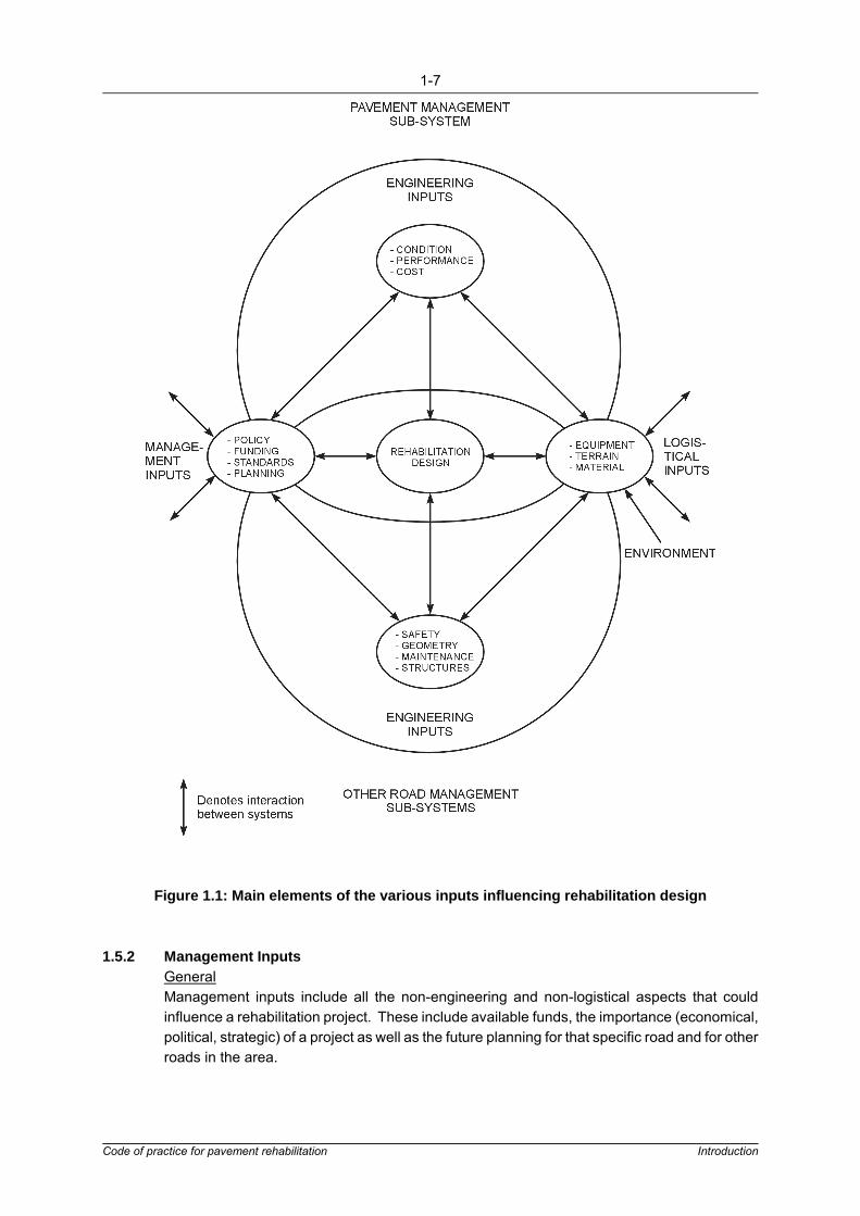
The various inputs affecting pavement rehabilitation design are illustrated in Figure 1.1. It isseen that pavement rehabilitation is influenced by pavement engineering inputs,pavement-related engineering inputs, management inputs and logistical inputs.
All these inputs should be noted at the earliest possible opportunity because of their possibleoverriding influence on an investigation. The main elements of each of these inputs arediscussed in detail below.
1-7
Code of practice for pavement rehabilitation Introduction
Figure 1.1: Main elements of the various inputs influencing rehabilitation design
1.5.2 Management InputsGeneralManagement inputs include all the non-engineering and non-logistical aspects that couldinfluence a rehabilitation project. These include available funds, the importance (economical,political, strategic) of a project as well as the future planning for that specific road and for otherroads in the area.

1-8
Code of practice for pavement rehabilitation Introduction
Equally important is the policy of the road authority with regard to standards, including safetyand liaison with other road authorities, taking into account their specific future planning in caseswhen a route could be influenced by their actions.
As shown in Figure 1.1, management inputs are also influenced by the specifics of any project.Hence, it is important to keep management informed and to discuss the consequences oftechnical as well as financial decisions. Close co-operation between management and thedesigner should also ensure that management is supplied with the information it needs to maketimeous decisions if and when the scope of a project needs to be changed.
FundingIn the past, road funding was provided according to the demands of the various governmentagencies. This system worked well during periods when funding kept pace with the needs asidentified by the various road authorities. However, this is no longer the case and roadauthorities are finding it increasingly difficult to meet their commitments and to convincefunding authorities of the need for funds to upgrade and maintain their networks.
Hence, financial planning should form an integral part of road network planning as well as ofroad maintenance and rehabilitation planning.
For example, limited funds may make it impractical to investigate in detail relatively expensivelong-term solutions. In such a case the management input of "limited funds" should guide thedesigner to concentrate his investigation on relatively less expensive short-term solutions.
Proper financial planning should identify needs, develop managerial strategies, make the bestuse of limited resources, reduce uncertainty and help educate the public and public officials.Up-to-date information on the condition of the road network, future transportation needs andconsequences of funding levels must form part of financial planning, thus enabling roadauthorities to negotiate funds in competition with other government agencies and departments.
The identification and selection of rehabilitation projects should therefore be based on soundeconomic principles. For this purpose, the anticipated costs and benefits of projects must bedetermined to enable the calculation of feasibility indicators such as the cost-benefit ratio, theEconomic Internal Rate of Return (EIRR), Present Worth of Costs (PWOC) and Nett PresentValue (NPV).
PolicyThe policy of a road authority is normally based on many years of practical experience. Thismay concern practical aspects such as the use of certain materials, equipment and/orprocedures. Certain policy aspects may evolve or change with time due to new developmentssuch as improved techniques, materials, equipment, better information, or because of forcedchanges related to government policy, such as lower levels of funding, or strategicdevelopment of certain areas or industries.
Hence, policy is an integral part of the planning of the transport system. Changes in inputcould, in a well organized structure, lead to changes in policy to accommodate and perhapscounter these influences. Policy aspects should be considered as inputs into a project-levelrehabilitation study and the designer should keep informed of the policies of specific roadauthorities.

1-9
Code of practice for pavement rehabilitation Introduction
However, because of the uniqueness of every rehabilitation investigation and the technicalexpertise required from the designers involved in rehabilitation projects, it is not advisable toformulate a rigid policy regarding technical prescriptions for pavement rehabilitation projects.Nevertheless, policy can be made regarding:
� The extent to which the various levels of an investigation should be carried out and thegeneral approach the investigator should follow.
� The standards applicable to specific roads (including design life) and the extent to whichroad-related aspects such as safety should be investigated.
� The appointment and method of payment of the designer (rehabilitation projects oftenrequire more expertise and input than new projects, and the policies regardingcompensation of the designer should take this into account).
StandardsRoad authorities may have different policies regarding standards for pavement rehabilitationprojects. These standards would normally relate to the pavement category, taking into accountpavement structure, traffic loading and the riding quality of the road. The standards should bea function of the class of pavement and relate to the importance of the road and the traffic (bothvolume and load) that the pavement carries.
The duty of the road authority is to set specific standards according to which roads should beevaluated, and to prescribe standards to which a road should be rehabilitated. Understandably,policy changes and changes in level of funding could influence standards. However, thelowering of standards to "balance the books" is not advisable due to the possibility of some"sub-standard" rehabilitated road sections in a network. Road authorities should aim tomaintain appropriate standards, taking cost implications into account.
Standards for the rehabilitation of pavements should not only refer to aspects of the structureof the pavement, but also to related technical matters such as safety, geometrics and capacity.
Road authorities should therefore prescribe appropriate standards for the assessment andimprovement of these aspects during rehabilitation projects.
PlanningThe above-mentioned aspects related to funding, policy and standards all form an integral partof the planning of a road authority. In addition, many other aspects should be taken intoaccount during the planning of rehabilitation projects. These also include non-technicalaspects not necessarily concerning the designer, but important to management. Theseinclude:
� Programmes of road authorities, neighbouring states and provinces: projects should notbe decided upon in isolation. The planning of road authorities "across the border",concerning one or several other roads in the same area which could influence theproject, should be taken into account.
� Strategic roads: the need for the improvement of a road could also depend onnon-structural and non-traffic associated considerations such as strategic planning. Inthis regard state departments should liaise with each other and road authorities shouldhave insight into the transportation requirements as influenced by government policysuch as strategic roads, accessibility to distant markets and decentralization.

1-10
Code of practice for pavement rehabilitation Introduction
1.5.3 Logistical InputsEquipmentThe investigation should take cognisance of the availability of special equipment needed forinvestigation and the construction of rehabilitation. Some rehabilitation options, such as thein-place hot-mix recycling of asphaltic layers, may require highly sophisticated and/orexpensive equipment which may not be readily available.
In cases where equipment is not available, the cost to the contractor, and thus to the project,of manufacturing, importing or buying such equipment should be taken into account in theevaluation of specific options.
Only a limited number of pieces of specialized equipment, such as the Deflectograph andFalling Weight Deflectometer (FWD), used for the measuring of pavement condition may beavailable in the country. Thus, rehabilitation investigations should be planned around theavailability of such equipment. Good communication between the respective road authoritiesand their designers should ensure that projects are planned taking into account the availabilityof equipment.
TerrainTerrain conditions and associated restrictions could limit the rehabilitation options which canbe considered for a specific project. The early identification of such terrain-associatedproblems could save considerable time in the design and consideration of possiblerehabilitation options. These problems include:
� Traffic accommodation problems: the characteristics of a project could be such thattraffic cannot be accommodated at a reasonable cost other than on the existing road.In these cases the designer should concentrate on options which will cause minimumdisruption to the traffic using the route. Aspects that could contribute to such a situationinclude:
- Congested areas in cities where traffic can only be accommodated withgreat difficulty.
- Mountainous areas where alternatives for the accommodation of traffic canbe very expensive.
� Bridge or obstacle clearance: the rehabilitation design must ensure that adequateclearance under any obstacle such as a bridge is maintained. Specifications of roadauthorities should be adhered to and possible problems should be identified early in theinvestigation to allow for these cases to be accommodated in the design.
� Roadside furniture: the presence of, and height of, roadside furniture such as curbscould influence a decision on the applicability of a rehabilitation option, especially in anurban situation. The placement of asphalt overlays on roads with curbs could lead to thepavement being considerably higher than the curb. In such cases the removal orrecycling of the asphalt layer could be considered. Similar problems could occur on ruralroads with concrete side drains adjacent to the surfaced area.
� Services: the presence of services crossing or alongside the surfaced road should benoted and allowed for in the design of pavement rehabilitation options.

1-11
Code of practice for pavement rehabilitation Introduction
MaterialsDuring the pavement condition assessment a survey of road-building materials available in thevicinity of the road should be made. The non-availability of good quality materials could haveserious economic implications for a specific project. The early identification of materialresources could save considerable effort during the design phase of an investigation.
1.5.4 Engineering Inputs From Other Sub-systemsTraditionally, rehabilitation design projects are mainly identified as a result of problemsassociated with the pavement structure. Although road authorities often require an evaluationof the geometric aspects of a road during a rehabilitation investigation, safety and associatedaspects are sometimes neglected. Input from a related sub-system such as geometrics couldmake it unnecessary to investigate the pavement structure over certain lengths of the roadwhich will be influenced by geometric changes.
Many roads considered for rehabilitation will not originally have been designed to modernstandards. The opportunity presented by a rehabilitation investigation should also be used tomake a full appraisal of the safety, capacity and geometric aspects of the road. However,experience has shown that many "required" improvements are not cost-effective and, ifaccommodated, may change the cost-benefit ratio of a project and render it uneconomic.
Improvements such as substantial re-alignment, geometric improvements, drainage andperhaps even the widening of the pavement may fall into this category. However, manyopportunities for low-cost and hence cost-effective safety improvements may exist for theseolder roads.
The responsibility rests with the authority and the designer to ensure that the road adheres toreasonable safety standards, although these may not necessarily be the same as thoseapplicable to new roads. Many aspects such as improved signboards, removal of obstaclesclose to the road, improvement of shoulders, etc, could be addressed at low additional costduring pavement rehabilitation. These improvements could be based on appropriate standardsfor pavement rehabilitation projects.
Alternative solutions for the improvement of the safety of roads may include methods andguidelines to improve aspects related to:
� Lane widths � Shoulder widths � Horizontal alignment and super-elevations � Vertical alignment and sight distance � Bridge widths � Sideslopes and clear zones � Pavement shoulder condition, including edge drops and drainage � Intersections � Pavement surface condition. � Climbing lanes.
Applicable standards for the consideration of improvements related to the above could dependon:
� Changes in accident rates, user time and vehicle operating costs that can be expectedwith the improvement of a specific geometric aspect.

1-12
Code of practice for pavement rehabilitation Introduction
� Increases in accident rates that can be expected if the riding surface is improved withoutaddressing safety aspects.
� Safety benefits of low-cost alternatives, such as traffic signals and markings, comparedto more expensive improvements.
In many cases the traffic volume expected on the road may warrant upgrading of the road interms of widening or surfacing of shoulders. Again, the cost implications of such improvementsshould be carefully considered and the assessment of improvements required in terms ofcapacity should be carried out in conjunction with related traffic engineering aspects such asgeometry and safety.

2-1
Code of practice for pavement rehabilitation Pavement condition assessment
2. PAVEMENT CONDITION ASSESSMENT
2.1 General
The condition assessment forms the basis of the investigation and design procedurerecommended in this document, and the primary aims of the condition assessment are to:
� Identify uniform pavement sections and to establish general structural and/or functionalneeds through an initial assessment of the road.
� Determine the cause and mechanism of distress and the pavement situation through amore detailed assessment.
The nature and level of detail of the condition assessment should take into account the:
� Class of road. � Resources available. � Quantity and nature of the data already available concerning the pavement.
Depending on the requirements of the client, a preliminary report may be requested at the endof the condition assessment. Such a report may require the identification of preliminaryrehabilitation needs and their economic implications. Section 3 (Rehabilitation design) andSection 5 (Economic analysis) of this document provide guidance on these aspects.
The initial and detailed assessments are often interwoven and therefore grouped together asthe condition assessment. However, for the purpose of clarity, the objectives and scope ofeach are discussed separately.
2.2 Initial Assessment
2.2.1 Objectives and ScopeThe objectives of the initial assessment are accomplished by:
� Recording and processing of data in a form that can be readily used in subsequentdetailed investigations.
� Dividing the pavement length under examination into sections requiring differentmeasures.
� Recommending appropriate measures for sections that obviously exhibit only surfacingdistress or isolated distress.
� Identifying appropriate tests required on specific sections of the pavement fordetermining, with confidence, the cause and mechanism of distress and the pavementsituation.
In achieving the above objectives the initial assessment is divided into:
� Gathering of information. � Data processing. � Pavement evaluation and initial structural capacity analysis of uniform sections.

2-2
Code of practice for pavement rehabilitation Pavement condition assessment
The recommended approach for the initial assessment is outlined in Figure 2.1. From thisfigure it is clear that the gathering of information and the processing and evaluation of data areintegrated to allow for the optimal use of available data before embarking on any further testingof the pavement.
Figure 2.1: Flow diagram of the pavement initial assessment
The division between network level and project level tasks is not, and should not, be clearlydefined. With Pavement Management Systems becoming more advanced, some of the tasksshown in Figure 2.1 could in time be incorporated into network level assessments.

2-3
Code of practice for pavement rehabilitation Pavement condition assessment
2.2.2 Gathering of InformationPreliminary InvestigationThis investigation entails the collection of all available information such as as-built data,pavement structure data and traffic loadings on the pavement, as well as any results from testspreviously done on the road (such as information about the history of the pavement condition).Existing PMSs are usually an excellent source for obtaining this information.
A preliminary site inspection is essential especially if the assessor is not familiar with thepavement under investigation.
Detailed Visual Inspectiona) General
Information from visual inspections contained in PMSs is generally not detailed enoughfor use in project level rehabilitation investigations. Hence a detailed visual inspectionis considered an essential part of a condition assessment.
Distress visible on the pavement surface is recorded in great detail in a way compatiblewith the eventual evaluation of the data. Of particular importance is the recording ofvisual clues to the cause and mechanism of distress. These include details such asconstruction aspects (e.g. cuttings, high embankments, etc), drainage facilities andobvious topographical and geological features.
b) Basic requirementsTo permit observation of the required detail, it is recommended that the visual survey becarried out by walking to ensure quality results in relation to the type of distress andlength of the project.
It is recommended that the inspection be carried out by two persons who both have acomprehensive knowledge of pavement distress and its causes. At the same time thatthis investigation is carried out, it is often practical and economical, using additionalinspectors, to record all pertinent detail in the road reserve from fence to fence such asthe location and condition of all drainage structures, road signs, lay-bys, guardrails,fencing, signs of erosion and flooding, intersections and other road furniture. It is normalduring a rehabilitation contract to allow for repairs and improvements within the roadreserve and this information is essential.
Different modes and types of distress are discussed in detail in TRH61 and TMH92.These documents, together with the applicable documentation issued by the variousroad authorities, should be studied before the visual inspection.
The visual inspection should be carefully planned. A form, an example of which isshown in Appendix A, must be prepared for recording all the relevant information.However, it is important that the detail and the number of variables considered are keptwithin manageable proportions.
Knowledge of the local geology and of the pavement structure will assist in theinterpretation of field observations.

2-4
Code of practice for pavement rehabilitation Pavement condition assessment
c) Recording of distress in pavementsVisible signs of distress as well as possible clues as to the cause of the distress mustbe recorded. For this purpose, the following information is relevant:
� Location of distress � Mode and type of distress � Degree and extent of distress � Position and spacing of distress � Pertinent construction details and deficiencies � Topographical, geological and vegetational clues to the cause of distress � Drainage structures/facilities.
i. Location of distressThe inspection must provide an accurate record of the location of each particularmode and type of distress that is evident. The location is given in relation to thelength of the road, usually based on km posts, but pre-marking may be necessaryto provide suitable reference.
ii. Mode and type of distressFour main modes of visible distress are used:
� Deformation or unevenness � Cracking (surfacing or structural problems) � Disintegration (surfacing or structural problems) � Smoothing of the surface texture (skid resistance).
These modes of distress are manifested in several typical ways and Table 2.1gives details, together with the codes generally used to identify the types on aninspection form (see Appendix A for typical forms).
Different types of distress within the same mode are generally brought about bydifferent causes. It is therefore important that individual types be recordedseparately where practicable. However, a differentiation into all the types listedabove will not always be relevant for an assessment, and therefore not essentialfor every visual survey.
Table 2.1: Modes and types of distress and their typical codes
Mode of Distress* Type of distress Code
Deformation DepressionsMoundsRutsRidgesDisplacementsCorrugationsUndulations
DEM
RURIDICOU

2-5
Code of practice for pavement rehabilitation Pavement condition assessment
Cracking Transverse cracksLongitudinal cracksBlock cracksMap cracksCrocodile cracksParabolic cracksStar cracksMeandering cracksMultiple cracks
TLB
MACPS
MEMU
Disintegration of surfacing RavellingPotholesEdge breaksPatches
RPHEBPA
Smoothing of surfacetexture
BleedingPolishing
BLPO
* where possible the origin of the distress within the pavement should beidentified during the detailed visual inspection
iii. Degree and extent of distressThe degree of distress is an indication of the seriousness of the problem.Explanations of the degree into which each type of distress is classified are givenin Table 2.2. The extent of distress can be given as a proportion of either thelength or area of the pavement affected.
Table 2.2: Classification of degrees of distress
Degree Severity Description
0 - No distress visible.
1 Slight Distress difficult to discern. Only slight signs of distress visible.
2 Between slightand warning
Easily discernible distress but of little immediate consequence.
3 Warning Distress is notable with respect to possible consequences.Start of secondary defects; maintenance is already possible orneeded e.g. cracks can be sealed.
4 Betweenwarning and
severe
Distress is serious with respect to possible consequences.Secondary defects have developed (noticeable secondarydefects) and/or primary defect is serious.
5 Severe Secondary defects have developed (noticeable secondarydefects) and/or extreme degree of primary defect.
2-6
Code of practice for pavement rehabilitation Pavement condition assessment
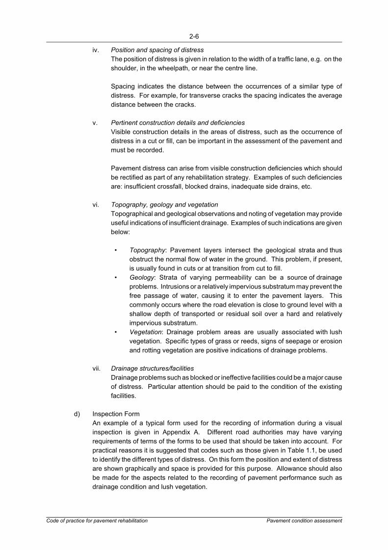
iv. Position and spacing of distressThe position of distress is given in relation to the width of a traffic lane, e.g. on theshoulder, in the wheelpath, or near the centre line.
Spacing indicates the distance between the occurrences of a similar type ofdistress. For example, for transverse cracks the spacing indicates the averagedistance between the cracks.
v. Pertinent construction details and deficienciesVisible construction details in the areas of distress, such as the occurrence ofdistress in a cut or fill, can be important in the assessment of the pavement andmust be recorded.
Pavement distress can arise from visible construction deficiencies which shouldbe rectified as part of any rehabilitation strategy. Examples of such deficienciesare: insufficient crossfall, blocked drains, inadequate side drains, etc.
vi. Topography, geology and vegetationTopographical and geological observations and noting of vegetation may provideuseful indications of insufficient drainage. Examples of such indications are givenbelow:
� Topography: Pavement layers intersect the geological strata and thusobstruct the normal flow of water in the ground. This problem, if present,is usually found in cuts or at transition from cut to fill.
� Geology: Strata of varying permeability can be a source of drainageproblems. Intrusions or a relatively impervious substratum may prevent thefree passage of water, causing it to enter the pavement layers. Thiscommonly occurs where the road elevation is close to ground level with ashallow depth of transported or residual soil over a hard and relativelyimpervious substratum.
� Vegetation: Drainage problem areas are usually associated with lushvegetation. Specific types of grass or reeds, signs of seepage or erosionand rotting vegetation are positive indications of drainage problems.
vii. Drainage structures/facilitiesDrainage problems such as blocked or ineffective facilities could be a major causeof distress. Particular attention should be paid to the condition of the existingfacilities.
d) Inspection FormAn example of a typical form used for the recording of information during a visualinspection is given in Appendix A. Different road authorities may have varyingrequirements of terms of the forms to be used that should be taken into account. Forpractical reasons it is suggested that codes such as those given in Table 1.1, be usedto identify the different types of distress. On this form the position and extent of distressare shown graphically and space is provided for this purpose. Allowance should alsobe made for the aspects related to the recording of pavement performance such asdrainage condition and lush vegetation.

2-7
Code of practice for pavement rehabilitation Pavement condition assessment
Pavement Surveillance MeasurementsThe need to obtain any additional information such as riding quality or deflection bowlmeasurements through routine, non-destructive surveys of the pavement is determined by thedetail and volume of information uncovered by the preliminary investigation. Enoughinformation must be collected to allow for the confident division of the pavement into uniformsections taking into account both its functional and structural parameters.
Riding quality, rut depth and skid resistance measurements are used for assessing theserviceability (functional aspect) of a pavement. Deflection, deflection bowl parameters,Dynamic Cone Penetrometer (DCP) and rut depth measurements are used to assess thestructural capacity of a pavement. Data representative of both the main groups (functional andstructural) should be used in the condition assessment of the pavement. The test frequencydepends on a number of factors such as the:
� Type of test � The variation in the pavement property to be measured � Road category which will determine the level of service and the accuracy required � Statistical properties (e.g. distribution) of the measurements � The length of the road sections to be evaluated.
The number of tests should be sufficient to ensure that conclusions are made with confidence.
2.2.3 Data ProcessingGeneralFor the effective evaluation of the condition of the pavement the collected data must be judgedagainst set criteria and presented in a form that facilitates analytical comparison. It is thereforenecessary to establish and use appropriate performance criteria for each type of measurement.
Much experience has been gained over the years in the actual measurement and recording ofsome of these parameters and this has resulted in the establishment of empirical relationships.The criteria recommended in this document are based on studies of these relationships andothers established overseas, as well as on limits accepted in general practice. Whereverpossible, however, the criteria should be modified to suit local conditions.
Performance Criteriaa) General
Depending on the parameter under investigation, performance criteria could depend onthe category of road (importance and traffic loading), the pavement structure and thedrainage (moisture regime) of the pavement. Criteria have been established for threecondition classifications, i.e. sound, warning and severe, the definition of which dependson the parameter under investigation.
For functional aspects, the criteria refer to acceptability of the pavement in terms ofexisting distress (e.g. cracking, deformation, etc.) as recorded during the detailed visualinspection:
� Sound condition: adequate condition � Warning condition: uncertainty exists about the adequacy of the condition � Severe condition: inadequate condition.

2-8
Code of practice for pavement rehabilitation Pavement condition assessment
For structural aspects, such as measured pavement or pavement layer response, thecriteria refer to the expected future performance of the pavement:
� Sound condition: the measured or recorded parameter is of such a magnitude thatthe pavement should be able to carry the design traffic for the specific categoryof road without deteriorating to a warning state (state considered most economicalfor rehabilitation).
� Warning condition: the measured or recorded parameter is of such magnitude thatthe pavement should be able to carry the minimum design traffic, but not themaximum design traffic for the specific category of road, without reaching a criticalstate (the pavement is expected to deteriorate to a level between a warning andsevere state).
� Severe condition: the measured or recorded parameter is of such magnitude thatthe pavement is expected to deteriorate beyond a critical state before theminimum design traffic loading for a specific category of road had been reached.
The following aspects are taken into account in the establishment of appropriateperformance criteria:
i) Category of roadTable 2.2 gives a nominal four category road classification, for which evaluationcriteria are established for A, B and C category roads. Depending on theimportance of D category roads, the criteria for either B or C category roads couldbe used in the analysis of these roads.
Table 2.3: Nominal road categories adopted for pavement rehabilitation design
ROAD CATEGORY1
A B C D
Typical description Major inter-urbanfreeways andmajor rural roads
Inter-urbancollectors and rural roads
Lightly traffickedrural roads,strategic roads
Light pavementstructure, ruralaccess roads
Importance/service level
Very important/very high level ofservice
Important/high level ofservice
Less important/moderate level ofservice
Less important/usually low levelof service
TYPICAL PAVEMENT CHARACTERISTICS
RISK Very low Low Medium High
Approximate designreliability (%) 95 90 80 50
Typical design trafficloading (MESA/lane)*
3 - 30+over 20 years
0.3-10 < 3 < 0.7
Typical pavement designclass**
T5 to T8 T2 to T6 T1 to T4 T1 to T2
Typical daily traffic:(v.p.d.)***
> 3 000 > 500 <1 000 < 300
Typical riding quality:

2-9
Code of practice for pavement rehabilitation Pavement condition assessment
- at construction- terminal condition (PSI)***
4.0 - 4.52.5
3.5 - 4.52.0
3.0 - 4.01.8
2.5 - 3.51.5
- at construction- terminal condition (IRI m/km; mm/m)***
1.2 - 2.24.0
1.5 - 3.04.5
2.0 - 3.55.0
2.5 - 4.05.5
1 Tabulated values are given only as guidance to help select the nominal pavement classification and thereforethe appropriate level for rehabilitation evaluation criteria.
* MESA/lane: million Equivalent Standard Axles/lane** SATCC pavement design catalogue traffic classes*** v.p.d.: vehicles per day**** PSI = Present Serviceability Index, scale 0-5; IRI= International Roughness Index, in mm/m or m/km.
ii) Pavement structuresThe following pavement structures are identified in terms of the materials used inthe base of the pavement:
� Cemented materials � Bituminous-treated materials � Lightly cemented materials � Natural gravel or untreated materials on:
- An untreated subbase - A treated subbase (TSB).
iii) Moisture regimeFor DCP measurements the moisture regime or drainage condition is taken intoaccount. Four conditions are identified, namely:
� A dry moisture regime or good drainage condition (M1) � An optimum moisture regime or average drainage condition (M2) � A wet moisture regime or poor drainage condition (M3) � A soaked moisture regime (M4).
b) Recommended CriteriaPerformance criteria for the evaluation of the data collected on the pavement, visuallyas well as with the aid of instruments, are discussed in detail in Appendix A.
Of particular importance are the recommendations regarding the confidence levels atwhich pavements should be evaluated. It is considered acceptable for a smallpercentage of a length of road to perform unsatisfactorily at the end of the rehabilitationdesign period. This percentage depends on the category of road. The percentile levelsrecommended are given in Table 2.4.

2-10
Code of practice for pavement rehabilitation Pavement condition assessment
Either a) Fn �P80
n, for kN loads
else b) Fn �P
8160
n, for kg loads
Table 2.4: Percentile levels recommended for data processing
Category ofRoad
Length of Road Allowed toPerform Unsatisfactorily At the
End of its Design Life (%)
Percentile LevelsRecommended forData Processing
ABCD
5102050
95908050
Traffic Loadinga) General
The life of a pavement to a certain level of distress is usually expressed in terms of trafficloading. For pavement rehabilitation design purposes, the effect of the various elementswhich contribute to traffic loading is combined in three variables which adequatelydescribe the load applied to the pavement. These variables are the equivalent trafficloading, the rate of accumulation and the frequency of the application. These enable thecumulative number of equivalent Standard Axle loads (ESAs) to be estimated for anygiven period.
The Standard Axle load is normally defined as either an 8160kg or an 80kN single axleload (also sometimes as an 18000lb or 18 kip axle load), and these can be consideredidentical for practical purposes. Other common nomenclatures used elsewhere forequivalent Standard Axle loads are ESALs (Equivalent Standard Axle Loads) or E80s(equivalent 80kN Standard Axle Loads). The simplification of the load variables to asingle load element (cumulative ESAs) is found to produce satisfactory results inpractice.
It should be noted that the Standard Axle is simply a standard unit of measurement,invariably used for determining and characterising pavement performance andbehaviour characteristics under trafficking, which has no relation to any legal axle loadlimits.
b) Traffic load estimates using information from detailed surveysRefer to the SATCC pavement design guide3 or TRH164
Where detailed information about the axle loads of vehicles using a pavement isavailable, such information should be fully utilized. In such cases it is recommended thatthe differences in the reaction of different materials to loading be taken into account.
The formula used for the determination of equivalent traffic is:
...Equation 1

2-11
Code of practice for pavement rehabilitation Pavement condition assessment
� E0( 1�i )n�1
� 1i ( 1�i )n
� E0( 1�j )[( 1�j ) x
� 1]j
where:Fn is the load equivalency factor in ESAs, for exponent n, andP = axle load (in kg or kN)n = relative damage exponent
The value of 4 for the exponent n is often used, in line with early findings and thecommonly cited "fourth-power damage effects" of heavy axle loads. It is now clear thatthe value is influenced by various factors, with the most significant being the pavementconfiguration.
Table 2.5 indicates recommended n values to be used where pavement structures areknown, otherwise a value of 4 should be adopted.
Table 2.5: Recommended relative damage exponents, n5
Pavement base/subbase Recommended n
Granular/granularGranular/cementedCemented/cementedBituminous/granularBituminous/cemented
43
4.544
Equation 1, with appropriate "n" values, can be used with available data to calculate theESAs at any time in the past. These data can then effectively be used to calculate Np
and Nf where:
Np = past cumulative traffic loading
...Equation 2
andNf = expected future cumulative traffic loading
...Equation 3
where:Eo = annual ESAs in the year of investigation
(assume the road will be opened the following year)i = mean historical ESA growth rate during the past
(per cent/100)n = age of the pavement (years)j = expected ESA growth rate during the rehabilitation design period
(per cent/100)x = rehabilitation design period (years)

2-12
Code of practice for pavement rehabilitation Pavement condition assessment
c) Traffic load estimates using traffic countsRefer to the SATCC pavement design guide3 or TRH164
In cases where detailed axle load data are not available, estimations of traffic loadingwill have to be based on traffic count data. This will often be based on the trafficcomposition by vehicle type, or simply the total number of vehicles and the percentageof heavy vehicles.
In such cases various assumptions need to be made to estimate Nf and Np and careshould be taken to allow for seasonal variations in traffic when using such data. Thesecalculations are based on the number of heavy vehicles only, since the damaging effectsof cars and light vehicles is negligible for practical purposes.
Table 2.6 can be used to estimate the ESAs per heavy vehicle configuration, wherespecific local information is not available, but every effort should be made to developlocal factors from traffic and axle load surveys. The likelihood of significant error in usingsuch generic data is high and this must be recognised by the Engineer.
Table 2.6: Estimation of average ESAs per heavy vehicle class
Vehicle classNormal*
conditionsAbnormal*conditions
Typicalrange**
Bus 2-axle large (>35 seats) 0.7 1.2 0.4 - 1.8
Trucks(includingtrailers)
2-axle***3-axle4-axle5-axle6-axle7 or more axles
0.71.71.82.23.54.4
1.52.02.53.24.76.0
0.3 - 2.00.5 - 3.00.7 - 3.51.0 - 4.51.2 - 6.02.0 - 8.0
* Normal: control of overloading; values based on South African experience4
Abnormal: little formal control of overloading; indicator values** Higher values outside this range are commonly reported for overloads*** This class in particular can show very great variation
The table suggests values appropriate in normal conditions (where overloading isminimal, say less than 5 per cent of heavy vehicles) and for abnormal conditions (wherevehicle overloading is a recognised problem). The Engineer is advised to consider bothin order to make a best estimate where any doubt exists about extent of overloading.An even more simplified estimate based only on nominal ESAs per heavy vehicle (ie,regardless of configuration) is not recommended unless sufficient local data is availableto minimise errors, which can be very high otherwise.
The growth rate in ESAs is dependent on the growth rate in traffic volume, the growthrate in heavy vehicles as a percentage of the total traffic volume and the growth rate inESAs per heavy vehicle.

2-13
Code of practice for pavement rehabilitation Pavement condition assessment
ESA growth rate � 1 �h
1001 �
v100
� 1 100
h � ( fp
)1n (1 �
t100
) �1 100
The expected growth rate in ESAs for the specific road can be determined fromEquation 4:
...Equation 4
where:h = heavy vehicle growth ratev = ESA/vehicle growth rate
The heavy vehicle traffic growth rate, h, can be calculated from Equation 5:
...Equation 5
where:f = future percentage heavy vehiclesp = present percentage heavy vehiclesn = time periodt = total traffic growth rate
Taking these factors into account, it is recommended that a low, average and highestimate be calculated by combining the low, probable and high estimates of the totaltraffic growth rate, the change in the percentage heavy vehicle and the ESA/vehiclegrowth rate. These permutations will give the range of ESA growth rates that is possiblefor a specific road. The cumulative past and future ESA ranges can be determined aspreviously shown in Equations 2 and 3.
2.2.4 Pavement Evaluation and Initial Structural Capacity Analysis of Uniform SectionsPavement EvaluationAll information gathered on the road is taken into account when dividing it into uniformpavement sections. It follows that the information needs to be combined in an easilyunderstood and manageable format. Examples of such a procedure are given in Appendix A.The processed data for a number of kilometres of road should be summarised to facilitate easyinterpretation for the identification of uniform pavement sections.
The identified uniform pavement sections need to be divided according to their overall needinto the following categories:
� Requiring no action � With only surfacing problems � With localized problems � Requiring probable structural strengthening in terms of life in ESAs.
Based on this classification, and using the traffic loading estimates (of what has been carried,and what is expected over the rehabilitation design period), a rating system for the urgency oftreatment is recommended. This can assist in prioritisation when a number of potentialrehabilitation projects have been identified. Such a prioritisation rating system must, however,be established locally to suit specific prevailing conditions and budgetary constraints.

2-14
Code of practice for pavement rehabilitation Pavement condition assessment
a) Sections with No Significant ProblemsSections with no significant problems are those which can be economically kept withinacceptable levels of serviceability by routine maintenance for the medium term, typically8-10 years. Such sections are often found between the distressed sections which haveprompted the investigation, and can be excluded from further analysis.
However, because of the variable nature of distress, care should be taken to determinethat the sections do in fact differ significantly from the others and that distress in themis not just being delayed for some reason (the results of the structural capacity analysisare of particular importance).
b) Sections with Obvious Surfacing-only ProblemsThese are sections where the distress obviously occurs only in the surfacing, and is inno way caused or aggravated by inadequacies in the underlying pavement structure orsubgrade.
Distress solely related to the properties of the surfacing can take the form of:
� Deformation � Disintegration or ravelling � Cracking � Loss of skid resistance through bleeding or polishing.
In the absence of other forms of distress, areas exhibiting ravelling, polishing orbleeding, can be classified as having surfacing-only problems.
In the case of cracking and/or deformation, however, further detailed testing andanalyses are invariably necessary before one can be confident that these are in factsurfacing-only problems.
c) Sections Showing Localized DistressSections with localized distress are short (normally less than 200 m) but in clearly poorercondition than the adjacent sections. The identification of sections where localizedfactors are the cause of distress is important for two main reasons:
� To prevent an erroneous under-assessment of the overall structural capacity ofthe road, which will lead to unnecessary or excessive rehabilitation.
� To prevent the application of rehabilitation measures which do not deal with thecauses of localized distress and will result in a recurrence of the distress.
Almost invariably, the main cause of localized distress on rural roads is inadequatesurface and subsurface drainage. Poor drainage allows water to accumulate in thesubgrade and pavement layers, which ultimately results in a reduction of the strengthand load-spreading ability of the layers affected.
Specific attention must be given during the condition assessment to the identification ofthese sections, which can usually be verified from the:
� Condition of surface drains � Topography and geology of the surrounding area � Vegetation in the immediate area

2-15
Code of practice for pavement rehabilitation Pavement condition assessment
which in turn can confirm the likelihood of excess moisture as the cause of distress.
During the visual inspection, or as a result of such an inspection, any additionalinformation or clues about the cause and mechanism of localized distress mustnevertheless be recorded. Further detailed investigation may still be required toestablish the exact cause and mechanism of distress for any locally affected area.
d) Sections Where Structural Improvement May Be RequiredThese sections are those which, after the initial assessment, do not fit into any of theprevious categories or about which there is still uncertainty as to the exact nature of thedistress. They may or not be structurally inadequate but will require further analyses.These sections are dealt with in the detailed assessment phase of the conditionassessment.
During the initial assessment, however, an attempt should be made to indicate thenature and urgency of the problem and the nature of more detailed and/or additionaltesting that should be done on these sections during the next phase of an investigation.
Naturally, further detailed testing may well identify some of the sections as exhibitingonly localized distress or surfacing-only problems.
Initial Structural Capacity Analysisa) General
The objective of the structural capacity analysis is to determine the remaining life (if any)of the existing pavement, i.e. the number of ESAs it will still be able to carry before itreaches a critical level of distress. This is particularly relevant where non-strengtheningrehabilitation measures appear appropriate, or when a high increase in traffic loading isanticipated.
The capacity analysis will determine the possible distress of the pavement throughnormal traffic-induced forces during the rehabilitation design period. Where failure islikely during this period, the pavement section should be identified as needing structuralstrengthening.
Various pavement analysis methods may be used to determine the pavement'sstructural capacity. At the condition assessment phase of a rehabilitation investigationit is recommended that the structural capacity of the pavement be determined using asimple, empirically-derived relationship. A more detailed and/or sophisticated analysisof the pavement sections will be done during the rehabilitation design phase of theinvestigation.
Although any applicable method may be used to determine the structural capacity of theuniform pavement sections, three methods based on different pavement measurementsare summarized. These are based on the following parameters:
� Surface deflection � Dynamic Cone Penetrometer (DCP) measurements � California Bearing Ratio (CBR)

2-16
Code of practice for pavement rehabilitation Pavement condition assessment
These methods are empirically-based and have limitations in their applicability. Beforeusing any of these methods, users are referred to Appendix B, where the assumptions,limitations and advantages of these methods are discussed in more detail.
b) Methods Based on Surface Deflection MeasurementsThe use of deflection measurements to assess future pavement behaviour has been wellestablished throughout the world, largely due to the availability of deflection measuringdevices in most countries. The deflection method recommended for use is the methoddeveloped at the Transport Research Laboratory (TRL) in England6. This method takesinto account the type of base material in the prediction of remaining life, but is applicableonly to a maximum of 10 million ESAs.
This method is based on the standard measurement of deflections using the BenkelmanBeam (as described in the CSIR Manual K167). Measurements taken with any otherinstrument or using any other procedure should be converted to standarddeflections measured with the Benkelman Beam. Care should be taken with suchconversions since relationships between instruments could depend on variables suchas the type of pavement.
The design graphs in Figures 2.2 - 2.5 are used to predict the remaining life in term ofESAs to a rut depth of 10 mm respectively for pavements containing:
� Non-cemented granular bases � Aggregates exhibiting a natural cementing action � Bitumen-bound bases � Cement-bound bases
Figure 2.2: Relationship between standard deflection and life: granular road bases

2-17
Code of practice for pavement rehabilitation Pavement condition assessment
Figure 2.3: Relationship between standard deflection and life: granular road bases with naturalcementing action
Figure 2.4: Relationship between standard deflection and life: bituminous road bases

2-18
Code of practice for pavement rehabilitation Pavement condition assessment
Figure 2.5: Relationship between standard deflection and life: cement-bound road bases
Selection of the appropriate chart takes place on the basis of the type of material usedin the pavement structure. A pavement is classified as having a cement-bound base ifmore than 100 mm of such material is present in the pavement structure, even if locatedbeneath a considerable thickness of bituminous surfacing and roadbase material.
Similarly, a pavement is classified as having a bitumen-bound base when more than150 mm of bituminous material is present in the pavement structure (provided that thereis not more than 100 mm of cement bound material present).
The bituminous layers may be separated by layers of granular material. A pavement isclassified as having a granular base with natural cementing action when more than150 mm of this material is present in the pavement structure (provided that anycement-bound layer is less than 100 mm thick and that less than 150 mm ofbituminous-bound layers is present in the pavement). If none of the above applies, thepavement is classified as having a granular road base.
Some restrictions apply to the use of the chart for pavements with more than 100 mmof cement-bound materials. The performance of pavements with cemented layers coulddepend on deterioration associated with shrinkage cracking reflected from the cementedlayers. For this reason the normal critical curve for cumulative loading (in excess of10 million ESA) only applies to pavements with a bituminous cover of more than175 mm. As shown by the broken line in Figure 2.5, the expected life (in terms of trafficloading) of these pavements with thinner surfacings is much reduced.
Maximum surface deflections will not give a good indication of expected life ofpavements with cement-bound layers under the following conditions:

2-19
Code of practice for pavement rehabilitation Pavement condition assessment
i. When a structural weakness is present in the top cemented layer (in thiscase deflections are kept relatively low by the presence of an undamagedlower cement layer), and
ii. With weak cemented materials where the aggregate grading has littlemechanical stability (low deflections may be present in early life butcracking leads to early disintegration).
With the surface deflection, the past cumulative ESAs and the type of pavement known,the charts in Figures 2.2 to 2.5 are used to estimate the residual life of the pavement, asillustrated in Figure 2.6 with the following data:
Type of pavement: granular base with aggregates exhibiting a natural cementedaction
Past traffic load : 3 million ESAStandard deflection : 0,38 mm (80 kN single axle load).
From Figure 2.6, the expected residual life = 11 million - 3 million ESA = 8 million ESA
Figure 2.6: Design example for pavements with granular road bases whose aggregates exhibita natural cementing action (from Figure 2.3)
2-20
Code of practice for pavement rehabilitation Pavement condition assessment
Deflection basin parameters calculated from Falling Weight Deflectometer (FWD)measurements as discussed in Appendix A, can also be used to obtain an indication ofthe structural capacity of uniform pavement sections.
c) Method Based on DCP MeasurementsThe Dynamic Cone Penetrometer (DCP) has been used for a number of years insouthern Africa as a non-destructive testing (NDT) device to measure the in situbearing capacity of pavements. The method used to analyse the bearing capacityof pavements using DCP measurements as described in this document, wasdeveloped in South Africa at the then Transvaal Roads Department8.
The DCP measures the penetration per blow into a pavement through all thedifferent pavement layers. This penetration is a function of the in-situ shearstrength of the material. The penetration-depth profile gives an indication of thein-situ properties of the materials in all the pavement layers up to the depth ofpenetration which is normally 800 mm for road pavements.
The total number of blows required to penetrate the pavement layers to a depthof 800 mm (DSN800), for a reasonably balanced pavement, is used in Figure 2.7to determine the bearing capacity of the pavement to a rut depth of 20 mm.
The existing rut depth on the pavement section and the past cumulative trafficloading that has used the road since construction should be taken into account incalculating the remaining "life" of the pavement.

2-21
Code of practice for pavement rehabilitation Pavement condition assessment
Figure 2.7: Relationship between pavement bearing capacity and DSN800
d) Methods based on CBR measurementsThe analysis is based on the measurement of the soaked CBR of the subgrade9. It isrecommended that at least one CBR test be done every 500 m. The Design SubgradeStrength (DSS) value is defined as the subgrade strength value that is equal to or lessthan approximately 90 per cent of all test values (minimum of five tests recommended)in a section.
The representative effective thickness (Te) of the pavement layers above the subgradeis then determined, as outlined below, to estimate pavement bearing capacity.
The effective thickness of the existing pavement is defined as the equivalent thicknessof full-depth asphalt that would have the same strength as the total of the pavementlayers above the subgrade of the existing pavement.
Te is calculated by taking into account the type of material and condition of each of thepavement layers. For the different materials the following information is important:

2-22
Code of practice for pavement rehabilitation Pavement condition assessment
Te � �n
i�1fi ti
� Granular material: thickness of material and classification as base, subbase orimproved subgrade quality material
� Asphalt material: thickness, type and condition of layer � Cemented materials: thickness, condition and support of the layer.
The representative effective thickness (Te) is then determined from Equation 6:
...Equation 6
whereti = thickness of the i th layerfi = conversion factor of the i th layer (from Table 2.7)n = number of pavement layers above the subgrade
The evaluation of the condition of the pavement layers is done subjectively. Conversionfactors (f) for each of the pavement layers above the subgrade are given in Table 2.7.
The DSS, together with Te, is used in Figure 2.8 to get an indication of the remaining lifeof the pavement.

Table 2.7: Converting thickness of existing pavement components to Effective Thickness9
Classificationof material Description of material Conversion
factors
I Native subgrade in all cases. 0
II a. Improved subgrade. Predominantly granular materials - may contain some silt and clay but have PI of 10 or lessb. Lime modified subgrade constructed from high-plasticity soils - PI greater than 10. 0.0 - 0.2
IIIa. Granular subbase or base - Reasonably well-graded, hard aggregate with some plastic fines and CBR not less than 20, use upper
part of range if PI is more than 6. b. Cement modified subbase and bases constructed from low plasticity soils - PI of 10 or less
0.1 - 0.3
IV
a. Granular base - Non-plastic granular material complying with established standards for high quality aggregate base. Use upper partof range.
b. Asphalt surface mixtures having large well defined crack patterns, spalling along the cracks, exhibit appreciable deformation in thewheel paths showing some evidence of instability.
c. Portland cement concrete pavement that has been broken into small pieces, two feet or less in maximum dimension, prior to overlayconstruction. Use upper part of range when subbase is present; lower part of range when slab is on subgrade.
d. Soil-cement bases that have developed extensive pattern cracking, as shown by reflected surface cracks, may exhibit pumping, andpavement shows minor evidence of instability.
0.3 - 0.5
V
a. Asphalt surfaces and underlying asphalt bases** that exhibit appreciable cracking and crack patterns, but little or no spalling alongthe cracks, and while exhibiting some wheel path deformation, remain essentially stable.
b. Appreciably cracked and faulted Portland cement concrete pavement that cannot be effectively undersealed. Slab fragments,ranging in size from approximately one to four square yards, are well seated on the subgrade by heavy pneumatic rolling.
c. Soil-cement bases that exhibit little cracking, as shown by reflected surface crack patterns, and that are under stable surfaces.
0.5 - 0.7
VI
a. Asphalt concrete surfaces that exhibit some cracking, small intermittent cracking patterns and slight deformation in the wheel pathsbut remain stable.
b. Liquid asphalt mixtures that are stable, generally uncracked, show no bleeding, and exhibit little deformation in the wheel paths.c. Asphalt treated base, other than asphalt concrete.**
d. Portland Cement concrete pavement that is stable and undersealed has some cracking but contains no pieces smaller that about onesquare m.
0.7 - 0.9
VIIa. Asphalt concrete, including asphalt concrete base generally uncracked, and with little deformation in the wheel paths.b. Portland cement concrete pavement that is stable, undersealed and generally uncracked. 0,9 - 1,0c. Portland cement concrete base, under asphalt surface that is stable, non-pumping and exhibits little reflected surface cracking.
0.9 - 1.0
* Values and ranges of Conversion Factors are multiplying factors for conversion of thickness of existing structural layers to equivalent thickness of asphalt concrete.** Asphalt concrete base, asphalt macadam base, plant-mix base, asphalt mixed-in-place base.

2-24
Code of practice for pavement rehabilitation Pavement condition assessment
Figure 2.8: Thickness requirements for asphalt pavement structures using subgrade soil CBR9

2-25
Code of practice for pavement rehabilitation Pavement condition assessment
2.3 Detailed Assessment
2.3.1 Objectives and Scope The detailed assessment deals with lengths of road that have been identified as probablyrequiring structural improvement. The aim is to obtain sufficient knowledge about the lengthof pavement to enable a confident decision to be taken on the rehabilitation strategy to befollowed. This is accomplished by:
� The determination of the cause and mechanism of distress in each uniform pavementsection.
� A description of the pavement situation as represented by each uniform pavementsection.
The cause and mechanism of distress of a pavement is an important aspect of the pavementsituation which may not be known at this stage of the investigation. To identify, withconfidence, the cause and mechanism of distress of each uniform section, full use should bemade of experience of pavement behaviour and distress manifestations and of all availableresults of tests and information gained during the initial assessment, before embarking on anyfurther investigation.
The accurate description of the pavement situation which includes the pavement material,loading, environmental and distress conditions, will assist greatly in the correct analysis andrehabilitation design of each pavement section.
The investigation procedure for the detailed part of the condition assessment is outlined inFigure 2.9.
2.3.2 Cause and Mechanism of DistressGeneralThe understanding of the behaviour of a pavement is the key to the identification of the originand, hence, the cause and mechanism of distress. Where distress is manifested in a expectedmanner and this has been observed during the initial assessment, the cause and mechanismof distress and hence the pavement situation may be easy to verify. In this case no furthertesting may be required before embarking on the selection of applicable rehabilitation designmethods and the design of the structural strengthening needed.
However, when doubt exists about the exact cause and mechanism of distress, analyticalprocedures and tests should be used to confidently determine the cause and mechanism ofdistress. Information gained during the initial assessment (e.g. pavement type and observeddistress) is used to identify the possible causes of distress. Empirical manipulations of data,such as DCP penetrations, deflections, rut depth and traffic could, for example, give anindication of the most probable cause of distress. Confidence to proceed with the rehabilitationinvestigation is gained by verifying the probable cause and mechanism of distress withappropriate tests.

2-26
Code of practice for pavement rehabilitation Pavement condition assessment
Figure 2.9: Flow diagram of pavement detailed assessment as part of the conditionassessment
If the tests do not confirm what was expected, the process must be repeated, but only if moreinformation is likely to change the decision on the rehabilitation strategy to be adopted.

2-27
Code of practice for pavement rehabilitation Pavement condition assessment
More tests may be needed and this cycle is repeated (as shown in Figure 2.9) until the causeof distress can be positively identified, or until it becomes apparent that more information willhave little effect on the decision. With the cause of distress confidently determined, thepavement situation can be defined for each uniform section and used to select applicablerehabilitation design methods for the next phase of the rehabilitation investigation.
Various pavement tests can be used during the detailed assessment phase of an investigationfor the structural evaluation of a pavement, and these are summarised in Table 2.8. Forcompleteness, the Table includes several methods well established in South Africa but notcurrently widely used yet in other SATCC States.
Pavement Behavioura) General
Pavement behaviour is a function of the initial as-built composition of the pavement, theload carried by the pavement and the environment in which it operates. The categoryof the pavement, as shown in Table 2.3, which depends on the importance of the roadin terms of the traffic loading, road function, etc., can give a good initial indication of theoriginal strength of the pavement.
In addition to the original strength, pavement behaviour is controlled by the behaviourof the materials in the various pavement layers. In this regard, the type and behaviourof the material in the base course of the pavement is of particular importance, becauseit:
� Is close to the surface of the road and distress in the base is often reflected on thesurface of the road.
� Has little protection in terms of materials covering the layer and hence, a relativelyhigh quality material with good load-bearing characteristics is usually requiredfrom the base layers.
Consequently pavements are often described in terms of the materials contained in thebase of the pavement, which is the primary distinction used later in evaluating pavementbehaviour.
Under the action of traffic and the environment, the materials in the various pavementlayers may change with time. Usually by the time of the rehabilitation investigation, forexample, treated layers could have broken down and should rather be classified andanalysed as granular layers (termed equivalent granular layers).
b) Pavement BalancePavement balance may be described as the relative relationship between the loadbearing properties of adjacent pavement layers. When the characteristics of the layersare such that a gradual change in these properties throughout the pavement structureis present, resulting in relatively low stress or strain concentrations, the pavement isconsidered to be in balance. However, when adjacent layers have vastly differentstiffness characteristics, a sudden change in the load bearing properties of the layer inthe pavement is present, resulting in high stress or strain concentrations. Such apavement is considered as poorly-balanced, with the implication that the behaviour maybe less predictable since the load bearing properties of an overstressed layer maychange significantly.

BEN
KELM
AN B
EAM
DEF
LEC
TOG
RAP
H
FALL
ING
WEI
GH
T D
EFLE
CTO
MET
ER (F
WD
)
DYN
AMIC
CO
NE
PEN
ETR
OM
ETER
(DC
P)
MAT
ERIA
L TE
STS
(DES
TRU
CTI
VE)
DEH
LEN
CU
RVA
TUR
E M
ETER
RO
AD S
UR
FAC
E D
EFLE
CTO
MET
ER (R
SD)
MU
LTI-D
EPTH
DEF
LEC
TOM
ETER
(MD
D)
CR
ACK
ACTI
VITY
MET
ER (C
AM)
HEA
VY V
EHIC
LE S
IMU
LATO
R (H
VS)
HVS
+ IN
STR
UM
ENTS
Table 2.8: Summary of measurements most commonly used during a detailed assessment
PAVEMENT PROPERTY
TESTS
STRUCTURALEVALUATION
Generally available Surface Elastic Deflection X X X X X X
Surface Deflection Bowl X X X X X X
Component (Material) analysis X X X
More specialisedmeasurements
(instrumentsdeveloped andused in SouthAfrica)
In Depth Deflections X X
In Depth Deformation X X
Crack Movement X X
Pavement Behaviour underAccelerated Loading
X X

2-29
Code of practice for pavement rehabilitation Pavement condition assessment
Poorly balanced pavements usually contain layers which are relatively stronger orweaker in terms of the rest of the pavement. If these layers can be identified, from aDCP survey say, the potential influence of such layers on the overall behaviour of thepavement can then be assessed. Poor balance is almost invariably associated with theuse of cemented material, especially for the subbase, and the stress concentrations inthis relatively stiff layer can lead to breakdown (equivalent granular condition).
The concept of pavement depth is also useful in assessing likely behaviour. Pavementsidentified as shallow structures have most of their relative strength concentrated in thetop of the pavement structure and usually consist of one or two thin, strong and relativelyrigid top layers and supporting layers of which the strength support declines sharply withdepth. In contrast, deep pavement structures consist of a number of layers of similarstrength with depth. This can be of importance in confirming the mode of failure in apavement.
c) Pavement StatePavements may go through various phases describing changes in behaviour and hencepavement condition, and usually a pavement will change from a stiff to a more flexibletype of pavement. Surface deflections (or deflection bowl parameters, as discussed inAppendix A) provide the basis for this classification as given in Table 2.9.
Table 2.9: Nominal pavement state from deflection
Behaviour Deflection(mm)*
Very stiffStiffFlexibleVery flexible
< 0.20.2-0.40.4-0.6> 0.6
* Maximum Benkelman beam deflection under standard wheelload
d) Material statePavement behaviour is controlled by the behaviour of the materials in the various layers.In considering general trends in the behaviour of pavements containing differentpavement materials, it must be remembered that the state of the materials change withtime.
Consequently, the general trends in behaviour which are discussed refer to the original,as-built state of the material. The state of materials in a pavement under investigationmay differ considerably from the original as-built state, with obvious examples beingcracked or wet material.
i) Granular pavement layersThe general trends in behaviour of granular layers in terms of deformation and theeffective dynamic modulus of the layer, are illustrated in Figure 2.10. It is seenthat in the initial phase of the behaviour some deformation occurs in the wheeltracks.

2-30
Code of practice for pavement rehabilitation Pavement condition assessment
Figure 2.10: Nominal behaviour of pavement layers constructed with granular materials
This deformation is usually referred to as post-construction deformation, duringwhich the layer further densifies under the action of traffic. It follows that theeffective strength or bearing capacity of the layer may improve during this phaseand an increase in the effective dynamic modulus of the layer may occur.
Bearing capacity is, inter alia, a function of density, shear strength, moisture, etc.The amount of post-construction compaction depends on the bearing capacity(density, strength) of the layer achieved during the construction of the layer, andthe quality of the layer. The higher the specified level of compaction, the lower theexpected initial densification.

2-31
Code of practice for pavement rehabilitation Pavement condition assessment
Following a phase of initial densification (traffic moulding), the layer usually entersa stable phase during which little deformation occurs (depending on the bearingcapacity).
The rate of increase in deformation during this phase depends on the initial qualityof the material. The effective elastic modulus may show some change as a resultof an adjustment in the balance of the pavement which may occur under theaction of traffic loading. Layers with a relatively high strength within the pavementstructure may de-densify, while relatively weak layers may show some increasein strength, due to densification (traffic moulding).
Untreated sub-layers usually fail when the shear strength of a layer is exceeded.Where the initial quality of the material is poor with a resultant low bearingcapacity, high traffic loadings may result in quick shear failure of the layer andPhase 2 in the behaviour of the layer, as illustrated in Figure 2.10, may be veryshort or even non-existent.
In Phase 3, the layer shows an increase in the rate of deformation and a relativelyquick decrease in its effective elastic modulus. This may be caused by anincrease in moisture content (cracking of surface and ingress of water through theopen cracks) resulting in a sudden decrease in bearing capacity and/or shearfailure of the material.
ii) Light cementitious pavement layersPavement layers consisting of lightly cementitious materials may behave in twodistinctly different ways. When most of the strength of the pavement isconcentrated in the cement-treated layers (shallow pavement), the layer usuallyfails in tension. In such cases, the behaviour of the layer is similar to thebehaviour of relatively strong cement-treated layers.
In cases where the strength of the pavement is distributed in depth through thepavement (deep structure), the lightly cementitious layer may fail due to crushingof the top of the layer. The general trends in behaviour of such layers in terms ofpavement deformation and the effective elastic properties of the layers, areillustrated in Figure 2.11.
During the initial phase of behaviour the layer is still intact and shows littledeformation and a relatively high effective elastic modulus. However, crackingmay develop relatively early and the first phase of the behaviour as illustrated inFigure 2.11, may be very short, or even non-existent.
With the development of cracks at the top of the layer, the compressive strengthof the layer is exceeded and crushing of the layer takes place. This phase ofbehaviour is characterised by a rapid reduction in the effective elastic modulus ofthe layer and an increase in the rate of deformation as shown in Figure 2.11.
The crumbling of the layer continues until the layer is completely broken down.The layer is then in an equivalent granular state and behaves as a granular layer.

2-32
Code of practice for pavement rehabilitation Pavement condition assessment
Figure 2.11: Nominal behaviour of lightly cemented pavement layers in a deep structure
Iii) Cement-treated Pavement LayersGeneral trends of behaviour of relatively strong, cement-treated layers in termsof permanent deformation and effective elastic modulus are shown in Figure 2.10.Most of the strength of a pavement with cement-treated layers is usuallyconcentrated in these layers. As a result, these layers usually fail in tension(fatigue).
Initially, the cement-treated layer will show virtually no increase in rut depth andthe layer will have a relatively high effective elastic modulus. Typical blockcracking (spacing 4-5 m), due to shrinkage, may develop early in the life of the

2-33
Code of practice for pavement rehabilitation Pavement condition assessment
pavement and will most probably reflect through to the surface of the pavementif the layer is not isolated from the surface by granular layers.
In some cases, even this may not prevent the cracks from reflecting through to thesurface of the road. If water is prevented from entering through these cracks, theshrinkage cracking will have no or little effect on the future behaviour of thepavement and the pavement will still be in a state of behaviour similar to thepre-cracked phase as shown in Figure 2.12.
However, as a result of fatigue from trafficking and the relative weakness ofcement in tension, many cement-treated layers soon develop micro-cracks.These cracks result in a reduction of the effective elastic modulus of the layer.The layer will still appear intact (the large blocks caused by shrinkage cracking)and the rate of deformation (rutting) will still be low.
The development of micro-cracks will continue up to a point where the layerbreaks down into a granular state. The breaking down of the layer usuallyhappens relatively quickly. The layer now has little resemblance to the initialcement-treated layer. The behaviour of the layer is now similar to that of agranular layer as discussed previously. The quality of this equivalent granularlayer is usually somewhat better than the quality of the virgin material used toconstruct the cement-treated layer.
Some variations in the behaviour of cement-treated materials may occur.Depending on the pavement composition, the point of maximum tension may notbe situated at the bottom of the layer. In such cases, a crack may develop withinthe layer and part of the layer (usually the upper part) may break up long beforethe rest of the layer. In this case the top part of the cement-treated layer will forma weaker equivalent granular inter-layer.
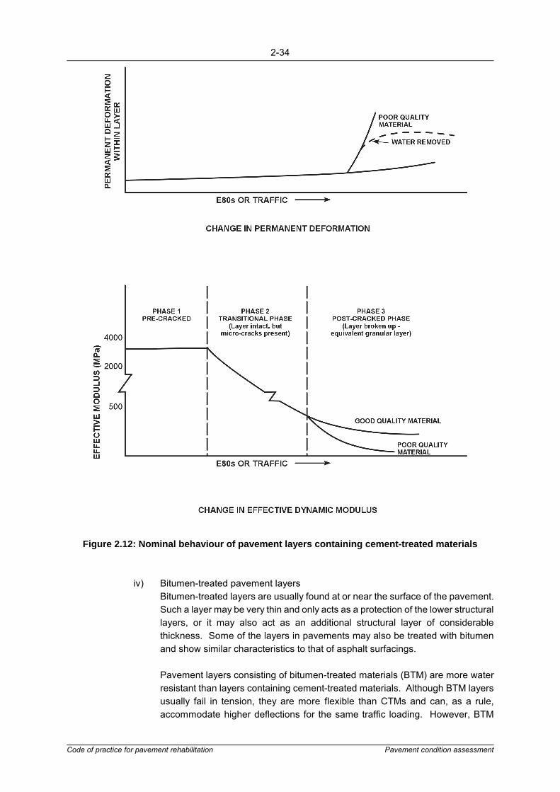
2-34
Code of practice for pavement rehabilitation Pavement condition assessment
Figure 2.12: Nominal behaviour of pavement layers containing cement-treated materials
iv) Bitumen-treated pavement layersBitumen-treated layers are usually found at or near the surface of the pavement.Such a layer may be very thin and only acts as a protection of the lower structurallayers, or it may also act as an additional structural layer of considerablethickness. Some of the layers in pavements may also be treated with bitumenand show similar characteristics to that of asphalt surfacings.
Pavement layers consisting of bitumen-treated materials (BTM) are more waterresistant than layers containing cement-treated materials. Although BTM layersusually fail in tension, they are more flexible than CTMs and can, as a rule,accommodate higher deflections for the same traffic loading. However, BTM
2-35
Code of practice for pavement rehabilitation Pavement condition assessment
layers are visco-elastic in behaviour and hence temperature susceptible, and maydeform under high temperatures and high wheel loads.
General trends in the behaviour of bitumen-treated pavement layers in terms ofpermanent deformation and the effective elastic modulus of the layer are shownin Figure 2.13.
Bitumen-treated layers usually show a general increase in deformation under theaction of traffic from the time of construction. The rate of deformation of the BTMlayer is strongly dependent on the properties of the mix, especially the grading ofthe aggregate. The rate of deformation may decrease with time because of anincrease in the stiffness of the binder in the layer due to ageing. However, anincrease in the stiffness of the mix will make the mix more prone to fatigue and,thus, cracking.
Cracking usually starts at the bottom of the layer. However, the point of maximumstrain does not always occur at the bottom of the layer and cracking may also startat a point within the layer or at the top of the layer. Low temperatures, resultingin a relatively high modulus at the top of the asphalt layer, together with thesurface effect of ageing, may result in the quick development of cracking at thetop of the BTM layer. Cracking will result in a decrease in the general effectivemodulus of the layer.
At the end of the fatigue life of the BTM layer, it will break down to a granular statewhich has little resemblance to the original layer. At this stage, behaviour of thelayer below the surfacing is similar to that of a granular layer. The quality of theequivalent layer strongly depends on the quality of the original BTM. Similar togranular materials an initial densification will also take place before the rate ofdeformation reduces.
The addition of low percentages (1 to 3 per cent) of bitumen-emulsion, with orwithout the addition of other stabilising agents, forms the basis for theconstruction of emulsion-treated layers. These layers are usually constructed assub-layers and have similar qualities to BTM layers, including:
� High resistance to water � Highly flexible � Tolerance towards high deflections under conditions of relatively high traffic
loading without showing excessive deformation.

2-36
Code of practice for pavement rehabilitation Pavement condition assessment
Figure 2.13: Nominal behaviour of pavement layers with bitumen-treated materials
Distress Manifestationsa) General
The mode (cracking and/or deformation) and type of distress can often indicate the needfor structural strengthening. Cracking and/or deformation can originate in any of thepavement layers or subgrade.
The type of distress can provide valuable input for the identification of a problem in anyuniform pavement section. Hence, the recognition of these visual indicators of problemsare helpful in the condition assessment of the road.

2-37
Code of practice for pavement rehabilitation Pavement condition assessment
b) Deformationi. Deformation caused by surfacing inadequacies or problems
Premature rutting or corrugations may be caused by surfacing problems only,since under certain conditions asphalt layers may deform. In the analysis, nocorrelation between rutting and maximum deflection will be found and a DCPsurvey will show good shear strength in the base or subbase layers.
Although heavy traffic loadings, high temperatures and steep gradients associatedwith tight curves are contributing factors, deformation of asphalt layers is usuallyassociated with a lack of creep resistance of the mixture.
Normally surface treatments do not deform; however, shear may take place. Thisis easily identified during the visual inspection. These and other unusualsurfacing conditions are dealt with in TRH310.
ii. Deformation caused by base or subbase inadequaciesDeformation of the subbase and base layers is normally associated with sheardisplacement or densification of the material. Displacement occurs when theshear stresses imposed by traffic exceed the shear strength of the pavementlayers. Overstressing is normally attributed to layers being of inadequate qualityunder the prevailing conditions, and results in the heaving of the surface next tothe wheel tracks. Shear or plastic deformation results in heaving of the surfaceadjacent to the wheel paths with associated cracking. Rutting is usually confinedto the wheel path itself.
Careful observation during the visual inspection should enable base or subbaseshear to be identified through these characteristic manifestations. The width ofrutting gives an indication of the position of shear failure; the wider the rut, thedeeper the failed layer.
A DCP survey is often useful to get an indication of the extent and position ofdistress in any layer(s) of the pavement, particularly if the layers are granular. Forbituminous layers, creep tests may be more appropriate.
iii. Deformation caused by post-construction densification of materialFurther densification of the subgrade and pavement layers can occur under theaction of traffic. As in subgrade associated deformation, usually no heave occurson the surface and rutting is quite uniform in the longitudinal direction.
The structural capacity of pavements with shear failure compared with thepavements showing signs of post-construction densification is very different. Inthe case of shear, the structural capacity will decrease, and deformation willincrease if the pavement is not rehabilitated. In the case of post constructiondensification, the pavement increases its structural capacity during trafficking andtends towards a stable condition.
A DCP survey in areas between ruts may, if compared with results in the wheelpath, give an indication of whether densification has occurred.

2-38
Code of practice for pavement rehabilitation Pavement condition assessment
iv. Deformation originating in the subgrade (traffic associated)Overstressing of the subgrade by traffic loads is generally attributed to insufficientload distribution by the pavement layers because of inadequate pavementthickness and/or strength. This inadequacy should have become apparent fromthe preliminary structural capacity analysis.
The subgrade material deforms when its shear strength is exceeded by thestresses imposed on it, and with accumulated traffic rutting occurs in the wheeltracks. The rutting in this case is usually fairly wide, covering about half the lanewidth. Due to the depth of the overstressed material and the restriction of thepavement layers, heaving between the wheeltracks seldom occurs. This form ofdistress is often associated with cracking due to the inability of the surfacingmaterial to deform with the rest of the pavement.
When there is substantial rutting and a general increase in rut depth (or adecrease in riding quality) associated with an increase in deflection, it indicatesthat the pavement structure has not adequately protected the subgrade.
v. Deformation caused by active subgrade and collapse settlement (non-trafficassociated)Traffic loading is not the only cause of deformation of the subgrade resulting ina loss of riding quality. Deformation of the pavement layers can result fromdensification or collapse settlement of materials in the subgrade caused byoverburden pressures and changes in moisture conditions which encouragefurther densification. Seasonal and long-term changes in moisture content canalso cause variable shrinkage and swell. A general knowledge of the subgradegeology will prove useful and soil tests will help to identify this cause of distress.
Deformation in these cases normally takes the form of longitudinal undulationsacross the whole pavement width. Where environmental forces (e.g. influenceof adjacent trees on subgrade moisture) are the sole cause of the distress, norutting will be found in the wheel paths.
vi. Deformation (other problems)Deformation may also be caused by non-material related causes, such as moles(a problem encountered in the coastal areas of the Western Cape in South Africaand also seen in the Khalahari in Botswana), or the roots of trees.
c) Cracking as a Mode of DistressCracking occurs when the strain induced on a pavement layer exceeds the limitingvalues of the materials used. Various factors can contribute to cracking either bycausing excessive strains or by lowering the maximum strain limit of the material; bothaged binder and low-quality materials in the mixture can have the latter effect.
In asphalt layers the brittleness of the binder is an important factor. Binders in asphaltmixtures weather rapidly when the air-voids content in the mix exceeds four per cent(this is often the case with poorly compacted mixes). As a binder weathers, its ductilitydecreases and the temperature at which it becomes brittle increases. It follows that, withtime, asphalts become more susceptible to cracking as their flexibility and fatigueresistance decrease. The age of the asphalt or surface treatment can therefore give an

2-39
Code of practice for pavement rehabilitation Pavement condition assessment
indication of the cause of cracking. Layers with ages near the upper limit of rangesgiven in Table 2.10 could indicate that a brittle binder may be the cause of the cracking.
Shrinkage, temperature variations and traffic-induced stresses can cause significantcracking in treated layers. In time, these cracks reflect through the surfacing.
Table 2.10: Typical surfacing life
Base TypeSurfacing type
(���� 50 mm thickness)
Typical range of surfacing life (years)
Road class and typical design traffic
A>3 MESAs
B<10 MESAs
C, D<3 MESAs
Granular
Seals*
Bitumen sand or slurry sealBitumen single surface treatmentBitumen double surface treatmentCape seal
-6 - 86 - 108 - 10
-6 - 106 - 12
10 - 12
2 - 88 - 118 - 148 - 18
Hot-mix asphalts
Continuously graded asphaltGap-graded asphalt
8 - 118 - 13
--
--
Bituminous
Seals*
Bitumen sand or slurry sealBitumen single surface treatmentBitumen double surface treatmentCape seal
-6 - 86 - 10
-
-6 - 106 - 128 - 15
2 - 88 - 118 - 148 - 18
Hot-mix asphalts
Continuously graded asphaltGap-graded asphalt
8 - 128 - 14
8 - 1210 - 15
--
Cemented
Seals*
Bitumen sand or slurry sealBitumen single surface treatmentBitumen double surface treatmentCape seal
----
-4 - 75 - 85 - 10
-5 - 85 - 95 - 11
Hot-mix asphalts
Continuously graded asphaltGap-graded asphalt
--
5 - 106 - 12
--
- Surface type not normally used* On top of continuous or gap-graded asphalt

2-40
Code of practice for pavement rehabilitation Pavement condition assessment
Laboratory tests on asphalt specimens are usually needed before cracking can beconfidently attributed to causes such as a high voids content, poor aggregate propertiesin the mix, or stripping of the binder.
The most commonly observed cracking patterns are discussed below:
i. Crocodile crackingTraffic-associated crocodile cracking normally starts in the wheel paths as shortlongitudinal cracks. With thin surfacings this progresses through star and mapcracking to crocodile cracking. With thicker surfacings or asphalt bases, thecracks generally propagate further along the wheel path before secondary cracksform, resulting in the familiar crocodile pattern.
This cracking often occurs as a result of structural inadequacies. If theload-distributing properties of the pavement layers are inadequate for thesubgrade strength, high deflections will occur under traffic loading, resulting inhigh tensile strains being induced in the surfacing layers. Crocodile cracking canalso be caused by dry or brittle surfacing. In these cases no rutting is usuallyevident and cracking initially occurs between the wheel paths.
Inadequacies in the load distribution ability of the pavement structure are difficultto identify from surface inspection alone. Deflection measurements can be usedto give more quantitative information on the origin of the distress. An obviouscorrelation between the occurrence of severe forms of crocodile cracking andhigh deflections is an indication of a pavement structure of inadequate thickness(care should be taken to exclude shrinkage cracking or non-traffic-associatedcracking when doing this correlation). Often a DCP survey can be used topinpoint a structurally inadequate layer.
ii. Block crackingBlock cracking is usually caused by the shrinkage of treated layers. These cracksare not confined to the wheel paths. The distress initially appears in the form oflongitudinal or transverse cracks and develops into block cracking. The spacingbetween these block cracks largely depends on the type of material, the thicknessof the pavement layer and the shrinkage characteristics of the stabilizing agent.Although traffic loading does not initiate this distress, it tends to cause secondarycracking which may eventually become crocodile cracking.
Initial cracking due to shrinkage of the stabilized layer may not affect the strengthof the pavement. However, it indicates a potential lowering of the structuralcapacity of a pavement due to the possibility of the ingress of surface water intothe structural layers and, hence, pumping and the resultant disintegration of thelayer.
iii. Longitudinal crackingProblems due to poor construction techniques are often manifested in longitudinalcracking. These include poor construction joints and segregation of materialsduring construction. These problems are visually easily detectable and should beidentified during the detailed visual inspection. Swelling of subgrades orsettlement of embankments may also cause longitudinal cracking. Such cracks
2-41
Code of practice for pavement rehabilitation Pavement condition assessment
are not confined to the wheel paths and are often found near the shoulders of thepavement.
Longitudinal cracking may also be the first indication of structural problems. If thiscracking occurs in or close to the wheel paths, it is likely to develop into smallblock cracking followed by crocodile cracks. Longitudinal cracks can thus be anindication that the pavement is approaching the end of its service life, andtherefore needs further investigation.
iv. Transverse crackingTransverse cracking is symptomatic of temperature associated distress. Thiscracking is thus not usually directly associated with structural problems, but it caninitiate further deterioration if the ingress of surface water occurs.
Shrinkage cracking of the asphalt surfacing is indicative of an asphalt which doesnot respond easily to changes in temperature, i.e. mostly a stiff, dry asphalt. Asstiffness tends to increase with time, older pavements are usually moresusceptible to this form of cracking. The closing of these cracks in the wheelpaths through the effect of trafficking is an indication that the problem may belimited to the surface layer only.
Transverse cracking as a result of the shrinkage of unbound layers is a rarephenomenon. Freezing of some unbound base and subbase materials can causefairly high volumetric changes, resulting in transverse cracks. In time, these willbe reflected through to the surface.
2.3.3 Pavement Situation IdentificationPavement rehabilitation design methods incorporate assumptions in terms of pavementmaterials, loading, environment and distress conditions which, in combination, are defined asthe pavement situation. Hence a prerequisite for rehabilitation design is the correctidentification of the pavement situation in each uniform pavement section. Aspects whichinfluence the applicability of rehabilitation design methods are discussed in detail in Section 3.
The following is of importance in the identification of the pavement situation:
� Variables associated with pavement design: - The composition of the pavement in terms of the thickness of the layers and the
type and properties of material in the layers - The current composite strength and/or component strength of the pavement
structure as measured - Design traffic loading (past and future).
� Variables associated with pavement performance: - The mode of distress - The origin of distress within the pavement - The critical parameters within the pavement.
The pavement situation for each uniform section can be summarized on a form as shown inFigure 2.14.

Road number: MR27 - SLOW LANE
Traffic loading: past 1.3 million ESAs
future 5 million ESAs; 10 million ESAs; 20 million ESAs
Road category B
Pavement structure Surfacing Base Subbase SSG Subgrade
Type of material Asphalt(Cont. Graded) Cement treated gravel Laterite - In situ sand
Thickness of layers 35 mm 230mm (2x115) 200 mm - �
Type of pavement CTB - pavement
Strength evaluation 1. Deflection 2. Radius of curvature 3. Rut depth
Instrument used BENKELMAN BEAM DEHLEN CURVATURE METER STRAIGHT EDGE (2 m)
Applicable criteria: sound < 0,3 mm > 200 m < 10 mm
warning � 0,3 mm + < 0,6 mm < 200 m + > 100 m � 10 mm + 20 mm
severe � 0,6 mm � 100 m � 20 mm
Measured response Mean = 0,36 mm90th P = 0,395 mm
Mean = 247 m90th P = 165 m
Mean = 6,2 mm90th P = 8,4 mm
Condition WARNING / WARNING SOUND / WARNING SOUND / SOUND
Performance Observed / Expected (Delete not applicable)
Mode of distress CRACKING
Type of distress BLOCK CRACKING + SECONDARY CRACKING IN WHEELTRACKS
Possible origin CTB
Possible cause / mechanism TENSILE STRAIN AT THE BOTTOM OF THE BASE
Figure 2.14: Pavement situation identification

3-1
Code of practice for pavement rehabilitation Rehabilitation design and approach
3. REHABILITATION DESIGN APPROACH AND OPTIONS
3.1 Objectives and Scope
This section deals with lengths of road that have been identified during the conditionassessment as probably requiring structural improvement. The aim of this phase of theinvestigation is to identify appropriate rehabilitation design methods and to determine the actualrehabilitation needs using these methods.
Several pavement rehabilitation design methods are in general usage. These range fromempirically-derived methods to sophisticated mechanistic methods based on multi-layer linearelasticity theory. Consequently they differ in their suitability for solving specific problems,expertise required and the cost of implementation. Furthermore, the benefits to be obtainedfrom the use of a specific method could depend on the design traffic, type of distress, type andcondition of a pavement, and the cause and mechanism of distress.
It follows, then, that rehabilitation design methods are limited in their applicability and that theirindiscriminate use could seriously affect the accuracy of the rehabilitation design.
A specific rehabilitation design method may be applicable only to specific pavement material,loading, environmental and distress conditions which in combination represent specificpavement situations. The identification of possible pavement situations and the determinationof the suitability of specific methods to analyse these situations could lead to improvedutilisation of the methods and thus to more effective rehabilitation design. Unfortunately, thelimitations of a specific method are often hidden and hence considerable experience andexpertise in pavement rehabilitation is required for the effective use of the available methods.
The investigation procedure for the rehabilitation design phase is outlined in Figure 3.1. It canbe seen that, depending on circumstances, further additional and/or more detailed testing maybe required.
3.2 Rehabilitation Options
Before the determination of the rehabilitation needs through the use of a rehabilitation designmethod, the prevailing pavement situation, the pertinent managerial considerations andpractical and functional aspects should be considered to identify applicable rehabilitationoptions for each uniform section.
As previously shown, rehabilitation may range from complete pavement reconstruction to theimprovement or provision of relatively small aspects such as drainage facilities.
Any combination of the abovementioned rehabilitation activities could be applicable to aspecific pavement. However, many rehabilitation design methods only provide for the designof asphalt overlays which, in many cases, may not be the most suitable option. For example,where a structural weakness is present in a pavement layer such as the base, it may beadvisable to improve the quality of the layer rather than to use an overlay. Hence, beforeembarking on the design of the rehabilitation, applicable rehabilitation options for each uniformsection should be identified.
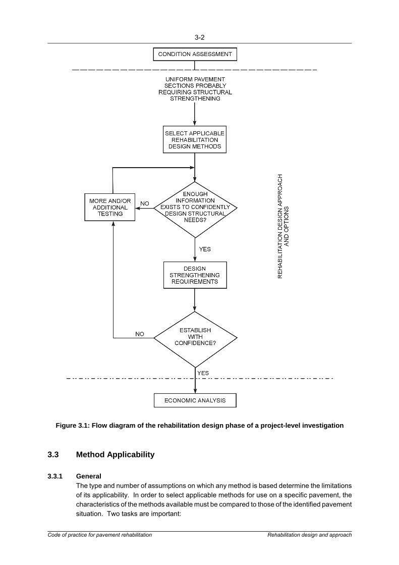
3-2
Code of practice for pavement rehabilitation Rehabilitation design and approach
Figure 3.1: Flow diagram of the rehabilitation design phase of a project-level investigation
3.3 Method Applicability
3.3.1 GeneralThe type and number of assumptions on which any method is based determine the limitationsof its applicability. In order to select applicable methods for use on a specific pavement, thecharacteristics of the methods available must be compared to those of the identified pavementsituation. Two tasks are important:

3-3
Code of practice for pavement rehabilitation Rehabilitation design and approach
� The identification of the prevailing pavement situation that needs to be analysed (asdescribed in Section 2).
� An assessment of a design method in terms of its capability to address critical aspectsthat may be associated with any given pavement situation.
The critical elements of the design and performance variables in a pavement are now identifiedas a first step towards the assessment of the applicability of methods for the analysis of apavement situation. If more than one design method is found to be applicable for use ona specific pavement, the methods should each be used in a multiple analysis approachfor the design of the rehabilitation needs of the pavement.
3.3.2 Design VariablesGeneralDesign variables embody all the structural, load and environmental factors, the interaction ofwhich primarily determine the performance of a pavement. The following elements of thesevariables could have an influence on the ability of a method to analyse any given pavementsituation and should be used to assess the capabilities of rehabilitation design methods.
Structural VariablesMethods should be assessed for limitations with respect to the:
� Type of material in the pavement, and especially the base layers as there is significantdifference in behaviour between different types (bitumen- and cement-treated, granular).
� Thickness of pavement layers. � Strength of pavement layers. � Strength of the pavement as a whole.
Load VariablesMethods should be assessed for limitations with respect to the design traffic loading. This isusually done in terms of the cumulative Equivalent Standard Axle loads (ESAs). Equationsused in methods are derived through the assessment of the behaviour of pavements orpavement materials during loading. These observations cover a range of ESAs, defining therange of traffic loading conditions for which the method is applicable.
Environmental VariablesThe ability of methods to take into account the daily and seasonal variations in climate shouldbe noted. The daily variations in temperature are of importance during the evaluation of thepavement due to their effect on pavement test measurements. Similarly, seasonal variationsin both temperature and moisture could have a marked effect on the bearing capacity of thepavement. Although these factors will not directly influence the applicability of the methods,their omission could adversely affect the results obtained through the use of the methods.
3.3.3 Performance VariablesPerformance variables concern the surface condition and material behaviour elements of apavement. These variables are usually a function of the interaction of the structural, load andenvironmental variables with time.
Pavement condition is described by the visible surface condition of a pavement, which is afunction of any distress present. Rehabilitation design methods base their analysis of thestructure and the design of rehabilitation options on limiting criteria for specific modes of

3-4
Code of practice for pavement rehabilitation Rehabilitation design and approach
distress such as cracking and/or deformation. Critical levels of deformation and/or crackingare directly or indirectly incorporated in most rehabilitation design methods.
The modes of distress (deformation/cracking) are used in pavement rehabilitation designmethods to calculate pavement life. However, deformation and/or cracking can originate in anyof the pavement components, i.e. the surfacing, base, subbase, selected subgrade orsubgrade. The origin of distress and the distress mechanisms are often closely associated withthe material used in the various pavement layers of the structure. For example, in themechanistic design method, the parameters shown in Table 3.1 may be important.
Table 3.1: Critical parameters and properties associated with various material types
Material Type Distress Critical DistressParameters
Thin hot-mix surfacing(20 - 75 mm)
Fatigue crackingHorizontal tensile strain atbottom of the layer (εr)
Thick asphalt basesFatigue cracking Horizontal tensile strain (εr)
Deformation Stress state in asphalt
Granular layers DeformationStress state (σ1, σ2) inmiddle of layer
Cemented layers
Shrinkage cracking Horizontal tensile strain (εr)
Fatigue cracking (slabstate)
Horizontal tensile strain (εr)
Deformation (in theequivalent granular state)
Stress state (σ1, σ2) inmiddle of layer
Subgrade DeformationVertical compressive strain(εv) at top of layer
Rehabilitation design methods are only applicable for use on pavements where the mechanismof distress is similar to that on which the method is based. It follows that rehabilitation designmethods should be assessed in terms of the following performance variables:
� The mode(s) of distress (deformation, cracking) and the respective criteria used todefine a terminal pavement condition.
� The mechanism of distress and the critical distress parameters used in the analysis ofthe mode of distress.
Similar to the design variables, the elements of the performance variables identified aboveshould be used to assess the capabilities of rehabilitation design methods.

3-5
Code of practice for pavement rehabilitation Rehabilitation design and approach
3.4 Pavement Rehabilitation Design Methods
3.4.1 Available ApproachesGeneralPavement rehabilitation design methods may be based on empirical or theoretical principles.In practice, methods often include both theoretical and empirical concepts and can thereforebe associated with assumptions and limitations inherent in these concepts. An understandingof the general characteristics and the influence of assumptions on the prediction of pavementbehaviour is fundamental to the assessment and rating of available methods.
Methods Based on Empirical ConceptsEmpirically-derived methods are based on the results of observations made or experiencegained in trends of behaviour of pavement structures. These observations are usually limitedto specific types of pavement constructed with materials peculiar to certain areas and subjectto specific traffic and environmental conditions. The experience gained under such conditionscannot confidently be applied to different pavements, materials, traffic and environmentalconditions.
Methods based on empirical principles can be divided into methods based on the conditionassessment approach, pavement component analysis approach and response analysisapproach. The main characteristics of these approaches are summarized in Figure 3.2.
a) Condition Assessment ApproachMethods using the condition assessment approach rely on the knowledge andexperience of the assessor to evaluate the condition of the pavement. Decisions aboutthe need for and type of rehabilitation are based on subjective judgment. The assessorapplies personal knowledge of the expected behaviour of the pavement, taking intoaccount the type of pavement, materials, distress, traffic, drainage facilities, geology,topography, vegetation, climate and season within an area as the main input into hisdesign framework. A typical flow diagram of rehabilitation design methods based on thecondition assessment approach is shown in Figure 3.3.
b) Pavement Component Analysis ApproachMethods using the pavement component analysis approach are based on empiricalcorrelations between material tests and expected pavement performance. Thesemethods use laboratory or in situ measurement of an empirically defined materialproperty, such as the California Bearing Ratio (CBR) or Dynamic Cone Penetrometer(DCP) value, to evaluate pavement behaviour. A typical flow diagram of rehabilitationdesign methods based on the component analysis approach is shown in Figure 3.4.

Basis of derivation Empirically derived Theoretically derived
Classification accordingto basic approach
Condition assessment approach Pavement component analysisapproach
Pavement response analysisapproach
Behaviourcharacterisation
Visual inspection usingknowledge and experience
Material tests in the laboratoryand in situ tests
Deflection measurements
Evaluation of pavement Subjective judgement Use empirical relations betweenmaterial tests, traffic loading
and required cover
Use empirical relations betweendeflection measurements and
expected life
Design Decide on requirements usingknowledge and experience
Compare existing pavement tosuitable design obtained from
the empirical relations
Determine overlay thicknessfrom empirically or theoretically
derived relations
Figure 3.2: Main characteristics of the different empirically-derived approaches to rehabilitation design

3-7
Code of practice for pavement rehabilitation Rehabilitation design and approach
Figure 3.3: Empirical rehabilitation design methods based on condition assessment approach

3-8
Code of practice for pavement rehabilitation Rehabilitation design and approach
Figure 3.4: Empirical rehabilitation design methods based on component analysis approach
c) Pavement Response Analysis ApproachMethods using the response analysis approach are based on one or more empirically-derived relationships which are used to predict pavement behaviour. Most of thesemethods use surface deflection as a measurement of pavement response. A typical flowdiagram of rehabilitation design methods based on the response analysis approach isshown in Figure 3.5.

3-9
Code of practice for pavement rehabilitation Rehabilitation design and approach
Figure 3.5: Empirical rehabilitation design methods based on the response analysis approach
Methods Based on Theoretical ConceptsMost of the theoretically-based pavement rehabilitation design methods that have beendeveloped to a stage where practical implementation is possible, have been based on linearelasticity theory. Hence, this document will only discuss methods based on approaches usingthe linear elastic stress-strain theory (also termed "non-hereditary elastic response models").

3-10
Code of practice for pavement rehabilitation Rehabilitation design and approach
A mathematical model usually gives an approximation of actual behaviour. The limitationsassociated with any one model depend on the type of assumptions that form its basis.Therefore, an understanding of the assumptions associated with the linear elastic model wouldalso provide an indication of its limitations.
Rehabilitation design methods incorporating theoretical concepts are based on a number ofapproaches developed to simplify the use of mathematical models. The various methods arecategorised according to the basic approach followed. The approaches usually give a goodindication of the level of sophistication and the general applicability of the methods using theapproach. Approaches identified are:
� Empirical-theoretical approach � Behaviour catalogue approach � Design curves approach � Design charts approach � Non-simplified approach.
The main characteristics of the approaches developed from the linear elasticity theory aresummarized in Figure 3.6.

Basis of derivation Empirically derived Theoretically derived
Non-hereditary elasticresponse
Hereditary visco-elasticresponse
Hereditary plasticresponse
Linear elastic stress-strain
Non-linear elasticstress-strain
Classificationaccording to basicapproach
Empirical/theoreticalapproach
Behaviour catalogueapproach
Design curve approach Design charts approach Non-simplified approach
Behaviourcharacterisation
Use NDT-pavementtest results as input into
empirical/theoreticalrelations
Compare pavementcondition with examples
of pavement state ofbehaviour catalogue
Use pavement testresults in theoretically
derived curves todetermine some
pavement properties
Pavement responsetest results used intheoretically derived
relations and hence incharacterisation charts
Use pavement responsetest results in relations to
determine pavementelastic properties for
computer aided analysis
Evaluation ofpavement
Compare pavementproperties with
empirically deriveddistress criteria
Compare required lifewith identified behaviour
trends in catalogue
Compare one or twopavement failure
parameters (stress;strain) to limiting criteria
Use charts to determineprimary pavement
response parameters(stress; strain) forevaluation against
limiting criteria
Determine pavementresponse parameters
(stress; strain) bycomputer simulation for
comparison againstlimiting criteria
Design Use deflectionreduction curves
(empirically/theoreticallyderived)
Rehabilitationalternatives compared
with behaviourexamples contained in
catalogue
Use design curvesincorporating someoverlay properties
Use thickness designcharts incorporating
various materialproperties
Alternatives determinedby means of computer-
aided calculations
Figure 3.6: Main characteristics of some approaches to pavement rehabilitation design based on linear elastic stress-strain theory

3-12
Code of practice for pavement rehabilitation Rehabilitation design and approach
3.4.2 Rehabilitation Design Methods Used in Southern AfricaGeneralThe selection of methods according to the recommended approach will ensure that anapplicable method is used for the rehabilitation design of each uniform pavement section.Rehabilitation design methods are not discussed in detail in this document, but the maincharacteristics of some of these are summarized in Appendix B. The recommended methodsare the:
� Asphalt Institute method9
� DCP method8
� TRL deflection method6, � Shell overlay design method11
� South African mechanistic design method12.
Various methods, including those discussed in Appendix B have been assessed13,14 boththeoretically and practically for a limited number of pavements in southern Africa. Based onthis assessment some recommendations are made with regard to the use of rehabilitationdesign methods in southern Africa.
Empirically-derived MethodsSome of the abovementioned methods are based on the same approach (refer to Appendix B)and the recommendations regarding the further development and use of these methodsconcern more than one method. Hence, these methods are discussed under the heading ofthe basic approach by which they are classified.
The design curves of the empirically-derived methods considered are based on deformationonly and contain many other limitations (refer to Appendix B). Hence, it is recommended thatthe use of these methods be limited to low category pavements with low traffic volumes.Results obtained through the use of these methods on other pavements should be verifiedthrough the use of a theoretically-based method.
a) Response Analysis ApproachThe Asphalt Institute and the TRL deflection methods are based on the responseanalysis approach. Deflection-based methods have severe limitations for the analysisof pavements containing semi-rigid cemented layers. Hence these methods are notrecommended for the analysis of pavements containing cement-treated layers.
i. Predicting Remaining LifeIt is important to take the type of pavement into account and hence the designcurves of the TRL deflection method are recommended to determine theremaining life of the pavement. These curves should be used with the deflectionmeasurements processed as recommended in Appendix B, taking into accountthe various pavement categories.
It has been shown7,14 that results obtained through the use of the TRL curves areadversely affected by the use of the temperature adjustment figures (microclimate), as recommended in the TRL deflection method. Similar trends werefound with the use of the temperature adjustment figure recommended for use bythe Asphalt Institute method.
3-13
Code of practice for pavement rehabilitation Rehabilitation design and approach
Hence, it is recommended that the curves for the prediction of remaining life beused without the adjustments of deflection measurements to allow for the effectof temperature, until such required adjustments have been studied in more detailunder southern African conditions.
Currently specific information on the adjustment of deflections to take into accountseasonal variations (macro-climate) are not available for southern Africa. It isrecommended that such adjustments be incorporated in the method based on theresponse analysis approach, after a study to determine their effect has beenundertaken in southern Africa.
ii. Rehabilitation DesignThe methods based on deflection measurements use overlay design curves todetermine the rehabilitation needs of pavements. The cause and mechanism ofdistress are important when deciding on the rehabilitation needs. Hence the useof overlay design curves should be limited to pavements where the cause andmechanism of distress is associated with the subgrade.
b) Pavement component analysis approachThe Asphalt Institute and the DCP methods are based on pavement component analysisapproach.
i. DCP MeasurementsThe DCP measuring device cannot be used on pavements with stronglycemented layers. However, limited studies have shown that the DCP method cansuccessfully be used on pavements containing thick bituminous treated layers.
The DCP method, as analysed in Appendix B, is recommended for use onbalanced or nearly-balanced pavements containing bituminous treated, lightlycemented (UCS < 3 MPa) and granular layers. The effect of seasonal changescould be incorporated to improve the accuracy of long term predictions.
ii. Analysis of Pavement LayersThe Asphalt Institute method (refer to Appendix B) has been shown to givereasonably accurate predictions of remaining life, but should not be used todetermine rehabilitation requirements. It is recommended that this procedure beused for the prediction of remaining life only, and that the results be compared toDCP and/or deflection based methods.
Theoretically-derived MethodsMethods developed overseas are usually based on distress criteria which are not generallyapplicable for use in southern Africa7,14, so it follows that methods and procedures which werenot developed in southern Africa should not be used before these have been verified underlocal conditions.
Furthermore, the assumptions incorporated in the methods based on the empirical/theoreticalapproach, the design curves approach and the design charts approach, make these methodsunreliable for the analysis of complicated problems. Hence, it is recommended that methodsbased on these approaches should not be used for the analysis of pavements.

3-14
1 The South African Department of Transport through its research programme in the Directorate:Transport Economic Analysis, has commissioned the completion of three documents for therehabilitation design of pavements for use in Southern Africa. These are:Department of Transport Research Report 91/243: "Pavement Rehabilitation Design Based onMaximum Surface Deflection Measurements",Department of Transport Research Report 91/241: "Pavement Rehabilitation Design Based onPavement Layer Component Tests (CBR and DCP)", andDepartment of Transport Research Report 91/242: "The South African Mechanistic PavementRehabilitation Design Method".
Code of practice for pavement rehabilitation Rehabilitation design and approach
The only theoretically-based methods that can, with confidence, be recommended for thedetailed analysis of pavements are those based on the non-simplified approach. The SouthAfrican mechanistic design method is based on the non-simplified approach and isrecommended for use.
3.4.3 RecommendationsThree methods for pavement rehabilitation design are recommended for use in southern Africa.These are a deflection method, DCP method and the South African mechanistic designmethod. These methods are assessed in terms of their limitations and abilities with regard tothe various design and performance variables in Figures 3.7 and 3.8 respectively.
In order to assist in the selection of an appropriate rehabilitation design method, the use of therecommended three methods in terms of the main design variables are shown in Figure 3.9.Note that Figure 3.9 should be used together with Figures 3.7 and 3.8 before a final selectionof an applicable method is made (see Footnote1).

Limitations in structural variables Accumulated traffic loadClimate (incorporate
functions for)
Rehabilitationdesign method
Type of pavement Thickness Componentstrength
Composite strength Equivalent Standard Axleload (ESAs)
Micro-climate
Macro-climate
Deflection method Cemented base n/a n/a n/a Remaining life:0.4 - 10 million ESAs
Overlay design:0.2 - 20 million ESAs
No NoBituminous base - - Defl > 0.4 AND < 1.3 mm
Lightly cemented base - - Defl > 0.4 AND < 1.4 mm
Granular base - - Defl > 0.5 AND < 1.5 mm
DCP Method Cemented base n/a n/a n/a
0.2 - 10 million ESAs No PartialBituminous base -
Lightly cemented base - UCS < 3 MPa 200 � DSN800 � 750
Granular base - - 70 � DSN800 � 420
South Africanmechanisticmethod
Cemented base - - -
0.01 - 100 million ESAs No PartialBituminous base - - -
Lightly cemented base - - -
Granular base - - -
n/a Method not applicable for the analysis of pavement type? Uncertainty- No restrictions
Figure 3.7: Applicability of rehabilitation design methods in relation to the main design variables in a pavement situation13,14

Crit
ical
dis
tress
par
amet
er
Mat
eria
l ty
pe
Pave
men
t co
mpo
nent
Mod
e o
f dis
tress
Orig
in,
caus
e an
d m
echa
nism
of
dist
ress
take
n in
to a
ccou
nt in
des
ign
of o
ptio
ns?
Mode of distress andcriteria used to
define the pavementfailure condition
DEFORMATION CRACKING
Surface Pavement layersSSG +
subgradeCompositestructure Surface Pavement layers
Bituminous BituminousGranular or
equivalent granular Granular - Bituminous Bituminous Cemented
Rehabdesignmethod
Deformation(rutting) Cracking
Stability stressstate
Stabilitystress state
Stressstate
(σ1 σ2)
Verticalstrain
(εv)
Verticalstrain(εv)
Stress andor strain in
layers
Hor. Strain (εr) Hor. Strain (εr) Hor. Strain (εr)
Bottomlayer
In layer Bottomlayer
In layer Bottomlayer
In layer
Deflectionmethod 20 mm X X X X X � � No
DCPmethod 20 mm X ? ? � X X � Yes
SouthAfricanmechanisticmethod
8 mm or12 mm or
18 mm� X X � � � X �
�
Withrecom
�
�
Withrecom
�
�
Withrecom
Yes
Method not applicable for the analysis of the mode of distress? Uncertainty� Takes into accountX Does not take into account
Figure 3.8: Applicability of rehabilitation design methods in relation to the main performance variables in a pavement situation13,14
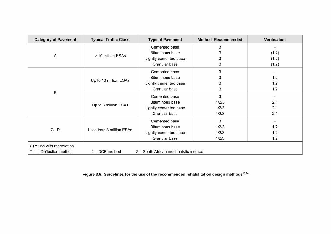
Category of Pavement Typical Traffic Class Type of Pavement Method* Recommended Verification
A > 10 million ESAs
Cemented baseBituminous base
Lightly cemented baseGranular base
3333
-(1/2)(1/2)(1/2)
B
Up to 10 million ESAs
Cemented baseBituminous base
Lightly cemented baseGranular base
3333
-1/21/21/2
Up to 3 million ESAs
Cemented baseBituminous base
Lightly cemented baseGranular base
31/2/31/2/31/2/3
-2/12/12/1
C; D Less than 3 million ESAs
Cemented baseBituminous base
Lightly cemented baseGranular base
31/2/31/2/31/2/3
-1/21/21/2
( ) = use with reservation* 1 = Deflection method 2 = DCP method 3 = South African mechanistic method
Figure 3.9: Guidelines for the use of the recommended rehabilitation design methods13,14

4-1
Code of practice for pavement rehabilitation Practical and functional aspects
4. PRACTICAL AND FUNCTIONAL ASPECTS
4.1 Introduction
The practical and functional aspects discussed here include the applicability, constructability,performance (structural and functional) and maintainability of methods, materials andprocedures. These aspects differ considerably from project to project and the designerrequires detailed knowledge of each project and experience in pavement rehabilitation designin general to effectively take these into account.
This section covers some of the more common practical and functional aspects that should beconsidered in pavement rehabilitation design. The omission of these aspects could easilyresult in an otherwise technical sound design being unsuccessful. Practical and functionalaspects influencing rehabilitation design should not be seen in isolation and this section shouldbe considered together with the rest of the document.
4.2 Applicability
4.2.1 GeneralMany procedures, methods and other aspects may not be applicable to specific projectconditions, and the applicability should be determined before undertaking rehabilitation design.In this discussion, "applicability" could refer to the use of methods of investigation and design,material selection, modification and application, and most important, the practicality of availablerehabilitation options.
4.2.2 Methods of Investigation and DesignMethods of investigation and design and their applicability to specific projects are discussedin detail in Sections 2 and 3. These sections and accompanying references should be studiedto ensure that applicable tests and methods are being used on a particular project.
4.2.3 MaterialsThe availability of materials has been identified in Section 1 as a logistical input which couldinfluence pavement rehabilitation design. The available materials influence rehabilitationdesign in that they may only be suitable for use in particular pavement layer types. Thecharacteristics of the materials may be such that strengthening or modification may berequired, or in some cases the available materials may not be suitable for modification orstrengthening. Hence the rehabilitation design should ensure that the available materials canbe used as specified.
4.2.4 Rehabilitation OptionsSeveral rehabilitation options or strategies could normally be used to rectify a distressedpavement. However, it is often found that some options are more suitable than others, and thedesigner could save considerable effort and time by concentrating on these options. Thesuitability of rehabilitation options is often a function of the characteristics of the pavement,such as the cause and mechanism of distress and the pavement situation. For example, ifpavement deformation has been identified as originating in the asphalt surfacing of apavement, it could be more applicable to replace the existing surfacing with adeformation-resistant surfacing than to cover the deformed layer with another asphalt layer.

4-2
Code of practice for pavement rehabilitation Practical and functional aspects
4.3 Constructability
4.3.1 GeneralAlthough many designs may be applicable, or certain alterations desirable, the actualconstruction thereof could present major obstacles. These could include aspects such as theaccommodation of traffic during rehabilitation, the widening of the current paved surface, theavailability of equipment and the influence of the rehabilitation action on the environment.
4.3.2 Accommodation of TrafficThe accommodation of traffic has been identified as a logistical input into rehabilitation designin Section 1, which is influenced by the type of terrain and area in which the road is to beconstructed. Traffic accommodation could be the decisive factor in the selection of a specificrehabilitation option and requires consideration from the outset of a project as it could accountfor ten to twenty per cent of the total costs of the project.
4.3.3 Widening of the Paved SurfaceSome sub-standard roads may technically require widening of the paved surface. However,where little extra width may be required the constructability and compatibility with the existingpavement should be kept in mind. Because of confined space, it could be difficult to work totight specifications, making widening very expensive and hence not cost-effective. Wherewidening is essential, the improvement of existing pavement layers or the additional surfacingof the shoulders at little extra cost should be investigated. Widening should be planned so thatthe joint does not coincide with one of the wheeltracks.
Widening of the road should also take into account the drainage capacity of the existing andnew pavement layers. If the additional width is not compatible with the existing pavement itcould result in the trapping of water and hence, early failure.
4.3.4 Layer Thickness ConstraintsExisting surface irregularities, geometry and existing layer thicknesses should be taken intoconsideration in the final design of layer thicknesses. It is considered essential to take crosssections of the existing road before final design documents are prepared to ensure that therequired rehabilitation needs are met, allowing for existing irregularities.
4.3.5 Availability of ResourcesIn practice, rehabilitation investigations and design should take into account the availability ofspecialized equipment. This aspect has been discussed under logistical inputs to rehabilitationdesign in Section 1 of this document.
4.3.6 Environmental InfluenceThe rehabilitation of a pavement could cause considerable environmental pollution which couldplay an important role in the selection of a rehabilitation option. For example, dust pollution(granular materials) or smoke pollution (hot-mix recycling) could exclude some options for usein built-up or sensitive areas. On the other hand, the creation of large quantities of wastematerial is often not desirable, prompting the investigation of options which allow for the re-useof materials.

4-3
Code of practice for pavement rehabilitation Practical and functional aspects
4.4 Performance Adequacy
4.4.1 GeneralThe performance of the rehabilitated pavement is often associated with only the structuraladequacy of the design. These structural aspects are fully covered by the approach torehabilitation design in Sections 2 and 3 in this document. However, both the structural andfunctional performance of the pavement are influenced by additional aspects such as theadequacy of drainage facilities and the type of surfacing or wearing course. These aspectsshould also be taken into consideration during the design of rehabilitation options.
4.4.2 DrainageGeneralPavement distress can often be related to the lack of drainage facilities, their ineffectivenessor inadequacy. A detailed survey of the adequacy and performance of the existing drainagefacilities and recommendations for their improvement where required, are considered anessential part of a rehabilitation investigation. Drainage improvements should receive thehighest priority, and should include surface drainage, side drains, subsurface drainage andcross drainage.
Surface DrainageThe rehabilitated pavement surface should allow for the free flow of rain water from the pavedsurface through the provision of an adequate side slope.
Side DrainsBlocked and overgrown side drains are ineffective, often resulting in the ponding of water.Concrete side-drains should be considered in cases of erosion or obvious blockage or incuttings. The placement and influence of concrete side drains on safety, maintenance andfuture pavement rehabilitation should be taken into account in their design.
Sub-surface DrainageSub-surface drains are relatively expensive and, if required, should be thoroughly investigatedand motivated. These would usually be appropriate in cuttings where localized pavementfailures have occurred.
Cross DrainageAdditional cross drains should only be considered in cases where regular flooding of the roadoccurs. It is important to improve existing ineffective cross-drains to ensure that they willfunction properly in the future.
4.4.3 Surfacing and Wearing Course SelectionSeveral functional and practical aspects should be considered in the selection and design ofthe surfacing or wearing course. The design of asphalt surfacings is covered in detail inTRH815, where aspects such as deformation and fatigue characteristics are discussed.Similarly, surface treatments and the design thereof are covered in detail in TRH310. Thesedocuments therefore provide good insight into the selection and design of the surfacing orwearing course where local guidance is unavailable.
In addition to the structural qualities of the surfacing or wearing course, functional aspects suchas riding quality, skid resistance, traffic noise and even optical (i.e. light reflections) propertiesshould be considered.

4-4
Code of practice for pavement rehabilitation Practical and functional aspects
4.5 Maintainability
Pavements tend to have a long lifespan which could include several maintenance andrehabilitation cycles. Hence, in the selection of the type of rehabilitation of a pavement, thefuture maintenance or even rehabilitation of the pavement should be considered. It is clearlyunwise to invest in an asset (pavement) if the future availability or quality of maintenance is atrisk.
With the possible use of innovative, modified or new materials especially, the availability ofmaterial, equipment, expertise and funds for the maintenance of the pavement in the futureneed to be considered.

5-1
Code of practice for pavement rehabilitation Economic analysis
5. ECONOMIC ANALYSIS
5.1 Introduction
Economic analysis is an aid in the decision-taking process, providing an important basis forsound and objective decision-taking. Economic analysis determines the cost-benefit ratio andthe Economic Internal Rate of Return (EIRR) of a project to justify its commission relative tocompeting capital projects. It is usually done prior to the awarding of contracts for project-levelrehabilitation investigations as part of the prioritisation of rehabilitation projects, and is normallyobligatory when funding from donor agencies is sought.
This type of detailed analysis should be undertaken by an experienced economist, and isoutside the scope of this document, although the underlying principles are outlined here.
In the case of comparing rehabilitation options for the same project, it is not usually necessaryto undertake a full analysis leading to an EIRR value. Rather, the objective of the economicanalysis as part of a project-level rehabilitation investigation procedure is to determine the mosteconomical of the appropriate remedial options.
This is a more simplified process, since a number of the parameters are the same in eachcase, and the basis for comparison is total Present Worth of Costs (PWOC). These are madeup from agency costs and road user costs:
i. Agency Costs: � Initial rehabilitation costs (including costs for traffic accommodation) � Maintenance costs during the analysis period (including administration costs) � Future capital costs (e.g. stage remedial action). � Salvage value at the end of the analysis period.
ii. Road User Costs: � Delay costs due to rehabilitation activities. � Vehicle operating costs. � Accident costs. � Time costs.
The various rehabilitation options are compared by calculating the total present worth of thecosts (PWOC) of the various items listed above for each option. Ideally, this comparisonshould incorporate for each option the probability of different outcomes and resultant actionsduring the analysis period to obtain the most probable cost of each option. This can befacilitated by the use of decision trees and Bayesian analysis, and this approach isdemonstrated in Appendix D.
The recommended procedure for the economic analysis of rehabilitation options for a specificproject is outlined in Figure 5.1.

5-2
Code of practice for pavement rehabilitation Economic analysis
Figure 5.1: Economic analysis as part of project level pavement rehabilitation design

5-3
Code of practice for pavement rehabilitation Economic analysis
5.2 Agency costs
5.2.1 Rehabilitation costsThis cost item is the initial cost of the rehabilitation of the section of road for the option underinvestigation, and should reflect the probable contract cost if the project is to be let. Currentunit costs, which should include all relevant capital cost items associated with the rehabilitationconstruction (such as the costs of traffic accommodation), must be used in the calculations.
5.2.2 Maintenance CostsMaintenance costs expected during the design period should be included in the economicanalysis. These will include costs involved in the regular inspection of the pavement,administration costs and repair costs due to natural ageing and weathering of the pavement,e.g. restoring the skid resistance and the sealing of cracks.
Many of these costs are difficult to assess since rehabilitation options often react differently withtime, due to the susceptibility of certain materials to ageing, cracking or weathering. Therefore,the economic analysis should provide for the likelihood that these additional costs will occur.These costs are included as current unit costs.
Table 2.10 gives an indication of the expected life of pavement surfacings under normalconditions, after which maintenance is usually required, and this can be used where localinformation is unavailable to determine periodic maintenance costs (resealing/resurfacing).
5.2.3 Future Capital CostsThis cost item includes all major capital costs foreseen during the rehabilitation design periodas a result of the adoption of a specific rehabilitation option. These costs occur when, formonetary or political reasons, a holding action and future interim rehabilitation actions areconsidered, or when stage rehabilitation construction is considered. Current unit costs areused.
This cost item also includes the cost of major rehabilitation because of distress or lack ofmaintenance. Provision should be made for interim rehabilitation, taking into account thecategory of road, the policy of the road authority and the rehabilitated pavement structure.
5.2.4 Residual Value (Salvage Value)The value of the pavement at the end of the analysis period is dependent on various factors,including the:
� Anticipated uses of the material or pavement at the end of the analysis period, such as: - Recycling of the material. - Removing and selling of the material. - Rehabilitation of the pavement and hence re-use of the material as a foundation
for a new road. - Abandoning of the road with or without restoring the original vegetation. - Combinations of the above.
� Volume, type, age and expected life of the material. � Market value of the pavement or material at the end of the analysis period.

5-4
Code of practice for pavement rehabilitation Economic analysis
Salvage value � 1 �AB
Cost of new overlay
The salvage value is often difficult to assess due to the various unknown factors. However,due to the length of the analysis period and the discount rate, small differences in salvagevalue estimates usually have little influence on the final result.
The obvious method for calculating the salvage value is to determine the value of the materialat the end of the analysis period. This may be the difference between the costs of new materialand costs of using the existing material on the road. For example, the salvage value of asphaltoverlay can be determined by using a straight line depreciation (Equation 7), where:
...Equation 7
withA = age of the overlayB = expected life of the overlay.
However, the above method can be misleading if it is expected that the road will have to berehabilitated again at the end of the analysis period. The fact that the road has already beenestablished and is carrying traffic is worth a considerable amount and this could be a majorcontribution to the salvage value of a road. In these cases the difference between the cost ofconstructing a new road and the cost of rehabilitating and/or upgrading the existing road wouldbest represent the salvage value of the pavement.
5.3 Road User Costs
5.3.1 GeneralRoad user costs, when taken over the design period, will usually far exceed the agency costs.They are, however, difficult to determine with any level of confidence and hence detailedeconomic analyses require specialist economist input. In the case of comparing rehabilitationoptions for the same road, however, certain conditions are the same which simplifies thecalculation.
In certain cases, differences in road user costs between different options for the same projectwill, in effect, be minimal and may be disregarded in a comparative study if taken over thesame analysis period under the same traffic conditions.
However, road user costs cannot be disregarded completely in comparative studies sincealternative remedial options may require different construction techniques and differentconstruction periods. This will result in differences in the disruption of traffic during the actualrehabilitation of the pavement and, hence, differences in the delay costs and accident costs tothe road user.
Under heavy traffic conditions these costs may contribute significantly to the total cost of someremedial options and should be taken into account. In these studies, vehicle operating costsand time costs are only of importance when calculated as part of the delay costs incurredduring the actual rehabilitation of the road.

5-5
Code of practice for pavement rehabilitation Economic analysis
5.3.2 Delay Costs Due to Rehabilitation ActivitiesGeneralThis cost item can be significant, especially when a heavily trafficked road such as an inter-urban freeway is rehabilitated. Only the differences between the costs of the various optionsneed to be considered.
If all the available options disrupt the flow of traffic for the same period of time and to the sameextent, this cost item will be the same for all the alternatives and may therefore be disregarded.However comparing, for example, an overlay and reconstruction, differences in both the degreeof disruption and the rehabilitation construction time will occur. In this case, delay costs mayprove to be the decisive factor in selecting a rehabilitation option.
Delay costs, as a result of longer time spent on the road, the slower speeds and the morecongested traffic conditions, include time costs, vehicle operating costs and accident costs.The cumulative effect of all these contributory items should be included in a thorough study.
Vehicle Operating Costs (VOC)Vehicle operating costs comprise the following components:
� Vehicle capital cost � Vehicle maintenance cost � Fuel costs � Oil costs � Tyre costs
Some of the components of vehicle operating costs, such as depreciation costs, are notapplicable when delay costs due to rehabilitation activities are calculated. Each componenttherefore requires careful consideration and should not be blindly incorporated into anyanalysis.
Many road departments try to monitor VOC in order that full economic analyses can beundertaken on different projects but, as indicated above, the application and interpretation willnormally be undertaken by an experienced economist. In such cases, differences in terrainand in deterioration of different roads, lead to significant differences in VOC.
Fortunately this cost item can usually be disregarded in the comparative economic analysis ofrehabilitation works for a particular road because it is usually the same for the different options.This is because the various options tend to meet similar design requirements, e.g. the provisionof an acceptable service on the same route over the same design period.
Time CostsThis cost item should reflect the economic cost of time spent by road users on the differentrehabilitation options. For practical purposes in comparing rehabilitation options on the sameroad section, it can be reduced to the differences in time lost due to delays caused byrehabilitation activities (the cost to the economy). It is, however, by far the most difficult toassess, and even the most experienced economists tend to simplify (reduce) the time costcomponent in full economic analyses.
The reason for this is that the estimate, which must answer the question "How much economic(productive) time is lost due to the rehabilitation works compared with before and what is itsvalue?", is comprised solely of vagaries, some of which include:

5-6
Code of practice for pavement rehabilitation Economic analysis
PWOC � P � �n
i � 1Ai ( 1 � r )�i
� Sn ( 1 � r )�n
Term 1 Term 2 Term 3
� Apart from estimating the additional time spent by the road users due to delays at thesite, there will generally be some knock-on or ripple effect due to, for example, roadusers seeking alternative routes causing delays on other roads, delayed deliveriesholding up production, etc.
� How is the total additional time converted into economic (productive) time? Not alladditional time (time "wasted") can be considered productive, but how can the balancebe determined? Does everyone affected work?
� What should be the unit cost associated with the time value? Should it be based onnational per capita income? Is the sample biassed because it does not reflect the overallsocio- and demographic makeup of the country?
and so on. For comparative purposes, the time costs should be ignored.
5.3.3 Accident Costs Due to Rehabilitation ActivitiesThis cost item is determined by using accident frequency and accident unit costs statistics toestimate a cost attributable to the rehabilitation work. Taken over the rehabilitation designperiod, these costs may be equal for the various rehabilitation options and, in such cases, canbe disregarded (assuming that all options will ensure that a minimum level of service ismaintained during the rehabilitation design period).
However, during the rehabilitation construction period, different options may cause differencesin traffic congestion, and therefore notional differences in the number of accidents and hencein accident costs.
In such cases some estimate of the costs and, in particular, the cost differences should bemade.
5.4 Principles of the Economic Analysis
5.4.1 Present Worth of Costs (PWOC)The different cost items discussed in the preceding sections need to be meaningfully combinedinto a single comparative value for each rehabilitation option. The present worth of cost(PWOC) method is commonly used for this purpose.
In this method all future costs are discounted to the present worth of costs (ie, to the worth intoday's currency value) by using an acceptable discount rate. The rehabilitation option whichproduces the lowest expected PWOC should be selected as the most economic rehabilitationoption.
The present worth of costs can be calculated from the following formula (Equation 8):
...Equation 8
with: PWOC = Present worth of costs
Where P = Initial rehabilitation costs

5-7
Code of practice for pavement rehabilitation Economic analysis
Ai = Relevant costs occurring during the analysis period after iyears
Sn = Salvage value at the end of the analysis period n years latern = Analysis periodr = Discount rate
The equation consists of three basic parts:
Term 1 - the initial cost (including the construction cost and any other costsassociated with the construction work as derived from the road user costs)
Term 2 - summation of all periodic costs arising during the life of the road (in theanalysis period), such as reseals, or additional work for a stage-construction, discounted to today's values.
Term 3 - the salvage value of the road at the end of the analysis period, subtractedfrom the cost assessment as it represents a benefit to the road agency.
As noted previously in Section 5.2.4, the estimation of salvage value can be difficult and, infact, inappropriate if the road will be in different conditions at the end of the analysis period fordifferent options.
Since the objective of the economic analysis as part of the rehabilitation procedure is todetermine the most economical rehabilitation option, the salvage value is most convenientlyincluded in the analysis by considering the difference in costs at the end of the analysisperiod, to bring all the options to the same end condition. In such a comparison, the coststo bring all the options to the same end condition at the end of the analysis period are addedrather than subtracted as Term 3.
5.4.2 Specific AspectsAnalysis PeriodThe analysis period is the period over which the different remedial options are compared andduring which all relevant cost items are taken into account. Usually this period is taken to bethe same as the rehabilitation design period. When the PWOC method is used for theeconomic analysis, the analysis period must be the same for all the alternative options withina specific rehabilitation study.
InflationWhen all cost items escalate at the same rate, inflation is taken into account by calculating allfuture expenditures at current unit costs. The real discount rate is then used to determine thePWOC of these future costs.
However, the cost of some materials may escalate at much higher or lower rates that theaverage inflation rate. These differences can be taken into account by applying the approachadopted in the following example.

5-8
Code of practice for pavement rehabilitation Economic analysis
ExampleAssume that the price of asphalt will escalate at an annual rate of 15 per cent for the next10 years, whereas the average rate of inflation is expected to be 10 per cent per annumover the same period.
The PWOC of a 50 mm asphalt overlay placed in 10 years' time is now calculated asfollows, assuming a current discount rate of 8 per cent (use the figure appropriate for thecountry, normally readily available through national statistical data):
Current cost (1997) of one km of 50 mm asphalt overlay = CU* 50 000 (say)
* CU = currency unit
� Project today's cost at the expected price escalation rate (15 per cent per year)� the expected 2007 cost of one km of 50 mm asphalt overlay in 2007 money
= CU 50 000 (1+0,15)10 =CU 202 278
� bring this cost back to today's prices by removing the inflation effect (10 per centper year)The 2007 cost of a 50 mm asphalt overlay in 1997 money
= CU 202 278 (1+0,10)-10** = CU 77 987** NB Note the negative sign as this is effectively going back in time
This now gives today's effective cost for the asphalt overlay laid in 2007 (significantlymore than today's cost, due to the real price escalation effect, more than inflation).
The PWOC (1997) of one km of 50 mm asphalt overlay placed in 2007 is then calculatedusing the effective cost of placement in today's prices, and the current discount rate:
= CU 77 987 (1+0,08)-10 = CU 36 123
Discount RateThe use of the present worth of cost method requires the selection of a suitable discount rate.This rate is dependent on various factors, including the:
� Effective rate of borrowing money. � Rate of return that money can earn if invested.
Discount rates are determined by national financial agencies, based on the various factors, andthe appropriate one should be used in PWOC calculations. Typical values lie between threeand 10 per cent.
5.5 Incorporating Uncertainty
The discussion on the various cost items highlighted the general uncertainty inherent in anyprojection of future circumstances. In order to accommodate this, it is recommended thatBayesian analysis and decision trees are used in the PWOC analysis to appraise some of theuncertainties. The principles are outlined in Appendix C.

5-9
Code of practice for pavement rehabilitation Economic analysis
Decision trees and the Bayesian theory are ideally suited to assess various probable outcomeswithin the PWOC method. This system further provides for the incorporation of personalexperience of conditions and materials in a formal analysis procedure. The application of theseprocedures for the economic analysis of applicable rehabilitation options is demonstrated inAppendix D.
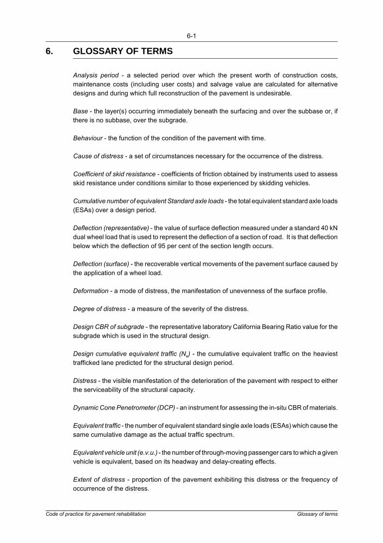
6-1
Code of practice for pavement rehabilitation Glossary of terms
6. GLOSSARY OF TERMS
Analysis period - a selected period over which the present worth of construction costs,maintenance costs (including user costs) and salvage value are calculated for alternativedesigns and during which full reconstruction of the pavement is undesirable.
Base - the layer(s) occurring immediately beneath the surfacing and over the subbase or, ifthere is no subbase, over the subgrade.
Behaviour - the function of the condition of the pavement with time.
Cause of distress - a set of circumstances necessary for the occurrence of the distress.
Coefficient of skid resistance - coefficients of friction obtained by instruments used to assessskid resistance under conditions similar to those experienced by skidding vehicles.
Cumulative number of equivalent Standard axle loads - the total equivalent standard axle loads(ESAs) over a design period.
Deflection (representative) - the value of surface deflection measured under a standard 40 kNdual wheel load that is used to represent the deflection of a section of road. It is that deflectionbelow which the deflection of 95 per cent of the section length occurs.
Deflection (surface) - the recoverable vertical movements of the pavement surface caused bythe application of a wheel load.
Deformation - a mode of distress, the manifestation of unevenness of the surface profile.
Degree of distress - a measure of the severity of the distress.
Design CBR of subgrade - the representative laboratory California Bearing Ratio value for thesubgrade which is used in the structural design.
Design cumulative equivalent traffic (Ne) - the cumulative equivalent traffic on the heaviesttrafficked lane predicted for the structural design period.
Distress - the visible manifestation of the deterioration of the pavement with respect to eitherthe serviceability of the structural capacity.
Dynamic Cone Penetrometer (DCP) - an instrument for assessing the in-situ CBR of materials.
Equivalent traffic - the number of equivalent standard single axle loads (ESAs) which cause thesame cumulative damage as the actual traffic spectrum.
Equivalent vehicle unit (e.v.u.) - the number of through-moving passenger cars to which a givenvehicle is equivalent, based on its headway and delay-creating effects.
Extent of distress - proportion of the pavement exhibiting this distress or the frequency ofoccurrence of the distress.

6-2
Code of practice for pavement rehabilitation Glossary of terms
Fill - subgrade material placed over the roadbed.
Geometric design - the design of the geometry of the road surface for traffic flow and for thesafety and convenience of the road user.
Heavy vehicle - a vehicle with an axle load > 4 000 kg, usually with dual rear wheels.
Heavy Vehicle Simulator (HVS) - a machine for the accelerated simulation of traffic loads ona section of pavement.
Initial equivalent traffic - the average daily equivalent traffic predicted for the first year of thestructural design period.
Inter-urban road - a primary road between urban areas carrying from light to heavy traffic witha high level of service.
Length of distress - a measure of the extent of distress.
Lacroix Deflectograph - a machine for the measurement of deflection on the surface of apavement under a standard 40 kN dual wheel load.
Maintenance - a remedial measure to improve the serviceability (not usually the geometricproperties) or the structural capacity of a road.
Maintenance priorities - the selection of certain maintenance tasks deemed to be of greatereconomic value than others.
Material depth - the depth defining the pavement and the minimum depth within which thematerial CBR should be at least 3 percent at in situ density.
Material properties - the reaction of various road building materials to changes in stress undervarying conditions of moisture and density.
Maximum annual deflection - the deflection measured under a standard 40 kN dual wheel loadadjusted for seasonal variations to represent the maximum measurable deflection during aone-year period on a section of road.
Mechanistic analysis - analysis of a system taking into account the interaction of variousstructural components as a mechanism, here used to describe a design procedure based onfundamental theories of structural and material behaviour in pavements.
Mechanism of distress - the physical process by which the cause of the distress results in thedistress.
Modes of distress - the six major classes of distress.
Modified material - a material the physical properties of which have been improved by theaddition of a stabilising agent but in which cementation has not occurred.
Multi-depth Deflectometer (MDD) - instrument for the measurement of in-situ deflections atvarious depths in a pavement.
6-3
Code of practice for pavement rehabilitation Glossary of terms
Pavement behaviour - the function of the condition of the pavement with time.
Pavement description - description of the condition of a road in terms of its ability to fulfill itsfunctional requirements.
Pavement evaluation - the assessment of the degree to which the road fulfils its functionalrequirements.
Pavement layers - the combination of material layers constructed over the subgrade in orderto provide an acceptable facility on which to operate vehicles.
Pavement situation - incorporates all the design (structural, traffic and environmental) variablesand performance (surface and material) variables that could influence pavement behaviour.
PCA Roadmeter - instrument for assessing riding quality, developed by the Portland CementAssociation.
Performance - the measure of satisfaction given by the pavement to the road user over aperiod of time, quantified by a serviceability/age function.
Position of distress - the situation of distress with respect to the surface of the road.
Present worth of costs - sum of the costs of the initial construction of the pavement, the latermaintenance costs and the salvage value discounted to a present monetary value.
PSI - Present Serviceability Index, a measure of riding quality obtained by the use ofinstruments.
Pumping - the mechanism causing water to move soil fines from within the pavement upthrough the surface of the pavement. Also used as a description of the appearance of thepavement as a result of the mechanism working.
Reflection cracks - cracks in asphalt overlays or surface treatments that reflect the crackpattern of the pavement structure underneath.
Rehabilitation design period - the chosen minimum period for which a pavement rehabilitationis designed to carry the traffic in the prevailing environment, with a reasonable degree ofconfidence, without necessitating further pavement rehabilitation.
Riding quality - the general extent to which road users experience a ride that is smooth andcomfortable or bumpy and thus unpleasant and perhaps dangerous.
Roadbed - the in situ material below selected layers and fill.
Rural road - a surfaced secondary road serving small rural communities and carrying very lighttraffic with a relatively low level of service.
SCRIM - instrument for the assessment of skid resistance.
Selected layer - the lowest of the pavement layers, comprising controlled material, either in situor imported.

6-4
Code of practice for pavement rehabilitation Glossary of terms
Serviceability - the measure of satisfaction given by the pavement to the road user at a certaintime, quantified by factors such as riding quality and rut depth.
Skid resistance - the general ability of a particular road surface to prevent skidding of vehicles.
Slab - the pavement layer of concrete which is placed over a prepared subbase and acts asbase and surfacing combined.
Smoothing of surface texture - mode of distress, loss of macro-texture and/or micro-texture.
Standard Axle (SA) - (80 kN/8,160kg/18,000lb/18kip) single axle dual wheel configuration.
Structural capacity - the ability of the pavement to withstand the effects of climate and traffic.
Structural description - a list of values of properties of the pavement relevant to a mechanisticevaluation.
Structural design - the design of the pavement layers for adequate structural strength underthe design conditions of traffic loading, environment and subgrade support.
Structural design period - the chosen minimum period during which the pavement is designedto carry the traffic in the prevailing environment with a reasonable degree of confidence thatstructural maintenance will not be required.
Structural distress - distress pertaining to the load-bearing capacity of the pavement.
Structural evaluation - the assessment of the structural capacity of a pavement.
Structural maintenance - measures that will strengthen, correct a structural flaw in, or improvethe riding quality of an existing pavement, e.g. overlay, smoothing course and surfacetreatment, partial reconstruction (say base and surfacing), etc.
Structural response - the stresses and strains introduced in to the pavement by loading on thesurface.
Structural strength - an assessment of the strains that can be tolerated by the pavement inrelation to those induced by a standard axle load under prevailing environmental conditions.
Subbase - the layer(s) occurring beneath the base or concrete slab and over the selected layer.
Subgrade - the completed earthworks within the road prism prior to the construction of thepavement. This comprises the in situ material of the roadbed and any fill material. In structuraldesign only the subgrade within the material depth is considered.
Subgrade design unit - a section of subgrade with uniform properties and/or load-bearingcapacity.
Surface distress - distress pertaining to the wearing and skid resistance of the surfacing.
Surfacing - the uppermost pavement layer which provides the riding surface for vehicles.

6-5
Code of practice for pavement rehabilitation Glossary of terms
Surfacing integrity - a measure of the condition of the surfacing as an intact and durable matrix(it includes values of porosity and texture).
Surfacing maintenance/rehabilitation - measures that maintain the integrity of the surface inrespect of skid resistance, disintegration and permeability, without necessarily increasing thestructural strength of the pavement.
Terminal level - a minimum acceptable level of some feature of the road in terms of itsserviceability.
Types of distress - the sub-classification of the various manifestations of a particular mode ofdistress.
Volume binder concentration - the volume of binder in a sample of asphalt expressed as apercentage of the bulk volume of the asphalt.

7-1
Code of practice for pavement rehabilitation References
7. REFERENCES
1. Standard nomenclature and methods for describing the condition of asphalt pavements.1980. Pretoria, SA: Department of Transport. (Technical Recommendations for Highways,Draft TRH6).
2. Pavement management systems: Standard visual assessment manual for flexiblepavements. 1992. Pretoria, SA: Department of Transport. (Technical Methods for Highways,TMH9).
3. Code of Practice for Pavement Design. 1998. Maputo, Mozambique: Southern AfricaTransport and Communications Commission (SATCC).
4. Determination of traffic loading parameters for pavement and rehabilitation design. 1994.Pretoria, SA: Department of Transport. (Technical Recommendations for Highways, DraftTRH16).
5. Structural design of flexible pavements for inter-urban and rural roads. 1996. Pretoria,SA: Department of Transport. (Technical Recommendations for Highways Draft TRH4).
6. KENNEDY, C.K and Lister.W. 1978. Prediction of pavement performance and designoverlays. Crowthorn, UK: TRRL . (Laboratory Report 833).
7. JOOSTE, J.P. 1970. The measurement of deflection and curvature of road surfaces.Pretoria: Division of Roads and Transport Technology, CSIR. (Manual K16).
8. KLEYN, E.G. 1998. The Dynamic Cone Penetrometer (DCP) method. Pretoria: Division ofRoads and Transport Technology, CSIR. (Compilation of reports).
9. THE ASPHALT INSTITUTE. 1969. Asphalt overlays and pavement rehabilitation. AsphaltInstitute Manual (MS-17).
10. Surfacing seals for rural and urban roads. 1998. Pretoria, SA: Department of Transport.(Technical Recommendations for Highways Draft TRH3).
11. Shell pavement design manual - asphalt pavements and overlays for road traffic. 1978.London, UK: Shell International Petroleum Company Limited.
12. THEYSE, H.L., De Beer, M. and Rust, F.C. 1996. Overview of the South Africanmechanistic pavement design analysis method. Pretoria, Division of Roads and TransportTechnology, CSIR. (Divisional Report DP-96/005).
13. JORDAAN, G.J. 1988. Analysis and development of some pavement rehabilitationdesign methods. PhD thesis, University of Pretoria, Pretoria.
14. JORDAAN, G.J., Servas, V.P. and Freeme, C.R. 1990. Applicability of pavement rehabilitationdesign methods. The Civil Engineer in South Africa. 32 No 7. Johannesburg.

7-2
Code of practice for pavement rehabilitation References
15. Selection and design of hot-mix asphalt surfacings for highways. 1978. Pretoria, SA:Department of Transport. (Technical Recommendations for Highways, TRH8).

APPENDIX A
CONDITION ASSESSMENT: PERFORMANCE CRITERIA FOR THEEVALUATION OF PAVEMENTS

A-1
Code of practice for pavement rehabilitation Appendix A
APPENDIX A: CONDITION ASSESSMENT: PERFORMANCECRITERIA FOR THE EVALUATION OF PAVEMENTS
A.1 General
Depending on the parameter under investigation, performance criteria could depend on thecategory of road (importance and traffic loading), the pavement structure and the drainage ofthe pavement. Criteria are established for three condition classifications, i.e. sound, warningand severe, the definition of which depends on the parameter under investigation.
In reference to the present condition of the pavement as recorded during the detailed visualinspection and the measurement of the present serviceability of the pavement, the criteria referto acceptability of the pavement in terms of existing distress (e.g. cracking, deformation, etc.),the existence of which is usually recorded on visual inspection forms. An example of a formto be used at project level is shown in Figure A.1. In these cases the criteria are defined asfollows:
� Sound condition: present condition is adequate. � Warning condition: uncertainty exists about the adequacy of the present condition. � Severe condition: present condition is inadequate.
In terms of the measured pavement or material response, the parameters are used to assessthe structural capacity of the pavement. In these cases the pavement condition is defined asfollows:
� Sound condition: the measured or recorded parameter is of such magnitude that thepavement should be able to carry the design traffic for the specific category of roadwithout deteriorating to a critical state (stage considered most economical forrehabilitation).
� Warning condition: the measured or recorded parameter is of such magnitude that thepavement should be able to carry the minimum design traffic, but not the maximumdesign traffic for that specific category of road without reaching a critical state (thepavement is expected to deteriorate to a level between a critical and failed state).
� Severe condition: the measured or recorded parameter is of such magnitude that thepavement is expected to deteriorate beyond a critical state before the minimum designtraffic loading for a specific category of road had been reached.

A-2
Code of practice for pavement rehabilitation Appendix A
Figure A.1: Example of completed form used for detailed visual inspection

A-3
Code of practice for pavement rehabilitation Appendix A
Lp � AL
A.2 Visually Recorded Distress
The criteria refer to the extent of the distress measured as a percentage of a unit length.Recommendations towards appropriate basic unit lengths to be used for the analysis ofpavements for project level investigations are given in Table A.1. For visually recorded distressthese are dependent on the category of road and the type of distress, as shown in Figure A.2.The criteria recommended in Table A.2 are derived from Figure A.2, based on South Africanexperience. Only distress with a severity rating (degree) of 3 to 5 is used for determining thecondition of the pavement.
The following general rules apply:
Extent of distress < X Sound condition(severity rating 3 to 5)
X � Extent of distress < Y Warning condition(severity rating 3 to 5)
Y � Extent of distress Severe condition(severity rating 3 to 5)
However, for combinations of cracking or cracking other than crocodile and longitudinalcracking the percentage of length of the different types of cracking are added together andconsidered as "other" cracking.
For patching:
� Replace the "extent of distress" with the equation:
whereLp = per cent of unit length covered by patchingAL = area of patches in m2
Table A.1: Typical unit lengths for the processing of project level data
Road classification Length of basic evaluationsections
Major inter city freewayRural freeway/Category A roadMajor rural road/Category B roadTertiary rural road/Category C and D roadsMajor city roadCollectorsResidential roads
50 m to 100 m100 m to 200 m100 m to 400 m
100 m to 1 000 m50 m to 100 m50 m to 200 m50 m to 400 m
(Note: Several basic unit lengths are usually combined to form a uniform pavement sectionwhich is used to determine structural needs.)

A-4
Code of practice for pavement rehabilitation Appendix A
Table A.2: Performance criteria for visually recorded distress
DistressParameters
Category of road
A B C and D
X Y X Y X Y
Cracking:- Crocodile- Longitudinal- Other*
53010
156030
104520
207540
156030
259050
Deformation 5 15 10 20 15 25
Disintegration- Patching- Ravelling
1020
3040
2030
4050
3040
5060
Smoothening 20 40 30 50 40 60* Combinations of cracking or cracking other than crocodile or longitudinal
Drainage problems such as blocked side drains, lack of drain facilities and standing waternext to the road should be recorded as severe on the detailed visual inspection forms.
Figure A.2: Performance criteria for visually recorded distress

A-5
Code of practice for pavement rehabilitation Appendix A
A.3 Mechanical Pavement Surveillance Measurements
It is considered acceptable for a small percentage of a length of road to perform unsatisfactorilyat the end of the rehabilitation design period. This percentage depends on the category ofroad. The percentile levels recommended are given in Table A.3.
Table A.3: Percentile levels recommended for data processing
Categoryof road
Length of road allowed to performunsatisfactorily at the end of its
design life (%)
Percentile levelsrecommended for data
processing
ABCD
5102050
95908050
A.3.1 Assessment of serviceabilityThe following parameters are measured to assess serviceability:
� Riding quality in Present Serviceability Index (PSI), International Road Index (IRI) orHalf-car Roughness Index (HRI).
� Rut depth in mm. � Skid resistance in the sideways force coefficient at a speed of 50 km/h (SFC50).
Criteria recommended for riding quality and rut depth are given in Table A.4. Skid resistancecriteria are risk related and thus vary, depending on logistics and other pragmatic issuesrelevant to particular circumstances.
Table A.4: Performance criteria recommended for the assessment
Roadcategory
Ridingquality(PSI)
Ridingquality
(IRI)
Ridingquality(HRI)
Rutdepth(mm)
Skidresistance
(SFC80)
X Y X Y X Y X Y X Y
ABC
3.02.52.0
2.52.01.5
2.93.54.2
3.54.25.1
2.02.73.5
2.73.54.5
101010
202020
Refer roadauthority
A.3.1 Assessment of structural capacityThis is primarily done by making use of surface deflections (Benkelman beam), radius ofcurvature and DCP penetrations. Performance criteria recommended for these parameters aregiven in Table A.5. The criteria for deflection and radius of curvature measurements are shownin Figures A.3 and A.4.
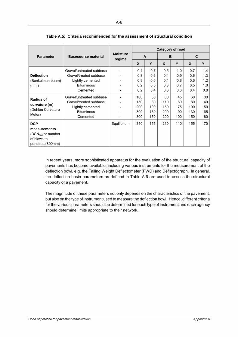
A-6
Code of practice for pavement rehabilitation Appendix A
Table A.5: Criteria recommended for the assessment of structural condition
Parameter Basecourse materialMoistureregime
Category of road
A B C
X Y X Y X Y
Deflection(Benkelman beam)(mm)
Gravel/untreated subbaseGravel/treated subbase
Lightly cementedBituminousCemented
-----
0.40.30.30.20.2
0.70.60.60.50.4
0.50.40.40.30.3
1.00.90.80.70.6
0.70.60.60.50.4
1.41.31.21.00.8
Radius ofcurvature (m)(Dehlen CurvatureMeter)
Gravel/untreated subbaseGravel/treated subbase
Lightly cementedBituminousCemented
-----
100150200300300
6080
100130150
80110150200200
45607590
100
6080
100130150
3040506580
DCPmeasurements(DSN800 or numberof blows topenetrate 800mm)
Equilibrium 350 155 230 110 155 70
In recent years, more sophisticated apparatus for the evaluation of the structural capacity ofpavements has become available, including various instruments for the measurement of thedeflection bowl, e.g. the Falling Weight Deflectometer (FWD) and Deflectograph. In general,the deflection basin parameters as defined in Table A.6 are used to assess the structuralcapacity of a pavement.
The magnitude of these parameters not only depends on the characteristics of the pavement,but also on the type of instrument used to measure the deflection bowl. Hence, different criteriafor the various parameters should be determined for each type of instrument and each agencyshould determine limits appropriate to their network.

A-7
Code of practice for pavement rehabilitation Appendix A
Figure A.3: Criteria for measured maximum surface deflection (Benkelman beam)
Figure A.4: Criteria for measured radius of curvature (Dehlen curvature meter)

A-8
Code of practice for pavement rehabilitation Appendix A
R �r 2
2 δ0 (1 � δr / δ0)
r � 127 mm
[(δ0 � δ1 � δ2 � δ3) / 5] 100δ0
A � 6 [ 1 � 2 ( δ1 / δ0 ) � 2�(δ2 / δ0) � δ3 / δ0]
Table A.6: Summary of the most commonly used deflection bowl parameters
Parameter Formula Measuring device
1. Maximum Deflectionδ0
Benkelman beamLacroix Deflectograph
2. Radius of Curvature
Curvaturemeter
3. Spreadability
Dynaflect
4. AreaFalling weightdeflectometer (FWD)
5. Shape Factors F1 = (δ0 - δ2) / δ1
F2 = (δ1 - δ3) / δ2FWD
6. Surface Curvature Index SCI = (δ0 - δ2), where r = 305 mmor r = 500 mm
Benkelman beamRoad raterFWD
7. Base Curvature Index BCI = δ610 - δ915 Road rater
8. Base Damage Index BDI = δ305 - δ610 Road rater
9. Deflection Ratio Qr = δr / δ0 whereδr�δ0/2
FWD
10. Bending Index BI = δ / a wherea = Deflection Basin Length
Benkelman beam
11. Slope of Deflection SD = tan-1 (δ0 - δr)/rwhere r = 610 mm
Benkelman beam
A.4 Pavement Evaluation Form
All information gathered on the road is taken into account when dividing it into uniformpavement sections. It follows that the information needs to be combined in an easilyunderstandable and manageable format. An example of a form used for this purpose is givenin Figure A.4.

A-9
Code of practice for pavement rehabilitation Appendix A
Figure A.5: Example of a plot of the processed data for the evaluation of pavements
APPENDIX B
PAVEMENT REHABILITATION DESIGNS USED IN SOUTHERNAFRICA: PRINCIPLES AND MAIN CHARACTERISTICS

B-1
Code of practice for pavement rehabilitation Appendix B
APPENDIX B: PAVEMENT REHABILITATION DESIGNS USED INSOUTHERN AFRICA: PRINCIPLES AND MAINCHARACTERISTICS
B.1 Asphalt Institute Method
This method was published in 1969 by the Asphalt Institute9. The design manual covers bothgeometric and structural improvements of pavements in order to increase the traffic capacity,load carrying ability and the safety of the road user.
The manual identifies the following causes of a structurally inadequate pavement:
� Increase in traffic � Change in the pavement material properties � Inadequate design procedures
Different causes of the pavement distress problem are identified, but no distinction is madebetween the recommended approaches to evaluation and rehabilitation design of anypavement. Two empirically derived procedures for the evaluation of structural adequacy andoverlay design are given. These procedures are presented as applicable to all flexiblepavements and any cause and mechanism of distress. The recommended procedures arebased on the pavement component analysis and pavement response analysis (surfacedeflection) approaches.
Although seemingly different, both the recommended procedures are empirically derived andaim at providing adequate protection to the subgrade of the pavement. In this case thepavement rehabilitation problem is approached in a similar way to well-known empiricalmethods used for the design of new pavements, such as the CBR approach. Some subjectiveuse of the existing condition of the pavement is made in the pavement component analysisprocedure.
The main characteristics of the Asphalt Institute method are summarized in Figure B.1 and inTable B.1.

B-2
Code of practice for pavement rehabilitation Appendix B
Figure B.1: Asphalt Institute method for structural design of pavement rehabilitation

B-3
Code of practice for pavem
ent rehabilitationAppendix B
Table B.1: Main characteristics of the Asphalt Institute pavement rehabilitation design method
Developed Basis ofderivation
Classification according toapproach
Pavementevaluation surveys Applicability Input to design LImitations (main) Advantages (main)
AsphaltInstitute inthe USA
Empirical Pavement responseanalysis
1 Deflection-based
2 Pavement componentanalysis
1 Surfacedeflections
2 CBR of subgradeType, thicknessand condition ofpavement layers
- Developed withdata frompavements withgranular sub-layers and thinsurfacing
- Pavementcomponentanalysis methodincorporates alltypes of materialusing conversionfactors andsubjectivecondition ratings
- Surface deflection- Temperature- Past traffic
loading- Future traffic
loading- CBR of subgrade
(DSS)- Type, condition,
thickness ofpavement layers
- Past trafficloading
- Future trafficloading
- Empirically basewith limitations toapplicability
- Design based onprotection ofsubgrade only
- No seasonaladjustment factorsgiven
- AI curve applicableto traffic loading upto 7,3 x 10⁶ E80s
- Componentanalysis procedureapplicable up to36,5 x 106 E80s
- Based on easy-to-apply and well-known concepts
Assumptions Materialcharacterisation Residual life Basis of design life Pavement transfer functions consideration
- Those applicable to deflection-based methods- Deflection-overlay thickness relation incorporates
assumptions of linear elasticity theory- Those applicable to pavement component analysis
method
- The cover requirement of the pavement is independentof the requirements of the individual pavement layers.
- All pavement materials can be converted to anequivalent asphalt thickness.
1 -
2 Uses subjectiveassessment ofthe condition ofpavement layers
1 Use of deflectionversus life curve
2 Uses nomographrelating pavementequivalentthickness to life
- Protection of thesubgrade
- Pavementdeformation
1 Deflection of structure

B-4
Code of practice for pavement rehabilitation Appendix B
B-5
Code of practice for pavement rehabilitation Appendix B
B.2 The DCP Method
The DCP pavement rehabilitation design method8 is empirically derived and based onobservations and experience with the use of the DCP mainly in the Transvaal region of SouthAfrica. The assumptions applicable to the pavement component analysis approach are alsoapplicable to this method. The method was basically developed for use on pavements with thinsurfacing and natural gravel sublayers. However, research has shown that the method canalso be used on pavements with lightly cemented layers (UCS < 3 MPa). Research iscontinued to determine the applicability of this method to pavements other than thoseconsisting of layers with granular materials only.
The method aims at achieving a balanced pavement design and at optimizing the utilizationof the in-situ pavement material strength. This is done through the design of a pavementcapable of carrying the expected future traffic and by comparing the existing pavement DCPproperties with those of the design pavement. Many of the concepts used originated frompractical experience with the use of the instrument and results from HVS tests were used toverify these concepts and to establish structural capacity curves.
The development of these curves was based on a rut depth of 20 mm measured under a 2.0 mstraight-edge which was defined as representing a terminal pavement condition. The designcurves were derived using the mean values measured and are therefore only an indication ofmean expected life.
This design method can lead to various applicable design pavements as several pavementlayer configurations will be capable of carrying a specified design traffic. Therefore, atrial-and-error procedure will have to be used to determine the most economical rehabilitationoption, taking into account the existing pavement structure and the materials locally available.Ample opportunity is allowed for the assessor to incorporate his own experience in the designof applicable rehabilitation alternatives.
The main characteristics of the method are summarized in Figure B.2 and in Table B.2.

B-6
Code of practice for pavement rehabilitation Appendix B
Figure B.2: Dynamic cone penetrometer method for pavement rehabilitation design
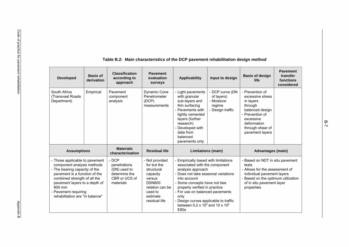
B-7
Code of practice for pavem
ent rehabilitationAppendix B
Table B.2: Main characteristics of the DCP pavement rehabilitation design method
Developed Basis ofderivation
Classificationaccording to
approach
Pavementevaluation
surveysApplicability Input to design Basis of design
life
Pavementtransfer
functionsconsidered
South Africa(Transvaal RoadsDepartment)
Empirical Pavementcomponentanalysis
Dynamic ConePenetrometer(DCP)measurements
- Light pavementswith granularsub-layers andthin surfacing
- Pavements withlightly cementedlayers (furtherresearch)
- Developed withdata frombalancedpavements only
- DCP curve (DNof layers)
- Moistureregime
- Design traffic
- Prevention ofexcessive stressin layersthroughbalanced design
- Prevention ofexcessivedeformationthrough shear ofpavement layers
Assumptions Materialscharacterisation Residual life Limitations (main) Advantages (main)
- Those applicable to pavementcomponent analysis methods
- The bearing capacity of thepavement is a function of thecombined strength of all thepavement layers to a depth of800 mm
- Pavement requiringrehabilitation are "in balance"
- DCPpenetrations(DN) used todetermine theCBR or UCS ofmaterials
- Not providedfor but thestructuralcapacityversusDSN800relation can beused toestimateresidual life
- Empirically based with limitationsassociated with the componentanalysis approach
- Does not take seasonal variationsinto account
- Some concepts have not beeproperly verified in practice
- For use on balanced pavementsonly
- Design curves applicable to trafficbetween 0,2 x 10⁶ and 10 x 106
E80s
- Based on NDT in situ pavementtests
- Allows for the assessment ofindividual pavement layers
- Based on the optimum utilizationof in situ pavement layerproperties

B-8
Code of practice for pavement rehabilitation Appendix B
B.3 The TRL Surface Deflection Method
The pavement evaluation and rehabilitation design method developed at the TransportResearch Laboratory (TRL) was published in 19787. The method is empirically derived anduses surface deflection as a design parameter. It was based on many years of research andexperimental work on roads dating back to 1956.
The main objective of the method is to provide a system for the design ofpavement-strengthening measures that will enable the engineer to:
� Predict the remaining life of a pavement before a critical condition is reached. � Design the thickness of overlay required to extend the life of the pavement to carry a
given design traffic.
The method is based on the characterization of the structural condition of the pavementthrough the measurement of surface deflection. Although all measurements were based ondeflections under a dual wheel load of 3 175 kg moving at creep speed, this can easily beadapted to deflections measured under a Standard axle load. The design manual pays specialattention to the analytical procedures and the correct measurements, adjustment and use ofpavement surface deflections in the various design charts. The method also takes into accountand distinguishes between deflections measured on the main types of roadbase.
The recommended method entails the following:
� Measurement of the surface deflection of the pavement. � Adjustment of the measured deflection. � Estimation of past, present and future expected traffic on the pavement. � Prediction of the residual life of the pavement before reaching a critical condition. � Design of an overlay to extend the life of the pavement to carry the design traffic. � Matching the overlay design to variations in the structural condition of the pavement.
The main characteristics of the TRL deflection method are summarized in Figure B.3 andTable B.3.

B-9
Code of practice for pavement rehabilitation Appendix B
Figure B.3: TRL method for the structural design of pavement rehabilitation

B-10
Code of practice for pavem
ent rehabilitationAppendix B
Table B.3: Main characteristics of the TRL surface defection method
Developed Basis ofderivation
Classificationaccording to
approach
Pavementevaluation
surveysApplicability Input to design Limitations (main) Advantages (main)
UnitedKingdom(TRL)
Empirical Pavementresponse analysis(deflection based)
- Surfacedeflections
- Temperature
- Design chartsdeveloped formain types offlexiblepavement
- Somelimitations ofuse forpavementswithcementedlayers
- Surfacedeflections
- Temperature attime ofmeasurements
- Thickness ofasphalt layer
- Type ofpavement
- Past trafficloading
- Future trafficloading
- Empiricallybased withlimitations inapplicability
- No seasonaladjustmentgiven
- Applicable fortraffic loadingup to 10 x 106
E80s- Design (except
for pavementwith cementedlayers) basedon deformationoriginating fromthe subgradeonly
- Base on easyNDT testing
- Is easy to use- Distinguishes
between the typesof pavement
- Identifies somelimitations in theuse of the methodon pavementswith cementedlayers
- Adjust deflectionsto take the effectof temperaturevariations intoaccount
Assumptions Materialscharacterisation Residual life Basis of design
life Pavement transfer functions considered
- Those applicable to deflection-basedmethods
- Pavement life is a function of type ofpavement and surface deflection
- Use of deflectionversus life curves
Deformation in theform of rut depthexcept forpavements withcemented layerswhere cracking isused as a criterion
Deflection of structure

B-11
Code of practice for pavement rehabilitation Appendix B
B.3 Shell Overlay Design Method
The Shell overlay design method was developed at the Koninklijke Shell Laboratorium inAmsterdam from the Shell design procedure for new pavements11. The charts originallydeveloped for the design of new pavements are also used for the design of asphalt overlaysfor existing pavements. Non-destructive test (NDT) methods are used to assess the propertiesof the existing pavement.
In the Shell method, a number of design charts are used to determine the required thicknessof overlays for the rehabilitation of a pavement. The design charts were derived from theresults of analyses of pavements by means of the theory of linear elasticity. In these analysesthe pavement was assumed to be adequately represented by a three-layered model consistingof a top layer (surfacing) of asphaltic material, a middle layer (base) of granular or cementitiousmaterial and a bottom layer (subgrade) of semi-infinite dimensions as shown in Figure B.4. Inthis model the pavement materials are characterized by the following properties:
� Surfacing layer: the effective modulus of deformation (E1 value), a Poisson's ratio(v1) and a layer thickness (h1).
� Base layer: the effective modulus of deformation (E2 value), a Poisson's ratio(v2) and a layer thickness (h2).
� Subgrade layer: the effective modulus of deformation (E3 value) and a Poisson's ratio(v3) (the layer thickness is assumed to be infinite).
Figure B.4: Simplified pavement structure

B-12
Code of practice for pavement rehabilitation Appendix B
In the development of the method, the BISAR computer program was used to calculate thestresses and strains in pavement structures. The results obtained were used to compile thedesign charts. The primary design criteria used for the compilation of these charts were the:
� Compressive vertical strain in the surface of the subgrade which controls deformationof the subgrade material.
� Horizontal tensile strain in the asphalt layer which controls cracking of the asphalt layer. � Tensile stress of strain in any cementitious base layer which controls cracking of the
cementitious layer.
In the evaluation of pavements using the derived charts, fixed values are assumed for thePoisson's ratios for all the layers. Falling Weight Deflectometer (FWD) measurements,material tests and available data are used to determine the other in-situ properties. Themaximum deflection and the shape of the deflection bowl, as measured by the FWD, are usedto determine the subgrade modulus (E3) and the effective thickness of the asphalt layer (h1).The deflection bowl is characterized by the ratio (Qr) of the deflection at a distance r from theload (sr) to the deflection under the centre of the test load (so). The distance r shouldpreferably be such that Qr ~ 0.5.
The design charts ensure that the strains (mentioned above) are limited to such an extent thatvirtually no cracking will occur in the structure and that there will be no excessive permanentdeformation in the subgrade during the design life of the pavement.
Practical constrains made it impossible to develop design charts for every conceivablepavement configuration. Hence, the method will often require design charts to be interpolatedfor overlay design. The use of such charts eliminates the need to calculate the criticalparameters of the pavement through computer simulation of the pavement response.
Although the design approach is based on the above mentioned strain criteria, the Shellmethod also provides for the testing of the expected permanent deformation in the asphaltlayer and for checking of the maximum overlay thickness. Provision is made to include climaticvariations (temperature changes) in the design of the overlay. Procedures included in themethod take into account the variations in asphalt mix properties available for overlays andassess their differences in comparison with the asphalt on the existing pavement and theirinfluence on the expected future behaviour of the rehabilitated pavement.
The main characteristics of the Shell overlay design method are summarized in Figure B.5 andTable B.4.
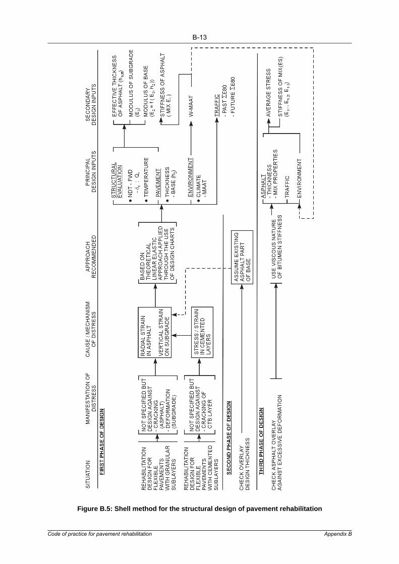
B-13
Code of practice for pavement rehabilitation Appendix B
Figure B.5: Shell method for the structural design of pavement rehabilitation

B-14
Code of practice for pavem
ent rehabilitationAppendix B
Table B.4: Main characteristics of the Shell overlay design method
Developed Basis ofderivation
Classificationaccording to
approach
Pavementevaluation
surveysApplicability Input to design Limitations (main) Advantages (main)
TheNetherlands(KoninklijkeShellLaboratoriumAmsterdam)
Theoretical(linearelasticitytheory)
Application throughthe use of designcharts
Falling weightDeflectometer(FWD)
All types offlexiblepavements(specialprovision forcementitiouslayers)
- Maximumdeflection
- Deflection ratio(Qr)
- Temperature
- Incorporatesonlytemperaturechanges - as aclimate effect
- Does notassessunboundpavementlayers
- Charts basedon asphaltfatigue andsubgradedeformationonly
- Bases on NDT tests- Tests overlay mix
properties intoaccount
- Incorporates andallows fortemperaturegradients in theasphalt layer
- Allows for thechecking ofdeformation inasphalt layers
- Incorporates differentclimates through w-MAAT factor
Assumptions Materialscharacterisation Residual life Basis of design
life Pavement transfer functions considered
- Those applicable to linear elasticity theory- Distress = f (asphalt strain, subgrade strain)- Modulus of base is a function of modulus of
subgrade and the thickness of the base layer- Poisson's ratio for all layers = 0,35
Use NDT (FWD)measurements- maximum
deflections (σ)- deflection
ratio (Qr)- temperature- thickness of
base (h2)
Use FWDmeasurementsbetween thewheel tracks todetermine asbuilt pavementlife from designcharts
- Tensile strainin asphalt
- Compressivestrain insubgrade
- Viscous-natureof asphalticmaterial
- Deflection basin- Asphalt tensile strain- Subgrade compressive stress

B-15
Code of practice for pavement rehabilitation Appendix B
B.4 The South African Mechanistic Design Method
The South African mechanistic rehabilitation design method12 was developed at the Divisionof Roads and Transport Technology, CSIR. It incorporates experience in pavement behaviourgathered through many years of accelerated pavement testing with the fleet of Heavy VehicleSimulators (HVSs).
The method is based on the theory of linear elasticity. In practice, this theory is applied topavement analysis through the use of a catalogue of behaviour states or, alternatively, througha computer-aided simulation of the response of the pavement under loading. The catalogueincludes assessments of the behaviour and condition of a large number of pavements.Information is given on average values for several pavement indicators and on possible visualdistress, recommended test methods, recommended analysis methods and possiblerehabilitation options. Therefore, the catalogue can be used to do a comprehensive analysisof a pavement. The theory of linear elasticity as well as results and experience gained overmany years of HVS testing have been combined to compile the catalogue.
A prerequisite for the use of the method is the identification of the class, type and state of thepavement and the state of the pavement materials as shown in Figure B.6. The material ineach pavement layer is classified and material properties are assigned to each pavement layerthrough the use of published values selected from tables. These tables were compiled frompractical experience with HVS testing and from the theoretical analysis of pavement undervarious conditions. (Naturally, elastic properties obtained by means of other procedures mayalso be used.) The state of the pavement and the material properties are used in the catalogueof behaviour states to identify and correlate the condition of the existing pavement with one ofthe analysed pavements from the catalogue. The assessor is advised only to do acomputer-aided analysis of the pavement when no correlation can be achieved.
The method relies strongly on the correct identification of the current state and condition of thepavement. The role of specialized tests to assist in the identification of the behaviour state isdiscussed. These tests are not used for the direct characterization of material properties andpavement behaviour. Instead the pavement class, type and state as well as the material stateare used somewhat subjectively to assign pavement properties to the different layers. Due tothe emphasis on pavement behaviour, much effort is put into a detailed description of thechange in behaviour with time and traffic loading. All the main flexible types of pavement(granular, cemented and bituminous) are discussed and changes in conditions, such as in thepavement layer state, are also taken into account.

B-16
Code of practice for pavement rehabilitation Appendix B
Figure B.6: Identification of the state and condition of a pavement

B-17
Code of practice for pavement rehabilitation Appendix B
In a computer-aided analysis the material properties already assigned are used in computerprograms to calculate the critical distress parameters. The modulus of deformation (E),Poisson's ratio (v) and thickness (h) of each layer (subgrade considered as semi-infinite inthickness) are used in any of a number of available programs based on the theory of linearelasticity. The calculated critical parameters (stresses, strains and deformations) are weightedagainst limiting criteria to determine the need to strengthen the pavement. No method is givento determine directly the thickness of overlay, if applicable, or the amount and type ofstrengthening required. Rehabilitation options(e.g. thickness of an overlay) are determinedthrough estimation or trial and error.
The method provides for a comprehensive theoretical analysis of various possible materialconditions for the different pavement types. This method is one of the few that allows for theevaluation of all the types of pavement material in all the pavement layers, such as granularmaterials in a base or subbase layer. However, no provision is made for evaluation of possiblepermanent deformation in asphalt layers or of the pavement as a whole.
Although the method recognizes the importance of environmental changes such astemperature and moisture, no procedure is given for the inclusion of these factors in therehabilitation design.
The main characteristics of the South African mechanistic design method are given inFigure B.7 and Table B.5.

B-18
Code of practice for pavement rehabilitation Appendix B
Figure B.7: SA mechanistic method for the structural design of pavement rehabilitation

B-19
Code of practice for pavem
ent rehabilitationAppendix B
Table B.5: Main characteristics of the South African mechanistic rehabilitation design method
Developed Basis ofderivation
Classificationaccording to
approach
Pavementevaluation
surveysApplicability Input to
design Limitations (main) Advantages (main)
South African(NITRR)
Theoretical (Linearelasticity theory)
1 Applicationthrough the useof a catalogueof behaviourstates oralternatively
2 Non-simplifiedapproach usingcomputerassistedsimulation
- Deflections- Cores- Test pits
All flexible andrigid types ofpavement
- Pavementclass
- Pavementtype
- Pavementstate
- Pavementlayer state
- Catalogue includes alimited number ofanalyses covering onlythe main trends inbehaviour
- No direct procedure ofmaterial characterizationis given
- Does not take intoaccount variations inenvironmental conditions
- Does not take intoaccount past life of thepavement
- Allows foranalysis of alltypes ofmaterial in alltype of layers
- Allows foranalysis ofpavements withthin asphaltlayers
Assumptions Materialscharacterisation Residual life Basis of design life Pavement transfer functions considered
- Thoseapplicable tothe use oflinearelasticitytheory
- State of thepavement isa function ofsurfacedeflection
Assign moduli fromtables using:- state of
material- state of
pavement- type of material
Not discussed but:1 Catalogue difficult to use for the
assessment of residual life2 Non-simplified approach is used
for the assessment of variousdistress parameters and thus forprediction of residual life
- Bituminous layers:Tensile strain at bottom oflayer
- Cemented layers:Tensile strain at bottom oflayer
- Granular layers:Stress state of layer
- Subgrade:Vertical strain at the top ofthe layer
- Stress in granular materials- Strain in bituminous and cementitious materials

APPENDIX C
CONCEPTS IN DECISION THEORY

C-1
Code of practice for pavement rehabilitation Appendix C
E(α) � P1 θ1 � P2 θ2 � P3 θ3
� �i
Pi θi
where �i
Pi � 1
APPENDIX C: CONCEPTS IN DECISION THEORY
The object of this Appendix is to give a basic introduction to the concepts of Bayesian analysisand decision trees recommended for use in the economic appraisal of alternative rehabilitationoptions.
In pavement rehabilitation design there is considerable doubt about the condition of thepavement after a certain period. This is due to various uncertainties such as variations in thequality of material and in construction techniques, and uncertain traffic conditions. To allow forpossible deterioration in the condition of the pavement, a technique is introduced whereby thepossibility of different outcomes after a certain period of time is included in the analysis.
This approach allows subjective judgment, based on experience of conditions and materials,to be incorporated in the system with observed data to obtain a balanced estimation of theexpected cost of an alternative. For any given action (rehabilitation option) the engineer oftenhas some knowledge of the possible outcome or outcomes (conditions) to be expected aftera certain period of time. He may also expect one outcome to be more likely to occur thanothers, and therefore could subjectively assign probabilities of occurrence to each possibleoutcome.
For example, in Figure C.1 an illustration of a branch of a decision tree, a given action a mayhave three possible outcomes with values θ1, θ2 and θ3, which, it is judged, may occur withrespective probabilities of P1, P2, and P3.
Figure C.1: Example of a given act with three possible outcomes
In this case the expected value of α is given as:
...Equation C.1

C-2
Code of practice for pavement rehabilitation Appendix C
In practice one action is generally followed by another after a certain time, for example anoverlay is followed by a seal when the overlay is cracked after a time. The principle illustratedin Figure C.1 may now be extended to include a further action with its own possible outcomes,as illustrated in the decision tree in Figure C.2. The information in Figure C.2 is contained inTable C.1.
Table C.1: Resultant outcomes and actions for two time periods for any one initial action
Initial Act Probability Outcome Second Act Probability Outcome
α1
P11 θ11
b11P1111
P1112
θ1111
θ1112
b112P1121
P1122
θ1121
θ1122
P12 θ12
b121P1211
P1212
θ1211
θ1212
b122
P1221
P1222
P1232
θ1221
θ1222
θ1232
b123P1231
P1232
θ1231
θ1232
P13 θ13
b131P1311
P1312
θ1311
θ1312
b132P1321
P1322
θ1321
θ1322

C-3
Code of practice for pavement rehabilitation Appendix C
Figure C.2: Decision tree with outcomes and possible second acts for two time periods

C-4
Code of practice for pavement rehabilitation Appendix C
� �i
Pli max (�j
P1i1j θ1i1j ; �j
P1i2j θ1i2j ; �j
P1i3j θ1i3j )
where �i
Pli � 1
�j
P1i1j � 1 ; �j
P1i2j � 1 ; �j
P1i3j θ1i3j � 1
The expected value of the example contained in Table C.1 is given as:
E(α1) = P11 max {(P1111 θ1111 + P1112 θ1112) ; (P1121 θ1121 + P1122 θ1122)}
+ P12 max {(P1211 θ1211 + P1212 θ1212) ; (P1221 θ1221 + P1222 θ1222
+ P1223 θ1223) ; (P1231 θ1231 + P1232 θ1232)}
+ P13 max {(P1311 θ1311 + P1312 θ1312) ; (P1321 θ1321 + P1322 θ1322)}
...Equation C.2
The example illustrated in Figure C.2 and Table C.1 represents the analysis of onerehabilitation alternative only. All appropriate options should be analysed in a similar manner.The expected values of each appropriate option, analysed over the same period, may then becompared to determine the option with the lowest expected value.

APPENDIX D
EXAMPLE: ECONOMIC ANALYSIS
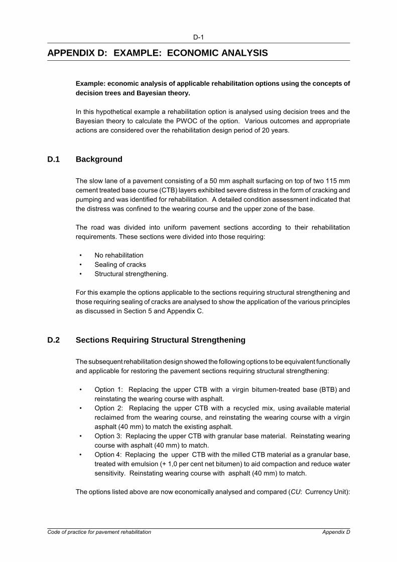
D-1
Code of practice for pavement rehabilitation Appendix D
APPENDIX D: EXAMPLE: ECONOMIC ANALYSIS
Example: economic analysis of applicable rehabilitation options using the concepts ofdecision trees and Bayesian theory.
In this hypothetical example a rehabilitation option is analysed using decision trees and theBayesian theory to calculate the PWOC of the option. Various outcomes and appropriateactions are considered over the rehabilitation design period of 20 years.
D.1 Background
The slow lane of a pavement consisting of a 50 mm asphalt surfacing on top of two 115 mmcement treated base course (CTB) layers exhibited severe distress in the form of cracking andpumping and was identified for rehabilitation. A detailed condition assessment indicated thatthe distress was confined to the wearing course and the upper zone of the base.
The road was divided into uniform pavement sections according to their rehabilitationrequirements. These sections were divided into those requiring:
� No rehabilitation � Sealing of cracks � Structural strengthening.
For this example the options applicable to the sections requiring structural strengthening andthose requiring sealing of cracks are analysed to show the application of the various principlesas discussed in Section 5 and Appendix C.
D.2 Sections Requiring Structural Strengthening
The subsequent rehabilitation design showed the following options to be equivalent functionallyand applicable for restoring the pavement sections requiring structural strengthening:
� Option 1: Replacing the upper CTB with a virgin bitumen-treated base (BTB) andreinstating the wearing course with asphalt.
� Option 2: Replacing the upper CTB with a recycled mix, using available materialreclaimed from the wearing course, and reinstating the wearing course with a virginasphalt (40 mm) to match the existing asphalt.
� Option 3: Replacing the upper CTB with granular base material. Reinstating wearingcourse with asphalt (40 mm) to match.
� Option 4: Replacing the upper CTB with the milled CTB material as a granular base,treated with emulsion (+ 1,0 per cent net bitumen) to aid compaction and reduce watersensitivity. Reinstating wearing course with asphalt (40 mm) to match.
The options listed above are now economically analysed and compared (CU: Currency Unit):

D-2
Code of practice for pavement rehabilitation Appendix D
D.2.1 Option 1Removal of wearing course by milling, milling of upper 100 mm of CTB, replacing removedCTB with a BTB (90 mm) and replacing asphalt wearing course.
Unit costsMilling of asphalt (30 mm) : CU 0.44/m3
Milling of CTB (100 mm) : CU 17.68/m3
Hauling of milled CTB to spoil (10 km) : CU 7.00/m3
BTB supply & compact : CU 120.00/tAsphalt wearing course : CU 130.00/t
Costs calculated per km for 3.7 m lane widthMilling of asphalt : CU 1 628.00 Milling of CTB : CU 6 541.60Hauling of CTB to spoil (includes 1.3 bulk factor) : CU 3 174.60BTB, supply and place : CU 91 908.00 Asphalt wearing course : CU 44 252.00
Total/lane/km CU 147 504.20
Costs which will be common to all rehabilitation options being investigated, e.g. transportationof milled wearing course and possible seal on top of new asphalt wearing course (for uniformityof texture), have not been included in the economic comparison.
D.2.2 Option 2Removal of wearing course by milling, milling of upper 100 mm of CTB, replacing the removedCTB with a BTB using reclaimed wearing course to constitute 25 per cent of the new mix,reinstating the asphalt wearing course.
Unit costsMilling of asphalt (30 mm) : CU 0.44/m2
Milling of CTB (100 mm) : CU 17.68/m3
Hauling of milled CTB to spoil (10 km) : CU 7.00/m3
Recycled asphalt (BTB) : CU 100.00/tAsphalt wearing course : CU 130.00/t
Costs calculated per km for 3.7 m lane widthMilling of asphalt : CU 1 628.00Milling of CTB : CU 6 541.60Hauling of CTB to spoil (10 km) : CU 3 174.60Asphalt (90 mm) : CU 76 590.00Asphalt wearing course : CU 44 252.00
Total/lane/km CU 132 186.20
D.2.3 Option 3Removal of wearing course by milling, milling of upper 100 mm of CTB, replacing removedCTB with crushed stone granular base (G2) and replacing wearing course.
Unit costsMilling of asphalt (30 mm) : CU 0.44/m2
Milling of CTB (100 mm) : CU 17.68/m3

D-3
Code of practice for pavement rehabilitation Appendix D
Hauling of milled CTB to spoil (10 km) : CU 7.00/m3
G2 crushed B/C (90 mm) : CU 60.00/m3
Asphalt wearing course (40 mm) : CU 130.00/t
Costs calculated per km for 3.7 m lane widthMilling of asphalt : CU 1 628.00Milling of CTB : CU 6 541.60Hauling of CTB to spoil : CU 3 174.60G2 crushed B/C : CU 19 980.00Asphalt wearing course : CU 44 252.00
Total/lane/km CU 75 576.20
D.2.4 Option 4Removal of wearing course by milling, milling of upper 100 mm CTB, retaining milled materialand recompacting with emulsion (+ 1,0 per cent net bitumen), replacing asphalt wearingcourse.
Unit costsMilling of asphalt (10 mm) : CU 0.44/m2
Milling of CTB (100 mm) : CU 17.68/m3
Addition of emulsion(1.0% net, bit,ncl. spraying, mixing & compaction) : CU 26.00/m3
Compaction of B/C : CU 6.00/m3
Asphalt wearing course (40 mm) : CU 130.00/t
Costs calculated per km for 3.7 m lane widthMilling of asphalt (30 mm) : CU 1 628.00Milling of CTB (100 mm) : CU 6 541.60Addition of emulsion : CU 8 658.00Mixing and compaction : CU 1 988.00Asphalt wearing course (40 mm) : CU 44 252.00
Total/lane/km CU 63 077.60
From the above it is clear that for Options (3) and (4) the initial costs are significantly lower thanfor the other options considered.
Past experience has shown that there should not be any significant difference in the expectedlife of any of the options and hence (1), (2) and (3) are rejected for economical reasons.
Option (3) has an initial cost 20 per cent greater than that of Option (4). As no real differencecan be expected in the salvage value between the options, nor any difference in maintenanceduring the design life, the initial costs may in this case be used for comparison without adetailed economic analysis.
Option (4), is thus recommended for those sections identified for rehabilitation.

D-4
Code of practice for pavement rehabilitation Appendix D
D.3 Sections Requiring Resealing
These sections are structurally sound but have open cracks allowing for the ingress of waterinto the pavement. Although it was considered likely that a conventional seal would proveadequate for sealing these pavement sections, other applicable options such as a bitumenrubber seal or the option to postpone treatment ("do nothing now") should also be investigated.
Unit costs assumed for the economic comparisons of the various options (given per km for3.7 m width) are:
� Rehabilitation (according to Option (4) in the preceding section) - CU 63 000/km � Conventional 9.5 mm reseal (CU 2.60/m2) - CU 9 600/km � Bitumen rubber 9.5 mm reseal - CU 16 280km
(2.7 �/m2, 1.04 CU/� sprayed, 1.60 CU/m2 chipping)
D.3.1 Salvage Value CostsThe "salvage value cost" is the cost of rehabilitation required at the end of the analysis periodfor each option which would theoretically reinstate the road to a similar "end" condition. In thiscase it was decided to "reinstate" the road to a freshly rehabilitated condition, e.g. having anuncracked surface.
An accelerated test showed that even if the surfacing is kept sealed against the ingress ofwater, the slow lane, under its expected traffic loading, will deform to a terminal state in 20years (requiring rehabilitation). Should the pavement be susceptible to water ingress, thepavement is expected to reach a terminal condition within five years.
D.3.2 Option 1: "do nothing"If no remedial action is taken to seal these pavement sections, it is assumed that the pavementwill require rehabilitation after an additional five years.
For this option (do nothing at present - refer to Figure D.1) two conditions are consideredpossible after five years, i.e.:
� Condition 1A: cracked and deformed condition with the probability of occurrencebeing 70 per cent (subjectively determined)
� Condition 1B: cracked condition (severe cracking and pumping) with the probabilityof occurrence being 30 per cent (subjectively determined).
If the pavement is cracked and deformed after five years (Option 1A), it will have to berehabilitated (according to approach already recommended).
After a further 10 years the rehabilitated pavement may be cracked (Option 1A1, 40 per centprobability) or it may be in a sound condition (Option 1A2, 60 per cent probability).
For the cracked condition (Option 1A1) two options are considered, i.e. a conventional reseal(Option 1A1/1), which at year 20 should be sound (100 per cent), or alternatively to do nothing(Option 1A1/2), which at year 20 may be cracked (40 per cent) or cracked and deformed (60per cent). For the sound condition (Option 1A2) no remedial action is deemed necessary andit is considered that at year 20 it may be cracked (70 per cent probability) or sound (30 percent probability).

D-5
Code of practice for pavement rehabilitation Appendix D
A similar approach of reasoning to the above is adopted for the other two options which areanalysed in this example.
The analysis is done using a discount rate of 6 per cent.
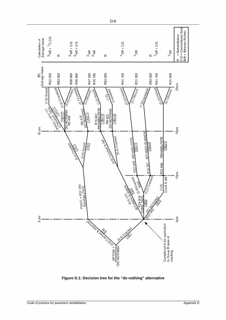
D-6
Code of practice for pavement rehabilitation Appendix D
Figure D.1: Decision tree for the “do nothing” alternative

D-7
Code of practice for pavement rehabilitation Appendix D
Condition 1A: Pavement Cracked and DeformedAbbreviations used: I/C = initial cost
B/R = bitumen rubberC/S = conventional sealR = rehabilitation
1S1/1: Initial Cost of Conventional Seal (discounted for 15 years at 6 per cent p.a.) +(EProbability of occurrence X salvage value costs discounted for 20 years).
= I/C C/S (15 yrs) + 1.0 (CU 52 050) (20 yrs)= (CU 9 600) (1.06) - 15 + 1.0 (CU 52 050)(1.06) - 20 = CU 4 004 + CU 16 228= CU 20 234/km
1A1/2: I/C nil (15yrs) + 0.6 (CU 63 000)(20yrs) + (CU 56 860)(20yrs) = nil + 0.6 (CU 63 000)(1.06) - 20 + (CU 56 860)(1.06) - 20 = nil + CU 11 7860 + CU 7 092 = CU 18 878/km
1A2/1:I/C nil (15yrs) + 0.7 (CU 56 860)(20 yrs) + 0.3 (CU 47 260)(20 yrs)= nil + 0.7 (CU 56 860)(1.06) - 20 + 0.3 (CU 47 260)(1.06) - 20= nil + CU 12 410 + CU 4 420= CU 16 830/km
1A: I/C R (5yrs) + 0.4 (CU 18 878) + 0.6 (CU 16 830)= (CU 63 000)(1.06) - 5 + 0.4 (CU 18 878) + 0.6 (CU 16 830)= CU 47 080 + CU 7 552 + CU 10 098= CU 64 730/km
Condition 1B: Pavement Cracked1B1/1: I/C R (15yrs) + 1.0 (CU 15 760)(20yrs)= (CU 63 000)(1.06) - 15 + 1.0 (CU 15 760)(1.06) - 20= CU 26 288 + CU 4 914= CU 31 202/km
1B1/2: I/C nil + 1.0 (CU 63 000)(20yrs)= nil + CU 19 644= CU 19 644/km
1B1: I/C B/R (5yrs) + 0.6 (CU 31 202) + 0.4 (CU 19 644)= CU 16 280 (1.06) - 5 + 0.6 (CU 31 202) + 0.4 (CU 19 644)= CU 38 746/km
1B2/1: I/C R (10 yrs) + 0.3 (CU 41 100) (20 yrs) + 0.7 (CU 31 500)(20 yrs)= CU 63 000 (1.06) - 10 + CU 3 844 + CU 6 876= CU 45 898/km
1B2/2: I/C (10 yrs) + 1.0 (CU 63 000) (20 yrs)= (CU 16 280) (1.06) - 10 + 1.0 (CU 63 000)(1.06) - 20= CU 28 734/km
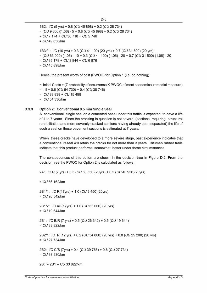
D-8
Code of practice for pavement rehabilitation Appendix D
1B2: I/C (5 yrs) + 0.8 (CU 45 898) + 0.2 (CU 28 734)= (CU 9 600)(1.06) - 5 + 0.8 (CU 45 898) + 0.2 (CU 28 734)= CU 7 174 + CU 36 718 + CU 5 746= CU 49 638/km
1B3:/1: I/C (10 yrs) + 0.3 (CU 41 100) (20 yrs) + 0.7 (CU 31 500) (20 yrs)= (CU 63 000) (1.06) - 10 + 0.3 (CU 41 100) (1.06) - 20 + 0.7 (CU 31 500) (1.06) - 20= CU 35 178 + CU 3 844 + CU 6 876= CU 45 898/km
Hence, the present worth of cost (PWOC) for Option 1 (i.e. do nothing)
= Initial Costs + (Σ probability of occurrence X PWOC of most economical remedial measure)= nil + 0.6 (CU 64 730) + 0.4 (CU 38 746)= CU 38 838 + CU 15 498= CU 54 336/km
D.3.3 Option 2: Conventional 9.5 mm Single SealA conventional single seal on a cemented base under this traffic is expected to have a lifeof 4 to 7 years. Since the cracking in question is not severe (sections requiring structuralrehabilitation and more severely cracked sections having already been separated) the life ofsuch a seal on these pavement sections is estimated at 7 years.
When these cracks have developed to a more severe stage, past experience indicates thata conventional reseal will retain the cracks for not more than 3 years. Bitumen rubber trailsindicate that this product performs somewhat better under these circumstances.
The consequences of this option are shown in the decision tree in Figure D.2. From thedecision tree the PWOC for Option 2 is calculated as follows:
2A: I/C R (7 yrs) + 0.5 (CU 50 550)(20yrs) + 0.5 (CU 40 950)(20yrs)
= CU 56 162/km
2B1/1: I/C R(17yrs) + 1.0 (CU 9 450)(20yrs)= CU 26 342/km
2B1/2: I/C nil (17yrs) + 1.0 (CU 63 000) (20 yrs)= CU 19 644/km
2B1: I/C B/R (7 yrs) + 0.5 (CU 26 342) + 0.5 (CU 19 644)= CU 33 822/km
2B2/1: I/C R (12 yrs) + 0.2 (CU 34 800) (20 yrs) + 0.8 (CU 25 200) (20 yrs)= CU 27 734/km
2B2: I/C C/S (7yrs) + 0.4 (CU 39 766) + 0.6 (CU 27 734)= CU 38 930/km
2B: = 2B1 = CU 33 822/km
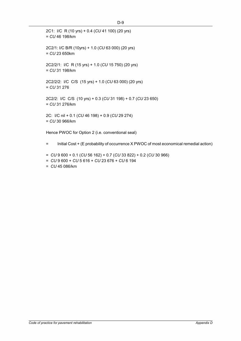
D-9
Code of practice for pavement rehabilitation Appendix D
2C1: I/C R (10 yrs) + 0.4 (CU 41 100) (20 yrs)= CU 46 198/km
2C2/1: I/C B/R (10yrs) + 1.0 (CU 63 000) (20 yrs)= CU 23 650km
2C2/2/1: I/C R (15 yrs) + 1.0 (CU 15 750) (20 yrs)= CU 31 198/km
2C2/2/2: I/C C/S (15 yrs) + 1.0 (CU 63 000) (20 yrs)= CU 31 276
2C2/2: I/C C/S (10 yrs) + 0.3 (CU 31 198) + 0.7 (CU 23 650)= CU 31 276/km
2C: I/C nil + 0.1 (CU 46 198) + 0.9 (CU 29 274)= CU 30 966/km
Hence PWOC for Option 2 (i.e. conventional seal)
= Initial Cost + (E probability of occurrence X PWOC of most economical remedial action)
= CU 9 600 + 0.1 (CU 56 162) + 0.7 (CU 33 822) + 0.2 (CU 30 966)= CU 9 600 + CU 5 616 + CU 23 676 + CU 6 194= CU 45 086/km
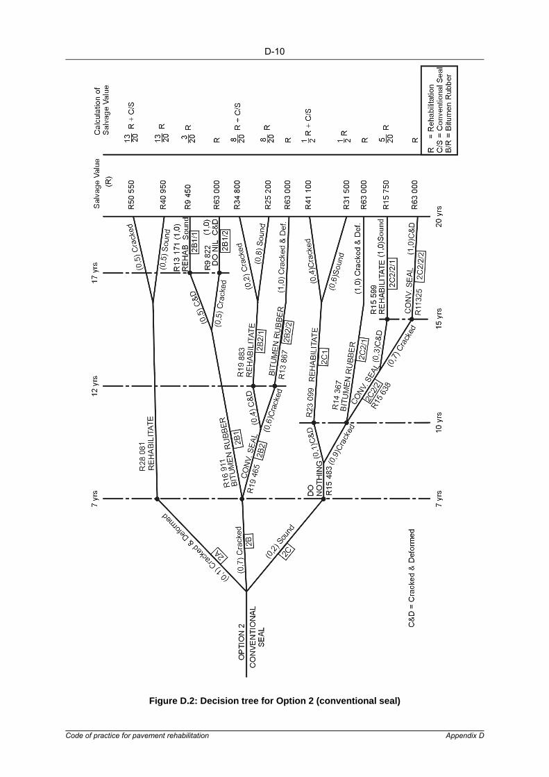
D-10
Code of practice for pavement rehabilitation Appendix D
Figure D.2: Decision tree for Option 2 (conventional seal)

D-11
Code of practice for pavement rehabilitation Appendix D
D.3.4 Option 3: Bitumen Rubber SealThe pavement sections under consideration are structurally sound and the cracking is notsevere. Hence, the bitumen rubber, if used on these sections, will not be required to providea structural contribution.
Following the decision tree in Figure D.3 for the option, the PWOC is calculated according tothe procedure used for Options 1 and 2 above.
Option 3(a) assumes that the bitumen rubber could have an extra life of 50 per cent over thatof the conventional seal (i.e. 10 years as compared with 7 years) on this section with no severecracking.
3A: I/C R (10 yrs) + 0.4 (CU 41 100)(20 yrs) + 0.6 (CU 31 500)(20 yrs)
= CU 46 198/km
3B1: I/C R (10 yrs) + 1.0 (CU 63 000)(20 yrs)= CU 28 734/km
3B/2/1: I/C R (15 yrs) + 1.0 (CU 15 750)(20 yrs)= CU 31 198/km
3B2/2: I/C C/R (15 yrs) + 1.0 (CU 63 000)(20 yrs)= CU 23 650/km
3B2: I/C C/S (10 yrs) + 0.4 (CU 31 198) + 0.6 (CU 23 650)= CU 31 998/km
3B: 3B1 = CU 28 734/km
3C1/1: I/C R (15 yrs) + 1.0 (CU 15 750)(20 yrs)= CU 31 198/km
3C1/2: I/C C/S (15 yrs) + 1.0 (CU 63 000)(20 yrs)= CU 23 648/km
3C1: I/C nil (10 yrs) + 0.4 (CU 31 198) + 0.6 (CU 23 650)= CU 26 670/km
Hence PWOC for Option 3(a) i.e. sealing with bitumen rubber= Initial Costs + (E probability of occurrence X PWOC of most economical remedial
measure)= I/C B/R + 0.1 (CU 46 198) + 0.7 (CU 28 734) + 0.2 (CU 26 670)= CU 16 280 + CU 4 620 + CU 20 114 + CU 5 334= CU 46 348/km (assuming that the bitumen rubber could have an extra life of 50 per cent overthe conventional seal over not too severe cracks).
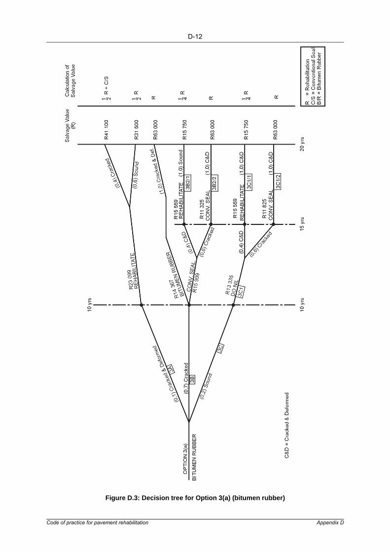
D-12
Code of practice for pavement rehabilitation Appendix D
Figure D.3: Decision tree for Option 3(a) (bitumen rubber)

D-13
Code of practice for pavement rehabilitation Appendix D
Option 3(b) assumes that, while the cracks are only of a lesser severity and no structuralvalue is required from the bitumen rubber, the weathering characteristics of the bitumen rubberare the critical criterion. The assumption is that the bitumen rubber will oxidise within thesame period as the conventional seal (since there is no proof to the contrary at present). Whenthe cracking has become more severe it is suggested that the bitumen rubber will performbetter than a conventional seal.
Hence, using the decision tree used for Option 2, only the initial cost changes. It follows that:
PWOC for Option 3(b) = CU 51 766/km.
Discussion of options for pavement sections exhibiting less severe cracking:
Option 1 - "do nothing now" : CU 54 336/kmOption 2 - conventional seal : CU 45 086/km
Option 3(a) bitumen rubber (assuming a 50 per cent longer life on not severe cracks) :CU 46 348/km
Option 3(b) bitumen rubber (assuming no longer life on not severe cracks): CU 51 766/km
From the above results of the economic analysis of the various options it is clear that the "donothing" option is not to be recommended.
The most economical option was found to be a conventional seal.
The use of bitumen rubber only becomes economically equivalent to a conventional seal if itcan be assured that at least a 50 per cent increase in life will be achieved on the pavementsections exhibiting less severe cracking.