Dr. Tauseef Aized Flexible manufacturing system: hardware...
17
Flexible manufacturing system: hardware components 1 X Flexible manufacturing system: hardware components Dr. Tauseef Aized Professor, Department of Mechanical , Mechatronics and Manufacturing Engineering, KSK Campus, University of Engineering and Technology, Lahore, Pakistan A flexible manufacturing system is a highly automated system consisting of a group of workstations interconnected by an automated material handling and storage system and controlled by a distributed computer system. It is capable of processing a variety of different part styles simultaneously at various workstations and the mix of part styles and quantities of production can be adjusted in response to changing demand patterns. A flexible manufacturing system comprises of processing stations, material handling and storage systems and requires hardware and software provisions. The hardware components typically required for a FMS are; Machine tools, for example, machining centers, turning centers, etc. Load/unload stations Guided vehicles Robots Inspection facilities like coordinate measuring machines Programmable Logic Controllers (PLC). This chapter describes the hardware provisions required for a flexible manufacturing system. Introduction Flexible manufacturing systems consist of hardware and software components. The hardware components typically comprise of processing stations, material handling systems and automated material storage and retrieval systems. The processing stations are the workstations that perform different operations on part families. These workstations are CNC machine tools, inspection equipments, assembly stations and material loading/ unloading areas. Material handling systems include automated guided vehicle systems, roller conveyors, tow line, shuttle cars etc whereas automated storage and retrieval systems are used to store and retrieve work parts automatically. Various types of storage and retrieval systems are pallets, carousels etc which help in convenient access of different types of parts from stores and increase machine utilization of flexible manufacturing systems. The 1 www.intechopen.com
Transcript of Dr. Tauseef Aized Flexible manufacturing system: hardware...
Flexible manufacturing system: hardware components 1
Flexible manufacturing system: hardware components
Dr. Tauseef Aized
X
Flexible manufacturing system: hardware components
Dr. Tauseef Aized
Professor, Department of Mechanical , Mechatronics and Manufacturing Engineering, KSK Campus, University of Engineering and Technology, Lahore, Pakistan
A flexible manufacturing system is a highly automated system consisting of a group of workstations interconnected by an automated material handling and storage system and controlled by a distributed computer system. It is capable of processing a variety of different part styles simultaneously at various workstations and the mix of part styles and quantities of production can be adjusted in response to changing demand patterns. A flexible manufacturing system comprises of processing stations, material handling and storage systems and requires hardware and software provisions. The hardware components typically required for a FMS are;
Machine tools, for example, machining centers, turning centers, etc. Load/unload stations Guided vehicles Robots Inspection facilities like coordinate measuring machines Programmable Logic Controllers (PLC).
This chapter describes the hardware provisions required for a flexible manufacturing system.
Introduction
Flexible manufacturing systems consist of hardware and software components. The hardware components typically comprise of processing stations, material handling systems and automated material storage and retrieval systems. The processing stations are the workstations that perform different operations on part families. These workstations are CNC machine tools, inspection equipments, assembly stations and material loading/ unloading areas. Material handling systems include automated guided vehicle systems, roller conveyors, tow line, shuttle cars etc whereas automated storage and retrieval systems are used to store and retrieve work parts automatically. Various types of storage and retrieval systems are pallets, carousels etc which help in convenient access of different types of parts from stores and increase machine utilization of flexible manufacturing systems. The
1
www.intechopen.com

Future Manufacturing Systems2
processing and assembly equipments used in a flexible manufacturing system depend upon the type of work being accomplished by the system. In a system designed for machining operations, the principal types of processing stations are CNC machines like CNC machining and turning centers. However, the FMS concept is applicable to various other processes like automated assembly lines, sheet metal fabrication etc.
Machining Stations One of the most common applications of flexible manufacturing system is in the machining operations. The workstations designed in these systems, therefore, predominantly consist of CNC machines tools. The most common CNC machines tools used include CNC machining center, in particular, horizontal machining turning centers. These CNC machine tools possess the features that make them compatible with the FMS. These features include automatic tool changing and storage, use of palletized work parts, etc.
CNC Machining Center A CNC machining center is a highly automated machine tool capable of performing multiple machining operations under CNC control in one setup with minimal human attention. Machining centers generally include automated pallet changers to load the work part to the machine and to unload the finished part that can be readily interfaced with the FMS part handling system. A CNC machining center is a sophisticated CNC machine that can perform milling, drilling, tapping, and boring operations at the same location with a variety of tools.
Fig. 1. CNC Horizontal Machining Center
There are several special features that make a machining center more productive machine are as follows:
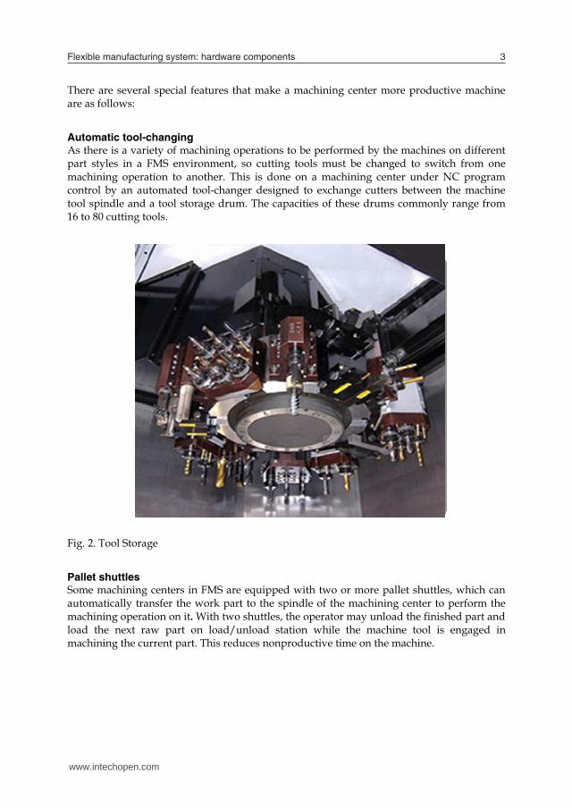
Automatic tool-changing As there is a variety of machining operations to be performed by the machines on different part styles in a FMS environment, so cutting tools must be changed to switch from one machining operation to another. This is done on a machining center under NC program control by an automated tool-changer designed to exchange cutters between the machine tool spindle and a tool storage drum. The capacities of these drums commonly range from 16 to 80 cutting tools.
Fig. 2. Tool Storage
Pallet shuttles Some machining centers in FMS are equipped with two or more pallet shuttles, which can automatically transfer the work part to the spindle of the machining center to perform the machining operation on it. With two shuttles, the operator may unload the finished part and load the next raw part on load/unload station while the machine tool is engaged in machining the current part. This reduces nonproductive time on the machine.
www.intechopen.com
Flexible manufacturing system: hardware components 3
processing and assembly equipments used in a flexible manufacturing system depend upon the type of work being accomplished by the system. In a system designed for machining operations, the principal types of processing stations are CNC machines like CNC machining and turning centers. However, the FMS concept is applicable to various other processes like automated assembly lines, sheet metal fabrication etc.
Machining Stations One of the most common applications of flexible manufacturing system is in the machining operations. The workstations designed in these systems, therefore, predominantly consist of CNC machines tools. The most common CNC machines tools used include CNC machining center, in particular, horizontal machining turning centers. These CNC machine tools possess the features that make them compatible with the FMS. These features include automatic tool changing and storage, use of palletized work parts, etc.
CNC Machining Center A CNC machining center is a highly automated machine tool capable of performing multiple machining operations under CNC control in one setup with minimal human attention. Machining centers generally include automated pallet changers to load the work part to the machine and to unload the finished part that can be readily interfaced with the FMS part handling system. A CNC machining center is a sophisticated CNC machine that can perform milling, drilling, tapping, and boring operations at the same location with a variety of tools.
Fig. 1. CNC Horizontal Machining Center
There are several special features that make a machining center more productive machine are as follows:
Automatic tool-changing As there is a variety of machining operations to be performed by the machines on different part styles in a FMS environment, so cutting tools must be changed to switch from one machining operation to another. This is done on a machining center under NC program control by an automated tool-changer designed to exchange cutters between the machine tool spindle and a tool storage drum. The capacities of these drums commonly range from 16 to 80 cutting tools.
Fig. 2. Tool Storage
Pallet shuttles Some machining centers in FMS are equipped with two or more pallet shuttles, which can automatically transfer the work part to the spindle of the machining center to perform the machining operation on it. With two shuttles, the operator may unload the finished part and load the next raw part on load/unload station while the machine tool is engaged in machining the current part. This reduces nonproductive time on the machine.
www.intechopen.com
Future Manufacturing Systems4
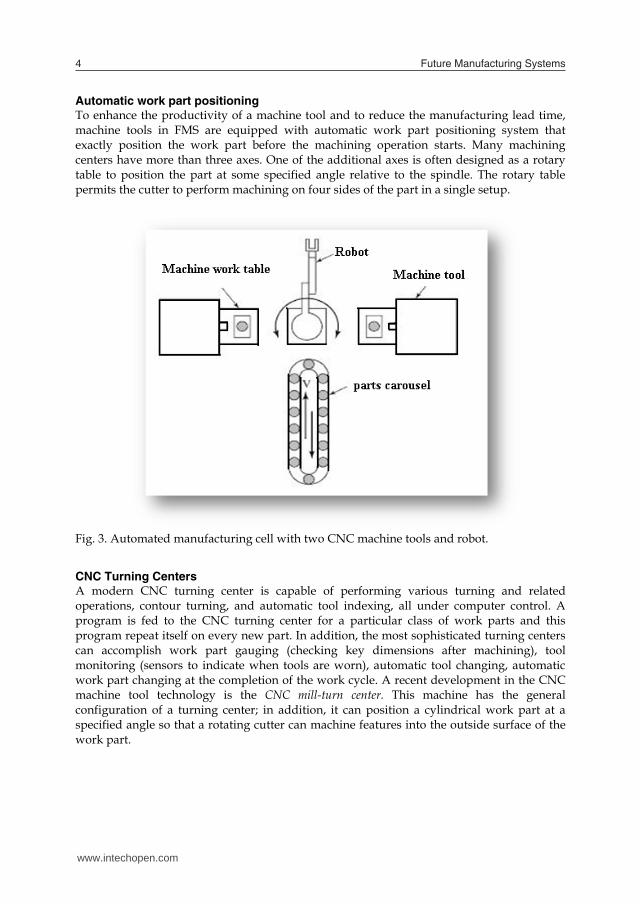
Automatic work part positioning To enhance the productivity of a machine tool and to reduce the manufacturing lead time, machine tools in FMS are equipped with automatic work part positioning system that exactly position the work part before the machining operation starts. Many machining centers have more than three axes. One of the additional axes is often designed as a rotary table to position the part at some specified angle relative to the spindle. The rotary table permits the cutter to perform machining on four sides of the part in a single setup.
Fig. 3. Automated manufacturing cell with two CNC machine tools and robot.
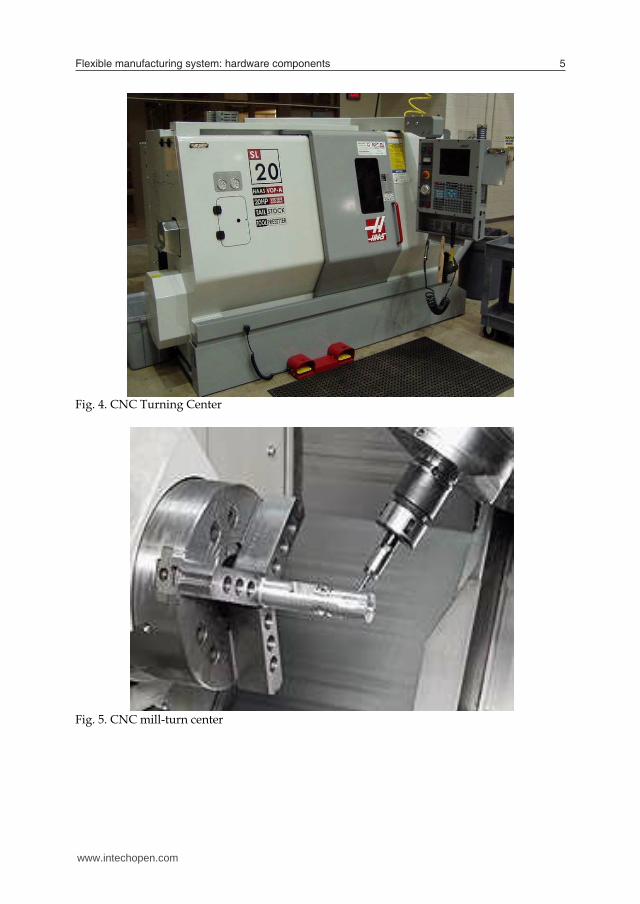
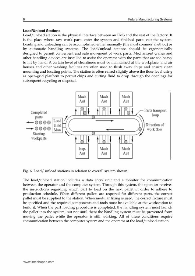
CNC Turning Centers A modern CNC turning center is capable of performing various turning and related operations, contour turning, and automatic tool indexing, all under computer control. A program is fed to the CNC turning center for a particular class of work parts and this program repeat itself on every new part. In addition, the most sophisticated turning centers can accomplish work part gauging (checking key dimensions after machining), tool monitoring (sensors to indicate when tools are worn), automatic tool changing, automatic work part changing at the completion of the work cycle. A recent development in the CNC machine tool technology is the CNC mill-turn center. This machine has the general configuration of a turning center; in addition, it can position a cylindrical work part at a specified angle so that a rotating cutter can machine features into the outside surface of the work part.
Fig. 4. CNC Turning Center
Fig. 5. CNC mill-turn center
www.intechopen.com
Flexible manufacturing system: hardware components 5
Automatic work part positioning To enhance the productivity of a machine tool and to reduce the manufacturing lead time, machine tools in FMS are equipped with automatic work part positioning system that exactly position the work part before the machining operation starts. Many machining centers have more than three axes. One of the additional axes is often designed as a rotary table to position the part at some specified angle relative to the spindle. The rotary table permits the cutter to perform machining on four sides of the part in a single setup.
Fig. 3. Automated manufacturing cell with two CNC machine tools and robot.
CNC Turning Centers A modern CNC turning center is capable of performing various turning and related operations, contour turning, and automatic tool indexing, all under computer control. A program is fed to the CNC turning center for a particular class of work parts and this program repeat itself on every new part. In addition, the most sophisticated turning centers can accomplish work part gauging (checking key dimensions after machining), tool monitoring (sensors to indicate when tools are worn), automatic tool changing, automatic work part changing at the completion of the work cycle. A recent development in the CNC machine tool technology is the CNC mill-turn center. This machine has the general configuration of a turning center; in addition, it can position a cylindrical work part at a specified angle so that a rotating cutter can machine features into the outside surface of the work part.
Fig. 4. CNC Turning Center
Fig. 5. CNC mill-turn center
www.intechopen.com
Future Manufacturing Systems6
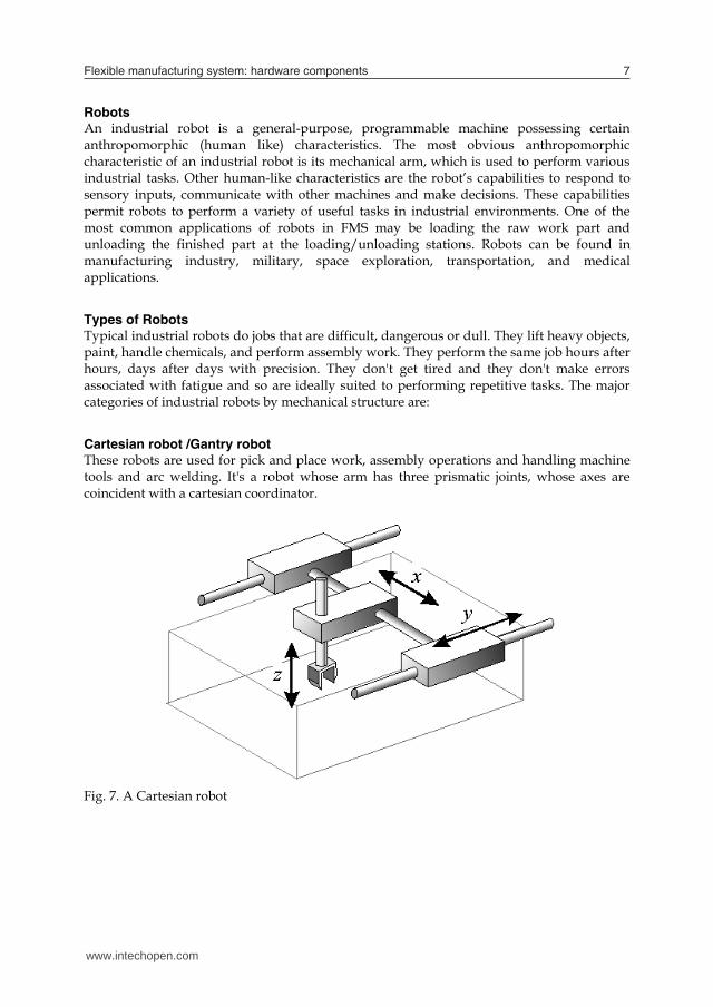
Load/Unload Stations Load/unload station is the physical interface between an FMS and the rest of the factory. It is the place where raw work parts enter the system and finished parts exit the system. Loading and unloading can be accomplished either manually (the most common method) or by automatic handling systems. The load/unload stations should be ergonomically designed to permit convenient and safe movement of work parts. Mechanized cranes and other handling devices are installed to assist the operator with the parts that are too heavy to lift by hand. A certain level of cleanliness must be maintained at the workplace, and air houses and other washing facilities are often used to flush away chips and ensure clean mounting and locating points. The station is often raised slightly above the floor level using as open-grid platform to permit chips and cutting fluid to drop through the openings for subsequent recycling or disposal.
Fig. 6. Load/ unload stations in relation to overall system shown. The load/unload station includes a data entry unit and a monitor for communication between the operator and the computer system. Through this system, the operator receives the instructions regarding which part to load on the next pallet in order to adhere to production schedule. When different pallets are required for different parts, the correct pallet must be supplied to the station. When modular fixing is used, the correct fixture must be specified and the required components and tools must be available at the workstation to build it. When the part loading procedure is completed, the handling system must launch the pallet into the system, but not until then; the handling system must be prevented from moving the pallet while the operator is still working. All of these conditions require communication between the computer system and the operator at the load/unload station.
Robots An industrial robot is a general-purpose, programmable machine possessing certain anthropomorphic (human like) characteristics. The most obvious anthropomorphic characteristic of an industrial robot is its mechanical arm, which is used to perform various industrial tasks. Other human-like characteristics are the robot’s capabilities to respond to sensory inputs, communicate with other machines and make decisions. These capabilities permit robots to perform a variety of useful tasks in industrial environments. One of the most common applications of robots in FMS may be loading the raw work part and unloading the finished part at the loading/unloading stations. Robots can be found in manufacturing industry, military, space exploration, transportation, and medical applications.
Types of Robots Typical industrial robots do jobs that are difficult, dangerous or dull. They lift heavy objects, paint, handle chemicals, and perform assembly work. They perform the same job hours after hours, days after days with precision. They don't get tired and they don't make errors associated with fatigue and so are ideally suited to performing repetitive tasks. The major categories of industrial robots by mechanical structure are:
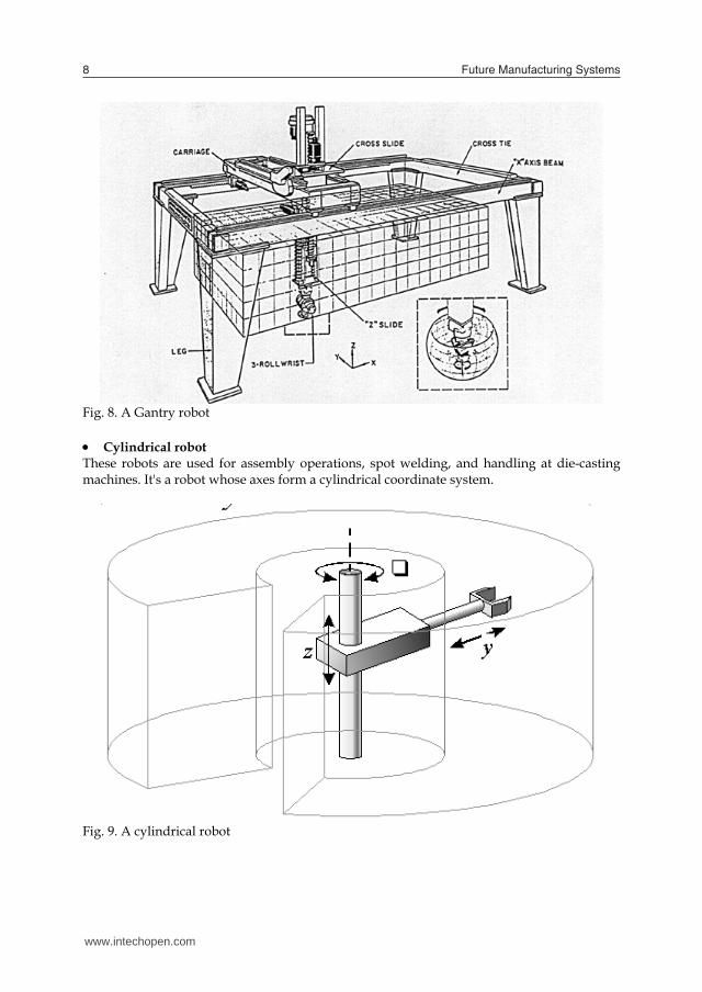
Cartesian robot /Gantry robot These robots are used for pick and place work, assembly operations and handling machine tools and arc welding. It's a robot whose arm has three prismatic joints, whose axes are coincident with a cartesian coordinator.
Fig. 7. A Cartesian robot
www.intechopen.com
Flexible manufacturing system: hardware components 7
Load/Unload Stations Load/unload station is the physical interface between an FMS and the rest of the factory. It is the place where raw work parts enter the system and finished parts exit the system. Loading and unloading can be accomplished either manually (the most common method) or by automatic handling systems. The load/unload stations should be ergonomically designed to permit convenient and safe movement of work parts. Mechanized cranes and other handling devices are installed to assist the operator with the parts that are too heavy to lift by hand. A certain level of cleanliness must be maintained at the workplace, and air houses and other washing facilities are often used to flush away chips and ensure clean mounting and locating points. The station is often raised slightly above the floor level using as open-grid platform to permit chips and cutting fluid to drop through the openings for subsequent recycling or disposal.
Fig. 6. Load/ unload stations in relation to overall system shown. The load/unload station includes a data entry unit and a monitor for communication between the operator and the computer system. Through this system, the operator receives the instructions regarding which part to load on the next pallet in order to adhere to production schedule. When different pallets are required for different parts, the correct pallet must be supplied to the station. When modular fixing is used, the correct fixture must be specified and the required components and tools must be available at the workstation to build it. When the part loading procedure is completed, the handling system must launch the pallet into the system, but not until then; the handling system must be prevented from moving the pallet while the operator is still working. All of these conditions require communication between the computer system and the operator at the load/unload station.
Robots An industrial robot is a general-purpose, programmable machine possessing certain anthropomorphic (human like) characteristics. The most obvious anthropomorphic characteristic of an industrial robot is its mechanical arm, which is used to perform various industrial tasks. Other human-like characteristics are the robot’s capabilities to respond to sensory inputs, communicate with other machines and make decisions. These capabilities permit robots to perform a variety of useful tasks in industrial environments. One of the most common applications of robots in FMS may be loading the raw work part and unloading the finished part at the loading/unloading stations. Robots can be found in manufacturing industry, military, space exploration, transportation, and medical applications.
Types of Robots Typical industrial robots do jobs that are difficult, dangerous or dull. They lift heavy objects, paint, handle chemicals, and perform assembly work. They perform the same job hours after hours, days after days with precision. They don't get tired and they don't make errors associated with fatigue and so are ideally suited to performing repetitive tasks. The major categories of industrial robots by mechanical structure are:
Cartesian robot /Gantry robot These robots are used for pick and place work, assembly operations and handling machine tools and arc welding. It's a robot whose arm has three prismatic joints, whose axes are coincident with a cartesian coordinator.
Fig. 7. A Cartesian robot
www.intechopen.com
Future Manufacturing Systems8
Fig. 8. A Gantry robot Cylindrical robot These robots are used for assembly operations, spot welding, and handling at die-casting machines. It's a robot whose axes form a cylindrical coordinate system.
Fig. 9. A cylindrical robot
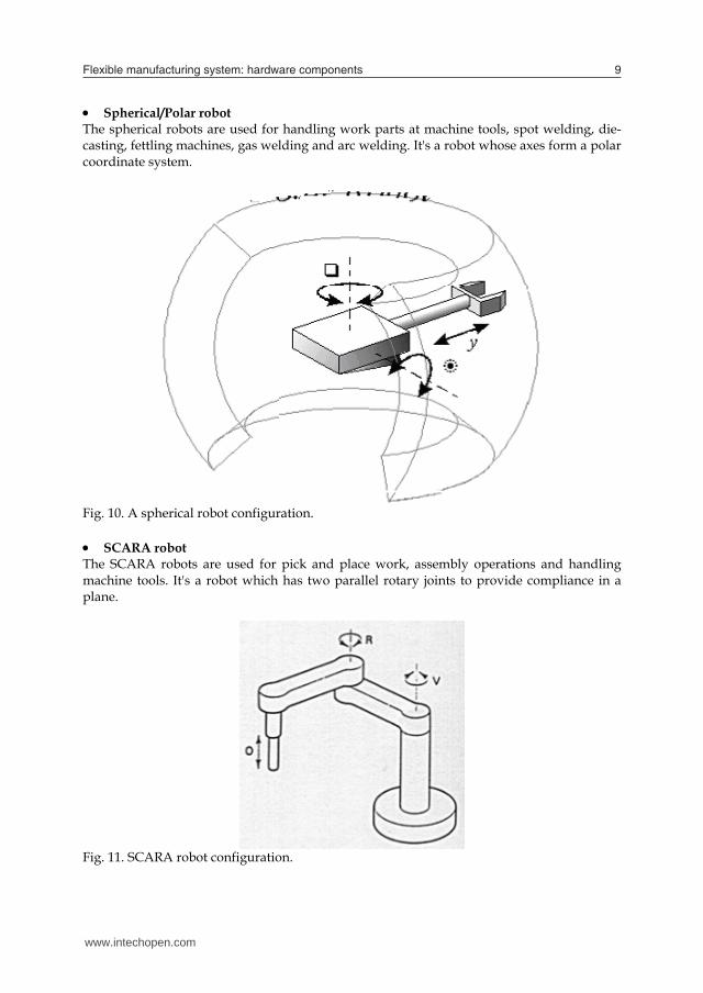
Spherical/Polar robot The spherical robots are used for handling work parts at machine tools, spot welding, die-casting, fettling machines, gas welding and arc welding. It's a robot whose axes form a polar coordinate system.
Fig. 10. A spherical robot configuration. SCARA robot The SCARA robots are used for pick and place work, assembly operations and handling machine tools. It's a robot which has two parallel rotary joints to provide compliance in a plane.
Fig. 11. SCARA robot configuration.
www.intechopen.com
Flexible manufacturing system: hardware components 9
Fig. 8. A Gantry robot Cylindrical robot These robots are used for assembly operations, spot welding, and handling at die-casting machines. It's a robot whose axes form a cylindrical coordinate system.
Fig. 9. A cylindrical robot
Spherical/Polar robot The spherical robots are used for handling work parts at machine tools, spot welding, die-casting, fettling machines, gas welding and arc welding. It's a robot whose axes form a polar coordinate system.
Fig. 10. A spherical robot configuration. SCARA robot The SCARA robots are used for pick and place work, assembly operations and handling machine tools. It's a robot which has two parallel rotary joints to provide compliance in a plane.
Fig. 11. SCARA robot configuration.
www.intechopen.com

Future Manufacturing Systems10
Articulated robot An articulated robot is used for assembly operations, die-casting, fettling machines, gas welding, arc welding and spray painting. It's a robot whose arm has at least three rotary joints.
Fig. 12. Articulated robot configuration
Robot Applications Due to the diverse nature of robots and their flexibility in motion, there are various forms of applications in the flexible manufacturing system. 1. Pick and Drop Operations The most common application of robot within FMS is pick and drop operations, where point to point control devices are sufficient. These applications include tool changing, loading/unloading un-fixtured parts into work tables. The following figure shows a pick and drop robot arm.
2. Contouring Operations A second major application area for robot is in contouring type operations. These include welding, limited machining, deburring, assembly/disassembly and inspection. In case of welding, robots have been proven reliable, effective and efficient. However in other areas such as machining, deburring and inspection robots’ limited accuracy and repeatability limited their applications. In addition, whenever a tool change is required, such as in deburring, the cost of robotic change is almost as expensive as that of three-axis machining center. It is possible that simple operations which require multiple tools are most efficiently performed in the machining centers.
Fig. 13. A robotic arm used for pick and drop operation 3. Assembly/Disassembly The use of robot in FMS is wide spread in assembly and disassembly. Robot have been proven effective for assembly of small parts and printed circuit board (PCB’s). The following figure shows a PCB assembled by robots.
Fig. 14. Printed Circuit Boards (PCB) assembled by robots
www.intechopen.com

Flexible manufacturing system: hardware components 11
Articulated robot An articulated robot is used for assembly operations, die-casting, fettling machines, gas welding, arc welding and spray painting. It's a robot whose arm has at least three rotary joints.
Fig. 12. Articulated robot configuration
Robot Applications Due to the diverse nature of robots and their flexibility in motion, there are various forms of applications in the flexible manufacturing system. 1. Pick and Drop Operations The most common application of robot within FMS is pick and drop operations, where point to point control devices are sufficient. These applications include tool changing, loading/unloading un-fixtured parts into work tables. The following figure shows a pick and drop robot arm.
2. Contouring Operations A second major application area for robot is in contouring type operations. These include welding, limited machining, deburring, assembly/disassembly and inspection. In case of welding, robots have been proven reliable, effective and efficient. However in other areas such as machining, deburring and inspection robots’ limited accuracy and repeatability limited their applications. In addition, whenever a tool change is required, such as in deburring, the cost of robotic change is almost as expensive as that of three-axis machining center. It is possible that simple operations which require multiple tools are most efficiently performed in the machining centers.
Fig. 13. A robotic arm used for pick and drop operation 3. Assembly/Disassembly The use of robot in FMS is wide spread in assembly and disassembly. Robot have been proven effective for assembly of small parts and printed circuit board (PCB’s). The following figure shows a PCB assembled by robots.
Fig. 14. Printed Circuit Boards (PCB) assembled by robots
www.intechopen.com

Future Manufacturing Systems12
Inspection Equipments Since an FMS is a closed system (feedback control system), it is necessary to provide some means to monitor the quality of operations being performed. This monitoring can take place in many different places and by different components.
Fig. 15. Multi Function Gantry CMM
Fig. 16. Coordinate measuring machine
1. Coordinate Measuring Machine The most obvious type of inspection equipments is coordinate measuring machine (CMM). This machine can be programmed to probe a piece part and identify depth of holes, flatness of surfaces and perpendicularity.
Fig. 17. A Large Scale CMM Special requirements usually include constant temperature congruity environment and piece part. Also, because of the slow movements necessary to precisely measure surfaces, the inspection time is usually long compared to machining time. 2. Probing Machining Centers Probe marching centers are also used as for inspection purposes in addition to CMM station. These machines inspect equipment in work centers by inserting a probe into the gripper or spindle and then moving the probe contacting the work piece or fixture.
www.intechopen.com

Flexible manufacturing system: hardware components 13
Inspection Equipments Since an FMS is a closed system (feedback control system), it is necessary to provide some means to monitor the quality of operations being performed. This monitoring can take place in many different places and by different components.
Fig. 15. Multi Function Gantry CMM
Fig. 16. Coordinate measuring machine
1. Coordinate Measuring Machine The most obvious type of inspection equipments is coordinate measuring machine (CMM). This machine can be programmed to probe a piece part and identify depth of holes, flatness of surfaces and perpendicularity.
Fig. 17. A Large Scale CMM Special requirements usually include constant temperature congruity environment and piece part. Also, because of the slow movements necessary to precisely measure surfaces, the inspection time is usually long compared to machining time. 2. Probing Machining Centers Probe marching centers are also used as for inspection purposes in addition to CMM station. These machines inspect equipment in work centers by inserting a probe into the gripper or spindle and then moving the probe contacting the work piece or fixture.
www.intechopen.com

Future Manufacturing Systems14
Fig. 18. Example of on-machine checking and inspection Programmable Logic Controllers (PLC’s): A programmable logic controller (PLC) is a microcomputer-based controller that uses stored instructions in programmable memory to implement logic, sequencing, timing, counting, and arithmetic functions through digital or analog input/output (I/O) module, for controlling machines and processes. PLC is universally called ‘Work Horse’ of industrial automations. Various systems like material handling system, material storage system, load/unloading stations, etc. are programmed through PLC in order to streamline the operations in a flexible manufacturing system.:
PLCs consist of input modules or points, a central processing unit (CPU), and output modules or points. The basic components of PLC are the followings:
Processor Memory unit Power supply I/O module Programming device
These components are housed in a suitable cabinet for the industrial environment. The processor is the central processing unit of the programmable controller. It execute various logic and sequencing functions by operating on the PLC input to determine the appropriate output signal. Connected to the CPU is the PLC memory unit, which contains the programs of logic, sequencing, and I/O operation. It also holds data files associated with these programs including I/O status bits, counter and timer constants, and other type variable and parameter values. This memory unit is referred to as the user or applicant memory because its contents are entered by the user. A power supply is typically used to drive a PLC. The I/O module provides the connections to the industrial equipments or process that is to be controlled. Inputs to the controller are signals from limits switches, push buttons,
sensors, and other on/off devices. Outputs from the controller are on/off signals to operate motors, valves and other devices required to actuate the process. The PLC is programmed by means of a programming device. The programming device is usually detachable from the PLC cabinet so that it can be shared among different controllers. The following figure shows a PLC input/ output module.
Fig. 19. PLC Input /Output Module
References
1. Mikell P. Groover, “Automation, Production Systems and Computer Integrated Manufacturing”, 3rd Edition, Pearson Education, Inc., 2008.
2. Implementing Flexible Manufacturing Systems by Greenwood, Nigel. Published by M Macmillan Education. 1988
3. Flexible manufacturing system (FMS): the investigative phase By David L. Setter, Published by Technical Communications, Kansas City Division, Allied-Signal Aerospace, 1993
4. Flexible Manufacturing Systems: Decision Support for Design and Operation" H. Tempelmeier and H. Kuhn John Wiley and Sons 1993
5. Production and Operations Management, By Chary 6. Rapid prototyping: theory and practice, By Ali K. Kamrani, Emad Abouel Nasr 7. http://www.robots.com
www.intechopen.com

Flexible manufacturing system: hardware components 15
Fig. 18. Example of on-machine checking and inspection Programmable Logic Controllers (PLC’s): A programmable logic controller (PLC) is a microcomputer-based controller that uses stored instructions in programmable memory to implement logic, sequencing, timing, counting, and arithmetic functions through digital or analog input/output (I/O) module, for controlling machines and processes. PLC is universally called ‘Work Horse’ of industrial automations. Various systems like material handling system, material storage system, load/unloading stations, etc. are programmed through PLC in order to streamline the operations in a flexible manufacturing system.:
PLCs consist of input modules or points, a central processing unit (CPU), and output modules or points. The basic components of PLC are the followings:
Processor Memory unit Power supply I/O module Programming device
These components are housed in a suitable cabinet for the industrial environment. The processor is the central processing unit of the programmable controller. It execute various logic and sequencing functions by operating on the PLC input to determine the appropriate output signal. Connected to the CPU is the PLC memory unit, which contains the programs of logic, sequencing, and I/O operation. It also holds data files associated with these programs including I/O status bits, counter and timer constants, and other type variable and parameter values. This memory unit is referred to as the user or applicant memory because its contents are entered by the user. A power supply is typically used to drive a PLC. The I/O module provides the connections to the industrial equipments or process that is to be controlled. Inputs to the controller are signals from limits switches, push buttons,
sensors, and other on/off devices. Outputs from the controller are on/off signals to operate motors, valves and other devices required to actuate the process. The PLC is programmed by means of a programming device. The programming device is usually detachable from the PLC cabinet so that it can be shared among different controllers. The following figure shows a PLC input/ output module.
Fig. 19. PLC Input /Output Module
References
1. Mikell P. Groover, “Automation, Production Systems and Computer Integrated Manufacturing”, 3rd Edition, Pearson Education, Inc., 2008.
2. Implementing Flexible Manufacturing Systems by Greenwood, Nigel. Published by M Macmillan Education. 1988
3. Flexible manufacturing system (FMS): the investigative phase By David L. Setter, Published by Technical Communications, Kansas City Division, Allied-Signal Aerospace, 1993
4. Flexible Manufacturing Systems: Decision Support for Design and Operation" H. Tempelmeier and H. Kuhn John Wiley and Sons 1993
5. Production and Operations Management, By Chary 6. Rapid prototyping: theory and practice, By Ali K. Kamrani, Emad Abouel Nasr 7. http://www.robots.com
www.intechopen.com

Future Manufacturing Systems16
www.intechopen.com

Future Manufacturing SystemsEdited by Tauseef Aized
ISBN 978-953-307-128-2Hard cover, 268 pagesPublisher SciyoPublished online 17, August, 2010Published in print edition August, 2010
InTech EuropeUniversity Campus STeP Ri Slavka Krautzeka 83/A 51000 Rijeka, Croatia Phone: +385 (51) 770 447 Fax: +385 (51) 686 166www.intechopen.com
InTech ChinaUnit 405, Office Block, Hotel Equatorial Shanghai No.65, Yan An Road (West), Shanghai, 200040, China
Phone: +86-21-62489820 Fax: +86-21-62489821
This book is a collection of articles aimed at finding new ways of manufacturing systems developments. Thearticles included in this volume comprise of current and new directions of manufacturing systems which Ibelieve can lead to the development of more comprehensive and efficient future manufacturing systems.People from diverse background like academia, industry, research and others can take advantage of thisvolume and can shape future directions of manufacturing systems.
How to referenceIn order to correctly reference this scholarly work, feel free to copy and paste the following:
Tauseef Aized (2010). Flexible Manufacturing System: Hardware Requirements, Future ManufacturingSystems, Tauseef Aized (Ed.), ISBN: 978-953-307-128-2, InTech, Available from:http://www.intechopen.com/books/future-manufacturing-systems/flexible-manufacturing-system-hardware-requirements