DR 4.3: Communication and knowledge ow gluing the multi ... · DR 4.3:Communication and knowledge...
36
DR 4.3: Communication and knowledge flow gluing the multi-robot collaborative framework Luigi Freda * , Mario Gianni * , Fiora Pirri * * Alcor Laboratory, Department of Computer, Control, and Management Engineer- ing “Antonio Ruberti” - Sapienza University of Rome. h[email protected]i Project, project Id: EU FP7 TRADR / ICT-60963 Project start date: Nov 1 2013 (50 months) Due date of deliverable: M38 Actual submission date: February 2016 Lead partner: ROMA Revision: final Dissemination level: PU This document describes the progress status of the research work of WP4 in Year 3 of TRADR project. WP4 developed a framework for both multi-robot path planning and patrolling. The underlying inter-robot communication flow is leveraged by a distributed hybrid communication model. Persistence has also been taken into account within the functional archi- tecture of the framework, in terms of access and reuse of both maps and robot trajectories of previous sorties. The document reports both the research and engineering work that has been performed, in collaboration with other project partners, to effectively deploy a team of UGVs in real scenarios under the control of the developed framework. Moreover, a virtual simulated environment of the TRADR system is de- scribed. It has been used during testing and validation, before real deploy- ment. 1
Transcript of DR 4.3: Communication and knowledge ow gluing the multi ... · DR 4.3:Communication and knowledge...
DR 4.3: Communication and knowledge flow gluing
the multi-robot collaborative framework
Luigi Freda∗, Mario Gianni∗, Fiora Pirri∗
∗Alcor Laboratory, Department of Computer, Control, and Management Engineer-
ing “Antonio Ruberti” - Sapienza University of Rome.
Project, project Id: EU FP7 TRADR / ICT-60963Project start date: Nov 1 2013 (50 months)Due date of deliverable: M38Actual submission date: February 2016Lead partner: ROMARevision: finalDissemination level: PU
This document describes the progress status of the research work of WP4 inYear 3 of TRADR project.
WP4 developed a framework for both multi-robot path planning andpatrolling. The underlying inter-robot communication flow is leveraged bya distributed hybrid communication model.
Persistence has also been taken into account within the functional archi-tecture of the framework, in terms of access and reuse of both maps androbot trajectories of previous sorties.
The document reports both the research and engineering work that hasbeen performed, in collaboration with other project partners, to effectivelydeploy a team of UGVs in real scenarios under the control of the developedframework.
Moreover, a virtual simulated environment of the TRADR system is de-scribed. It has been used during testing and validation, before real deploy-ment.
1

DR 4.3:Communication and knowledge flow gluing the multi-robot collaborative framework Freda et al.
The document is organized as follows. Planned work is introduced andthe actual work is discussed, highlighting the relevant achievements, howthese contribute to the current state of the art and to the aims of the project.
EU FP7 TRADR (ICT-60963) 2

DR 4.3:Communication and knowledge flow gluing the multi-robot collaborative framework Freda et al.
1 Tasks, objectives, results 61.1 Planned work . . . . . . . . . . . . . . . . . . . . . . . . . . . . . . . . . . . 61.2 Addressing reviewers’ comments . . . . . . . . . . . . . . . . . . . . . . . . 71.3 Actual work performed . . . . . . . . . . . . . . . . . . . . . . . . . . . . . . 10
1.3.1 Multi-robot path planning and patrolling . . . . . . . . . . . . . . . 101.3.2 Software Development and Release . . . . . . . . . . . . . . . . . . . 13
1.4 Relation to the state-of-the-art . . . . . . . . . . . . . . . . . . . . . . . . . 141.4.1 Multi-robot patrolling . . . . . . . . . . . . . . . . . . . . . . . . . . 14
2 Annexes 202.1 Freda (2017), “3D Multi-Robot Patrolling with a Two-Level Coordination
Strategy: Simulations and Experiments” . . . . . . . . . . . . . . . . . . . . 202.2 Wiki-MR-Use-Cases (2017), “Multi-Robot Use Cases Wiki page on Redmine” 212.3 Wiki-VREP (2017), “V-REP Simulation Wiki page on Redmine” . . . . . . 212.4 Wiki-MR (2017), “Multi-Robot Path Planning and Patrolling Wiki page
on Redmine” . . . . . . . . . . . . . . . . . . . . . . . . . . . . . . . . . . . 22
A Multi-Robot Use Cases Wiki page on Redmine 23
B V-REP Simulation Wiki page on Redmine 24
C Multi-Robot Path Planning and Patrolling Wiki page on Redmine 25
EU FP7 TRADR (ICT-60963) 3

DR 4.3:Communication and knowledge flow gluing the multi-robot collaborative framework Freda et al.
Executive Summary
This report describes the research work of WP4 toward the developmentof the formal methods needed in TRADR to model knowledge exchange,knowledge maintenance, information sharing, common and individual deci-sion structures in order to enable collaborative planning.
In Year 3 we developed a functional architecture allowing for the de-ployment of a team of TRADR UGVs in real scenarios. This architecturemanages the communication, the coordination and the collaboration amongthe UGVs in both multi-robot path planning and patrolling tasks (see Sub-section 1.3.1, Section 1.3).
More precisely, the architecture integrates two levels of coordinationto handle with both interferences and spatial conflicts among the UGVs,namely, the topological and the metric level.
At the topological level, each robot selects its target node on a topologicalmap, relying on a shared heuristic criterion as well as on a coordinationmechanism so as to prevent topological conflicts (e.g., such as same targetnode selection).
At the metric level, each robot path planner manages and minimizesthe occurrences of spatial conflicts according to a multi-robot traversabilityfunction spanning over a metric representation of space (ETHZ).
The functional architecture has been fully distributed over nimbro network,an inherently fault-tolerant network transport solution for multi-master ROSsystems (Fraunhofer). A hybrid communication model over this networkleverages the inter-robot communication flow.
Concerning persistence, the architecture re-uses maps and robot trajec-tory histories retrieved from previous sorties for traversability analysis andtopological mapping, respectively.
An implementation of the above architecture for nimbro has been re-leased under two versions. The first version allows for the deployment ofthe TRADR system in virtual simulation. The second enables both multi-robot path planning and patrolling of a team of UGVs interconnected viathe TRADR Core for real deployment.
Logs of the software development process as well as documentation andguidelines about the usage of the code are available on the channels used bythe TRADR project (see Subsection 1.3.2, Section 1.3).
The research work on environment representation and storage has beendone in collaboration with ETHZ. Fraunhofer supported us first in the de-ployment of the functional architecture over nimbro and then in the dis-tribution over the TRADR Core. CTU together with Fraunhofer managedthe upgrade of the robot network and of the new device that will provideon-demand restarting of the laser motor.
EU FP7 TRADR (ICT-60963) 4
DR 4.3:Communication and knowledge flow gluing the multi-robot collaborative framework Freda et al.
Role of Communication and knowledge flow gluingthe multi-robot collaborative framework in TRADR
The work performed in Year 3 by WP4 contributes to the overall objectiveof TRADR project by providing a fully integrated ready-to-use frameworkfor deploying a team of UGVs to patrol a set of interesting areas either givenas input by end-users (via a suitable GUI) or built upon robot trajectoriescollected during previous sorties (see Subsection 1.3.1, Section 1.3).
WP4 also provided the consortium with a version of the above frameworkwhich allows any user to run the TRADR system, under nimbro network,in virtual simulation, as benchmark (see Subsection 1.3.2, Section 1.3).
Persistence
WP4 addressed persistence in Year 3 by developing two communicationprotocols under the nimbro network infrastructure to save/load onto/fromthe TRADR Core (i) the maps of the environments explored by the UGVsduring previous sorties and (ii) the trajectories followed by the robots duringthese exploration phases. This information is used to refine the estimationof the normals for both traversability assessment and path planning. It isalso used to build an estimate of the topology of the areas to be patrolled.Patrol graphs are further stored onto the TRADR Core to be used in nextsorties. Here, ETHZ managed the server side of the map saver. ROMAdeveloped both the client side of the map service and the service for robottrajectory saving. Frauhnofer contributed to the integration of the abovework with nimbro and the TRADR Core.
Contribution to the TRADR scenarios and proto-types
The research work of WP4 contributes to Year 3 Use-cases as documentedon the related wiki page on Redmine (https://redmine.ciirc.cvut.cz/projects/tradr/wiki/Scenario_and_use_cases_Year_3) and also describedin Deliverable DR.7.3. Details are reported in Table 1
Use-cases in Table 1 have been accommodated on the basis of the doc-ument in Annex 2.2. Annex 2.2 collects useful information for the identi-fication of interesting multi-robot tasks within the TRADR project. Theobjective of this document is two-fold: (1) to clearly define a set of doabletasks which will be actually implemented for the reviews and demos and(2) to foster collaboration and discussions within the TRADR team. Anexcerpt of the main content of Annex 2.2 in terms of multi-robot use-cases is given in Table 2. Additional details are also available at https:
EU FP7 TRADR (ICT-60963) 5

DR 4.3:Communication and knowledge flow gluing the multi-robot collaborative framework Freda et al.
N. Description Realization Partners
7
The robot should be able to plan basedon a map generated during a previous sortie(map should be obtained by merging two mapsoffline).
Robot collects map during 1st sortieand uses it in subsequent sortieRobots start at same locationor use a tool to rigidly merge maps.
ETHZ, ROMA
8Dynamic environment (among sorties)poses challenge for map creation.
During subsequent sortie somethingin the environment has changed.
CTU, ETHZ, ROMA
12 Mulit-robot Patrolling
Robots visit the nodes of a topologicalgraph representation of the environment.These nodes can be also given as inputby the user.
ROMA
Table 1: Contributions of WP4 to Year 3 Use-cases of TRADR.
ID. Description
PCPSE1 The environment map is already available and given as input to the robots.
PCPSE2 The robots are able to continuously localize themselves w.r.t. the given map.
PCPSE4 Robots are able to continuously communicate and exchange their positions and relevant data.
PCPSE9 Dynamic mapping (at least considering robot occlusions)
Table 2: Table of requirements for multi-robot uses-cases.
//redmine.ciirc.cvut.cz/projects/tradr/wiki/PCPSE.
EU FP7 TRADR (ICT-60963) 6
DR 4.3:Communication and knowledge flow gluing the multi-robot collaborative framework Freda et al.
1 Tasks, objectives, results
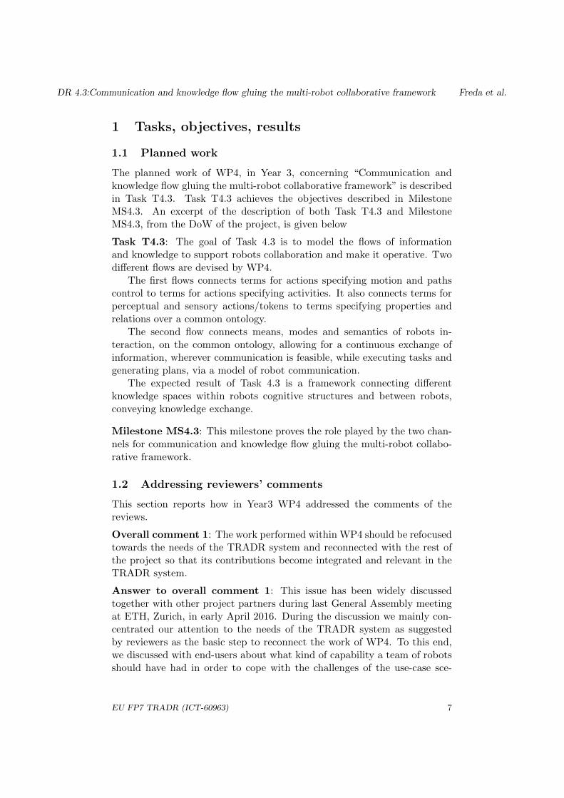
1.1 Planned work
The planned work of WP4, in Year 3, concerning “Communication andknowledge flow gluing the multi-robot collaborative framework” is describedin Task T4.3. Task T4.3 achieves the objectives described in MilestoneMS4.3. An excerpt of the description of both Task T4.3 and MilestoneMS4.3, from the DoW of the project, is given below
Task T4.3: The goal of Task 4.3 is to model the flows of informationand knowledge to support robots collaboration and make it operative. Twodifferent flows are devised by WP4.
The first flows connects terms for actions specifying motion and pathscontrol to terms for actions specifying activities. It also connects terms forperceptual and sensory actions/tokens to terms specifying properties andrelations over a common ontology.
The second flow connects means, modes and semantics of robots in-teraction, on the common ontology, allowing for a continuous exchange ofinformation, wherever communication is feasible, while executing tasks andgenerating plans, via a model of robot communication.
The expected result of Task 4.3 is a framework connecting differentknowledge spaces within robots cognitive structures and between robots,conveying knowledge exchange.
Milestone MS4.3: This milestone proves the role played by the two chan-nels for communication and knowledge flow gluing the multi-robot collabo-rative framework.
1.2 Addressing reviewers’ comments
This section reports how in Year3 WP4 addressed the comments of thereviews.
Overall comment 1: The work performed within WP4 should be refocusedtowards the needs of the TRADR system and reconnected with the rest ofthe project so that its contributions become integrated and relevant in theTRADR system.
Answer to overall comment 1: This issue has been widely discussedtogether with other project partners during last General Assembly meetingat ETH, Zurich, in early April 2016. During the discussion we mainly con-centrated our attention to the needs of the TRADR system as suggestedby reviewers as the basic step to reconnect the work of WP4. To this end,we discussed with end-users about what kind of capability a team of robotsshould have had in order to cope with the challenges of the use-case sce-
EU FP7 TRADR (ICT-60963) 7

DR 4.3:Communication and knowledge flow gluing the multi-robot collaborative framework Freda et al.
nario in Year 3. Among several feasible alternatives, the end-users came upwith the need to have functionality to instruct a team of UGVs to regu-larly visit certain areas of interest, detected across previous sorties. Aftera preliminary study of the problem in the context of the Year 3 use-cases,we identified the main building blocks of the functional architecture neededto develop the above functionality as well as to make it operative in theTRADR project. In the next months, we arranged several meeting with in-dividual partners, beside those already scheduled into the project roadmap,to integrate their research work. This effort involved ETHZ for mapping,ROMA for path-planning and traversability analysis, Fraunhofer for nimbroand the TRADR Core. We also improved the framework for virtual simu-lation, developed in Year 2, to test a prototype of the integrated functionalarchitecture for multi-robot path planning and patrolling. We arranged dur-ing the TRADR evaluation meeting in Dortmund, Germany, last November2016, several sessions in which the end-users have been trained to use insimulation the developed functionality. We improved the usability of theGUI according to the end-user insights gathered during this training ses-sion. We finally tested both the multi-robot path-planning and patrollingwith two UGVs in real scenarios, resembling small-scale disaster situations,under nimbro and the TRADR Core (see Section 1.3).
Overall comment 2: In WP4, the work reported in the deliverable D4.2and orally presented to the reviewers in the 1st day of the Y2 review meetingappeared quite disconnected with the standalone demonstration presentedin the 2nd day of the review meeting.
Answer to overall comment 2: This is definitely true, although fewreferences about the framework for virtual simulation as well as the contentof the standalone demonstration have been given in Deliverable DR.4.2 andin the oral presentation, respectively. However, we recovered form such adiscrepancy in Year 3.
Overall comment 3: Also, the contributions from other partners thanROME to this WP are not clearly visible.
Answer to overall comment 3: In Year 3 we have taken care of thatand the contribution of the other project partners is clearly much morevisible. In particular, ETHZ contributed to integrate mapping, Fraunhofersupported the integration with nimbro and with the TRADR Core. CTUprovided support to upgrade the robot hardware (see Section 1.3).
Overall comment 4: Moreover, being persistent models for multi-robotacting a key scientific objective of the TRADR project, after two years of theproject development, the theoretical multi-robot collaboration frameworkbased on relational structures and tensor formulation presented in the 1stday has not been integrated in the TRADR system, nor demonstrated withdata from either simulation or real robots yet. The consortium must address
EU FP7 TRADR (ICT-60963) 8

DR 4.3:Communication and knowledge flow gluing the multi-robot collaborative framework Freda et al.
this issue as soon as possible and put in practice a contingency plan duringY3, so that it does not become a serious threat to the projects success andthe aforementioned projects scientific objective can be timely accomplished.
Answer to overall comment 4: After a discussion with other projectpartners we decided to activate a contingency plan. The main objectiveof this plan was to establish even more closer synergies with the others infavor of a framework which allows for real deployment of a team of UGVsfor patrolling areas of interest (see Section 1.3).
Specific comment 1: In Y2, the research team demonstrated an overallacceptable progress in WP4 but the integration of the main parts in theTRADR system is unclear and not convincing yet.
Answer to specific comment 1: Considerable amount of work has beendevoted by WP4 in Year 3 to integration in order to address this issue (seeSubsection 1.3.2, Section 1.3).
Specific comment 2: Moreover, the contributions from other partnersthan ROME are not sufficiently visible.
Answer to specific comment 2: The work reported in this document aswell as the content of the demonstration that we are going to present at thereviews very well describe the contributions of the other project partners inWP4 (see Section 1.3).
Specific comment 3: Despite being promising, the theoretical multi-robotcollaboration framework was not visible in the integrated demonstration,even in the V-REP simulation environment presented in the standalonedemonstration, and has not been published yet in a scientific venue.
Answer to specific comment 3: This research work has not been pub-lished yet. On the basis of the status of this research we have chosen topostpone the integration of this part of the work in TRADR.
Specific comment 4: Instead and surprisingly, the standalone demon-stration showed in a simulation heterogeneous robots doing a coordinatedmulti-robot coverage task that adapts the heuristic of the real-time A* nav-igation algorithm to do a persistent search (the heuristic tends to directrobots to less visited nodes).
Answer to specific comment 4: This work has been the result of ROMAresearch efforts after the delivery of Deluverable DR.4.2 and before the Year2 review meeting. That’s why it has not been reported in DR.4.2 but hasbeen shown at the review. We are sorry for such a discrepancy.
Specific comment 5: Also surprisingly, this coverage approach neither wasreported in deliverable D4.2 nor presented orally to reviewers in the work-package presentations held during the first day of the review meeting. It isnot clear whether it is meant to be a contribution or merely a demonstration
EU FP7 TRADR (ICT-60963) 9
DR 4.3:Communication and knowledge flow gluing the multi-robot collaborative framework Freda et al.
of collaborative path planning and plan execution.
Answer to specific comment 5: This comment is partially true. Duringthe oral presentation few slides have been shown to the reviewers describingthe demonstration in virtual simulation of a team of heterogeneous robotscovering an environment. A video also accompanied this part of the presen-tation.
Specific comment 6: As only simulation experiments have been donein Y2, the chosen trade-off between simulation and experiments with realdata, either from datasets of past exercises of the TRADR system or fromintegration and experiments with the TRADR system, was not appropriateto validate the theoretical framework also in real scenarios and make it avisible and relevant asset to the projects integrated demonstrator as it shouldbe. Indeed, it did not seem that data at least from simulation was used todemonstrate the empirical usefulness of the collaboration framework.
Answer to specific comment 6: We agree. Thanks for this note. We aredealing with this issue.
Specific comment 7: As the proposed framework requires considerableamounts of past data to become effective and requires eventually many sor-ties, the research team should also consider a technique that can tackle themission with a shorter past history, i.e. during the first sorties of the mission.Using data from human- robot collaboration developed in WP5 can be animportant source of test data to further develop and refine the framework.
Answer to specific comment 7: Many thanks for this suggestion. Weare actually also considering this mode in our research.
Specific comment 8: The work progress in WP4 appears quite discon-nected with the rest of the project and its contribution to the TRADRintegrated system (i.e. simulator, scenarios, system integration) is unclearand not sufficiently visible. A contingency plan must be devised by allpartners involved in WP4, in order to refocus the work that needs to bedone throughout Y3, not only to compensate this divergence with respectthe projects DoW, but also to make explicit and relevant the contributionof WP4 to the TRADR system used by the consortium in future joint ex-ercises and evaluation exercises. The importance of this contribution onmulti-robot collaboration will also be crucial in Y3 and in Y4 because mis-sions will involve necessarily multiple and heterogeneous robots working incollaboration.
Answer to specific comment 8: We followed the suggestion of the re-viewers. Indeed we actuated a contingency plan that, although it deviatedfor the work as planned in the DoW, bridged the gap between the contri-bution of WP4 to the TRADR system and the contribution of the otherproject partners to WP4 (see Subsection 1.3.2, Section 1.3).
EU FP7 TRADR (ICT-60963) 10

DR 4.3:Communication and knowledge flow gluing the multi-robot collaborative framework Freda et al.
Specific comment 9: Also the reported publication outcomes of WP 4 arebelow the average of other WPs.
Answer to specific comment 9: Many works are under submission. Sowe hope to bridge also this gap very soon.
1.3 Actual work performed
This section describes the research work of WP4 in Year 3 of TRADRproject. It is organized as follows. Next subsection introduces the multi-robot path planning and patrolling. Subsection 1.3.2 refers to software doc-umentation history, installation instructions and user manuals of the relatedcode. Wiki pages for this have been set up and maintained. They are avail-able to all the project partners. More details can be found in Annex 2.3 andin Annex 2.4.
1.3.1 Multi-robot path planning and patrolling
This subsection is organized as follows. Next paragraph introduces the func-tional architecture. Paragraph 1.3.1.3 describes the two-level coordinationstrategy. Paragraph 1.3.1.4 presents the two different procedures for pa-trolling graph building. Paragraph 1.3.1.5 briefly introduce the 3D GUIdesigned for end-user interaction purposes. Paragraph 1.3.1.6 describes thecommunication model. Finally experimental results in Paragraph 1.3.1.7.More details can be found in Annex 2.1.
1.3.1.1 The Functional Architecture
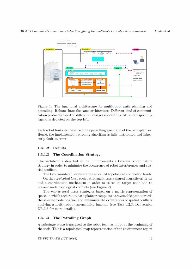
The functional architecture for the real deployment of a team of UGVs isdepicted in Fig. 1. The main blocks are listed below.
• The robots (each one with its own ID ∈ 1, ..., N): these host the on-board functionalities which concern decision and processing aspectsboth at topological level and at metric level (depicted in Fig. 1 as sub-blocks). Laser mapping, segmentation and traversability analysis areat the bottom of the metric level pipeline [25, 17, 18, 21, 20].
• The core services hosted in the TRADR core: these represent themulti-robot system persistence and provide crucial services which allowthe various modules to load and save map, trajectories and patrollinggraphs.
• The core modules hosted in the TRADR core: these include the pa-trolling graph builder and the patrolling monitor.
• The multi-robot 3D GUI.
EU FP7 TRADR (ICT-60963) 11
DR 4.3:Communication and knowledge flow gluing the multi-robot collaborative framework Freda et al.
Figure 1: The functional architecture for multi-robot path planning andpatrolling. Robots share the same architecture. Different kind of communi-cation protocols based on different messages are established: a correspondinglegend is depicted on the top left.
Each robot hosts its instance of the patrolling agent and of the path-planner.Hence, the implemented patrolling algorithm is fully distributed and inher-ently fault-tolerant.
1.3.1.2 Results
1.3.1.3 The Coordination Strategy
The architecture depicted in Fig. 1 implements a two-level coordinationstrategy in order to minimize the occurrence of robot interferences and spa-tial conflicts.
The two considered levels are the so called topological and metric levels.On the topological level, each patrol agent uses a shared heuristic criterion
and a coordination mechanism in order to select its target node and toprevent node topological conflicts (see Figure 2).
The metric level hosts strategies based on a metric representation ofspace, in which each robot path planner computes a traversable path towardsthe selected node position and minimizes the occurrences of spatial conflictsapplying a multi-robot traversability function (see Task T2.3, DeliverableDR.2.3 for more details).
1.3.1.4 The Patrolling Graph
A patrolling graph is assigned to the robot team as input at the beginning ofthe task. This is a topological map representation of the environment region
EU FP7 TRADR (ICT-60963) 12

DR 4.3:Communication and knowledge flow gluing the multi-robot collaborative framework Freda et al.
(a) (b)
Figure 2: RVIZ Visualization (see Paragraph 1.3.1.5, Subsection 1.3.1) ofa team of TRADR UGVs (2a) negotiating paths along a corridor and (2b)coordinating their planning strategy in a critical case. Point clouds arecolored on the basis of the approach for traversability assessment describedin [25, 17, 18]; yellow spots connected to straight lines of the same colordenote nodes of the patrolling graph
the robots have to patrol. In this graph, a node represents an interesting 3Dlocation to visit while an edge between two nodes represents the existenceof a traversable path between the two corresponding locations.
The patrolling graph can be defined by the user or from robot trajectoriescollected during past sorties.
In the first mode the user is provided with a 3D GUI. This GUI allowsthe user to load a saved map and to interactively build a patrolling graphon the corresponding traversable map (see Task T2.3, Deliverable DR.2.3for more details).
In the second mode we resort to the approach similar to that describedin [25] to estimate a potential patrolling graph in the form of an undirectedgraph from the trajectories followed by each robot during a past sortie,
1.3.1.5 3D Interface: RVIZ data visualization and commands
The 3D GUI allows to visualize the distinct robot maps and the distinctrobot modules in the same main /map frame. This is possible since, in eachrobot, we added an intermediate /robot name/map frame between the main/map frame and the /odom frame and we remapped each robot link frameby adding /robot name prefix (more details can be found in Task T6.3,Deliverable DR.6.3).
EU FP7 TRADR (ICT-60963) 13

DR 4.3:Communication and knowledge flow gluing the multi-robot collaborative framework Freda et al.
(a) (b)
Figure 3: (3a) A team of TRADR UGVs deployed in virtual simulation (V-REP [14]) over nimbro and the TRADR Core; (3b) RVIZ Visualization (seeParagraph 1.3.1.5, Subsection 1.3.1) of scenario in Figure 3a.
1.3.1.6 Communication model
There are roughly three ways in which agents can communicate to eachother: via flags, via blackboard, and via messages [24]. In this framework, weassume each robot directly communicates with the other robots of the teamvia broadcast messages. Message broadcasting is implemented on the top ofa TCP layer1 over a WIFI network. Each exchanged message includes theemitting robot ID in its header. Since TCP is a reliable connection-orientedprotocol, messages are retransmitted in case of corruption or temporaryconnection loss2.
1.3.1.7 Results
A preliminary test of the multi-robot path planning functionality has beencarried out at T-Eval Meeting in Dortmund, last November 2016. In thismeeting we collaborated with Fraunhofer (1) to set up nimbro, (2) to con-figure the TRADR Core to integrate (2a) traversability mapping; (2b) pathplanning; (2c) multi-waypoints planning; (2d) map saving and loading (incollaboration with ETHZ) and (2e) cycling patrolling ; (3) to deploy the 3DGUI, based on RVIZ, for both data visualization and end-user control inter-action over the TDS workstations (more details can be found in DeliverableDR.7.3). In this meeting we also organized two training sessions in whichwe taught firefighters from FDDo how to use the 3D GUI to interact withthe multi-robot path planning in virtual simulation (see Subsection 1.3.2,Section 1.3). See also Figure 3.
1This communication layer is actually implemented by using ROS as a middleware.2The common known TCP model assumes that, in case of communication failures, TCP
will be waiting again and repeating the retransmission process until a timeout happensthat let it declares that the connection is over.
EU FP7 TRADR (ICT-60963) 14
DR 4.3:Communication and knowledge flow gluing the multi-robot collaborative framework Freda et al.
A further test for the multi-robot patrolling has been performed in col-laboration with ETHZ during a meeting organized for this purpose, lastDecember 2016. In this meeting we deployed the functional architecturedescribed in Subsection 1.3.1, Section 1.3 on both ROMA and ETH UGVs -sent from Zurich for this work - at Alcor Laboratory in Rome, Italy. In thismeeting we also tested nimbro over the TRADR Core (Fraunhofer). Apartfrom testing the integration, no additional performance measures have beentaken in this meeting.
With the recent research advancements (see Annex 2.1), quantitativemeasures of the effectiveness of the multi-robot framework have been con-sidered.
More results of multi-robot patrolling in virtual simulation can be foundat https://drive.google.com/drive/folders/0Bz1iamNH-s0kMEtpQ0NUeGduVGs.
Due to the computational resources needed to deploy a team of TRADRUGVs in both virtual and real environments, the size of the team has beenlimited to four.
1.3.2 Software Development and Release
During Year 3 WP4 documented the process of software development. Tothis purpose two wiki pages on Redmine have been set up and regularlyupdated.
These pages mainly contain instructions about how to (i) get access tothe software; (ii) build the code; (iii) make up and running the applicationand (iv) interact with the application.
The first page is reported under PDF format in Annex 2.3. It refersto how to build the TRADR System in virtual simulation via V-REP.It is also available at https://redmine.ciirc.cvut.cz/projects/tradr/wiki/V-REP_Simulation. Note that the above work builds upon the workpresented in the oral presentation of Year 2 Review Meeting and partiallyreported Deliverable DR.4.2.
The second wiki page is attached in PDF format in Annex 2.4. It de-scribe how to test the multi-robot path planning and patrolling framework.It is also available at https://redmine.ciirc.cvut.cz/projects/tradr/wiki/Launch_path_planning.
These wiki pages are accessible to all the project partners to supportthem in the phase of running an application with the developed framework.
Finally, as reported in the last column of Table 1, the software interfaceswith mapping have been done in collaboration with ETHZ. Fraunhofer sup-ported us for the nimbro part, for the integration with the TRADR Coreand for the upgrade of the network devices of the UGV. CTU together sup-ported us for the update of the robot hardware related to the laser motordevice.
EU FP7 TRADR (ICT-60963) 15

DR 4.3:Communication and knowledge flow gluing the multi-robot collaborative framework Freda et al.
1.4 Relation to the state-of-the-art
In this section we will describe how the results of WP4 in Year 3 are relatedto the state-of-the-art.
1.4.1 Multi-robot patrolling
Multi-robot patroling with advantages of spatial distribution and fault tol-erance has found in recent years several applications in real domains wheredistributed surveillance, inspection or control are crucial (e.g., computer net-work administration [8, 13], security [3, 4, 22], search and rescue [1, 29, 7],persistent monitoring [38], hotspot policing [11], military [27]).
In this task, a team of robots is required to repeatedly visit a set of areasof interest, in order to monitor them [24, 12, 6, 15, 35, 32].
In the literature two main overlapping taxonomies can be identified forthe existing approaches. They provide different classifications of them eitheron the basis of the kind of application [3, 4] or with respect to the appliedtheoretical principles [24, 12, 36, 15, 19, 22, 26, 34].
On the basis of the type of application, the existing approaches can bedivided in adversarial patrol [40], perimeter patrol [5] and area patrol [32].
Regarding the theoretical baseline, they can be distinguished in pioneermethods [24], graph theory methods [12, 31] and alternative coordinationmethods [36].
The second taxonomy classifies the state-of-the-art approaches up to2011 [32]. On the basis of recent research advancements in this field, analternative subdivision might be devised. A proposal could be to furtherdecompose alternative coordination methods in game theory methods [22],methods resorting to statistical approaches [36, 34], methods using principlesfrom control theory [26] and also logic-based methods [7]. An alternativeup-to-date review of some of the aforementioned works can also be found in[34] and in [39].
With respect to the aforementioned taxonomies, the approach that WP4- in collaboration with other partners (e.g., with KIT, ETHZ, CTU andFraunhofer) - developed in Year 3 of TRADR is at the intersection of theclass of pioneer methods and the class of area patrol.
Scalability and computational complexity constraints and the end-userrequest of being provided with such a capability motivated the choice thepioneer architecture and the area patrol as type of application, respectively.
Pioneer methods are commonly based on simple architectures where het-erogeneous robots with limited perception and communication capabilitiesare guided to locations that have not been visited for a while, aiming tomaintain a high frequency of visits [32]. Under this setting, agents canbehave either in a reactive (with local information) or in a cognitive (withaccess to global information) manner [24, 15]. Over the years, these methods
EU FP7 TRADR (ICT-60963) 16

DR 4.3:Communication and knowledge flow gluing the multi-robot collaborative framework Freda et al.
led to what is today better known as frequency-based patrolling [12, 16]. Inthis type of patrolling, the goal of the team of robots is to maximize a givenfrequency criterion, usually the idleness [31, 39], that is, the time betweenconsecutive visits to a particular point within the patrol region [28, 33].In [30], the authors state that in some cases, simple strategies, like the pi-oneer ones, with reactive agents, even without communication capabilities,can achieve equivalent or improved performance when compared to morecomplex ones. A study of the scalability and performance of some of thepatrolling strategies mentioned above has been reported in [32].
Despite the focus that multi-robot patrolling has received recently, it canbe noted that there is a manifest lack of practical real-world implementationsof such systems [30]. Most of them do not account for 3D[10, 23, 28].
When dealing with real robots operating in harsh environments partic-ular attention has to be payed on the communication, the coordination andthe collaboration among the UGVs for safe joint navigation [2, 9, 37].
We improve the current state-of-the-art by proposing an approach, basedon a two-level coordination strategy, to cope with the problems rising up inorchestrating a team of real robots deployed in a disaster environment. Wemigrated multi-robot patrolling on 3D worlds and, finally, we also provide areal deployment with a team of UGVs in an Urban Search & Rescue scenario,like that of Year 3 of TRADR project.
References
[1] J. J. Acevedo, B. C. Arrue, J. M. Daz-Bez, I. Ventura, I. Maza, andA. Ollero. Decentralized strategy to ensure information propagationin area monitoring missions with a team of uavs under limited com-munications. In 2013 International Conference on Unmanned AircraftSystems (ICUAS), pages 565–574, 2013.
[2] Jose Joaquın Acevedo, Begona C. Arrue, Ivan Maza, and Anibal Ollero.A distributed algorithm for area partitioning in grid-shape and vector-shape configurations with multiple aerial robots. Journal of Intelligent& Robotic Systems, 84(1):543–557, 2016.
[3] N. Agmon, S. Kraus, and G. A. Kaminka. Multi-robot perimeter patrolin adversarial settings. In ICRA, pages 2339–2345, 2008.
[4] Noa Agmon, Gal A. Kaminka, and Sarit Kraus. Multi-robot adversarialpatrolling: Facing a full-knowledge opponent. CoRR, abs/1401.3903,2014.
[5] Noa Agmon, Vladimir Sadov, Gal A. Kaminka, and Sarit Kraus. Theimpact of adversarial knowledge on adversarial planning in perime-ter patrol. In Proceedings of the 7th International Joint Conference
EU FP7 TRADR (ICT-60963) 17
DR 4.3:Communication and knowledge flow gluing the multi-robot collaborative framework Freda et al.
on Autonomous Agents and Multiagent Systems - Volume 1, AAMAS’08, pages 55–62, Richland, SC, 2008. International Foundation for Au-tonomous Agents and Multiagent Systems.
[6] M. Ahmadi and P. Stone. A multi-robot system for continuous areasweeping tasks. In ICRA, pages 1724–1729, 2006.
[7] Derya Aksaray, Kevin Leahy, and Calin Belta. Distributed multi-agentpersistent surveillance under temporal logic constraintsthis work waspartially supported at boston university by the nsf under grants cmmi-1400167 and nri-1426907, and by the onr under grant muri n00014-09-1051. IFAC-PapersOnLine, 48(22):174–179, 2015.
[8] R de C Andrade, Hendrik T Macedo, Geber L Ramalho, and Carlos AGFerraz. Distributed mobile autonomous agents in network management.In Proceedings of International Conference on Parallel and DistributedProcessing Techniques and Applications, 2001.
[9] S. Bereg, L. E. Caraballo, J. M. Dıaz-Banez, and M. A. Lopez. Re-silience of a synchronized multi-agent system. ArXiv e-prints, April2016.
[10] Goncalo Cabrita, Pedro Sousa, Lino Marques, and A De Almeida. In-frastructure monitoring with multi-robot teams. In IROS, pages 18–22,2010.
[11] Huanfa Chen, Tao Cheng, and Sarah Wise. Developing an online co-operative police patrol routing strategy. Computers, Environment andUrban Systems, 62:19–29, 2017.
[12] Y. Chevaleyre. Theoretical analysis of the multi-agent patrolling prob-lem. In Proceedings of the IEEE/WIC/ACM International Conferenceon Intelligent Agent Technology, pages 302–308, 2004.
[13] Timon C. Du, Eldon Y. Li, and An-Pin Chang. Mobile agents in dis-tributed network management. Commun. ACM, 46(7):127–132, 2003.
[14] M. Freese E. Rohmer, S. P. N. Singh. V-rep: a versatile and scalablerobot simulation framework. In Proc. of The International Conferenceon Intelligent Robots and Systems (IROS), 2013.
[15] Y. Elmaliach, N. Agmon, and G. A. Kaminka. Multi-robot area patrolunder frequency constraints. In ICRA, pages 385–390, 2007.
[16] Yehuda Elmaliach, Noa Agmon, and Gal A. Kaminka. Multi-robotarea patrol under frequency constraints. Annals of Mathematics andArtificial Intelligence, 57(3):293–320, 2009.
EU FP7 TRADR (ICT-60963) 18

DR 4.3:Communication and knowledge flow gluing the multi-robot collaborative framework Freda et al.
[17] F. Ferri, M. Gianni, M. Menna, and F. Pirri. Point cloud segmentationand 3d path planning for tracked vehicles in cluttered and dynamicenvironments. In In Proceedings of the 3rd IROS Workshop on Robotsin Clutter: Perception and Interaction in Clutter, 2014.
[18] F. Ferri, M. Gianni, M. Menna, and F. Pirri. Dynamic obstacles detec-tion and 3d map updating. In IROS, pages 5694–5699, 2015.
[19] Antonio Franchi, Luigi Freda, Giuseppe Oriolo, and Marilena Vendit-telli. The sensor-based random graph method for cooperative robot ex-ploration. IEEE/ASME Transaction on Mechatronics, 14(2):163–175,2009.
[20] M. Gianni, M. Garcia, F. Ferri, and F. Pirri. Terrain contact modelingand classification for atvs. In ICRA, pages 186–192, 2016.
[21] Mario Gianni, Federico Ferri, Matteo Menna, and Fiora Pirri. Adap-tive robust three-dimensional trajectory tracking for actively articu-lated tracked vehicles. Journal of Field Robotics, pages n/a–n/a, 2015.
[22] Erik Hernandez, Antonio Barrientos, and Jaime Del Cerro. Selectivesmooth fictitious play: An approach based on game theory for pa-trolling infrastructures with a multi-robot system. Expert Syst. Appl.,41(6):2897–2913, 2014.
[23] L. Iocchi, L. Marchetti, and D. Nardi. Multi-robot patrolling withcoordinated behaviours in realistic environments. In IROS, pages 2796–2801, 2011.
[24] Aydano Machado, Geber Ramalho, Jean-Daniel Zucker, and AlexisDrogoul. Multi-agent patrolling: An empirical analysis of alternativearchitectures. In International Workshop on Multi-Agent Systems andAgent-Based Simulation, pages 155–170. Springer, 2002.
[25] M. Menna, M. Gianni, F. Ferri, and F. Pirri. Real-time autonomous 3dnavigation for tracked vehicles in rescue environments. In IROS, pages696–702, 2014.
[26] D. Panagou, D. M. Stipanovi, and P. G. Voulgaris. Distributed coor-dination control for multi-robot networks using lyapunov-like barrierfunctions. IEEE Transactions on Automatic Control, 61(3):617–632,2016.
[27] Chul-Hwan Park, Yeong-Dae Kim, and BongJoo Jeong. Heuristics fordetermining a patrol path of an unmanned combat vehicle. Comput.Ind. Eng., 63(1):150–160, 2012.
EU FP7 TRADR (ICT-60963) 19

DR 4.3:Communication and knowledge flow gluing the multi-robot collaborative framework Freda et al.
[28] F. Pasqualetti, J. W. Durham, and F. Bullo. Cooperative patrollingvia weighted tours: Performance analysis and distributed algorithms.IEEE Transactions on Robotics, 28(5):1181–1188, 2012.
[29] C. Pippin and H. Christensen. Trust modeling in multi-robot patrolling.In ICRA, pages 59–66, 2014.
[30] D. Portugal and R. P. Rocha. Scalable, fault-tolerant and distributedmulti-robot patrol in real world environments. In IROS, pages 4759–4764, 2013.
[31] David Portugal and Rui Rocha. Msp algorithm: Multi-robot patrollingbased on territory allocation using balanced graph partitioning. InProceedings of the 2010 ACM Symposium on Applied Computing, pages1271–1276, New York, NY, USA, 2010. ACM.
[32] David Portugal and Rui P. Rocha. Multi-robot patrolling algorithms:examining performance and scalability. Advanced Robotics, 27(5):325–336, 2013.
[33] David Portugal and Rui P. Rocha. Retrieving Topological Informationfor Mobile Robots Provided with Grid Maps, pages 204–217. SpringerBerlin Heidelberg, Berlin, Heidelberg, 2013.
[34] David Portugal and Rui P. Rocha. Cooperative multi-robot patrol withbayesian learning. Autonomous Robots, 40(5):929–953, 2016.
[35] Tiago Sak, Jacques Wainer, and Siome Klein Goldenstein. Probabilis-tic Multiagent Patrolling, pages 124–133. Springer Berlin Heidelberg,Berlin, Heidelberg, 2008.
[36] Hugo Santana, Geber Ramalho, Vincent Corruble, and BohdanaRatitch. Multi-agent patrolling with reinforcement learning. In Pro-ceedings of the Third International Joint Conference on AutonomousAgents and Multiagent Systems - Volume 3, AAMAS ’04, pages 1122–1129, Washington, DC, USA, 2004. IEEE Computer Society.
[37] M. Shahriari and M. Biglarbegian. A new conflict resolution method formultiple mobile robots in cluttered environments with motion-liveness.IEEE Transactions on Cybernetics, PP(99):1–12, 2016.
[38] Cheng Song, Lu Liu, Gang Feng, and Shengyuan Xu. Optimal controlfor multi-agent persistent monitoring. Automatica, 50(6):1663–1668,2014.
[39] Chuanbo Yan and Tao Zhang. Multi-robot patrol: A distributed algo-rithm based on expected idleness. International Journal of AdvancedRobotic Systems, 13(6):1729881416663666, 2016.
EU FP7 TRADR (ICT-60963) 20
DR 4.3:Communication and knowledge flow gluing the multi-robot collaborative framework Freda et al.
[40] R. Yehoshua, N. Agmon, and G. A. Kaminka. Robotic adversarialcoverage: Introduction and preliminary results. In IROS, pages 6000–6005, 2013.
EU FP7 TRADR (ICT-60963) 21

DR 4.3:Communication and knowledge flow gluing the multi-robot collaborative framework Freda et al.
2 Annexes
2.1 Freda (2017), “3D Multi-Robot Patrolling with a Two-Level Coordination Strategy: Simulations and Experi-ments”
2.1.0.1 Bibliography
Freda, L. Gianni, M. Pirri, F. Dube ,R. Gawel, A. Cadena, C. and Sieg-wart, R. “3D Multi-Robot Patrolling with a Two-Level Coordination Strat-egy: Simulations and Experiments”. Submitted to Autonomous Robots.Springer.
2.1.0.2 Abstract
Teams of robots patrolling harsh and complex environments can experi-ence interference and spatial conflicts crucially affecting their activity. Ifneglected, these fundamental aspects can hinder patrolling methods to at-tain sound performances. In this work we present a distributed multi-robotpatrolling technique in which a two-level coordination strategy is used inorder to minimize and explicitly manage the occurrence of conflicts and in-terferences. On a first level, a topologically based strategy, under whicheach agent selects its target node on a topological map, relies on a sharedheuristic criterion and a coordination mechanism so as to prevent topologicalconflicts, such as same target node selection. The second level hosts strate-gies based on a metric representation of space, using a laser-based SLAMsystem, in which each robot path planner manages and minimizes the oc-currences of spatial conflicts applying a multi-robot traversability function.The approach is fully distributed and inherently fault-tolerant. Extensivesimulations and experiments show how the proposed method can effectivelyand efficiently take care of conflicts and interferences amid robots in a pa-trolling team.
2.1.0.3 Relation to WP
This work presents the research advancements with respect to the coordi-nation and collaboration at different architectural level of a team of UGVspatrolling a real disaster scenario, under the supervision of the end-users.Besides, this work wants to place emphasis on the close synergies with otherproject partners that actively contributed with ROMA to achieve the re-ported results.
2.1.0.4 Availablity
Restricted. Not included in the public version of this deliverable.
EU FP7 TRADR (ICT-60963) 22
DR 4.3:Communication and knowledge flow gluing the multi-robot collaborative framework Freda et al.
2.2 Wiki-MR-Use-Cases (2017), “Multi-Robot Use Cases Wikipage on Redmine”
2.2.0.5 Bibliography
Freda, L. Gianni, M. “Multi-Robot Use Cases Wiki page on Redmine.”.2016-2017.
2.2.0.6 Abstract
Wiki page on Redmine collecting useful information for the identificationof interesting multi-robot tasks within the TRADR project. The objectiveof this page is two-fold: (1) to clearly define a set of doable tasks whichwill be actually implemented for the reviews and demos and (2) to fostercollaboration and discussions within the TRADR team.
2.2.0.7 Relation to WP
It is related to the contribution of WP4 to use-cases of Year 3 of TRADRproject (see Section ).
2.2.0.8 Availablity
Unrestricted. Included in the public version of this deliverable. Also avail-able at https://redmine.ciirc.cvut.cz/projects/tradr/wiki/Multi-Robot_Use_Cases_Definition.
2.3 Wiki-VREP (2017), “V-REP Simulation Wiki page onRedmine”
2.3.0.9 Bibliography
Freda, L. Gianni, M. “V-REP Simulation Wiki page on Redmine.”. 2016-2017.
2.3.0.10 Abstract
Wiki page on Redmine describing how to make up and running in V-REPthe TRADR system.
2.3.0.11 Relation to WP
It is related to the implementation of the research work presented in Sub-section 1.3.2, Section 1.3.
EU FP7 TRADR (ICT-60963) 23
DR 4.3:Communication and knowledge flow gluing the multi-robot collaborative framework Freda et al.
2.3.0.12 Availablity
Unrestricted. Included in the public version of this deliverable. Also avail-able at https://redmine.ciirc.cvut.cz/projects/tradr/wiki/V-REP_
Simulation.
2.4 Wiki-MR (2017), “Multi-Robot Path Planning and Pa-trolling Wiki page on Redmine”
2.4.0.13 Bibliography
Freda, L. Gianni, M. “Multi-Robot Path Planning and Patrolling Wiki pageon Redmine.”. 2016-2017.
2.4.0.14 Abstract
Wiki page on Redmine describing how to get access to the code relatedto the implementation of the multi-robot path planning and patrolling. Itcontains a detailed set of guidelines describing how to set up the applicationin a virtual simulated environment as well as how to use it.
2.4.0.15 Relation to WP
It is related to the implementation of the research work presented in Sub-section 1.3.2, Section 1.3.
2.4.0.16 Availablity
Unrestricted. Included in the public version of this deliverable. Also avail-able at https://redmine.ciirc.cvut.cz/projects/tradr/wiki/Launch_path_planning.
EU FP7 TRADR (ICT-60963) 24
Wiki » Discussions »
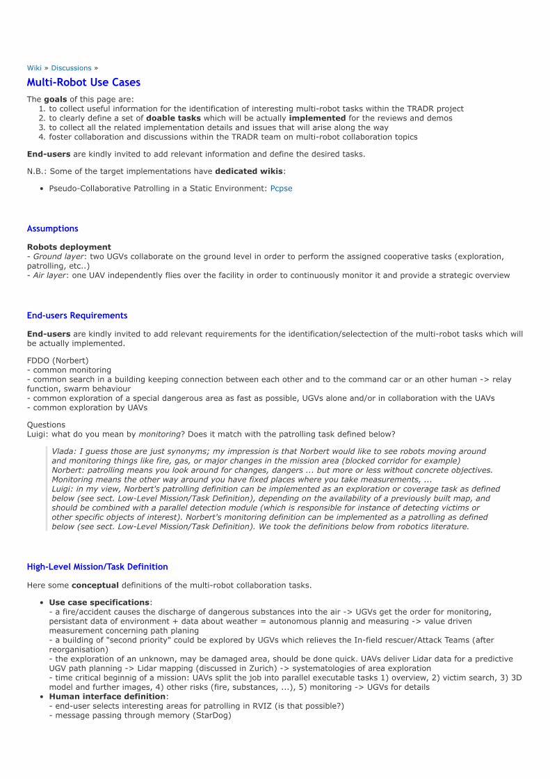
Multi‐Robot Use CasesThe goals of this page are:1. to collect useful information for the identification of interesting multirobot tasks within the TRADR project2. to clearly define a set of doable tasks which will be actually implemented for the reviews and demos3. to collect all the related implementation details and issues that will arise along the way4. foster collaboration and discussions within the TRADR team on multirobot collaboration topics
Endusers are kindly invited to add relevant information and define the desired tasks.
N.B.: Some of the target implementations have dedicated wikis:
PseudoCollaborative Patrolling in a Static Environment: Pcpse
Assumptions
Robots deployment Ground layer: two UGVs collaborate on the ground level in order to perform the assigned cooperative tasks (exploration,patrolling, etc..) Air layer: one UAV independently flies over the facility in order to continuously monitor it and provide a strategic overview
End‐users Requirements
Endusers are kindly invited to add relevant requirements for the identification/selectection of the multirobot tasks which willbe actually implemented.
FDDO (Norbert) common monitoring common search in a building keeping connection between each other and to the command car or an other human > relayfunction, swarm behaviour common exploration of a special dangerous area as fast as possible, UGVs alone and/or in collaboration with the UAVs common exploration by UAVs
Questions Luigi: what do you mean by monitoring? Does it match with the patrolling task defined below?
Vlada: I guess those are just synonyms; my impression is that Norbert would like to see robots moving aroundand monitoring things like fire, gas, or major changes in the mission area (blocked corridor for example) Norbert: patrolling means you look around for changes, dangers ... but more or less without concrete objectives.Monitoring means the other way around you have fixed places where you take measurements, ... Luigi: in my view, Norbert's patrolling definition can be implemented as an exploration or coverage task as definedbelow (see sect. LowLevel Mission/Task Definition), depending on the availability of a previously built map, andshould be combined with a parallel detection module (which is responsible for instance of detecting victims orother specific objects of interest). Norbert's monitoring definition can be implemented as a patrolling as definedbelow (see sect. LowLevel Mission/Task Definition). We took the definitions below from robotics literature.
High‐Level Mission/Task Definition
Here some conceptual definitions of the multirobot collaboration tasks.
Use case specifications: a fire/accident causes the discharge of dangerous substances into the air > UGVs get the order for monitoring,persistant data of environment + data about weather = autonomous plannig and measuring > value drivenmeasurement concerning path planing a building of "second priority" could be explored by UGVs which relieves the Infield rescuer/Attack Teams (afterreorganisation) the exploration of an unknown, may be damaged area, should be done quick. UAVs deliver Lidar data for a predictiveUGV path planning > Lidar mapping (discussed in Zurich) > systematologies of area exploration time critical beginnig of a mission: UAVs split the job into parallel executable tasks 1) overview, 2) victim search, 3) 3Dmodel and further images, 4) other risks (fire, substances, ...), 5) monitoring > UGVs for detailsHuman interface definition: enduser selects interesting areas for patrolling in RVIZ (is that possible?) message passing through memory (StarDog)

Low‐Level Mission/Task Definition
Here we define a small collection of lowlevel multirobot tasks which can be relevant within the TRADR project:
Offline coverage: cover (with sensory perceptions) an environment which is a priori known in the most "efficient" way.Patrolling: an environment must be continually surveyed by a group of robots such that each point is visited/coveredwith equal frequency given a graphrepresentation of the environment (nodes represent reachable and safe regions,edges represent traversable paths joining them), patrolling requires continuously visiting all the graph nodes so as tominimize the time lag between two visits. In an automated surveillance system, at each goal station, the robot stops andanalyses the scene searching for victims, scene variations or abandoned/removed objects. NOTE: patrolling is apersistent task, it never ends, no notion of completeness.Online coverage (aka exporation): cover (with sensory perceptions) an unknown environment in the most "efficient"way. See below Exploration Requirements.
Vlada: Not feasible during Y3, let's focus on Patrolling Luigi: PSE and PLDE had the priority
Sensor network deployment: deploy robot sensors in order to completely cover a given region and guarantee uniformspatial density. This requires the deployment of a significant number of robots.
Vlada: Nice to have, but again, patrolling makes more sense with our resorces Luigi: here the list just aims at identifying interesting tasks (at least in principle)
In this context, efficiency can be evaluated by defining suitable metrics which take into account task completion time,traveled path, used communication bandwidth, etc.
A multirobot task can be defined within one or multiple sorties.
Single‐sortie Missions
In a singlesortie mission the two UGVs can be required to perform one of the following tasks:
Y3: Autonomous patrolling: a map of the environment is already available and provided to the robots; robotautonomously plan their paths in order to visit/cover all the regions of the environment with equal frequency.Y3: Assigned waypoints patrolling: a map of the environment is already available and provided to the robots; usersassign a set of waypoints to the robot team by using a suitable GUI; the robots negotiate the waypoints and thenautonomously plan their paths in oder to cyclically visit all the waypoints without interfering with each other.
Vlada: From the implementation point of view, isn't this actually an implementation of the previous point?At least the "cover" requirement? I would suggest to stop here and postpone the following point to Y4 Luigi: the pathplanning (input: start,goal,pcl > output: safe trajectory) and trajectorycontrol modulescan be arranged to be the same. The cooperative and autonomous planning algorithms which determinewhere to go (which waypoints) and when, are an important/required addon.
Y4: Exploration: the UGVs autonomously explore and map the facility.Y4: Coverage: a map of the environment is already available and provided to the robots; the UGVs autonomously plantheir paths in oder to cover the environment with sensory perceptions.Y5: Lost robot: a UGV is missed and no connection to the base station. But the taken path is available from waypointnavigation. The second UGV and/or UAV are looking for it.
Multi‐sortie Missions
In a multisortie mission the two UGVs can be required to perform one of the following tasks:
Parallel patrolling w/o collaboration: Map is given, user defines areas by polygons or whatever to patrol, eachrobots patrols a single area.Exploration + Patrolling: in a first sortie, the robots explore the environment and build a map; in a second sortie therobots execute a patrolling task (autonomous or through assigned waypoints) by exploiting the previously built mapExploration + Coverage: in a first sortie, the robots explore the environment and build a map; in a second sortie therobots execute a coverage task by exploiting the previously built map
Target Implementations
Here we specify the multirobot tasks that will be actually implemented for reviews and demos.
1. Pseudo‐Collaborative Patrolling in a Static Environment (PCPSE)
This is a Vlada's proposal for TJEX/TEVAL 2016, Luigi is editing/commenting as well. Since Abel and Renaud expect to have multirobotmapping/cooperation not sooner than end of Y3, let's define lighter versionof patrolling. We can still claim that it is multirobot, but these robots will perform patrolling of distinct areas in parallel. Let'sassume a patrolling mission in a static environment. A map of the environment is already available and was built in a previousdedicated sortie. If we get this running during summer, we can build and test based on it until review, where additional interrobot communication and planning could be added and tested.

See the dedicated page: PCPSE
2. Patrolling in a Static Environment (PSE)
We can start experimenting with the simplest multirobot task: a patrolling mission in a static environment (see Issues>Dynamic Environments below). A map of the environment is already available and was built in a previous dedicated sortie. Inorder to implement a PSE algorithm the following requirements are fundamental.
PCPSE Table of Requirements
ID Description StatusEstimatedDeliveryDate
KeyPartners Notes Issues/Questions
PSE1 Environment is static
PSE2
The environment map isalready available andgiven as input to therobots
OK Nowavailable
ETH
PSE3
The robots are able tocontinuously localizethemselves w.r.t. thegiven map
? ? ETHThis means the robotSshare a single "map"reference frame
PSE4
Robots are able tocontinuouslycommunicate andexchange their positionsand relevant data
? ?FRA,ROMA, ...
In principle, if a map isavailable and theenvironment is static, allthe robot trajectoriescan be planned andshared beforehand(when mission starts)without requiring furtherdata communications.Nevertheless, exacttemporal execution ofthe planned trajectoriescannot be guaranteed ina USAR environment andeach robot can be seenas an highdynamicobstacle by the otherrobots. Therefore, forrobustness reasons, it isdesirable that robotskeep on continuouslyexchange information (atleast their estimatedpositions) and possibleplan updates.
See below General Issues>Multirobot communication
PSE5GUIdefinition/implementationfor waypoints assignment
? ?FRA,ROMA,CTU, ...
Patrolling can becompletely autonomous(if the waypoints areautonomously plannedby the algorithm) orendusers can explicitlyassign a set ofinteresting goal stations.See more details in LowLevel Mission/TaskDefinition above.
PSE6 TRADR DB managementfor persistency
? ?
FRA,ROMA,ETH,CTU, ...
We need to define andstore relevant datastructures in MongoD(e.g. maps,traversability, relatedinfos). We need toimplement the interfacetowards MongoDB.
PSE7PSE algorithmimplementation WIP TEval ROMA
Currentlytesting/developing undersimulation
...
Consider a starting narrow

PSE8Dynamic mapping (atleast considering robotocclusions)
TODO TEvalETH,CTU,ROMA
Mapping has to be ableto clean robotghost/trails from thebuilt map.
corridor, robot A starts behindrobot B. Robot A will perceiverobot B as an obstacle. Robot Amapper module must be able toclean the ghost/trail of robot Bfrom the map, otherwise the pathplanner of robot A won't be ableto compute a plan and movefrom its starting position. So wehave to avoid robot A from beingtrapped by ghosts :) . In orderto cope with that, without adecent dynamic mapping, wehave to (1) select a sufficientlylarge region where to the start(2) suitably arrange the initialrobot positions (3) suitablyprocrastinate the start of robot A(4) guide the robots to patrol twodistinct and wellseparatedregions in order to avoid furtherproblematic meetings (5) dosome tests...
PSE+ ... ... ... ... ... ...
To be defined:
Do robots start from the same point or from distinct points?
3. Patrolling in a Low‐Dynamic Environment (PLDE)
As a second step we can consider an environment with lowdynamic objects (see Issues>Dynamic Environments below). Alsoin this case, a map of the environment is already available and was built in a previous dedicated sortie. In order to implementa PLDE algorithm the following requirements are fundamental.
PLDE Table of Requirements
ID Description StatusEstimatedDeliveryDate
KeyPartners Notes Issues/Questions
PLDE1
Environment has some lowdynamic features (e.g. someobstacles were moved w.r.t.previous mapping sortie)
See below GeneralIssues>DynamicEnvironment
PLDE2The environment map isalready available and givenas input to the robots
OKNowavailable ETH
PLDE3
The robots are able tocontinuously localizethemselves w.r.t. the givenmap
? ? ETH This means the robotS share asingle "map" reference frame
PLDE4
Robots are able tocontinuously communicateand exchange theirpositions and relevant data
? ? FRA,ROMA, ...
See below GeneralIssues>Multirobotcommunication
PLDE5GUIdefinition/implementation forwaypoints assignment
? ?FRA,ROMA,CTU, ...
Patrolling can be completelyautonomous (if the waypoints areautonomously planned by thealgorithm) or endusers canexplicitly assign a set ofinteresting goal stations. Seemore details in LowLevelMission/Task Definition above.
PLDE6
Mapping modulecommunicates the necessarymap updates to the plannermodule (as early as possible)taking into accountmoved/changed obstacles
? ? ETH
For efficiency reasons, it isdesirable the mapping modulealso communicates a geometricaldescription of the changedregions to the planner module(so as to allow efficient localupdates oftraversability/segmentation data)

PLDE7 TRADR DB management forpersistency
? ?
FRA,ROMA,ETH,CTU, ...
We need to define and storerelevant data structures inMongoD (e.g. maps,traversability, related infos). Weneed to implement the interfacetowards MongoDB.
PLDE8 PLDE algorithmimplementation
WIP TEval ROMA Currently testing/developingunder simulation
...
PLDE+ ... ... ... ... ... ...
To be defined:
Do robots start from the same point or from distinct points?
Other Tasks ...
Multi‐Robot Communication
Here we specify the communication interfaces and the data which need to be exchanged by the robots for the tasks of interest.
Required data
Pseudocollaborative Patrolling Static Environment (PCPSE): each robot must broadcast1. its position w.r.t. the shared map2. required sensory data, at the moment available ones are: flammable gasses, smoke, victims. Planned: fire and hotspot detection in thermo
3. its ability to proceed with the assigned plan if not able, broadcast an alarm informing about major change in theassigned area
Patrolling Static Environment (PSE): each robot must multicast/broadcast1. its position w.r.t. the shared map2. its planned path to the next target position3. required sensory data, at the moment available ones are: flammable gasses, smoke, victims. Planned: fire and hotspot detection in thermo (usually only one robot bears thermocam).
Patrolling LowDynamic Environment (PLDE): each robot must multicast/broadcast1. its position w.r.t. the shared map2. its planned path to the next target position3. local map updates4. required sensory data
Exploration: each robot must multicast/broadcast1. its map (global or local map updates)2. its position w.r.t. the shared map (assuming individual maps overlap and map merging/registration can besuccessfully applied)
3. its planned path to the next target position4. required sensory data
Multi‐Robot Database Management
Robot1 and Robot2 cooperatively explore the environment and need to store their data in the DB. The two following approaches can be envisioned.
Centralized multi‐robot localization and map fusion
Each robot writes its individual map into the DB. During the mission a mapfusionglobaloptimizer receives/reads theindividual maps from the DB, globally register (additional loop closure detections?) and fuse them in a new multirobot map.This new multirobot map is then sent back to each robot. Each robot relocalizes in it, replaces its individual map with thenew received/queried multirobot map and starts extending it and sharing its position w.r.t. It. In this approach, the DB storesan individual map for each robot + a new resulting multirobot map. A mechanism should be decided to manage furtherindividual map updates (which should trigger somehow the mapfusionglobaloptimizer to start a new job). PROS: kind of “simpler” centralized approach. CONS: robustness issues w.r.t. network disruption.
Decentralized multi‐robot localization and map fusion
Each robot receives/queries the individual maps coming from the other robots and is responsible of independently fusing themwith its own map. Each robot writes its map updates to the DB and share them with the other robots by using networkcommunication (or DB?). In this approach, the DB stores a map for each robot. In principle, if robots forms disconnected

subnetworks each individual map can be different from the others; on the other hand, if robot network graph is complete(each pair of robots can communicate) the individual maps should coincide up to measurement noise and assuming perfectglobal optimization (and no critical loop closure errors). Here, the DB could also be used just to store the “best” individual mapthat is built by the robots. But how? PROS: robust w.r.t. network failures CONS: more complex (obviously)
Questions
In a multirobot context, do we need to use the DB (as a common blackboard) for sharing intermediate results? See forinstance the decentralized multirobot DB management above: in principle, we could use the DB just for storing a finalacquired world representation (e.g. select the best map and just store this).
See also the discussion herehttps://redmine.ciirc.cvut.cz/projects/tradr/wiki/Database_Management_for_Mapping_and_Planning_20160609
General Issues
Dynamic Environment: the environment can change substantially over time. This has to be explicitly managed by boththe mapping and planning modules. Environment can have lowdynamic or highdynamic features depending of theconsidered timescale and actual rapidity of the changes. Low dynamic environments are in general composed of staticand lowdynamic entities that can be moved or changed at any time, such as small obstacles, barriers and walls. In thiscase, a simple and widespread approach is to detect and treat them as outliers and locally update the map. On the otherhand, highdynamic objects continuously change the environment and must be represented and tracked explicitly withsuitable techniques such as multitarget tracking. In this latter case, obstacle avoidance techniques (relying on fast dataacquisitions) are also in order after global path planning guarantees the existence of a path toward a designated goal onthe basis of the available built map. In principle, each robot can be also seen as a moving obstacle by the other robots:in this case data sharing and distributed/coordinated motion planning can efficiently manage interrobot collisionavoidance.
Vlada: Y3: Lets deal with dynamic environment by halting execution and informing enduser thatsomething major has changed goes well with patrolling task
Y4: Mutual localization: in order to collaborate the robots must know their mutual positions in their individual maps.This can be achieved by using suitable techniques such as map registration, map merging, place recognition(appearancebased localization), etc. Map registration is obviously possible when a minimal overlap among individualmaps occur so as to allow a consistent map merging. In order to ease this process we can make the robots start fromthe same point in order to guarantee an initial minimal overlap.
Vlada: Let's concentrate on this feature in Y4
Multirobot communication: a multirobot task can be actually performed as long as interrobot communication isworking and information are shared.
Ensuring communication constraints: in order to communicate, robots may be required to jointly satisfy somegeometrical constraints at all times (e.g. maintain mutual lineofsight visibility and maintain their mutual distancebelow a certain maximum threshold) or may be called for a rendezvous after communication loss lasts more than acertain time interval. This is required to guarantee better cooperation/coordination: map/information integrationshould be done as early as possible, since the availability of a shared map/information greatly facilitates thecoordination between robots.Robustness: even if one robot fails catastrophically, others should take over its subtask. Faulttolerant methodsshould be deviced. What actually happens when the robot communication completely falls down?Careful network analysis and profiling must be performed in order to ensure that the actual network bandwidth issufficient to allow all the required data to be exchanged among robots.
Vlada: For Y3, I propose to check mutual distance only to avoid collisions.Vlada: I think the following points might by addressed for Y4 if we manage to get the interrobotcommunication and robotdatabase running during Y3
Multirobot heterogeneous collaboration: w.r.t. the tasks defined above, define how to efficiently/properly considereach robot specific characteristics in the role assignment and team deployment. Can we/endusers assign different labelsto each environment region beforehand in order to suggest preferred task assignments or team deployments? (e.g. labelregions where samples have to be analysed in order to prefer their assignment to UGVs equipped with robotic arm).
Interface definition: How a single operator can efficiently guide the two UGVs and assign them a cooperative task? An efficient and(hopefully) simple interface should be defined to this aim. Is the operator allowed to interrupt a robot for assigning it a different task? Which are the allowed control modes of the single robots during a multirobot task execution? (e.g. Am I allowed tomove the camera during a patrolling? )
Clarify the control modes as well as the technologies to develop the interaction, the communication and thecollaboration between robots and humans.
Discuss problems related to the integration with the TRADR ontology, the lowlevel database (MongoDB) and the highlevel database (Stardog)
V‐REP Simulation
Installing V‐REP
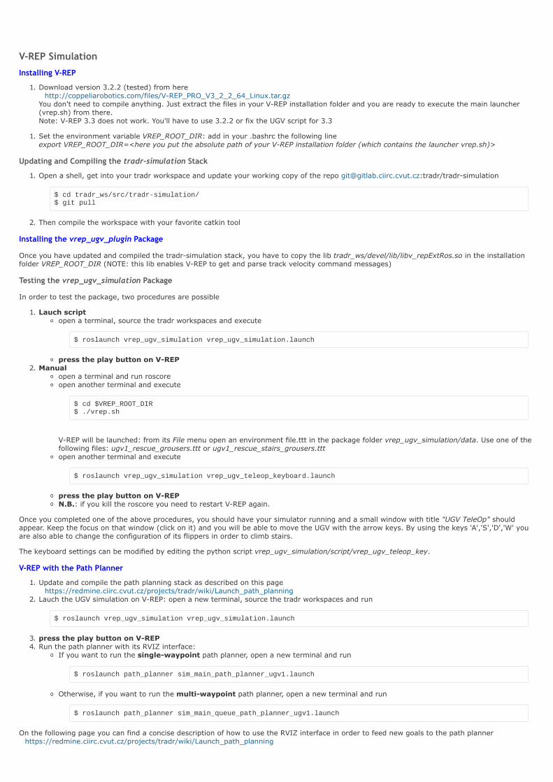
1. Download version 3.2.2 (tested) from here http://coppeliarobotics.com/files/VREP_PRO_V3_2_2_64_Linux.tar.gz
You don't need to compile anything. Just extract the files in your VREP installation folder and you are ready to execute the main launcher(vrep.sh) from there. Note: VREP 3.3 does not work. You'll have to use 3.2.2 or fix the UGV script for 3.3
1. Set the environment variable VREP_ROOT_DIR: add in your .bashrc the following line export VREP_ROOT_DIR=<here you put the absolute path of your VREP installation folder (which contains the launcher vrep.sh)>
Updating and Compiling the tradr‐simulation Stack
1. Open a shell, get into your tradr workspace and update your working copy of the repo [email protected]:tradr/tradrsimulation
$ cd tradr_ws/src/tradrsimulation/ $ git pull
2. Then compile the workspace with your favorite catkin tool
Installing the vrep_ugv_plugin Package
Once you have updated and compiled the tradrsimulation stack, you have to copy the lib tradr_ws/devel/lib/libv_repExtRos.so in the installationfolder VREP_ROOT_DIR (NOTE: this lib enables VREP to get and parse track velocity command messages)
Testing the vrep_ugv_simulation Package
In order to test the package, two procedures are possible
1. Lauch scriptopen a terminal, source the tradr workspaces and execute
$ roslaunch vrep_ugv_simulation vrep_ugv_simulation.launch
press the play button on VREP2. Manual
open a terminal and run roscoreopen another terminal and execute
$ cd $VREP_ROOT_DIR $ ./vrep.sh
VREP will be launched: from its File menu open an environment file.ttt in the package folder vrep_ugv_simulation/data. Use one of thefollowing files: ugv1_rescue_grousers.ttt or ugv1_rescue_stairs_grousers.tttopen another terminal and execute
$ roslaunch vrep_ugv_simulation vrep_ugv_teleop_keyboard.launch
press the play button on VREPN.B.: if you kill the roscore you need to restart VREP again.
Once you completed one of the above procedures, you should have your simulator running and a small window with title "UGV TeleOp" shouldappear. Keep the focus on that window (click on it) and you will be able to move the UGV with the arrow keys. By using the keys 'A','S','D','W' youare also able to change the configuration of its flippers in order to climb stairs.
The keyboard settings can be modified by editing the python script vrep_ugv_simulation/script/vrep_ugv_teleop_key.
V‐REP with the Path Planner
1. Update and compile the path planning stack as described on this pagehttps://redmine.ciirc.cvut.cz/projects/tradr/wiki/Launch_path_planning
2. Lauch the UGV simulation on VREP: open a new terminal, source the tradr workspaces and run
$ roslaunch vrep_ugv_simulation vrep_ugv_simulation.launch
3. press the play button on VREP4. Run the path planner with its RVIZ interface:
If you want to run the singlewaypoint path planner, open a new terminal and run
$ roslaunch path_planner sim_main_path_planner_ugv1.launch
Otherwise, if you want to run the multiwaypoint path planner, open a new terminal and run
$ roslaunch path_planner sim_main_queue_path_planner_ugv1.launch
On the following page you can find a concise description of how to use the RVIZ interface in order to feed new goals to the path planner https://redmine.ciirc.cvut.cz/projects/tradr/wiki/Launch_path_planning
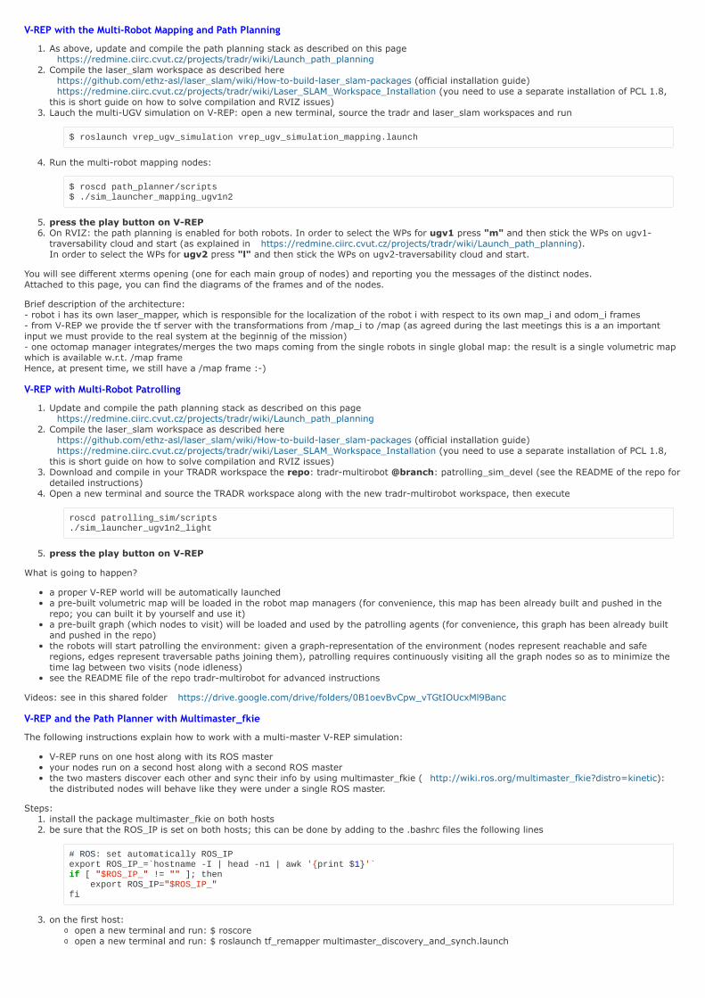
V‐REP with the Multi‐Robot Mapping and Path Planning
1. As above, update and compile the path planning stack as described on this pagehttps://redmine.ciirc.cvut.cz/projects/tradr/wiki/Launch_path_planning
2. Compile the laser_slam workspace as described here https://github.com/ethzasl/laser_slam/wiki/Howtobuildlaser_slampackages (official installation guide) https://redmine.ciirc.cvut.cz/projects/tradr/wiki/Laser_SLAM_Workspace_Installation (you need to use a separate installation of PCL 1.8,
this is short guide on how to solve compilation and RVIZ issues)3. Lauch the multiUGV simulation on VREP: open a new terminal, source the tradr and laser_slam workspaces and run
$ roslaunch vrep_ugv_simulation vrep_ugv_simulation_mapping.launch
4. Run the multirobot mapping nodes:
$ roscd path_planner/scripts $ ./sim_launcher_mapping_ugv1n2
5. press the play button on VREP6. On RVIZ: the path planning is enabled for both robots. In order to select the WPs for ugv1 press "m" and then stick the WPs on ugv1traversability cloud and start (as explained in https://redmine.ciirc.cvut.cz/projects/tradr/wiki/Launch_path_planning). In order to select the WPs for ugv2 press "l" and then stick the WPs on ugv2traversability cloud and start.
You will see different xterms opening (one for each main group of nodes) and reporting you the messages of the distinct nodes. Attached to this page, you can find the diagrams of the frames and of the nodes.
Brief description of the architecture: robot i has its own laser_mapper, which is responsible for the localization of the robot i with respect to its own map_i and odom_i frames from VREP we provide the tf server with the transformations from /map_i to /map (as agreed during the last meetings this is a an importantinput we must provide to the real system at the beginnig of the mission) one octomap manager integrates/merges the two maps coming from the single robots in single global map: the result is a single volumetric mapwhich is available w.r.t. /map frame Hence, at present time, we still have a /map frame :)
V‐REP with Multi‐Robot Patrolling
1. Update and compile the path planning stack as described on this pagehttps://redmine.ciirc.cvut.cz/projects/tradr/wiki/Launch_path_planning
2. Compile the laser_slam workspace as described here https://github.com/ethzasl/laser_slam/wiki/Howtobuildlaser_slampackages (official installation guide) https://redmine.ciirc.cvut.cz/projects/tradr/wiki/Laser_SLAM_Workspace_Installation (you need to use a separate installation of PCL 1.8,
this is short guide on how to solve compilation and RVIZ issues)3. Download and compile in your TRADR workspace the repo: tradrmultirobot @branch: patrolling_sim_devel (see the README of the repo fordetailed instructions)
4. Open a new terminal and source the TRADR workspace along with the new tradrmultirobot workspace, then execute
roscd patrolling_sim/scripts ./sim_launcher_ugv1n2_light
5. press the play button on VREP
What is going to happen?
a proper VREP world will be automatically launcheda prebuilt volumetric map will be loaded in the robot map managers (for convenience, this map has been already built and pushed in therepo; you can built it by yourself and use it)a prebuilt graph (which nodes to visit) will be loaded and used by the patrolling agents (for convenience, this graph has been already builtand pushed in the repo)the robots will start patrolling the environment: given a graphrepresentation of the environment (nodes represent reachable and saferegions, edges represent traversable paths joining them), patrolling requires continuously visiting all the graph nodes so as to minimize thetime lag between two visits (node idleness)see the README file of the repo tradrmultirobot for advanced instructions
Videos: see in this shared folder https://drive.google.com/drive/folders/0B1oevBvCpw_vTGtIOUcxMl9Banc
V‐REP and the Path Planner with Multimaster_fkie
The following instructions explain how to work with a multimaster VREP simulation:
VREP runs on one host along with its ROS masteryour nodes run on a second host along with a second ROS masterthe two masters discover each other and sync their info by using multimaster_fkie ( http://wiki.ros.org/multimaster_fkie?distro=kinetic):the distributed nodes will behave like they were under a single ROS master.
Steps:1. install the package multimaster_fkie on both hosts2. be sure that the ROS_IP is set on both hosts; this can be done by adding to the .bashrc files the following lines
# ROS: set automatically ROS_IP export ROS_IP_=`hostname I | head n1 | awk 'print $1'` if [ "$ROS_IP_" != "" ]; then export ROS_IP="$ROS_IP_" fi
3. on the first host:open a new terminal and run: $ roscoreopen a new terminal and run: $ roslaunch tf_remapper multimaster_discovery_and_synch.launch

1. on the second host:open a new terminal and run: $ roscoreopen a new terminal and run: $ roslaunch tf_remapper multimaster_discovery_and_synch.launchopen a new terminal and run: $ roslaunch vrep_ugv_simulation vrep_ugv_simulation.launch
1. on the first host:open a new terminal and run: $ roscd path_planner/scripts; ./sim_launcher_ugv1n2
V‐REP Patrolling, Path Planning and Mapping over NIMBRO Network
Introduction: in order to develop and easily test the multirobot network framework, we have prepared a VREP robot simulator which emits thesame topics of an actual robot. Two instances of this simulator are launched, each one running on a distinct computer (as if they were two distinctactual robots). Laser mapper, traversability and path planner are normally launched (as on the actual robots). One of this computer is also used asa "tradr core" (by using a distinct roscore; clearly this is not a limitation since an additional computer can be also used without problem). Nimbrorelays are activated and fully work.
In this simulation framework, you need two computers (PC). Two instances of VREP will be launched. Each instance of VREP acts as an actual robot and will emit the same topics of an actual robot (the main ones). The simulated robot 'sim1robot' and a minimal tradrcore interface will run on the first computer. The second robot 'sim2robot' will run on the second computer.
1. Update and compile the path planning stack as described on this pagehttps://redmine.ciirc.cvut.cz/projects/tradr/wiki/Launch_path_planning
2. Update, compile and install the vrep_ugv_plugin package as explained above.3. Compile the laser_slam workspace as described here
https://github.com/ethzasl/laser_slam/wiki/Howtobuildlaser_slampackages (official installation guide) https://redmine.ciirc.cvut.cz/projects/tradr/wiki/Laser_SLAM_Workspace_Installation (you need to use a separate installation of PCL 1.8,
this is short guide on how to solve compilation and RVIZ issues)4. Now go through the following steps
setup the hostname in the configuration file of the robots 'sim1robot' and 'sim2robot' in the dir tradrnetwork/tradr_relay_conf/; open anew terminal `$ roscd tradr_relay_conf/conf` `$ gedit sim1robot.xml &` < set the prefix=ugv1 and hostname=localhost `$ gedit sim2robot.xml &` < set the prefix=ugv2 and set the hostname of your second PCremove the labels `ugv1` and `ugv2` from any other actual robot configuration file <name>robot.xmlthen run the following command `$ rosrun tradr_relay_conf generate_launchfiles.py`you can accomplish the above first steps on your PC/laptop and then synch the files between your PC/latop and the second PC (you can usersynch for instance)
in a first PC, launch the first robot 'ugv1' 1) launch VREP `$ roslaunch vrep_ugv_simulation vrep_ugv_simulation_robot_ugv1.launch` press the play button 2) launch the robot nodes and the nimbro robot relay `$ roscd path_planner/scripts` `$ ./sim_launcher_nimbro_robot 1` < set the CORE_HOSTNAME and the first arguments in the script here the usage is: ./sim_launcher_nimbro_robot <robotid> <corehostname>
in a second PC, launch the second robot 'ugv2' 1) launch VREP `$ roslaunch vrep_ugv_simulation vrep_ugv_simulation_robot_ugv2.launch` < NB use the file with suffix ugv2! press the play button 2) launch the robot nodes and the nimbro robot relay `$ roscd path_planner/scripts` `$ ./sim_launcher_nimbro_robot 2` < set the CORE_HOSTNAME and the first arguments in the script here the usage is: ./sim_launcher_nimbro_robot <robotid> <corehostname>
in the first PC, launch the minimal tradr core relay `$ roscd path_planner/scripts` `$ ./sim_launcher_nimbro_core true` < set the first arguments therein > here the usage is: ./sim_launcher_nimbro_core <RUN_SIM> where RUN_SIM=true/false specifies if we are running a simulation or not. WithREAL robots you can simply launch `$ ./sim_launcher_nimbro_core` on SIMULATION you instead have to run `$ ./sim_launcher_nimbro_core true`
now you will see a global RVIZ and the patrolling starting
in order to let the robots plan a path on the patrolling graph you have to command each robot to load the map; for each robot 1) enable on RVIZ the /ugvi/slam_marker (Interactive marker) 2) rightclick over it and select the action "Reset octomap and load previous map"
building a patrolling graph: in order to have this feature enabled you have to set BUILD_PATROLLING_GRAPH_ON_START="true" on both thescripts "path_planner/scriptsscreen_launcher_ugvmulti_lasermapper_pathplanner" and "path_planner/scripts/sim_launcher_nimbro_core"; on RVIZ, load the map on ugv1 (this procedure won't work on ugv2); press 'm' on the keyboard and stick a set of waypoint on the traversability carpet then rightclick on one of the waypoint marker and selectthe action "Patrolling send task"; the patrolling graph will be saved and can be used on further patrolling missions by setting BUILD_PATROLLING_GRAPH_ON_START="false"on both the scripts; now the patrolling will automatically start
using a saved patrolling graph: in order to have this feature enabled you have to set BUILD_PATROLLING_GRAPH_ON_START="false" on boththe scripts "path_planner/scripts/sim_launcher_nimbro_robot" and "path_planner/scripts/sim_launcher_nimbro_core"
pause/restart patrolling: on RVIZ press 'm' and then 'q' for pausing or 'w' for restarting
if you want just to test the multirobot path planning, you can set the variable ENABLE_PATROLLING=0 in both the scriptssim_launcher_nimbro_robot and sim_launcher_nimbro_core. In this case, you can set the waypoints for the two robots by using the keys "m" and "l". In order to select the WPs for the robot sim1 press "m" and then stick the WPs on ugv1traversability cloud and start (as explained in

TRADR setup »
Multi‐Robot Path Planning and Patrolling
Required Git repos and their branches
repo: tradrlocmapnav @(master) package: path_planner https://gitlab.ciirc.cvut.cz/tradr/tradrlocmapnav/tree/master/path_plannerrepo: tradrlocmapnav @(master) package: trajectory_control https://gitlab.ciirc.cvut.cz/tradr/tradrlocmapnav/tree/master/trajectory_controlrepo: tradrmsgs @(master) package: trajectory_control_msgs https://gitlab.ciirc.cvut.cz/tradr/tradrmsgs
Please, install Octomap packages in oder to compile the path_planner package. You can find a concise documentation at https://gitlab.ciirc.cvut.cz/tradr/tradrlocmapnav/blob/master/path_planner/README.md.
Launch the Basic Modules Needed by the Path Planner
Launch the ugv_multi drivers and the new ETHZ laser mapper
on robot:
roslaunch nifti_drivers_launchers ugv_multi.launch
on robot, start the new ETH mapping: roslaunch nifti_mapping_launchers mapAndNav.launch
roslaunch laser_mapper main_laser_mapper_tf_remapped.launch
Launching the Single‐Waypoint Path Planner
First launch the basic drivers and laser mappers as described above. Then, to run the path planner and connect it to the output of the ETHZ laser mapper
on robot, start the planner:
roslaunch path_planner main_path_planner.launch
on your laptop, start our rviz interface:
roslaunch path_planner rviz_path_planning.launch
On RVIZ, you can set a goal for the planner by using the dedicated interactive marker. The interactive marker (a sphere) will appear over therobot when you launch the path_planner node.1. Move the marker at your desired position (hold left click on it and move it w.r.t. image plane; if you also hold SHIFT button you will changethe depth of the marker)
2. Then rightclick on it and select from the menu the action "Select Goal". If you want to abort the goal once is selected, select the action"Abort Goal" from the same menu.
3. Text messages will appear over the marker explaining you what is happening. The marker color will change accordingly: Grey, path planner is waiting for a goal selection Yellow, the path planner is planning Green, a path has been found Red, the path planner could not find a path
N.B.: a path to the designated goal can be actually computed if the shown traversability map actually "connect" the goal and the robot positions.You may be required to wait few seconds till the traversability node actually complete the traversability map construction from the ICP mapperinputs.
Once a path has been found, the path planner will publish it towards the trajectory controller which will make the robot automatically follow thepath.
There are visualization topics for the planned path, the normals of the point cloud and the merged point clouds. If you launch our scriptrviz_path_planning.launch, you will find everything already set up.

Launching the Multi‐Waypoint Path Planner
First launch the basic drivers and laser mappers as described above. Then, to run the multiwaypoint path planner and connect it to the output of the ETHZ mapper
on robot, start the planner:
roslaunch path_planner main_queue_path_planner.launch
on your laptop, start our rviz interface:
roslaunch path_planner rviz_path_planning.launch
On RVIZ:1. Press the key 'M' in order to add a new waypoint directly on the traversability cloud. You can move each created waypoint by holding rightclick on it and moving. The waypoints should automatically stick to the traversability cloud.
2. Once you have selected your desired number of waypoints you can right click on one of them and select from the menu the action "AppendTask". If you want the robot to continuously revisit the waypoints you set (cyclic path), then select the action "Append Cyclic Task".
3. The marker colors will change accordingly: Orange, the marker has not been added Yellow, the path planner is planning Green, a path has been found Red, the path planner could not find a path
4. Once the waypoints get green, you can right click on one of them and select from the menu the action "Stop the controller" in order to stopthe trajectory control and the robot.
Multi‐robot Patrolling, Path Planning and Mapping over Nimbro Network
Before starting this procedure, you have to build a map of the environment and save it. In order to achieve that you can execute just the following step 1 and step 2 on one selected robot. Once the selected robot is active and you get the global RVIZ interface running, move the robot around and build your map. Once you are satisfied with the map, you can save it by enabling and using the /ugvi/slam_marker (Interactive marker): rightclick on it and selectthe action "Save current map and trajectory".
(1) on your laptop (used as core) and on the two selected robots (for instance, you can use roma and eth robot): setup the nimbro configuration file of each robot in the dir tradrnetwork/tradr_relay_conf/
you can accomplish this first step on your laptop and then synch the files between your laptop and both the selected robots (you can usersynch for instance)open a new terminal `$ roscd tradr_relay_conf/conf` `$ gedit <your robotname>robot.xml &` see the README.md of the package tradr_relay_conf which explains how to setup the nimbro configuration file. The labeling in romarobot.xml and ethrobot.xml files should be the following `romarobot>prefix: ugv1` this corresponds to a multirobot robot_id = 1 `ethrobot>prefix: ugv2` this corresponds to a multirobot robot_id = 2 N.B. the label `ugv1` and `ugv2` are used to label the robots which will be actually used in the nimbro network for patrolling and pathplanning. These labels can be used for activating a pair of simulated robots OR a pair of actual robots, but only a pair of robots at once! This means that when you use `ugv1` and `ugv2` for romarobot::prefix and ethrobot::prefix, you should remove these labels from sim1robot::prefix and sim2robot::prefix, otherwise nimbro won't work.set and check the configuration variables in the two scripts "path_planner/scripts/screen_launcher_ugvmulti_lasermapper_pathplanner" and"path_planner/scripts/sim_launcher_nimbro_core", in particular set the same PATROLLING_MAP_NAME=DIAG3D (this corresponds to a folder patrolling_sim/maps/DIAG3D which must exist)then run the following command `$ rosrun tradr_relay_conf generate_launchfiles.py`if you want you can now synch the files with rsynch between your laptop and both robots
(2) copy your map and graph files on each robot and on your laptop
copy the saved map files ('map.bt map.ply trajectory.csv') on each robot and on your main laptop in the ".ros" folderto this aim, you can use for instance the script path_planning/scripts/copy_maps_to_robots
(3) on the first robot ugv1
start the robot in the same position where you started the robot which built the saved map (reference starting position)kill all the nodes which are running on the robot: you can do that by executing the following command on the robot `$killall 9 screen; screen wipe`open a new terminal `$ rosrun tradr_relay_conf generate_launchfiles.py` `$ roscd path_planner/scripts`then launch the main script `$ ./screen_launcher_ugvmulti_lasermapper_pathplanner <robotprefix> <robotid> <corehostname>` for instance on roma robot (tagged `ugv1`) `$ ./screen_launcher_ugvmulti_lasermapper_pathplanner 1 192.168.2.54` and on eth robot (tagged `ugv2`) `$ ./screen_launcher_ugvmulti_lasermapper_pathplanner 2 192.168.2.54` in order to kill everything you can use `$ killall 9 screen; screen wipe`
(4) on the laptop
check the file /etc/hosts and if needed add your robot hostnameIPsopen a new terminal and run `$ rosrun tradr_relay_conf generate_launchfiles.py` `$ roscd path_planner/scripts` `$ ./sim_launcher_nimbro_core <RUN_SIM>` where RUN_SIM=true/false specifies if we are running a simulation or not. With REAL robots you can simply launch `$ ./sim_launcher_nimbro_core` on SIMULATION you instead have to run `$ ./sim_launcher_nimbro_core true`now you will see a global RVIZload the map on the first robot: enable on RVIZ the /ugv1/slam_marker (Interactive marker), rightclick over it and select the action "Resetoctomap and load previous map"
(5) on the second robot ugv2
start the robot in the same position where you started the robot which built the saved map (reference starting position)repeat the actions described on the step 3 above for the first robotload the map: enable on RVIZ the /ugv2/slam_marker (Interactive marker), rightclick over it and select the action "Reset octomap and loadprevious map"
(6) on the laptop: building a patrolling graph
in order to have this feature enabled you have to set BUILD_PATROLLING_GRAPH_ON_START="true" on both the scripts"path_planner/scriptsscreen_launcher_ugvmulti_lasermapper_pathplanner" and "path_planner/scripts/sim_launcher_nimbro_core"on RVIZ, load the map on ugv1 (this procedure won't work on ugv2)press 'm' on the keyboard and stick a set of waypoint on the traversability carpetthen rightclick on one of the waypoint marker and select the action "Patrolling send task"the patrolling graph will be saved and can be then used on further patrolling missions by settingBUILD_PATROLLING_GRAPH_ON_START="false" on both the scriptsnow the patrolling will automatically start
(7) on the laptop: using a saved patrolling graph
in order to have this feature enabled you have to set BUILD_PATROLLING_GRAPH_ON_START="false" on both the scripts"path_planner/scriptsscreen_launcher_ugvmulti_lasermapper_pathplanner" and "path_planner/scripts/sim_launcher_nimbro_core"copy the saved file patrolling_sim/maps/DIAG3D/DIAG3D.graph (which is on your laptop in the map folder specified by the varPATROLLING_MAP_NAME=DIAG3D, which corresponds to the folder patrolling_sim/maps/DIAG3D) in the same folderpatrolling_sim/maps/DIAG3D/ on both robots
(optional) on the laptop: pause/restart patrolling
on RVIZ press 'm' and then 'q' for pausing or 'w' for restarting the patrolling
(optional) on the laptop: aligning a robot current map with a saved map
copy the saved map (map.bt, map.ply and trajectory.cvs) on both robots and on the laptopon RVIZ enable the interactive marker and select "Reset octomap and load previous" in order to load the saved map (which should be copiedon the selected robot)then if you want to align by using the interactive marker `$ roscd path_planner/scripts` `$ ./sim_launcher_core_interactive_point_cloud_publishers`
If you want just to test the multirobot path planning, you can set the variable ENABLE_PATROLLING=0 in both the scriptssim_launcher_nimbro_robot and sim_launcher_nimbro_core. In this case, you can set the waypoints for the two robots by using the keys "m" and "l". In order to select the WPs for the robot sim1 press "m" and then stick the WPs on ugv1traversability cloud and start (as explained inhttps://redmine.ciirc.cvut.cz/projects/tradr/wiki/Launch_path_planning).
In order to select the WPs for the robot sim2 press "l" and then stick the WPs on ugv2traversability cloud and start.
Playing with the Path Planner on V‐REP
You can find the details on this page https://redmine.ciirc.cvut.cz/projects/tradr/wiki/VREP_Simulation
Videos
TJex 2016 Mapping and Point Cloud Segmentation https://www.youtube.com/watch?v=74yp_fHpDpY&feature=youtu.be