DPR - en.ecredit.com.twen.ecredit.com.tw/webfiles/42b15e98-fc08-46c5-83da-05f0f3f13b6b.pdf · DPR...
18
DPR Digital Protection Relay � Compact design � easy to operate and set � Back-lit LCD display � Adjustable current and operation time � The use of the output contacts are programmable � Fault recording function � Sequence of event function(S.O.E/Optional) � Various communication network configurations � EMC/EMI test certified
Transcript of DPR - en.ecredit.com.twen.ecredit.com.tw/webfiles/42b15e98-fc08-46c5-83da-05f0f3f13b6b.pdf · DPR...
DPR
Digital Protection Relay
�� Compact design�� easy to operate and set�� Back-lit LCD display�� Adjustable current and operation time�� The use of the output contacts are programmable�� Fault recording function�� Sequence of event function(S.O.E/Optional)�� Various communication network configurations�� EMC/EMI test certified
Contents Features N2-4
Environmental characteristics N2-5
Constitution N2-6
Additional functions N2-7
Overcurrent relay for phase and ground faults N2-8
(OCR & OCGR)
Selective Ground Relay (SGR) N2-10
Under and Overvoltage Relay (UVR & OVR) N2-12
Over Voltage Ground Relay (OVGR) N2-14
Characteristics curve N2-16
Dimensions and ordering N2-17
N2
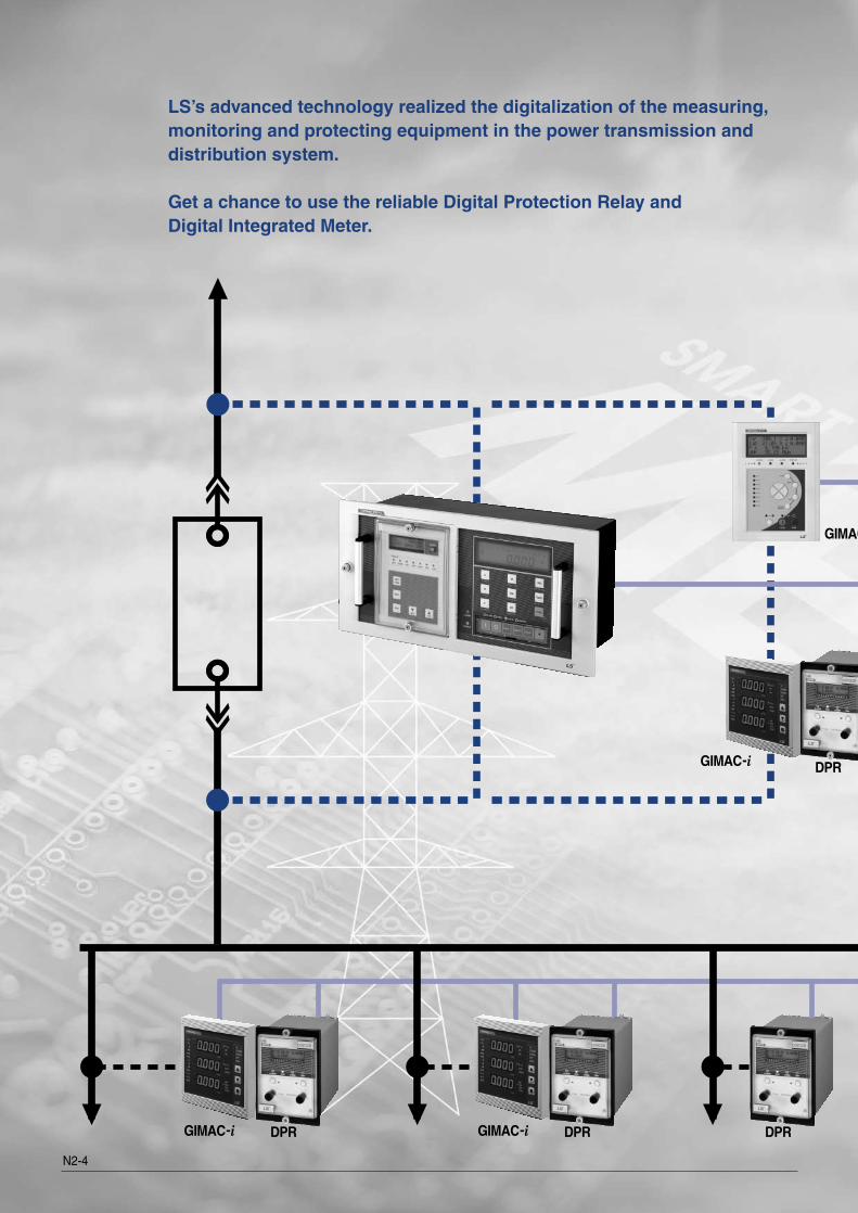
LS’s advanced technology realized the digitalization of the measuring, monitoring and protecting equipment in the power transmission and distribution system.
Get a chance to use the reliable Digital Protection Relay and Digital Integrated Meter.
DPR
GIMAC-i DPR GIMAC-i DPR DPR
GIMAC
GIMAC-i
N2-4
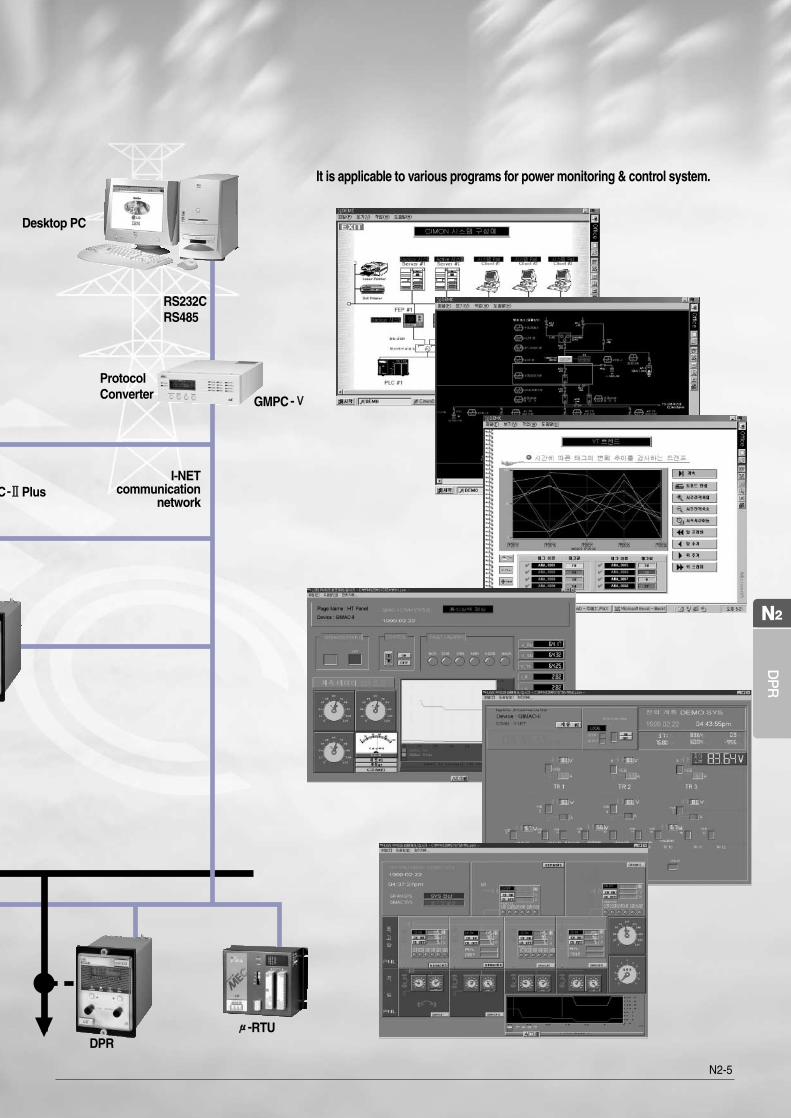
It is applicable to various programs for power monitoring & control system.
I-NET communication
network
ProtocolConverter GMPC-ⅤⅤ
Desktop PC
RS232CRS485
DPRμμ-RTU
C-ⅡⅡPlus
DP
R
N2
N2-5
N2-6
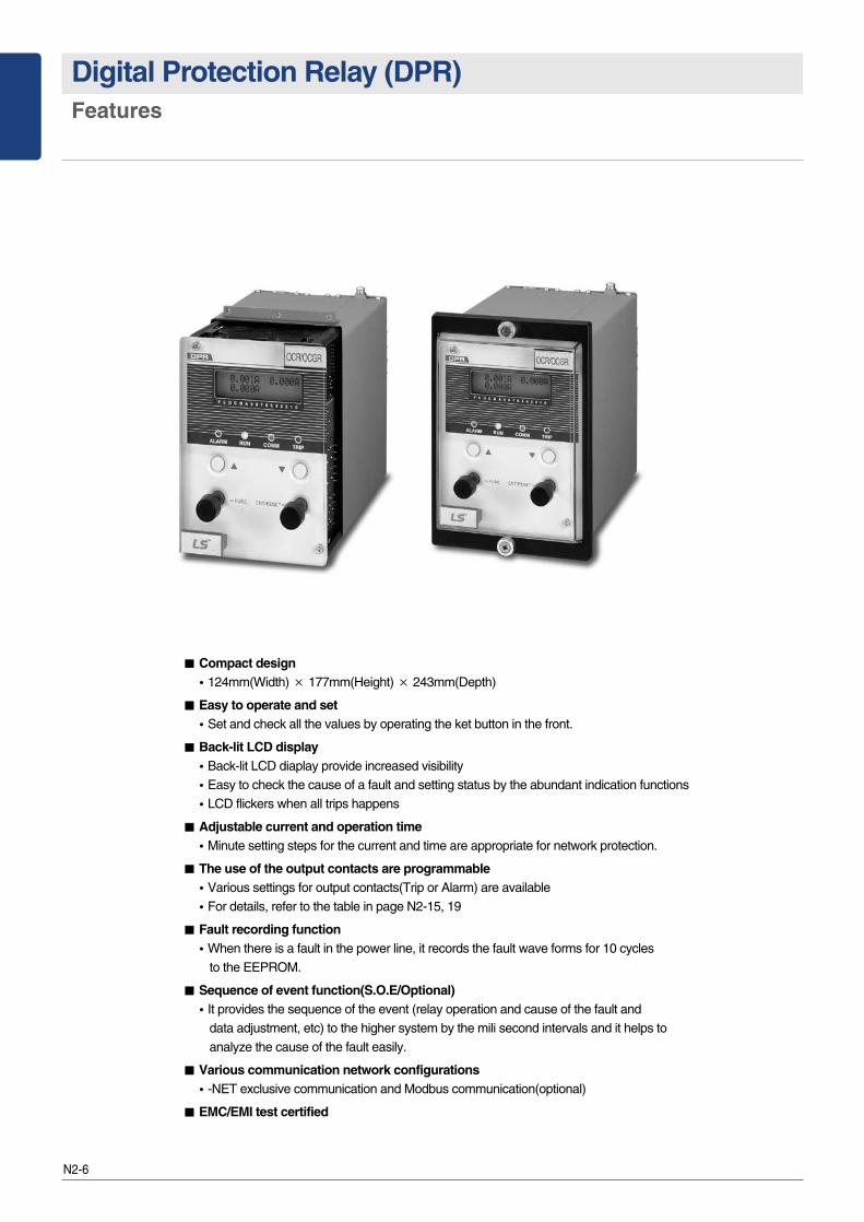
Digital Protection Relay (DPR)Features
�� Compact design�124mm(Width) × 177mm(Height) × 243mm(Depth)
�� Easy to operate and set�Set and check all the values by operating the ket button in the front.
�� Back-lit LCD display�Back-lit LCD diaplay provide increased visibility�Easy to check the cause of a fault and setting status by the abundant indication functions�LCD flickers when all trips happens
�� Adjustable current and operation time�Minute setting steps for the current and time are appropriate for network protection.
�� The use of the output contacts are programmable�Various settings for output contacts(Trip or Alarm) are available�For details, refer to the table in page N2-15, 19
�� Fault recording function�When there is a fault in the power line, it records the fault wave forms for 10 cycles
to the EEPROM.
�� Sequence of event function(S.O.E/Optional)�It provides the sequence of the event (relay operation and cause of the fault and
data adjustment, etc) to the higher system by the mili second intervals and it helps to analyze the cause of the fault easily.
�� Various communication network configurations�-NET exclusive communication and Modbus communication(optional)
�� EMC/EMI test certified
N2-7
DP
R
N2
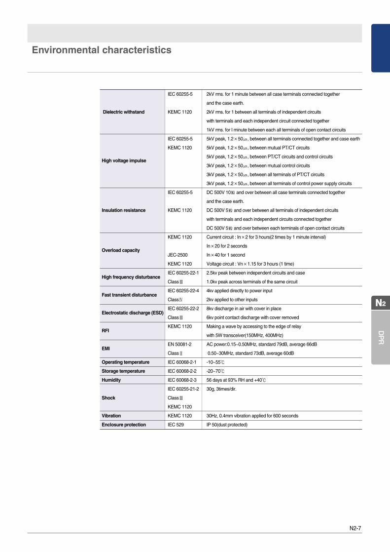
Environmental characteristics
IEC 60255-5 2kV rms. for 1 minute between all case terminals connected together
and the case earth.
Dielectric withstand KEMC 1120 2kV rms. for 1 between all terminals of independent circuits
with terminals and each independent circuit connected together
1kV rms. for I minute between each all terminals of open contact circuits
IEC 60255-5 5kV peak, 1.2×50㎲, between all terminals connected together and case earth
KEMC 1120 5kV peak, 1.2×50㎲, between mutual PT/CT circuits
High voltage impulse5kV peak, 1.2×50㎲, between PT/CT circuits and control circuits
3kV peak, 1.2×50㎲, between mutual control circuits
3kV peak, 1.2×50㎲, between all terminals of PT/CT circuits
3kV peak, 1.2×50㎲, between all terminals of control power supply circuits
IEC 60255-5 DC 500V 10㏁ and over between all case terminals connected together
and the case earth.
Insulation resistance KEMC 1120 DC 500V 5㏁ and over between all terminals of independent circuits
with terminals and each independent circuits connected together
DC 500V 5㏁ and over between each terminals of open contact circuits
KEMC 1120 Current circuit : In×2 for 3 hours(2 times by 1 minute interval)
Overload capacityIn×20 for 2 seconds
JEC-2500 In×40 for 1 second
KEMC 1120 Voltage circuit : Vn×1.15 for 3 hours (1 time)
High frequency disturbanceIEC 60255-22-1 2.5kv peak between independent circuits and case
ClassⅢ 1.0kv peak across terminals of the same circuit
Fast transient disturbance IEC 60255-22-4 4kv applied directly to power input
ClassⅣ 2kv applied to other inputs
Electrostatic discharge (ESD)IEC 60255-22-2 8kv discharge in air with cover in place
ClassⅢ 6kv point contact discharge with cover removed
RFIKEMC 1120 Making a wave by accessing to the edge of relay
with 5W transceiver(150MHz, 400MHz)
EMIEN 50081-2 AC power:0.15~0.50MHz, standard 79dB, average 66dB
ClassⅡ 0.50~30MHz, standard 73dB, average 60dB
Operating temperature IEC 60068-2-1 -10~55℃
Storage temperature IEC 60068-2-2 -20~70℃
Humidity IEC 60068-2-3 56 days at 93% RH and +40℃
IEC 60255-21-2 30g, 3times/dir.
Shock ClassⅢ
KEMC 1120
Vibration KEMC 1120 30Hz, 0.4mm vibration applied for 600 seconds
Enclosure protection IEC 529 IP 50(dust protected)
N2-8
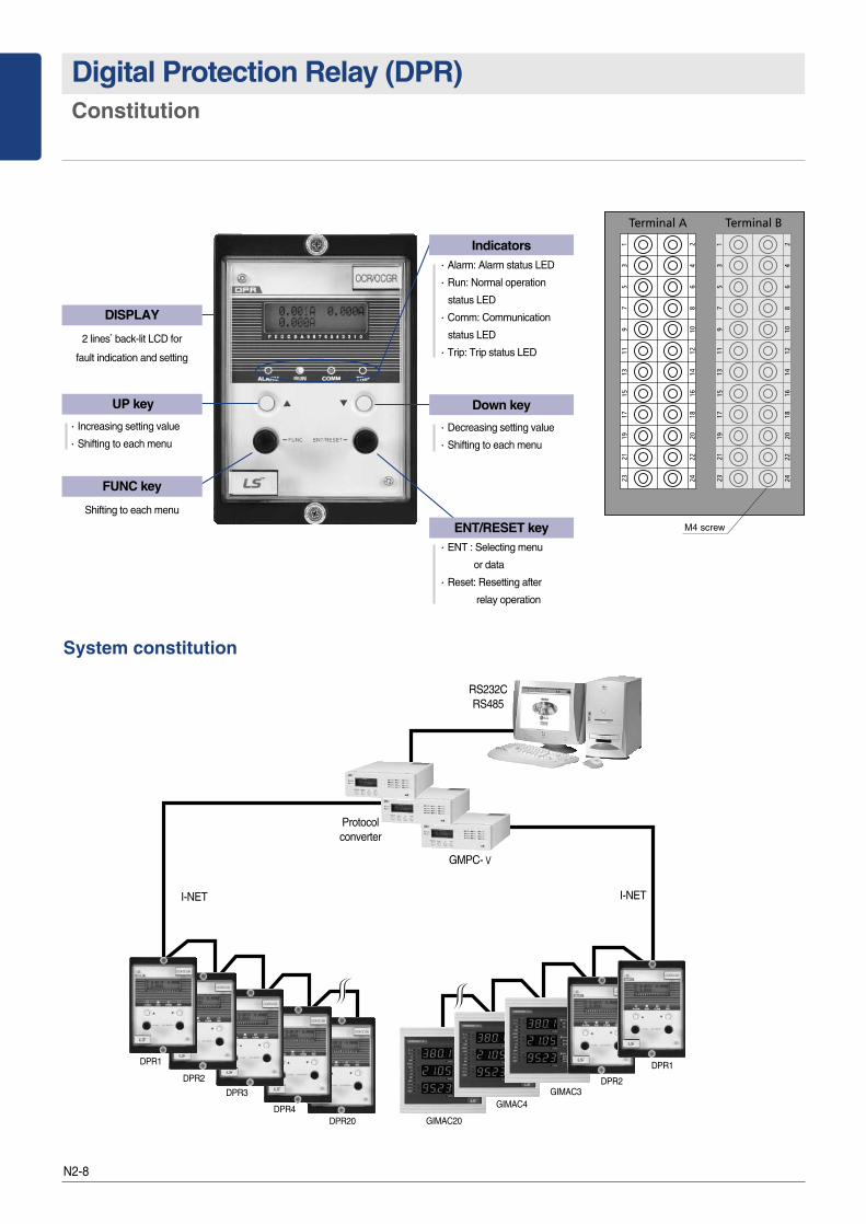
Digital Protection Relay (DPR)Constitution
M4 screw
System constitution
DISPLAY
2 lines’back-lit LCD for
fault indication and setting
UP key
∙Increasing setting value
∙Shifting to each menu
ENT/RESET key∙ENT : Selecting menu
or data
∙Reset: Resetting after
relay operation
Down key
∙Decreasing setting value
∙Shifting to each menu
Indicators∙Alarm: Alarm status LED
∙Run: Normal operation
status LED
∙Comm: Communication
status LED
∙Trip: Trip status LED
FUNC key
Shifting to each menu
I-NET I-NET
RS232CRS485
GMPC-Ⅴ
Protocolconverter
DPR1
DPR2
DPR3
DPR4
DPR2
DPR20
DPR1
GIMAC20
GIMAC4GIMAC3
N2-9
DP
R
N2
Additional functions
Constant-supervision with self-diagnosticsHigh reliability of relay will be provided by various self-diagnostics function. When errors occurs it will be displayed “Error No.”at LCDdisplay window, then the front ALARM LED lights on and LCD display window flickers on also.At the same time ALARM relay(Sys fail) will be output.1. internal ROM check: “Error 1”2. internal RAM check: “Error 2”3. A/D converter check: “Error 3”4. CPU watchdog check: “Error 4”5. Power supply check: “Error 5”6. EEPROM(Backup memory) check: “Error 6”7. Calibration check: “Error 7”
When the self-diagnostics error happens, the relay is not operated until the cause of that fault is cleared.
Fault records 1. The fault curves are recorded into EEPROM when line fault happens, which will provide fast and correct grasping for the cause of a fault.2. Storage the sample value of each phase for 10 cycles before and after the fault�5 cycles before the fault�5 cycles after the fault�8 samples for a cycle
3. A fault recording information is available for ascertaining them via communications.
Sequence of event (S.O.E) Many events (including relay operation, cause of fault, data adjustment) can be provided to the higher system1. Kinds of event�The cause of a relay operation(trip) �The data adjustment of a relay�Error occurrence of auto-diagnostics�Relay resetting
2. Twenty events are stored in a buffer (maximum)
Communication specification1. I-NET communication
High speed, high reliability of serial communication by use of the custom LSI(GC829016) developed by LSIS 1) Data rate : 250kbps2) Cable length : 1000m(max.)3) Insulation : Pulse Transformer 4) Connection : 4 Wires multi-drop5) Signal modulation : Bipolar modulation6) Connectable quantity : max. 20units per a GMPC(a protocol converter)7) Address : Parameter setting from 1 to 2558) Communication cable : Low capacitance LAN interface cable�Spec : LIREV AMESB 22AWG 2-pair (1/0.643)�Impedance : 10MHz, 120(Ϊ)�Termination : Please use it by connecting 2 resistors with each end of cable
2. MODBUS communication (Optional)�FIELD BUS open protocol applied�Please contact us before applying this communication method
N2-10
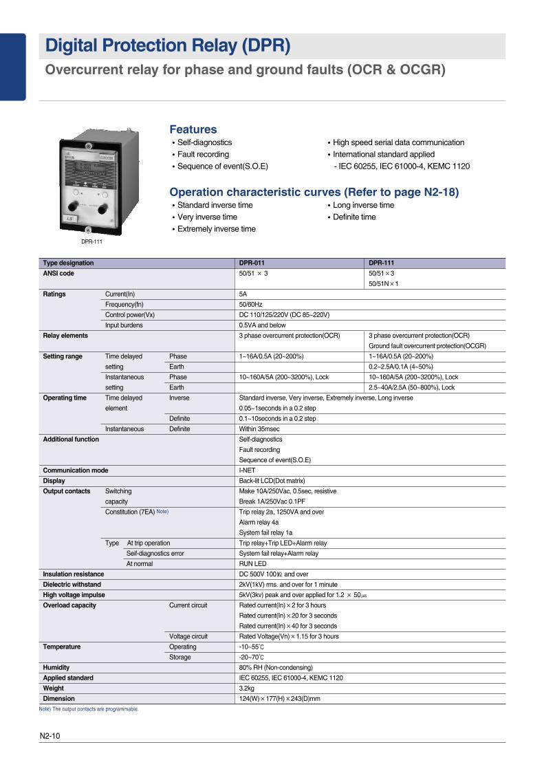
Digital Protection Relay (DPR)Overcurrent relay for phase and ground faults (OCR & OCGR)
Features�Self-diagnostics �High speed serial data communication�Fault recording �International standard applied�Sequence of event(S.O.E) - IEC 60255, IEC 61000-4, KEMC 1120
Operation characteristic curves (Refer to page N2-18)�Standard inverse time �Long inverse time�Very inverse time �Definite time �Extremely inverse time
DPR-111
Type designation DPR-011 DPR-111
ANSI code 50/51 × 3 50/51×3
50/51N×1
Ratings Current(In) 5A
Frequency(fn) 50/60Hz
Control power(Vx) DC 110/125/220V (DC 85~220V)
Input burdens 0.5VA and below
Relay elements 3 phase overcurrent protection(OCR) 3 phase overcurrent protection(OCR)
Ground fault overcurrent protection(OCGR)
Setting range Time delayed Phase 1~16A/0.5A (20~200%) 1~16A/0.5A (20~200%)
setting Earth 0.2~2.5A/0.1A (4~50%)
Instantaneous Phase 10~160A/5A (200~3200%), Lock 10~160A/5A (200~3200%), Lock
setting Earth 2.5~40A/2.5A (50~800%), Lock
Operating time Time delayed Inverse Standard inverse, Very inverse, Extremely inverse, Long inverse
element 0.05~1seconds in a 0.2 step
Definite 0.1~10seconds in a 0.2 step
Instantaneous Definite Within 35msec
Additional function Self-diagnostics
Fault recording
Sequence of event(S.O.E)
Communication mode I-NET
Display Back-lit LCD(Dot matrix)
Output contacts Switching Make 10A/250Vac, 0.5sec, resistive
capacity Break 1A/250Vac 0.1PF
Constitution (7EA) Note) Trip relay 2a, 1250VA and over
Alarm relay 4a
System fail relay 1a
Type At trip operation Trip relay+Trip LED+Alarm relay
Seif-diagnostics error System fail relay+Alarm relay
At normal RUN LED
Insulation resistance DC 500V 100㏁ and over
Dielectric withstand 2kV(1kV) rms. and over for 1 minute
High voltage impulse 5kV(3kv) peak and over applied for 1.2 × 50㎲
Overload capacity Current circuit Rated current(In)×2 for 3 hours
Rated current(In)×20 for 3 seconds
Rated current(In)×40 for 3 seconds
Voltage circuit Rated Voltage(Vn)×1.15 for 3 hours
Temperature Operating -10~55℃
Storage -20~70℃
Humidity 80% RH (Non-condensing)
Applied standard IEC 60255, IEC 61000-4, KEMC 1120
Weight 3.2kg
Dimension 124(W)×177(H)×243(D)mm
Note) The output contacts are programmable.
N2-11
DP
R
N2
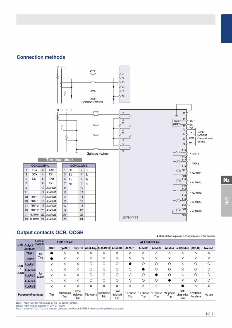
Connection methods
Output contacts OCR, OCGR
1
3
5
7
9
11
13
15
17
19
21
23
2
4
6
8
10
12
14
16
18
20
22
24
OCR/OCGR-AF.G
DC+
DC-
TRIP 1
TRIP 1
TRIP 2
TRIP 2
ALARM1
ALARM1
TX0
TX1
RX0
RX1
ALARM2
ALARM2
ALARM3
ALARM3
ALARM4
ALARM4
ALARM5
ALARM5
1
3
5
7
9
11
13
15
17
19
21
23
2
4
6
8
10
12
14
16
18
20
22
24
OCR/OCGR-B
Rk
Sk
Tk
Nk
Rl
Sl
Tl
Nl
3phase 4wires
3phase 3wires
DPR-111
Terminal block
Note 1) Alarm relay can not be used for Trip (CB control) contacts.Note 2) Alarm-I4 is not available for DPR-011(OCR)Note 3) In case of Trip1, Trip2, the contacts, status are stored as an EVENT, if they were changed during operation
Outputcontacts
Kinds ofcontactsUnit
OCR/
OCGR
Purpose of contacts TripInstantaneous
Trip
Timedelayed
TripTrip Alarm
InstantaneousTrip
Timedelayed
Trip
“R”phaseTrip
“S”phaseTrip
“T”phaseTrip
“N”phaseTrip
Self-diagnotics
Error
OverloadPre alarm
No use
●:Default(when shipment) ○:Programmable ×:Not available
TRIP 1
TRIP 2
ALARM 1
ALARM 2
ALARM 3
ALARM 4
ALARM 5
TRIP Trip-INST Trip-TD ALM-Trip ALM-INST ALM-TD ALM- I1 ALM-I2 ALM-I3 ALM-I4 ALM-Sys Fail PICK-Up No use
TRIP RELAY ALARM RELAY
forAlarm
for Trip
●●×
×
×
×
×
×
×
×
×
×
×
×
×
×
×
×
×
×
×
×
×
○○○○×
×
×
○○○○×
×
×
○○○○×
×
×
●○○○×
×
×
○●○○×
×
×
○○●○×
×
×
○○○●×
×
×
×
×
×
×
●
×
×
○○○○×
×
×
○○○○×
N2-12
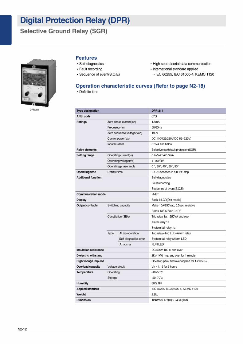
Digital Protection Relay (DPR)Selective Ground Relay (SGR)
DPR-211 Type designation DPR-211
ANSI code 67G
Ratings Zero phase current(lon) 1.5mA
Frequency(fn) 50/60Hz
Zero sequence voltage(Von) 190V
Control power(Vx) DC 110/125/220V(DC 85~220V)
Input burdens 0.5VA and below
Relay elements Selective earth fault protection(SGR)
Setting range Operating current(Io) 0.9~5.4mA/0.3mA
Operating voltage(Vo) 4~76V/4V
Operating phase angle 0�, 30�, 45�, 60�, 90�
Operating time Definite time 0.1~10seconds in a 0.1초 step
Additional function Self-diagnostics
Fault recording
Sequence of event(S.O.E)
Communication mode I-NET
Display Back-lit LCD(Dot matrix)
Output contacts Switching capacity Make 10A/250Vac, 0.5sec, resistive
Break 1A/250Vac 0.1PF
Constitution (3EA) Trip relay 1a, 1250VA and over
Alarm relay 1a
System fail relay 1a
Type At trip operation Trip relay+Trip LED+Alarm relay
Self-diagnostics error System fail relay+Alarm LED
At normal RUN LED
Insulation resistance DC 500V 100㏁ and over
Dielectric withstand 2kV(1kV) rms. and over for 1 minute
High voltage impulse 5kV(3kv) peak and over applied for 1.2×50㎲
Overload capacity Voltage circuit Vn×1.15 for 3 hours
Temperature Operating -10~55℃
Storage -20~70℃
Humidity 80% RH
Applied standard IEC 60255, IEC 61000-4, KEMC 1120
Weight 2.8kg
Dimension 124(W)×177(H)×243(D)mm
Features�Self-diagnostics �High speed serial data communication�Fault recording �International standard applied�Sequence of event(S.O.E) - IEC 60255, IEC 61000-4, KEMC 1120
Operation characteristic curves (Refer to page N2-18)�Definite time
N2-13
DP
R
N2
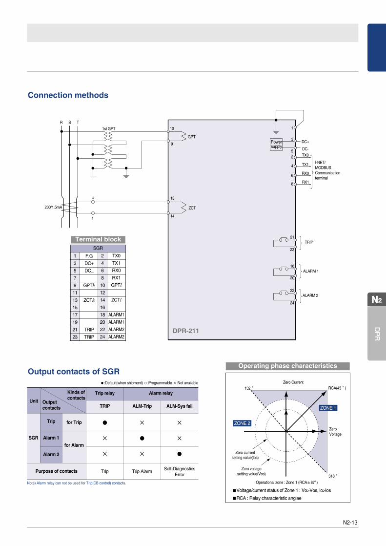
Connection methods
Output contacts of SGR
Note) Alarm relay can not be used for Trip(CB control) contacts.
1
3
5
7
9
11
13
15
17
19
21
23
2
4
6
8
10
12
14
16
18
20
22
24
SGR
F.G
DC+
DC_
GPTk
ZCTk
TRIP
TRIP
TX0
TX1
RX0
RX1
GPTl
ZCTl
ALARM1
ALARM1
ALARM2
ALARM2
�Voltage/current status of Zone 1 : Vo>Vos, lo>los
�RCA : Relay characteristic anglae
Operating phase characteristics
Zero currentsetting value(los)
Zero voltagesetting value(Vos)
Zero CurrentRCA(45°)
ZONE 1
ZONE 2
318°
132°
Operational zone : Zone 1 (RCA±87。)
Zero Voltage
Terminal block
DPR-211
Unit
SGR
Trip
Alarm 1
Alarm 2
for Trip
for Alarm
Trip relay
TRIP
Alarm relay
ALM-Trip ALM-Sys fail
●
×
×
Trip
×
●
×
Trip Alarm
×
×
●
Kinds ofcontacts
Outputcontacts
Purpose of contacts
●:Default(when shipment) ○:Programmable ×:Not available
Self-DiagnosticsError
N2-14
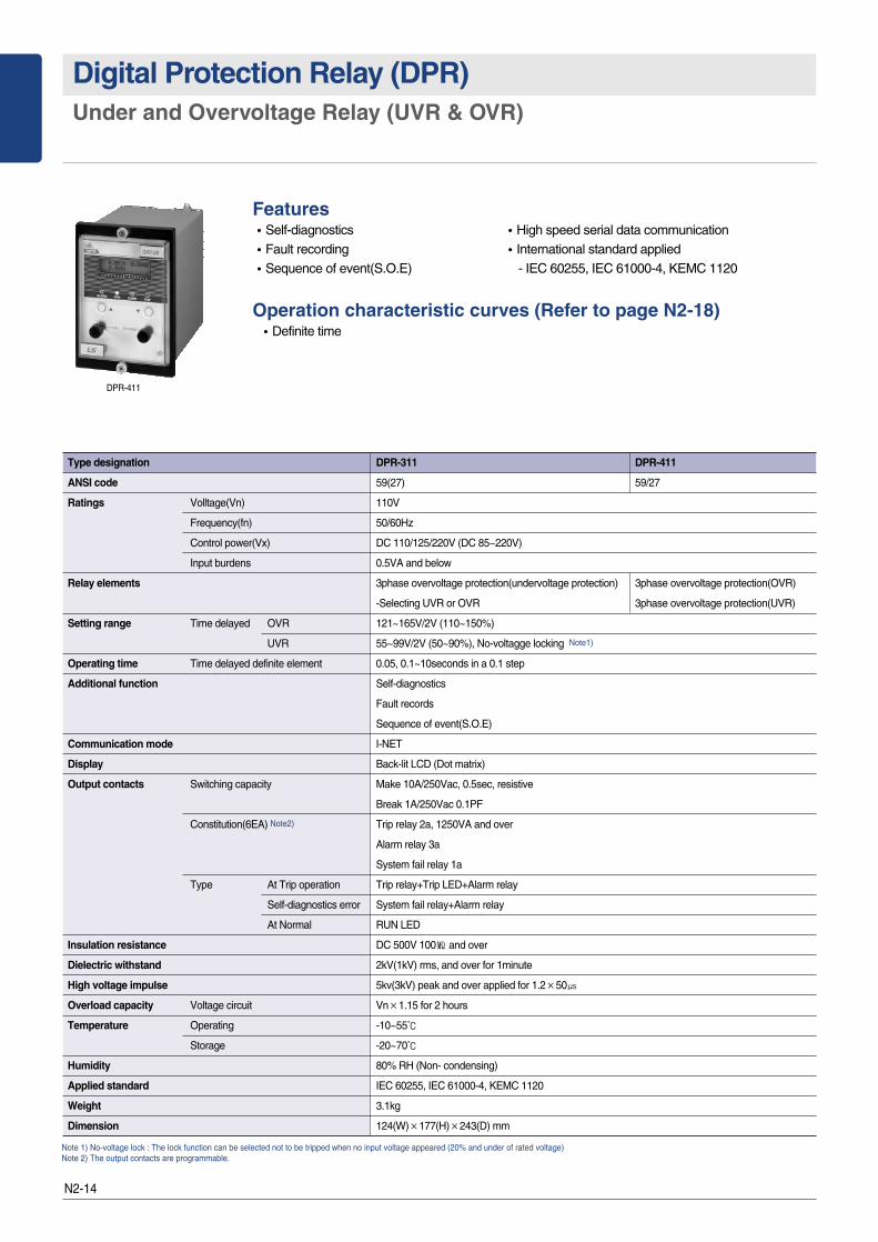
Digital Protection Relay (DPR)Under and Overvoltage Relay (UVR & OVR)
DPR-411
Type designation DPR-311 DPR-411
ANSI code 59(27) 59/27
Ratings Volltage(Vn) 110V
Frequency(fn) 50/60Hz
Control power(Vx) DC 110/125/220V (DC 85~220V)
Input burdens 0.5VA and below
Relay elements 3phase overvoltage protection(undervoltage protection) 3phase overvoltage protection(OVR)
-Selecting UVR or OVR 3phase overvoltage protection(UVR)
Setting range Time delayed OVR 121~165V/2V (110~150%)
UVR 55~99V/2V (50~90%), No-voltagge locking Note1)
Operating time Time delayed definite element 0.05, 0.1~10seconds in a 0.1 step
Additional function Self-diagnostics
Fault records
Sequence of event(S.O.E)
Communication mode I-NET
Display Back-lit LCD (Dot matrix)
Output contacts Switching capacity Make 10A/250Vac, 0.5sec, resistive
Break 1A/250Vac 0.1PF
Constitution(6EA) Note2) Trip relay 2a, 1250VA and over
Alarm relay 3a
System fail relay 1a
Type At Trip operation Trip relay+Trip LED+Alarm relay
Self-diagnostics error System fail relay+Alarm relay
At Normal RUN LED
Insulation resistance DC 500V 100㏁ and over
Dielectric withstand 2kV(1kV) rms, and over for 1minute
High voltage impulse 5kv(3kV) peak and over applied for 1.2×50㎲
Overload capacity Voltage circuit Vn×1.15 for 2 hours
Temperature Operating -10~55℃
Storage -20~70℃
Humidity 80% RH (Non- condensing)
Applied standard IEC 60255, IEC 61000-4, KEMC 1120
Weight 3.1kg
Dimension 124(W)×177(H)×243(D) mm
Note 1) No-voltage lock : The lock function can be selected not to be tripped when no input voltage appeared (20% and under of rated voltage)Note 2) The output contacts are programmable.
Features�Self-diagnostics �High speed serial data communication�Fault recording �International standard applied�Sequence of event(S.O.E) - IEC 60255, IEC 61000-4, KEMC 1120
Operation characteristic curves (Refer to page N2-18)�Definite time
N2-15
DP
R
N2
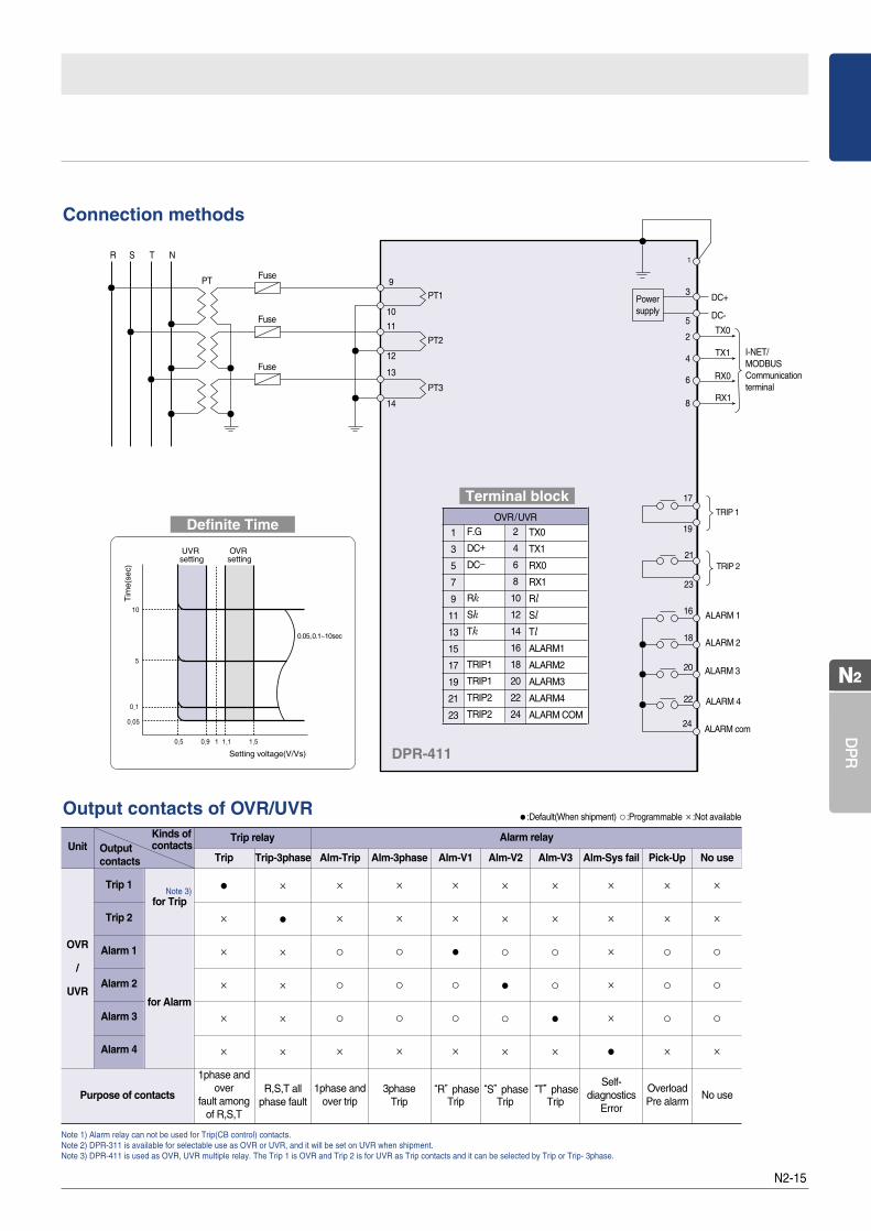
Note 1) Alarm relay can not be used for Trip(CB control) contacts.Note 2) DPR-311 is available for selectable use as OVR or UVR, and it will be set on UVR when shipment.Note 3) DPR-411 is used as OVR, UVR multiple relay. The Trip 1 is OVR and Trip 2 is for UVR as Trip contacts and it can be selected by Trip or Trip- 3phase.
DPR-411
1
3
5
7
9
11
13
15
17
19
21
23
2
4
6
8
10
12
14
16
18
20
22
24
OVR/UVRF.G
DC+
DC_
Rk
Sk
Tk
TRIP1
TRIP1
TRIP2
TRIP2
TX0
TX1
RX0
RX1
Rl
Sl
Tl
ALARM1
ALARM2
ALARM3
ALARM4
ALARM COM
Terminal block
Definite Time
Connection methods
Output contacts of OVR/UVR
Trip 1
Trip 2
Alarm 1
Alarm 2
Alarm 3
Alarm 4
Unit
OVR
/
UVR
for TripNote 3) ●
×
×
×
×
×
×
●
×
×
×
×
×
×
○
○
○
×
×
×
○
○
○
×
×
×
●
○
○
×
×
×
○
●
○
×
×
×
○
○
●
×
×
×
×
×
×
●
×
×
○
○
○
×
×
×
○
○
○
×
for Alarm
Purpose of contacts “T”phaseTrip
“S”phaseTrip
“R”phaseTrip
3phaseTrip
1phase andover trip
R,S,T allphase fault
1phase andover
fault amongof R,S,T
Self-diagnostics
Error
OverloadPre alarm
No use
●:Default(When shipment) ○:Programmable ×:Not available
Kinds ofcontacts
Trip Trip-3phase Alm-Trip Alm-3phase Alm-V1 Alm-V2 Alm-V3 Alm-Sys fail Pick-Up No useOutputcontacts
Trip relay Alarm relay
N2-16
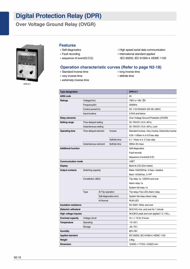
Digital Protection Relay (DPR)Over Voltage Ground Relay (OVGR)
DPR-511
Features�Self-diagnostics �High speed serial data communication�Fault recording �International standard applied �sequence of event(S.O.E) -IEC 60255, IEC 61000-4, KEMC 1120
Operation characteristic curves (Refer to page N2-18)�Standard inverse time �long inverse time�very inverse time �definite time �extremely inverse time
Type designation DPR-511
ANSI code 64
Ratings Voltage(Von) 190V or 190/ 3V
Frequency(fn) 50/60Hz
Control power(Vx) DC 110/125/220V (DC 85~220V)
Input burdens 0.5VA and below
Relay elements Over Voltage Ground Protection (OVGR)
Setting range Time delayed setting 20~76V/2V (10.5~40%)
Instantaneous setting 20~76V/2V (10.5~40%), Lock
Operating time Time delayed element Inverse Standard inverse, Very inverse, Extremely inverse
0.05~1.00sec in a 0.01sec step
Definite time 0.1~10sec in a 0.1sec step
Instantaneous element Definite time Within 35 msec
Additional function Self-diagnostics
Fault records
Sequence of event(S.O.E)
Communication mode I-NET
Display Back-lit LCD (Dot matrix)
Output contacts Switching capacity Make 10A/250Vac, 0.5sec, resistive
Back 1A/250Vac, 0.1PF
Constitution (3EA) Trip relay 1a, 1250VA and over
Alarm relay 1a
System fail relay 1a
Type At Trip operation Trip relay+Trip LED+Alarm relay
Self-diagnostics error System fail relay+Alarm relay
At Normal RUN LED
Insulation resistance DC 500V 100㏁ and over
Dielectric withstand 2kV(1kV) rms. and over for 1 minute
High voltage impulse 5kV(3kV) peak and over applied 1.2×50㎲
Overload capacity Voltage circuit Vn×1.15 for 3 hours
Temperature Operating -10~55℃
Storage -20~70℃
Humidity 80% RH
Applied standard IEC 60255, IEC 61000-4, KEMC 1120
Weight 2.8kg
Dimension 124(W)×177(H)×243(D) mm
√
N2-17
DP
R
N2
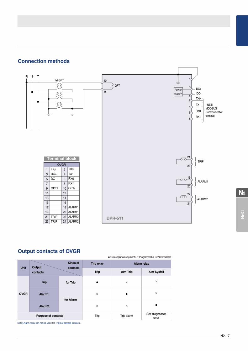
Note) Alarm relay can not be used for Trip(CB control) contacts.
1
3
5
7
9
11
13
15
17
19
21
23
2
4
6
8
10
12
14
16
18
20
22
24
OVGR
F.G
DC+
DC_
GPTk
TRIP
TRIP
TX0
TX1
RX0
RX1
GPTl
ALARM1
ALARM1
ALARM2
ALARM2
Terminal block
Connection methods
Output contacts of OVGR
DPR-511
Purpose of contacts
Alarm relay
Self-diagnosticserror
Trip alarm
Alm-SysfailAlm-Trip
Trip relay
for Trip
for Alarm
Trip
Trip
Unit
OVGR
Trip
Alarm1
Alarm2
●
×
×
×
●
×
×
×
●
Kinds of
contacts Output
contacts
●:Default(When shipment) ○:Programmable ×:Not available
N2-18
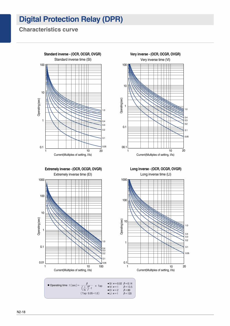
Digital Protection Relay (DPR)Characteristics curve
Standard inverse - (OCR, OCGR, OVGR)Standard inverse time (SI)
Current(Multiples of setting, I/Is)
Very inverse time (VI)
Extremely inverse time (EI) Long inverse time (LI)
Very inverse - (OCR, OCGR, OVGR)
Extremely inverse - (OCR, OCGR, OVGR) Long inverse - (OCR, OCGR, OVGR)
10
0.1101 20
0.05
0.2
0.3
0.4
1.0
Ope
ratin
g(se
c)
100
0.1
Current(Multiples of setting, I/Is)
1000
100
10
1
0.1
0.0110 1001
0.05
0.20.30.4
1.0
Ope
ratin
g(se
c)
0.1
Current(Multiples of setting, I/Is)
1000
100
10
0.1
1
10 201
0.05
0.2
0.30.4
1.0
Ope
ratin
g(se
c)
0.1
Current(Multiples of setting, I/Is)
10
1
00.1
0.1
101 20
0.05
0.2
0.30.4
1.0
Ope
ratin
g(se
c)
0.1
100
1
Cut-out dimension
N2-19
DP
R
N2
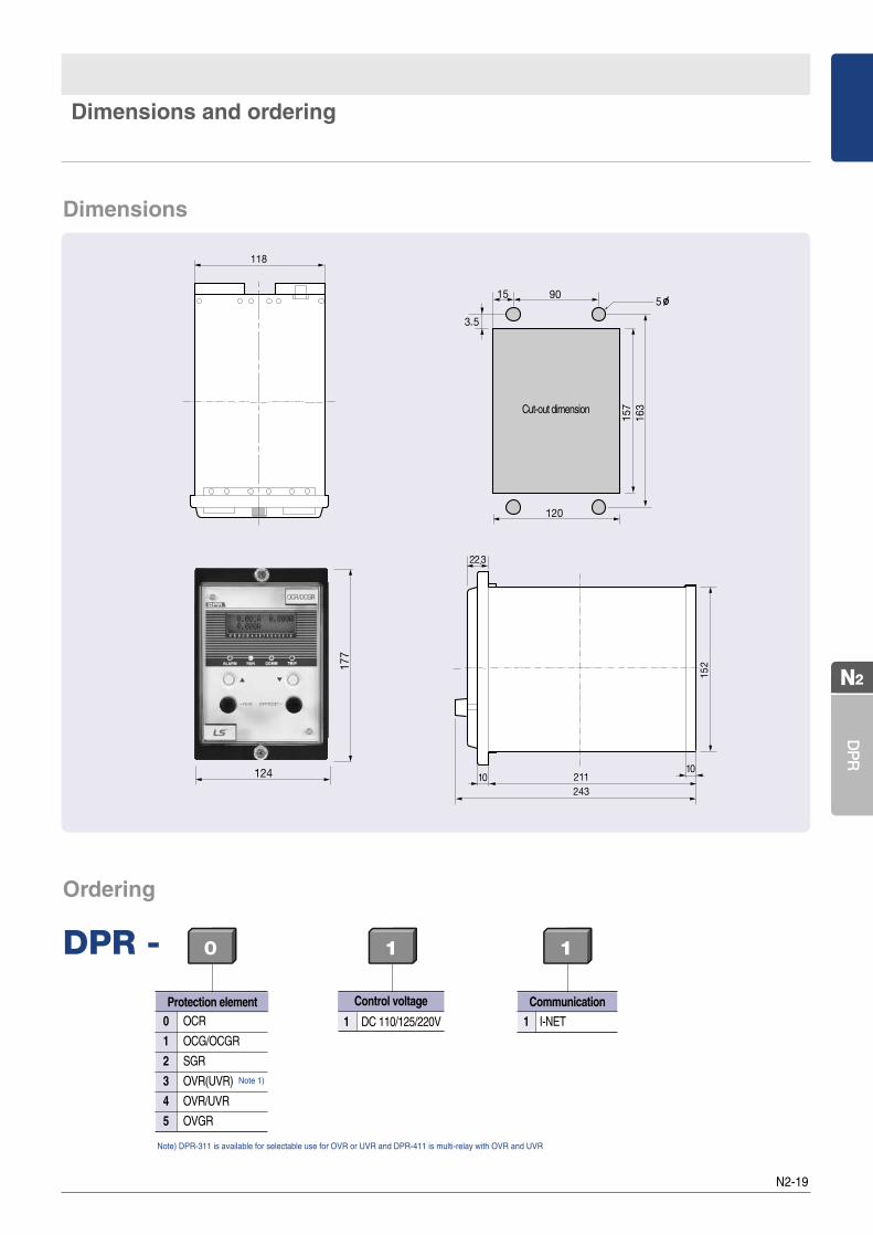
Dimensions and ordering
Dimensions
Note) DPR-311 is available for selectable use for OVR or UVR and DPR-411 is multi-relay with OVR and UVR
Protection element0 OCR
1 OCG/OCGR
2 SGR
3 OVR(UVR)
4 OVR/UVR
5 OVGR
Note 1)
Ordering
DPR - 0 1 1
1 DC 110/125/220V
Control voltage
1 I-NET
Communication