
Dottorato di Ricerca in Ingegneria Informatica XXI Ciclo ...mdeleoni/documenti/PhDthesis.pdf · a...
234
Sapienza - Universit ` a di Roma Dottorato di Ricerca in Ingegneria Informatica XXI Ciclo – 2009 Adaptive Process Management in Highly Dynamic and Pervasive Scenarios Massimiliano de Leoni
Transcript of Dottorato di Ricerca in Ingegneria Informatica XXI Ciclo ...mdeleoni/documenti/PhDthesis.pdf · a...
Sapienza - Universita di Roma
Dottorato di Ricerca in Ingegneria Informatica
XXI Ciclo – 2009
Adaptive Process Management
in Highly Dynamic and Pervasive Scenarios
Massimiliano de Leoni


Sapienza - Universita di Roma
Dottorato di Ricerca in Ingegneria Informatica
XXI Ciclo - 2009
Massimiliano de Leoni
Adaptive Process Management
in Highly Dynamic and Pervasive Scenarios
Thesis Committee
Prof. Tiziana CatarciProf. Giuseppe De GiacomoDr. Massimo Mecella
Reviewers
Dr. Alfredo GabaldonProf. Jan Mendling

Author’s address:
Massimiliano de LeoniDipartimento di Informatica e Sistemistica Antonio RubertiSapienza Universita di RomaVia Ariosto 25, I-00185 Roma, Italye-mail: [email protected]: http://www.dis.uniroma1.it/∼deleoni

Ringraziamenti
Ora che questa tesi e completata ed un altro passo della mia vita e statafatto, non posso non tornare indietro e ripercorre tutti questi anni da quando,appena laureato di 1◦ livello, la Prof. Catarci mi propose come assistente alladidattica al Dr. Mecella. Dissi di sı, e da allora inizio questa avventura...Quindi non posso che dare un sentito ringraziamento alla Prof. Catarci, cheha permesso che tutto questo avesse inizio e continuasse fino ad oggi. Correval’anno 2003 e allora comincio la collaborazione, sebbene inizialmente solamenteper la didattica.
Un immenso ringraziamento va al Dr. Massimo Mecella. Senza Massimonon avrei mai potuto scrivere questa tesi e crescere umanamente e profession-almente cosı tanto. Massimo e stato piu di quello che il suo ruolo lo avrebbeportato a fare.. E’ stato anche un amico, e un supporto nei momenti di scon-forto durante tutti gli anni da dottorando. Grazie! Grazie! Grazie!
Molti ringraziamenti vanno anche a Prof. De Giacomo, per il suo scien-tifico supporto e per il tempo che mi ha dedicato; egli e stato un prezioso men-tore di molti degli aspetti toccati in questa tesi. Desidero inoltre ringraziareDr. Sardina, una persona umanamente veramente squisita, che e stato moltodisponibile e pronto ad aiutarmi quando c’era da realizzare concretamente letecniche sviluppate in questa tesi. Senza di lui, SmartPM non sarebbe statomai realizzato.
Inoltre, non posso non esprimere la mia gratitudine al Prof. ter Hofstedeche mi ha accolto per 6 mesi nel suo gruppo di ricerca e per il tempo chemi ha dedicato. Durante il purtroppo breve periodo passato lı, sono riuscitoa crescere professionalmente molto piu di quanto avrei sperato di fare. Unsaluto va anche all’Australia che mi e rimasta nel cuore e sara per sempre lamia seconda patria...
Molte grazie ai revisori esterni per i loro commenti sul contenuto e lapresentazione di questa dissertazione. Molte grazie a tutti i collaboratori e itesisti che sono stati di supporto negli anni nello sviluppo dei diversi aspetticonsiderati in questa tesi; un grosso abbraccio a tutti gli amici e a tutti icolleghi nel Dipartimento di Informatica e Sistemistica. Non voglio nominarenessuno in particolare per evitare che mi dimentichi di qualcun’altro, e non
v

sarebbe giusto..Inoltre voglio ringraziare Sara: ella ha iniziato avventura con me e mi ha
incoraggiato durante tutto il percorso; purtroppo il suo “ruolo” nel frattempoe cambiato per ragioni piu grandi di noi.
Desidero esprimere poi la mia riconoscenza ai miei genitori, Pierfrancescoe Maria Rosa, a mio fratello Fabrizio, che, nonostante non approvassero la miascelta, mi hanno comunque dato supporto e non mi hanno “messo il bastonetra le ruote”.
Per ultima, ma non per ordine di importanza, voglio ringraziare la miaamata Mariangela. Ella e arrivata da poco nella mia vita, ma quanto bastaper accenderne la luce, quella luce che piano piano si era spenta.

Acknowledgements
Now, that this thesis is completed and another step of my life has been walked,I cannot prevent myself from looking behind and going back over all these yearsfrom when, just bachelor graduated, Prof. Catarci proposed me to be teachingassistant to Dr. Mecella. I accepted, and from them this adventure began.Therefore, I wish to thank Prof. Catarci, who has allowed all of this to beginand keep still going on. It was year 2003 and my collaboration started, eventhough iniatially only for teaching purposes.
I need to thank Dr. Massimo Mecella infinitely: without him I could neverhave written this thesis, nor be growing up humanely and professionally somuch. Massimo has been more than his role would have led up to do... He hasbeen also a friend as well as and a support in the moments of discouragementduring the years of the Ph.D. program. Thanks! Thanks! Thanks so much!
I need to say “thanks” to Prof. De Giacomo, as well, for his scientificsupport and for the time he devoted me. He has been a precious mentor forthe topics touched on in thesis. I wish also to thank Dr. Sardina, a reallyexquisite person, who has been definitely promptly helpful when I had torealize concretely the techniques conceived in the thesis. Without him, I couldnever develop concretely SmartPM.
Moreover, I cannot prevent myself from expressing my gratitude to Prof.ter Hofstede, who hosted me in his research group, devoting a lot of his timeto me. During the (unfortunately) short time there, I could grow up muchmore than I hoped to do. A lovely hug is also for Australia, which is in myheart of hearts and will be forever my second country.
I wish to express my thanks to the external referees for their valuable com-ments on the content and the presentation of this dissertation. Thanks verymuch to all collaborators and Master/Bachelor students that have been con-tributing in the development of many practical aspects of this thesis; a lovelyhug to all of my friends and to my colleagues of Dipartimento di Informaticae Sistemistica. I am not willing to name explicitly anyone to avoid forgettingany, as that would not be fair.
Furthermore, I wish to thank Sara; she started this adventure with meand supported me along this path; unfortunately, her “role” has meanwhile
vii

changed for some reasons greater than us.I wish to show my appreciation to my parents, Pierfrancesco e Maria Rosa,
my brother Fabrizio, who all, although they were not approving my choice,supported me anyway “without throwing a spanner in the works”.
Last, but not least, I wish to thank my beloved Mariangela. She hasentered recently into my life, but enough to turn on its light, which little bylittle were going off.

Contents
1 Introduction 11.1 Problem Statement . . . . . . . . . . . . . . . . . . . . . . . . . 11.2 Original Contributions . . . . . . . . . . . . . . . . . . . . . . . 31.3 Publications and Collaborations . . . . . . . . . . . . . . . . . . 71.4 Outline of the Thesis . . . . . . . . . . . . . . . . . . . . . . . . 11
2 Rationale 13
3 Literature Review 193.1 Process Modelling Languages . . . . . . . . . . . . . . . . . . . 21
3.1.1 Workflow Nets . . . . . . . . . . . . . . . . . . . . . . . 213.1.2 Yet Another Workflow Language (YAWL) . . . . . . . . 253.1.3 Event-driven Process Chains (EPCs) . . . . . . . . . . . 263.1.4 π-calculus . . . . . . . . . . . . . . . . . . . . . . . . . . 273.1.5 Discussion . . . . . . . . . . . . . . . . . . . . . . . . . . 30
3.2 Related Works on Adaptability . . . . . . . . . . . . . . . . . . 333.3 Case Handling . . . . . . . . . . . . . . . . . . . . . . . . . . . 39
4 Framework for Automatic Adaptation 434.1 Preliminaries . . . . . . . . . . . . . . . . . . . . . . . . . . . . 454.2 Execution Monitoring . . . . . . . . . . . . . . . . . . . . . . . 494.3 Process Formalisation in Situation Calculus . . . . . . . . . . . 534.4 Monitoring Formalisation . . . . . . . . . . . . . . . . . . . . . 574.5 A Concrete Technique for Recovery . . . . . . . . . . . . . . . . 594.6 Summary . . . . . . . . . . . . . . . . . . . . . . . . . . . . . . 63
5 The SmartPM System 655.1 The IndiGolog Platform . . . . . . . . . . . . . . . . . . . . . . 66
5.1.1 The top-level main cycle and language semantics . . . . 675.1.2 The temporal projector . . . . . . . . . . . . . . . . . . 705.1.3 The environment manager and the device managers . . 715.1.4 The domain application . . . . . . . . . . . . . . . . . . 72
ix
5.2 The SmartPM Engine . . . . . . . . . . . . . . . . . . . . . . . 725.2.1 Coding processes by the IndiGolog interpreter . . . . . . 755.2.2 Coding the adaptation framework in IndiGolog . . . . . 835.2.3 Final discussion . . . . . . . . . . . . . . . . . . . . . . . 90
5.3 The Network Protocol . . . . . . . . . . . . . . . . . . . . . . . 925.3.1 Protocols and implementations . . . . . . . . . . . . . . 925.3.2 Testing Manets . . . . . . . . . . . . . . . . . . . . . . . 945.3.3 Final Remarks . . . . . . . . . . . . . . . . . . . . . . . 101
5.4 Disconnection Prediction in Manets . . . . . . . . . . . . . . . 1025.4.1 Related Work . . . . . . . . . . . . . . . . . . . . . . . . 1045.4.2 The Technique Proposed . . . . . . . . . . . . . . . . . . 1055.4.3 Technical Details . . . . . . . . . . . . . . . . . . . . . . 1125.4.4 Experiments . . . . . . . . . . . . . . . . . . . . . . . . 114
5.5 The OCTOPUS Virtual Environment . . . . . . . . . . . . . . 1165.5.1 Related Work . . . . . . . . . . . . . . . . . . . . . . . . 1185.5.2 Functionalities and Models . . . . . . . . . . . . . . . . 1205.5.3 The OCTOPUS Architecture . . . . . . . . . . . . . . . 125
5.6 Summary . . . . . . . . . . . . . . . . . . . . . . . . . . . . . . 126
6 Adaptation of Concurrent Branches 1296.1 General Framework . . . . . . . . . . . . . . . . . . . . . . . . . 1306.2 The adaptation technique . . . . . . . . . . . . . . . . . . . . . 131
6.2.1 Formalization . . . . . . . . . . . . . . . . . . . . . . . . 1316.2.2 Monitoring-Repairing Technique . . . . . . . . . . . . . 136
6.3 An Example from Emergency Management . . . . . . . . . . . 1426.4 A summary . . . . . . . . . . . . . . . . . . . . . . . . . . . . . 145
7 Some Covered Related Topics 1497.1 Automatic Workflow Composition . . . . . . . . . . . . . . . . 151
7.1.1 Conceptual Architecture . . . . . . . . . . . . . . . . . . 1527.1.2 A Case Study . . . . . . . . . . . . . . . . . . . . . . . . 1537.1.3 The Proposed Technique . . . . . . . . . . . . . . . . . . 1617.1.4 Final remarks . . . . . . . . . . . . . . . . . . . . . . . . 165
7.2 Visual Support for Work Assignment in PMS . . . . . . . . . . 1667.2.1 Related Work . . . . . . . . . . . . . . . . . . . . . . . . 1687.2.2 The General Framework . . . . . . . . . . . . . . . . . . 1697.2.3 Fundamentals . . . . . . . . . . . . . . . . . . . . . . . . 1717.2.4 Available Metrics . . . . . . . . . . . . . . . . . . . . . . 1727.2.5 Implementation . . . . . . . . . . . . . . . . . . . . . . . 1767.2.6 The YAWL system . . . . . . . . . . . . . . . . . . . . . 1777.2.7 The User Interface . . . . . . . . . . . . . . . . . . . . . 1787.2.8 Architectural Considerations . . . . . . . . . . . . . . . 180

7.2.9 Example: Emergency Management . . . . . . . . . . . . 1847.2.10 Final Remarks . . . . . . . . . . . . . . . . . . . . . . . 190
7.3 A summary . . . . . . . . . . . . . . . . . . . . . . . . . . . . . 191
8 Conclusion 193
A The Code of the Running Example 197


Chapter 1
Introduction
1.1 Problem Statement
Nowadays organisations are always trying to improve the performance of theprocesses they are part of. It does not matter whether such organisations aredealing with classical static business domains, such as loans, bank accountsor insurances, or with pervasive and highly dynamic scenarios. The demandsare always the same: seeking more efficiency for their processes to reduce thetime and the cost for their execution.
According to the definition given by the Workflow Management Coali-tion1, a workflow is “the computerised facilitation of automation of a businessprocess, in whole or part”. The Workflow Management Coalition defines aWorkflow Management System as “a system that completely defines, man-ages and executes workflows through the execution of software whose orderof execution is driven by a computer representation of the workflow logic”.Workflow Management Systems (WfMSs) are also known as Process Manage-ment Systems (PMSs), and we are going to use both of them interchangeablythroughout this thesis. Accordingly, this thesis uses many times word “pro-cess” is place of word “workflow”, although the original acceptation of theformer is not intrinsically referring to its computerised automation.
The idea of Process Management Systems as information systems alignedin a process-oriented way was born in late 80’s with the aim of improving theprocess performances. And PMSs are still growing in importance since thedemand of efficiency and effectiveness is more and more crucial in a highlycompetitive world.
PMSs improve efficiency, while providing a better process control [46, 136].The use of computer systems avoids process executions to be improvised andguarantees a more systematic process execution, which finally translates to an
1http://wfmc.org
1

2 CHAPTER 1. INTRODUCTION
overall improvement of the response time.In this thesis we are not dealing with classical business scenarios, which it
has been extensively researched on, but we turn our attention to highly dy-namic and pervasive scenarios. In pervasive scenarios, information processingis thoroughly integrated with the physical environment and its objects. Assuch, people cannot carried out activities remotely, but they need to interactactively with the environment and make physical changes to it. Pervasive sce-narios comprise, for instance, emergency management, health care or homeautomation (a.k.a. domotics). The physical interaction with the environmentincreases the frequency of unexpected contingencies with respect to classicalscenarios. Being pervasive scenarios very dynamic and turbulent, PMSs shouldprovide a higher degree of operational flexibility/adaptability to suit them.
According to Andresen and Gronau [3] adaptability can be seen as anability to change something to fit to occurring changes. Adaptability is to beunderstood here as the ability of a PMS to adapt/modify processes efficientlyand fast to changed circumstances. If processes were not adapted, they couldnot be carry out in the changed environment.
In pervasive settings, efficiency and effectiveness when carrying on pro-cesses are a strong requirement. For instance, in emergency management sav-ing minutes could result in saving injured people, preventing buildings fromcollapses, and so on. Or, pervasive health-care processes can cause people’spermanent diseases when not executed by given deadlines. In order to im-prove effectiveness of process execution, adaptation ought to be as automaticas possible and to require minimum manual human intervention. Indeed, hu-man intervention would cause delays, which might not be acceptable.
The main concern of this thesis is to research for improving the degreeof automatic adaptation to react to very frequent changes in the executionenvironment and fit processes accordingly.
Let us consider a scenario for emergency management where processesshow typical a complexity that is comparable to business settings. Therefore,it worthy using a PMS to coordinate the activities of emergency operatorswithin teams. The members of a team are equipped with PDAs and are coor-dinated through the PMS residing on a leader device (usually an ultra-mobilelaptop). In such a PMS, process schemas (in the form of enriched ActivityDiagrams) are defined, describing different aspects, such as tasks/activities,control and data flow, tasks assignment to services, etc. Every task is associ-ated to a set of conditions which ought to be true for the task to be performed;conditions are defined on the control and data flow (e.g., a previous task hasto be completed or a variable needs to be assigned a specific range of values).Devices communicate with each other through ad hoc networks. A Mobile Adhoc NETwork (manet) is a P2P network of mobile nodes capable of com-municating with each other without an underlying infrastructure. Nodes can

1.2. ORIGINAL CONTRIBUTIONS 3
communicate with their own neighbors (i.e., nodes in radio-range) directly bywireless links. Non-neighbor nodes can communicate as well, by using otherintermediate nodes as relays that forward packets toward destinations. Thelack of a fixed infrastructure makes this kind of network suitable in all scenar-ios where it is needed to deploy quickly a network, but the presence of accesspoints is not guaranteed, as in emergency management [91].
The execution of the emergency management process requires such devicesto be continually connected to the PMS. However, this cannot be guaranteed:the environment is highly dynamic and the movement of nodes (that is, devicesand related operators) within the affected area, while carrying out assignedtasks, can cause disconnections and, thus, unavailability of nodes. From thecollection of actual user requirements [35, 66, 67], it results that typical teamsare formed by a few nodes (less than 10 units), and therefore frequently a sim-ple task reassignment is not feasible. Indeed, there may not be two “similar”services available to perform a given task.
Adaptability might consist in this case to recover the disconnection of anode X, and that can be achieved by assigning a task “Follow X” to anothernode Y in order to maintain the connection. When the connection has beenrestored, the process can progress again.
1.2 Original Contributions
The definitions of adaptability currently available in literature are too genericfor our intends. This thesis comes up with a more precise definition of processadaptability which stems from the the field of robotics and agent program-ming [31] and is adapted for process management.
Adaptability can be seen as the ability of the PMS to reduce the gap ofthe virtual reality, the (idealized) model of reality that is used by the PMS todeliberate, from the physical reality, the real world with the actual values ofconditions and outcomes. For instance in the aforementioned scenario aboutemergency management, in virtual reality PMS assumes nodes to be alwaysconnected. But in physical reality when nodes are moving, they can lose awireless connection and, hence, may be unable to communicate.
The reduction of this gap requires sufficient knowledge of both kinds ofrealities (virtual and physical). Such knowledge, harvested by the servicesperforming the process tasks, would allow the PMS to sense deviations and todeal with their mitigation.
In theory there are three possibilities to deal with deviations:
1. Ignoring deviations – this is, of course, not feasible in general, since thenew situation might be such that the PMS is no more able to carry outthe process instance.

4 CHAPTER 1. INTRODUCTION
2. Anticipating all possible discrepancies – the idea is to include in theprocess schema the actions to cope with each of such failures. This canbe seen as a try-catch approach, used in some programming languagessuch as Java. The process is defined as if exogenous actions cannot occur,that is everything runs fine (the try block). Then, for each possibleexogenous event, a catch block is designed in which the method is givento handle the corresponding exogenous event. As already touched onand widely discussed in Chapter 3, most PMSs use this approach. Forsimple and mainly static processes, this is feasible and valuable; but,especially in mobile and highly dynamic scenarios, it is quite impossibleto take into account all exception cases.
3. Devising a general recovery method able to handle any kind of exogenousevents – considering again the metaphor of try/catch, there exists justone catch block, able to handle any exogenous events, included theunexpected. The catch block activates the general recovery method tomodify the old process P in a process P ′ so that P ′ can terminate in thenew environment and its goals are included in those of P . This approachrelies on the execution monitor (i.e., the module intended for executionmonitoring) that detects discrepancies leading the process instance notto be terminable. When they are sensed, the control flow moves to thecatch block. An important challenge here is to build the monitor whichis able to identify which exogenous events are relevant, i.e. that preventprocesses from being completed successfully, as well as to automaticallysynthesize P ′ during the execution itself.
This thesis aims at achieving adaptability by using the third approach,which seems to be the most appropriate when dealing with scenarios wherethe frequency of unexpected exogenous events are relatively high.
After an investigation of possible techniques which can be used for auto-matically adaptation, we focussed our attention to well-established techniquesand frameworks in Artificial Intelligence, such as Situation Calculus [119] andautomatic planning. Those techniques were born to coordinate robots andintelligent agents, i.e. in application fields that are far from the main topic ofthis thesis. Therefore, their applicability to process management has requireda significant effort in terms of conceptualisation and formalisation. Then, wehave proposed a proof-of-concept implementation, namely SmartPM, whichis based on the IndiGolog interpreter developed at University of Toronto andRMIT University, Melbourne. The use of an available platform born for co-ordinating robots has raised critical issues when used to integrate generic au-tomatic services and humans. And solving these issues has required a tightcollaboration with the conceivers and developers.
1.2. ORIGINAL CONTRIBUTIONS 5
Actions are modeled in IndiGolog [121], a logic-based language used forrobot and agent programming. Fluents denoting world properties of inter-est are modeled in SitCalc as well as pre- and post-conditions of actionsare. Such formalisms enable to reason over exogenous events and determine(i) when such events are able to invalidate the execution of certain processesand (ii) how to recovery from them and take the original process back to theright track. Specifically, when a certain deviation is sensed that makes deviatethe physical reality from the virtual one, we make use of planning mechanismsto find and enact a set of activities thus recovering from such a mismatching.
The first framework proposed is able to deal with any well-structure pro-cesses with no restrictions (see Chapter 4). Then, we have later a secondframework that, from the one side, is more efficient. But, from the otherside, it poses some restrictions on the structure and the characteristics of theprocesses and, hence, it cannot be always used (see Chapter 6).
In sum, the contribution of this thesis to the field of automatic processadaptability is manifold:2
• The collection of actual requirements by users acting in such pervasiveand dynamic scenarios. Requirement collections guarantee that the re-sulting system is really useful for end users [66, 67, 23, 22, 35, 24].
• The analysis of existing work within the topic of adaptability (a.k.a.flexibility), exception handling and process modelling in order to analyzeand systematize available modelling languages and approaches to processadaptability.
• The evaluation of possible alternative approaches. We tried other ap-proaches which are valuable but partly fail when dealing with unexpecteddeviations. Finally, we move beyond the borders of the process manage-ment field, yielding to agent and robotic programming. By such analysisand evaluation, we have been also able to give a precise characterizationof the notion of process adaptability in term of gap between the virtualand physical reality [36, 7, 34].
• The conceptualisation and formalisation of a first set of techniques forautomatic adaptation of any well-structured process [37]. In order toachieve that, we provide some sub-contribution:
– The definition of a precise semantic for defining formally the pro-cess structure and the activity conditions. These semantics hasbeen obtained tailoring Situation Calculus and IndiGolog to processmanagement. Formalising processes using Situation Calculus and
2The references below concern papers of the candidate addressing such topics

6 CHAPTER 1. INTRODUCTION
IndiGolog has required a significant effort, since such formalisms arenot intended for that.
– The formalization of the concept of equivalence of two processesthrough bisimulation. A process P running in an environment E issaid to be equivalent to a process P ′ running in an environment E′
if P achieves the same goals as P ′ when P is executed in E and P ′
in E′.– The effort of taking the adaptability issue to the problem of find-
ing a plan to recover from discrepancies in order to eliminate themismatching between the physical and the virtual reality.
– The formal proof of the correctness and completeness of the pro-posed approach.
• The development of SmartPM, a proof-of-concept implementation of theadaptation framework that is based on the IndiGolog interpreter devel-oped at University of Toronto and RMIT University, Melbourne [39].The use of a platform specifically intended for robot and agent program-ming has required a tight collaboration with the conceivers and develop-ers to tailor it to process management. The aim of such an implementa-tion has been to demonstrate the practical feasibility and effectiveness ofthe approach beyond the formal proof of soundness. For the sake of test-ing in a context of mobile ad-hoc networks, we have provided also othercontributes, specifically to the field of mobile networking. Specifically:
– The conception and development of a proper manet emulator,namely octopus, which overtakes some issues significant in ourtesting. Section 5.5 describes octopus and motivates its concep-tion. [28]
– The development of a proper manet layer that is really working onlow-profile devices. Many implementations are in theory availablebut, in fact, either they do not work on low-profile or they arepartially fledged (see Section 5.3). [14]
– The development of some sensors able to sense deviations. Specif-ically, we have developed a module that is able to predict nodedisconnections before they actually happen. [38, 41]
• The conception of a second technique which aims at overcoming someof limitations of the first framework. It results to be more efficient indealing with recovery plans since it is able to stick individually the partswhich are affected by discrepancies without having to block the wholeprocess. On the other hand, this approach is applicable over more restric-tive conditions of the structured and the characteristic of processes. [33]

1.3. PUBLICATIONS AND COLLABORATIONS 7
We have also contributed on other topics of the field of process manage-ment, more in general. These topics address other challenging issues concern-ing pervasive scenarios. Specifically:
• The formalisation of a first step towards distributing the process orches-tration among the different devices of the involved services/participantsas well as towards synthesizing the process specification on the basis ofavailable services. Indeed, in pervasive scenarios any device may falldown in any moment because of the environment, including the devicehosting the engine. The sole way to avoid the engine to be a single pointof failure is to distribute the orchestration and the coordination amongall available devices. In addition, processes often might be only providedas template and their concrete instance are created when on the basis ofthe available services the process has to be enacted [53].
• The conceptualisation and the implementation of an innovative “client”tool to distribute tasks to process participants in a way they are aidedwhen choosing the next task to work on. This tool aims to overcomecurrent limitations of worklist handlers of the state-of-the-art in Process-aware Information Systems. These worklist handlers typically show asorted list of work items comparable to the way that e-mails are shown inmail agents. Since the worklist handler is the dominant interface betweenthe system and its users, it is worthwhile to provide a more advancedgraphical interface that uses information about work items and users aswell as about process cases which are completed or still running. Theworklist handler proposed aims to provide process participants with adeeper insight in the context in which processes are carried out. Thisway, participants can be assisted with the selection of the next workitem to perform. The approach uses the ”map metaphor” to visualisework items and resources (e.g., participants) in a sophisticated manner.Moreover, depending on the ”distance notion” chosen, work items arevisualised differently. For example, urgent work items of a type that suitsthe user are highlighted. The underlying map and distance notions maybe of a geographical nature (e.g., a map of a city or an office building),but may also be based on the process design, organisational structures,social networks, due dates, calenders, etc. [42]
1.3 Publications and Collaborations
The following publications have been produced while researching this thesis:
• M. de Leoni, F. De Rosa, M. Mecella“MOBIDIS: A Pervasive Architecture for Emergency”
8 CHAPTER 1. INTRODUCTION
In Proceedings of the 15th IEEE International Workshops on Enabling Tech-nologies: Infrastructures for Collaborative Enterprises (WETICE 2006), Uni-versity of Manchester, UK, June 26th -28th, 2006. AWARDED AS “BESTPAPER” OF DMC 2006 WORKSHOP.
• T. Catarci, M. de Leoni, M. Mecella, M. Angelaccio, S. Dustdar etal.“WORKPAD: 2-Layered Peer-to-Peer for Emergency Management throughAdaptive Processes”
In Proceedings of The 2nd International IEEE Conference on CollaborativeComputing: Networking, Applications and Worksharing (COLLABORATE-COM 2006), Atlanta, Georgia, USA, November 17th - 20th, 2006.
• M. de Leoni, A. Marrella, F. De Rosa, M. Mecella, A. Poggi, A.Krek, F. Manti“Emergency Management: from User Requirements to a Flexible P2P Archi-tecture”
In Proceedings of the 4th International Conference on Information Systems forCrisis Response and Management (ISCRAM’07 ), Delft, the Netherlands, May13th-16th, 2007.
• F. D’Aprano, M. de Leoni, M. Mecella“Emulating Mobile Ad-hoc Networks of Hand-held Devices. The OCTOPUSVirtual Environment”
In Proceedings of the ACM Workshop on System Evaluation for Mobile Plat-form: Metrics, Methods, Tools and Platforms (MobiEval) co-located with Mo-bisys 2007, Puerto Rico 11-14 June 2007
• M. de Leoni, M. Mecella, R. Russo“A Bayesian Approach for Disconnection Management”
In Proceedings of the 16th IEEE International Workshops on EnablingTechnologies: Infrastructures for Collaborative Enterprises (WETICE-2007),GET/INT, Paris, France, June 18-20, 2007
• T. Catarci, M. de Leoni, M. Mecella, S. Dustdar, L. Juszczyk et al.”The WORKPAD P2P Service-Oriented Infrastructure for Emergency Man-agement”
In Proceedings of the 16th IEEE International Workshops on EnablingTechnologies: Infrastructures for Collaborative Enterprises (WETICE 2007),GET/INT, Paris, France, June 18-20, 2007
• G. De Giacomo, M. de Leoni, M. Mecella, F. Patrizi“Automatic Workflow Composition of Mobile Services”
In Proceedings of the IEEE International Conference on Web Services (ICWS2007 ), Salt Lake City, USA, July, 2007.
• M. de Leoni, M. Mecella, G. De Giacomo“Highly Dynamic Adaptation in Process Management Systems through Execu-tion Monitoring”

1.3. PUBLICATIONS AND COLLABORATIONS 9
In Proceedings of the 5th International Conference on Business Process Man-agement (BPM 2007 ), Brisbane, Australia, 24-28 September 2007.
• M. de Leoni, F. De Rosa, M. Mecella, S. Dustdar“Resource Disconnection Management in MANET Driven by Process TimePlan”In Proceedings of the First International ACM Conference on Autonomic Com-puting and Communication Systems (AUTONOMICS’07 ), Rome, Italy, 28-30October 2007.
• T. Catarci, M. de Leoni, M. Mecella, G. Vetere, S. Dustdar et al.”Pervasive and Peer-to-Peer Software Environments for Supporting DisasterResponses”.“IEEE Internet Computing” Journal – Special Issue on Crisis Management -January 2008
• M. de Leoni, S. R. Humayoun, M. Mecella, R. Russo”A Bayesian Approach for Disconnection Management in Mobile Ad-hoc Net-work””Ubiquitous Computing and Communication” Journal - March 2008
• G. Bertelli, M. de Leoni, M. Mecella, J. DeanMobile Ad hoc Networks for Collaborative and Mission-critical Mobile Scenar-ios: a Practical StudyIn Proceedings of the 17th IEEE International Workshops on Enabling Tech-nologies: Infrastructures for Collaborative Enterprises (WETICE 2008), 23-25June 2008,Rome, Italy.
• M. de Leoni, A. Marrella, M. Mecella, S. Valentini, S. Sardina”Coordinating Mobile Actors in Pervasive and Mobile Scenarios: An AI-basedApproach”In Proceedings of the 17th IEEE International Workshops on Enabling Tech-nologies: Infrastructures for Collaborative Enterprises (WETICE 2008), 23-25June 2008,Rome, Italy.
• M. de Leoni, W. M. P. van der Aalst, A.H.M. ter Hofstede”Visual Support for Work Assignment in Process-aware Information Systems”In Proceedings of the 6th International Conference on Business Process Man-agement (BPM 2008 ), Milan, Italy, 1-4 September 2008.
• T. Catarci, F. Cincotti, M. de Leoni, M. Mecella, G. Santucci”Smart Homes for All: Collaborating Services in a for-All Architecture forDomotics”In Proceedings of the 4th International Conference on Collaborative Com-puting: Networking, Applications and Worksharing (CollaborateCom’08 ), Or-lando, USA, 13-16 November 2008
• D. Battista, A. De Gaetanis, M. de Leoni et al.”ROME4EU: A Web Service-based Process-aware Information System forSmart devices”

10 CHAPTER 1. INTRODUCTION
In Proceedings of the International Conference on Service Oriented Computing(ICSOC 2008 ), Sydney, Australia, 1-4 December 2008.
• M. de Leoni, Y. Lesperance, G. De Giacomo, M. Mecella”On-line Adaptation of Sequential Mobile Processes Running Concurrently”In Proceedings of the 24th ACM Symposium on Applied Computing (SAC09 )8-12 March, 2009, Honolulu, Hawaii, USA. Special Track ”Coordination Models,Languages and Applications”
• S. R. Humayoun, T. Catarci, M. de Leoni, A. Marrella, M. Mecella,M. Bortenschlager, R. Steinmann”Designing Mobile Systems in Highly Dynamic Scenarios. The WORKPADMethodology.”Springer’s International Journal on Knowledge, Technology & Policy, Volume22, Number 1 / March, 2009.
• S. R. Humayoun, T. Catarci, M. de Leoni, A. Marrella, M. Mecella,M. Bortenschlager, R. Steinmann”The WORKPAD User Interface and Methodology: Developing Smart and Ef-fective Mobile Applications for Emergency Operators”In Proceedings of 13th International Conference on Human-Computer Inter-action (HCI International 2009 ), 19-24 July, 2009, San Diego, USA. Session“Designing for Mobile Computing”.
• F. Cardi, M. de Leoni, M. Adams, W. M. P. van der Aalst, A.H.M.ter HofstedeVisual Support for Work Assignment in YAWLIn Proceedings of the Demonstration Track of 7th International Conference onBusiness Process Management (BPM 2009), September 2009, Ulm, Germany.To appear.
The work described in Section 7.2 has been mostly produced during aninternship of Mr. Massimiliano de Leoni at the BPM Group of the Facultyof Information Technology of Queensland University of Technology, Brisbane(Australia). His visit commenced on September 17th, 2007 and ceased onApril 07th, 2008 and was supervised by Prof. Arthur H. M. ter Hofstede,co-leader of this group.
The implementation of the adaptation framework has been developed incooperation with Dr. Sebastian Sardina, research assistant at the Agent Groupof the RMIT University, Melboune, Australia. In particular, Mr. de Leoni wasvisiting the group from December 7th, 2008 to December 17th, 2008, with theaim of solving the last details of the proof-of-concept implementation.
Mr. Massimiliano de Leoni has also co-chaired a workshop on ProcessManagement for Highly Dynamic and Pervasive Scenarios (PM4HDPS) heldin Milan on September 1st, 2008 in conjunction with the 6th International Con-ference on Business Process Management (BPM’08).3 The workshop aimed at
3Web site: http://pm4hdps.deleoni.it

1.4. OUTLINE OF THE THESIS 11
Figure 1.1: Outline of the Thesis and relationship among Chapters
providing a forum to draw attention to Highly Dynamic and Pervasive settingsand to exchange the latest individual research and development ideas. Thevaluable outcomes are summarized in [37].
1.4 Outline of the Thesis
Figure 1.1 diagrams the structure of this Thesis document. Specifically:
• Chapter 2 illustrates in detail the rationale behind the need of the newapproach to process adaptability that this Thesis deals with. In par-ticular, it highlights why the approaches currently proposed fail whendealing with Highly Dynamic and Pervasive Scenarios.
• Chapter 3 surveys the literature and describes the works, the systemsand the techniques that have been already proposed in the field of processadaptation. Specifically, it compares the choice of IndiGolog as modellinglanguage with respect to the other languages that are nowadays used byvarious Process Management Systems. Moreover, it discusses the levelsof support for process adaptability/flexibility and exception handlingin several of the leading commercial products and in some academic

12 CHAPTER 1. INTRODUCTION
prototypes. Finally, it concludes stating the inappropriateness of CaseHandling as approach to manage the performance of pervasive processes.
• Chapter 4 shows a first approach to handle unexpected exogenous events,and to recovery process instance executions when exogenous events makeimpossible their termination.
• Chapter 5 describes the most salient points of the concrete implemen-tation based on the IndiGolog platform developed by the University ofToronto and RMIT University.
• Chapter 6 illustrates a more efficient adaptability technique but undermore restrictive conditions with respect to the one proposed in Chap-ter 4.
• Chapter 7 introduces some research topics related to the process man-agement in pervasive scenarios. The first deals with the problem ofsynthesizing a process schema according to the available services anddistributing the orchestration among all of them. The second touchesthe topic of supporting process participants when choosing the next taskto work on among the several ones they can be offered to.
• Chapter 8 conclude the thesis, surveying the outcomes and sketchingfuture improvement in the field of the process adaptation.

Chapter 2
Rationale
Over the last decade there has been increasing interest in Process ManagementSystems (PMS), also known as Workflow Management System (WfMS). APMS is, according to the definition in [46], “a software that manages andexecutes operational processes involving people, applications, and informationsources on the basis of process models”.
PMSs are driven by process specifications, which are some computerizedmodels for the processes to be enacted. The model defines the tasks (alsoreferred to simply as activities) that are part of the processes, as well as theirpre- and post-conditions. Pre-conditions are typically defined on the so-calledcontrol and data flows. Indeed, the control flow defines the right sequence oftask executions: some tasks can be assigned to members for performance onlywhen others have been already completed. The data flow specifies how thevalues of process variables change/evolve over time as well as which variablesspecific tasks are allowed to read and/or write. Process specifications candefine some decision points to choose one branch among alternative ones; suchchoices are driven by some formulas over process variables. These formulas are,then, evaluated at run-time by taking into account the actual variable values.When processes need to be running, instances are created, which possess theirown copies of the variables defined.
In the PMS literature, instances are often referred to as cases. To be moreprecise, tasks are never executed. Tasks are defined inside the process schema.When process schemas are instantiated in cases, tasks are instantiated, aswell. A work item is a task instance inside a case and is created as soon as thecase reaches to the corresponding task in the schema. Work-items representthe real pieces of work that participants execute. For instance, if there existsa task “Approve travel request” for a flight-booking process, a possible workitem might be “Approve travel request XYZ1234” of case “Flight bookingXYZ1234”. It is worthy noting that many work items referring to the same
13

14 CHAPTER 2. RATIONALE
task may be instantiated for a single case. Unless needed, we do not distinguishthroughout this thesis between the concept of tasks/activities and work items,bearing anyway in mind that a difference does exist.
At the heart of PMSs there exists an engine that manages the process rout-ing and decides which tasks are enabled for execution by taking into accountthe control flow, the value of variables and other aspects. Once a task can beassigned, PMSs are also in charge of assigning tasks to proper participants;this step is performed by taking into account the participants “skills” requiredby single tasks as well as their roles in their respective organisations. Indeed,a task will be assigned to all of those participants that provide every skillrequired or have a certain organisation role.
Human participants are provided with a client application, often named, which is intended to receive notifications of task assignments. Participantscan, then, use this application to pick from the list of assigned tasks whichone to work on as next.
SmartPM, the adaptive Process Management System conceptualised, for-malised and developed in this thesis work, abstracts from the possible partic-ipants that it can coordinate. We name them generically services. SmartPMprovides a client interface that services can invoke in order to communicatefor data exchange and to coordinate the process execution. We assume com-munication to be one-way, which means services send request to SmartPM andclose the communication without standing by for a prompt response. Whenthe response is ready, SmartPM will be in charge of contacting the service andinforming on the response. When SmartPM is communicating with the client,it assumes services to provide well-known and established interfaces, whichSmartPM uses to send back responses. Therefore, services have to providethese interfaces, either directly if services are built for SmartPM, or by imple-menting a specific wrapper if services are legacy, an handler that provide theproper interfaces to SmartPM and internally transform the messages in theform that legacy services are able to understand.
We envision two classes of services. The first class includes the auto-matic services, i.e. those which can execute tasks with no human intervention,whereas the second comprises the human services. For the second class ofhuman-based services, we envision a client application, named in literaturework-list handler, that acts as service. From the one side, it handles thecommunication with the SmartPM engine, receiving notifications of tasks as-signment and informing upon task completion, as any service would do. Fromthe other side, it is equipped with a Graphical User Interface to inform thehuman users of the task which she has to work on as next. The human usersare the real executor of the work that the service is supposed to perform.

15
Process Management for Highly Dynamic and Pervasive Scenarios:Why current solutions do not work properly.
Nowadays, Process Management Systems (PMSs) are widely used in manybusiness scenarios, e.g. by government agencies, by insurance companies, andby banks. Despite this widespread usage, the typical application of such sys-tems is predominantly in the context of static scenarios, instead of pervasiveand highly dynamic scenarios. Nevertheless, pervasive and highly dynamicscenarios may be configured as complex as business scenarios. Therefore, theycould also benefit from the use of PMSs. Some examples of Highly Dynamicand Pervasive scenarios are:
Emergency situations. Several devices, robots and/or sensors must be co-ordinated in accordance with a process schema (e.g., based on a disasterrecovery plan) to cope with environmental disasters.
Pervasive healthcare. The purpose is to make healthcare available to any-one, anytime, and anywhere by removing location, time and other con-straints while increasing both the coverage and quality of healthcare.
Ambient intelligence. In this vision, devices/robots work in concert to sup-port people in carrying out their everyday life activities, tasks and ritualsin an easy, natural way using information and intelligence that is hiddenin the network connecting these devices. Devices and robots are intelli-gent agents that act and react to external stimuli. Domotics, sometimesalso referred to as Home Automation, is a specialised application area inthis field.
In classical PMSs applied to business scenarios, the procedure for handlingpossible run-time exceptions is generally subject to acknowledgement by theperson responsible for the process. This authorization may be provided atrun-time for handling deviations caused by a single exceptional event. Or,conversely, it is possible that the person gives the “go-ahead” for all exceptionsin a certain class, defining the correct protocol they should be handled by. Inany case, the adaptation is manual and requires human intervention.
Conversely, the thesis addresses pervasive and dynamic scenarios, whichare characterized by being very instable. In such scenarios, unexpected eventsmay happen, which break the initial condition and makes the executing pro-cesses unable to be carried on and terminate successfully. These unforeseenevents are quite frequent and, hence, the process can often be invalidated. De-viations are frequent events and often, due to deadline constraints, they mustbe handled very quickly. For instance, in scenarios of the management of anoccurred earthquake, offering first aid to injured victims ought to be as fastas possible. Indeed, saving minutes might result in saving people’s life. Such

16 CHAPTER 2. RATIONALE
a requirement rules out waiting for a person’s acknowledgement: adaptationmust be as automatic and autonomic as possible.
From the surveys in Section 3, it results that all major commercial PMSand academic prototypes are unable to automatically synthesize a recoveryplan/process to deal with exogenous events, unless event handlers were fore-seen and designed at design-time. This is feasible in classic mostly-staticscenarios where exogenous events occur quite rarely. Sometimes manual adap-tation or automatic for pre-planned event classes is even mandatory since, asargued before, handling deviations may require either a proper authorizationor a specific protocol to exist.
This thesis work deals with the issue of devising a set of techniques thatcan be beneficial for Process Management Systems; in such a way PMSs canhandle any exogenous events, even unforeseen, and create proper recoveryplans/processes. Then, these techniques have been concretely implementedin SmartPM, an adaptive Process Management System that is specifically in-tended for pervasive scenarios.
The user requirements and consequences on task SmartPM life-cycle
The SmartPM system is under development in the context of the European-funded project called WORKPAD, which concerns devising a two-level soft-ware infrastructure for supporting rescue operators of different organisationsduring operations of emergency management [23]. In the context of thisproject, the whole SmartPM system has been devised in cooperation withreal end users, specifically “Protezione Civile della Calabria” (Civil Protec-tion and Homeland Security of Calabria). Indeed, the rest of this thesis willexplain the various introduced techniques through examples stemming fromemergency management. But its exploitation comprises many other possiblepervasive scenarios (such as those described above). According to the Human-Computer Interaction methodology different prototypes have been proposedto users who fed back with comments [66, 67]. At each iteration cycle theprototype has been refined according to such feedbacks till meeting finally thecomplete users’ satisfaction.
From the analysis with final users, we learnt that processes for pervasivescenarios are highly critical and time demanding as well as they often need tobe carried out within strictly specified deadlines. Therefore, it is unapplicableto use a pull mechanism for task assignment where SmartPM would assignevery task to all process participants qualified for it, letting them decide au-tonomously what task to execute as next. Consequently, SmartPM aims atimproving the overall effectiveness of the process execution by assigning tasksto just one member and, vice versa, by assigning at most one task to members.
Moreover, these processes are created in an ad-hoc manner upon the occur-

17
Figure 2.1: The life-cycle model in SmartPM
rence of certain events. These processes are designed starting from providedtemplates or simple textual guidelines on demand. In the light of that, theseprocesses are used only once for the specific setting for which they were cre-ated; later, they will not be used anymore. Moreover, process participantsare asked to face one situation and, hence, they take part in only one processsimultaneously.
Taking into account the considerations above, the SmartPM life-cyclemodel, depicted in Figure 2.1, is specialized with respect to those of otherPMSs [120]:
1. When all pre-conditions over data and control flow holds, the SmartPMengine assigns the task to a service, human or automatic, that guaranteesthe highest effectiveness. The task moves to the Assigned state.
2. The service notifies to SmartPM, when the corresponding member iswilling to begin executing. The task moves to the Running state.
3. The service begins executing it, possibly invoking external applications.
4. When the task is completed, the service notifies to SmartPM. The taskmoves to the final state Completed.

18 CHAPTER 2. RATIONALE

Chapter 3
Literature Review
The idea that Information Systems have to be aligned in a process-oriented hadits root in the 1970s. Nowadays, such systems are often referred to as WorkflowManagement System (WfMS) or Process Management System (PMS).
The competition in a globalized world has become in the last decade reallyharder than in the past and, hence, PMSs are gaining more and more mo-mentum. As a consequence, from the one side, many software companies havedeveloped commercial PMSs. From the other side many scientific researchgroups have focused (and are still focusing) their efforts to come up with newideas to improve certain aspects and to provide new features for the next PMSgenerations.
In order to provide an effective process support, PMSs should capturereal-world processes adequately by avoiding any mismatch between the com-puterised processes and those in reality. With this intend, several models havebeen proposed for representing real processes in a form that they can representas many aspects of real processes as possible as well as they are manageableby software systems.
Any PMS envisions the figure of the Process Designer who is in chargeof modelling business processes by communicating with business domain ex-perts. Process Designers could neither have a strong theoretical backgroundnor be computer scientists. Many proposed process models tried to lever-age the necessity of representing real processes precisely and of being easilycomprehensible and manageable by non-theoretical people. Section 3.1 givesan overview of the most used formalisms for process modelling from whichit results many of them lack in their theoretical foundations. The processadaptability framework proposed in this thesis requires a strong reasoning onthe process model to recognise, for instance, when adaptation is needed orto automatically synthesize the recovery plan. That is why we are using In-diGolog, a logical programming language used in robotics, which has a strong
19

20 CHAPTER 3. LITERATURE REVIEW
State of ArtAdaptability
Modelling languagesModelling languagesfor adaptationfor adaptation(Section 3.1)
Academic and Academic and Industrial PMSIndustrial PMS
(Section 3.2)
Case Handling Case Handling Approach Approach
(Section 3.3)
ADEPTADEPT
YAWLYAWL
SAPSAPWorkflowWorkflow
WebSphereWebSphereWorkflowWorkflow
Workflow Workflow NetsNets
PiPi--calculuscalculus
GraphGraph --basedbasedLanguagesLanguages
YAWLYAWL
……
BPMNBPMN
Figure 3.1: Overview of the chapter structure
theoretical basis on SitCalc.
Another aspect of PMSs when dealing with real processes is to provideenough adaptability to realign processes when exogenous events produce de-viation. Section 3.2 illustrates how such adaptability, often also referred to asflexibility, is achieved by many PMSs as well as new techniques and approachesto deal with deviations. Unfortunately, the most of other approaches requireexperts in charge of manually adapting processes whenever needed. That isapplicable in traditional business domains where exceptional events are infre-quent. Manual adaptations may be even mandatory in some cases (e.g., whenthe recovery requires the explicit authorisation of responsible unit heads). It isnot feasible in highly dynamic and pervasive scenarios when exogenous events(and, hence, recovery plans) are really frequent.
A different approach to deal with flexibility is Case Handling that focusesmainly on cases, running instances of processes. The Case Handling approachposes less constraints on the case executions and, hence, deals intrinsicallybetter with providing adaptability. But being driven by artifacts, its applica-bility is limited in many pervasive scenarios. Case Handling is driven by theartifacts produced by cases. In many pervasive scenarios it is not always pos-sible to represent every process outcome as a well-defined artifact. Section 3.3discusses better these points.

3.1. PROCESS MODELLING LANGUAGES 21
3.1 Process Modelling Languages
The frameworks for automatic adaptation proposed in this thesis are basedon a strong reasoning and on other key features that the languages currentlyproposed for process modelling do not enable. While their are valuable in othercontext, they seem to be inappropriate in the light of certain requirements ofthe adaptation techniques proposed in this thesis.
Firstly, appropriate languages for our techniques need to be characterizedby sound and formal semantics. Indeed, activities pre- and post-conditionsneed to be specified in a formal and unambiguous way, thus allow processmanagement systems to reason about the successful completion of processinstances. Secondly, appropriate languages need to enable both structural andsemantic soundness: processes are not only needed to complete but they haveto carry out obtaining the outcomes they have been designed for. Moreover,appropriate languages should model non-atomic execution of activities: thetechniques proposed for execution monitoring and recovery should be able tocheck activities even while they are executing. It is insufficient to model onlybefore and after the execution. Moreover, we rely on planning features: inorder the techniques to be feasible in practice, languages for which plannersare unavailable are inappropriate. Finally, execution monitoring concerns thestate; event-based languages should not be considered, preferring the state-based ones. Indeed, when using event-based languages, the state is implicitand making it explicit would require an additional step, which needs to berepeat continuously.
This section is meant to discuss the most used languages for modellingprocesses showing their inappropriateness in the light of the aforementionedrequirements. Sections 3.1.1- 3.1.4 highlights such languages, where 3.1.5 dis-cusses their pros and cons in the light of the requirements as above.
3.1.1 Workflow Nets
The most widely used language for defining process specifications are Workflownets [131, 136]. Workflow nets allow one to define unambiguous specifications,formally reason on them as well as to check for specific properties.
The Workflow net language is a subclass of the well-know Petri Nets [108,136]. Petri nets consist of places, transitions, and direct arcs connecting placesand transitions. Petri nets are bipartite graphs in the sense that two placesor two transitions cannot be directly connected. There is a graphical notationwhere places are represented by circles, transitions by rectangles, and connectsby direct arcs. Tokens are used to represent the dynamic state and reside oncertain places. Each place may contain several tokens: their number and loca-tions inside places identify the correct status;. Figure 3.2 shows an example of

22 CHAPTER 3. LITERATURE REVIEW
Figure 3.2: An example of Petri Net
Petri Net where places and transitions are respectively depicted as circles andrectangles. The black dots on the places represent tokens and their location.
An input place of a transition t is such that it has an outgoing arc towardt, and vice versa an output place of t has ingoing arcs from t. A certaintransition t is said to fire if for each input place one token is removed and onetoken is placed in each output place. Of course, a transition can fire only if itis enabled, that is each input place contains at least one token.
In the context of process management, transitions represent activities andtheir firing represent their execution. Places and connecting arcs representthe process instance state as well as the process constraints. For instance, inthe Petri Net above, the two tokens’ location identify that transitions SendAcknowledgement and Request and check payment are enabled. Therefore, thecorresponding activities are ready to be assigned to participants and executed.
For the sake of brevity, here we introduce formally only an extension byKurt Jensen [70], named coloured Petri net, which is better tailored to processmanagement. Coloured Petri Nets introduces the association of “colours” totokens. Data types associated to tokens are called colour sets, where a colourset of a token represents the set of values that tokens may have. Like in pro-gramming languages data values of a certain type are associate to variables,in coloured petri nets colours of a certain colour set are associated to tokens.Colours are meant to hold application data, including process instance iden-tifiers. Places may have a different colour set, since some additional data canbecome available while tokens are passing through the net (i.e., activities areexecuted).
A coloured Petri net is a tuple (Σ, P, T, A, N, C,G, E, I) where:
• Σ is a finite set of non-empty types, called colour sets
• P is a finite set of places
• T is a finite set of transitions

3.1. PROCESS MODELLING LANGUAGES 23
• A is a finite set of arc identifiers, such that P ∩ T = P ∩A = T ∩A = ∅• N : A → (P×T )∪(T×P ) is a node function mapping each arc identifier
to a pair (startnode, endnode) of the arc.
• C : P → Σ is a colour function that associates each place with a colourset.
• G : T → BoolExpr is a guard function that maps each transition to aboolean expression BoolExpr over the token colour.
• E : A → Expr is an arc expression that evaluates to a multi-set over thecolour set of the place
• I is an initial marking of the colour Petri Net, the initial position ofpossible tokens with their respective values.
In coloured Petri nets, the enabling of a certain transition is determinednot only by the existence of tokens on the input places but also by the valuesof the colour sets of such tokens. A transition is enabled if the guard functionfor that transition is evaluated as true and the arch expression is satisfied.When a transition fires, the respective tokens are removed from the inputplaces and others are placed in the output places guided by, respectively, thearc expression of the ingoing and outgoing edge.
In order to represent the dynamic status of Colour Petri Nets, there existsa function marking which returns, for each place p ∈ P and for each possiblecolour value v ∈ C(p), the number of tokens in p with value v:
Let be PN = (Σ, P, T, A, N, C,G, E, I). For all pi ∈ P , let σpi be s.t.C(pi) = σi. For all pi there exists a function Mpi : σpi → N. A markingfunction for PN is defined as follows:
M(p, q) ={
Mp(q) if σpi = C(pi) ∨ q ∈ σpi
0 otherwise
Petri nets should have specific structural restrictions in order to be properlyused for process management. In that case, they are named workflow nets:
A Petri Net PN = Σ, P, T, A, N, C,G, E, I) is called workflow net iff thefollowing conditions hold:
• There is a distinguished place place i ∈ P , named initial place, that hasno incoming edge.
• There is a distinguished place place o ∈ P , named final place, that hasno outgoing edge.
• Every place and transition is located on a firing path from the initial tothe final place.
24 CHAPTER 3. LITERATURE REVIEW
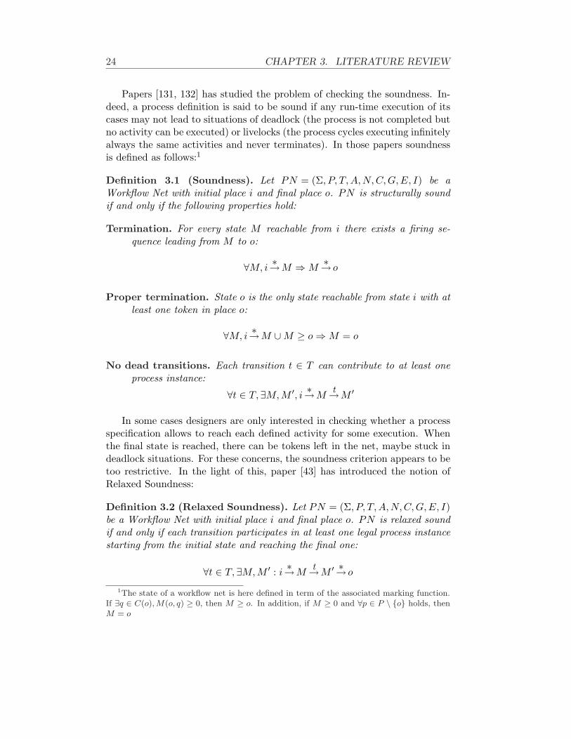
Papers [131, 132] has studied the problem of checking the soundness. In-deed, a process definition is said to be sound if any run-time execution of itscases may not lead to situations of deadlock (the process is not completed butno activity can be executed) or livelocks (the process cycles executing infinitelyalways the same activities and never terminates). In those papers soundnessis defined as follows:1
Definition 3.1 (Soundness). Let PN = (Σ, P, T, A,N,C, G, E, I) be aWorkflow Net with initial place i and final place o. PN is structurally soundif and only if the following properties hold:
Termination. For every state M reachable from i there exists a firing se-quence leading from M to o:
∀M, i∗→M ⇒ M
∗→ o
Proper termination. State o is the only state reachable from state i with atleast one token in place o:
∀M, i∗→M ∪M ≥ o ⇒ M = o
No dead transitions. Each transition t ∈ T can contribute to at least oneprocess instance:
∀t ∈ T,∃M,M ′, i ∗→Mt→M ′
In some cases designers are only interested in checking whether a processspecification allows to reach each defined activity for some execution. Whenthe final state is reached, there can be tokens left in the net, maybe stuck indeadlock situations. For these concerns, the soundness criterion appears to betoo restrictive. In the light of this, paper [43] has introduced the notion ofRelaxed Soundness:
Definition 3.2 (Relaxed Soundness). Let PN = (Σ, P, T, A, N, C,G, E, I)be a Workflow Net with initial place i and final place o. PN is relaxed soundif and only if each transition participates in at least one legal process instancestarting from the initial state and reaching the final one:
∀t ∈ T,∃M, M ′ : i∗→M
t→M ′ ∗→ o
1The state of a workflow net is here defined in term of the associated marking function.If ∃q ∈ C(o), M(o, q) ≥ 0, then M ≥ o. In addition, if M ≥ 0 and ∀p ∈ P \ {o} holds, thenM = o
3.1. PROCESS MODELLING LANGUAGES 25
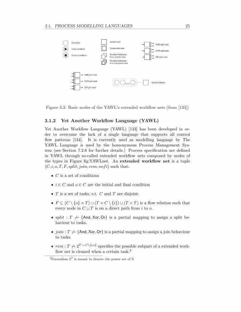
Figure 3.3: Basic nodes of the YAWL’s extended workflow nets (from [133])
3.1.2 Yet Another Workflow Language (YAWL)
Yet Another Workflow Language (YAWL) [133] has been developed in or-der to overcome the lack of a single language that supports all controlflow patterns [134]. It is currently used as modelling language by TheYAWL Language is used by the homonymous Process Management Sys-tem (see Section 7.2.6 for further details.) Process specification are definedin YAWL through so-called extended workflow nets composed by nodes ofthe types in Figure fig:YAWLnet. An extended workflow net is a tuple(C, i, o, T, F, split, join, rem, nofi) such that:
• C is a set of conditions
• i ∈ C and o ∈ C are the initial and final condition
• T is a set of tasks, s.t. C and T are disjoint.
• F ⊆ (C \ {o} × T ) ∪ (T ×C \ {i}) ∪ (T × T ) is a flow relation such thatevery node in C ∪ T is on a direct path from i to o.
• split : T 6→ {And, Xor,Or} is a partial mapping to assign a split be-haviour to tasks.
• join : T 6→ {And, Xor, Or} is a partial mapping to assign a join behaviourto tasks.
• rem : T 6→ 2T ∪ C\{i,o} specifies the possible subpart of a extended work-flow net is cleaned when a certain task.2
2Formalism 2S is meant to denote the power set of S

26 CHAPTER 3. LITERATURE REVIEW
• nofi : T 6→ N × N∞ × N∞ × {dynamic, static} is a partial functionthat specifies the number of instance of each task (minimum,maximum,threshold for continuation) and whether the instance creations is dy-namic or static.3
Extended workflow nets are a flavour of workflow net which is able to handle:
Multiple instances. YAWL is able to enable concurrently multiple instancesof specific tasks. The exact number may be determined at run-timeaccording to some variables/conditions evaluated on the process instancethat multi-task is part of.
Advanced Synchronization Pattern. YAWL handles some patterns in amore natural way than workflow nets (such as or split/join). Workflownets are able to specify most of them even if they need to use arteficesthat require complex and prolix definitions.
Non-local Firing Behaviour. Workflow nets can determine whether atransition can or cannot fire on the basis of the sole input places. YAWLcan enable activities considering tokens on other places as well as it al-lows transitions to delete tokens [146] through the definition of functionrem
It allows also to divide the extended workflow net in sub-nets, which are madeindependent of the main net they are integrated in; therefore, sub-nets can bereused in different specifications. The YAWL’s execution semantics of activ-ities are well-defined state transitions systems. Every atomic task is actuallythe sequence of four transitions: (i) task instance active; (ii) enabled but notyet running; (iii) currently executing; (iv) completed. Moreover it allows todefine so-called composite tasks, which are links to other extended workflownets. Composite tasks facilitate the modularisation of complex specificationsand make easier reading those existing.
3.1.3 Event-driven Process Chains (EPCs)
Event-driven Process Chain (EPC) is a rather informal notation developed aspart of an holistic modelling approach named the ARIS framework [82, p. 35].
There are several formalisations of the EPC syntax as the original paperintroduces EPC in an informal way. Here we specifically use the definitiongiven in [96]:4
A tuple EPC = (E,F, C, l, A) is an Event-driven Process Chain if:3Formalism N∞ identifies the set of natural numbers plus the infinite4The EPC syntax has been also extended with the data and resource perspective, i.e.
process participants and data objects manipulated by activities. But here we do not considerworthy describing such extensions.
3.1. PROCESS MODELLING LANGUAGES 27
• E, F, C are disjoint, finite, non-empty sets;
• l : C → {and, or, xor};• A ⊆ (E ∪ F ∪ C)× (E ∪ F ∪ C);
Elements of E, F, C are respectively named events, functions and connec-tors. Mapping l assigns to each connector a specific type, representing the or,and, xor semantics.
Moreover, some conditions have to hold:
• Graph (K, C) has to denote a connected graph;
• Every function has exactly one incoming and one outcoming edge;
• There exists at least one start and one end event. Start events are de-noted by having exactly one outgoing edge and no ingoing edge. Vicev-ersa, end events have no outgoing edge and one ingoing edge;
• Each event that is not start or end has got one incoming and one out-coming event;
• Each event can be followed only by functions and each function only byevents. Events can be followed by multiple functions (and functions bymultiple events) if there are intermediate connectors.
• Events cannot be followed by an or or xor split node.
3.1.4 π-calculus
One of the main problems of Workflow Nets is that they have no suitable meth-ods to compose several nets by concurrent operators. The concurrency canbe anyway obtained by clever artifices. Unfortunately such artifices make themodel more complex with consequences of the formal verification, which be-comes more difficult. By using such artifices, verification of a large model maybe computationally infeasible. The use of π-calculus overcomes the problem:it provides tools for building high-level system by composing its sub-systemsusing concurrency operators.
The π-calculus was introduced by Milner [100]. so as to represent concur-rent mobile systems and their interactions. The term mobility refers to theway in which process execution evolves. Milner began studying how computerprocesses are embodied in computer systems and networks. He observed thatcomputer processes merge together elements for computing and for communi-cating. As result, processes are made known only through the data exchanged.For instance, CPU computations are shown to external components for the in-formation stored into the registers.

28 CHAPTER 3. LITERATURE REVIEW
The syntax of π-calculus
π-calculus is a CCS flavour and, as CCS, is based on the concept of name:channels to make communicate different sub-systems are named as well asvariables and data are. The important improvement with respect to CCS isthat π-calculus does not distinguish among the names of the different elements.Therefore, it is possible to send through channels a name representing anotherchannel. The receiver can, then, parameterise the communication channel onthe basis of the name returned. In π-calculus everything is considered asa process that exchanges data with other processes exclusively by channels.Specifically, here we are referring to to polyadic π-calculus , an extended versionthat allows to send and receive tuple of values through channels. The logicconjunction points between processes and channels are named ports.
In this section, processes are always uppercase where names are lower-case. Moreover m = (m1,m2, . . . , mn) refers to any sequence of names. Thefollowing constructs are the basic of π-calculus:
The input prefix. Process a(~x).P receives the sequence ~x of names on theport a; then, it behaves as P .
The output prefix. Process a(~x).P sends the sequence ~x of names on theport a; then, it behaves as P .
The summation. Process P1 + P2 behaves in a way that either P1 or P2 isperformed. The choice is nondeterministic and works similarly to thenondeterministic choice between actions of ConGolog and IndiGolog.
The composition. Process P1 | P2 performs both process P1 and P2. More-over, both are performed in parallel and can communicate with eachother by channels. Abbreviation
∏mi=1(Pi) = P1|P2| . . . |Pm denotes the
composition of m processes.
The restriction. Process (νy)P behaves like P but where y is a so-calledrestricted name. That is to say y cannot be a channel for communicatingwith the external environment (for example other processes).
The matching. The [x = y].P process behaves like P if x and y are the samename. Otherwise, it behaves like the 0 process, that is the process doingnothing
The replication. The !P process behaves like the one obtained by re-executing process P an arbitrary deal of times.
Moreover, expression P [~a/~b] in the π-calculus refers to the process obtainedfrom P by substituting each name ai ∈ ~a for each name bi ∈ ~b.

3.1. PROCESS MODELLING LANGUAGES 29
Modeling workflow using π-calculus
A first significant effort in modelling process in π-calculus is given in [44]. Theapproaches to formally model processes by π-calculus share the idea everythingis a process: resources, activities, work lists and so on. The interaction betweenprocess participants and the engine is also modeled in this way. In our opinion,that fine granularity is not needed, but, rather, it causes the production ofspecifications which are less readable.
Workflows an alternative approach, which produces specifications that aremore slender (and, hence, more readable) than what generated by the afore-mentioned approach. In addition, this approach seems to be more solid andfeasible as the paper introduces a mapping in π-calculus for several differentcontrol-flow patterns. In [114], every activity is an independent π-calculus pro-cess and coming-before relationships are modelled by values read and writtenon channel ports. The complete process definition for a basic activity A is:
Adef= x.[~a = ~b].τA.y.0
That means a process receives a trigger through port x mapping to an event(e.g., the completion of a preceding activity). Then, the process makes acertain comparison [~a = ~b], performs some internal work τA and, later, notifiesthe completion writing on a certain channel port y. Of course, that is thecase of a single activity in a sequence. In general, an activity can be enabledonly after several complete (say m); in addition, the completion can enable osubsequent activities. Therefore, supposing also n conditions to be checked,the general formalisation for an activity A is the following:
Adef= {xi}m
i=1.{[~ai = ~bi]}ni=1.τA.{y}o
i=1.0
In this way, all of basic control flow patterns can be mapped. A more compre-hensive discussion and mappings is entrusted to paper [114]. Finally, the wholeprocess specification is built by composing all different nodes A1, . . . , An:
Pdef=
m∏
i=1
Ai
As far as checking for soundness, Puhlmann [113] provides means to char-acterize different soundness properties, such as relaxed and classical, usingbisimulation equivalence. UppSala Universitet has developed independentlythe MWB (Mobility Workbench [138]) for manipulating and analyzing any mo-bile concurrent systems described in π-calculus, including business processes.

30 CHAPTER 3. LITERATURE REVIEW
Language Formal StructuralSoundness
SemanticSoundness
Non-AtomicExecution
Planning State vsEventBased
WorkflowNet
Yes Yes No No EarlyStage
State
YAWL Yes Yes No Yes No StateEPC No Partially No No No Eventπ-calculus Yes No No Yes No EventGraph-basedlanguages
Semiformal
Yes Partially No No Event
Table 3.1: A comprehensive comparison
3.1.5 Discussion
Table 3.1 summarizes the assessment made in the light of the requirementsdescribed at the beginning of this section. A analysis of the results assessed isgiven below, where every language is discussed separately taking requirementsinto account. As pointed out by the table, no language addresses all thefeatures that the framework proposed in this thesis require, including thenecessity of being based on a notion of state.
Workflow Nets. It is a sound formalism for representing business processeswhich is formal enough to enable reasoning and process verification. Currentresearch directions in term of verification have been just limited to check thestructural soundness according to Definition 3.1. Such a checking does notconsider the actual environment where processes are enacted. As a conse-quence, when running, process instance may get stuck since some activitiesmight require certain environmental conditions that do not currently hold. Nowork is currently trying to address such a kind of execution monitoring.
In theory, Workflow nets is suitable as process modelling language for theadaptation framework in this thesis. Indeed, pre- and post-conditions can beformally specified as well as it is precisely and unambiguously defined when acertain state is final and how to pass from a state to another one.
But there are some drawbacks which limit its application:
1. When transitions fire, tokens are consumed from their input places andothers are put on the output places. These steps are atomic in the sensethat nothing can happen in the meanwhile (e.g., firing of other tran-sitions). Considering a transition firing represents an activity perfor-mance, such atomicity is somehow in contradiction. During the activityexecution, events can happen and change the environment, and thatmay cause started activities to be unable to complete. Our adaptationframework has to be able to monitor even during the activity perfor-

3.1. PROCESS MODELLING LANGUAGES 31
mances. Workflow nets cannot be directly used, unless some artificesare introduced, which would make explode the complexity of the model.
2. Algorithmically, it would allow designers to define processes, and prob-ably also to monitor and recovery as there exist researches on Petri-Netbased planners (e.g., [63]). Nevertheless, IndiGolog allows, in addition,one to encode the whole framework only by itself (see next chapter).Indeed, the aspect of monitoring and recovering is directly modelledthrough IndiGolog procedures in a very natural way. Workflow Net isa “low-level” formalism and, as such, it cannot achieve easily the sameresults. For instance, we could concretely code the whole frameworkthrough the sole IndiGolog interpreter (see Chapter 5) whereas usingWorkflow Nets would have required different parts to be developed us-ing different languages, and additional effort would have been needed,without gaining concrete benefits. It is also worthy saying that Petri-Netbased planning techniques are not as mature and efficient as those basedon logics. Indeed, as far as our knowledge, there exist no planners whichtake input any form of PN coding.
YAWL. An extended workflow net (C, i, o, T, F, split, join, rem, nofi) canbe reduced to an usual workflow net (C, T, F ), obviously loosing the additionalfeatures. It follows that most of the limitations of workflow nets also hold forYAWL. The YAWL formalism overtakes only the limitation concerning themodelling the temporal aspects of activity executions, since it models explictlythe different states in which an activity can be. On the other hand, there existno planners for YAWL.
EPC. Event-driven Process Chains allow process designers to model pro-cesses from a user-oriented perspective. The alternation of events and func-tions yields to process representations that may become very complex. Thatis the reason why they are generally used to model processes at a high level,where representations generally remain reasonably small. This high-level pro-cess specifications are meant to be read and evaluated by humans and cannotserve as input for Process Management Systems.
As also argued in [74], the informal EPC’s nature cannot be directly trans-lated into a proper semantics. Describing in details pre- and post-conditionsof functions (i.e., tasks/activities to perform) would result in huge specifica-tions. Moreover, there are no standards to formalise conditions in a way theycan be used for reasoning, such as our adaptation framework would require.As a matter of fact, most of the research work on EPCs is currently address-ing to the problem of verifying the structural soundness of specifications. Forinstance, Mendling et al. [97] make an analysis of 604 SAP reference models

32 CHAPTER 3. LITERATURE REVIEW
in order to look whether some of them contain structural errors. Specifically,their correctness criterion is based on relaxed soundness. Indeed, EPCs areargued as being frequently used to capture the expected behaviour withoutconsidering unwilling execution leading to deadlocks or livelocks. Mendling etal. [96] define a new enriched formal definition of EPCs which enables to checkfor the structure soundness.
Apart from the verification of formal correctness at design-time, a processrepresented in EPC has to be executed at run-time, achieving the outcomesit has been devised for. There exists no research work for verifying whethersuch processes achieve the expected results in the actual real-world scenario.We are confident to state that would be in any case hard since it is difficultto enter into the activity semantics since pre- and post-conditions of activitiesare not formally represented in a proper way.
π-calculus. it is a formal and sound formalism to represent business pro-cesses and reason on it. As for other formalisms, most of research workhas been focused on verifying the structural soundness of process specifica-tion. But, nothing is told on how to monitor in at run-time the progressionof running instances specified in π-calculus and check whether they can suc-cessfully terminate in the current state of the world. Moreover, π-calculusis event-based: transitions are modeled explicitly where the states betweensubsequently transitions are only modeled implicitly. That introduces manycritical issues. Firstly, it is difficult to monitor deviations since these concernthe gap between the state expected and that monitored. Secondly, plannersare generally based on state and, hence, it is needed to rebuild a certain def-inition of states from the message model of π-calculus. This step, which canbe made, requires additional effort without gaining a real benefit.
Graph-based languages. These drawbacks are also shared with most ofgraph-based languages. Graph-based languages, which are not described indetail in the following sub-sections, are a collective name for some languageswhich are used by or, simply, meant for commercial or prototypal ProcessManagement Systems in order to define process specifications. This classcomprises, for instance, BPMN [105] or those used by AgentWork [101] orAdeptFlex [117]. Process elements, such as activities, joins or splits, are rep-resented by nodes that are connected by proper edges. These languages aretypically event-based, that represents a serious issues as said before, and typ-ically allow designers to represent specifications in a more formal way thanEPC. However, these languages are anyway still too informal to check whetherdeviations happened in the environment that require a recovery plan.

3.2. RELATED WORKS ON ADAPTABILITY 33
ProcessAdaptation
Adaptation ofProcess
Specifications
Ad-hocAdaptation of
Single Instances
ManualAdaptation
ManualAdaptation
AutomaticAdaptation
Unplanned Pre-planned
Migration of runninginstances
Checking forstructural and semantic
soundness Our Approach
Figure 3.4: A taxonomy of the adaptation techniques
3.2 Related Works on Adaptability
This section discusses the levels of support for process adaptability/flexibil-ity and exception handling in several of the leading commercial products andsome academic prototypes. Figure 3.4 shows a taxonomy of the adaptationtechniques. Changes to a process can be classified in two main groups: evolu-tionary and exceptional changes.
Orthogonally, there is the issue of verifying the soundness of the up-dated process specifications and/or of running instances adapted to occurredchanges. Whereas there are a lot of research on the structural soundness,as widely discussed in Section 3.1, little work has been done on the seman-tic soundness of process changes [125, 87]. The most valuable approach isimplemented in ADEPT (see later in this section), but activity conflicts aredefined manually and not inferred automatically over the activity pre- andpost-conditions.
Evolutionary changes concern a planned migration of a process to an up-dated specification which, for instance, implements new legislations, policiesor practices in business organisations, hospitals, emergency management, etc.Typically the inclusions of new evolutionary aspects are made manually bythe process designer. When dealing with process specification changes, there

34 CHAPTER 3. LITERATURE REVIEW
try{
activity1;activity2;activity3; || subProcess();
}catch(Disconnection) { ... }catch(Devices Down) { ... }catch(Exception1) { ... }catch(Exception2) { ... }catch(Exception3) { ... }catch(Exception4) { ... }
try{
activity1;activity2;activity3; || subProcess();
}catch(AnyException){ /* Generic method */ }
Pre-planned Unplanned
Table 3.2: A Java-like model for describing Automatic Adaptation
is the issue of managing running instances, and, possibly, making migrate suchinstances to the updated specification. Simple solutions, such as aborting run-ning instances or continuing with the old specification, may not be workingfor obvious reasons. Aborting, when possible, would cause some work alreadydone to be lost, and using old specification may result in applying old legisla-tion and, hence, would be inappropriate and impracticable. Casati et al. [19]define a complete, minimal, consistent and sound set of modification primi-tives to modify specifications. This paper describes also the constraints underwhich running instances can be migrated to new updated specifications. Un-fortunately, it does cover the issue of applying automatically the changes, and,hence, a domain expert is supposed to manually apply them. Weske [142] goesbeyond and provides a technique that is able to adapt running cases by adding,deleting and moving activities in order to adhere to a new specification. Thistechnique has been, then, implemented for WASA [139]. Similarly to Casatiet al. [19], Weber et al. [140] suggest a set of change patterns (such as insert-ing, deleting or moving process fragments) that may be useful when modifyingspecifications. The set proposed is wider than what is in [19]; in addition, thepaper reports how many of change patterns are actually implemented in themost spread Process Management Systems.
On the other side, there are the exceptional changes which are charac-terised by events, foreseeable or unforeseeable, during the process instanceexecutions which may require instances to be adapted in order to be carriedout. Since such events are exceptional, process specifications do not need anymodifications. There are two ways to handling exceptional events. The adap-

3.2. RELATED WORKS ON ADAPTABILITY 35
tation can be manual : once events are detected, a responsible person, experton the process domain, modifies manually the affected instance(s). The adap-tation can be automatic: when exceptional events are sensed, PMS is able tochange accordingly the schema of affected instance(s) in a way they can stillbe completed.
Automatic adaptation techniques can be broken down in two furthergroups: pre-planned or unplanned. Using pre-planned adaptation techniques, aresponsible person should foresee at design-time all possible exceptional eventsand, for each of them, should define a proper handling strategy. This kind ofpre-planned approach is named Flexibility by design in [123]. The same paperintroduces also Flexibility by underspecification: in certain cases, the designermay be aware of that certain exceptional events may occur, but the recoverystrategies cannot be known in advance but only defined at run-time. Sev-eral proposals have been made to define pre-planned policies, such as ControlICN [16] or Event-Condition-Action Rules [20]. Unplanned adaptation tech-niques, conversely, do not require to anticipate all of the possible expectedevents but there exists only one strategy, which is able to recover from anydeviation.
Table 3.2 is meant to clarify the differences between the two techniquegroups by using the Java metaphor. The left-hand side represents pre-plannedadaptation where the process is put in a try block and there exists severalcatches, one for each expected exceptional event. Each catch block imple-ments the strategy for recovering from the corresponding event. The right-hand side aims at describing Unplanned adaptation, where, by contrast, onlyone catch exists, which describes the generic strategy to recovery from anypossible.
The remaining of this section is devoted to enumerate how some commer-cial products and academic prototypes address process adaptation. Table 3.2summarises the comparison of existing approaches as far as concern ad-hocadaptation of single instances. The last row shows how SmartPM is envi-sioned in this categorisation. Rows having no checkmark refer to the PMSsthat do not allow to change directly running instances during the execution.In those systems, ad-hoc adaptation is done undirectly: such PMSs allowto modify specifications and corresponding changes are, then, propagated torunning instances.

36 CHAPTER 3. LITERATURE REVIEW
Product Manual Pre-planned UnplannedYAWL XCOSA X XTibco X XWebSphere X XSAP The right policy chosen at run-timeOPERA X XADEPT2 XADOME XAgentWork XCBRFlowWASASmartPM X
Table 3.3: Features provided by the most spread PMSs for ad-hoc adaptationof single instances
Discussion. SmartPM can be classified as belonging to the group of adap-tation strategies that are automatic and unplanned. We are not interestedin the problem of migrating process instances to updated models. Indeed,such a problem is generally related to long-term processes; pervasive pro-cesses, such as those of emergency management or pervasive health-care, areshort-term as they complete relatively quickly. For instance, the process ofsaving people under debris or of provide medical assistance to injured peoplehas to be carried out very quick to limit the risks for persons.We cannot manage adaptation by pre-planned techniques or manually forsome reasons. Firstly, in pervasive scenarios, the environment is continuallychanging and, therefore, events that require processes to be adapted are notexceptional but very frequent. Therefore, it is not feasible to think abouta responsible person who is devoted to adapt manually process instanceson very frequent time basis. Moreover, this would delay the completionof process instances, and that should be avoided as much as possible sincetypically pervasive processes are time-constrained.Pre-planned techniques should be avoided, as well. Indeed, pervasive pro-cess management systems, such as SmartPM, are expected to be used inenvironments where there occur a great deal of possible exceptional events.Foreseeing all of them is not feasible; even if we handled many exceptionalevents, we would forget to consider others that may occur.The section has broadly discussed existing approaches on the concern ofadapting processes, and Table 3.2 summarises the discussion. It is easy tosee almost all approaches are addressing the problem by manually adaptingthe process instances or through various flavours of pre-planned techniques.The lack of unplanned techniques can be partially motivated by the factthat the majority of PMSs are intrinsically intended for traditional businessprocesses where either every change or every recovery policy is generallysubject to the chief approval.

3.2. RELATED WORKS ON ADAPTABILITY 37
YAWL provides one the most interesting approaches for adaptability [1](more details about YAWL are given in Section 7.2.6). In YAWL each activitymay be associate to an extensible repertoire of actions, one of which is chosenat run-time to carry out the activity. These actions are named “worklet”: aworklet is a small, self-contained, complete process which handles one specifictask (action) in a large and composite process. On the basis of hierarchicalRipple-Down rules defined contextually, an activity is dynamically replaced bythe most appropriate of the available worklets. This approach is pre-planned :the substitution rules are defined at design-time, possibly manually updatedat run-time, and never inferred on the process instance state.
WASA systems is totally manual [139] and concerns modifying process spec-ification according to evolutionary changes. As discussed above in this section,It focuses also on checking whether running instances can be migrated to up-date specifications [142].
COSA allows to associate sub-processes to external “triggers” andevents [27]. But the adaptation policies are pre-planned : associations trig-gers to sub-processes have to be defined at design-time. COSA allows alsomanual instance adaptations at run-time by using change patterns such asreordering, skipping, repeating, postponing or terminating steps.
Tibco iProcess Suite provides constructs called “event nodes” [127]. Theyallow designers to define handlers for expected events to be activated whenthey occur. Policies comprise the possibility of suspending processes eitherindefinitely or wait until a deadline occurs. All of exceptions for which nohandler exists are forward to the “default exception queue” to be handledmanually.
WebSphere MQ Workflow supports deadlines and, when they occur,branches to pre-planned exception paths and/or sends notification messagesto specific administrator [68]. Administrators can manually suspend, restartor terminate processes, as well as they can reallocate tasks.
SAP Workflow allows to define exception handling processes [73]. Al-though they are defined at design-time, they cannot be associated to excep-tional events at that time. At run-time, when an event occurs, these handlingprocesses are proposed to the administrator, who can manually select the mostappropriate one. There is no way to define properties in order to filter outsome handlers on the basis of the case and the occurred event.
38 CHAPTER 3. LITERATURE REVIEW
OPERA prototype allows to associate at design-time an handler for acertain event to single tasks [59]. That means such an handler is launched,only when the event occurs and blocks those tasks. It allows also to definemore general handlers for certain events to associate to all tasks. When anexceptional event occurs, the process is stuck and, if any, the correspondinghandler for that event and that task is invoked. If it cannot recover theexecution or there is no specific handler for that task and event, the generalhandler for that event is used. If it does not exist or cannot solve, manualadaptation can be used.
ADEPT is able to handle both exceptional events and evolutionarychanges [20]. All of changes can be achieved by manual interventions, al-though ADEPT provides a minimal support to facilitate such operations.As far as evolutionary changes, it supports also the feature of migratingrunning instances to the updated specifications. Version 2 introduces newfeatures [118, 54], such as the structural and semantic correctness of thechanges [87], but the ADEPT approach should be still considered as totallymanual. ADEPT is one of the few works dealing with the issues of checking forsemantic correctness, and this aspect is very valuable for Process ManagementSystems like SmartPM where adaptation is willing to be completely automatic.Unfortunately, the semantic correctness relies on a significant effort for config-uration. Indeed, checking is not computed automatically on the basis of pre-and post-conditions of activities but it relies on the semantic constraints thatare defined manually by designers at design-time. This is also related to thesemi-formality of the process modelling language of ADEPT, which does notallow automatic reasoning. ADEPT2 relies on two relations between pairs ofactivities, namely dependency and exclusion. These relations allow to specifyrespectively (i) what activities are depending (the first in pairs can be exe-cuted only if the second has been also executed) and (ii) what activities arenot compatible in achieving the outcomes of process instance.
ADOME system provides some support for manual changes as well as forpre-planned policies [26]. An exception handler is linked to a certain task,instead of being associated to events. When a given exceptional event is suchthat it makes impossible to execute a certain task, the recovery policy for thattask is used, if any.
AgentWork provides the ability to modify process instances by droppingand adding individual tasks based on Event-Condition Rules rules [101]. Theyare formally defined by ACTIVETFL, which combines Frame Logic, a logicbased on the notion of objects, with some features available for temporal logics.
3.3. CASE HANDLING 39
Consequently, AgentWork is comprised in the pre-planned approaches. Sincethe graph-based model used by AgentWork is not very formal, there is noway to check for semantic soundness and conflicts. Therefore, some rules maygenerate incompatible recovery actions.
CBRFlow uses a case-based reasoning approach to support adaptation ofworkflow specifications to changing circumstances [141]. Case-based reasoning(CBR) is the process of solving new problems based on the solutions of similarpast problems: users are supported to adapt process specifications by takinginto account how other specifications have been modified in the past to followthe evolutionary changes.
3.3 Case Handling
Case Handling aims at providing less rigidity than usual Process ManagementSystems by leveraging process orientation and data orientation to route theexecution of processes [129, 130]. Flower [12] is one of the few systems thatuse the Case Handling paradigm
Case Handling meets the requirements in some application scenarios whereprocess participants are highly skilled. In such cases, organizations want par-ticipants to be more autonomous in driving and control the case executions.Being more rigid, traditional Process Management technologies does not allowexpert participants to make deviate processes from the prescribed schema. Insome scenarios, from the one side business process management is still valu-able, but from the other side participants should be able to perform a broadrange of activities and, consequently, drive how processes are carried on.
Let us consider the scenarios of a process for the delivery of certain goods.At an certain stage, participants may be required to fill in a certain form toprovide some data that also include some information for the mail delivery(e.g., the mail address, the post code). The next step consists in sendingthe goods and could be done as soon as delivery information is available. Bytraditional Process Management Technology, goods can be sent only when thewhole form is filled in, including information which is not directly needed forthe delivery. Case Handling approaches allow to enable the next step as soonas the delivery information is put into the form and committed, although theform itself is not yet wholly completed. Indeed, the work-item enablementis mainly drive by data availability in the case handling approach, whereasprocess management steers enablement by the control flow (coming-beforerelationship).
In case handling, every activity is associated with at least a data objectdefinition. There exist two main types of association: mandatory and re-

40 CHAPTER 3. LITERATURE REVIEW
stricted. If a data object is mandatory for a certain activity, then it has tobe entered in order to complete that activity. A data object is restricted to acertain activity set if it can be entered only by activities in that set. Associ-ations mandatory and restricted are orthogonal; for instance, if a data objectmandatory and restricted to a given activity, it means it is going to be enteredby that activity (and by none else). Data objects may also be free in the sensethat it can be entered in any moment. More information about case handlingcan be read in the aforementioned papers.
From the one side, highly dynamic and pervasive scenarios could benefitfrom less rigidity, which is somehow intrinsical in these settings. Furthermore,weak activity boundaries and data-driven nature of Case Handling prevent inseveral cases the need for changes. Finally, the environment of the execution ofprocesses running in dynamic scenarios are often continuously changing and,hence, it is really valuable for a participant to be going over the old processschema and decide to handle multiple activities in one go.
But, from the other side, Case Handling systems experience some short-comings:
1. Case Handling is data-driven: a certain state is reached when some databecome available. Consequently, handling such cases has to be mainlyperformed within the system itself: the activity outcomes are alwaysrepresented by the data produced. In many pervasive scenarios, suchas healthcare or emergency management processes, the main effects ofactivities are not represented in the systems themselves. For instance,the outcomes of saving or aiding victims are not naturally definable asdata updated or manipulated.
2. The nature of case handling makes quite difficult to modify cases whichare already running as also argued in [129, 130, 56]. Generally, adapt-ability in case handling is designated to affect new cases going to becreated after the modification. In highly dynamic and pervasive sce-narios, changes should affect only running cases as they are fired byexogenous events which somehow invalidated them.
3. Activities are no longer pushed to participants by the system. The sys-tem becomes a discreet support to accomplish activities rather than away to control the case progressions in a mechanic way. This might beproblematic in some high dynamic and pervasive scenarios where pro-cess participants have to be continuously pushed by PMS to perform thework assigned as fast as possible.
Therefore, the Case Handling approach is not actually feasible for the sce-narios at which we are aiming. Gunther et al. [56] start discussing a possible

3.3. CASE HANDLING 41
integration of case handling and typical Process Management. They startexploring how ideas from case handling can be introduced into Process Man-agement Systems to gain the corresponding benefits and what changes wouldbe required. Unfortunately, the discussion is still at an initial stage and,hence, unable to address the concerns of process management for pervasivescenarios.

42 CHAPTER 3. LITERATURE REVIEW

Chapter 4
A General Framework forAutomatic Adaptation
This chapter is devoted to describe a general conceptual framework forSmartPM, the adaptive Process Management System (PMS) object of thisthesis. This chapter aims at presenting a practical technique for solving adap-tation, which is based on planning in AI. Moreover, we prove the correctnessand completeness of the approach.
In SmartPM, process specifications associates every task to a set of capa-bilities that the service going to execute it has to provide. Every task canbe assigned to a given service that provides all capabilities required if a setof conditions hold. Conditions are defined on control and data flow (e.g., aprevious task has to be finished, a variable needs to be assigned a specificrange of values, etc.). This kind of conditions can be somehow considered as“internal”: they are handled internally by the PMS and, thus, easily control-lable. Another type of conditions exists, the “external” ones: they depend onthe environment where process instances are carried on. These conditions aremore difficult to keep under control and a continuous monitoring to detectdiscrepancies is required. Indeed we can distinguish between a physical realityand a virtual reality [31]; the physical reality is the actual values of conditions,whereas the virtual reality is the model of reality that PMS uses in makingdeliberations. A PMS builds the virtual reality by assuming the effects oftasks/actions fill expectations (i.e., they modify correctly conditions) and noexogenous events break out, which are capable to modify conditions.
When the PMS realizes that one or more events caused the two kinds ofreality to deviate, there are three possibilities to deal with such a discrepancy:
1. Ignoring deviations – this is, of course, not feasible in general, since thenew situation might be such that the PMS is no more able to carry outthe process instance.
43
44 CHAPTER 4. FRAMEWORK FOR AUTOMATIC ADAPTATION
2. Anticipating all possible discrepancies – the idea is to include in the pro-cess schema the actions to cope with each of such failures. As discussedin Chapter 3, most of PMSs use this approach. For simple and mainlystatic processes, this is feasible and valuable; but, especially in mobileand highly dynamic scenarios, it is quite impossible to take into accountall exception cases.
3. Devising a general recovery method able to handle any kind of exoge-nous events. As discussed in Chapter 3, the process is defined as ifexogenous actions causing deviations cannot occur, that is everythingruns fine (the try block). Whenever the execution monitor (i.e., themodule intended for execution monitoring) detects discrepancies leadingthe process instance not to be terminable, the control flow moves to the(unique) catch block. The catch block activates the general recoverymethod to modify the old process P in a process P ′ so that P ′ can ter-minate in the new environment and its goals are included in those of P .Here the challenge is to automatically synthesize P ′ during the executionitself, without specifying a-priori all the possible catches.
In summary, this chapter aims (i) at introducing a general conceptualframework in accordance with the third approach previously described, and(ii) at presenting a practical technique, in the context of this framework, thatis able to automatically cope with anomalies. We prove the correctness andcompleteness of such a technique, which is based on planning techniques inAI. This chapter extends the framework published in paper [40] and revises itin the light of the subsequent operationalisation which was devised after thepaper.
Section 4.1 introduces some preliminary notions, namely Situation Calcu-lus and IndiGolog, that are used as proper formalisms to reason about processesand exogenous events. This section is not meant to give an all-comprehensiveand very formal introduction of the notions. It aims mostly at giving an overallinsight to those who are not very expert on such topics.
Section 4.2 presents the general conceptual framework to address adaptiv-ity in highly dynamic scenarios, and introduces a running example. Section4.3 presents the proposed formalization of processes, and Section 4.4 dealswith the adaptiveness. Section 4.5 presents the specific technique and provesits correctness and completeness. The chapter introduces and carries on alsoa concrete example, which is continually extended to cover and explain betterthe different concepts introduced. This example will be, then, operationalisedin the Chapter 5.

4.1. PRELIMINARIES 45
4.1 Preliminaries
SmartPM uses the situation calculus (SitCalc) to formalize adaptation. TheSitCalc is a logic formalism designed for representing and reasoning aboutdynamic domains [119].
We will not go over the situation calculus in detail; we merely note thefollowing components: there is a special constant S0 used to denote the initialsituation, namely that situation in which no actions have yet occurred; thereis a distinguished binary function symbol do, where do(a, s) denotes the suc-cessor situation to s resulting from performing the action a; relations (resp.functions) whose values vary from situation to situation, are called fluents,and are denoted by predicate (resp. function) symbols taking a situation termas their last argument. There is a special predicate Poss(a, s) used to statethat action a is executable in situation s.
We abbreviate with do([a1, . . . , an−1, an], s) the termdo(an, do(an−1, ..., do(a1, s))), which denotes the situation obtained froms by performing the sequence of actions a1, . . . , an.
Within this language, we can formulate domain theories which describehow the world changes as the result of the available actions. Here, we useaction theories of the following form:
• Axioms describing the initial situation, S0.
• Action precondition axioms, one for each primitive action a, character-izing Poss(a, s).
• Successor state axioms, one for each relational fluent F . The successorstate axiom for a particular fluent F captures the effects and non-effectof actions on F and has the following form:
F (~x, do(a, s)) ⇔ ΦF (~x, a, s) (4.1)
where ΦF (~x, a, s) is a formula fully capturing the truth-value of fluent Fon objects ~x when action a is performed in situation s (~x, a, and s areall the free variables in ΦF ).
• Unique names axioms for the primitive actions.
• A set of foundational, domain independent axioms for situations Σ as in[119].
A certain formula is uniform in situation s if s is the only situation termthat appears in it. Sometimes, we use situation-suppressed formulas; theseare uniform formulas with situation arguments suppressed (e.g. G denotes

46 CHAPTER 4. FRAMEWORK FOR AUTOMATIC ADAPTATION
Construct Meaninga primitive actionφ? wait for a conditionδ1; δ2 sequenceδ1 | δ2 nondeterministic branchπ x. δ nondeterministic choice of argumentδ∗ nondeterministic iterationif φ then δ1 else δ2 conditionalwhile φ do δ while loopδ1 ‖ δ2 concurrency with equal priorityδ|| concurrent iteration〈φ → δ〉 interruptproc P (~x) δ endProc procedure definitionP (~θ) procedure callΣ(δ) search operator
Table 4.1: IndiGolog constructs
the situation-suppressed expression for G(s)). Finally, we can introduce anordering among situations:
s ≤ s′ ⇔ ∃[a1, . . . , an−1, an].do([a1, . . . , an−1, an], s) = s′
On top of these theories of action, one can define complex control be-haviors by means of high-level programs expressed in Golog-like programminglanguages. Specifically we focus on IndiGolog [121], which provides a set ofprogramming constructs sufficient for defining every well-structured processas defined in [72]
IndiGolog is a logic-based languages born to program the behaviour of in-telligent agents and robots. It derives from ConGolog to which it adds basicallythe lookahead search operator. Such operator allows to simulate the executionof a process with the aim of searching for a successful termination before actu-ally performing the program in the real world. In its, turn ConGolog extendsthe original Golog by introducing construct for current execution of differentoperations. Table 4.1 summarizes the constructs of IndiGolog used in thisthesis.
In the first line, a stands for a situation calculus action term whereas,in the second line, φ stands for a formula over situation calculus predicatesincluding fluents, which are, then, evaluated in the current situation whenIndiGolog program execution reaches φ
The constructs listed included some nondeterministic ones. These include(δ1 | δ2), which nondeterministically chooses between programs δ1 and δ2,π x. δ, which nondeterministically picks a binding for the variable x and per-

4.1. PRELIMINARIES 47
forms the program δ for this binding of x, and δ∗, which performs δ zero ormore times. π x1, . . . , xn. δ is an abbreviation for π x1. . . . .π xn δ.
The constructs if φ then δ1 else δ2 and while φ do δ are the synchronizedversions of the usual if-then-else and while-loop. They are synchronized inthe sense that testing the condition φ does not involve a transition per se:the evaluation of the condition and the first action of the branch chosen areexecuted as an atomic unit. So these constructs behave in a similar way tothe test-and-set atomic instructions used to build semaphores in concurrentprogramming.
We also have constructs for concurrent programming. In particular(δ1 ‖ δ2) expresses the concurrent execution (interpreted as interleaving) ofthe programs δ1 and δ2. Observe that a program may become blocked whenit reaches a primitive action whose preconditions are false or a wait action φ?whose condition φ is false. Then, execution of (δ1 ‖ δ2) may continue providedanother program executes next. Another concurrent programming construct is(δ1 〉〉 δ2), where δ1 has higher priority than δ2, and δ2 may only execute whenδ1 is done or blocked. Finally, an interrupt 〈φ → δ〉 has a trigger condition φ,and a body δ. If the interrupt gets control from higher priority processes andthe condition φ is true, the interrupt triggers and the body is executed. Oncethe body completes execution, the interrupt may trigger again. 〈~x : φ → δ〉is an abbreviation for 〈∃~x.φ → π~x.δ〉.
Finally, the search operator Σ(δ) is used to specify that lookahead shouldbe performed over the (nondeterministic) program δ to ensure that nondeter-ministic choices are resolved in a way that guarantees its successful completion.
Formally two predicates are introduced to specify program transitions:
• Trans(δ′, s′, δ′′, s′′), given a program δ′ and a situation s′, returns (i) anew situation s′′ resulting from executing a single step of δ′, and (ii) δ′′
which is the remaining program to be executed.
• Final(δ′, s′) returns true when the program δ′ can be considered suc-cessfully completed in situation s′.
The predicate Trans for programs without procedures is characterized bythe following set of axioms:
1. Empty program:Trans(nil, s, δ′, s′) ⇔ false.
2. Primitive actions:
Trans(a, s, δ′, s′) ⇔ Poss(a[s], s) ∧ δ′ = nil ∧ s′ = do(a[s], s).

48 CHAPTER 4. FRAMEWORK FOR AUTOMATIC ADAPTATION
3. Test/wait actions:
Trans(φ?, s, δ′, s′) ⇔ φ[s] ∧ δ′ = nil ∧ s′ = s.
4. Sequence:
Trans(δ1; δ2, s, δ′, s′) ⇔
∃γ.δ′ = (γ; δ2) ∧ Trans(δ1, s, γ, s′) ∨ Final(δ1, s) ∧ Trans(δ2, s, δ′, s′).
5. Nondeterministic branch:
Trans(δ1 | δ2, s, δ′, s′) ⇔ Trans(δ1, s, δ
′, s′) ∨ Trans(δ2, s, δ′, s′).
6. Nondeterministic choice of argument:
Trans(πv.δ, s, δ′, s′) ⇔ ∃x.Trans(δvx, s, δ′, s′).
7. Nondeterministic iteration:
Trans(δ∗, s, δ′, s′) ⇔ ∃γ.(δ′ = γ; δ∗) ∧ Trans(δ, s, γ, s′).
8. Synchronized conditional:
Trans(if φ then δ1 else δ2 endIf, s, δ′, s′) ⇔φ[s] ∧ Trans(δ1, s, δ
′, s′) ∨ ¬φ[s] ∧ Trans(δ2, s, δ′, s′).
9. Synchronized loop:
Trans(while φ do δ endWhile, s, δ′, s′) ⇔∃γ.(δ′ = γ;while φ do δ) ∧ φ[s] ∧ Trans(δ, s, γ, s′).
10. Concurrent execution:
Trans(δ1 ‖ δ2, s, δ′, s′) ⇔
∃γ.δ′ = (γ ‖ δ2) ∧ Trans(δ1, s, γ, s′) ∨ ∃γ.δ′ = (δ1 ‖ γ) ∧ Trans(δ2, s, γ, s′).
11. Prioritized concurrency:
Trans(δ1 〉〉 δ2, s, δ′, s′) ⇔
∃γ.δ′ = (γ 〉〉 δ2) ∧ Trans(δ1, s, γ, s′) ∨∃γ.δ′ = (δ1 〉〉 γ) ∧ Trans(δ2, s, γ, s′) ∧ ¬∃ζ, s′′.Trans(δ1, s, ζ, s′′).
4.2. EXECUTION MONITORING 49
12. Concurrent iteration:
Trans(δ||, s, δ′, s′) ⇔ ∃γ.δ′ = (γ ‖ δ||) ∧ Trans(δ, s, γ, s′).
By using Trans and Final we can define a predicate Do(δ, s, s′) which,given the starting situation s and a program δ, holds for all possible situationss′ that result from executing δ starting from s such that situations s′ are finalwith respect to program δ′ remaining to execute. Formally:
Do(δ, s, s′) ⇔ ∃δ′.T rans∗(δ, s, δ′, s′) ∧ Final(δ′, s′)
where Trans∗ is the definition of the reflective and transitive closure of Trans.Notice that there may be more than one resulting situation s′ since IndiGologprograms can be non-deterministic (e.g., due to concurrency).
To cope with the impossibility of backtracking actions executed in the realworld, IndiGolog incorporates a new programming construct, namely the searchoperator. Let δ be any IndiGolog program, which provides different alternativeexecutable actions. When the interpreter encounters program Σ(δ), beforechoosing among alternative executable actions of δ, it performs reasoning inorder to decide for a step which still allows the rest of δ to terminate success-fully. More precisely, according to [30], the semantics of the search operatoris that
Trans(Σ(δ), s,Σ(δ′), s′) ⇔ Trans(δ, s, δ′, s′) ∧ ∃s∗.Do(δ′, s′, s∗).
If δ is the entire program under consideration, Σ(δ) emulates complete offlineexecution.
Finally, our adaptation procedure will make use of regression (see [4]and [119]). Let ϕ(do([a1, . . . , an], s)) be a SitCalc formula with situationargument do([a1, . . . , an], s). Then, Rs(ϕ(do([a1, . . . , an], s))) is the formulawith situation s which denotes the facts/properties that must hold beforeexecuting a1, . . . , an in situation s for ϕ(do([a1, . . . , an], s)) to hold (aka theweakest preconditions for obtaining ϕ). To compute the regressed formulaRs(ϕ(do([a1, . . . , an], s))) from ϕ(do([a1, . . . , an], s)), one iteratively replacesevery occurrence of a fluent with the right-hand side of its successor state ax-iom (Formula 4.1) until every atomic formula has a situation argument thatis simply s.
4.2 Execution Monitoring
The general framework is based on execution monitoring formally representedin SitCalc [83, 31]. After each action, the PMS has to align the internal world

50 CHAPTER 4. FRAMEWORK FOR AUTOMATIC ADAPTATION
Figure 4.1: Execution Monitoring
representation (i.e., the virtual reality) with the external one (i.e., the physicalreality), since they could differ due to unforeseen events.
When using IndiGolog for process management, tasks are considered aspredefined sequences of actions (see later) and processes as IndiGolog programs.
Before a process starts to be executed, the PMS takes the initial contextfrom the real environment as initial situation, together with the program (i.e.the process) δ0 to be carried on. The initial situation s0 is given by first-orderlogic predicates. For each execution step, the PMS, which has a completeknowledge of the internal world (i.e., its virtual reality), assigns a task to aservice. The only assignable tasks are those ones whose preconditions arefulfilled. A service can collect from the PMS the data which are required inorder to execute the task. When a service finishes executing the task, it alertsthe PMS of its completion.
The execution of the PMS can be interrupted by the monitor when amisalignment between the virtual and the physical reality is sensed. Whenthis happens, the monitor adapts the program to deal with such a discrepancy.
Figure 4.1 illustrates such an execution monitoring. The kind of moni-tor described here is a specialised version of what proposed by Soutchanskiet al. [31]. At each step, PMS advances the process δ in the situation s byexecuting an action, resulting in a new situation s′ with the process δ′ remain-

4.2. EXECUTION MONITORING 51
ing to be executed. The state1 is represented as first-order formulas that aredefined on situations. The current state corresponds to the boolean values ofthese formulas evaluated on the current situation.
Both the situation s′ and the process δ′ are given as input to the monitor.The monitor collects data from the environment through sensors (here sensoris any software or hardware component enabling to retrieve contextual infor-mation). If a deviation is sensed between the virtual reality as represented bys′ and the physical reality as s′′, the PMS internally generates a discrepancy~e = (e1, e2, . . . , en), which is a sequence of actions called exogenous events suchthat s′′ = do(~e, s′).2
Notice that the process δ′ may fail to be correctly executed (i.e., by as-signing all tasks as required) in s′′. If so, the monitor adapts the processby generating a new process δ′′ that pursues at least each δ′’s goal and isexecutable in s′′. At this point, the PMS is resumed and the execution iscontinued from δ′′ and s′′.
We end this section by introducing our running example, stemming fromproject WORKPAD, described in Chapter 2.
Example 4.1. The example is meant to code a possible process for managingthe aftermath of an earthquake: a team is sent to the affected area to make anassessment, which comprises taking some valuable photos, compiling a ques-tionnaire and sending all these data to the headquarter. Here we assume thatit is already known which buildings have to be assessed, namely buildings A, Band C. The team is equipped with PDAs in which some software services areinstalled and members are communicating with each other through a manetnetwork.
For each building, an actor compiles a questionnaire by using a certainsoftware service, that is an specific application installed on some actor devices.Compiling questionnaires can be done anywhere: that is, no movement is re-quired. Then, another actor/service has to be sent to the specific building tocollect some pictures (this, conversely, requires movement). Finally, accordingto the information filled in the questionnaire, a third actor/service evaluateseffectiveness of collected pictures. In order to evaluate properly the pictures, acertain minim number of pictures is required as input: if less, the evaluationcannot be done. Once evaluated, if pictures are judged as not effective, thetask of taking new pictures is scheduled again (as well as the evaluation of thenew pictures). When these steps have been performed for the three buildingsA, B and C, the collected data (questionnaires and pictures) are sent to theheadquarter.
1Here we refer as state both the tasks’ state (e.g, performable, running, terminated, etc.)and the process’ variables on which task firing and process routing is defined
2Note that the action sequence ~e might not be the one that really occurred.

52 CHAPTER 4. FRAMEWORK FOR AUTOMATIC ADAPTATION
Compile Questionnaire of building A
Move to destination A
Move to destination C
Move todestination B
Take photos ofdestination A
Evaluate photos
Compile Questionnaireof building B
Compile Questionnaireof building C
Evaluate photos Evaluate photos
Take photos ofDestination B
Take photos ofDestination C
¬evaluationOK(A) ¬evaluationOK (B) ¬evaluationOK (C)
evaluationOK (A)
evaluationOK (B)evaluationOK (C)
Send data to headquarter
Figure 4.2: A possible process to be carried on in disaster management sce-narios
Coordination and data exchange requires manet nodes to be continuallyconnected each other. But this is not guaranteed in a manet. The envi-ronment is highly dynamic, since nodes move in the affected area to carryout assigned tasks. Movements may cause possible disconnections and, so,unavailability of nodes, and, consequently, unavailability of provided services.Therefore processes should be adapted, not simply by assigning tasks in progressto other services, but also considering possible recovery of the services.

4.3. PROCESS FORMALISATION IN SITUATION CALCULUS 53
4.3 Process Formalisation in Situation Calculus
Next we detail the general framework proposed above by using Situation Cal-culus and IndiGolog. We use some domain-independent predicates to denotethe various objects of interest in the framework:
• service(a): a is a service
• task(x): x is a task
• capability(b): b is a capability
• provide(a, b): the service a provides the capability b
• require(x, b): the task x requires the capability b
Every task execution is the sequence of four PMS actions: (i) the assign-ment of the task to a service, resulting in the service being not free anymore;(ii) the notification to the service to start executing the task. Then, the ser-vice carries out the tasks and, after receiving the service notification of thetask conclusion, (iii) the PMS acknowledges the successful task termination.Finally, (iv) the PMS releases the service, which becomes free again. Weformalise these four actions as follows:
• Assign(a, x): task x is assigned to a service a
• Start(a, x, p): service a is allowed to start the execution of task x. Theinput provided is p.
• AckTaskCompletion(a, x): service a concluded successfully the execut-ing of x.
• Release(a, x): the service a is released with respect to task x.
In addition, services can execute two actions:
• readyToStart(a, x): service a declares to be ready to start performingtask x
• finishedTask(a, x, q): services declares to have completed the executionof task x returning output q.
The terms p and q denote arbitrary sets of input/output, which depend onthe specific task. Special constant ∅ denotes empty input or output.
The interleaving of actions performed by the PMS and services is as follows.After the assignment of a certain task x by Assign(a, x), when the service a isready to start executing, it executes action readyToStartTask(a, x). At this

54 CHAPTER 4. FRAMEWORK FOR AUTOMATIC ADAPTATION
stage, PMS executes action Start(a, x, p), after which a starts executing task x.When a completes task x, it executes the action finishedTask(a, x, q). Specif-ically, we envision that actions finishedTask(·) are those in charge of changingproperties of world as result of executing tasks. When x is completed, PMSis allowed in any moment to execute sequentially AckTaskCompletion(a, x)and Release(a, x). The program coding the process will the executed by onlyone actor, specifically the PMS. Therefore, actions readyToStartTask(·) andfinishedTask(·) are considered as external and, hence, not coded in the pro-gram itself.
For each specific domain, we have several fluents representing the proper-ties of situations. Some of them are modelled independently of the domainwhereas others, the majority, are defined according to the domain. If they areindependent of the domain, they can be always formulated as defined in thischapter. Among the domain-independent ones, we have fluent free(a, s), thatdenotes the fact that the service a is free, i.e., no task has been assigned to it,in the situation s. The corresponding successor state axiom is as follows:
free(a, do(t, s)) ⇔(∀x.t 6= Assign(a, x) ∧ free(a, s)) ∨(¬free(a, s) ∧ ∃x.t = Release(a, x)
) (4.2)
This says that a service a is considered free in the current situation if and onlyif a was free in the previous situation and no tasks have been just assigned toit, or a was not free and it has been just released. There exists also the domain-independent fluent enabled(x, a, s) which aims at representing whether servicea has notified to be ready to execute a certain task x so as to enabled it. Thecorresponding successor-state axiom:
enabled(x, a, do(t, s)) ⇔(enabled(x, a, s) ∧ ∀q.t 6= finishedTask(a, x, q)
)∨(¬enabled(x, a, s) ∧ t = readyToStartTask(a, x)) (4.3)
This says that enabled(x, a, s) holds in the current situation if and only if itheld in the previous one and no action finishedTask(a, x, q) has been per-formed or it was false in the previous situation and readyToStartTask(a, x)has been executed. This fluent aims at enforcing the constraints that the PMScan execute Start(a, x, p) only after a performed begun(a, x) and it can executeAckTaskCompletion(a, x, q) only after finishedTask(a, x, q). This can repre-sented by two pre-conditions on actions Start(·) and AckTaskCompletion(·):
∀p.Poss(Start(a, x, p), s) ⇔ enabled(x, a, s)∀p.Poss(AckTaskCompletion(x, a), s) ⇔ ¬enabled(x, a, s)
(4.4)
provided that AckTaskCompletion(x, a) never comes before Start(x, a, p), s.

4.3. PROCESS FORMALISATION IN SITUATION CALCULUS 55
Furthermore, we introduce a domain-independent fluent started(x, a, p, s)that holds if and only if an action Start(a, x, p) has been executed but thedual AckTaskCompletion(x, a) has not yet:
started(a, x, p, do(t, s)) ⇔(started(a, x, p, s) ∧ t 6= Stop(a, x)
)∨(@p′.started(x, a, p′, s) ∧ t = Start(a, x, p)
) (4.5)
In addition, we make use, in every specific domain, of a predicateavailable(a, s) which denotes whether a service a is available in situation sfor tasks assignment. However, available is domain-dependent and, hence, re-quires to be defined specifically for every domain. Knowing whether a serviceis available is very important for the PMS when it has to perform assignments.Indeed, a task x is assigned to the best service a which is available and providesevery capability required by x. The fact that a certain service a is free doesnot imply it can be assigned to tasks (e.g., in the example described above ithas to be free as well as it has to be indirectly connected to the coordinator).The definition of available(·) must enforce the following condition:
∀a s.available(a, s) ⇒ free(a, s) (4.6)
We do not give explicitly pre-conditions to task. We assume tasks canalways be executed. We assume that, given a task, if some conditions do nothold, then the outcomes of that tasks are not as expected (in other terms, itfails).
We illustrate such notions on our running example.
Example 4.1 (cont.). We formalize the scenario in Example 4.1:
• at(loc, p, s) is true if service w is located at coordinate loc =〈locx, locy, locz〉 in situation s. In the starting situation S0, for eachservice ai, we have at(ai, loci, S0) where location loci is obtained throughGPS sensors.
• evaluationOK(loc, s) is true if the photos taken are judged as having agood quality, with evaluationOK(loc, S0) = false for each location loc.
• infoSent(s) is true in situation s if the information concerning injuredpeople at destination d has been successfully forwarded to the headquar-ter. There holds infoSent(d, S0) = false.
• photoBuild(loc, n, s) is true if in location loc n photos have been taken.In the starting situation S0 photoBuildA(loc, 0, S0) for all locations loc.
Before giving the success-state axioms for the above fluents, we define someabbreviations:

56 CHAPTER 4. FRAMEWORK FOR AUTOMATIC ADAPTATION
• available(a, s): which states a service a is available if it is connected tothe coordinator device (denoted by Coord) and is free.
• connected(w, z, s): which is true if in situation s the services w and zare connected through possibly multi-hop paths.
• neigh(w, z, s): which holds if the services w and z are in radio-range inthe situation s.
Their definitions are as follows:
neigh(w0, w1, s)def= at(w0, p0, s) ∧ at(w1, p1, s)∧ ‖ p0 − p1 ‖< rrange
connected(w0, w1, s)def= neigh(w0, w1, s)
∨(∃w2.neigh(w0, w2, s) ∧ neigh(w2, w1, s))
∨(∃w2, w3.neigh(w0, w2, s) ∧ neigh(w2, w3, s) ∧ neigh(w3, w1, s))
∨(∃w2, w3, w4 . . .)
∨ . . .∨(∃w2, w3, . . . , wn.neigh(w0, w2, s) ∧ neigh(w2, w3, s)∧neigh(w3, w1, s) ∧ . . .
)
available(w, s) def= free(w, s) ∧ connected(w, Coord, s))
The successor state axioms for this domain are:
at(a, loc, do(t, s)) ⇔(at(a, loc, s) ∧ ∀loc′.t 6= finishedTask(a,Go, loc′)
)∨(¬at(a, loc, s) ∧ t = finishedTask(a, Go, loc) ∧ started(a, Go, loc, s)
)
evaluationOK(loc, do(t, s)) ⇔ evaluationOK(loc, s)∨(∃a.t = finishedTask(a,Evaluate, 〈loc, OK〉)∧photoBuild(loc, n, s) ∧ ∃p.started(a,Evaluate, p, s) ∧ n ≥ threshold
)
infoSent(do(t, s)) ⇔ infoSent(s)∨(∃a.t = finishedTask(a,SendToHeadquarter, OK)∧∃p.started(a,SendToHeadquarter, p, s)
)
photoBuild(loc, n, do(t, s)) ⇔(∃a,m, o.photoBuild(loc, m, s) ∧ t = finishedTask(a,TakePhoto, 〈loc, o〉)∧ n = m + o ∧ at(a, loc, s) ∧ ∃p.started(a,TakePhoto, p, s)
)∨(∃a, o.photoBuild(loc, n, s) ∧ t = finishedTask(a,TakePhoto, 〈loc, o〉)∧¬at(a, loc, s) ∧ ∃p.started(a,TakePhoto, p, s)
)∨(∀a, o.photoBuild(loc, n, s) ∧ t 6= finishedTask(a,TakePhoto, 〈loc, o〉)

4.4. MONITORING FORMALISATION 57
It is worthy noting that all fluents which denote world properties of interestare changed by finishedTask, as already told. Moreover, the value of fluentphotoBuild(loc, n, s) is updated by the execution of task Go only if the executoris at location loc. Otherwise, the photos taken are not considered as valuable.Even if that is not formally the pre-condition of the task (the task can beexecuted in any case), in fact that is a condition that has to hold in order thetask be executed.
4.4 Monitoring Formalisation
Next we formalize how the monitor works. Intuitively, the monitor takes thecurrent program δ′ and the current situation s′ from the PMS’s virtual realityand, analyzing the physical reality by sensors, introduces fake actions in orderto get a new situation s′′ which aligns the virtual reality of the PMS withsensed information. Then, it analyzes whether δ′ can still be executed in s′′,and if not, it adapts δ′ by generating a new correctly executable program δ′′.Specifically, the monitor work can be abstractly defined as follows (we do notmodel how the situation s′′ is generated from the sensed information):
Monitor(δ′, s′, s′′, δ′′) ⇔(Relevant(δ′, s′, s′′) ∧Recovery(δ′, s′, s′′, δ′′)
) ∨(¬Relevant(δ′, s′, s′′) ∧ δ′′ = δ′) (4.7)
where: (i) Relevant(δ′, s′, s′′) states whether the change from the situa-tion s′ into s′′ is such that δ′ cannot be correctly executed anymore; and(ii) Recovery(δ′, s′, s′′, δ′′) is intended to hold whenever the program δ′, to beoriginally executed in the situation s′, is adapted to δ′′ in order to be executedin the situation s′′.
Formally Relevant is defined as follows:
Relevant(δ′, s′, s′′) ⇔ ¬SameConfig(δ′, s′, δ′, s′′)
where SameConfig(δ′, s′, δ′′, s′′) is true if executing δ′ in s′ is “equivalent” toexecuting δ′′ in s′′ (see later for further details).
In this general framework we do not give a definition forSameConfig(δ′, s′, δ′′, s′′). However we consider any definition forSameConfig to be correct if it denotes a bisimulation [99].
Definition 4.1. A predicate SameConfig(δ′, s′, δ′′, s′′) is correct if for everyδ′, s′, δ′′, s′′:
1. Final(δ′, s′) ⇔ Final(δ′′, s′)

58 CHAPTER 4. FRAMEWORK FOR AUTOMATIC ADAPTATION
Main()1 (EvalTake(LocA) ‖ EvalTake(LocB) ‖ EvalTake(LocC));2 π.a0[available(a0) ∧ ∀c.require(c,SendByGPRS) ⇒ provide(a0, c)];3 Assign(a0, SendByGPRS);4 Start(a0, SendByGPRS, ∅);5 AckTaskCompletion(a0,SendByGPRS);6 Release(a0,SendByGPRS);
EvalTake(Loc)1 π.a1[available(a1) ∧ ∀c.require(c, CompileQuest) ⇒ provide(a1, c)];2 Assign(a1,CompileQuest);3 Start(a1,CompileQuest, Loc);4 AckTaskCompletion(a1, CompileQuest);5 Release(a1, CompileQuest);6 while ¬evaluationOK(Loc)7 do8 π.a2[available(a2) ∧ ∀c.require(c, Go) ⇒ provide(a2, c)];9 Assign(a2, Go);
10 Start(a2,Go, Loc);11 AckTaskCompletion(a2, Go);12 Start(a2,TakePhoto, Loc);13 AckTaskCompletion(a2, TakePhoto);14 Release(a2, TakePhoto);15 π.a3[available(a3) ∧ ∀c.require(c, EvaluatePhoto) ⇒ provide(a3, c)];16 Assign(a3, EvaluatePhoto);17 Start(a3,EvaluatePhoto, Loc);18 AckTaskCompletion(a3, EvaluatePhoto);19 Release(a3, EvaluatePhoto);
Figure 4.3: The IndiGolog program corresponding to the process in Figure 4.2

4.5. A CONCRETE TECHNIQUE FOR RECOVERY 59
2. ∀ a, δ′.T rans(δ′, s′, δ′, do(a, s′)
) ⇒∃ δ′′.T rans
(δ′′, s′′, δ′, do(a, s′′)
)∧ SameConfig(δ′, do(a, s), δ′′, do(a, s′′)
)
3. ∀ a, δ′.T rans(δ′′, s′′, δ′, do(a, s′′)
) ⇒∃ δ′′.T rans
(δ′, s′, δ′, do(a, s′)
) ∧ SameConfig(δ′′, do(a, s′′), δ′, do(a, s′)
)
Intuitively, a predicate SameConfig(δ′, s′, δ′′, s′′) is said to be correct if δ′
and δ′′ are terminable either both or none of them. Furthermore, for each ac-tion a performable by δ′ in the situation s′, δ′′ in the situation s′′ has to enablethe performance of the same actions (and viceversa). Moreover, the resultingconfigurations (δ′, do(a, s′)) and (δ′′, do(a, s′)) must still satisfy SameConfig.
The use of the bisimulation criteria to state when a predicateSameConfig(· · · ) is correct, derives from the notion of equivalence introducedin [64]. When comparing the execution of two formally different business pro-cesses, the internal states of the processes may be ignored, because what reallymatters is the process behavior that can be observed. This view reflects theway a PMS works: indeed what is of interest is the set of tasks that thePMS offers to its environment, in response to the inputs that the environmentprovides.
Next we turn our attention to the procedure to adapt the process formal-ized by Recovery(δ, s, s′, δ′). Formally is defined as follows:
Recovery(δ′, s′, s′′, δ′′) ⇔∃δa, δb.δ
′′ = δa; δb ∧Deterministic(δa) ∧Do(δa, s
′′, sb) ∧ SameConfig(δ′, s′, δb, sb)(4.8)
where Deterministic(δ) in general holds if δ does not use the concurrencyconstructs, nor non-deterministic choices.
Recovery determines a process δ′′ consisting of a deterministic δa (i.e., aprogram not using the concurrency construct), and an arbitrary program δb.The aim of δa is to lead from the situation s′′ in which adaptation is neededto a new situation sb where SameConfig(δ′, s′, δb, sb) is true.
Notice that during the actual recovery phase δa we disallow for concurrencybecause we need full control on the execution of each service in order to getto a recovered state. Then the actual recovered program δb can again allowfor concurrency.
4.5 A Concrete Technique for Recovery
In the previous sections we have provided a general description on how adap-tation can be defined and performed. Here we choose a specific technique thatis actually feasible in practice. Our main step is to adopt a specific definition
60 CHAPTER 4. FRAMEWORK FOR AUTOMATIC ADAPTATION
for SameConfig, here denoted as SameConfig, namely:
SameConfig(δ′, s′, δ′′, s′′) ⇔SameState(s′, s′′) ∧ δ′ = δ′′ (4.9)
In other words, SameConfig states that δ′, s′ and δ′′, s′′ are the sameconfiguration if (i) all fluents have the same truth values in both s′ and s′′
(SameState)3 , and (ii) δ′′ is actually δ′.The following shows that SameConfig is indeed correct.
Theorem 4.1. SameConfig(δ′, s′, δ′′, s′′) is correct.
Proof. We show that SameConfig is a bisimulation. Indeed:
• Since SameState(s′, s′′) requires all fluents to have the same values bothin s′ and s′′, we have that
(Final(δ, s′) ⇔ Final(δ, s′′)
).
• Since SameState(s′, s′′) requires all fluents to have the same values bothin s′ and s′′, it follows that the PMS is allowed for the same process δ′
to assign the same tasks both in s′ and in s′′ and moreover for eachaction a and situation s′ and s′′ s.t. SameState(s′, s′′), we have thatSameState(do(a, s′), do(a, s′′)) hold. As a result, for each a and δ′ suchthat Trans
(δ′, s′, δ′, do(a, s′)
)we have that Trans
(δ′, s′′, δ′, do(a, s′′)
)
and SameConfig(δ′, do(a, s), δ′′, do(a, s′′)
). Similarly for the other di-
rection.
Hence, the thesis holds.
Next let us denote by LinearProgram(δ) a program constituted only bysequences of actions, and let us define Recovery as:
Recovery(δ′, s′, s′′, δ′′) ⇔∃δa, δb.δ
′′ = δa; δb ∧ LinearProgram(δa) ∧Do(δa, s
′′, sb) ∧ SameConfig(δ′, s′, δb, sb)(4.10)
Next theorem shows that we can adopt Recovery as a definition ofRecovery without loss of generality.
Theorem 4.2. For every process δ′ and situations s′ and s′′, there ex-ists a δ′′ such that Recovery(δ′, s′, s′′, δ′′) if and only if there exists a δ′′such that Recovery(δ′, s′, s′′, δ′′), where in the latter we use SameConfig asSameConfig.
3Observe that SameState can actually be defined as a first-order formula over the fluents,as the conjunction of F (s′) ⇔ F (s′′) for each fluent F .

4.5. A CONCRETE TECHNIQUE FOR RECOVERY 61
Proof. Observe that the only difference between the two definitions is thatin one case we allow only for linear programs (i.e., sequences of actions) asδa, while in the second case also for deterministic ones, that may include alsoif-then-else, while, procedures, etc.(⇒) Trivial, as linear programs are deterministic programs.(⇐) Let us consider the recovery process δ′′ = δa; δb where δa is an arbitrarydeterministic program. Then by definition of Recovery there exists a (unique)situation s such that Do(δa, s
′, s). Now consider that s as the form s =do(an, do(an−1, . . . , do(a2, do(a1, s
′)) . . .)). Let us consider the linear programp = (a1; a2; . . . ; an). Obviously we have Do(p, s′, s). Hence the process δ′′ =p; δb is a recovery process according to the definition of Recovery.
The nice feature of Recovery is that it asks to search for a linear pro-gram that achieves a certain formula, namely SameState(s′, s′′). Moreover,restricting to sequential programs obtained by planning with no concurrencydoes not prevent any recoverable process from being adapted.
In sum, we have reduced the synthesis of a recovery program to a classi-cal Planning problem in AI [52]. As a result we can adopt a well-developedliterature about planning for our aim. In particular, if the services and inputand output parameters are finite, then the recovery can be reduced to propo-sitional planning, which is known to be decidable in general (for which verywell performing software tools exists).
Theorem 4.3. Let assume a domain in which services and input and outputparameters are finite. Then given a process δ′ and situations s′ and s′′, it isdecidable to compute a recovery process δ′′ such that Recovery(δ′, s′, s′′, δ′′)holds.
Proof. In domains in which services and input and output parameters arefinite, also actions and fluents instantiated with all possible parameters arefinite. Hence we can phrase the domain as a propositional one and the thesisfollows from decidability of propositional planning [52].
Example 4.1 (cont.). In the running example, let us consider here two casesof discrepancies causing significant deviations.Case 1. The process is between lines 10 and 11 in the execution of the proce-dure invocation EvalTake(LocA). A certain node a2 is assigned to tasks Go
and TakePhoto. Suddenly, an appropriate sensor predicts that a2 is movingsoon out of range and, hence, disconnecting from the coordinator device.4 Thesensor generates and executes the action finishedTask(a2, Go, RealPosition)
4Section 5.4 describes a proposal of a Bayesian approach for predicting disconnects beforethey actually happen. Such an approach has been also implemented in SmartPM.

62 CHAPTER 4. FRAMEWORK FOR AUTOMATIC ADAPTATION
where RealPosition is the position where node is going to disconnect. Afterthis action, in the resulting situation s′ fluent at(a2, RealPosition, s
′) holdsaccordingly. The monitor infers that the exogenous event causes a significantdeviation (i.e., connected(a2, Coord) does not hold and the process cannot becompleted). Hence, it uses a planner to build a recovery program pursuing thegoal connected(a2, Coord)∧at(a2, LocA)∧φ.5 Formula φ denotes the conjunc-tion of all fluents in situation-suppressed form; holding fluents appear in formaffirmed, non-holding fluents negated). The planner will build very likely arecovery program similar to the following:
δa = [Assign(a3,Go);Start(a3,Go, RealPosition);AckTaskCompletion(a3, Go);Release(a3, Go);AckTaskCompletion(a2, Go);Start(a2,Go, LocA);AckTaskCompletion(a2, Go);
]
where a3 is a free team member that has been judged as the best to go aftera1. Consequently, the program after the deviation is δ′ = δa; δb where δb is theoriginal one from line 12.Case 2. The process is currently executing in any point among lines 14-17 of procedure EvalTake(LocA). At this point, the number of photos takenis bigger than constant threshold. For some reason some of those pho-tos are suddenly lost (e.g., the files have been corrupted); hence, fluentphotoBuild(LocA, val, s) holds where val < threshold. The monitor senses asignificant deviation and, hence, it plans a proper recovery program pursuingthe goal photoBuild(LocA, threshold, s) ∧ φ:
δa = [π.a5[available(a5) ∧ ∀c.require(c,TakePhoto) ⇒ provide(a5, c)];Assign(a5, TakePhoto);Start(a5, TakePhoto, LocA);AckTaskCompletion(a5, TakePhoto);Release(a5, TakePhoto);
]
5Observe that if the positions are discretised, so as to become finite, this recovery can beachieved by a propositional planner.

4.6. SUMMARY 63
The example has shown that the approach proposed is not based on theidea of capturing expected exceptions. Other approaches rely on rules to de-fine the behaviors when special events that cause deviations are triggered.Here we simply model (a subset of) the running environment and the actions’effects, without defining how to manage the adaptation. Modeling the envi-ronment, even in detail, is feasible where modeling all possible exceptions isoften impossible.
4.6 Summary
This chapter has presented the formal foundation of a general approach, basedon execution monitoring, for automatic process adaptation in dynamic scenar-ios. Such an approach is (i) practical, by relying on well-established planningtechniques, and (ii) does not require the definition of the adaptation strategyin the process itself (as most of the current approaches do). We have also giventhe basic concepts of situation calculus and IndiGolog which are extensivelyused throughout this thesis.
The approach proposed in this chapter has been formally proven to becorrect and complete and we have shown the application to a significant ex-ample stemming from a real scenario, specifically emergency management.This example will be later used in the next chapter as running example whendiscussing the concrete implementation done using the IndiGolog interpreterdeveloped by the Cognitive Robotics Group of the Toronto University.

64 CHAPTER 4. FRAMEWORK FOR AUTOMATIC ADAPTATION

Chapter 5
The SmartPM System
This chapter is devoted to describe SmartPM, the concrete implementationof the framework described in Chapter 4. For this aim, we used in IndiGologplatform developed by University of Toronto in collaboration with the AgentGroup of RMIT University, Melbourne.
Specifically, Section 5.1 overviews the IndiGolog platform used forSmartPM, whereas Section 5.2 shows the concrete choices we made in order totailor the theoretical framework to a concrete implementation. The concreteimplementation of SmartPM has encountered two main group of issues.
Firstly, the IndiGolog platform was targeted to the agent and robot pro-gramming and, hence, using it for process management, which is not a closeapplication field, has been quite difficult. For example, we needed the inclu-sion of the construct atomic to define a sequence of actions that have to beexecuted all together and cannot be interrupted and actions in sequences con-currently executing. Such a kind of construct makes less sense in the field ofrobots, where it is quite important in process management in order to intro-duce the concept of transaction. In fact, the development has been carried onwith a tight collaboration with the conceivers and developers who very kindlymade some changes to meet our requirements.
Secondly, the theoretical framework did not consider the features and lim-itations that are actually available in the platform. For instance, the theo-retical framework supposed to stop the process and restructure it by placingthe recovery beforehand. In practice, the platform does not allow to changethe program that codes the process when already started. In order to over-come this limitation, we committed to use interrupts at different priorities (seeSection 5.2).
Nowadays, in many pervasive scenarios, such as emergency management orhealth care, it is not feasible to assume that the area or the house (or whateverelse) is equipped with access points providing Wi-Fi networks. In order to have
65

66 CHAPTER 5. THE SMARTPM SYSTEM
devices, operators and services to communicate, it is required to deploy quicklya wireless network for the time the communication is necessary that relies on nofixed network. As already told in the Introduction, a Mobile Ad hoc Network(manet) is a P2P network of mobile nodes capable of communicating witheach other without an underlying infrastructure. Nodes can communicate withtheir own neighbors (i.e., nodes in radio-range) directly by wireless links. Non-neighbor nodes can communicate as well, by using other intermediate nodesas relays that forward packets toward destinations. Therefore, manets seemto be appropriate in pervasive scenarios since they can also operate where thepresence of access points is not guaranteed, as in emergency management [91].
Sections 5.3 and 5.4 shows to interesting research carried on in order toapply concretely SmartPM to many pervasive scenarios. The former turns todescribe a network layer to make communicate devices and services in manetsettings. The latter describes the development and testing of an algorithmthat enables to alert when mobile devices are going out of range from theothers and, hence, the services installed become unavailable. These signalsrepresent exogenous events to be caught by the PMS, which should build arecovery plan trying to avoid the service unavailability.
In order to test the effectiveness of SmartPM and of the techniques tosupport its usage in manet scenarios, the best solution would be on-fieldtests. But they would require many people moving around in large areas andrepeatability of the experiments would be compromised. In these cases, it isbetter to emulate: during emulation, some software or hardware pieces arenot real whereas others are exactly the ones on actual systems. The “nice”feature is that software systems are not aware of being working on some layersthat are partially or totally emulated. Therefore, the software is not changedto meet the emulator environment; it can be used in real settings with fewor no changes. Section 5.5 describes octopus, a specific emulator to test theSmartPM PMS on manets and the aforementioned components.
5.1 The IndiGolog Platform
This section describes the IndiGolog-based platform that we have used to im-plement the framework described in Chapter 4.1 Part of this section is asummary of the work published in [29] by kind agreement with its authors.
The agent platform to be described here is a logic-programming imple-mentation of IndiGolog that allows the incremental execution of high-levelGolog-like programs. This implementation of IndiGolog is modular and easilyextensible so as to deal with any external platform, as long as the suitableinterfacing modules are programmed (see below).
1Available at http://sourceforge.net/projects/indigolog/.

5.1. THE INDIGOLOG PLATFORM 67
Although most of the code is written in vanilla Prolog, the overall archi-tecture is written in the well-known open source SWIProlog 2 [144]. SWIPro-log provides flexible mechanisms for interfacing with other programming lan-guages such as Java or C, allows the development of multi-threaded applica-tions, and provides support for socket communication and constraints.
Generally speaking, the IndiGolog implementation provides an incremen-tal interpreter of high-level programs as well as a framework for dealing withthe real execution of these programs on concrete platforms or devices. Thisamounts to handling the real execution of actions on concrete devices (e.g.,a real robot platform), the collection of sensing outcome information (e.g.,retrieving some sensor’s output), and the detection of exogenous events hap-pening in the world. To that end, the architecture is modularly divided into sixparts, namely, (i) the top-level main cycle; (ii) the language semantics; (iii)the temporal projector; (vi) the environment manager; (v) the set of devicemanagers; and finally (vi) the domain application. The first four modules arecompletely domain independent, whereas the last two are designed for specificdomain(s). The architecture is depicted in Figure 5.1.
5.1.1 The top-level main cycle and language semantics
The IndiGolog platform codes the sense-think-act loop well-known in the agentcommunity [76]:
1. check for exogenous events that have occurred;
2. calculate the next program step; and
3. if the step involves an action, execute the action.
While executing actions, the platform keeps updated an history, which is thesequence of actions performed so far.
The main predicate of the main cycle is indigo/2; a goal of the formindigo(E,H) states that the high-level program E is to be executed online athistory H.
The first thing the main cycle does is to assimilate all exogenous events thathave occurred since the last execution step. After all exogenous actions havebeen assimilated and the history progressed as needed, the main cycle goeson to actual executing the high-level program E. First, if the current programto be executed is terminating in the current history, then the top-level goalindigo/2 succeeds. Otherwise, the interpreter checks whether the programcan evolve a single step by relaying on predicate trans/4 (explained below).If the program evolves without executing any action, then the history remains
2http://www.swi-prolog.org/

68 CHAPTER 5. THE SMARTPM SYSTEM
Figure 5.1: The IndiGolog implementation architecture. Links with a circleending represent goal posted to the circled module (as from [29])
5.1. THE INDIGOLOG PLATFORM 69
unchanged and we continue to execute the remaining program from the samehistory. If, however, the step involves performing an action, then this action isexecuted and incorporated into the current history, together with its sensingresult (if any), before continuing the execution of the remaining program.
As mentioned above, the top-level loop relies on two central predicates,namely, final/2 and trans/4. These predicates implement relations Transand Final, giving the single step semantics for each of the constructs in thelanguage. It is convenient, however, to use an implementation of these predi-cates defined over histories instead of situations. Indeed, the constructs of theIndiGolog interpreter never treat about situations but they are always assumingto work on the current situation. So, for example, these are the correspondingclauses for sequence (represented as a list), tests, nondeterministic choice ofprograms, and primitive actions:
final([E|L],H) :- final(E,H), final(L,H).trans([E|L],H,E1,H1) :- final(E,H), trans(L,H,E1,H1).trans([E|L],H,[E1|L],H1) :- trans(E,H,E1,H1).
final(ndet(E1,E2),H) :- final(E1,H) ; final(E2,H).trans(ndet(E1,E2),H,E,H1) :- trans(E1,H,E,H1).trans(ndet(E1,E2),H,E,H1) :- trans(E2,H,E,H1).
trans(?(P),H,[],H) :- eval(P,H,true).trans(E,H,[],[E|H]) :- action(E), poss(E,P), eval(P,H,true)./* Obs: no final/2 clauses for action and test programs */
These Prolog clauses are almost directly “lifted” from the corresponding ax-ioms for Trans and Final. Predicates action/1 and poss/2 specify the ac-tions of the domain and their corresponding precondition axioms; both aredefined in the domain axiomatization (see below). More importantly, eval/3is used to check the truth of a condition at a certain history, and is providedby the temporal projector, described next.
The naive implementation of the search operator would deliberate fromscratch at every point of its incremental execution. It is clear, however, thatone could do better than that, and cache the successful plan obtained andavoid planning in most cases:
final(search(E),H) :- final(E,H).trans(search(E),H,path(E1,L),H1) :-
trans(E,H,E1,H1), findpath(E1,H1,L).
/* findpath(E,H,L): solve (E,H) and store the path in list L *//* L = list of configurations (Ei,Hi) expected along the path */

70 CHAPTER 5. THE SMARTPM SYSTEM
findpath(E,H,[(E,H)]) :- final(E,H).findpath(E,H,[(E,H)|L]) :- trans(E,H,E1,H1), findpath(E1,H1,L).
So, when a search block is solved, the whole solution path found is stored asthe sequence of configurations that are expected. If the actual configurationsmatch, then steps are performed without any reasoning (first final/2 andtrans/4 clauses for program path(E,L)). On the other hand, if the actualconfiguration does not match the one expected next, for example, becausean exogenous action occurred and the history thus changed, re-planning isperformed to look for an alternative path (code not shown).
5.1.2 The temporal projector
The temporal projector is in charge of maintaining the agent’s beliefs about theworld and evaluating a formula relative to a history. The projector moduleprovides an implementation of predicate eval/3: goal eval(F,H,B) statesthat formula F has truth value B, usually true or false, at history H.
Predicate eval/3 is used to define trans/4 and final/2, as the legal evo-lutions of high-level programs may often depend on what things are believedtrue or false.
We assume then that users provide definitions for each of the followingpredicates for fluent f , action a, sensing result r, formula w, and arbitraryvalue v:
fun fluent(f) f is a functional fluent;
rel fluent(f) f is a functional fluent;
prim action(a) a is a ground action;
init(f,v) v is the value for fluent f in the starting situation;
poss(a,w) it is possible to execute action a provided formula w is known tobe true;
causes val(a,f,v,w) action a affects the value of f
Formulas are represented in Prolog using the obvious names for the logicaloperators and with all situations suppressed; histories are represented by listsof the form o(a, r) where a represents an action and r a sensing result. We willnot go over how formulas are recursively evaluated, but just note that thereexists a predicate (i) kTrue(w, h) is the main and top-level predicate and ittests if the formula w is at history h. Finally, the interface of the module isdefined as follows:

5.1. THE INDIGOLOG PLATFORM 71
eval(F,H,true) :- kTrue(F,H).eval(F,H,false) :- kTrue(neg(F),H).
5.1.3 The environment manager and the device managers
Because the architecture is meant to be used with concrete agent/robotic plat-forms, as well as with software/simulation environments, the online executionof IndiGolog programs must be linked with the external world. To that end,the environment manager (EM) provides a complete interface with all theexternal devices, platforms, and real-world environments that the applicationneeds to interact with.
In turn, each external device or platform that is expected to interact withthe application (e.g., a robot, a software module, or even a user interface)is assumed to have a corresponding device manager, a piece of software thatis able to talk to the actual device, instruct it to execute actions, as well asgather information and events from it. The device manager understands the“hardware” of the corresponding device and provides a high-level interface tothe EM. It provides an interface for the execution of actions (e.g., assign,start, etc.), the retrieval of sensing outcomes for actions, and the occurrenceof exogenous events (e.g., disconnect as well as finishedTask).
Because actual devices are independent of the IndiGolog application andmay be in remote locations, device managers are meant to run in differentprocesses and, possibly, in different machines; they communicate then withthe EM via TCP/IP sockets. The EM, in contrasts, is part of the IndiGologagent architecture and is tightly coupled with the main cycle. Still, since theEM needs to be open to the external world regardless of any computationhappening in the main cycle, the EM and the main cycle run in different (butinteracting) threads, though in the same process and Prolog run-time engine.3
So, in a nutshell, the EM is responsible of executing actions in the realworld and gathering information from it in the form of sensing outcome andexogenous events by communicating with the different device managers. Moreconcretely, given a domain high-level action (e.g., assign(WrkList, Srvc)),the EM is in charge of: (i) deciding which actual “device” should executethe action; (ii) ordering its execution by the device via its correspondingdevice manager; and finally (iii) collecting the corresponding sensing outcome.To realize the execution of actions, the EM provides an implementation ofexec/2 to the top-level main cycle: exec(A,S) orders the execution of actionA, returning S as its sensing outcome.
When the system starts, the EM starts up all device managers required bythe application and sets up communications channels to them using TCP/IP
3SWIProlog provides a clean and efficient way of programming multi-threaded Prologapplications.
72 CHAPTER 5. THE SMARTPM SYSTEM
stream sockets. Recall that each real world device or environment has to havea corresponding device manager that understands it. After this initializationprocess, the EM enters into a passive mode in which it asynchronously listensfor messages arriving from the various devices managers. This passive modeshould allow the top-level main cycle to execute without interruption untila message arrives from some device manager. In general, a message can bean exogenous event, a sensing outcome of some recently executed action, ora system message (e.g., a device being closed unexpectedly). The incomingmessage should be read and handled in an appropriate way, and, in some cases,the top-level main cycle should be notified of the occurred event.
5.1.4 The domain application
From the user perspective, probably the most relevant aspect of the architec-ture is the specification of the domain application. Any domain applicationmust provide:
1. An axiomatization of the dynamics of the world. Such axiomatizationwould depend on the temporal projector to be used.
2. One or more high-level agent programs that will dictate the differentagent behaviors available. In general, these will be IndiGolog programs.
3. All the necessary execution information to run the application in theexternal world. This amounts to specifying which external devices theapplication relies on (e.g., the device manager for the ER1 robot), andhow high-level actions are actually executed on these devices (that is, bywhich device each high-level action is to be executed). Information onhow to translate high-level symbolic actions and sensing results into thedevice managers’ low-level representations, and vice-versa, could also beprovided.
5.2 The SmartPM Engine
According to the framework defined in Section 4, the PMS interrupts theexecution of processes when a misalignment between the virtual and physicalreality is sensed. When this happens the monitor adapts the program todeal with such a discrepancies. This section describes how the adaptationframework has been concretely implemented in SmartPM.
Figure 5.2 shows how conceptually SmartPM has been integrated into theIndiGolog interpreter.
At the beginning, we envision a responsible person to design the processspecification through a Graphical Tool, namely SPIDE (Figure 5.3 shows a

5.2. THE SMARTPM ENGINE 73
Figure 5.2: Architecture of the PMS.

74 CHAPTER 5. THE SMARTPM SYSTEM
Figure 5.3: The SPIDE Tool
screen shot), which generates an accordant XML files [98]. Specifically, it ismeant to generate the XML specification file which should contain a formaldomain theory as well as the process schema and the action conditions. SPIDEtailors the approach proposed in [81] to SmartPM: it allows to define specifictemplates with a finite number of open options. When the instance needs tobe created, an operator chooses the proper template from a repository andclose the open points, thus transforming the abstract template in a concreteprocess specification.
The XML-to-IndiGolog Parser component translates a SPIDE’s XML spec-ification in three conceptual parts:
Domain Program. The IndiGolog program corresponding to the designed

5.2. THE SMARTPM ENGINE 75
process. It includes also some helper procedures to handle the taskexecutions, the interaction with the external services and other features.
Domain Axioms It comprises the action theory: the set of fluents modelingworld properties of interest, the set of available tasks, and the successor-state axioms which describes how the actions applied on tasks changethe fluents. Some axiomatization parts are, in fact, independent of thedomain, and, hence, remain unchanged when passing from a domain toanother. On the contrary, other axioms are modeled according to thedomain and model how domain-dependent fluents change as result of thetask executions.
Execution Monitor This parts is always generated in the same way anddoes not take the specific domain into account.
Specifically, more details of the first two parts are given in Section 5.2.1,whereas Section 5.2.2 turns to described how the monitoring/recovering mech-anism has been coded in SmartPM using IndiGolog.
When the program is translated in the Domain Program and Axioms, theCommunication Manager (CM) starts up all of device managers, which arebasically some drivers for making communicate PMS with the services andsensors installed on devices. PMS holds a device manager for each devicehosting services. After this initialization process, CM activates the IndiGologEngine, which is in charge of executing IndiGolog programs by realising themain cycle described in Section 5.1.1. Then, CM enters into a passive modewhere it is is listening for messages arriving from the devices through thedevice managers. In general, a message can be a exogenous event harvestedby a certain sensor installed on a given device as well as a message notifyingthe beginning or the completion of a certain task.
The Communication Manager can be invoked by the IndiGolog Enginewhenever it produces an action for execution. The IndiGolog Engine relieson two further modules named Transition System and Temporal Projector.The former is used to compute the evolution of IndiGolog programs accordingto the statements’ semantic., whereas the latter is in charge of holding thecurrent situations throughout the execution, making possible to evaluate thefluent values.
From the one side, the Execution Monitor makes use of CM which notifieswhich notifies the occurrence of exogenous events; from the other side, it relieson the Temporal Projector to get the updated values of fluents.
5.2.1 Coding processes by the IndiGolog interpreter
This sub-section turns to describe how processes can be concretely coded asIndiGolog programs by using the interpreter described in Section 5.1. Inter-

76 CHAPTER 5. THE SMARTPM SYSTEM
ested readers may look at Example 5.1, which shows the most significant partsof the interpreter code.4
The process requires a model definition for the predicates that are definedin Section 4.3: service(a), task(x), capability(b), provide(a, b), require(x, b).In addition, we introduced predicate identifiers(i), which defines the valididentifiers for tasks. Indeed, the process specification may comprise certaintasks more than once; of course, different instances of the same task have tobe distinguished as they are different pieces of work.
Example 5.1. The following is the code of the IndiGolog interpreter giving adefinition of the aforementioned predicates for the running example. Specifi-cally, the example assumes the team to be composed by five services, all hu-mans, that are univocally identified by a number. Predicate domain(N,X) hasbeen made available by the IndiGolog interpreter itself. And it holds whetherelement N is into list X.
/* Available services */services([1,2,3,4,5]).service(Srvc) :- domain(Srvc,services).
/* Tasks defined in the process specification */tasks([TakePhoto,EvaluatePhoto,CompileQuest,Go,SendByGPRS]).task(Task) :- domain(Task,tasks).
/* Capabilities relevant for the process of interest*/capabilities([camera,compile,gprs,evaluation]).capability(B) :- domain(B,capabilities).
/* The list of identifiers that may be usedto distinguish different instances of the same task*/task_identifiers([id_1,id_2,id_3,id_4,id_5,id_6,id_7,id_8,id_9,id_10,id_11,id_12,id_13,id_14,id_15,id_16,id_17,id_18,id_19,id_20]). id(D) :- domain(D,task_identifiers).
/* The capabilities required for each task */required(TakePhoto,camera).required(EvaluatePhoto,evaluation).required(CompileQuest,compile).required(SendByGPRS,gprs).
4Appendix A lists all the code of the interpreter.

5.2. THE SMARTPM ENGINE 77
/The capabilities provided by each service */
provide(1,gprs).provide(1,evaluation).provide(2,compile).provide(2,evaluation).provide(2,camera).provide(3,compile).provide(4,evaluation).provide(4,camera).provide(5,compile).
Tasks with their identifiers and inputs are packaged into elementsworkitem(Task, Id, Input) of predicates listElem(workitem). The work-itemelement can be grouped in lists identified by elements worklist(·). The fol-lowing is the corresponding Prolog code:
worklist([]).worklist([ELEM | TAIL]) :- worklist(TAIL),listelem(ELEM).
Indeed, actions assign(·) and release(·) take as input elements worklist(·).In fact, this implementation assigns one worklist(·) to one proper service thatis capable to execute all tasks in the list. The assignment of lists of tasks toservices rather than single tasks is motivated by the fact that we are willingto constrain multiple tasks to be executed by the same service.
Example 5.1 (cont.). The example shows the definition of the differenttypes of valid work items and their input parameters. Specifically, the firstdefinition of listElem below gives the definition of work items of tasks Go,CompileQuest, EvaluatePhoto, TakePhoto. The second gives the definitionof work items of SendByGPRS. The former group relies on the definition ofpredicate location that represents the possible locations in the geographic areaof interest.
/* Definition of predicate location(...) identifying locationsin the geographic area of interest */gridsize(10).gridindex(V) :-
gridsize(S),get_integer(0,V,S).
location(loc(I,J)) :- gridindex(I), gridindex(J).

78 CHAPTER 5. THE SMARTPM SYSTEM
/* member(ELEM,LIST) holds if ELEM is contained in LIST */member(ELEM,[HEAD|_]) :- ELEM=HEAD.
member(ELEM,[_|TAIL]) :- member(ELEM,TAIL).
/* Definition of predicate listelem(workitem(Task,Id,I)).It identifies a task Task with id Id and input I */
listelem(workitem(Task,Id,I)) :- id(Id), location(I),member(Task,[Go,CompileQuest,EvaluatePhoto,TakePhoto]).
listelem(workitem(SendByGPRS,Id,input)) :- id(Id).
According to the framework of Chapter 4, there exist two classes of fluents,domain-dependent and domain-independent. The domain-independent flu-ents are enabled and free, as defined in the framework of Section 4, as well asassigned(LWrk, Srvc), which is not part of the theoretical framework and hasbeen introduced for some implementation reasons (see below in this Section).Predicate assigned(·) holds if a certain worklist Lwrk is assigned to a serviceSrvc as result of the execution of action assign(Lwrk, Srvc). On the basis ofsome of these fluents we can define the four PMS actions, which are namedPrimary Actions in the terminology of the IndiGolog intepreter: assign, start,ackTaskCompletion and release. The domain-dependent fluents can be rep-resented in any form, relational or functional, and their successor-state axiomscan be as complex as the domain needs.
Example 5.1 (cont.). For the sake of brevity, we are showing below onlythe definitions of fluents assigned(·) and enabled(·) and their successor-stateaxioms. As far as the actions, assign and release can be executed in anycase, whereas start(Task, Id, Srvc, I) can be executed only if a certain worklist LWrk is assigned to Srvc, there exists an element workitem(Task,Id,I)in LWrk. Moreover, Task has to be enabled to Srvc, which means Srvchas previously executed action readyToStart(Task, Id, Srvc). The IndiGologinterpreter defines two procedures and(F1, F2) and or(F1, F2). The first istrue if F1 and F2 are two formulas that hold in the current situation; thesecond if at least one between F1 and F2 holds. F1 and F2 are formulas thatmay be conjunction or disjunction of sub-formulas, which may include fluents,procedures, generic predicates, etc.
/* Indicates that list LWrk of workitems has been assignedto service Srvc */
rel_fluent(assigned(LWrk,Srvc)) :- worklist(LWrk),

5.2. THE SMARTPM ENGINE 79
service(Srvc).
/* assigned(LWrk,Srvc) holds after action assign(LWrk,Srvc) */causes_val(assign(LWrk,Srvc),assigned(LWrk,Srvc),true,true).
/* assigned(LWrk,Id,Srvc) holds no longer after actionrelease(LWrk,Srvc) */
causes_val(release(LWrk,Srvc),assigned(LWrk,Srvc),false,true).
/* Indicates that task Task with id Id has been begun byservice Srvc */
rel_fluent(enabled(Task,Id,Srvc)):- task(Task), service(Srvc), id(Id).
/* enabled(Task,Id,Srvc) holds if the service Srvc callsreadyToStart((Task,Id,Srvc)*/causes_val(,enabled(Task,Id,Srvc),true,true).
/* enabled(Task,Id,Srvc) holds no longer after service Srvccalls exogenous action finishedTask(Task,Id,Srvc,V)*/causes_val(finishedTask(Task,Id,Srvc,_),
enabled(Task,Id,Srvc),false,true).
/* ACTIONS and PRECONDITIONS (INDEPENDENT OF THE DOMAIN) */
prim_action(assign(LWrk,Srvc)) :- worklist(LWrk),service(Srvc).poss(assign(LWrk,Srvc), true).
prim_action(ackTaskCompletion(Task,Id,Srvc)):- task(Task), service(Srvc), id(Id).
poss(ackTaskCompletion(Task,Id,Srvc), neg(enabled(Task,Id,Srvc))).
prim_action(start(Task,Id,Srvc,I)):- listelem(workitem(Task,Id,I)), service(Srvc).
poss(start(Task,Id,Srvc,I), and(enabled(Task,Id,Srvc),and(assigned(LWrk,Srvc),
member(workitem(Task,Id,I),LWrk)))).
prim_action(release(LWrk,Srvc)) :- worklist(LWrk),service(Srvc).poss(release(LWrk,Srvc), true).

80 CHAPTER 5. THE SMARTPM SYSTEM
Below we show some of the fluents that have been defined for the run-ning example. Specifically we show fluents at(Srvc) and evaluationOK(Loc).Careful readers may note that at is defined here as a functional fluent, whichreturns locations, rather than as a relational fluent. In addition, we show theabbreviation hasConnection(Srvc), which returns true if Srvc is connected toService 1 through a possible multi-hop path. Indeed, Service 1 is supposed to bedeployed on the device that hosts the SmartPM engine. Such an abbreviationmakes use of the IndiGolog procedure some(n, F (n)) which returns true if thereexists a value n which makes hold formula F (n).
/* at(Srvc) indicates that service Srvc is in position P */fun_fluent(at(Srvc)) :- service(Srvc).
causes_val(finishedTask(Task,Id,Srvc,V),at(Srvc),loc(I,J),and(Task=Go,V=loc(I,J))).
rel_fluent(evaluationOK(Loc)) :- location(Loc).
causes_val(finishedTask(Task,Id,Srvc,V),evaluationOK(loc(I,J)), true,
and(Task=EvaluatePhoto,and(V=(loc(I,J),OK),and(photoBuild(loc(I,J),N),
N>3)))).
proc(hasConnection(Srvc),hasConnectionHelper(Srvc,[Srvc])).
proc(hasConnectionHelper(Srvc,M),or(neigh(Srvc,1),
some(n,and(service(n),and(neg(member(n,M)),and(neigh(n,Srvc),hasConnectionHelper(n,[n|M]))))))).
The realisation of the execution cycle of a work list (i.e., a list of workitems) is based on procedure isP ickable(WrkList, Srvc). It holds if WrkListis a list of proper work items and Srvc is capable to perform every task definedin every work item in such a list (i.e., Srvc provides all of the capabilitiesrequired).

5.2. THE SMARTPM ENGINE 81
In order to add a certain work list WrkList to the process specification,designers should use procedure manageTask(WrkList), which takes care of(i) assigning all tasks in work list WrkList to one proper service, (ii) per-forming start(·) and ackTaskCompletion(·), waiting for readyToStart(·)finishedTask(·) from services, as well as (iii) releasing services when all tasksin the work list have been executed.
Example 5.1 (cont.). Procedure manageTask(WrkList) is internally com-posed by three sub-procedures. Firstly, it calls manageAssignment(WrkList)that picks a certain Srvc and turns assign(WrkList, Srvc). Then proceduremanageExecution(WrkList) is invoked and such a procedure executes ac-tions start(start(Task, Id, Srvc, I) and ackTaskCompletion(Task, Id, Srvc)one by one for each work item workitem(Task, Id, I) in list WrkList. Fi-nally, the last sub-procedure is manageTermination(WrkList) which makesthe picked service Srvc free again by using the PMS action realise. It is wor-thy noting the use of the IndiGolog construct atomic([a1; . . . ; an]) to provide anatomic execution of a action sequence a1, . . . , an. Here atomicity is intendedin the sense that all of these actions are performed sequentially and any otherprocedure is stuck till the whole sequence execution. For instance, in proceduremanageAssignment the atomic constructs is used in order to prevent the sameservice to be picked by different executions of procedure manageAssignment.Otherwise, this would cause obvious inconsistences.
Procedure isExecutable uses the IndiGolog constructfindall(elem, formula, set), which works as follows: it takes all in-stances of elem that makes formula true and puts all of them in set set.elem and formula are unified by the same term name; that means formulahas to have a non-ground term named elem. Being that said, in procedureisExecutable(Task, Srvc) term A denotes the set of all capabilities requiredby task Task, whereas C denotes all capabilities provided by service Srvc.When can Srvc execute Task? If the set A of the capabilities required byTask is a sub set of C, the capabilities provided by Srvc.
proc(isPickable(WrkList,Srvc),or(WrkList=[],
and(free(Srvc),and(WrkList=[A|TAIL],and(listelem(A),and(A=workitem(Task,_Id,_I),and(isExecutable(Task,Srvc),isPickable(TAIL,Srvc))))))
)).

82 CHAPTER 5. THE SMARTPM SYSTEM
proc(isExecutable(Task,Srvc),and(findall(Capability,required(Task,Capability),A),and(findall(Capability,provide(Srvc,Capability),C),
subset(A,C)))).
/* PROCEDURES FOR HANDLING THE TASK LIFE CYCLES */
proc(manageAssignment(WrkList),[atomic([pi(Srvc,[?(isPickable(WrkList,Srvc)),
assign(WrkList,Srvc)])])]).
proc(manageExecution(WrkList),pi(Srvc,[?(assigned(WrkList,Srvc)=true),
manageExecutionHelper(WrkList,Srvc)])).
proc(manageExecutionHelper([],Srvc),[]).
proc(manageExecutionHelper([workitem(Task,Id,I)|TAIL],Srvc),[start(Task,Id,Srvc,I), ackTaskCompletion(Task,Id,Srvc),
manageExecutionHelper(TAIL,Srvc)]).
proc(manageTermination(WrkList),[atomic([pi(n,[?(assigned(WrkList,n)=true),
release(X,n)])])]).
proc(manageTask(WrkList),[manageAssignment(WrkList),manageExecution(WrkList),manageTermination(WrkList)]).
Finally, if the framework is properly configured, the program that codes aprocess results to be quite simple. Specifically, for the running example is thefollowing:
proc(branch(Loc),while(neg(evaluationOk(Loc)),[manageTask([workitem(CompileQuest,id_1,Loc)]),

5.2. THE SMARTPM ENGINE 83
manageTask([workitem(Go,id_1,Loc),workitem(TakePhoto,id_2,Loc)]),
manageTask([workitem(EvaluatePhoto,id_1,Loc)]),]
)).
proc(process,[rrobin([branch(loc(2,2),branch(loc(3,5)),branch(loc(4,4)))]),manageTask([workitem(SendByGPRS,id_29,input)])
] ).
The next sub-section turns to describe how adaptability is realized in thisimplementation.
5.2.2 Coding the adaptation framework in IndiGolog
Figure 5.4 shows how the actual implementation of the adaptation frameworkis coded by the IndiGolog interpreter.
In the remaing of this section, we name as exogenous events every un-expected exogenous action executed by the environment. Service actionsreadyToStart(·) and finishedTask(·) are not unexpected but, rather, “good”expected actions which change the fluents to achieve to the process goals.
Specifically, the framework implementation relies on three additionaldomain-independent fluents:
finished(s). In the starting situation it is false. It is turned to true whenthe process is carried out. Indeed, before finishing the execution, theprocess itself executes the action finish. The corresponding successor-state axioms is, hence, the following:
finished(do(t, s)) ⇔ finished(s) ∨ t = finish.
adapting(s) In the starting situation it is false. It is turned to true when arecovery plan starts being built and is turned to false when the recov-ery plan is found and executed. In order to set and unset this fluentthere exist two actions adaptStart and adaptFinish. The successor-stateaxioms is, hence, as follows:
adapting(do(t, s)) ⇔ (adapting(s) ∧ t 6= adaptF inish
)∨(¬adapting(s) ∧ t = adaptStart
)
exogenous(s). In the starting situation, it is false. It is turned to true whenany exogenous action occurs. Action resetExo, when executed, aims atrestoring the fluent to value true.

84 CHAPTER 5. THE SMARTPM SYSTEM
Main()1 〈(¬finished ∧ exogenous) → Monitor()〉;2 〈¬finished → (Process(); finish)〉;3 〈¬finished → (wait)〉;
Monitor()1 if (Relevant())2 then Adapt;3 resetExo;
Adapt()1 adaptStart;2
(AdaptingProgram(); adaptF inish;
)3 〉〉4
(while (adapting) do wait();
)
AdaptingProgram()1 Σ
(SearchProgram,
2 assumptions(3 [〈Assign(workitem(Task, Id, Input), Srvc), readyToStart(Task, Id, Srvc)〉,4 〈Start(Task, Id, Srvc, Input), finishedTask(Task, Id, Srvc, Input)〉]5 )6
)
SearchProgram()1
(π (Task, Input, Srvc);
2 isP ickable(workitem(Task, Id Adapt, Input), Srvc)?;3 assign([workitem(Task, Id Adapt, Input)], Srvc);4 start(Task, Id Adapt, Srvc, Input);5 ackTaskCompletion(Task, Id Adapt, Srvc);6 release[workitem(Task, Id Adapt, Input)], Srvc);7
)∗;8 (GoalReached)?;
Figure 5.4: The process adaptation procedure represented using the IndiGologformalism

5.2. THE SMARTPM ENGINE 85
Main Procedure
The main procedure of the whole IndiGolog program is Main, which involvesthree interrupts running at different priorities. All these interrupts are guardedby fluent finished(·). When it holds, that means the process execution iscompleted successfully. Therefore, these interrupts cannot fire anymore. Thefirst highest priority interrupt fires when an exogenous event has occurred (i.e.,condition exogenous is true). In such a case the Monitor procedure. If noexogenous event has been sensed, the second triggers and the execution of theactual process is attempted. If also the progress cannot be progress, the thirdis activated, which consists just in waiting. The fact that the process cannotbe carried on does not necessarily mean that the process is stuck forever. Forinstance, the process cannot progress because a certain task cannot be assignedto any qualified member (i.e., the pick is unable to find any member providingall capabilities required by that task) as all of them are currently involved inthe performance of other tasks. If we did not add the third interrupt, whenthe process is unable to progress, IndiGolog would consider the program asfailing.
The monitoring/repairing procedure
The Monitor procedure checks through procedure Relevant whether theexogenous event has been relevant, i.e. some fluents have changed their valueconsequently. If so, the Adapt procedure is launched, which will build therecovery program/process. Both if changes are relevant or are irrelevant,the procedure concludes by executing action resetExo, which turns fluentexogenous(·) to false.
Let us describe how procedure Relevant works. The IndiGolog interpreterused in this realization is always evaluating situation-suppressed fluents wherethe situation is always intended to be the current one. Therefore, there isno way to get access to past situations in order to check if the application ofthe exogenous event has changed some fluents. In the light of this, for eachdefined fluent F (~x) in the action theory D, we give a definition of anotherfluent Fprev(~x) that keeps the F value in the previous situation:
∀a.Fprev(~x, do(a, s)) = x ⇔ F (~x, s) = x
When an exogenous event occurs, before applying the corresponding actionon the fluents, we copy the value of each fluent F to Fprev. Then, we ap-ply the changes to every fluent as consequence of the action and, finally, wecheck for changes through procedure Relevant. At higher level, procedureRelevant should be modeled in second-order logics as follows (using the

86 CHAPTER 5. THE SMARTPM SYSTEM
situation-suppressed form for fluents):∧
F∈D∀~x.domainF (~x) ⇒ F (~x) = a ∧ Fprev(~x) = a
where domainF (~x) holds whether ~x is an appropriate input for F .Of course, being based on Prolog, the IndiGolog interpreter does not accept
formulas in second-order logic. The only solution is to enumerate explicitly allfluents (say n) and to connect them by operators and as well as it is to definepredicates domainF i(~x):
φdef=
(∀~x.domainF1(~x) ⇒ ∃a.F1(~x) = a ∧ F1prev(~x) = a)
∧(∀~x.domainF2(~x) ⇒ ∃a.F2(~x) = a ∧ F2prev(~x) = a)
∧ . . .∧(∀~x.domainFn(~x) ⇒ ∃a.Fn(~x) = a ∧ Fnprev(~x) = a
)(5.1)
If Equation 5.1 does not hold, the exogenous event has caused a relevant devi-ation. Please note that the number of existing fluents and appropriate inputsare finite and, hence, the approach of enumerating all of them is practicallyrealizable.
Procedure Adapt invokes AdaptingProgram in order to build and ex-ecute the recovery program and, at the same time, to remain waiting till therecovery program is totally executed.
Procedure Adapting Program achieves to build the recovery plan asfollows. Let φ be the formula representing the state that has to be restored(i.e., the formula in Equation 5.1 instantiated on the action theory of thecurrent process domain). Theorem 4.2 guarantees that if there exist somerecovery programs for a certain deviation, then there exists also a linear one.Therefore, we can focus on searching for linear programs. Specifically, thelinear recovery program can be abstracted as follows:
δrec = (π a.a)∗; (φ)?;
The program above would state to iterate for a non-deterministic numberof times the operations of picking non-deterministically a action a and ex-ecuting it. Finally, the condition φ is checked. When executing δrec, thenon-determinism has to be solved by choosing the number of iteration timesas well as the actions a to be picked at each cycle. If we use the IndiGologsearch operator and we execute Σδrec, the interpreters will use the mechanismfor off-line lookahead so as to solve the non-determistic choices in a way thatthe whole program can terminate. Therefore, the following program is exactlythe recovery plan:
δrec = Σ[(π a.a)∗; (φ)?; ]; (5.2)

5.2. THE SMARTPM ENGINE 87
When practically implementing that, program δrec corresponds to procedureSearchProgram where formula φ is there named GoalReached. In addition,we have restricted the researching space in the light of the fact we alreadyknow that there is a specific pattern of the sequence of actions required forthe whole execution of single tasks. In this way, the search discards directlyaction sequences that do not respect such a pattern without evaluating them.
Reminding that the fluents are not changed by PMS actions, if we consid-ered only such actions, the recovery plan meant to achieve goal GoalReachedwould fail as no PMS action can change fluents. Therefore, the search operatorshould try to find the recovery plan on the basis of some assumptions [121].Specifically for SmartPM, there are two assumptions: the first is that theaction readyToStart(Task, Id, Srvc) performed by a certain service Srvc isexpected to follow the PMS action Assign(workitem(Task, Id, Input), Srvc);the second concerns the PMS action Start(Task, Id, Srvc, Input), which issupposed to come before finishedTask(Task, Id, Srvc, Input) by the PMS.Once specified these assumptions, the search operator considers that, for in-stance, Start(·) may contribute to the achievement of a certain goal φ, giventhat a proper Start(·) is going to be followed by a corresponding properfinishedTask(·). And the latter action is able to change fluents. Whatdoes happen if assumptions are not respected? For example, the actionfinishedTask does not follow Start or returns parameter values different fromthose assumed. In those cases, the recovery plan is consider as failed, and anew recovery plan is searched by applying again Equation 5.2 and consideringthe new values of fluents. And, if found, it is executed. That means we do notrecovery the recovery plan; instead, we create a new plan achieving φ startingfrom the current situation, discarding the previous.
The code of the implementation is available in Appendix A; specifically thefeatures for monitoring and repairing are coded between lines 222 and 345.
Some screen shots. We would like to close the explanation of the SmartPMengine by showing some screen shots of the PMS. Figure 5.5 depicts the mainwindow of SmartPM showing the log of all actions (both exogenous and ofPMS). Specifically Figure 5.5(a) shows all of actions performed by the PMSand service 5 ranging from assign to ackTaskCompletion. In the windows, itis easy to see the presence of rows starting with =======> EXOGENOUS EVENTthat represent the actions executed by service 5, which are considered bythe PMS as exogenous events, though “good” ones. Figure 5.5(b) showsthe logging of the behaviour of the system as results on exogenous eventdisconnect(4,loc(9,9)). This exogenous event, a “bad” one, is launchedto notify that service 4 is predicted for performing a task to move to loca-tion (9,9), where it would be disconnected. This is a significant deviation of

88 CHAPTER 5. THE SMARTPM SYSTEM
(a) The actions executed for performing task Go for location (5,5)
(b) The recovery planning for handling exogenous event disconnect of service 4
Figure 5.5: The main window of the IndiGolog interpreter used by SmartPM.

5.2. THE SMARTPM ENGINE 89
(a) (b)
(c) (d)
Figure 5.6: The proof-of-concept Work-list Handler for SmartPM (subfiguresa, b and c) and a Work-list Handler that we developed at an earlier stage andwe are willing to integrate with SmartPM (subfigure d)

90 CHAPTER 5. THE SMARTPM SYSTEM
the physical reality from the virtual one, and requires the PMS to adapt theprocess by building a recovery plan. The final plan consists in moving a freeservice, namely service 1, to a location, specifically (3,6), in order to makesure that when service 4 will stay connected when reaching destination loca-tion loc(9,9). Although the example may seem trivial, it shows the power ofthe SmartPM approach: no designer specified how to deal with disconnections;in this case, disconnection has been handled easily, since there is a service thatis not occupied performing other tasks. If, the case was not this, PMS auto-matically would have chosen a different strategy.
Figures 5.6(a)-(c) depict the proof-of-concept Work-list Handler, whichemulates the Graphic User Interface for PDAs for supporting the distributionof tasks to human services. We developed it for the sake of testing the actualfunctioning of the SmartPM PMS. We believe that it is also worthy showingin Figure 5.6(d) the Work-list Handler of ROME4EU, a previous attempt todeal with unexpected deviations (see [7]). It does not do any reasoning ableto detect discrepancies and recover and, hence, it is not able to recovery fromunexpected contingencies (it uses a pre-planned recovery approach). Never-theless, it is valuable as it is entirely running on PDAs, where many of otherPMSs are not. We plan to integrate the ROME4EU’s work-list handler intoSmartPM so as to provide a tool for task distribution to human operatorsequipped with PDAs.
5.2.3 Final discussion
This section has been devoted to describe how SmartPM has been implementedby using the IndiGolog platform developed by the University of Toronto. Pro-cesses are coded by IndiGolog programs. We have shown in Section 5.2.1 thefeasibility of the approach of coding processes in IndiGolog. We have also un-derlined the program parts that may remain unchanged when passing from aprocess domain to another and those which have to be defined case by case.
SPIDE, the Graphic Tool that allows designers to define graphically ab-stract process templates and, upon instantiating, create their concrete spec-ification. SPIDE specifications are exported as XML files, which includesinformation useful to generate the required IndiGolog programs and the wholedomain theory.
Furthermore, thanks to the use of IndiGolog SmartPM has made possibleto represent the adaptation features directly as IndiGolog procedures. Theadaptation is based on the IndiGolog search operator which relies on a quiteinefficient planning mechanism implemented in Prolog. Therefore, the currentimplementation should be considered as proof-of-concept rather than a finalimplementation.5
5That is the main motivation why we do not provide here any testing results for judging

5.2. THE SMARTPM ENGINE 91
The next step we are currently working on is to overcome the intrinsicalplanning inefficiency of Prolog by making use of efficient state-of-the-art plan-ners to build the recovery program/process. As also claimed in [29], the stepshould be theoretically and practically feasible
Some authors have already considered the problem of integrating Golog-like programs with planners, which are mostly compliant with PDDL [92, 50].PDDL is an action-centred language, inspired by the well-known STRIP for-mulations of planning problems. In addition to STRIP, PDDL allows to ex-press a type structure for the objects in a domain, typing the parameters thatappear in actions and constraining the types of arguments to predicates. At itscore it is a simple standardisation of the syntax for expressing this familiar se-mantics of actions, using pre- and post-conditions to describe the applicabilityand effects of actions. Fritz et al. [5] develops an approach for compiling Golog-like task specifications together with the associated domain definition into aPDDL 2.1 planning problem that can be solved by any PDDL 2.1 compliantplanner. Baier et al. [4] describes techniques for compiling Golog programsthat include sensing actions into domain descriptions that can be handled byoperator-based planners. Fritz et al. [51] shows how ConGolog concurrent pro-grams together with the associated domain specification can be compiled intoan ordinary situation calculus basic action theory; moreover, it shows how thespecification can be complied into PDDL under some assumptions.
As far as the client, Figure 5.6 has shown the current version of the work-list handler, just a proof-of concept for the sake of testing the SmartPM engine.As future development, we envision two two types of work-list handler: a full-fledged version for ultra mobile devices and a “compact” version for PDAs.First steps have been already done in these directions. The version for ultramobile has been currently operationalized for a different PMS (see Section 7.2).The same holds also for the PDA version that has been currently developedduring this thesis in the ROME4EU Process Management System, a previousvaluable attempt to deal with unexpected deviations (see [7]).
In conclusion, we are willing to underline once more that the approach pro-posed, which this section has shown an implementation of, is not another wayto catch pre-planned exception. Other approaches rely on rules to define thebehaviors when special events are triggered. Here we simply model (a subsetof) the running environment and the actions’ effects, without considering anypossible exceptional events. We argue that, in most of cases, modeling theenvironment, even in detail, is easier than modeling all possible exceptions.
the performance

92 CHAPTER 5. THE SMARTPM SYSTEM
5.3 The Network Protocol
This section aims at describing an implementation of a manet layer for PDAsand PCs to allow the multi-hop communication. Indeed, the current oper-ating systems allows to add devices to mobile ad-hoc networks (i.e., mobilenetworks without access points), but two devices that are not in radio rangecannot communicate. By implementing multi-hop communication features,some devices that are not in radio range can exchange data packets usingintermediate nodes are relays. Passing node by node, the packets reach theappropriate receivers, conceptually in the same way as packets flow throughpublic world-wide Internet to arrive at servers (and viceversa back at clients).
We are willing to use SmartPM in an emergency management scenariowhere services communicate with the PMS through manets. Therefore, wedecided to implement a concrete multi-hop manet layer, starting from a pre-existing implementation by the U.S. Naval. We extended it in order to beworking on the last generation of PDAs and low-profile devices.
In order to verify the actual feasibility of data packet exchange in manetnetworks, we performed emulation by using octopus so as to let PDAs reallyexchange packets. An important concern is that, when testing, since all nodesare in the same laboratory room, the interference among nodes was signifi-cantly higher than whether those node were place in a real area. Nevertheless,we discovered and proved a relationship between laboratory and on-the-spotresults, thus being able to derive on-the-spot performance levels from thosegot in the laboratory.
Section 5.3.1 compares with relevant work and describes some technicalaspects of the U.S. Naval implementation, which we have started from. Sec-tion 5.3.2 shows how tests have been conducted and the results obtained.Section 5.3.3 gives some final remarks which influenced the use of SmartPMin manet scenarios.
5.3.1 Protocols and implementations
The purpose of this section is to overview of protocols and actual available im-plementations for providing multi-hop delivering features in manets, pointingout pros and cons.
Routing protocols for manets can be divided in (i) topology-based or(ii) position-based. A position-based routing needs information about thecurrent physical position of a node, that can be acquired through “localizationservices” (e.g., a GPS), which very recently are becoming easily available onPDAs (e.g., [75, 6]). Topology based protocols use information about theexistent links between node pairs. These protocols can be classificated by the“time of route calculation”: (i) proactive, (ii) reactive and (iii) hybrid.

5.3. THE NETWORK PROTOCOL 93
A proactive approach to the manet routing seeks to maintain constantlyan updated topology knowledge, known to every node. This results in a con-stant overhead of routing traffic, but no initial delay in communication. Ex-ample protocols are OLSR and DSDV [107].
Reactive protocols seek to set up routes on-demand. If a node is willingto initiate a communication with another node to which it has no route, therouting protocol will try to establish such a route upon request. DSR [71],AODV 6 and DYMO 7 are all reactive protocols. Finally hybrid protocols useboth proactive and reactive approaches, as ZRP 8.
Out of these routing protocols, some implementations exist, mainly forlaptops, and only a few of them works on PDAs. Protocols that requirespecial equipment on board of devices or on the field, such as position-basedprotocols, were discarded in our study because we aim at using off-the-shelfdevices and at operating with no existing infrastructures (e.g., in emergencymanagement). Moreover, we notice that reactive protocols in general haveworse performance than proactive ones in term of reactiveness to changes inthe topology. Conversely proactive protocols require more bandwidth [106].
A working implementation of AODV is WINAODV [143]; DYMO is themost recent project and hence it is still in the standardization stage; an imple-mentation for PDAs does not exist yet. Three OLSR working implementationsare available. The OLSRD 9 has a strong development community and it canbe extended through plug-ins. The “OLSRD for Windows 2000 and Pock-etPc” implementation 10 is a porting of the laptop OLSR version to mobiledevices. But these two projects, designed for older Windows CE versions,seem not to be working properly on the latest Windows CE version (Win-dows Mobile 6). The NRL (US Naval Research Lab) implementation 11 offersQoS functionalities, appears as a mature project and works on Unix/Win-dows/WinCE. Although it seems not to be working on the latest version ofWindows Mobile-based PDAs, it results to be a good starting point to extendin some features.
NRLOLSR is a research oriented OLSR implementation, evolved fromOLSR draft version 3. It is written in C++ according to an object orientedparadigm, and built on top of the NRL protolib library 12 for guaranteeingsystem portability.
6http://www.faqs.org/rfcs/rfc3561.html7http://tools.ietf.org/
html/draft-ietf-manet-dymo-028http://www.tools.ietf.org/id/
draft-ietf-manet-zone-zrp-04.txt9http://www.olsr.org
10http://www.grc.upv.es/calafate/olsr/olsr.htm11http://cs.itd.nrl.navy.mil/work/olsr/index.php12http://cs.itd.nrl.navy.mil/work/protolib/

94 CHAPTER 5. THE SMARTPM SYSTEM
Figure 5.7: MAC interference among a chain of nodes. The solid-line circledenotes a node’s valid transmission range. The dotted-line circle denotes anode’s interference range. Node 1’s transmission will corrupt the node 4’stransmissions to node 3
Protolib works with Linux, Windows, WinCE, OpenZaurus, ns-2, Opnet;it can works also with IPv6. It provides a system independent interface; so,NRLOLSR does not make any direct system calls to the device operatingsystem. Timers, socket calls, route table management, address handling areall managed through Protolib calls. To work with WinCE, Protolib uses theRawEther component to handle at low level raw messages and get access tothe network interface cards.
The core OLSR code is used for all supported systems. Porting NRLOLSRto a new system only requires re-defining existing protolib function calls.
NRLOLSR has non-standard command line options for research purposes,such as “shortest path first route calculations”, fuzzy and slowdown options,etc. Moreover, it uses a link-local multicast address instead of broadcast bydefault.
5.3.2 Testing Manets
One of the most significant tests described later concerns the throughput in achain of n links, when the first node is willing to communicate with the last.
In this chain, every node is placed at a maximum coverage distance fromthe previous and the next node in the chain, such as in Figure 5.7. In the

5.3. THE NETWORK PROTOCOL 95
shared air medium, any 802.11x compliant device cannot receive and/or senddata in presence of an interference caused by another device which is alreadytransmitting. From other studies (e.g., [84]) we know that every node is ableto communicate only with the previous and the next, whereas it can interferealso with any other node located at a distance less or equal to the double ofthe maximum coverage distance. Therefore, if many devices are in twice theradio range, only one of them will be able to transmit data at once.
In our tests for the chain throughput, all devices are in the same laboratoryroom, which means they are in a medium sharing context. The chain topologyis just emulated by octopus. Of course, having all devices in the laboratory,the level of interference is much higher than on the field; hence, the throughputgets a significant decrease. We have achieved a way to compute a theoreticalon-field throughput for a chain from the result obtained in the laboratory.
Let Qfield(n) be the throughput in a real field for a chain of n links (i.e.,n+1 nodes). We are willing to define a method in order to compute it startingfrom laboratory-measured throughput Qlab(n). Here, we aim at finding afunction Conv(n), such that:
Qfield(n) = Conv(n) ·Qlab(n) (5.3)
in order to derive on-field performance. We rely on the following assumptions:
1. The first node in the chain wishes to communicate with the last one (e.g,by sending a file). The message is split into several packets, which passone by one through all intermediate nodes in the chain.
2. Time is divided in slots. In the beginning of each slot all nodes, but thelast one, try to forward to the following in the chain a packet, which slotby slot arrives at the last node.
3. Communications happen on the TCP/IP stack. Hence, every node thathas not delivered a packet has to transmit it again.
4. The laboratory throughput Qlab(n) = αnβ , for some values of α and β.
This assumption is realistic as it complies several theoretical works, suchas [84, 57].
We have proved the following statement:
Statement. Let us consider a chain formed by (n+1) nodes connected throughn links. On the basis of assumptions above, it holds13:
Conv(n) =(bn
3c+ 1
)β2 (5.4)
13b·c denotes the truncation to the closest lower integer

96 CHAPTER 5. THE SMARTPM SYSTEM
Proof. From the first assumption, we can say that, if the i-th node successesin transmitting, then (i− 1)-th, (i− 2)-th, (i + 1)-th and (i + 2)-th cannot.
Let us name the following events: (i) Dn be the event of delivering apacket in a chain of n links and (ii) Si
n be the event of delivering at the i-thattempt.
Let us name Ti,n as the probabilistic event of delivering a packet in anetwork of n links (i.e., n + 1 nodes) after i retransmissions 14.
For all n the probability of delivering after one attempt is the same asthe probability of deliver a packet: P (T1,n) = P (Dn). Conversely, probabilityP (T2,n) is equal to the probability of not delivering at the first P (¬S1
n) and ofdelivering at the second attempt P (S2
n):
P (T2,n) = P (S2n ∩ ¬S1
n) = P (S2n) · P (¬S1
n|S2n) (5.5)
Since, for all i, events Sin are independent and P (Si
n) = P (Dn), Equation 5.5becomes:
P (T2,n) = P (S2n) · P (¬S1
n) = P (Dn) · (1− P (Dn))
In general, the probability of delivering a packet to the destination node afteri retransmissions is:
P (Ti,n) = P (Sin) · P (¬S
(i−1)n ) · . . . · P (¬S1
n) == P (Dn) · (1− P (Dn))i−1 (5.6)
We can compute the average number of retransmissions, according toEquation 5.6 as follows:
Tn =∑∞
i=1 P (Ti,n) ==
∑∞i=1 P (Dn) · (1− P (Dn))i−1 = 1
P (Dn)(5.7)
In a laboratory, all nodes are in the same radio range. Therefore, indepen-dently on the nodes number,
P (Dlabn ) = 1/n (5.8)
On the field, we have to distinguish on the basis of the number of links. Up to2 links (i.e., 3 nodes), all nodes interfere and, hence, just one node out of 2 or3 can deliver a packet in a time slot. So, P (Dfield
1 ) = 1 and P (Dfield2 ) = 1/2.
For links n = 3, 4, 5, two nodes success: P (Dfieldn ) = 2/n. For links n = 6, 7, 8,
there are 3 nodes delivering: P (Dfieldn ) = 3/n. Hence, in general we can state:
P (Dfieldn ) =
bn3 c+ 1
n(5.9)
14Please note this is different with respect to Sin, since Ti,n implies deliver did not success
up to the i− 1-th attempt
5.3. THE NETWORK PROTOCOL 97
By applying Equations 5.8 and 5.9 to Equation 5.7, we derive the number ofretransmission needed for delivering a packet:
T field(n) = nbn
3c+1
T lab(n) = n(5.10)
Fixing the number of packets to be delivered, we can define a function f thatexpresses the throughput in function of the number of sent packets. If we havea chain of n links and we want to deliver a single packet from the first to thelast node in the chain, then we have altogether to send the number n of linkstimes the expected value for each link Tn. Therefore:
Qlab(n) = f(T lab(n) · n) = f(n2)Qfield(n) = f(T field(n) · n) = f( n2
bn3c+1) (5.11)
From our laboratory experiments described in Section 5.3.2, as well as fromother theoretical results [84]), we can state f(n2) = α
nβ . By considering it andEquations 5.11, the following holds:
Qlab(n)f(n2)
=Qfield(n)
f( n2
bn3c+1)
⇒ Qfield(n) = Qlab(n) · (bn3c+ 1
)β2 (5.12)
The test-bed and experiments
The test-bed devices are all off-the-shelf, certified for the 802.11b standard.Specifically, we used one HP iPAQ 5550 (CPU 400 MHz) running PocketPC2003/WinCE 4.2 and three ASUS P527 (CPU 200 MHz) equipped with Win-dows Mobile 6.0/WinCE 5.0. These are complemented by 4 PDAs emulatedthrough the PDA emulator of MS Visual Studio .NET. Such emulated PDAsare running on usual laptops and guaranteed performance levels are slightlyless than ASUS PDAs. Therefore, in every test, manets are only composedby PDAs.
We build the ad hoc network with 802.11b, and we connect all the de-vices with encryption and RTS/CTS ability turned off. One more workstation(equipped with a wireless card) is running the octopus emulator and playsthe role of gateway: devices are supposed to send any packet to the targetdestination; but actually every packet is captured by octopus, which decideswhether or not to forward it to the destination by considering whether or notthe sender and the destination node are neighbor in the kept virtual map.Each device is running the NRLOLSR protocol implementation specific for itsoperating system (WinCE or Windows XP).
We investigate on three kinds of tests: the performance of chain topology;some tuning related to the protocol; some tests with moving devices.

98 CHAPTER 5. THE SMARTPM SYSTEM
Figure 5.8: Test results for a manet chain in the laboratory, and estimatedon-the-spot results
Performance of the chain topology. The aim of this test is to get themaximum transfer rate on a chain. To obtain the measurements an applicationfor Windows CE was built (using the .NET Compact Framework 2.0), whichtransfers a file from the first to the last node on top of TCP/IP, reporting theelapsed time.
All the devices use the routing protocol with the default settings andHELLO INTERVAL set to 0.5 seconds. octopus emulates the chain topol-ogy and grabs all broadcast packets. When a node wants to communicateto another node, it sends packets directly to it if this is in his neighborhood,otherwise it sends them following the routing path. Both real and emulateddevices were used; each reported value is the mean value of five test runs.
Figure 5.8 shows the throughput outcomes. The blue curve tracks thelaboratory results; as stated in Section 4, we found through interpolation thatthe curve follows the trend Qlab(n) = α
nβ where α = 385 and β = 1.21. Thegreen curve is the maximum theoretical throughput computed by Equation 5.4.We believe the actual throughput we can trust when developing applicationsis between the green and the blue curve.

5.3. THE NETWORK PROTOCOL 99
Tuning of the protocol. There are a lot of parameters of NRLOLSR thatcan be changed but only few of them have a strong impact on the protocoleffectiveness. We focus on HELLO INTERVAL that is the most importantvalue because it influences the reactivity on topology changes. We test howincreasing or decreasing this parameter could affect the topology knowledge,and, hence, the reactivity of the network. As every mobility pattern can bestepwise considered as a crossing of chain of nodes, we investigate a singlechain, by considering it as a “building block”.
The scenario is as shown in Figure 5.7: the nodes in the chain are fixedand not moving; each node knows only two neighbors; at time t node 1 entersin the range of node 2; we compute the time elapsed between t and the firstapplication message sent by 6 and received by 1. To do this a client/serverapplication that continuously sends UDP messages from the first node to thelast node was built; this, indeed, introduce a small delay that can be ignored.
This interval is referred as FPT (First Packet Time) and it can be brokendown as follows:
FPT = 2 · chain time + build route time (5.13)
where chain time is the time used by the packet to travel along all the chainand to come back, and build route time is the fraction of time that is necessaryto the head node to build the new routing table and choose the correct pathfor the packet. To catch the exact time, in this test, the head node and theentering node are laptop instead of PDAs, so it easy to use a network sniffersoftware (that is not available on PDAs). Again the mobility emulation isprovided by the octopus machine.
Figure 5.9 shows the trend of FPT with different values forHELLO INTERVAL. Each reported value is the mean value of eight runs.The curve decreases linearly except on the last point, where the interval isset to 0.1 second. For interval less than 0.5 seconds the FPT increases. Aminimum around 0.5s is due to the inability of devices to follow the networkload. The value of the minimum depends upon the CPU, the RAM, in generalupon the hardware configuration of the PDA: more powerful devices shouldreturn a smaller minimum.
All these values have to be considered for one single traffic flow, so in areal scenarios where the traffic is very high and there are multiple flows, it isimportant to choose an interval value that allows fast topology reactivity andthat does not overload too much the devices.
Tests with moving devices. This kind of test aims to determine whetheror not the NRLOLSR implementation is suitable for a real environment wherenodes are often moving. Indeed, in a real field it is important not to break the

100 CHAPTER 5. THE SMARTPM SYSTEM
Figure 5.9: Time elapsed to establish a direct communication in a chain offive nodes
communication among movements of nodes. If a team member is transmittinginformation to another team member, and nodes topology changes, all datamust be delivered successfully, provided that the sender and the receiver areconnected at all times through a multi-hop path, maybe changing over thetime.
In order to emulate a setting of moving devices, we investigate three topolo-gies, as shown in Figure 5.10, where the dashed line shows the trajectoryfollowed by a moving device. Such topologies are designed in order to have(i) the moving node always connected at least another node, and (ii) eachnode is connected in some ways to at least another one, i.e., there are notdisconnected node (no partitions in the manet).
A WinCE application is used that continually sends 1000-byte longsTCP/IP packets between node S and node D. We tested every topology fivetimes and every run was 300-seconds long.
Outcomes are demonstrated to be quite good, for every topology: duringevery run all data packets were correctly delivered to the destination. Wedexperience only some delays when the topologies were changing for a nodemovement. Indeed, while a new path is set up, data transmission incurs in100% losses since the old path cannot be used for delivering. At applicationlevel, we are using reliable TCP and, hence, packets delivering is delayed sinceevery single packet has to be transmitted again and again until the new pathis built up.
TCP defines a timeout for retries; if a packet cannot be delivered by a

5.3. THE NETWORK PROTOCOL 101
Figure 5.10: Dynamic topologies for testing TCP/IP disconnections
certain time amount, an error is returned at application level and no attemptsare going to be done anymore.
In order not to incur in TCP timeouts, the node motion speed is crucial: ifnodes are moving too fast, topologies are changing too frequently and, hence,the protocol is not reactive enough to keep routes updated. In the testedtopologies, we have discovered that the maximum speed is around 18 m/s (65km/h) such that TCP timers never expire.
5.3.3 Final Remarks
The results depicted in Figure 5.8 allows to carefully take into account thethroughput that a manet of real devices can nowadays support. Surely, onthe basis of the previous discussions, any configuration of a manet will presenta performance that lies in the area between the two lines, being one the possibleworst case and the other the possible best case. We have shown that for more

102 CHAPTER 5. THE SMARTPM SYSTEM
than 5 devices we have a throughput of about 50 Kbytes/sec. As a matterof fact, the data exchanged between services and the PMS engine are quitelimited in size and compatible with such a limited bandwidth. The fact thatSmartPM itself works in manet scenarios does not mean that the servicesintegrated do. Services to be integrated should be conceived and developed inorder to limit the bandwidth they require.
5.4 Disconnection Prediction in Manets
This section aims at illustrating a technique to predict disconnections of de-vices in Mobile Ad-Hoc Networks before the actual occurrence.
When working on the spot, team members move in the affected area tocarry out the tasks assigned to services. If using manets, movements maycause possible disconnections and, hence, unavailability of nodes, and, finally,unavailability of provided services. The SmartPM adaptation should be ableto realize when devices are disconnecting and enact an appropriate recoveryplan to avoid to lose such devices and the services they provide. This sectionaims at showing a specific sensor that is able to predict disconnection beforethey actually occur. Indeed, once a device disconnects, it gets out of controland, hence, SmartPM cannot generate appropriate recovery plans that involveactions for such devices with the result of reducing the effectiveness of suchplans.
Figure 5.11 shows how the disconnection predictor is located into the over-all SmartPM architecture. The prediction is done by a central entity calledDisconnection Prediction Coordinator which is currently implemented in C#.When a disconnection of a given device a is predicted, the coordinator informsthe corresponding Prediction Manager, which is physically located inside theSmartPM architecture. This manager generates for each of the service s in-stalled on a an exogenous action/event disconnect(s, loc). Parameter loc is alocation pair (x, y) identifying the location where a (and all its services) arepredicted to move to once disconnected.. Finally the Communication Managernotifies the IndiGolog engine of the occurred event.
Our predictive technique is based on few assumptions:
1. Each device is equipped with specific hardware that allows it to knowits distance from the surrounding connected (i.e., within radio range)devices. This is not a very strong assumption, as either devices areequipped with GPS or specific techniques and methods (e.g., TDOA -time difference of arrival, SNR - signal noise ratio, the Cricket compass,etc.) are easily available. Kusy et al. [79] present a precise technique totrack multiple wireless nodes simultaneously. It relies on measuring theposition of tracked mobile nodes through radio interferometry. This is

5.4. DISCONNECTION PREDICTION IN MANETS 103
Figure 5.11: The architecture of the disconnection predictor in SmartPM.
guaranteed to reduce significantly the error with respect to GPS. Never-theless, Hadaller et al. [58] have devised techniques to mitigate the errorwhen computing node position through GPS. Indeed, they performedexperiments where the error has been reduced to 3 meters when nodesare not moving and to 20 meters when nodes are at 80 km/h.
2. There are no landmarks (i.e., static devices with GPS) in the manet;we are indeed interested in very dynamic manets, where the availabilityof landmarks can not be supposed.
3. At start-up, all devices are connected (i.e., for each device there is apath - possibly multi-hop - to any other device). The reader should notethat we are not requiring that each device is within the radio range of(i.e., one hop connection to) any other device (tight connection), but werequire only a loose connection, which can be guaranteed by appropriaterouting protocols, such as its implementation described in Section 5.3.
4. A specific device in manet, referred to as coordinator, is in charge ofcentrally predicting disconnections. As all devices can communicate atstart-up and the ultimate goal of our work is to maintain such con-nections through predictions, it is possible to collect centrally all theinformation from all devices. The coordinator may coincide with the

104 CHAPTER 5. THE SMARTPM SYSTEM
node hosting the SmartPM core engine but may be any other node inthe same network.
The predictive technique is essentially as follows: at a given time instant tithe coordinator device collects all distance information from other devices (forassumptions (1) and (3)); on the basis of such information, the coordinatorbuilds a probable connection graph that is the probable graph at the next timeinstant ti+1 in which the predicted connected devices are highlighted. On thebasis of such prediction, the coordinator layer will take appropriate actions(which are no further considered in the following of this section).
The remaining of this section starts with evaluating the state of the artof mobility prediction. Then, we enter deeply inside the technique we aim atproposing.
5.4.1 Related Work
Much research on mobility prediction has been carried on (and still it is inprogress) above all for cellular phone systems [2, 85]. These approaches arebased on Markov models, which predict the mobile user future’s location on thebasis of its current and past locations. The aim is to predict whether a mobileuser is leaving a current cell (crossing the cell boundaries) and the new cellwhere she is going. Such an information is then used for channel reservationin the new cell. Anticipating reservation should lower the probability of a callto be dropped during handoff 15 due to the absence of a free channel for thecall in the new cell.
The main differences with our approach are related different scenarios:manet versus mobile phone networks. Indeed, peculiarities of manets consistin that higher mobility, compared with phone networks. In manets, linksbetween couples of devices disappear very frequently. That does not happenin phone cells, which are very big: leaving a cell and entering into a new israre with respect to how often manet links falls down.
We use a centralized approach like in cellular network where a coordinatorcollects information to allow prediction. The difference is that our approachtakes into account the knowledge of all distances among all users. Indeed,we don’t have any base station; therefore, we do not have just to predict thedistance of any mobile device to it. We are interested in the distance from anydevice to anyone else.
In the literature, several approaches predict the state of connectivity ofmanet nodes. The most common approaches assume that some of nodes areaware of their location through GPS systems in order to study node motions
15In cellular telecommunications, the term handoff refers to the process of transferring anongoing call or data session from one channel connected to a core network or cell to another.

5.4. DISCONNECTION PREDICTION IN MANETS 105
and predict disconnections. In [103] the authors perform positioning in net-work using range measurements and angle of arrival measurements. But theirmethod requires a fraction of nodes to disseminate their location informationsuch that other nodes can triangulate their position. In [116] the probabil-ity that a connection will be continuosly available during a period of time iscomputed only if at least one node knows its position and its speed throughGPS. Our approach is more generic as it doesn’t require any specific locationtechniques: every hardware allowing to know node distances is fine.
In [137] manets are considered as a combination of clusters of nodes and itstudies the impact (i.e., the performances) of two well defined mobility predic-tion schemes on the temporal stability of such clusters; unlike our approachthe authors use the pre-existing predictive models while the novelty of ourapproach consists in the formalization of a new model based on Bayesian fil-tering techniques. In [45] neighbor prediction in manets is enacted througha suitable particle filter and it uses the information inside the routing table ofeach node. Routing table is continuously updated by the underlying manetprotocol. The first drawback is that it can operates only with those protocolsthat work by updating routing tables. Since it is based only on routing tableupdates, it predicts how long couples of nodes are going to be connected onthe basis of how long they have been connected in the past. It doesn’t considerwhether couples of nodes are moving closer or drifting apart, nor node motionspeed. Our approach takes such an information also into account, makingprediction more accurate.
Fox et al. [49] address the issue of robot location estimation. For eachposition pi and each robot rj , the technique gives the probability for rj to bein pi. This approach cannot be easily used to compute when nodes are goingto disconnect.
5.4.2 The Technique Proposed
Bayesian Filters
Bayes filters [13] probabilistically estimate/predict the current state of thesystem from noisy observations. Bayes filters represent the state at time tby a random variable Θt. At each point in time, a probability distributionBelt(θ) over Θt, called belief, represents the uncertainty. Bayes filters aimto sequentially estimate such beliefs over the state space conditioned on allinformation contained in the sensor data. To illustrate, let’s assume thatthe sensor data consists of a sequence of time-indexed sensor observationsz1, z2, ...., zn . The Beli(θ) is then defined by the posterior density over therandom variable Θt conditioned on all sensor data available at time t:
Belt(θ) = p(θ|z1, z2, ...zt) (5.14)

106 CHAPTER 5. THE SMARTPM SYSTEM
Generally speaking, the complexity of computing such posterior densitygrows exponentially over time because the number of observations increasesover time; it is necessary for making the computation tractable the followingtwo assumptions:
1. The system’s dynamic is markovian, i.e., the observations are statisti-cally independent;
2. The devices are the only subjects that are capable to change the envi-ronment.
On the basis of the above two assumptions, the equation in a time instantt can be expressed as the combination of a prediction factor Belt−1(θ) (theequation in the previous time instant) and an update factor that realizes theupdate of the prediction factor on the basis of the observations in the timeinstant t.
In our approach, the random variable Θt belongs to [0, 1] and we use theBeta(α,β) function as a belief distribution to model the behavior of the system,according to the following equation:
Belt(θ) = Beta(αt,βt) (5.15)
The beta distribution is a family of continuous probability distributionsdefined on interval [0, 1] parameterized by two positive shape parameters. Theprobability density function of the beta distribution is:
Beta(α,β)(x) =xα−1(1− x)β−1
∫ 10 uα−1(1− u)β−1du
While the mean value and the variance are closed-form expression, the Cumu-lative distribution function can be only computed through numerical analysis.Mean value and variance are defined as follows:
E(X) = αα+β
V ar(X) = αβ(α+β)2(α+β+1)
In Bayesian Filtering, values α and β represent the state of the system andvary according to the following equations:
{αt+1 = αt + zt
βt+1 = βt + zt(5.16)
In our approach, the observation zt represents the variation of the relativedistance between nodes (i,j) normalized with respect to radio range in thetime period [t-1,t]. It is used to update the two parameters α and β of theBeta function according to Equation 5.16. The evaluated Beta(α, β) functionpredicts the value of θ
(i,j)t+1 estimating the relative distance that will be covered
by the nodes (i,j) in the next time period [t,t+1].
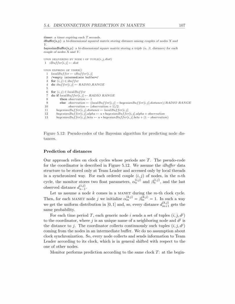
5.4. DISCONNECTION PREDICTION IN MANETS 107
timer: a timer expiring each T seconds.iBuffer[x,y]: a bi-dimensional squared matrix storing distance among couples of nodes X andY.bayesianBuffer[x,y]: a bi-dimensional square matrix storing a triple (α, β, distance) for eachcouple of nodes X and Y.
upon delivering by node i of tuple(i, j, dist)1 iBuffer[i, j] ← dist
upon expiring of timer()1 localBuffer ← iBuffer[i, j]2 /*empty intermediate buffer*/
3 for (i, j) ∈ ibuffer4 do ibuffer[i, j] ← RADIO RANGE56 for (i, j) ∈ localBuffer7 do if localBuffer[i, j] ← RADIO RANGE8 then observation ← 19 else observation ← (localBuffer[i, j]− bayesianBuffer[i, j].distance)/RADIO RANGE
10 observation ← (observation + 1)/211 bayesianBuffer[i, j].distance ← localBuffer[i, j]12 bayesianBuffer[i, j].alpha ← u ∗ bayesianBuffer[i, j].alpha + observation13 bayesianBuffer[i, j].beta ← u ∗ bayesianBuffer[i, j].beta + (1− observation)
Figure 5.12: Pseudo-codes of the Bayesian algorithm for predicting node dis-tances.
Prediction of distances
Our approach relies on clock cycles whose periods are T . The pseudo-codefor the coordinator is described in Figure 5.12. We assume the iBuffer datastructure to be stored only at Team Leader and accessed only by local threadsin a synchronized way. For each ordered couple (i, j) of nodes, in the n-thcycle, the monitor stores two float parameters, α
(i,j)n and β
(i,j)n , and the last
observed distance d(i,j)n−1.
Let us assume a node k comes in a manet during the m-th clock cycle.Then, for each manet node j we initialize α
(k,j)m = β
(k,j)m = 1. In such a way
we get the uniform distribution in [0, 1] and, so, every distance d(k,j)m+1 gets the
same probability.For each time period T , each generic node i sends a set of tuples (i, j, dj)
to the coordinator, where j is an unique name of a neighboring node and dj isthe distance to j. The coordinator collects continuously such tuples (i, j, dj)coming from the nodes in an intermediate buffer. We do no assumption aboutclock synchronization. So, every node collects and sends information to TeamLeader according to its clock, which is in general shifted with respect to theone of other nodes.
Monitor performs prediction according to the same clock T : at the begin-

108 CHAPTER 5. THE SMARTPM SYSTEM
ning of the generic n-th clock cycle upon timer expiring, it copies the tuples(i, j, dj
n) from the intermediate buffer to another one and, then, it empties theformer buffer to get ready for updated values. In the clock cycle, for each col-lected tuple (i, j, dj) monitor updates the parameters as follow by a bayesianfilter:
{α
(i,j)n+1 = u · α(i,j)
n + o(i,j)n
β(i,j)n+1 = u · β(i,j)
n + (1− o(i,j)n )
(5.17)
where o(i,j)n is an observation and u ∈ [0, 1] is a constant value. Constant
u aims for permitting old observations to age. As new observations arrive,the previous ones get less and less relevance. Indeed, old observations do notcapture the updated status of manet connectivity and motion.
The value for observation can be computed from the relative distance vari-ation between i and j, scaled with radio-range:
∆dr(i,j)n =
d(i,j)n − d
(i,j)n−1
radio range(5.18)
where radio range is the maximum distance from where two nodes can com-municate with each other.
Possibly d(i,j)n can miss in the cycle n. The distance between i and j could
miss because i and j are not in radio-range or packets sent by i to Team Leaderare lost or delivered lately.
It is straightforward to prove ∆dr(i,j)n to range in [-1, 1] interval. This
range is not suitable for Bayesian filter since observations should be between0 and 1. So we map the value in Equation 5.18 into the suitable range [0, 1]as follows16:
o(i,j)n =
d(i,j)n −d
(i,j)n−1
radio rangedn and dn−1 are available
1 if dn is unavailable12
if dn is available but dn−1 is not
(5.19)
In sum, our Bayesian approach estimates the variation of the future dis-tance between every couple of nodes, normalized in the [0, 1] range. Valuesgreater than 0.5 mean nodes to drift apart and smaller values to move closer.If the value is equal to 0.5, node i is estimated not to move with respect to j.
The parameters α and β are the inputs for Beta distribution Beta(α, β),where the expectation θ
(i,j)n+1 = E
(Beta(α(i,j)
n+1, β(i,j)n+1)
)is the variation of the dis-
tance between i and j in radio-range percentage that will be estimated at thebeginning of (n + 1)-th clock cycle.
16If a node has entered in this cycle we assume o(i,j)n = 0.5, i.e., it is not moving.

5.4. DISCONNECTION PREDICTION IN MANETS 109
At this stage we can estimate the distance between nodes i and j at thebeginning of (n + 1)-th clock cycle. That can be done from Equation 5.19 byreplacing the observation term o
(i,j)n with the estimated value θ
(i,j)n+1. Hence:
d(i,j)n+1 = d
(i,j)n + ∆d
(i,j)
n == d
(i,j)n + (2θ(i,j) − 1) ∗ radio range
(5.20)
It should hold d(i,j)n = d
(j,i)n ; so, it should be d
(i,j)n+1 = d
(j,i)n+1. But we have
to consider d(i,j)n+1 6= d
(j,i)n+1. Indeed distance sent by i about distance (i, j) can
differ from what is sent by j about the same distance. This is why distancesare collected at beginning of clock cycles but these can be shifted. Indeed,information can be different, as collected in different moments.
Therefore, estimated distance di,jn+1 is computed by considering both di,j
n+1
and d(i,j)n+1, through different weights.
di,jn+1 = rel
(i,j)n+1 ∗ d
(i,j)n+1 + rel
(j,i)n+1 ∗ d
(j,i)n+1
where rel(i,j)n+1 is a factor for the estimation re-
liability and it is inversely proportional to
σ(i,j)n+1 =
√V ar(Beta
(α
(i,j)n+1, β
(i,j)n+1)
):
rel(i,j)n+1 =
1
σ(i,j)n+1
1
σ(i,j)n+1
+ 1
σ(j,i)n+1
=σ
(j,i)n+1
σ(i,j)n+1 + σ
(j,i)n+1
.
Connected Components Computation
Disconnection prediction depends on a parameter γ, which stands for thefraction of the radio-range for which the predictive technique doesn’t signal adisconnection anomaly17. Let be P (disc
(i,j)n+1) = P (d(i,j)
n+1 ≥ γradio range); twonodes i and j are predicted going to disconnect if and only if
rel(i,j)n+1 ∗ P (disc
(i,j)n+1) + rel
(j,i)n+1 ∗ P (disc
(j,i)n+1) >
12
(5.21)
i.e. two nodes i and j are estimated disconnecting if it is more probable theirdistance to be greater than γradio range rather than distance to be smallerthan such a value. We could tune more conservativeness by lowing γ (i.e.
17As an example, in IEEE 802.11 with 100 meters of radio-range, γ equal to 0.7 meansthat for a communication distance of 70 meters the prediction algorithm signals a probabledisconnection.

110 CHAPTER 5. THE SMARTPM SYSTEM
the fraction of radio-range in which disconnections are not predicted). If weconsider Equation 5.20, then:
P (disc(i,j)n+1) = P (
∣∣ d(i,j)n
radio range + (2θ(i,j) − 1)∣∣ ≥ γ)
= P(θ(i,j) ≥ 1+γ
2 − d(i,j)n
2∗radio range
) (5.22)
where the last term in Equation 5.22 is directly computable from the estimatedbeta distribution:
P (θ(i,j) > k) =∫ 1
kBeta
(α(i,j), β(i,j)
)
Once the algorithm predicts which links exist at the next cycle, we can com-pute easily the connected components (i.e., sets of nodes that are predicted tobe connected). Afterwards, on the basis of the connected components, discon-nection anomalies are identified by the monitor. Connected components arecomputable through “The Mobile Gamblers Ruin Algorithm” below, where anedge between couples of nodes in the connection graph exists if Equation 5.21is false.
Note that an error could be introduced by techniques for communicationdistance evaluation: as our model is based on a Markov chain made of com-munication distances between devices, and since the measured distances couldinclude an approximation error compared to real communication distances,this error could affect our model. Let’s assume that for every St
(i,j) there isan average error 4S introduced by the real measure. Thus, by observing thatour model is linear, it follows that the 4S is spread all over the measures butdoesn’t depend on t, so S
(t+1)p(i,j)
is actually S(t+1)p(i,j)
±4S. Indeed, the exact valueof 4S depends on which technique is used for distances evaluation, but as itis typically small compared to S
(t+1)p(i,j)
, then our average error on the predictionmodel is only partially affected by this error.
The “The Mobile Gambler’s Ruin” (MGR) algorithm is derived from theMarkov chain model of the well-known gambler’s ruin problem [47, 62]. Sucha study of the device movements and the consequent distance prediction isbased on Markov chains, because the success of a prediction depends only onevents of previous time frame units. Instead of using a markovian process intime domain, we are going to focalize on spatial domain and we will build amatrix, which is similar to the one presented in the original gambler’s ruinmodel but with other elements.
Let’s consider a square matrix of |E| × |E| elements, where |E| = m,with m, with m is the total number of mobile devices in the manet. Webuild M = (mij) as a m × m symmetric matrix, in which mij = 1 isthe Equation 5.21 is false or, otherwise mij = 0 if the equation is true18.
18The matrix is of course symmetric since always there holds mij = mji

5.4. DISCONNECTION PREDICTION IN MANETS 111
FUNCTION MGR()1 numcomps ← 02 Comps ← newArray of integer[m];3 for i ← 0 to (m− 1)4 do if Comps[i] = 05 then numcomps ← numcomps + 16 Comps[i] ← numcomps7 CCDFSG(M, i, numcomps, Comps[])8 return Comps[]
SUB CCDFSG(M, i, numcomps, Comps[])1 for i ← 0 to (m− 1)2 do if Comps[j] = 0 and M [i, j] = 13 then numcomps ← numcomps + 14 CCDFSG(M, j, numcomps, Comps[])5
FUNCTION TEST CONNECTION(i, j, Comps[])1 if Comps[i] = Comps[j]2 then TEST ← true3 else TEST ← false4 return TEST
Figure 5.13: Pseudo-Code of the MGR algorithm.
Every diagonal element mii = 1 since the P (disc(i,j)n+1) = P (disc
(j,i)n+1) = 0.
That follows for definition: the distance of a mobile device from itself is alwaysequal to 0.
The matrix M = (mij) can be considered as the Adjacency matrix ofan (undirected) graph where the set of nodes are devices and an arc existsbetween two nodes if they are foreseen as direct neighbors.
The strategy of the MGR algorithm, which is described in Figure 5.4.2, is tofind the connected components of the graph (using the CCDFSG procedure),and then, by giving two devices ei and ej , to verify if they belong to thesame connected component (the TEST CONNECTION function); if it istrue then ei, ej will still communicate in the next time period; else they willlose their connection within the next time period. Using this strategy, afterbuilding the matrix M = (mij), we can verify which devices are connected,directly (i.e., one hop) or indirectly (i.e., multi hop), and thus let decide whendisconnection management techniques should be activated in order to keep theconnection between the involved devices. The aim of such techniques shouldbe to have a unique connected component in the graph.
The MGR algorithm computes the connected components starting fromthe matrix that represents the graph. The output of the MGR programis the Comps array in which for each i-th element there is an integer valuecorresponding to the connected component it belongs. For example, if wehave a set of devices E = {e1, ..., em} and they form a graph with k connected

112 CHAPTER 5. THE SMARTPM SYSTEM
Process Management System
Coordinator Device Generic Peer
it.uniroma1.dis.Octopus
BayesianPredClient
BayesianBuffer
BayesianTuple
Buffer
DistanceServer
PredictiveTimer
0..*
BayesianPredServer
TCP/IP Sockets
Information About Neighbors
PMS Manager
Prediction Manager Manager
Disconnection Signalling
Figure 5.14: The components of the actual implementation.
components, we will have an output vector of this shape:(0 0 . . . 1 . . . 2 . . . k − 1
)(5.23)
Thus for two different devices ei, ej we have only to test, using theTEST CONNECTION program, if they have the same value in the vector(5.23), It will give us a confidence about the probability of being still con-nected in the next time period.
5.4.3 Technical Details
We implemented the Bayesian algorithm on actual devices. We coded in MSVisual C# .NET as it enables to write applications once and deploy themon any device for which a .NET framework exists (PCs and PDAs included).In this section, we describe the technical details of packages and classes forimplementing the Bayesian algorithm.
We can identify two sides in the implementation as described in Figure 5.14:the code running on the coordinator device, which realizes the prediction,and that on the generic peers sending information about neighbors to thecoordinator.
The code of generic peers is conceptually easy. It is basically composed oftwo modules:
it.uniroma1.dis.Octopus. We tested our algorithm by the octopus virtualenvironment described in Section 5.5. octopus is intended to emulate

5.4. DISCONNECTION PREDICTION IN MANETS 113
small manet and holds a virtual map of the are where nodes are ar-ranged. This module is intended to query octopus for knowing nodeneighbors and their distance.
BayesianPredClient. This module includes internally two timers. The firsttimer has a clock T, where T is the same as defined in Figure 6.1. Foreach clock period, it gets information about neighbors (who and howfar they are) by using the it.uniroma1.dis.Octopus module. Then, itarranges such an information in a proper packet, which is sent to coordi-nator. Upon expiring of the second timer, the client sends a command tooctopus to change the position of the node which this device is mappedto. Of course, this timer uses also the it.uniroma1.dis.Octopus module.
The core of the coordinator predictor is the BayesianPredServer module. Inthe specific case, it worthy breaking it down in the composing classes:
DistanceServer. This module implements a TCP/IP server to retrieve theneighboring information from peers (sent by them through the moduleBayesianPredClient). At the same time, it stores retrieved informationin the intermediate buffer, which is implemented by the module Buffer.It corresponds to event handler for upon delivering of a tuple from apeer as defined in Figure 6.1.
Buffer. It implements the intermediate buffer module, written by the Dis-tanceServer module and read/made empty by PredictiveTimer. Thismodule guarantees synchronized accesses.
PredictiveTimer. This is a timer that repeats each T seconds. It imple-ments the event upon expiring of timer as defined in Figure 6.1. Con-sistently to the pseudo-code, it accesses to the Buffer module to getnew information from other peers, as well as the BayesianBuffer mod-ule. The latter module stores the information to compute for eachcouple of nodes the Equations 5.17 e 5.19. This module uses also theit.dis.uniroma1.Octopus module. Indeed, Team Leader is a node itselfand it can lead to disconnections. Therefore, it has to ask for neighborsto octopus and predict distances to any other node.
BayesianBuffer, BayesianTuple. The BayesianBuffer class handles andstores the triple
(α(i,j),β(i,j),d(i,j)
), each one represented by a
BayesianTuple object.
A second module composes the coordinator architecture and is namedPMSManager. It is in charge of communicating with the proper device man-agement of the SmartPM engine to inform when disconnections are predicted

114 CHAPTER 5. THE SMARTPM SYSTEM
by module BayesianPredServer, specifically by using class PredictiveTimer.The device manager, in its turn, will generate an appropriate exogenous ac-tion disconnect(·) to inform the IndiGolog engine about the disconnection.
5.4.4 Experiments
We conclude the section of the bayesian algorithm for disconnection predictionby giving the result of some experiments performed for the sake of verifyingthe accuracy of predictions. Therefore, testing does not involve the SmartPMadaptive PMS.
In order to test the implementation, we used emulation by octopus (seeSection 5.5). This allows to test the feasibility of an actual implementationbeyond the theoretical soundness of the approach. octopus keeps a map ofvirtual areas, which users can design and show by a GUI. Such a GUI enablesthe users to put in that map the virtual nodes and bind each one to a differentreal device. Furthermore, users can add possible existing obstacles in a realscenario: ruins, walls and buildings.
The test-bed consists of nine machines (PCs and PDAs). In addition tothese, there is a further PC that hosts the octopus virtual environment. Eachof the nine machines is bound to a different virtual node of octopus’ virtualmap.
We set the testing virtual map as 400 × 300 meters wide and communica-tion radio-range as 100 meters. At the beginning, nodes are located into thevirtual map in a random fashion in order to form one connected component.Afterwards, each S seconds, every node chooses a point (X,Y ) in the mapand begin heading towards at a speed of V m/s. Both S and V are Gaussianrandom variables: the mean and variance are set as, respectively, 450 and 40seconds for S and 3 and 1.5 m/s for V . The couple (X,Y ) is chosen uni-formly at random in the virtual map. Of course, devices used in tests do notmove actually: nodes move only in the virtual map. For this purpose, devicessend particular commands to a specific octopus socket for instructing nodemotions.
The first set of experiments has been intended to verify which error inpercentage is obtained for different values of clock period T . The error hereis defined as the gap between the estimated distances dn at (n − 1)-th clockcycle and the actual measures dn at n-th clock cycle. The value is scaled withrespect to the radio-range:
The Figure 5.15(a) shows the outcome for the clock periods equal to 15,20, 30, and 45 seconds. We have set the parameter u of Equation 5.17 tovalue 0.5 and performed ten tests per clock period. Every test was 30 minuteslong. The results show, of course, that the error percentage grows high asclock period increases. Probably the most reasonable value for real scenarios

5.4. DISCONNECTION PREDICTION IN MANETS 115
0,00%
2,50%
5,00%
7,50%
10,00%
12,50%
15,00%
17,50%
20,00%
22,50%
25,00%
15 20 30 45
Polling time
Th
e er
ror
per
cen
tag
e
Best Case
Worst Case
(a) The smallest and largest measured error in percentage,changing clock periods.
20,30%
19,55%
19,02%
18,09%
17,44%17,59%
18,28%
19,03%
19,94%
21,53%
17,00%
17,50%
18,00%
18,50%
19,00%
19,50%
20,00%
20,50%
21,00%
21,50%
22,00%
0 0,1 0,2 0,3 0,4 0,5 0,6 0,7 0,8 0,9
u
Th
e er
ror
per
cen
tag
e
(b) The measured error in percentage, changing the weight ofpast observations.
Figure 5.15: Experiment results of the disconnection prediction module.

116 CHAPTER 5. THE SMARTPM SYSTEM
is 30–45 seconds (smaller values are not practically feasible since manetswould be probably overloaded by “distance” messages). Please consider thegreatest clock period we tested: the error ranges between 24.34% and 26.8%(i.e., roughly 25 meters).
Afterwards, in a second tests set, we fixed clock period to 30 seconds,testing for u equal to 0.01, 0.05, 0.1, 0.2, . . . , 0.8. We even tripled the frequencywhich nodes start moving with. The outcomes are depicted in Figure 5.15(b),where x-axis corresponds to u values and y-axis to the error percentage. Thetrend is parabolic: the minimum is obtained for u = 0.3 where the error is17.44% and the maximum is for u = 0.8 where the error is 21.54%. Smallvalues for u mean that the past is scarcely considered whereas large valuesmean the past is strongly taken into account. This matches our expectation:we get the best results for the intermediate values. That is to say that thebest tuning is obtained when we consider the past neither too little nor toomuch.
As far as SmartPM and other possible applications, they can rely on suchpredictions. Indeed, setting polling time to 30 seconds, we have got errorsaround 18% for u = 0.3. If range is supposed to be 100 meters, the meanerror is around 18 meters. Indeed, if we set γ = 0.75 (i.e., disconnectionsare predicted when nodes are more than 75 meters far away), we would besure to predict every actual disconnection. That means no disconnection isnot handled, although coordination layer (distributed or centralized, local orglobal) will be alerted about some false negatives, enacting recovery actionsto handle unreal disconnections.
5.5 The OCTOPUS Virtual Environment
This section turns to describe an emulator, namely octopus, that we de-veloped with the purpose of testing SmartPM in pervasive scenarios by usingmanet. Indeed, when developing any software system (including SmartPM),it is needed to study alternatives for the design and implementation of soft-ware modules, analyze possible trade-offs and verify whether specific protocols,algorithms and applications are actually working. There exist three way toperform analysis and tests: (i) simulation, (ii) emulation and (iii) field tests.
Clearly on-field tests would be the most preferred solution, but they re-quire many people moving around in large areas and repeatability of the ex-periments would be compromised. Simulation and emulation allow to performseveral experiments in a cheaper and more manageable fashion than field tests.Simulator and emulator (i.e., hardware and/or software components enablingsimulation or emulation) do not exclude each other. Simulation can be usedat an earlier stage: it enables to test algorithms and evaluate their perfor-

5.5. THE OCTOPUS VIRTUAL ENVIRONMENT 117
mance before starting actually implementing on real devices. Simulators, suchas NS219 [112], GlomoSim [147] or OMNeT++ [126], allow for several kindsof hardware, through appropriate software modules (such as different devicetypes, like PDAs or smartphones, or networks, like Ethernet or WLAN 802.11).Even if the application code written on top of simulators can be quickly writ-ten and performances easily evaluated, such a code must be throw out andrewritten when developers want to migrate on real devices.
The emulators’ approach is quite different: during emulation, some soft-ware or hardware pieces are not real whereas others are exactly the ones onactual systems. All emulators (for instance, MS Virtual PC or PDA emulatorin MS Visual Studio .NET) share the same idea: software systems are notaware of being working on some layers that are partially or totally emulated.On the other hand, performance levels can be worse: operating systems run-ning on Microsoft Virtual PC work slower than on a real PC with the samecharacteristics. Anyway, software running on emulators can be deployed onactual systems with very few or no changes.
On the basis of such considerations, we developed octopus, a completeemulator environment for manets.20 Our emulator is intended to emulatesmall scale manets (10-20 nodes). Instead of making the whole manet stackvirtual, which would require duplication of a large amount of code, we de-cided to emulate only the physical MAC layer, leaving the rest of the stackuntouched. octopus keeps a map of virtual areas that users can show anddesign by a GUI. Such a GUI enables users to put in that map virtual nodesand bind each one to a different real device. Further, users can add possibleexisting obstacles in a real scenario: ruins, walls, buildings.
The result is that real devices are unaware of octopus: they believe tosend packets to destinations. Actually, packets are captured by octopus,playing the role of a gateway. The emulator analyzes the sender and thereceiver and takes into account the distances of corresponding virtual nodes,the probability of losses as well as obstacles screening direct view21. On thebasis of such information, it decides whether to deliver the packet to thereceiver.
The advantage of octopus is that, in any moment, programmers canremove it and perform field manet tests without any kind of change. The aimhere is to present octopus and its novel features. Later we investigate existingsolutions by taking into account several comparing dimensions, specifically:
Minimal initial effort. The time amount necessary to learn and start us-
19NS2 enables both simulation and emulation. Here, we refer to NS2’s simulation features.20octopus can be downloaded at: http://www.dis.uniroma1.it/∼deleoni/Octopus.21We assume whenever two nodes are not directly visible, every packet sent from one node
to the other one is dropped.

118 CHAPTER 5. THE SMARTPM SYSTEM
ing the emulator. Several emulators require to write complex scripts tomodel channels in detail. We are interested in algorithms for the appli-cation layer (and not for the network one), whose performances are onlyslightly modified by the channel and network parameters.
Portability. This feature gets a twofold meaning: from one hand, it meanscode to be ported in non-emulated environments with few or no changes.From the other hand, we refer portability as the ability to enable, dur-ing emulation, the use of several platforms, such as PCs with Linux orWindows and PDAs with Windows CE or PalmOS.
Handling of Obstacles. The virtual map, which emulator holds, should al-low users to insert obstacles representing walls, ruins, buildings. Virtualnodes should move into the map by passing around without going oversuch obstacles. Movements should be as realistic as possible, accordingto well-know patterns.
Run-time Event Support. During experiments, destinations of the nodesare required to be defined at run-time, according to the behavior of clientapplications. Essentially, movements cannot be defined in a batch way;conversely, during emulations, nodes have to interactively inform theemulator about the movement towards given destinations.
As of our knowledge, octopus is the first manet emulator enabling clientsto interactively influence changes in the topology, upon firing of events whichwere not defined before the beginning of the emulation. Other emulatorsrequire the specification in batch mode, i.e., when the emulation is not yetstarted, of which and when events fire.
In addition, octopus allows to include any kind of device, even PDAs orsmartphones, and applications, whereas other approaches support only someplatforms or applications coded in specific languages. Finally, octopus sup-ports and handles possible obstacles, packet losses and enhanced movementmodels, like Voronoi [69].
Please note that, though octopus was built for testing SmartPM, its ap-plicability is broader and comprises all software systems that developers arewilling to test on manet without having to write some code that is thrownaway after the experiments.
5.5.1 Related Work
There exist several mobile emulators in the literature, even if they do notprovide the features which we need for our intends.
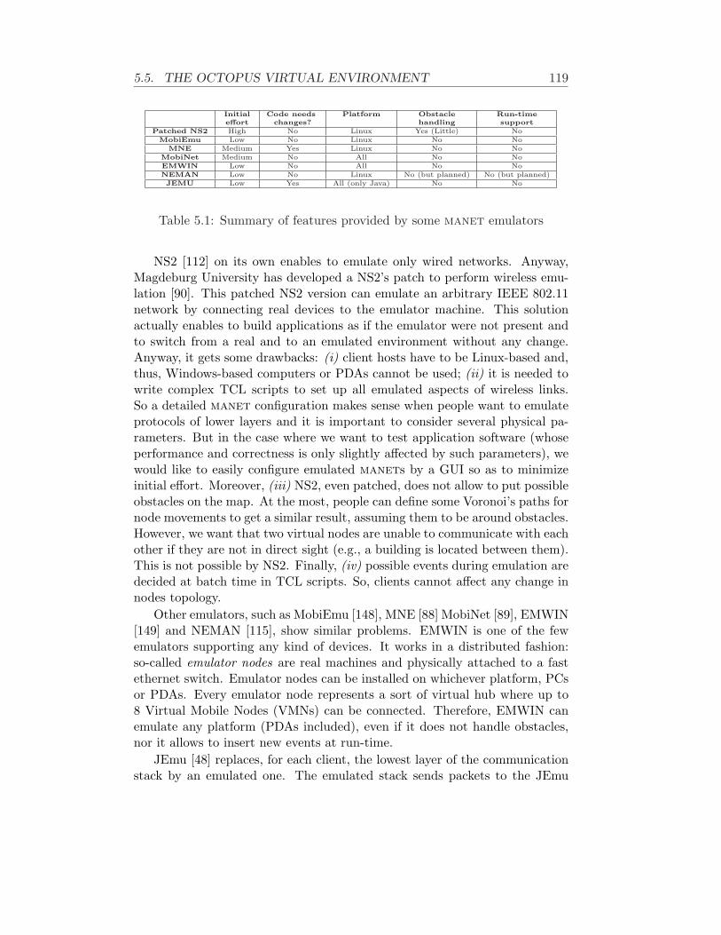
5.5. THE OCTOPUS VIRTUAL ENVIRONMENT 119
Initial Code needs Platform Obstacle Run-timeeffort changes? handling support
Patched NS2 High No Linux Yes (Little) NoMobiEmu Low No Linux No No
MNE Medium Yes Linux No NoMobiNet Medium No All No NoEMWIN Low No All No NoNEMAN Low No Linux No (but planned) No (but planned)JEMU Low Yes All (only Java) No No
Table 5.1: Summary of features provided by some manet emulators
NS2 [112] on its own enables to emulate only wired networks. Anyway,Magdeburg University has developed a NS2’s patch to perform wireless emu-lation [90]. This patched NS2 version can emulate an arbitrary IEEE 802.11network by connecting real devices to the emulator machine. This solutionactually enables to build applications as if the emulator were not present andto switch from a real and to an emulated environment without any change.Anyway, it gets some drawbacks: (i) client hosts have to be Linux-based and,thus, Windows-based computers or PDAs cannot be used; (ii) it is needed towrite complex TCL scripts to set up all emulated aspects of wireless links.So a detailed manet configuration makes sense when people want to emulateprotocols of lower layers and it is important to consider several physical pa-rameters. But in the case where we want to test application software (whoseperformance and correctness is only slightly affected by such parameters), wewould like to easily configure emulated manets by a GUI so as to minimizeinitial effort. Moreover, (iii) NS2, even patched, does not allow to put possibleobstacles on the map. At the most, people can define some Voronoi’s paths fornode movements to get a similar result, assuming them to be around obstacles.However, we want that two virtual nodes are unable to communicate with eachother if they are not in direct sight (e.g., a building is located between them).This is not possible by NS2. Finally, (iv) possible events during emulation aredecided at batch time in TCL scripts. So, clients cannot affect any change innodes topology.
Other emulators, such as MobiEmu [148], MNE [88] MobiNet [89], EMWIN[149] and NEMAN [115], show similar problems. EMWIN is one of the fewemulators supporting any kind of devices. It works in a distributed fashion:so-called emulator nodes are real machines and physically attached to a fastethernet switch. Emulator nodes can be installed on whichever platform, PCsor PDAs. Every emulator node represents a sort of virtual hub where up to8 Virtual Mobile Nodes (VMNs) can be connected. Therefore, EMWIN canemulate any platform (PDAs included), even if it does not handle obstacles,nor it allows to insert new events at run-time.
JEmu [48] replaces, for each client, the lowest layer of the communicationstack by an emulated one. The emulated stack sends packets to the JEmu

120 CHAPTER 5. THE SMARTPM SYSTEM
server. It decides, taking into account certain information (e.g., distance,collision, etc.) whether the actual destination can receive them (even if ostaclesare not handled). If so, the emulator forwards these packets to the JEmu clientof the receiver. JEmu is totally written in Java so it works only with Javasoftware. Furthermore, applications need many changes if emulated by JEmu.
Table 5.1 summarizes the features which we are interested in for octopus.In this table, “Patched NS2” refers to NS2 enhanced by Madgeburg’s patch.Its “Little” obstacle support means that people might define Voronoi’s pathsfor node movements, assuming paths to be around obstacles. The NEMANentries referred as “planned” are the features which authors will implementin future releases: specifically they plan in future to handle obstacles and toenable applications to influence at run-time links topology.
As you can see from the table, no emulator allows applications to mod-ify at run-time nodes topology. All emulators are based on the same wayof using: at design-time, possibly through a GUI, users set up the scenarioand a virtual map, binding virtual wireless nodes to real devices, as well asthe moments when events fire, such as reaching a given position. Afterwards,applications are running on devices to be emulated. When such a prepara-tion phase finishes, emulation starts and events fire according to the specifiedschedule. We want to enable the firing of events which were unforeseen duringthe arrangement of emulation scenarios. In the “real world” the events, suchas movements, are caused by users, which interact with applications on boardof devices. In general, and especially when testing novel prototypes of applica-tion software on top of manets, applications on devices may influence the linktopology and nodes motion (e.g., when executing tasks, devices . Thereforebatch emulations might be completely useless. Moreover, obstacles are nothandled by other emulators. We think that these aspects are important tomake emulations realistic. So, we introduced such novel features in octopus.
5.5.2 Functionalities and Models
octopus provides functionalities to emulate a wireless local area network byan intuitive and user friendly graphic interface. Main features provided byoctopus are described as follows:
Integrated graphical scenario editor. Emulation scenario setup is fullymanaged through a GUI and there is no need to know or use any script-ing language at all. This choice has been made to allow the averageuser, even with only basic network knowledge, to focus mainly on theexperimental aspects.
Real time node mobility management. In our target experiments, desti-nations that nodes want to reach, have to be defined at run-time, accord-

5.5. THE OCTOPUS VIRTUAL ENVIRONMENT 121
ing to the behavior of client applications. Essentially, movements cannotbe defined in a batch way before emulation starts; on the contrary, duringemulations, nodes have to somehow inform emulator about their move-ments towards a given destination22. This feature is implemented as aTCP server listening for special “movement” commands sent by softwareon board of devices. We know this breaks our constraint, which statessoftware on devices do not have to be modified when removing emulator.Anyway, changes, if any, are extremely bounded. Basically they consistin “commenting” invocations to octopus. In this case we could notavoid to violate it: since those events are generated at run-time by soft-ware on devices, only such software can send those commands. However,if we do not need this feature, software on devices actually does not haveto be modified when the emulator is removed.
Packets losses. The emulation system supports user-defined packet loss poli-cies, described by a customizable range based function pd(r). The func-tion pd(r) = k means the probability of a packet sent by a node to bedelivered to a node r-meters far is k. octopus supports also a moreadvanced modelling of packet loss based on the ricean fading, which isalso more compliant with the real behaviour of a wireless communicationchannels. Section 5.5.2 gives more details.
Obstacle-aware mobility model. Two movement models are available inoctopus: Way-Point and Voronoi [69]. The first one assumes nodes tomove straight on the line joining starting and destination point. Thelatter is more realistic and it takes into account even possible obstaclesalong the path. The devised algorithm is based by the Voronoi planetessellation model. Section 5.5.2 gives more detail about this algorithm.
Broadcast address emulation support. In some algorithms, we maywant peers to broadcast a message to every peer in radio range. Sincedevices are connected through a real LAN23, we cannot use the normalbroadcast IP address (i.e., x.x.x.255), as it would send the packet toall peers in the network without considering the routing table. We wantto broadcast only to virtual neighbors. This issue is resolved by addinga customizable virtual broadcast address instead of the usual one.
In the following, some details of octopus are given.
22This makes sense when behavior of client applications is controlled by humans.23octopus and other actual devices have to be deployed in the same LAN in order to have
octopus to be able to reach other devices.

122 CHAPTER 5. THE SMARTPM SYSTEM
Voronoi Mobility Model
In order to develop a realistic mobility management, the nodes, living in theemulated environment, move avoiding obstacles. As a matter of fact, humansfollow predefined paths to reach a place, such as roads and sidewalks: emu-lated environments should show similar behaviors. octopus allows to definepolygonal obstacles in the virtual map and it generates the graph of all possi-ble segments of paths that do not cross them. The algorithm we have devisedderives from Original Voronoi algorithm. Original Voronoi assumes to havea given set P of points in the plane and builds some special lines. Voronoi’slines describe closed polygons in the plane. Each polygons includes exactlyone pi ∈ P of the original points. For each pi, the corresponding polygoncontains all points which are closer to pi than other pj ∈ P .
Since obstacles are polygons and not simply points, a generalization isneeded:
1. Generate a “sampled” version of every obstacle by sampling every sideof every obstacle and replacing each one with a sequence of points. Thesampling rate can be defined by users.
2. Generate Voronoi diagram by considering points generated at point 1.
3. Remove segments crossing one or more obstacles. That means all seg-ments having at least one of the two vertices inside an obstacle areremoved.
octopus Voronoi diagram is computed as dual of Delaunay triangulation[55], as it gets actually lower realization complexity. Each segment generatedby the Voronoi algorithm represents a possible part of the path that nodes areforced to follow in order to move without crossing an obstacle.
Packet Loss Models
In order to model the packet losses due to the unreliability of the physicalchannel, octopus comes with two channel models. A first model relies on thedefinition of a customized function; a second is based on the ricean fading.
Customized packet loss function. The first model concerns the possibil-ity of advanced users to define their own loss function pd(r). The modellingof a loss function tells which is the probability of delivering a packet when thepossible receiver is far away from the send r meters. For instance, users canmodel perfect reliability by defining pd(r) = 1 ∀r ∈ [0, rrange], where rrangeis the radio range of the specific transmission technology, e.g., 100 meters forIEEE 802.11b/g and 10 meters for Bluetooth.

5.5. THE OCTOPUS VIRTUAL ENVIRONMENT 123
Since obstacles are present in the virtual area, we assume radio signal donot pass through obstacles; this means that each packet sent by a node toanother is surely dropped if the couple of nodes is not in direct sight. In thereal world, a wireless device may measure its distance to the others by signal tonoise ratio (SNR) techniques: the higher is the physical distance, the higher isthe noise in communication channel and, hence, SNR. However, that gives anapproximate “communication distance” between two peers: this method doesnot give the exact physical distance for other factors, such as thin obstaclesamong devices or other interferences, which can cause noise incrementing.So, communication distance dem
c and real distance demr may differ. It is too
difficult (and perhaps even impossible) to emulate physical factors affectingcommunication distance. Therefore, octopus define communication distancebetween two nodes a and b as follow:
demc (a, b) =
{dem
r (a, b) if nodes are in direct sight∞ if at least one obstacle divides a and b
The probability to deliver a packet is given by evaluating the user defined lossfunction where input is dem
c . So, the probability to deliver to a node b a packetsent by a node a:
pa,b = pd(demc (a, b)) ∈ [0, 1]
When a wants actually to send a packet to b, octopus computes pa,b. Then,it generates a random value x ∈ [0, 1] from an uniform distribution. Finally,octopus follows the rule “if x ≤ pa,b then deliver else drop” to decidewhether such a packet has to be delivered or dropped.
Ricean Fading. A second way octopus feature to model packet losses isbased on the ricean fading extensively used to model wireless channels. Ricianfading is a stochastic model for radio propagation anomaly caused by partialcancellation of a radio signal by itself [104]. These anomalies are generate dueto small changes the elements in the environments where the wireless signalhas to propagate (e.g., objects changing their position, people moving in thearea, doors or windows opening or closing). In such situations, the signalarrives at the receiver by different paths in different points in time, and suchdifferent “versions” interfere with each other. Here we do not want to detailmore how the channel has been modeled to take Ricean Fading into account. Itis only worthy telling the reduction of the signal strength (and, consequently,the probability of packet losses) when the distance is r is characterized by theRicean Distribution:
f(r) =r
σ2· exp−
x2+ν2
2σ2 ·I0
(xν
σ2
)
where ν and σ are two parameters that are depending on some aspects of thechannel of interest.
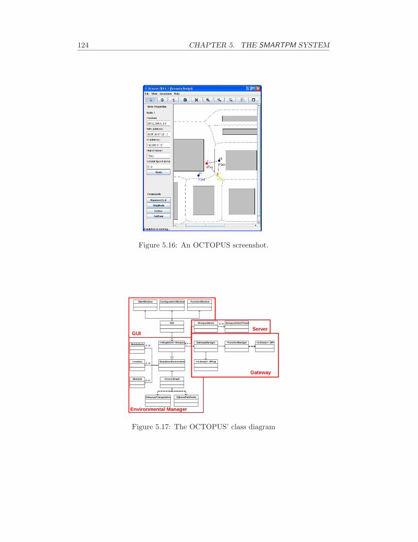
124 CHAPTER 5. THE SMARTPM SYSTEM
Figure 5.16: An OCTOPUS screenshot.
GatewayManager
OctopusServerGUI
SimulationEnvironment
<<Singleton>> OctopusMobileNode
Obstacle
Location
0..N
0..N
0..N
FunctionManager <<Library>> JEP
<<Library>> JPCap
VoronoiGraph
DelaunayTriangulation DijkstraPathfinder
MainWindow ConfigurationWindow FunctionWindow
OctopusClientThread0..N
GUIServer
Gateway
Environmental Manager
Figure 5.17: The OCTOPUS’ class diagram

5.5. THE OCTOPUS VIRTUAL ENVIRONMENT 125
5.5.3 The OCTOPUS Architecture
octopus is completely written in Java; in particular, it has been tested bothon Windows and on Linux. The octopus architecture relies basically on fourmodules:
Environment Manager. It is the core module and the octopus’ behaviordepends on its setting. Users can setup several parameters, such as areasize, node positions, radio ranges and obstacles. It also computes theVoronoi’s graph. This module is used by the Gateway module to getinformation to learn whether a packet has to be delivered or not.
Gateway. octopus plays the role of a gateway: this module intercepts allpackets sent by nodes involved in the emulation and addresses every net-work issue. It decides whether to forward by taking into account distanceinformation from the Environment Manager. The Gateway module im-plements the packet dropping policy described in 5.5.2.
Server. This module implements the TCP Server, listening on the 8888 port.Such a server is intended to receive command from applications aboutevents (like movements) to trigger and to reply to queries coming fromclients. For instance, a client could ask which are neighbors or which isthe distance from them. The communication protocol is a trivial textualprotocol. We have also realized a C# module masking socket accessesbehind an easy API.
GUI. In order to minimize the effort to setup initial scenario and bind virtualnodes to the actual devices, octopus is provided with a Graphical UserInterface. It enables to perform any configuration aspect in a friendlyfashion, without having users to learn any special scripting language.At design-time users can insert in the virtual area nodes, obstacles andbuildings by “point-and-click”, as in any drawing software. GUI allowsusers to load/save scenarios and settings from/to XML files without hav-ing to setup every time scenarios from scratch. At run-time, GUI showsthe exact position of virtual nodes in the maps. Figure 5.16 depicts anoctopus screenshot: the right panel shows the virtual area, whereas thetop part is used at design-time to configure scenarios (nodes, positions,etc.) The left panel describes the nodes mappings and other information,allowing, also, users to change position of nodes by firing manually someevents. The gray rectangles and lines represent, respectively, obstaclesand Voronoi lines, which nodes follow during motions. If a proper optionis active (as it is in the figure), the GUI shows virtual neighbor nodesby a blue line connecting each couple of nodes in radio-range. Another

126 CHAPTER 5. THE SMARTPM SYSTEM
option enables the GUI to design a circle centered in every node to showthe radio range.
Figure 5.17 shows the classes composing octopus and classifies them withrespect to modules described above:
Environmental Manager. Octopus class is singleton (i.e., at most oneinstance may exist) and derives from the SimulationEnvironmentclass. SimulationEnvironment describes the physical environment tobe emulated and manages also the mobility aspect by VoronoiGraphclass. SimulationEnvironment class contains a list of MobileNode,Location and Obstacle instances in order to get a complete envi-ronment description. Since Delaunay triangulation is dual of Voronoibut computationally more efficient, a DelaunayTriangulation class isused by VoronoiGraph class. DijkstraPathFinder class is used byVoronoiGraph to compute a path from a source point to a destination.
Gateway. The network level is managed by the GatewayManager class thatuses the JPCap library 24 in order to capture and forward LAN pack-ets. To evaluate whether a packet has to be delivered or lost, theGatewayManager is supported by FunctionManager that makes use ofthe JEP library in order to parse a user-defined loss function.
Server & GUI. The octopus TCP/IP server is multi-threaded and imple-mented by the OctopusServer class. It is multi-threaded as it managesmultiple connections at the same time: each connection is handled by adifferent OctopusClientThread object.
5.6 Summary
This chapter has presented the SmartPM system, i.e. a Process Manage-ment System which features automatic adaptation using execution monitoring.SmartPM has been built on top of the IndiGolog interpreter developed by Uni-versity of Toronto and the RMIT university, Melbourne. Section 5.1 has givenan overview the interpreter platform and how it can be used for specifyingIndiGolog programs. After that, the SmartPM engine has been introduced indetail describing how processes can be concretely coded in IndiGolog (Sec-tion 5.2). Programs that describe processes are ideally composed by a partthat is mostly static and does not depend on the process and a second partwhich codes the specific process. The static part codes execution monitoringand planning; it is worthy highlighting that even monitoring and planning
24JPCAP Web site – http://netresearch.ics.uci.edu/kfujii/jpcap/doc

5.6. SUMMARY 127
is directly representable (and, in fact, practically represented) as IndiGologprocedure. This makes the IndiGolog programs self-contained as regards toprocess execution and adaptability. The strength of this chapter is that ev-ery aspect theoretically described in the previous chapter has been concretelyimplemented and tested. Finally, we have complemented SmartPM with someexternal modules to enable its use for emergency management. Specifically,we have presented a technique based on Bayesian filtering for detecting oneparticular type of change in the execution environment (Section 5.4.2): discon-nection of devices of rescue operators. We have also provided SmartPM witha network protocol discussing conceptual and technical aspects of the networktraffic (Section 5.3). Finally, this chapter describes octopus, an manet em-ulator that we have used for testing the disconnection sensor (Section 5.5).Nevertheless, octopus can be useful for experimentation a variety of appli-cation domains, i.e. all of those domains in which people want to test theconcrete implementation of algorithms for manet and check for the practicalfeasibility.

128 CHAPTER 5. THE SMARTPM SYSTEM

Chapter 6
Adaptation of Independentand Concurrent ProcessBranches
This chapter aims at improving upon what is described in Chapter 4. Indeed,we propose a novel adaptation technique that is more efficient, being able toexploit concurrent branches.
In the framework described in Chapter 4, whenever a process δ needs tobe adapted, it is blocked and a recovery program consisting of a sequence ofactions h = [a1, a2, . . . , an] is placed before them, so as to obtain a new processδ′ = [h, δ]. The original process may consist of different concurrently runningbranches δ = δa ‖ δb ‖ . . . ‖ . . . δn, and in case of adaptations all of them aretemporarily interrupted. Thus, all branches can only resume the executionafter the whole recovery sequence has been executed. Although one knowswhat branches cannot progress, the framework in Chapter 4 cannot adapt suchbranches individually. Indeed, it is not known whether the different branchesact upon the same variables/conditions. And adapting branches one by onecould change some variables/conditions and, hence, “break” other branches,which would be unable to progress.
Therefore, we refine here that approach by automatically identifyingwhether concurrent branches are independent (i.e., neither working on thesame variables nor affecting the same conditions). If independent, we canautomatically synthesize a recovery process h for δ such that it affects onlythe interested branch (say δa), without having to block the other branches:δ′ = [h; δa] ‖ δb ‖ . . . ‖ . . . δn
In order to apply the proposed technique, some additional effort is requiredby process designers with respect to the technique of Chapter 4. Indeed, thetechnique is made possible by annotating processes in a “declarative” way.
129

130 CHAPTER 6. ADAPTATION OF CONCURRENT BRANCHES
We assume that the process designer can annotate actions/sequences withthe goals they are intended to achieve. On the basis of such declared goals,independence among branches can be verified. And, later, a recovery processwhich affects only the branch of interest, without side-effects on the others,can be synthesized.
The framework described here is an extension of paper [33]. Section 6.1gives an overall idea of the adaptation approach, pointing out the generalframework. Section 6.2 presents the sound and complete technique for adapt-ing “broken” processes. Section 6.3 outlines an example stemming from emer-gency management scenarios, showing the use of the proposed technique.
On the contrary of the approach of Chapter 4, we have not yet developeda prototype that exploits the technique proposed here.
6.1 General Framework
The general framework which we introduce here is derived from that ofChapter 4. Like the previous, this framework considers processes as In-diGolog programs and conditions are expressed in SitCalc. The actionsthat compose processes are of four types: Assign(a, x), Start(a, x, p),AckTaskCompletion(a, x) and Realise(a, x). Services can execute two ac-tions, readyToStart(a, x) and finishedTask(a, x, q). Parameters a,x, p andq identify, respectively, services, tasks, inputs and outputs. The actions per-formed by both PMS and services work and are interleaved in the same wayas described in Section 4.3. The only difference here is that all assignmentsof tasks belonging to parallel branches must be done before entering in thebranches themselves. Releases can happen only after completing all parallelbranches. We explain later the reason of these constraints.
These actions are acting on some domain-independent fluents, specificallyfree(·) and enable(·), whose definitions are exactly the same as in Equa-tions 4.2 and 4.5. Like in the approach of Chapter 4, there exist other fluentsthat denote significant domain properties, whose values are modified by serviceactions finishedTask(·).
Similarly, the PMS advances the process δ in the situation s by executingan action, resulting in a new situation s′ with the process δ′ remaining to beexecuted. The state is represented as fluents that are defined on situations.
The process execution is continuously monitored to detect any deviationbetween physical reality and virtual reality. The PMS collects data from theenvironment through sensors (here sensor is any software or hardware com-ponent enabling to retrieve contextual information). If a deviation is sensedbetween the virtual reality as represented by s′ and the physical reality ass′e, the PMS internally generates a discrepancy ~e = (e1, e2, . . . , en), which is a

6.2. THE ADAPTATION TECHNIQUE 131
sequence of actions called exogenous events such that s′e = do(~e, s′).Let us consider the case in which the remaining program-process to be
executed δ is composed by n parallel sub-processes running concurrently: δ =[~p1 ‖ . . . ‖ ~pn] where every sub-process ~p′i = [a1,i, . . . , am,i] is a sequence ofsimple actions.1
The process designers are assumed to have associated every sub-process pi
with the goal Gi that pi is meant to achieve before the process enactment. Inaddition, the concurrent sub-processes are also annotated with an invariantcondition C, expressed in the SitCalc.2. Independence of these sub-processesis maintained assuming this condition C, which must hold in every situation.Checking for independence is a key point of the adaptation technique proposedin this work (see next section).
When a divergence is sensed between the virtual and physical reality be-cause of exogenous events, one or more concurrent processes can be broken(i.e, they no longer achieve the associated goals). For each broken branch pi,the recovery procedure generates a handler hi, which is an action sequencethat, when placed before pi, allows p′i = (hi; pi) to reach goal Gi and, whileremaining independent of every parallel branch pj (with j 6= i) with respectto invariant C.
6.2 The adaptation technique
This section describes the approach we use to adapt a process composed ofconcurrent sequential sub-processes. We first give the formal foundations ofour adaptation technique, presenting the results that the “monitor and repair”cycle relies upon. Then, we describe the “monitor and repair” cycle, anddiscuss the conditions under which the technique is sound and complete.
6.2.1 Formalization
In order to capture formally the concept of independence among processes, weintroduce some preliminary definitions.
Definition 6.1. A ground action a preserves the achievement of goal G by asequence of ground actions [a1, . . . , an] under condition C if executing a at anypoint during [a1, . . . , an] does not affect any of the conditions that are requiredfor the goal G to be achieved by [a1, . . . , an]. Moreover, executing a preserves
1If this assumption does not hold, the approach in Chapter 4 is still usable and we donot propose any improvement.
2Goals Gi and invariant conditions C are given as arbitrary SitCalc formulas that take asituation as last argument
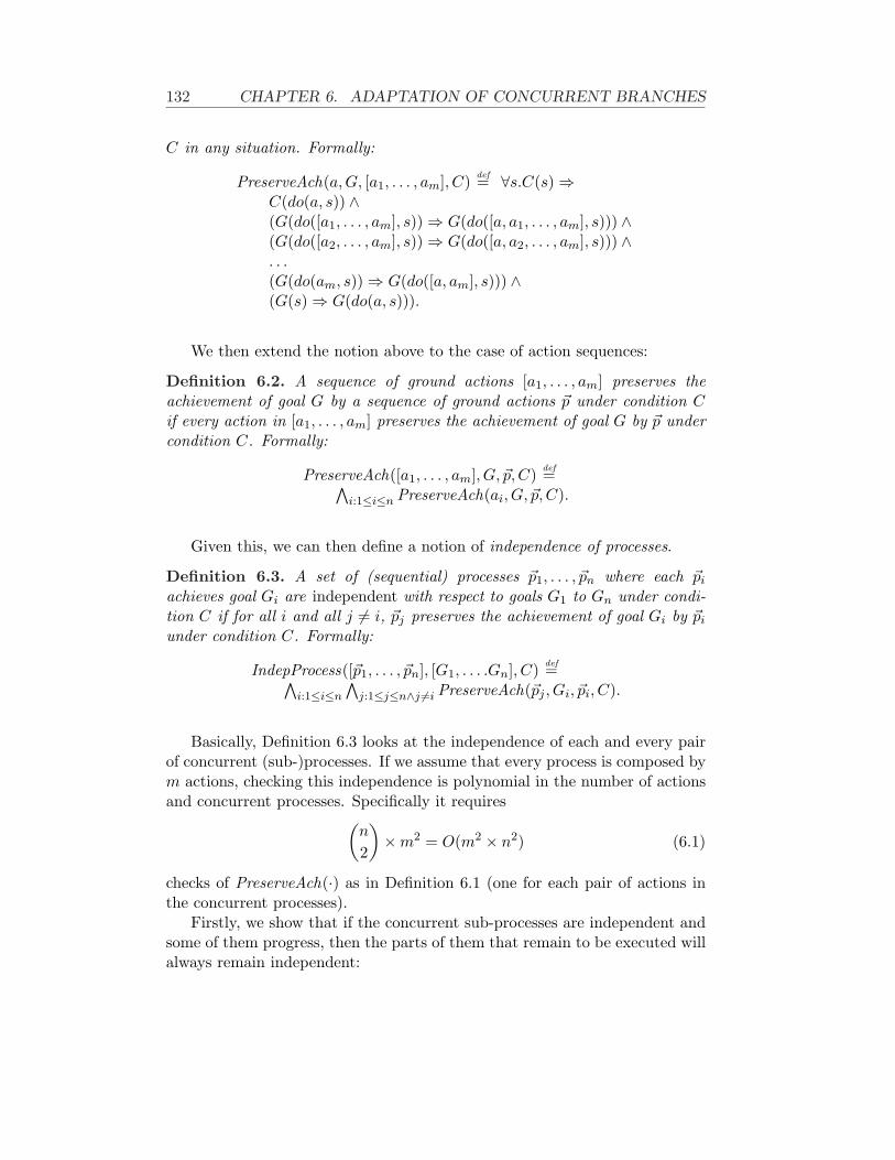
132 CHAPTER 6. ADAPTATION OF CONCURRENT BRANCHES
C in any situation. Formally:
PreserveAch(a,G, [a1, . . . , am], C) def= ∀s.C(s) ⇒C(do(a, s)) ∧(G(do([a1, . . . , am], s)) ⇒ G(do([a, a1, . . . , am], s))) ∧(G(do([a2, . . . , am], s)) ⇒ G(do([a, a2, . . . , am], s))) ∧. . .(G(do(am, s)) ⇒ G(do([a, am], s))) ∧(G(s) ⇒ G(do(a, s))).
We then extend the notion above to the case of action sequences:
Definition 6.2. A sequence of ground actions [a1, . . . , am] preserves theachievement of goal G by a sequence of ground actions ~p under condition Cif every action in [a1, . . . , am] preserves the achievement of goal G by ~p undercondition C. Formally:
PreserveAch([a1, . . . , am], G, ~p, C) def=∧i:1≤i≤n PreserveAch(ai, G, ~p, C).
Given this, we can then define a notion of independence of processes.
Definition 6.3. A set of (sequential) processes ~p1, . . . , ~pn where each ~pi
achieves goal Gi are independent with respect to goals G1 to Gn under condi-tion C if for all i and all j 6= i, ~pj preserves the achievement of goal Gi by ~pi
under condition C. Formally:
IndepProcess([~p1, . . . , ~pn], [G1, . . . .Gn], C) def=∧i:1≤i≤n
∧j:1≤j≤n∧j 6=i PreserveAch(~pj , Gi, ~pi, C).
Basically, Definition 6.3 looks at the independence of each and every pairof concurrent (sub-)processes. If we assume that every process is composed bym actions, checking this independence is polynomial in the number of actionsand concurrent processes. Specifically it requires
(n
2
)×m2 = O(m2 × n2) (6.1)
checks of PreserveAch(·) as in Definition 6.1 (one for each pair of actions inthe concurrent processes).
Firstly, we show that if the concurrent sub-processes are independent andsome of them progress, then the parts of them that remain to be executed willalways remain independent:
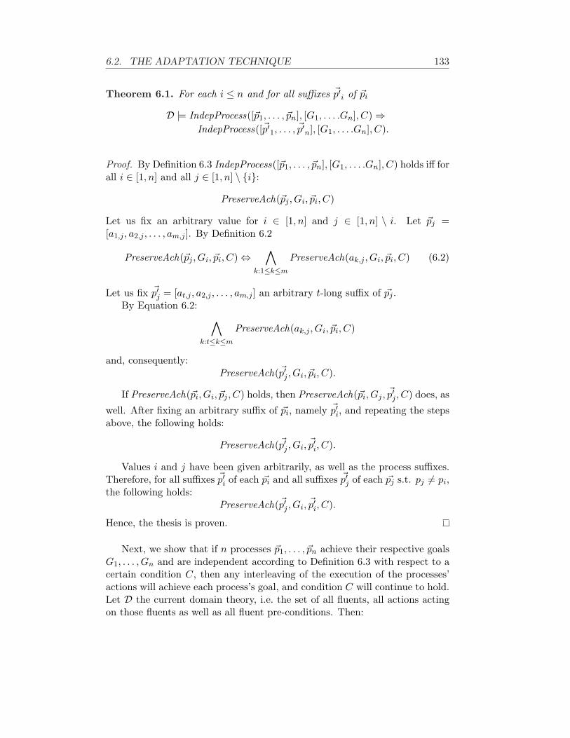
6.2. THE ADAPTATION TECHNIQUE 133
Theorem 6.1. For each i ≤ n and for all suffixes ~p′i of ~pi
D |= IndepProcess([~p1, . . . , ~pn], [G1, . . . .Gn], C) ⇒IndepProcess([~p′1, . . . , ~p′n], [G1, . . . .Gn], C).
Proof. By Definition 6.3 IndepProcess([~p1, . . . , ~pn], [G1, . . . .Gn], C) holds iff forall i ∈ [1, n] and all j ∈ [1, n] \ {i}:
PreserveAch(~pj , Gi, ~pi, C)
Let us fix an arbitrary value for i ∈ [1, n] and j ∈ [1, n] \ i. Let ~pj =[a1,j , a2,j , . . . , am,j ]. By Definition 6.2
PreserveAch(~pj , Gi, ~pi, C) ⇔∧
k:1≤k≤m
PreserveAch(ak,j , Gi, ~pi, C) (6.2)
Let us fix ~p′j = [at,j , a2,j , . . . , am,j ] an arbitrary t-long suffix of ~pj .By Equation 6.2:
∧
k:t≤k≤m
PreserveAch(ak,j , Gi, ~pi, C)
and, consequently:PreserveAch(~p′j , Gi, ~pi, C).
If PreserveAch(~pi, Gi, ~pj , C) holds, then PreserveAch(~pi, Gj , ~p′j , C) does, as
well. After fixing an arbitrary suffix of ~pi, namely ~p′i, and repeating the stepsabove, the following holds:
PreserveAch(~p′j , Gi, ~p′i, C).
Values i and j have been given arbitrarily, as well as the process suffixes.Therefore, for all suffixes ~p′i of each ~pi and all suffixes ~p′j of each ~pj s.t. pj 6= pi,the following holds:
PreserveAch(~p′j , Gi, ~p′i, C).
Hence, the thesis is proven.
Next, we show that if n processes ~p1, . . . , ~pn achieve their respective goalsG1, . . . , Gn and are independent according to Definition 6.3 with respect to acertain condition C, then any interleaving of the execution of the processes’actions will achieve each process’s goal, and condition C will continue to hold.Let D the current domain theory, i.e. the set of all fluents, all actions actingon those fluents as well as all fluent pre-conditions. Then:

134 CHAPTER 6. ADAPTATION OF CONCURRENT BRANCHES
Theorem 6.2.
D |= IndepProcess([~p1, . . . , ~pn], [G1, . . . .Gn], C) ⇒∀s.G1(do([~p1], s)) ∧ . . . ∧Gn(do([~pn], s)) ∧ C(s) ⇒
[∀s′.Do([~p1 ‖ . . . ‖ ~pn], s, s′) ⇒G1(s′) ∧ . . . ∧Gn(s′) ∧ C(s′)].
Proof. By induction on the total length of all processes. Let |pi| be the lengthof process pi, i.e. the number of actions of ~pi. If all processes are emptysequences, then the result trivially follows (base case). Assume the resultholds if the total length of all processes is k. We will show that it must alsohold for k + 1 (induction step).
Assume C(s), G1(do([~p1], s)) ∧ . . . ∧ Gn(do([~pn], s)) andDo([~p1 ‖ . . . ‖ ~pn], s, s′). Processes are such that
∑ni=1 |pi| = k + 1.
Let us assume branch ~pi = [a1,i, a2,i, . . . , am,i] evolves by executing actiona1,i. Let ~p′i = [a2,i, . . . , am,i] be what is left of ~pi after executing a1,i and lets1 = do(a1,i, s).
By applying Theorem 6.1:
IndepProcess([~p1, . . . , ~pn], [G1, . . . .Gn], C) ⇒IndepProcess([~p1, . . . , ~pi−1, ~p′i, ~pi+1, . . . , ~pn], [G1, . . . .Gn], C).
Since IndepProcess([~p1, . . . , ~pn], [G1, . . . .Gn], C), then for all j 6= i
PreserveAch(~pi, Gj , ~pj , C)
and in particularPreserveAch(a1,i, Gj , ~pj , C).
Therefore by Definition 6.1:
G(do([~p1], s1)) ∧ . . . ∧G(do([~pi−1], s1)) ∧G(do([~p′i], s1))∧ G(do([~pi+1], s1)) ∧ . . . ∧G(do([~pn], s1)) ∧ C(s1)
In order to complete the proof, it is now to prove that
IndepProcess([~p1, . . . , ~pi−1, ~p′i, ~pi+1, . . . , ~pn], [G1, . . . .Gn], C)∧G(do([~p1], s1)) ∧ . . . ∧G(do([~pi−1], s1)) ∧G(do([~p′i], s1))∧ G(do([~pi+1], s1)) ∧ . . . ∧G(do([~pn], s1)) ∧ C(s1) ⇒
[∀s′.Do([~p1 ‖ . . . ‖ ~pi−1 ‖ ~p′i ‖ ~pi+1 ‖ . . . ‖ ~pn], s1, s′) ⇒
G1(s′) ∧ . . . ∧Gn(s′) ∧ C(s′)].
And that holds by the induction hypothesis as
|~p1|+ . . . + |~pi−1|+ |~p′i|+ |~pi+1|+ . . . + |~pn| = k.

6.2. THE ADAPTATION TECHNIQUE 135
Next, building on the previous results, we show that such an “independenthandler” ~h can be used for handling a discrepancy ~e breaking a process pi,while allowing all other processes to execute concurrently and achieve theirrespective goals:
Theorem 6.3. Let ~p′i be the process broken by a discrepancy ~e.
D |= ∀s, ~e.IndepProcess([~p′1, . . . , ~p′i−1, [~h; ~p′i], ~p′i+1, . . . ,~p′n],
[G1, . . . , Gi−1, Gi, Gi+1, . . . , Gn], C) ∧G1(do([~p′1], do(~e, s))) ∧ . . . ∧Gi−1(do([~p′i−1], do(~e, s))) ∧Gi+1(do([~p′i+1], do(~e, s))) ∧ . . . ∧Gn(do([~p′n], do(~e, s))) ∧Gi(do([~h, ~p′i], do(~e, s))) ∧ C(do(~e, s)) ⇒
[∀s′.Do([~p′1 ‖ . . . ‖ ~p′i−1 ‖ [~h, ~p′i] ‖ ~p′i+1 ‖ . . . ‖ ~p′n],do(~e, s), s′) ⇒ G1(s′) ∧ . . . ∧Gi−1(s′) ∧Gi(s′)∧Gi+1(s′) ∧ . . . ∧Gn(s′) ∧ C(s′)].
Proof. That derives trivially from applying Theorem 6.2 where:
• ~pidef= [~h, ~p′i];
• pkdef= ~p′k ∀k : 1 ≤ k ≤ n ∧ k 6= i;
• sdef= do(~e, s).
Finally, we show that adding an action sequence ~h for handling a discrep-ancy ~e that breaks a process pi will preserve process independence. Thatholds provided ~h is built as independent of every sub-process different from~pi with respect to condition C. Let R(Gi, do(~pi)) be the situation-suppressedexpression for regression Rs(Gi(do(~pi, s)).
Theorem 6.4. Let ~pi be the process broken by a discrepancy ~e.
D |= IndepProcess([~p1, . . . , ~pi−1, ~pi, ~pi+1, . . . , ~pn],
[G1, . . . , Gi−1, Gi, Gi+1, . . . , Gn], C) ∧∧
j:1≤j≤n∧j 6=i
(PreserveAch(~h,Gj , ~p
′j , C)
∧PreserveAch(~p′j ,Rs(Gi(do(~pi, s)), h, C) ⇒
IndepProcess([~p1, . . . , ~pi−1, [~h; ~pi], ~pi+1, . . . , ~pn],[G1, . . . , Gi−1, Gi, Gi+1, . . . , Gn], C).

136 CHAPTER 6. ADAPTATION OF CONCURRENT BRANCHES
Proof. Let us denote ~h = [h1, . . . , hm] and ~pi = [a1,i, . . . , al,i].Let us fix an arbitrary process ~pj 6= ~pi without loss of generality. By
hypothesis ∧
k:1≤k≤m
PreserveAch(hk, Gj , ~pj , C) (6.3)
as well as ∧
k:1≤k≤l
PreserveAch(ak,i, Gj , ~pj , C) (6.4)
From Equations 6.3 and 6.4, it results by Definition 6.2:
PreserveAch([~h; ~pi], Gj , pj , C) (6.5)
Let se be the situation after the occurrence of a discrepancy ~e. Handler ~h isbuilt such that:
∃s.Rs(Gi(do(~pi, s))
) ∧ do(h, se) = s ∧Gi(do(~pi, s))
In the light of this:
PreserveAch(~pj ,R(Gi(do(~pi))),~h, C) ⇒ PreserveAch(~pj , Gi,~h, C)
Therefore, since by the hypothesis of processes independencePreserveAch(~pj , Gi, ~pi, C), the following holds:
PreserveAch(~pj , Gi, [~h; ~pi], C) (6.6)
Since Equations 6.5 and 6.6 are true for every process pj and by the hy-pothesis of independence of all processes, the thesis holds.
6.2.2 Monitoring-Repairing Technique
On the basis of the results in the previous section, we propose in Figure 6.1an algorithm for adaptation. This algorithm, which is meant to run insidethe PMS, relies on 2 arrays giving information about the status of the nprocesses concurrently running: whether each is completed or not and, in caseof completion, whether successfully or unsuccessfully. Initially every elementof both arrays is set to false.
Routine monitor relies on every process pi sending a message to the PMSwhen it either terminates successfully (message successfullycompleted(i)) oran exception is sensed such that such pi can no longer terminate successfully3
3That is D 2 Rsnow (Gi(do(pi, snow))) where snow is the current situation after sensing adiscrepancy.

6.2. THE ADAPTATION TECHNIQUE 137
completed[]: array of n elementssucceeded[]: array of n elementsinitially()1 for i ← 1 to n2 do completed[i] ← false
3 succeeded[i] ← false
SUB monitor([p1, . . . , pn], [G1, . . . , GN ], C, si)1 if (¬IndepProcess([p1, . . . , pn], [G1, . . . , GN ], C))2 then throw exception3 while (∃i.¬completed[i])4 do m ← waitForMessage()5 if m = successfullyCompleted(i)6 then completed[i] ← true
7 succeeded[i] ← true
8 if m = exception(ie, se)9 then h ← buildHandler(ie, se, [p1, . . . , pn], [G1, . . . , Gn], C)
10 if h = fail
11 then completed[ie] ← true
12 throw exception13 else14 pie ← [h; pie ]15 start(pie )
FUNCTION buildHandler(ie, se, [p1, . . . , pn], [G1, . . . , Gn], C)1 for i ← 1 to n2 do pi ← remains(pi, se)3 h ← planByRegres(R(Gie , do(~pie ))),4 se, [p1, . . . , pn]/pie , [G1, . . . , Gn]/Gie , C)
FUNCTION planByRegres(Goalh, si, [p1, . . . , pn−1], [G1, . . . , Gn−1], C)1 if D |= Goalh(si)2 then return nil
3 else a ← chooseAction(Goalh, si, [p1, . . . , pn−1],4 [G1, . . . , Gn−1], C)5 if a = nil
6 then7 return fail
8 else9 h′ ← planByRegres(Rs(Goalh(do(a, s))),
10 si, [p1, . . . , pn−1], [G1, . . . , Gn−1], C)11 if h = fail
12 then return fail
13 else return [h′; a]
FUNCTION chooseAction(Goalh, si, [p1, . . . , pn−1], [G1, . . . , GN ], C)1 choose an action a s.t. {∃s(¬Goalh(s) ∧Goalh(do(a, s)))}∧2 ∀i.1 ≤ i ≤ (n− 1) ⇒ PreserveAch(a, Gi, pi, C)3 ∧ PreserveAch(pi, Goalh, a, C)4 return a //even nil if there exists no selectable action
Figure 6.1: Pseudo-Code for the adaptation technique.

138 CHAPTER 6. ADAPTATION OF CONCURRENT BRANCHES
(message exception(ie, se) where ie is the “broken” process and se is the result-ing situation after the discrepancy occurrence). We assume that the situationrepresenting the current state in the real word is known and that we have com-plete knowledge of the fluents in that situation. Moreover we assume that inevery situation we can get access to the fluent values in every past situation.4
Finally, we assume, as well, that every process pi is consuming and reducingits size with the execution of tasks. Process pi denotes always the part ofprocess that still needs to be executed: the parts already execute are cut out.
The routine is applicable if all processes are independent of each other.Therefore, before starting its monitoring and repairing, it checks whether theprocess independence assumption holds (lines 1,2). If not, it throws an excep-tion, assuming that in this case an alternative and more intrusive approachwould be used [40].
Later on, in the “monitor and repair” cycle, we listen for arriving messages(line 4). If the message concerns the successful completion of a sub-process,then the arrays are updated accordingly (lines 5-7). Otherwise, the message isabout a sub-process pie that has been broken by a discrepancy. pie is implic-itly halted and we call function buildHandler to search for an adaptationhandler h. If such a handler h is found, it is prefixed to the broken processpie , which becomes (h; pie) (line 14). Finally, the adapted process is startedagain (line 15).
How does the buildHandler function synthesize this handler? Lines 1-2update all processes pi so that they represent the subparts that remain toexecute. Then, the function invokes a regression planner (line 3) [111, 52],which searches for a plan backwards from the goal description. Specifically,the regression planner tries to generate a sequential plan that, starting fromthe current situation se, arrives at some situation sh such that pie can beexecuted again and achieve Gie , i.e. Rsh(Gi(do(pie , sh))).
The regression planning procedure planByRegression recursively andincrementally builds a plan5 checking that every selected action is indepen-dent of each pj (with j 6= ie) with respect to invariant condition C. Indeed,Theorems 6.4 and 6.3 ensure that if the handler only includes actions thatare independent of each pj (with j 6= ie), then, for all possible interleavings,process (h; pie) will achieve its goal Gi and every other process pj with j 6= iewill continue to achieve its goals Gj .
Observe that Theorem 6.1 ensures if processes were originally independentregarding their respective goals and no exceptions are raised, as they evolve,they remain independent.
The technique proposed in this chapter is proved to be sound and complete
4This could be done by logging and storing them in a repository.5Here we assume that plans are returned in form of IndiGolog programs.

6.2. THE ADAPTATION TECHNIQUE 139
if exactly one branch is broken and needs to be recovered.Conversely, if a discrepancy breaks many processes, say k, we assume to
repair them one by one till the k-th, i.e. the i-th is repaired when the first i−1have been already repaired. Of course, this approach is greedy: we repair thei-th without considering the next k − i branches to be recovered; in addition,the sequence of repairing process is arbitrary. For instance, there might bedifferent choices to repair a given i-th branch. Some of them would makeimpossible to repair one the next k − i branch, whereas other choices wouldnot. Since the technique does not take into account the next branches, all ofchoices would be equivalent, and, hence, one might be done such that somebranches are not repairable anymore. Or, even, choosing a certain repairingsequence allows to repair, whereas others do not. That is why the techniqueis only sound for multiple breaks: it could not find a repairing plan, even if itdoes exist.
More formally, let ~e be a discrepancy which breaks k processes, namelyp1, p2, . . . , pk, and let s be the situation before the discrepancy has occurred.Then:
Theorem 6.5 (Soundness). If the algorithm in Figure 6.1 produces han-dlers:~h1 = buildHandler(1, do(~e, s), [~p1, ~p2 . . . , ~pn], [G1, . . . , Gn], C)~h2 = buildHandler(2, do(~e, s), [(~h1; ~p1), ~p2 . . . , ~pn], [G1, . . . , Gn], C). . .~hk = buildHandler(k, do(~e, s), [(~h1; ~p1), (~h2; ~p2), . . . , (~hk−1, ~pk−1), ~pk, . . . , ~pn],
[G1, . . . , Gn], C)
andIndepProcess([~p1, . . . , ~pn], [G1, . . . , Gn], C)∧G1(do(~p1, s)) ∧ . . . ∧Gn(do(~pn, s))
then∀s′.Do([(~h1; ~p1) ‖ . . . ‖ (~hk; ~pk) ‖ ~pk+1 ‖ ~pn],
do(~e, s), s′) ⇒ G1(s′) ∧ . . . ∧Gi−1(s′) ∧Gi(s′)∧Gi+1(s′) ∧ . . . ∧Gn(s′) ∧ C(s′)]
andIndepProcess([(~h1; ~p1), (~h2; ~p2), . . . , (~hk; ~pk),
~pk+1, . . . , ~pn]), [G1, . . . , Gk, Gk+1, . . . , Gn], C).
Proof. The adaptation algorithm will repair firstly process ~p1 since we areassuming that it is enqueued as first. Let h1 be the handler produced byroutine planByRegres to repair it. Handler ~h1 is built such that
∧i:2≤i≤n PreserveAch(~h1, Gi, ~pi)∧PreserveAch(~pi,R(G1, ~p1)),~h1)

140 CHAPTER 6. ADAPTATION OF CONCURRENT BRANCHES
Since for hypothesis there holds IndepProcess([~p1, . . . , ~pn], [G1, . . . , Gn], C), byTheorem 6.4 that follows:
IndepProcess([(~h1; ~p1), ~p2, . . . , ~pn]), [G1, . . . , Gn], C) (6.7)
Let ~h2 be the handler produced by routine planByRegres to repair ~p2.Handler ~h2 is built such that
PreserveAch(~h2, G1, (~h1; ~p1))∧PreserveAch((~h1; ~p1),R(G2, do(~p2)),~h2)∧
i:3≤i≤n PreserveAch(~h2, Gi, ~pi)∧PreserveAch(~pi,R(G2, do(~p2)),~h2)
From Equation 6.7 and by Theorem 6.4, that follows:
IndepProcess([(~h1; ~p1), (~h2; ~p2), . . . , ~pn]), [G1, . . . , Gn], C).
Therefore, after repairing ~pk, we obtain:
IndepProcess([(~h1; ~p1), (~h2; ~p2), . . . , (~hk; ~pk),~pk+1, . . . , ~pn]), [G1, . . . , Gk, Gk+1, . . . , Gn], C).
(6.8)
For all i ∈ [1, k], hi has been built such as do(hi, do(~e, s)) takes to any situations where Rs(G(pi, s)) and, hence, G
(do([~h1; ~p1], do(~e, s))
). From this result and
from Equation 6.8, Theorem 6.2 proves:
∀s′.Do([(~h1; ~p1) ‖ . . . ‖ (~hk; ~pk) ‖ ~pk+1 ‖ ~pn],do(~e, s), s′) ⇒ G1(s′) ∧ . . . ∧Gi−1(s′) ∧Gi(s′)∧Gi+1(s′) ∧ . . . ∧Gn(s′) ∧ C(s′)]
Theorem 6.6 (Completeness). If
∃~h.(∀s′.Do([~p1 ‖ . . . ‖ ~pi−1 ‖ (~h; ~pi) ‖ ~pi+1 ‖ . . . ‖ ~pn],
do(~e, s), s′) ⇒ G1(s′) ∧ . . . ∧Gn(s′) ∧ C(s′))
andIndepProcess([p1, . . . , pi−1(~h; pi), , pi+1, . . . , pn],
[G1, . . . , Gn], C)
then buildHandler returns a repairing handler:
~h = buildHandler(i, do(~e, s), [p1, . . . , pn],[G1, . . . , Gn], C)

6.2. THE ADAPTATION TECHNIQUE 141
such that
∀s′.Do([~p1 ‖ . . . ‖ ~pi−1 ‖ (~h; ~pi) ‖ ~pi+1 ‖ . . . ‖ ~pn],do(~e, s), s′) ⇒ G1(s′) ∧ . . . ∧Gn(s′) ∧ C(s′)
(6.9)
and
indepProcesses([p1, . . . , (h; pi), pn], [G1, . . . , Gi, . . . , Gn], C) (6.10)
Proof. Let us assume ~pi be the process broken by a discrepancy ~e. Let se =do(~e, s) be the resulting situation.
If there exist handlers meeting the requirements of the hypothesis, theinvocation of procedure buildHandler returns one of them, namely ~h:
~h = buildHandler(i, do(~e, s), [p1, . . . , pn],[G1, . . . , Gn], C)
if and only if planByRegress returns ~h:
~h = planByRegres(R(Gi, do(~pi))),se, [p1, . . . , pn]/pi, [G1, . . . , Gn]/Gi, C)
Therefore, we move to prove that if any handler ~h exists such that it achievesany goal Goalh and hypotheses 6.9 and 6.10 hold, then it can be returned byplanByRegres. We prove by induction on the length of ~h.
Let us assume that there may be several plans ~h1, . . . , ~hn. Let fix anarbitrary one, namely ~h, whose length is k:
~h = [h1, . . . , hk]
Let denote Goalh = R(Gi, do(~pi)).If k = 0 (base step), then Goalh already holds, and, hence, planByRe-
gres returns nil (line 2 of the procedure).Otherwise, let us assume by induction hypothesis that the plan
~h′ = [h1, . . . , hk−1], being (k − 1)-long, can be returned by invoking:
~h = planByRegres(Rs(Goalh(do(a, s))),si, [p1, . . . , pn−1], [G1, . . . , Gn−1], C)
In fact, since do(~h′, se) = s and Goalh(do(a, s)) holds, regressionRs(Goalh(do(a, s))) is true in s.

142 CHAPTER 6. ADAPTATION OF CONCURRENT BRANCHES
In order that ~h′ could be the returned handler [h′, a], it is to prove a canbe coinciding with hk. Please note that, given that in situation s = do(~h′, se)regression Rs(Goalh(do(a, s))) holds, the following must also hold:
¬Goalh(s) (6.11)
In addition, since handler ~h is such that Goalh(do(~h, se)) is true, hk has to bethe action turning formula Goalh(·) to true:
Goalh(do(hk, s)) (6.12)
Moreover, since h is one of the handler meeting the hypothesis:
IndepProcess([p1, . . . , pi−1~h, pi+1, . . . , pn], [G1, . . . , Gn], C)
then∀j. (j 6= i) ⇒ PreserveAch(hk, Gj , pj , C)∧
PreserveAch(pj , Goalh, hk, C)(6.13)
Therefore, action hk meets the constraints in Equations 6.11, 6.12 and 6.13,according to which procedure chooseAction picks an action a. In the lightof this, hk is, in fact, an action returnable by such a procedure.
Note that the above procedure becomes easily realizable in practice if thePMS works in a finite domain (e.g., using discretized positions based on actualGPS positions) and propositional logic is sufficient. In fact, one can use anoff-the-shelf regression planner such those mentioned in [111, 52].
6.3 An Example from Emergency Management
In this section, we discuss an example of adaptation in a process concern-ing emergency management. A team is sent to the affected area. Actors areequipped with PDAs which are used to carry on process tasks and communi-cate with each other through a Mobile Ad hoc Network (manet).
A possible process for coping with the aftermath of an earthquake is de-picted in Figure 6.2. Some actors are assessing the area for dangerous partially-collapsed buildings. Meanwhile others are giving first aid to the injured peopleand sending information about required ambulances and filling in a question-naire about the injured people, which are required by the headquarter. Thecorresponding IndiGolog program is depicted in .
In the activity diagram in Figure 6.2, we have labeled every task withthe fluents (in situation-suppressed form) that hold after the successful taskexecution.
6.3. AN EXAMPLE FROM EMERGENCY MANAGEMENT 143
It is worthy noting that, as already told in Section 6.1 all assignments inthe IndiGolog program in Figure 6.3 are made together before the parallelbranches are started. The reason steps from the fact that we are willing tomake all branches independent. Indeed, if the assignments were done insidethe branches themselves, then the assignment made in a branch might bedepending on other assignment made in some parallel branches.
For the sake of simplicity, we detail only those fluents that we are usedlater in the example (see later in this section for the successor state axioms):
proxy(w, y, s) is true if in situation s, service y can work as proxy for servicew. In the starting situation S0 for every pair of services w, y we haveproxy(w, y, S0) = false, denoting that no proxy has yet been chosenfor w.
at(w, p, s) is true if service w is located at coordinate p = 〈px, py, pz〉 insituation s. In the starting situation S0, for each service wi, we haveat(wi, pi, S0) where location pi is obtained through GPS sensors.
infoSent(d, s) is true in situation s if the information concerning injured peo-ple at destination d has been successfully forwarded to the headquarter.For all destinations d infoSent(d, S0) = false.
evaluationOK(s) is true if the photos taken are judged as having a goodquality, with evaluationOK(S0) = false.
assisted(z, s) is true if the injured people in area z have been sup-ported through a first-aid medical assistance. We have that for all zassisted(z, S0) = false.
We assume that the process designers have defined the following goals ofthe three concurrent sub-processes (as required by the framework):
G1(s)def= Q1Compiled(A, s) ∧ EvaluationOK(s)
G2(s)def= assisted(A, s)
G3(s)def= Q2Compiled(A, s) ∧ infoSent(A, s)
In addition, we are using in this example the invariant condition C(s) = truefor all situations s, meaning that we are not using any assumption to showprocess independence.
Before formally specifying the aforementioned fluents, we define some ab-breviations:
available(w, s): which states a service w is available if it is connected to thecoordinator device (denoted by Coord) and is free.

144 CHAPTER 6. ADAPTATION OF CONCURRENT BRANCHES
connected(w, z, s): which is true if in situation s the services w and z areconnected through possibly multi-hop paths.
neigh(w, z, s): which holds if the services w and z are in radio-range in thesituation s.
Their definitions coincide with those given in the example of Chapter 4 and,hence, we do not duplicate them here.
The successor state axioms for the aforementioned fluents are as follows:
at(w, loc, do(t, s)) ⇔(at(w, loc, s) ∧ ∀loc′.t 6= finishedTask(w,Go, loc′)
)∨(¬at(w, loc, s) ∧ t = finishedTask(w,Go, loc) ∧ started(a,Go, loc, s)
)
proxy(w, y, do(x, s)) ⇔ (proxy(w, y, s)∧
∀q.x 6= finishedTask(w, FindProxy, q))
∨(∃w.x = finishedTask(w,FindProxy, ∅)∧∃p.started(w,FindProxy, p, s
) ∧ isClosestAvail(w, y, s))
infoSent(loc, do(t, s)) ⇔ infoSent(loc, s)∨(∃w.t = finishedTask(w, SendToHeadquarter, 〈loc, OK〉)∧at(w, d, s) ∧ ∃y.(proxy(w, y, z) ∧ neigh(w, y, s))∧∃p.started(a, SendToHeadquarter, p, s)
)
evaluationOK(do(t, s)) ⇔ evaluationOK(s)∨(∃w.t = finishedTask(w, Evaluate, OK) ∧ ∃p.started(a,Evaluate, p, s)∧photoTaken(s) ∧ n ≥ threshold
)
assisted(z, do(x, s)) ⇔ assisted(z, s)∨(¬assisted(z, s) ∧ ∃p.started(a, assisted, p, s)∧∃w.x = finishedTask(w, assisted, ∅) ∧ at(w, z, s)
)
In the above, we use the abbreviation isClosestAvail(w, y, s), which holds ify is the geographically closest service to w that is able to act as proxy; if thereis no available proxy in w’s radio range, y = nil:
isClosestAvail(w, y, s) def=(available(y) ∧ at(w, pw, s)∧
at(y, py, s) ∧ provide(y, proxy) ∧ neigh(w, y, s)∧∀z.
(z 6= y ∧ available(z) ∧ provide(z, proxy) ⇒
‖ pz − pw ‖>‖ py − pw ‖))
∨(y = nil ∧ ¬∃z.
(available(z) ∧ provide(z, proxy)
∧neigh(w, z, s)))

6.4. A SUMMARY 145
Automatic Adaptation: an example. To show how our automatic adap-tation technique is meant to work, let us consider an example of discrepancyand a handler plan to cope with it.
Firstly, let us consider the case where the process execution reaches line 6of procedure ReportAssistanceInjured. At this stage, a proxy has beenfound, namely wpr, and the information about injured people is about to besent to the headquarter to request a sufficient number of ambulances to takethem to a hospital. Let s be the current situation. Of course, wpr is selectedto be in radio range of actor w4: neigh(w4, wpr, s).
Let’s assume now that wpr moves away for any reason to a position p′.This corresponds to a discrepancy
~e = [Assign(wpr, Go);Start(wpr, Go, p′);AckTaskCompletion(wpr, Go);Release(wpr, Go); ]
After the internal execution of the discrepancy, the new current situa-tion is se = do(~e, s) where neigh(w4, wpr, se) = false. Therefore, actionfinishedTask(wpr, InformInjured()) does not make infoSent(A) becometrue as it was supposed to.
Since sub-processes EvalTake, AssistInjured and ReportAssistan-ceInjured are independent, the latter, which is affected by the discrepancy,can be repaired without having to stop the other processes.
The goal given to the regression planner isGoalh = photoTaken() ∧ infoSent(A) ∧Q1Compiled(A) in situation-suppressed form. The planner returns possibly the following plan, whichachieves Goalh while preserving independence:
Start(wpr, Go, A);AckTaskCompletion(wpr,Go);Start(w4, InformInjured, A);AckTaskCompletion(w4, InformInjured);
Adaptation can be performed by inserting it after line 5 of procedureReportAssistanceInjured, ensuring that it can achieve its goal withoutinterfering with the other sub-processes.
6.4 A summary
In this chapter we have proposed a sound and complete technique for adaptingsequential processes running concurrently. Such a technique improves, under

146 CHAPTER 6. ADAPTATION OF CONCURRENT BRANCHES
the assumption of independence of the different processes, that proposed inChapter 4, while adopting the same general framework based on planningtechniques in AI.
In the previous approach, whenever a process needs to be adapted, thedifferent concurrently running branches are all interrupted. And a sequenceof actions h = [a1, a2, . . . , an] is placed before them. Therefore, all of thebranches could only resume after the execution of the whole sequence. Theadaption technique proposed here works on identifying whether concurrentbranches are independent (i.e., neither working on the same variables noraffecting some conditions). And, if independent, it can synthesize a recoveryprocess that affects only the branch of interest, without having to block theother branches. Concurrency is a key characteristic of business processes,such that the independence of different branches is likely to yield benefits inpractice.
The proposed technique is made possible by annotating processes in a“declarative” way. We assume that the process designer can annotate action-s/sequences with the goals they are intended to achieve, and on the basis ofsuch declared goals, independence among branches can be verified, and then arecovery process which affects only the branch of interest, without side-effectson the others, is synthesized.

6.4. A SUMMARY 147
Figure 6.2: A possible process to be carried on in disaster managementscenarios

148 CHAPTER 6. ADAPTATION OF CONCURRENT BRANCHES
Main()1 π.w0[available(w0) ∧ ∀c.require(c, QuestBuildings) ⇒ provide(w0, c)];2 Assign(w0, QuestBuildings);3 π.w1[available(w1) ∧ ∀c.require(c, TakePhoto) ⇒ provide(w1, c)];4 Assign(w1, TakePhoto);5 π.w2[available(w2) ∧ ∀c.require(c, EvalPhoto) ⇒ provide(w2, c)];6 Assign(w2, EvalPhoto);7 π.w3[available(w3) ∧ ∀c.require(c, FirstAid) ⇒ provide(w3, c)];8 Assign(w3, FirstAid);9 π.w4[available(w4) ∧ ∀c.require(c, InformInjured) ⇒ provide(w4, c)];
10 Assign(w4, InformInjured);11 π.w5[available(w5) ∧ ∀c.require(c, InjuredQuest) ⇒ provide(w5, c)];12 Assign(w5, InjuredQuest);13 (EvalTake(w0, w1, w2, Loc) ‖ AssistInjured(w3, Loc) ‖14 ReportAssistanceInjured(w4, w5, Loc));15 Release(w0, QuestBuildings);16 Release(w1, TakePhoto);17 Release(w2, EvalPhoto);18 Release(w3, FirstAid);19 Release(w4, InformInjured);20 Release(w5, InjuredQuest);21 Release(w6, SendByGPRS);22 π.w6[available(w6) ∧ ∀c.require(c, SendByGPRS) ⇒ provide(w6, c)];23 Assign(w6, SendByGPRS);24 Start(w6, SendByGPRS, ∅);25 AckTaskCompletion(w6, SendByGPRS);26 Release(w6, SendByGPRS);
EvalTake(w0, w1, w2, Loc)1 Start(w0, QuestBuildings, Loc);2 AckTaskCompletion(w0, QuestBuildings);3 Start(w1, Go, Loc);4 AckTaskCompletion(w1, Go);5 Start(w1, TakePhoto, Loc);6 AckTaskCompletion(w1, TakePhoto);7 Start(w2, Evaluate, Loc);8 AckTaskCompletion(w2, Evaluate);
AssistInjured(w3, Loc)1 Start(w3, Go, Loc);2 AckTaskCompletion(w3, Go);3 Start(w3, FirstAid, Loc);4 AckTaskCompletion(w3, FirstAid);
ReportAssistanceInjured(w4, w5, Loc)1 Start(w4, Go, Loc);2 AckTaskCompletion(w4, Go);3 Start(w4, FindProxy, Loc);4 AckTaskCompletion(w4, FindProxy);5 Start(w4, InformInjured, Loc);6 AckTaskCompletion(w4, InformInjured);7 Start(w5, Go, Loc);8 AckTaskCompletion(w5, Go);9 Start(w5, InjuredQuest, Loc);
10 AckTaskCompletion(w5, InjuredQuest);
Figure 6.3: The IndiGolog program corresponding to the process in Figure 4.2

Chapter 7
Some Covered Related Topics
In the previous chapters we have discussed a technique to deal with the issue ofautomatically adapting process instances when some exogenous events producediscrepancies that make impossible them to be completed. We have described,as well, a concrete implementation and, hence, shown the feasibility of theapproach.
The approach implemented so far can be summarized at high level as inFigure 7.1(a) where the PMS engine of SmartPM is deployed on a certaindevice, usually an ultra mobile laptop (such as Asus Eep PC 1), and, then,other devices exist in which some services, human controlled and/or automatic,are installed.
We envision to move from a centralized approach to a distributed one,where the workflow (i.e., process) execution is not orchestrated by a sole nodebut all devices contribute distributively to carry on the workflow. Indeed, gen-erally speaking, devices may not be powerful enough as well as they mightnot be continuously connected to this central orchestrator. The different localPMSs coordinate through the appropriate exchange of messages, conveyingsynchronization information and the outputs of the performed actions by theservices. The technique described applies successfully the “Roman Model” forService Composition [18] to workflow management. Section 7.1 wants to bea first step towards the conceptualization of decentralized orchestrators. Inthe approach proposed, we do not need the fine granularity to specify explic-itly the PMS actions assign, start, ackTaskCompletion, release. Therefore, wemodel workflow as final-state automata, and the sequence of PMS actions astransactions (i.e., arcs) of the automata. At the same time, the distributedapproach of Section 7.1 aims at trying to find a solution for the challengingissue of synthesizing the schema of a workflow according to the available ser-vices. Typically, like widely demonstrated in WORKPAD as well as many
1http://eeepc.asus.com/
149

150 CHAPTER 7. SOME COVERED RELATED TOPICS
(a) The centralized approach
(b) The distributed approach
Figure 7.1: The centralized vs distributed approach to process management(Some arrows not shown to preserve the figure readability)

7.1. AUTOMATIC WORKFLOW COMPOSITION 151
other research projects 2 , generic workflows for pervasive scenarios are de-signed a-priori and, then, just before a team is dropped off in the operationfield, they need to be customized on the basis of the currently available servicesoffered by the mobile devices of operators actually composing the team.
Both in the centralized and distributed approach, some services are human-based, in the sense that the work performed by services is done by humanswith the support of a so-called work-list handler. So far, we have developedonly a proof-of-concept implementation for the sake of testing the SmartPMfeatures. We aim in the near future at providing SmartPM with full-fledgedwork-list handlers. We envision two two types of work-list handler: a versionfor ultra-mobile PCs and a lighter version for PDAs, “compact” but providingless features. First steps have been already done in these directions.
As far as the PDA version, we have already implemented a version duringthis thesis for the ROME4EU Process Management System, a previous valu-able attempt to deal with unexpected deviations (see [7]). A screen shot of thesystem is also depicted in Figure 5.6(d). We plan to port it to the SmartPMsystem.
As far as the more powerful version for ultra-mobile PCs, Section 7.2 il-lustrates a possible version. It refers to a new visual tool that can aid users inselecting the “right” task among a potentially large number of tasks offered tothem. Indeed, in many scenarios, many different processes need to be carriedon at the same time by the same organisation. Therefore, participants canbe confronted with a great deal of processes and, hence, tasks among whichto pick the next one to work on. Many tools are presenting assigned tasksas a mere list without giving any contextual information helpful for such achoice. At the moment, the tool works in concert with the YAWL ProcessManagement System, but the framework is applicable to any PMS, in general,and to SmartPM, in particular.
7.1 Automatic Workflow Composition
This section proposes a novel technique, sound, complete and terminating,able to automatically synthesize such distributed orchestrators, given (i) thetarget generic workflow to be carried out, in the form of a finite transitionsystem, and (ii) the set of behaviorally-constrained services, again in the formof (non deterministic) finite transition systems. This technique deals with theproblem of synthesizing the distributed orchestrator in presence of serviceswith constrained behaviours.
2cfr. SHARE (http://www.share-project.org), EGERIS (http://www.egeris.org),ORCHESTRA (http://www.eu-orchestra.org), FORMIDABLE(http://www.formidable-project.org)

152 CHAPTER 7. SOME COVERED RELATED TOPICS
This issue has some similarities with the one of automatically synthesizingcomposite services starting from available ones [93, 95, 80, 128, 65, 9]. Inparticular, [9] considers the issue of automatic composition in the case inwhich available services are behaviorally constrained, and [11] in the case inwhich the available services are behaviorally constrained and the results of theinvoked actions cannot be foreseen, but only observable afterwards. All theprevious approaches consider the case in which the synthesized orchestrator iscentralized.
On the other side, the issue of distributed orchestration has been consideredin the context of Web service technologies [8, 94, 25], but with emphasis onthe needed run-time architectures. Our work can exploit such results, even ifthey need to be casted into the mobile scenario (in which service providers areless powerful).
The remaining of the section is as follows. In Section 7.1.1, the generalframework is presented. Section 7.1.2 presents a complete example, in which atarget workflow, possible available services and the automatically synthesizedorchestrators are shown. Section 7.1.3 presents the proposed technique, andfinally Section 7.1.4 presents some discussions and future work.
7.1.1 Conceptual Architecture
As previously introduced, we consider scenarios in which a team consists ofdifferent operators, each one equipped with PDAs or similar hand-held de-vices, running specific applications. The interplay of (i) software functionali-ties running on the device and (ii) human activities to be carried out by thecorresponding operator, are regarded as services, that suitably composed andorchestrated form the workflow that the team need to carry out. Such a work-flow is enacted, during run-time, by the PMS/orchestrator a.k.a. workflowmanagement system).
The service behavior is modeled by the possible sequences of actions. Suchsequences can be nondeterministic; indeed nondeterministic sequences stemnaturally when modeling services in which the result of each action on the stateof the service can not be foreseen. Let us consider as an example, a servicethat allows taking photos of a disaster area; after invoking the operation, theservice can be in a state photo OK (if the overall quality is appropriate), orin a different state photo bad, if the operator has taken a wrong photo, thelight was not optimal, etc. Note that the orchestrator of a nondeterministicservice can invoke the operation but cannot control what is the result of it.In other words, the behavior of the service is partially controllable, and theorchestrator needs to cope with such partial controllability. Note also that ifthe orchestrator observes the status in which the service is after an operation,then it can understand which transition, among those nondeterministically

7.1. AUTOMATIC WORKFLOW COMPOSITION 153
possible in the previous state, has been undertaken by the service. We assumethat the orchestrator can indeed observe states of the available services andtake advantage of this in choosing how to continue in executing the workflow.
The workflow is specified on the basis of a set of available actions (i.e.,those ones potentially available) and a blackboard, i.e., a conceptual sharedmemory in which the services provide information about the output of anaction (cfr. complete observability wrt. the orchestrator). Such a workflow isspecified a-priori (i.e., it encodes predefined procedures to be used by the team,e.g., in emergency management), without knowing which effective services areavailable for its enactment.
The issue is then how to compose (i.e., realize) such a workflow by suitablyorchestrating available services. In the proposed scenario, such a compositionof the workflow is useful when a team leader, before arriving on the operationfield, by observing (i) the available devices and operators constituting theteam (i.e., the available services), and (ii) the target workflow the team is incharge of, need to derive the orchestration.
At run-time (i.e., when the team is effectively on the operation field), theorchestrator coordinates the different services in order to enact the workflow.As a matter of fact, the orchestrator is distributed, i.e., there is not anycoordination device hosting the orchestrator; conversely, each and every devicehosts a local orchestrator, which is in charge of invoking the services residingon its own device. The various local orchestrators have to communicate witheach other in order to make an agreement on the right sequence of services tobe called.
The communications among orchestrators and between the local orches-trator and the services are carried out through an appropriate middleware,which offers broadcasting of messages and a possible realization of the black-board [102]. The blackboard, from an implementation point of view, is alsorealized in a distributed fashion.
7.1.2 A Case Study
Let’s consider a scenario where a disastrous event (e.g., an earthquake) breaksout. The scenario is very similar to those already introduced in other chapters:after giving first assistance to people involved in the affected area, a civilprotection’s team is sent to the spot. Team members, equipped with mobiledevices, need to document damage directly on a situation map so that followingactivities can be scheduled (e.g., reconstruction jobs). Specifically their workis supposed to be focused on three buildings A, B and C. For each buildinga report has to be prepared. Those report should contain: (i) a preliminaryquestionnaire giving a description of the building and (ii) some photos of thebuilding conditions. Filling questionnaires does not require to stay very close

154 CHAPTER 7. SOME COVERED RELATED TOPICS
to buildings, whereas taking photos does.We suppose team to be composed of three mobile services MS1,MS2,MS3,
whose capabilities include compiling questionnaires and taking/evaluatingbuilding pictures, in addition to a repository service RS, which is able to for-ward the documents (questionnaires and pictures) produced by mobile unitsto a remote storage in a central hall. Services can read and write some sharedboolean variables, namely {qA,qB,qC,pA,pB,pC,available}, held in a black-board.
Each service has its own capabilities and limitations, basically dependingon technological, geographical and historical reasons – e.g., a team memberwho, in the past, visited building A, makes its respective unit able to compilequestionnaire A; a unit close to building B can move there, and so on. Mobileservices are described by state-transition diagrams where non-deterministictransitions are allowed. Diagrams of Figures 7.2(a) – 7.2(d) describe, respec-tively, units MS1 – MS3 and RS. An edge outcoming from a state s is labeledby a triple E[C]/A, where both [C] and A are optional, with the following se-mantics: when the service is in state s, if the set of events E occurs andcondition C holds, then: i) change state according to the edge and ii) executeaction A. In this context, a set of events represents a set of requests assignedto the service, which can be satisfied only if the condition (or guard) holds (istrue). Actions correspond to writing messages on the blackboard, while theactual fulfillment of requests is implicitly assumed whenever a state transitiontakes place. In other words, each set of events represents a request for sometasks, which are actually performed, provided the respective condition holds,during the transition. Moreover, blackboard writes can be possibly performed.
For instance, consider Figure 7.2(a). Initially (state S0), MS1 is ableto serve requests: {compile qB} (compile questionnaire about building B),{read pC} (get photo of building C from repository), {move A} (move to, orpossibly around, building A) and {req space} (ask remote storage for freeingsome space). In all such cases, neither conditions nor actions are defined,meaning that, e.g., {move A} simply requires the unit to reach, i.e., actuallymoving to, building A, independently of any condition and without writinganything on the blackboard. After building A is reached (S1), a photo can betaken ({take pA}). A request for this yields a non-deterministic transition,due to the presence of two different outgoing edges labeled with the sameevent and non-mutually-exclusive conditions (indeed, no condition is definedat all). Note that, besides possibly leading to different states (S2 or S3), anon-deterministic transition may, in general, give raise to different blackboardwrites, as it happens, e.g., if a request for {eval pC} is assigned when theservice is in state S5. State S2 is reached when, due to lack of light, thephoto comes out too dark. Then, only photo modification ({modify pA},which makes it lighter) is allowed. On the other hand, state S3 (the photo

7.1. AUTOMATIC WORKFLOW COMPOSITION 155
{ take_pA }
S0S0S5
S3
S4
{ modify_pA, req_space} / { available = T }
{ write_pA } [available] / { pA = T }
{ compile_qB }
{ write_qB } / { qB = T }{ eval_pC } / { pC = F }
{ eval_pC } / { pC = T}
{ read_pC }
{ modify_pA }S1
{ move_A }
S2{ modify_pA }
{ take_pA }
req_space / { available = T }
(a) Mobile Service MS1
{ take_pC }
S0S0
S5
S1
S6
S2
{ move_C }
{ modify_pC, req_space } / {available=T}
{ write_pC } [available] / { pC=T }
{ compile_qB }
{ write_qB } / { qB=T }{ eval_pB } / { pB=F }
{ eval_pB } / { pB=T }
{ read_pB }
S4
{ modify_pC }
S3
{ compile_qC }
{ write_qC } / { qC=T }{ move_C }
(b) Mobile Service MS2
{ take_pB }
S0S0
S3
S1
S4
S2
{ move_B }{ write_pB } [available] / { pB = T }
{ compile_qA }
{ write_qA } / { qA = T }{ eval_pA } / { pA = F }
{ eval_pA } / { pA = T }
{ read_pA }
{ modify_pB }
(c) Mobile Service MS3
S0S0
{ forward } / {available=T}
{ commit } /{pA=pB=pC=qA=qB=qC=F} { forward } / {available=F}
(d) Repository Service RS
Figure 7.2: Mobile services

156 CHAPTER 7. SOME COVERED RELATED TOPICS
{ [¬qA] / compile_qA, [¬qB] / compile_qB,[¬qC] / compile_qC}
S0S0
S3
S1
S4
S2
S5
S6
S8
{ [¬qA] / write_qA, [¬qB] / write_qB,[¬qC] / write_qC,/ forward }
{ [¬pA] / move_A, [¬pB] / move_B,[¬pC] / move_C }
{ [¬pA] / take_pA, [¬pB] / take_pB,[¬pC] / take_pC }
{ [¬pA] / modify_pA,[¬pB] / modify_pB,[¬pC] / modify_pC,[¬available] / req_space }
{ [¬pA] / move_A, [¬pB] / move_B,[¬pC] / move_C }
{ [pA & pB & pC] / commit }
{ [¬pA] / write_pA, [¬pB] / write_pB,[¬pC] / write_pC,/ forward }
{ [¬pA] / eval_pA, [¬pB] / eval_pB,[¬pC] / eval_pC }
S7
{ [¬pA] / read_pA, [¬pB] / read_pB,[¬pC] / read_pC }
Figure 7.3: The target workflow
is quite fine) gives also the possibility to ask the repository for additionalspace while photo modification is being performed ({modify pA,req space}).In such case, {available=T} is written on the blackboard, which announcesthat some space is available in the repository and, thus, additional data canbe stored there. Moreover, state S3 allows for serving a {write pA} request,which has the effect of writing the taken photo into the remote storage. Suchtask can be successfully completed only if there is available space, as requiredby condition [available], and, in such case, it is to be followed by action{pA=T}, in order to announce the availability, in the storage, of a picture ofbuilding A. Now, consider the request for {read pC} outgoing from state S0.Such task gets a photo of building C, if any, from the remote storage, andforces a service transition to state S5. Then, {evaluate pC} can be requestedwith the aim of checking whether or not the photo captures relevant aspectsof building C and consequently accepting or rejecting it. Recall that the photocould be not in the storage. If so, a {pC=F} write is performed. Otherwise,either {pC=T} or {pC=F} can be written on the blackboard, depending onwhether the picture is accepted or not. Finally, we complete the descriptionof the service by observing that task {write qB} can be requested in order towrite a filled questionnaire in the remote storage, assuming it is small enoughto be written without satisfying any additional space condition.
Semantics of other actions, e.g. write qA, is straightforward and, conse-quently, diagrams of units MS2, MS3 and RS can be similarly interpreted.RS is a service representing an interface between mobile units and the com-munication channel used for sending data to remote storage. In facts, task

7.1. AUTOMATIC WORKFLOW COMPOSITION 157
forward must be performed by RS whenever a mobile unit is asked for writ-ing (e.g. write pC or write qB) some data. Forwarding means receiving datafrom mobile services and writing it to remote storage. For security reasons,only mobile services are trusted systems which can ask the storage for freeingspace (req space) and can access the storage for reading (e.g., read pC), whilesending data can be performed only by the repository service.After each forwarding, it may happen that the storage becomes full. Thisis why the forward task is non-deterministic and may yield either a{available=T} or a {available=F} write on the blackboard. On the otherhand, a mobile service performing a {req space} guarantees that remotestorage will free some space, consequently it is deterministic and yields a{available=T} write on the blackboard. Finally, RS is allowed to send theremote storage a commit message, which asks the storage for compressing lastreceived data and consequently makes files no longer available for reading.
The goal of the team is to collect both questionnaires and photos aboutall buildings. In Figure 7.3, a graphical representation of the desired work-flow is shown where, initially: (i) all services are assumed to be in state S0and (ii) blackboard state is {qA=qB=qC=pA=pB=pC=F, available=T}. Edgesoutcoming from each state are labeled by sets of pairs [C]/T , whith the fol-lowing semantics: if, in current state, condition (guard) C holds, then task Tmust be assigned to some service. Hence, each state transition may require,in general, the execution of a set of tasks. Observe that the target workflowis deterministic, that is, no two guards appearing inside different sets whichlabel different edges outcoming from the same state can be true at the sametime.Intuitively, after having filled all questionnaire and taken one photo per build-ing, the target workflow requires services to iterate between states S3-S8 untila a good photo for each building has been sent to the remote storage. Then,the team must be ready to perform the operation again. In order to guaranteethat pictures actually capture relevant aspects of the buildings, a sort of peerreview strategy is adopted, i.e., each photo a unit writes in the remote stor-age must be read, evaluated and approved/rejected by a second unit. Bothapproval and rejection are publicly announced by writing a proper messageon the blackboard (indeed, it is sufficient {pC=F} or {pC=T}). When all doc-uments are sent (questionnaires are not subject to review process) a commitmessage is sent to the remote storage and the team can start a new iteration.
Finally, in Figures 7.4 and 7.5 a solution to the distributed compositionproblem is presented which consists of a set of local orchestrators which, uponexecution, coordinate the services in order to realize the target workflow ofFigure 7.3. Recall that each mobile service is attached to a local orchestratorwhich is able to both assigning tasks to the service itself and broadcasting mes-sages. In order to accomplish their task, that is, realizing workflow transitions

158 CHAPTER 7. SOME COVERED RELATED TOPICS
by properly assigning a subset of workflow requests to the respective services,local orchestrators need to access, for each transition: (i) the set of workflowrequests and (ii) the whole set of messages other orchestrators sent. For thisreason, both workflow requests and orchestrator messages are broadcasted.Each orchestrator transition is labeled by a pair I/O, which means: if, in cur-rent state, I occurs, then perform O, where I = 〈A,M, s〉 and O = 〈A′, M ′〉with the following semantics: A is the set of tasks the workflow requests, M isthe set of (broadcasted) messages the orchestrator received (including its ownmessages), s is the state reached by the attached service after tasks assigned bythe orchestrator (A′, see below) have been performed, A′ ⊆ A is the subset ofactions the local orchestrator assigns to the attached service and M ′ is the setof messages the orchestrator broadcasts after the service performed A′. Nota-tion has been compacted by introducing some shortcuts for set representation.In details, (i) “. . .” stands for “any set of elements”: for instance, in the tran-sition between states S0 and S1 of local orchestrator for MS1 (Figure 7.4(a)),the set {. . . commit} represents any set (of tasks) containing commit; (ii) anelement with the prefix “-” stands for “anything but the element, possiblynothing”: for instance, in the first (from top) transition between states S4 andS5 of Figure 7.4(a), the set {. . . modify pA, -req space} stands for “any set(of tasks) not including req space and including modify pA”.
Observe that local orchestrators are deterministic, that is, at each state,no ambiguity holds on which transition, if any, has to be selected. In general,this is due to the presence of messages, which are useful for selecting whichtasks are to be assigned to each service. As an example, observe that thirdand fourth transitions of Figure 7.4(a) can be performed when a same set oftasks ({. . . req space, modify pA}) is requested by the workflow. The choiceof which one is to be assigned to attached service depends on the messages theorchestrator received, which somehow represent other services current capabil-ities. So, in state S4, when the set of requested tasks includes both req spaceand modify pA: (i) if received messages include m1
3 (that is, the message lo-cal orchestrator for MS1 sends when the service reaches state S3 from S1),then the orchestrator assigns tasks {modify pA, req space} to the service;(ii) otherwise, the set of assigned tasks is {modify pA} and, consequently, therewill be another local orchestrator assigning a set of tasks including req spaceto its respective service, basically depending on the messages it received.
The orchestrators for MS2 and MS3 are roughly similar. The only no-ticeable difference is in transition between state S4 and S5 where the localorchestrator for MS3 assigns the same action modify pB for the attached ser-vice, independently of the other actions to be assigned. Indeed, orchestratorsMS1 and MS2 makes this assignment dependent of the actions which are tobe assigned to other services.

7.1. AUTOMATIC WORKFLOW COMPOSITION 159
< { ... compile_qB }, { … m01 }, S4 > / < { compile_qB }, { m4
1 } >
S0
S3
S1
S4
S2
S5
S6
S8 S7
< { ... write_qB } , { ... m41} , S0 > / < { write_qB}, { m0
1 } >
< { ... move_A }, { ... m01}, S1 >
/ < { move_A }, { m11 } >
< { ... take_pA }, { ... m11 }, S2 >
/ < { take_pA }, { m21 } >
< { ... take_pA } , { ... m11 }, S3 >
/ < { take_pA }, { m31 } >
< {… - req_space modify_pA }, { ... m21 } ∪ { … m3
1 }, S3 > / < { modify_pA }, { m3
1 } >
< { ... req_space }, { ... m01 }, S0 > /
< { req_space }, { m11 } >
< { ... req_space, modify_Pa }, { ... m31 }, S3 > /
< {modify_pA, req_space }, { m31 } >
< { … req_space, modify_pA }, { … m21, m0
2 }, S3 > / < { modify_pA }, { m3
0 } >
< { … req_space, modify_pA }, { … m21, m6
2 }, S3 > / < { modify_pA }, {m3
1 } >
< { …move_A }, { …
m 01 }, S
1 >/ < { move_A }, {
m 11 } >
< { … write_pA }, { … m31 }, S0 >
/ < { write_pA }, { m01 } >
< { … read_pC }, { … m01 }, S5 >
/ < { read_pC }, { m51 } >
< { … eval_pC }, { … m51 },S0 >
/ < { eval_pC }, { m01} >< { … commit }, { … }, { … } > / < { }, { } >
(a) Local orchestrator for MS1
< { ... compile_qC }, { … m02 }, S3 > / < { compile_qC }, { m3
2 } >
S0
S3
S1
S4
S2
S5
S6
S8 S7
< { ... write_qC } , { ... m32} , S4 > / < { write_qC}, { m4
2 } >
< { ... move_C }, { ... m42 }, S5 >
/ < { move_C }, { m52 } >
< { ... take_pC }, { ... m42 }, S6 >
/ < { take_pC }, { m62 } >
< {… - req_space modify_pC }, { ... m62 }, S6 > /
< { modify_pC }, { m62 } >
< { ... req_space, modify_Pa }, { ... m32 }, S6 > /
< {modify_pC }, { m62 } >
< { … req_space, modify_pA }, { … m21, m0
2 }, S6 > / < { req_space }, { m6
2 } >
< { … req_space, modify_pC }, { … m21, m6
2}, S6 > / < {req_space, modify_pC }, {m6
2 } >
< { … write_pC }, { … m62 }, S0 >
/ < { write_pA }, { m02 } >
< { … read_pB }, { … m02 }, S1 >
/ < { read_pC }, { m12 } >
< { … commit }, { … }, { … } > / < { }, { } >
< { ... move_C }, { ..
. m42 }, S5 > / < { move_C }, { m5
2 } >
(b) Local orchestrator for MS2
Figure 7.4: Local orchestrators for services of Figure 7.2 (to be continued)

160 CHAPTER 7. SOME COVERED RELATED TOPICS
< { ... compile_qA }, { … m03 }, S2 > / < { compile_qB }, { m2
3 } >
S0
S3
S1
S4
S2
S5
S6
S8 S7
< { ... write_qA } , { ... m23} , S0 > / < { write_qA }, { m0
3 } >
< { ... move_B }, { ... m03 }, S3 >
/ < { move_B }, { m33 } >
< { ... take_pB }, { ... m33 }, S4 >
/ < { take_pB }, { m43 } >
< { … write_pB }, { … m43 }, S0 >
/ < { write_pB }, { m03 } >
< { … read_pA }, { … m03 }, S1 >
/ < { read_pA }, { m13 } >
< { … eval_pA }, { … m13 }, S0 >
/ < { eval_pA }, { m03} >< { … commit }, { … }, { … } > / < { }, { } >
< { ... move_B }, {
... m03 }, S
3 > / < { m
ove_B }, { m 3
3 } >
< { ... modify_pB }, { ... m43 }, S4 > / < { modify_pB }, { m4
3 } >
(a) Local orchestrator for MS3
S0
S3
S1
S4S2
S5
S6S8 S7
ττττ ≡ < { …} , { … }, { … } > / < { }, { } >
< { … forward } , { … }, S0 > / < { forward }, {m0
4} >
ττττ< { … forward } , { … }, S0 > /
< { forward }, {m04} >
ττττττττ
ττττττττ< { … commit } , { … }, S0 > / < { commit }, {m04} >
< { - commit } , { … }, S0 > / < { }, {m04} >
(b) Local orchestrator for RS
Figure 7.5: Local orchestrators for services of Figure 7.2 (continued) and targetworkflow of Figure 7.3

7.1. AUTOMATIC WORKFLOW COMPOSITION 161
7.1.3 The Proposed Technique
The formal setting. A Workflow Specification Kit (WfSK) K = (A,V)consists of a finite set of actions A and a finite set of variables V, also calledblackboard, that can assume only a finite set of values. Actions have known(but not modeled here) effects on the real world, while they do not changedirectly the blackboard.
Using a WfSK K one can define workflows over K. Formally a workflowW over K is defined as a tuple: W = (S, s0, G, δW , F ), where:
• S is a finite set of workflow states;
• s0 ∈ S is the single initial state;
• G is a set of guards, i.e., formulas whose atoms are equalities (interpretedin the obvious way) involving variables and values.;
• δW ⊆ S×G×2A−{∅}×S is the workflow transition relation: (s, g, A, s′) ∈δW denotes that in the state s, if the guard g is true in the current black-board state, then the set of (concurrent) actions A ⊆ A is executed andthe service changes state to s′; we insist that such a transition relation isactually deterministic: for no two distinct transitions (s, g1, A1, s1) and(s, g2, A2, s2) in δW we have that g1(γ) = g2(γ) = true, where γ is thecurrent blackboard state;
• finally, F ⊆ S is the set of states of the workflow that are final, that is,the states in which the workflow can stop executing.
In other words a workflow is a finite state program whose atomic instructionsare sets of actions of A (more precisely invocation of actions), that brancheson conditions to be evaluated on the current state of the blackboard V.
What characterizes our setting however is that actions in the WfSK donot have a direct implementation, but instead are realized through availableservices. In other words action executions are not independent one from theother but they are constrained by the services that include them. A service isessentially a program for a client (actually the orchestrator, as we have seen).Such a program, however, leaves the selection of the set of actions to performnext to the client itself (actually the orchestrator). More precisely, at eachstep the program presents to the client (orchestrator) a choice of available setsof (concurrent) actions; the client (orchestrator) selects one of such sets; theactions in the selected set are executed concurrently; and so on.
Formally, a service S is a tuple S = (S, s0, G, C, δS , F ) where:
• S is a finite set of states;

162 CHAPTER 7. SOME COVERED RELATED TOPICS
• s0 ∈ S is the single initial state;
• G is a set of guards, as described for workflows;
• C is a set of partial variable assignment for V, that is used to updatethe state of the blackboard;
• δS ⊆ S × G × 2A−{∅} × C × S is the service transition relation, where(s, g, A, c, s′) ∈ δS denotes that in the state s, if the guard g is true inthe current blackboard state and it is requested the execution of the setof actions A ⊆ A, then the blackboard state is updated according to cand the service changes state to s′;
• finally, F ⊆ S is the set of states that can be considered final, that is, thestates in which the service can stop executing, but does not necessarilyhave to.
Observe that, in general, services are nondeterministic in the sense that theymay allow more than one transition with the same set A of actions and com-patible guards evaluating to the same truth value 3. As a result, when theclient (orchestrator) instructs a service to execute a given set of actions, itcannot be certain of which choices it will have later on, since that dependson what transition is actually executed – nondeterministic services are onlypartially controllable.
To each service we associate a local orchestrator. A local orchestrator isa module that can be (externally) attached to a service in order to controlits operation. It has the ability of activating-resuming its controlled serviceby instructing it to execute a set of actions. Also, the orchestrator has theability of broadcasting messages from a given set ofM after observing how theattached service evolved w.r.t. the delegated set of actions, and to access allmessages broadcasted by the other local orchestrators at every step. Noticethat the local orchestrator is not even aware of the existence of the otherservices: all it can do is to access their broadcasted messages. Lastly, theorchestrator has full observability on the blackboard state.
A (messages extended) service history h+S for a given service S =
(S, s0, G,C, δS , F ), starting in a blackboard state γ0, is any finite sequenceof the form (s0, γ0,M0)·A1·(s1, γ1,M1) · · · (s`−1, γ`−1,M `−1)·A` · (s`, γ`,M `),for some ` ≥ 0, such that for all 0 ≤ k ≤ ` and 0 ≤ j ≤ `− 1:
• s0 = s0;
• γ0 = γ0;3Note that this kind of nondeterminism is of a devilish nature – the actual choice is out
of the client (orchestrator) control.

7.1. AUTOMATIC WORKFLOW COMPOSITION 163
• Ak ⊆ A;
• (sj , g, Aj+1, c, sj+1) ∈ δi with g(γj) = true and c(γj) = γj+1 that is,service S can evolve from its current state sj to state sj+1 while updatingthe backboard state from γj to γj+1 according to what specified in c;
• M0 = ∅ and Mk ⊆M, for all k ∈ {0, . . . , `}.The set H+
B denotes the set of all service histories for S.Formally, a local orchestrator O = (P, B) for service S is a pair of functions
of the following form:
P : H+B × 2A → 2A; B : H+
B × 2A × S → 2M.
Function P states what actions A′ ⊆ A to delegate to the attached serviceat local service history h+
B when actions A were requested. Function B stateswhat messages, if any, are to be broadcasted under the same circumstancesand the fact that the attached service has just moved to state s after executingactions A′. We attach one local orchestrator Oi to each available service Si.In general, local orchestrators can have infinite states.
A distributed orchestrator is a set X = (O1, . . . ,On) of local orchestrators,one for each available service Si.
We call device the pair D = (S,O) constituted by a service S and its localorchestrator O.
A workflow mobile environment (WfME) is constituted by a finite set ofdevices E = (D1, . . . ,Dn) defined over the same WfSK K.
Local Orchestrator Synthesis. The problem we are interested in is thefollowing: given n services S1, . . . , Sn over WfSK K = (A,V) and an initialblackboard state γ0, and a workflowW over K, synthesize a distributed orches-trator, i.e., a team of n local orchestrators, such that the workflow is realizedby concurrently running all services under the control of their respective or-chestrators.
More precisely, let S1, . . . ,Sn be the n services, each with Si =(Si, si0, Gi, Ci, δi, Fi), γ0 be the initial state of the blackboard, and W =(SW , sW0, GW , δW , FW) the workflow to be realized.
We start by observing that the workflow (being deterministic) is completelycharacterized by its set of traces, that is, by the set of infinite action sequencesthat are faithful to its transitions, and of finite sequences that in addition leadto a final state. More formally, a trace for W is a sequence of pairs (g, A),where g ∈ G is a guard over V and A ⊆ A is non-empty set of actions, of theform t = (g1, A1) · (g2, A2) · · · such that there exists an execution history 4 for
4Analogous the execution histories defined for services except that they do not includemessages.

164 CHAPTER 7. SOME COVERED RELATED TOPICS
W, (s0, γ0) ·A1 ·(s1, γ1) · · · where gi(γi−1) = true for all i ≥ 1. If the tracet = (g1, A1) · · · (g`, A`) is finite, then there exists a finite execution history(s0, γ0)· · ·(s`, γ`) · · · with s` ∈ FW .
Now, given a trace t = (g1, A1) · (g2, A2) · · · of the workflow W, we saythat a distributed orchestrator X = (O1, . . . ,On) realizes the trace t iff for all` and for all “system history” h` ∈ H`
t,X (formally defined defined below) withg`+1(γ`)= true in the last configuration of h`, we have that Extt,X (h`, A`+1)is nonempty, where Extt,X (h,A) is the set of (|h|+ 1)-length system historiesof the form h · [A1, . . . , An] · (s|h|+1
1 , . . . , s|h|+1n , γ|h|+1,M |h|+1) such that:
• (s|h|1 , . . . , s|h|n , γ|h|,M |h|) is the last configuration in h;
• A =⋃n
i=1 Ai, that is, the requested set of actions A is fulfilled by puttingtogether all the actions executed by every service.
• Pi(h|i, A) = Ai for all i ∈ {1, . . . , n}, that is, the local orchestrator Oi
instructed service Si to execute actions Ai;
• (s|h|i , gi, Ai, ci, s|h|+1i ) ∈ δi with gi(γ|h|) = true, that is, service Si can
evolve from its current state s|h|i to state s
|h|+1i w.r.t. the (current)
variable assignment γ|h|;
• γ|h|+1 ∈ C(γ|h|), where C = {c1, . . . , cn} is the set of the partial variableassignments ci due to each of the service, and C(γ|h|) is the set of black-board states that are obtained from γ|h| by applying each c1, . . . , cn inevery possible order;
• M |h|+1 =⋃n
i=1 Bi(h|i, A, s|h|+1), that is, the set of broadcasted messagesis the union of all messages broadcasted by each local orchestrator.
The set Hkt,X of all histories that implement the first k actions of trace t
and is prescribed by X is defined as follows:
• H0t,X = {(s10, . . . , sn0, γ0, ∅)};
• Hk+1t,X =
⋃hk∈Hk
t,XExtt,X (hk, Ak+1), k ≥ 0;
In addition if a trace is finite and ends after m actions, and all along all itsguards are satisfied, we have that all histories in Hm
t,X end with all services ina final state. Finally, we say that a distributed orchestrator X = (O1, . . . ,On)realizes the workflow W if it realizes all its traces.
In order to understand the above definitions, let us observe that, intu-itively, the team of local orchestrators realizes a trace if, as long as the guardsin the trace are satisfied, they can globally perform all actions prescribed by

7.1. AUTOMATIC WORKFLOW COMPOSITION 165
the trace (each of the local orchestrators instructs its service to do some ofthem). In order to do so, each local orchestrator can use the history of itsservice together with the (global) messages that have been broadcasted so far.In some sense, implicitly through such messages, each local orchestrator getsinformation on the other service local histories in order to take the right deci-sion. Furthermore, at each step, each local orchestrator broadcasts messages.Such messages will be used in the next step by all service orchestrators tochoose how to proceed.
Our technical results make use of some outcomes given in [122], which canbe summarised by the following theorem.
Theorem 7.1. There exists a sound, complete and terminating procedure forcomputing a distributed orchestrator X = (O1, . . . ,On) that realizes a workflowW over a WfSK K relative to services S1, . . . ,Sn over K and blackboard stateγ0. Moreover each local orchestrator Oi returned by such a procedure is finitestate and require a finite number of messages (more precisely message types).
Observe that there exists no finiteness limitation on the number of statesof the local orchestrators, nor on the number of messages to be exchanged.Therefore, it does not lose generality.
The synthesis procedure is based on the general techniques proposed in[10, 11, 32], based on a reduction of the problem to satisfiability of a Propo-sitional Dynamic Logic formula [61] whose models roughly correspond to or-chestrators.5 From a realization point of view, such a procedure can be imple-mented through the same basic algorithms behind the success of the descrip-tion logics-based reasoning systems used for OWL6, such as FaCT7, Racer8,Pellet9, and hence its applicability appears to be quite promising. The readershould note that the technique is not exploited at run-time, but before the exe-cution of the services and the local orchestrators effectively happens, thereforethe requirements of mobile scenarios are not violated (e.g., just to have a con-crete example, it can be run on a laptop on the jeep taking the team on theoperation field).
7.1.4 Final remarks
This section has studied the workflow composition problem within a dis-tributed general setting; the solutions proposed here are therefore palatable toa wide range of contexts, e.g., nomadic teams in emergency management, in
5There are also works that study alternatives based on model checking techniques.6http://www.omg.org/uml/7http://www.cs.man.ac.uk/ horrocks/FaCT/8http://www.sts.tu-harburg.de/ r.f.moeller/racer/9http://www.mindswap.org/2003/pellet/

166 CHAPTER 7. SOME COVERED RELATED TOPICS
which we have multiple independent agents and a centralized solution is notconceivable.
We plan to implement concretely this approach in the context of the re-search project WORKPAD, widely introduced in Section 2, as well as in an-other project SM4All [21]. SM4All is investigating an innovative platform forcollaborating smart embedded services in pervasive and person-centric envi-ronments, through the use of semantic techniques and workflow composition.
In conclusion, the kind of problems we dealt with are special forms of reac-tive process synthesis [109, 110]. It is well known that, in general, distributedsolutions are much harder to get than centralized ones [110, 78]. This hasnot hampered our approach since we allow for equipping local controllers withautonomous message exchange capabilities, even if such capabilities are notpresent in the services that they control.
7.2 Visual Support for Work Assignment in ProcessManagement Systems
This section describes a novel work-list handler that is able to support processparticipants when choosing the next work item to work on. The work listhandler component takes care of work distribution and authorisation issuesby assigning work items to appropriate participants. Typically, it uses a so-called “pull mechanism”, i.e., work is offered to all resources that qualify andthe first resource to select the work item will be the only one executing it. Toallow users to “pull the right work items in the right order”, basic informationis provided, e.g., task name, due date, etc. However, given the fact that thework list is the main interface of the PMS with its users it seems importantto provide support that goes beyond a sorted list of items. If work itemsare selected by less qualified users than necessary or if users select items in anon-optimal order, then the performance of the overall process is hampered.
Assume the situation where multiple resources have overlapping roles andauthorisations and that there are times where work is piling up (i.e., anynormal business). In such a situation the questions listed below are relevant.
• “What is the most urgent work item I can perform?”
• “What work item is, geographically speaking, closest to me?”
• “Is there another resource that can perform this work item that is closerto it than me?”
• “Is it critical that I handle this work item or are there others that canalso do this?”

7.2. VISUAL SUPPORT FOR WORK ASSIGNMENT IN PMS 167
• “How are the work items divided over the different departments?”
To our knowledge, commercial as well as open source PMSs present worklists simply as a list of work items each with a short textual description.Some products sort the work items in a work list using a certain priorityscheme specified at design time and not updated at run time. To supportthe user in a better way and assist her in answering the above questions, weuse diagrams. A diagram can be a geographical diagram (e.g., the map of auniversity’s campus). But other diagrams can be used, e.g., process schemas,organisational diagrams, Gantt charts, etc. Work items can be visualised bydots on diagrams. By not fixing the type of diagram, but allowing this choiceto be configurable, different types of relationships can be shown thus providinga deeper insight into the context of the work to be performed.
Work items are shown on diagrams. Moreover, for some diagrams alsoresources can be shown, e.g., the geographical position of a user. Besidesthe “diagram metaphor” we also use the “distance metaphor”. Seen fromthe viewpoint of the user some work items are close while others are fartheraway. This distance may be geographic, e.g., a field service engineer maybe far away from a malfunctioning printer at the other side of the campus.However, many other distance metrics are possible. For example, one cansupport metrics capturing familiarity with certain types of work, levels ofurgency, and organisational distance. It should be noted that the choice ofmetric is orthogonal to the choice of diagram thus providing a high degree offlexibility in context visualisation. Resources could for example opt to see ageographical map where work items, whose position is calculated based on afunction supplied at design time, display their level of urgency.
This section proposes different types of diagrams and distance metrics.Moreover, the framework has been implemented and integrated in YAWL.10
YAWL is an open source workflow system based on the so-called workflowpatterns. However, the framework and its implementation are set-up in sucha way that it can easily be combined with other PMSs.
The section is structured as follows. Section 7.2.1 discusses the state ofthe art in work list visualisation in PMSs, whereas Section 7.2.2 provides adetailed overview of the general framework. Section 7.2.5 focusses on the im-plementation of the framework and highlights some design choices in relationto user and system interfaces. In Section 7.2.9 the framework is illustratedthrough a case study. Section 7.2.10 summarises the contributions and out-lines avenues of future work aimed at improving the operationalisation of theframework.
10www.yawlfoundation.org

168 CHAPTER 7. SOME COVERED RELATED TOPICS
7.2.1 Related Work
Little work has been conducted in the field of work list visualisation. Visualisa-tion techniques in the area of PMS have predominantly been used to aid in theunderstanding of process schemas and their run time behaviour, e.g. throughsimulation [60] or process mining [135]. Although the value of business processvisualisation is acknowledged, both in the literature [15, 86, 124, 145] and inthe industry, little work has been done in the context of visualising work items.
The aforementioned body of work does not provide specific support forcontext-dependent work item selection. This is addressed though in the workby Brown and Paik [17], whose basic idea is close to the proposal here. Imagescan be defined as diagrams and mappings can be specified between work itemsand these diagrams. Work items are visualized through the use of intuitiveicons and the colour of work items changes according to their state. However,the approach chosen does not work so well in real-life scenarios where manywork items may have the same position (especially in course-grained diagrams)as icons with the same position are placed alongside each other. This may leadto a situation where a diagram is completely obscured by its work items. Inour approach, these items are coalesced in a single dot of which the size isproportionate to their number. By gradually zooming in on such a dot, theindividual work items cam become visible again. In addition, in [17] thereis no concept similar to our distance notion, which is an ingredient that canprovide significant assistance with work item selection to resources. Finally,the work of Brown and Paik does not take the visualisation of the positions ofresources into account.
Also related is the work presented in [77], where proximity of work itemsis considered without discussing their visualization.
Most PMSs present work lists as a simple enumeration of their work items,their textual descriptions, and possibly information about their priority and/ortheir deadlines. This holds both for open source products, as e.g. jBPM11 andTogether Workflow12, as for commercial systems, such as SAP Netweaver13 andFlower14. An exception is TIBCO’s iProcess Suite15 which provides a richertype of work list handler that partially addresses the problem of supportingresources with work item selection. Figure 7.6 depicts a screen shot of thework list handler. In the bottom left corner a resource’s work list is shown,and above this the lengths of the work lists of other resources is shown. Byclicking on a work item, a resource can see it on a Google Map positioned
11jBPM web site - http://www.jboss.com/products/jbpm12Together Workflow web site - http://www.together.at/together/prod/tws/13Netweaver web site - http://www.sap.com/usa/platform/netweaver14Flower web site - http://global.pallas-athena.com/products/bpmflower product/15iProcess Suite web site - http://www.tibco.com/software/business process management/

7.2. VISUAL SUPPORT FOR WORK ASSIGNMENT IN PMS 169
Figure 7.6: TIBCO’s iProcess Client
where it should be executed. The iProcess Suite also supports a kind of look-head in the form of a list of “predicted” work items and their start times.One can also learn about projected deadline expirations and exception flows.This is achieved through the use of expected durations specified at designtime for the various tasks. Our visualisation framework is more accurate as itcan take actual execution times of work items of a task into account throughthe use of log files when considering predictions for new work items of thattask. Basically, the iProcess Suite provides support for some specific views(geographical position, deadline expiration) but these are isolated from eachother. Our approach allows these views (and others) to be combined (e.g. ageographical view where deadlines are also visualised) thus enabling the use ofviews that may prove useful in certain contexts. Our approach also generalisesover the type of diagram and goes beyond support for a single diagram as inthe iProcess Suite (a geographical map).
7.2.2 The General Framework
The proposed visualisation framework is based on a two-layer approach: (1)diagrams and (2) the visualisation of work items based on a distance notion.A work item is represented as a dot positioned along certain coordinates on abackground diagram. A diagram is meant to capture a particular perspectiveof the context of the process. Since a work item can be associated with severalperspectives, it can be visualised in several diagrams (at different positions).Diagrams can be designed as needed. When the use of a certain diagram

170 CHAPTER 7. SOME COVERED RELATED TOPICS
Process context view Possible diagram and mappingThe physical environmentwhere tasks are going to beperformed.
A real geographical diagram (e.g., Google map). Work items are placedwhere they should be performed and resource are placed where theyare located.
The process schema of thecase that work items belongto.
The process schema is the diagram and work items are placed on topof tasks that they are an instance of.
Deadline expiration of workitems.
The diagram is a time-line where the origin is the current time. Workitems are placed on the time-line at the latest moment when they canstart without their deadline expiring.
The organisation that is incharge of carrying out the pro-cess.
The diagram is an organizational chart. Work items are associatedwith the role required for their execution. Resources are also shownbased on their organizational position.
The materials that are neededfor carrying out work items.
The diagram is a multidimensional graph where the axes are the ma-terials that are needed for work item execution. Let us assume thatmaterials A and B are associated with axes x and y respectively. Inthis case, a work item is placed on coordinates (x, y) if it needs aquantity of x of material A and a quantity y of material B.
Costs versus benefits in exe-cuting work items.
In this case, the axes represent “Revenue” (the amount of money re-ceived for the performance of work items) and “Cost” (the expense oftheir execution). A work item is placed on coordinates (x, y) if therevenue of its execution is x and its cost is y. In this case one is bestoff executing work items close to the x axis and far from the origin.
Table 7.1: Examples of diagrams and mappings.
is envisaged, the relationship between work items and their position on thediagram should be specified through a function determined at design time.Table 7.1 gives some examples of context views and the corresponding workitem mapping.
Several active “views” can be supported whereby users can switch fromone view to another. Resources can (optionally) see their own position on thediagram and work items are coloured according to the value of the applicabledistance metric. Additionally, it may be helpful to show executing work itemsas well as the position of other resources. Naturally, these visualisations aregoverned by the authorisations that are in place.
Our framework assumes a generic lifecycle model as described in [120],which is slightly more elaborated than the SmartPM one. First, a work itemis created indicating that it is ready for distribution. The item is then offeredto appropriate resources. A resource can commit to the execution of the item,after which it moves to the allocated state. The start of its execution leads itto the next state, started, after which it can successfully complete, it can besuspended (and subsequently resumed) or it can fail altogether. During run-time a workflow engine (in our case the YAWL engine) informs the frameworkabout the lifecyle states of work items.

7.2. VISUAL SUPPORT FOR WORK ASSIGNMENT IN PMS 171
7.2.3 Fundamentals
In this section the various notions used in our framework, e.g. work item andresource, are defined formally.
Definition 7.1 (Work item). A work item w is a tuple (c, t, i, y, e, l),where:
• c is the identifier of the case that w belongs to.
• t is the identifier of the task of which w is an instance.
• i is a unique instance number.
• y is the timestamp capturing when w moved to the “offered” state.
• e is the (optional) deadline of w.
• l represents the (optional) GPS coordinates where w should be executed.
Dimensions y and l may be undefined in case the work item w is notyet offered or no specific execution location exists respectively. The e valueconcerns timers which may be defined in YAWL processes. A process regionmay be associated with a timer. When the timer expires, the work items partof the region are cancelled. Note that a work item can potentially be a partof more than one cancellation region and that this has implications for thedefinition of y. In such a case the latest possible completion time with respectto these cancellation regions is assumed.
Definition 7.2 (Resource). A resource r is a pair (j, l), where:
• j is the identifier of the resource.
• l represents the (optional) GPS coordinates where the resource is cur-rently located.
The notation wx is used to denote the projection on dimension x of workitem w, while the notation ry is used to denote the projection on dimensiony of resource r. For example, wt yields the task of which work item w is aninstance.
Work items w′ and w′′ are considered to be siblings iff w′t = w′′t . The setCoordinates consists of all possible coordinates. Elements of this set will beused to identify various positions on a given map.
Definition 7.3 (Position function). Let W and R be the set of work itemsand resources. Let M be the set of available maps. For each available mapm ∈ M , there exists a function positionm : W ∪ R 6→ Coordinates whichreturns the current coordinates for work items and available resources on mapm.
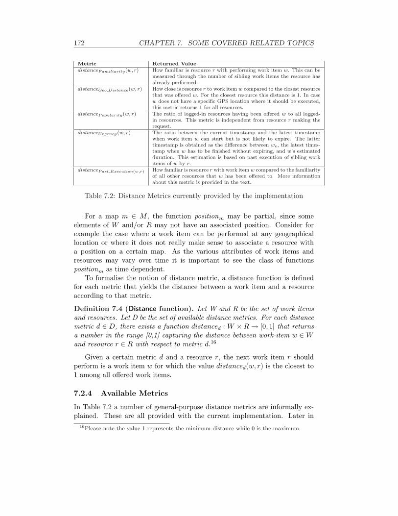
172 CHAPTER 7. SOME COVERED RELATED TOPICS
Metric Returned ValuedistanceFamiliarity(w, r) How familiar is resource r with performing work item w. This can be
measured through the number of sibling work items the resource hasalready performed.
distanceGeo Distance(w, r) How close is resource r to work item w compared to the closest resourcethat was offered w. For the closest resource this distance is 1. In casew does not have a specific GPS location where it should be executed,this metric returns 1 for all resources.
distancePopularity(w, r) The ratio of logged-in resources having been offered w to all logged-in resources. This metric is independent from resource r making therequest.
distanceUrgency(w, r) The ratio between the current timestamp and the latest timestampwhen work item w can start but is not likely to expire. The lattertimestamp is obtained as the difference between we, the latest times-tamp when w has to be finished without expiring, and w’s estimatedduration. This estimation is based on past execution of sibling workitems of w by r.
distancePast Execution(w,r) How familiar is resource r with work item w compared to the familiarityof all other resources that w has been offered to. More informationabout this metric is provided in the text.
Table 7.2: Distance Metrics currently provided by the implementation
For a map m ∈ M , the function positionm may be partial, since someelements of W and/or R may not have an associated position. Consider forexample the case where a work item can be performed at any geographicallocation or where it does not really make sense to associate a resource witha position on a certain map. As the various attributes of work items andresources may vary over time it is important to see the class of functionspositionm as time dependent.
To formalise the notion of distance metric, a distance function is definedfor each metric that yields the distance between a work item and a resourceaccording to that metric.
Definition 7.4 (Distance function). Let W and R be the set of work itemsand resources. Let D be the set of available distance metrics. For each distancemetric d ∈ D, there exists a function distanced : W × R → [0, 1] that returnsa number in the range [0,1] capturing the distance between work-item w ∈ Wand resource r ∈ R with respect to metric d.16
Given a certain metric d and a resource r, the next work item r shouldperform is a work item w for which the value distanced(w, r) is the closest to1 among all offered work items.
7.2.4 Available Metrics
In Table 7.2 a number of general-purpose distance metrics are informally ex-plained. These are all provided with the current implementation. Later in
16Please note the value 1 represents the minimum distance while 0 is the maximum.

7.2. VISUAL SUPPORT FOR WORK ASSIGNMENT IN PMS 173
this section, we formalise the notion of metrics. Let us denote R as the setof resources currently logged in. In order to make explanations easier, someauxiliary functions are introduced.
past execution(w,r) yields the weighted mean of the past execution times ofthe last h-th work items performed by r among all work item siblings ofw. In this context, the past execution time of work item w′ is defined asthe duration that elapsed between its assignment to r and its successfulcompletion. Let timei(w, r) be the execution time of the i-th last workitem among w’s siblings performed by r, then:
past execution(w, r) =
j(w,r,h)∑
i=1
αi−1 · timei(w, r)
j(w,r,h)∑
i=1
αi−1
(7.1)
where constant α ∈ [0, 1] and value j(w,r,h) is the minimum between agiven constant h and the number of sibling work items of w performedby r. Both h and α have to be tuned through testing. If value j(w,r,h) isequal to zero, past execution(w, r) is assumed to take an arbitrary largenumber.17 The intuition behind this definition stems from the fact thatmore recent executions should be given more consideration and henceweighted more as they better reflect resources gaining experience in theexecution of instances of a certain task.
Res(w) returns all currently logged-in resources that have been offered w:
Res(w) = {r ∈ R | w is offered to r}.
best past execution(w) denotes the smallest value for past execution(w, r)computed among all logged-in resources r qualified for w. Specifically:
best past execution(w) = minr′∈Res(w)
past execution(w, r′)
bestDistance(w) returns the minimum geographic distance between a givenwork-item w and all qualified resources:
best Distance(w) = minr′∈Res(w)
‖wl − r′l‖
where ‖wl − r′l‖ stands for the Euclidian distance between the GPS co-ordinates where w should be executed and the GPS location of resourcer. Function best Distance(w) is not total since wl may be undefined forcertain work items w.
17Technically, we set it as the maximum floating value.

174 CHAPTER 7. SOME COVERED RELATED TOPICS
Using these auxiliary functions the following metrics can be defined:
1. Familiarity. How familiar is resource r with performing work item w.This can be measured through the number of sibling work items the resourcehas already performed:
distanceFamiliarity(w, r) ={
0 best past execution(w) →∞best past execution(w)
past execution(w,r) otherwise
The best past execution(w) value can tend to infinite, if nobody has ever ex-ecuted work items for task wt. Otherwise, if someone executed work itemsiblings of wt but r did not, then past execution(w, r) →∞ and, hence,distanceFamiliarity(w, r) → 0.
2. Popularity. The ratio of logged-in resources having been offered w toall logged-in resources. This metric is independent from resource r makingthe request. The intuition is that if many resources can perform w then it isquite distant from every resource. Indeed, even if a resource doesn’t pick wfor performance, it is likely someone else may execute w. Therefore:
distancePopularity(w, r) = 1− |Res(w)||R|
If every resource can perform w, then the distance is 0. If many resources canperform w, then the value is near to 1.
3. Urgency. The ratio between the current timestamp and the latest times-tamp when work item w can start but is not likely to expire. This secondtimestamp is obtained from we, the latest timestamp when w has to be fin-ished without expiring, and w’s estimated duration. This estimation relies onthe past execution by r of w’s sibling work items. Specifically:
distanceUrgency(w, r) ={
1− tnowwe−pastExecution(w,r) we is defined
0 we is undefined
where tnow stands for the current timestamp. If r has never performedwork-items for the same task wt, pastExecution(w, r) → ∞ and, hence,distanceUrgency(w, r) → 0.
4. Relative Geographic Distance. How close is resource r to work itemw compared to the closest resource that was offered w. For the closest resource

7.2. VISUAL SUPPORT FOR WORK ASSIGNMENT IN PMS 175
this distance is 1. In case w does not have a specific GPS location where itshould be executed, this metric returns 1 for all resources. Its definition is:
distanceRelative Geo(w, r) =
1− ‖wl−rl‖bestDistance(w) bestDistancet(w) > 0
0 bestDistancet(w) = 01 bestDistancet(w) is undef
5. Relative Past Execution. The metric chosen combines the familiarityof a resource with a certain work item and the familiarity of other resourcesthat are able to execute that work item:
distanceRelative Past Execution(w, r) =1/past execution(w, r)∑
r′∈Res(w)
1/past execution(w, r′)
.
(7.2)Let us give an informal explanation. First observe that if exactly one resourcer exists capable of performing work item w, then the equation yields one.If n resources are available and they roughly have the same familiarity withperforming work item w, then for each of them the distance will be about1/n. It is clear then that as n increases in value, the value of the distancemetric approaches zero. If on the other hand many resources exist that aresignificantly more effective in performing w than a certain resource r, then thevalue of the denominator increases even more and the value of the metric forw and r will be closer to zero.
For instance, let us suppose that at time t there are n resources capableof performing w. Let us assume that, on average, one of them, namely r1 issuch that past execution(w, r1) = d. Moreover, let us also assume that theother resources required twice this amount of time on average in the past, i.e.for each resource ri (with i > 1) past execution(w, ri) = 2d.
In such a situation, the distance metric value for r1 is as follows:
distance(w, r1,Relative Past Execution) =
=1
past execution(w,r1)
1past execution(w,r1) +
∑ni=2
1past execution(w,ri)
=1d
1d
+∑n
i=212d
=1
1 + n−12
=2
1 + n
This value is greater than 1/n, if n > 1 (i.e., there are al least two resourcesthat may perform w). If n = 1, then it is easy to see that the obtained valueis 1 for both.

176 CHAPTER 7. SOME COVERED RELATED TOPICS
Conversely, the value for any other resource ri (with i > 1) is as follows:
distance(w, ri,Relative Past Execution) =
=1
past execution(w,ri)
1past execution(w,r1) +
∑ni=2
1past execution(w,ri)
=12d
1d
+∑n
i=212d
=1/2
1 + n−12
=1
1 + n
For all n > 0, this value is smaller than 2n+1 , that is the metric value for r1.
Work-item ageing. Some of the metrics above suffer from the fact thattheir values do not change over time. Therefore, if some work-items have asmall value with respect to those metrics, it is likely that there are alwaysother work items that have a greater value for those metrics. If resourcesbehave “fairly”, picking always work items that provide more benefit for theorganizations, some work-items could remain on a work list for a very longtime or even indefinitely.
Therefore, we devised a technique of ageing work-items that occur on worklists in such a way that they eventually become the least distant work item.Let d be any metric and χten = distanced(w, r) be the distance value whenw becomes enabled, where w, r are, respectively, a metric and resource. Thedistance value with respect to metric d at time ten + t ages as follows:
χten+t = 1− (1− χten) · exp−α·t (7.3)
If t = 0, then χten+t = χten and if t →∞ (i.e., time t increases indefinitely),then χten+t → 1. Please note that if α = 0, then work-items do not age. Thegreater value α, the more quickly Equation 7.3 approaches 1 when t increases.Vice versa, smaller values of α make the growth of Equation 7.3 with t slower.
7.2.5 Implementation
The general framework described in the previous section has been opera-tionalised through the development of a component that can be plugged intothe YAWL system. Section 7.2.6 gives an overview of YAWL18, an opensource PMS developed by the Queensland University of Technology, Brisbane(Australia), in cooperation with the Technical University of Eindhoven, TheNetherlands.
18http://www.yawlfoundation.org

7.2. VISUAL SUPPORT FOR WORK ASSIGNMENT IN PMS 177
Section 7.2.7 illustrates some of the visualisation features provided by theimplementation, whereas Section 7.2.8 focusses on how the component fitswithin the YAWL architecture.
7.2.6 The YAWL system
The YAWL environment is an open source PMS, based on the workflow pat-terns [120, 134], using a service-oriented architecture. The YAWL engine andall other services (work list handler, web-service broker, exception handler,etc.) communicate through XML messages.
YAWL offers the following distinctive features:
• YAWL offers comprehensive support for the control-flow patterns. It isthe most powerful process specification language for capturing control-flow dependencies.
• The data perspective in YAWL is captured through the use of XMLSchema, XPath and XQuery.
• YAWL offers comprehensive support for the resource patterns. It is themost powerful process specification language for capturing resourcingrequirements.
• YAWL has a proper formal foundation. This makes its specificationsunambiguous and automated verification becomes possible (YAWL offerstwo distinct approaches to verification, one based on Reset nets, theother based on transition invariants through the WofYAWL editor plug-in).
• YAWL has been developed independent from any commercial interests.It simply aims to be the most powerful language for process specification.
• For its expressiveness, YAWL needs few constructs compared with otherlanguages, such as BPMN.
• YAWL offers unique support for exceptional handling, both those thatwere and those that were not anticipated at design time.
• YAWL offers unique support for dynamic workflow through theWorklets-approach. Workflows can thus evolve over time to meet newand changing requirements.
• YAWL aims to be straightforward to deploy. It offers a number of auto-matic installers and an intuitive graphical design environment.

178 CHAPTER 7. SOME COVERED RELATED TOPICS
• Through the BPMN2YAWL component, BPMN models can be mappedto the YAWL environment for execution.
• The Declare component (released throgh declare.sf.net) provides uniquesupport for specifying workflows in terms of constraints. This approachcan be combined with the Worklet approach thus providing very poewr-ful flexibility support.
• YAWL’s architecture is Service-oriented and hence one can replace ex-isting components with one’s own or extend the environment with newlydeveloped components.
• The YAWL environments supports the automated generation of forms.This is particularly useful for rapid prototyping purposes.
• Automated tasks in YAWL can be mapped to Web Services or to Javaprograms.
• Through the C-YAWL approach a theory has been developed for theconfiguration of YAWL models.19.
• Simulation support is offered through a link with the ProM environ-ment.20 Through this environment it is also possible to conduct post-execution analysis of YAWL processes (e.g. in order to identify bottle-necks).
The YAWL work-list handler is developed as a web application. Its graph-ical interface uses different tabs to show the various queues (e.g., started workitems) (see Figure 7.7). The visualisation framework can be accessed througha newly introduced tab and is implemented as a Java Applet.
7.2.7 The User Interface
The position and distance functions represent orthogonal concepts that requirejoint visualisation for every map. The position function for a map determineswhere work items and resources will be placed as dots, while the distancefunction will determine the colour of work items. Conceptually, work item in-formation and resource information is split and represented in different layers.Users can choose which layers they wish to see and in case they choose bothlayers which of them should overlay the other.
19http://www.processconfiguration.com20http://www.processmining.org

7.2. VISUAL SUPPORT FOR WORK ASSIGNMENT IN PMS 179
Figure 7.7: The YAWL work-list handler
Work-item Layer. Distances can be mapped to colours for work itemsthrough a function colour : [0, 1] → C which associates every metric value witha different colour in the set C. In our implementation colours range from whiteto red, with intermediate shades of yellow and orange. When a resource seesa red work item this could for example indicate that the item is very urgent,that it is one of those most familiar to this resource, or that it is the closestwork item in terms of its geographical position. While the colour of a workitem can depend on the resource viewing it, it can also depend on which stateof the lifecycle it is in. Special colours are used to represent the various statesof the work item lifecycle and Table 7.3 provides an overview. The variousrows correspond to the various states and their visualisation. Resources canfilter work items depending on the state of items. This is achieved through theprovision of a checkbox for each of the states of Table 7.3. Several checkboxescan be ticked. There is an additional checkbox which allows resources to seework items that they cannot execute, but they are authorised to see.
Resources may be offered work items whose positions are the same or veryclose. In such cases their visualisations may overlap and they are groupedinto a so-called “joint dot”. The diameter of a joint dot is proportional tothe number of work items involved. More precisely, the diameter D of a jointdot is determined by D = d(1 + lg n), where d is the standard diameter of anormal dot and n is the number of work items involved. Note that we use alogarithmic (lg) scaling for the relative size of a composite dot.

180 CHAPTER 7. SOME COVERED RELATED TOPICS
Work item state Colour scheme used in the work-list han-dler
Created Work item is not shown.Offered to single/multiple resource(s) The colour is determined by the distance to
the resource with respect to the chosen metric.The colour ranges from white through variousshades of yellow and orange to red.
Allocated to a single resource Purple.Started Black.
Suspended The same as for offered.Failed Grey.
Completed Work item is not shown.
Table 7.3: Visualisation of a work item depending on its state in the life cycle.
Combining several work items int a single dot raises the question of howthe distance of this dot is determined. Four options are offered for definingthe distance of a joint dot, one can take a) the maximum of all the distances ofthe work items involved, b) their minimum, c) their median, or d) their mean.When a resource clicks on a joint dot, all work items involved are enumeratedin a list and they are coloured according to their value in terms of the distancemetric chosen.
Resource Layer. When a resource clicks on a work item the positions ofthe other resources to whom this work item is offered are shown. Naturallythis is governed by authorisation privileges and by the availability of locationinformation for resources for the map involved.
Resource visualisation can be customised so that a resource can chooseto see a) only herself, b) all resources, or c) all resources that can perform acertain work item. The latter option supports the case where a resource clickson a work item and wishes to see the locations of the other resources that cando this work item.
7.2.8 Architectural Considerations
Figure 7.8 shows the overall architecture of the visualisation framework andthe connections with other YAWL components. Specifically, the visualisationframework comprises:
The Visualisation Applet is the client-side applet that allows resources toaccess the visualisation framework and it resides as a separate tab in thework-list handler.
The Visualisation Designer is used by special administrators in order todefine and update maps as well as to specify the position of work items

7.2. VISUAL SUPPORT FOR WORK ASSIGNMENT IN PMS 181
Figure 7.8: Position of the visualisation components in the YAWL architecture.
on defined maps. Designers can define positions as fixed or as variablethrough the use of XQuery. In the latter case, an XQuery expression isdefined that refers to case variables. This expression is evaluated at runtime when required.
Services is the collective name for modules providing information used todepict maps and to place work items (e.g. URLs to locate map images,work item positions on various maps).
The YAWL engine is at the heart of the YAWL environment. It determineswhich work items are enabled and can thus be offered for execution and ithandles the data that is involved. While the YAWL engine offers a numberof external interfaces, for the visualisation component interfaces B and E arerelevant. Interface B is used, for example, by the work list handler to learnabout work items that need to be offered for execution. This interface canalso be used for starting new cases. Interface E provides an abstraction mech-anism to access log information, and can thus e.g. be used to learn about pastexecutions of siblings of a work item. In particular one can learn how long acertain work item remained in a certain state.
The work list handler is used by resources to access their “to-do” list. Thestandard version of the work list handler provides queues containing workitems in a specific state. This component provides interface G which allowsother components to access information about the relationships between workitems and resources. For example, which resources have been offered a certainwork item or which work items are in a certain state. Naturally this componentis vital to the Visualisation Applet.

182 CHAPTER 7. SOME COVERED RELATED TOPICS
In addition to interface G, the Visualisation Applet also connects to theServices modules through the following interfaces:
The Position Interface provides information about maps and the position-ing of work items on these maps. Specifically, it returns an XQuery overthe YAWL net variables that the Visualisation Applet has to compute.The work list handler needs to be consulted to retrieve the current valuesof these variables.
The Metric Interface provides information about available metrics andtheir values for specific work item - resource combinations.
The Resource Interface is used to update and retrieve information con-cerning positions of active resources on maps.
The visualisation framework was integrated into the standard work list handlerof YAWL through the addition of a JSP (Java Server Page).
All of the services of the visualisation framework share a repository, re-ferred to as Visualisation Repository in Figure 7.8, which stores, among oth-ers, XQueries to compute positioning information, resource locations in variousmaps, and names and URLs of maps. Services periodically retrieve log datathrough Interface E in order to compute distance metric values for offered workitems. For instance, to compute the metric Relative Past Execution (Equa-tion 7.2) for a certain resource, one can see from Equation 7.1 that informationis required about the h past executions of sibling work items performed by thatresource.
To conclude this section, we would like to stress that the approach andimplementation are highly generic, i.e., it is relatively easy to embed the vi-sualisation framework in another PAIS.
Interface Details. The modules which are collectively named Service areimplemented as Tomcat web applications. Specifically, each interface is im-plemented as a web application and methods are provided as servlets, whichtake inputs and return outputs as XML documents.
Figure 7.9 summarizes the methods offered by all implemented interfaces.Although they are actually servlets and parameters XML documents, we con-ceptualise them as methods of classes of an object-oriented programming lan-guage.
Interface Metric provides two methods to get: 1) all available metrics(specifically getMetrics()), which returns the list of metric names and 2) thedistance metric value for single work items (i.e., getDistance()), which takesa work item identifier and a metric name as input and returns the value forthat metric for that work item.

7.2. VISUAL SUPPORT FOR WORK ASSIGNMENT IN PMS 183
Figure 7.9: Details of the interfaces provided.
Interface Resource provides two methods basically to get and set the re-source position with respect to a specified map.
Finally, interface Position allows one to request information about all avail-able maps through method getMaps(). In particular, it returns an array ofobjects Map. Each object defines two properties: 1) the map name and 2) theURL where the map can be found. Method getResourcePosition() takesa resource identifier and a given map as input, and returns the coordinatesof such a resource on the map specified. This information is mostly whatresources themselves provide through method setResourceCoordinate() ofinterface Resource. Method getWorkitemPosition() of interface Position isvery similar but operates on work items instead of resources.
None of the interfaces accesses the Visualisation Repository database di-rectly for modularity questions. In fact, the Visualisation Repository Interfaceexists solely for the purpose of masking interaction with database, namelyVisualisation Repository Interface. As the various methods are sufficientlyself-explanatory we are not providing more details.
The only thing worth mentioning is that getLastPastExecutions returnsthe duration of the last h sibling work items offered within the last limitDaysdays. This method is required for computing function pastExecution. In orderto return the h more recent executions, the method needs to obtain all workitems and, then, to sort them in descending order by timestamp when they

184 CHAPTER 7. SOME COVERED RELATED TOPICS
moved to the offered state (i.e., work item dimension y). Finally, the methodconsiders the first h work items in such a sorted listed. We foresee an initialfiltering, discarding all work items that were offered more than limitDaysdays ago. If this filtering was not performed, the sorting operation could becomputationally hard, as it could involve thousands of work items. Therefore,filtering is meant to reduce the size of the set to be sorted.
7.2.9 Example: Emergency Management
In this section we are going to illustrate a number of features of the visualisa-tion framework by considering a potential scenario from emergency manage-ment. This scenario stems from a user requirement analysis conducted in thecontext of WORKPAD [23]. Teams are sent to an area to make an assessmentof the aftermath of an earthquake. Team members are equipped with a laptopand their work is coordinated through the use of a PMS.
The main process of workflow for assessing buildings is named DisasterManagement. The first task Assess the affected area represents a quick on-the-spot inspection to determine damage to buildings, monuments and objects.For each object identified as worthy of further examination an instance of thesub-process Assess every sensible object (of which we do not show the actualdecomposition for space reasons) is started as part of which a questionnaireis filled in and photos are taken. This can be an iterative process as an eval-uation is conducted to determine whether the questionnaire requires furtherrefinement or more photos need to be taken. After these assessments havefinished, the task Send data to the headquarters can start which involves thecollection of all questionnaires and photos and their subsequent dispatch toheadquarters. This information is used to determine whether these objectsare in imminent danger of collapsing and if so, whether this can be preventedand how that can be achieved. Depending on this outcome a decision is madeto destroy the object or to try and restore it.
For the purposes of illustrating our framework we assume that an earth-quake has occurred in the city of Brisbane. Hence a number of cases arestarted by instantiating the Disaster Management workflow described above.
Each case deals with the activities of an inspection teams in a specificzone. Figure 7.10 shows three diagrams. In each diagram, the dots refer towork items. Figure 7.10(a) shows the main process of the Disaster Manage-ment workflow, including eight work items. Dots for work items which areinstances of the tasks Assess the affected area and Send data to the headquar-ter are placed on top of these tasks in this figure. Figure 7.10(b) shows thedecomposition of Assess every sensible object. Here also eight work items areshown. No resources are shown in these diagrams. Note that on the left-handside is shown a list of work items that are not on the diagram. For example,

7.2. VISUAL SUPPORT FOR WORK ASSIGNMENT IN PMS 185
(a) Disaster Management process diagram showing 4+4=8 work items
(b) Assess the affected area sub-net also showing 8 work items
(c) Example of a timeline diagram for showing 11 work items
Figure 7.10: Examples of Process and Timeline Diagrams for Disaster Man-agement

186 CHAPTER 7. SOME COVERED RELATED TOPICS
the eight work items shown in the diagram in Figure 7.10(a) appear in the listof “other work items” in Figure 7.10(b).
Figure 7.10(a) uses the urgency distance metric to highlight urgent caseswhile Figure 7.10(b) uses the familiarity metric to highlight cases closer to theuser in terms of earlier experiences.
As another illustration consider Figure 7.10(c) where work items are po-sitioned according to their deadlines. This can be an important view in thecontext of disaster management where saving minutes may save lives. In thediagram shown, the x-axis represents the time remaining before a work itemexpires, while the y-axis represents the case number of the case the work itembelongs to. A work item is placed at location (100 + 2 ∗ x, 10 + 4 ∗ y) on thatdiagram, if x minutes are remaining to the deadline of the work item and itscase number is y. In this example, work items are coloured in accordance withthe popularity distance metric.
Figures 7.11 and 7.12 show some screenshots of a geographical map of thecity of Brisbane. On these diagrams, work items are placed at the locationwhere they should be executed. If their locations are so close that their corre-sponding dots overlap, a larger dot (i.e., a joint-dot) is used to represent thework items involved and the number inside corresponds to the number of theseitems. The green triangle is a representation of the resource whose work list isvisualised here. Work items for tasks Assess the affected area and Send datato the headquarters are not shown on the diagram as they can be performedanywhere. In this example, dots are coloured according to the familiarity dis-tance metric. A dot that is selected as focus obtains a blue colour and furtherinformation about the corresponding work item is shown at the bottom of thescreen (as is the case for work item Take Photos 4 in Figure 7.11(b)).
One can click on a dot and see the positions of other resources that havebeen offered the corresponding work item. For example, by clicking on thedot representing the work item Take photo 4, other resources, represented bytriangles, are shown (see Figure 7.11(b)). As for work items, overlapping tri-angles representing resources are combined. For examples, the larger triangleshown in Figure 7.11(b) represents two resources.
Figure 7.12(a) shows the screen shot after clicking on the joint triangle.A resource can thus see the list of resources associated with this triangle. Byselecting one of the resources shown in the list, the work items offered tothat resource can be seen. The colour of these work items is determined bytheir value for the chosen distance metric. A zooming feature is also provided.Figure 7.12(b) shows the result of zooming in a bit further on the diagramof Figure 7.12(a). As can be seen, no dots nor any triangles are overlappinganymore.
This run-time behaviour stems for some steps made by people responsibleof designing work-list visualisation through the Visualisation Designer tool.

7.2. VISUAL SUPPORT FOR WORK ASSIGNMENT IN PMS 187
(a) Diagram showing the geographic locations of work items and resources: thetriangle represents the resource and most work items are shown as single dotsexcept for the two work items that are clustered into a single dot labeled “2”
(b) Information about the selected dot (blue dot) is shown and also otherresources are shown
Figure 7.11: Examples of Geographic Diagrams for Disaster Management.
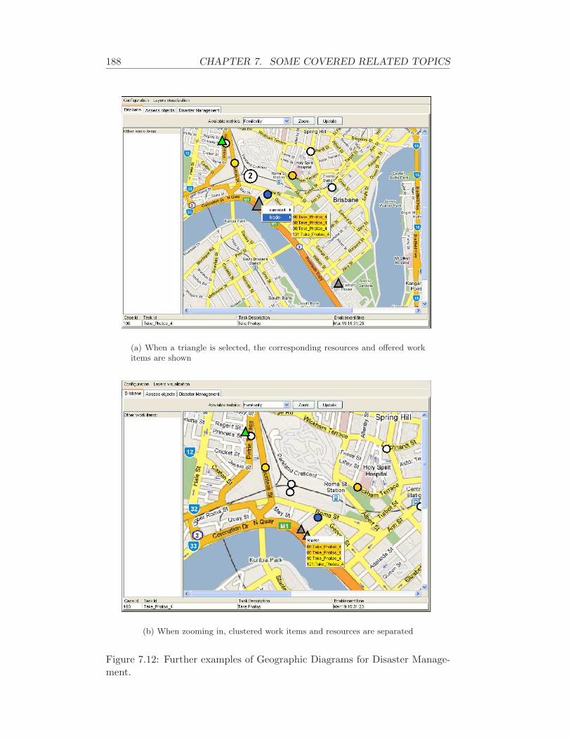
188 CHAPTER 7. SOME COVERED RELATED TOPICS
(a) When a triangle is selected, the corresponding resources and offered workitems are shown
(b) When zooming in, clustered work items and resources are separated
Figure 7.12: Further examples of Geographic Diagrams for Disaster Manage-ment.
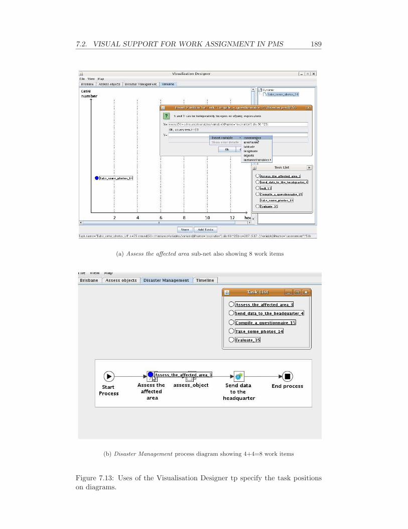
7.2. VISUAL SUPPORT FOR WORK ASSIGNMENT IN PMS 189
(a) Assess the affected area sub-net also showing 8 work items
(b) Disaster Management process diagram showing 4+4=8 work items
Figure 7.13: Uses of the Visualisation Designer tp specify the task positionson diagrams.

190 CHAPTER 7. SOME COVERED RELATED TOPICS
As already said, such tool allows to add and remove diagrams valuable forparticipants as well as to specify the position of tasks on such diagrams. Fig-ure 7.13(b) shows an example of how to specify dynamically task positions. Aresponsible person opens the YAWL process specification which she is willingto specify the position of the tasks of. This results in a new window is opened(Task List window in Figure 7.13(b)), which comprises all tasks existing inthe specification. At this point, users can drag and drop tasks on the definedmaps. In this way, users are specifying static positions for tasks. Users candefine dynamic positions through a specific window (Insert Position for TaskXYZ window in Figure 7.13(b)). It allows to specify some XQueries for defin-ing the X and Y component of the point where the corresponding task shouldbe positioned. These XQueries are defined on the process instance variablesand computed at run-time. Figure 7.13(b) depicts another example to definethe position of tasks on a process diagram. Specifically, the user is draggingand dropping the desired (static) position for task Assess the affected area.
7.2.10 Final Remarks
We have proposed a general visualisation that can aid users in selecting the“right” work item among a potentially large number of work items offered tothem. The framework uses the “diagram metaphor” to show the locations ofwork items and resources. The “distance metaphor” is used to show whichwork items are “close” (e.g., urgent, similar to earlier work items, or geograph-ically close). Both concepts are orthogonal and this provides a great deal offlexibility when it comes to presenting work to people. For example, one canchoose a geographical map to display work items and resources and use a dis-tance metric capturing urgency. The proposed framework was operationalisedas a component of the YAWL environment. By using well-defined interfacesthe component is generic so that in principle it could be exploited by otherPMSs as well under the provision that they are sufficiently “open” and providethe required interface methods. The component is also highly configurable,e.g., it allows resources to choose how distances should be computed for dotsrepresenting a number of work items and provides customizable support fordetermining which resources should be visible.
Future work on this concern may go in three directions:
1. Connecting this framework and its implementation to SmartPM. Thecurrent implementation works in concert with YAWL and a porting toSmartPM is planned. Although that would require SmartPM to provideall information needed, the framework is independent of any specificProcess Management System.
2. Connecting the current framework to geographical information systems
7.3. A SUMMARY 191
and process mining tools like ProM [135].
3. Geographical information systems store data based on locations and pro-cess mining can be used to extract data from event logs and visualise thison diagrams, e.g., it is possible to make a “movie” showing the evolutionof work items based on historic data.
7.3 A summary
This chapter has introduced some research topicsrelated to the process man-agement in pervasive scenarios. The first deals with the problem of synthesiz-ing a process schema according to the available services and distributing theorchestration among all of them. The second touches the topic of supportingprocess participants when choosing the next task to work on among the severalones they can be offered to. This second topic is fully available in a workflowproduct, specifically YAWL.

192 CHAPTER 7. SOME COVERED RELATED TOPICS

Chapter 8
Conclusion
The topic of this thesis work was directed to process management for highlydynamic and pervasive scenarios. Examples of pervasive scenarios includeemergency management, health-care or home automation. These scenariosare characterised by processes that are as complex as the traditional onesof business domains (e.g., loans, insurances). Therefore, the use of ProcessManagement Systems is indicated and very helpful.
Unfortunately, most of existing PMSs are intended for business scenariosand are not completely appropriate for the settings in which we are interested.Indeed, pervasive scenarios are turbulent a subject to an higher frequency ofunexpected contingencies with respect to business settings, where the environ-ment is mostly static and shows a foreseeable behaviour.
Therefore, PMSs for pervasive scenarios should provide a very high degreeof operational flexibility/adaptability. In this thesis, we have given a newdefinition of adaptability suitable for our intends in terms of gap. Adaptabilityis the ability of the system to reduce the gap between the virtual reality, themodel of the reality used to deliberate, and the physical reality, the real-worldstate with the actual values of conditions and outcomes. When the gap is sosignificant that the executing process cannot be carried out, the PMS shouldbe able to build a proper recovery plan able to reduce such a gap so as toallow the process to complete.
This thesis work proposes some techniques and frameworks to devise ageneral recovery method able to handle any kind of exogenous event, includ-ing those which were unforeseen. When doing that, we encountered mainchallenges in two directions: (i) conceiving an execution monitor able to de-termine when exogenous events occur and when they do not allow runningprocesses to terminate successfully; (ii) devising a recovery planner able tobuild a plan to allow the original process to terminate successfully. For thisaim, we have “borrowed” techniques from AI, such as Situation Calculus, In-
193

194 CHAPTER 8. CONCLUSION
diGolog as well as Execution Monitoring in agent and robot programming. Wehave applied such techniques to a different field, which required a significanteffort to conceptualize and formalize.
In order to show the feasibility of such techniques, we have conceived anddeveloped a proof-of-concept implementation called SmartPM by using an In-diGolog platform available. In order to make it usable in many pervasivescenarios, such as emergency management, SmartPM needs to work in set-tings based on Mobile Ad-hoc Networks (manets). In order to make thatpossible, we had to do some research work on topics related to mobile net-working. Specifically, we developed a manet layer to enable the multi-hopcommunication as well as we conceived and developed a specific technique topredict device disconnections before the actual occurrence (so as to be able torecover on time).
The next step on which we are currently working is to overcome the intrin-sical planning inefficiency of Prolog by making use of efficient state-of-the-artplanners.
There are a number of future research directions that arise from this thesis,and we have explained them in detail throughout this thesis itself. But, weare willing to summarize here the most relevant ones:
1. Working on integrating SmartPM with state-of-art planners in order toovercome the intrinsical planning inefficiency of Prolog. This step isanything but not easy and a lot of research is still ongoing. The mostchallenging issue is to convert Action Theories and IndiGolog programs ina way they can be given as input to planners (e.g., converting to PDDL).
2. Operationalizing the approach described in Chapter 6, more efficient,and integrating it with the framework currently implemented. Indeed,the idea would be that SmartPM should be able to understand processby process when the more efficient approach is applicable and, if notapplicable, it should continue using the current implemented approach.
3. Providing SmartPM with full-fledged work-list handlers to facilitate thetask distribution to human participants. We envision two two types ofwork-list handler: a version for ultra mobile devices and a lighter versionfor PDAs, “compact” but providing less features. First steps have beenalready done in these directions. The version for ultra mobile has beencurrently operationalized for a different PMS (see Section 7.2). The sameholds also for the PDA version that has been currently developed duringthis thesis in the ROME4EU Process Management System, a previousvaluable attempt to deal with unexpected deviations (see [7]).
4. Working on moving the central SmartPM engine to a distributed ap-proach, where every device contributes in the coordination of the process

195
execution. A first evaluation has been always done from a theoreticalperspective (see Section 7.1); it is not to concretely develop it and fit itwith the adaptability approach of SmartPM.

196 CHAPTER 8. CONCLUSION

Appendix A
The IndiGolog Code of theRunning Example
This appendix lists the code of the running example shown and discussed inChapters 4 and 5.
1 %%%%%%%%%%%%%%%%%%%%%%%%%%%%%%%%%%%%%%%%%%%2 %3 % FILE: aPMS/pms.pl4 %5 % AUTHOR : Massimiliano de Leoni, Andrea Marrella,6 % Sebastian Sardina, Stefano Valentini7 % TESTED : SWI Prolog 5.id_.1id_ http://www.swi-prolog.org8 %9 %%%%%%%%%%%%%%%%%%%%%%%%%%%%%%%%%%%%%%%%%%%%
10
11 :- dynamic controller/1.12
13 /* SOME DOMAIN-INDEPENDENT PREDICATES TO DENOTE THE VARIOUS OBJECTS OF14 INTEREST IN THE FRAMEWORK */15
16 /* Available services */17 services([1,2,3,4,5]).18 service(Srvc) :- domain(Srvc,services).19
20 /* Tasks defined in the process specification */21 tasks([TakePhoto,EvaluatePhoto,CompileQuest,Go,SendByGPRS]).22 task(Task) :- domain(Task,tasks).23
24 /* Capabilities relevant for the process of interest*/25 capabilities([camera,compile,gprs,evaluation]).26 capability(B) :- domain(B,capabilities).27
197

198 APPENDIX A. THE CODE OF THE RUNNING EXAMPLE
28 /* The list of identifiers that may be used to distinguish29 different istances of the same task */30 task_identifiers([id_1,id_2,id_3,id_4,id_5,id_6,id_7,id_8,id_9,id_10,31 id_11,id_12,id_13]).32 id(Id) :- domain(Id,task_identifiers).33
34 /* The capabilities required for each task */35 required(TakePhoto,camera).36 required(EvaluatePhoto,evaluation).37 required(CompileQuest,compile).38 required(SendByGPRS,gprs).39
40 /The capabilities provided by each service */41
42 provide(1,gprs).43 provide(1,evaluation).44 provide(2,compile).45 provide(2,evaluation).46 provide(2,camera).47 provide(3,compile).48 provide(4,evaluation).49 provide(4,camera).50 provide(5,compile).51
52 /* There is nothing to do caching on53 (required because cache 1 is static) */54 cache(_):-fail.55
56 /* Definition of predicate loc(i,j)57 identifying the current location of a service */58 gridsize(10).59 gridindex(V) :-60 gridsize(S),61 get_integer(0,V,S).62 location(loc(I,J)) :- gridindex(I), gridindex(J).63
64 /*The definition of integer numbers65 number(Srvc,M) :- get_integer(0,Srvc,M).66
67 /* square(X,Y): Y is the square of X */68 square(X,Y) :- Y is X * X.69
70 /* member(ELEM,LIST): returns true if ELEM is contained in LIST */71 member(ELEM,[HEAD|_]) :- ELEM=HEAD.72 member(ELEM,[_|TAIL]) :- member(ELEM,TAIL).73 listEqual(L1,L2) :- subset(L1,L2),subset(L2,L1).74

199
75 /* Definition of predicate workitem(Task,Id,I).76 It identifies a task Task with id Id and input I */77 listelem(workitem(Task,Id,I)) :- id(Id), location(I),78 member(Task,[Go,CompileQuest,EvaluatePhoto,TakePhoto]).79 listelem(workitem(SendByGPRS,Id,input)) :- id(Id).80
81 worklist([]).82 worklist([ELEM | TAIL]) :- worklist(TAIL),listelem(ELEM).83
84 /* DOMAIN-INDEPENDENT FLUENTS */85
86 /* Basically, there has to be some definition for predicates87 causes_true and causes_false, at least one88 for each. We have added the following dummy code: */89 causes_true(_,_,_) :- false.90 causes_false(_,_,_) :- false.91
92 /* Indicates that list LWrk of workitems has been assigned93 to service Srvc */94 rel_fluent(assigned(LWrk,Srvc)) :- worklist(LWrk),service(Srvc).95
96 /* assigned(LWrk,Srvc) holds after action assign(LWrk,Srvc) */97 causes_val(assign(LWrk,Srvc),assigned(LWrk,Srvc),true,true).98
99 /* assigned(LWrk,Id,Srvc) holds no longer after action100 release(LWrk,Srvc) */101 causes_val(release(LWrk,Srvc),assigned(LWrk,Srvc),false,true).102
103 /* Indicates that task Task with id Id has been begun104 by service Srvc */105 rel_fluent(enabled(Task,Id,Srvc)) :- task(Task), service(Srvc), id(Id).106
107 /* enabled(Task,Id,Srvc) becomes true if the service Srvc calls108 the exogenous action readyToStart((Task,Id,Srvc), indicating the109 starting of the task Task with id Id */110 causes_val(readyToStart((Task,Id,Srvc),enabled(Task,Id,Srvc),true,true).111
112 /* enabled(Task,Id,Srvc) holds no longer after service Srvc calls113 exogenous action finishedTask(Task,Id,Srvc,V)*/114 causes_val(finishedTask(Task,Id,Srvc,_),115 enabled(Task,Id,Srvc),false,true).116
117 /* free(Srvc) indicates that service Srvc118 has no task currently assigned */119 rel_fluent(free(Srvc)) :- service(Srvc).120
121 /* free(Srvc) holds after action release(LWrk,Srvc) */

200 APPENDIX A. THE CODE OF THE RUNNING EXAMPLE
122 causes_val(release(_X,Srvc),free(Srvc),true,true).123
124 /* free(Srvc) holds no longer after action assign(LWrk,Srvc) */125 causes_val(assign(_LWrk,Srvc),free(Srvc),false,true).126
127 /* ACTIONS and PRECONDITIONS */128
129 prim_action(assign(LWrk,Srvc)) :- worklist(LWrk),service(Srvc).130 poss(assign(LWrk,Srvc), true).131
132 prim_action(ackTaskCompletion(Task,Id,Srvc)) :-133 task(Task), service(Srvc), id(Id).134 poss(ackTaskCompletion(Task,Id,Srvc), neg(enabled(Task,Id,Srvc))).135
136 prim_action(start(Task,Id,Srvc,I)) :-137 listelem(workitem(Task,Id,I)), service(Srvc).138 poss(start(Task,Id,Srvc,I), and(enabled(Task,Id,Srvc),139 and(assigned(LWrk,Srvc),140 member(workitem(Task,Id,I),LWrk)))).141
142 prim_action(release(LWrk,Srvc)) :- worklist(LWrk),service(Srvc).143 poss(release(LWrk,Srvc), true).144
145 /* DOMAIN-DEPENDENT FLUENTS */146
147 /* at(Srvc) indicates that service Srvc is in position P */148 fun_fluent(at(Srvc)) :- service(Srvc).149 causes_val(finishedTask(Task,Id,Srvc,V),at(Srvc),150 loc(I,J),and(Task=Go,V=loc(I,J))).151
152 rel_fluent(evaluationOK(Loc)) :- location(Loc).153 causes_val(finishedTask(Task,Id,Srvc,V),evaluationOK(loc(I,J)), true,154 and(Task=EvaluatePhoto,155 and(V=(loc(I,J),OK),156 and(photoBuild(loc(I,J),N),157 N>3)))).158
159 fun_fluent(photoBuild(Loc)) :- location(Loc).160 causes_val(finishedTask(Task,Id,Srvc,V),photoBuild(Loc),N,161 and(Task=TakePhoto,162 and(V=(loc(I,J),Nadd),163 and(Nold=photoBuild(Loc),164 N is Nold+Nadd)))).165
166 rel_fluent(infoSent()).167 causes_val(finishedTask(Task,Id,Srvc,V),infoSent, true,168 and(Task=SendByGPRS,V=OK).
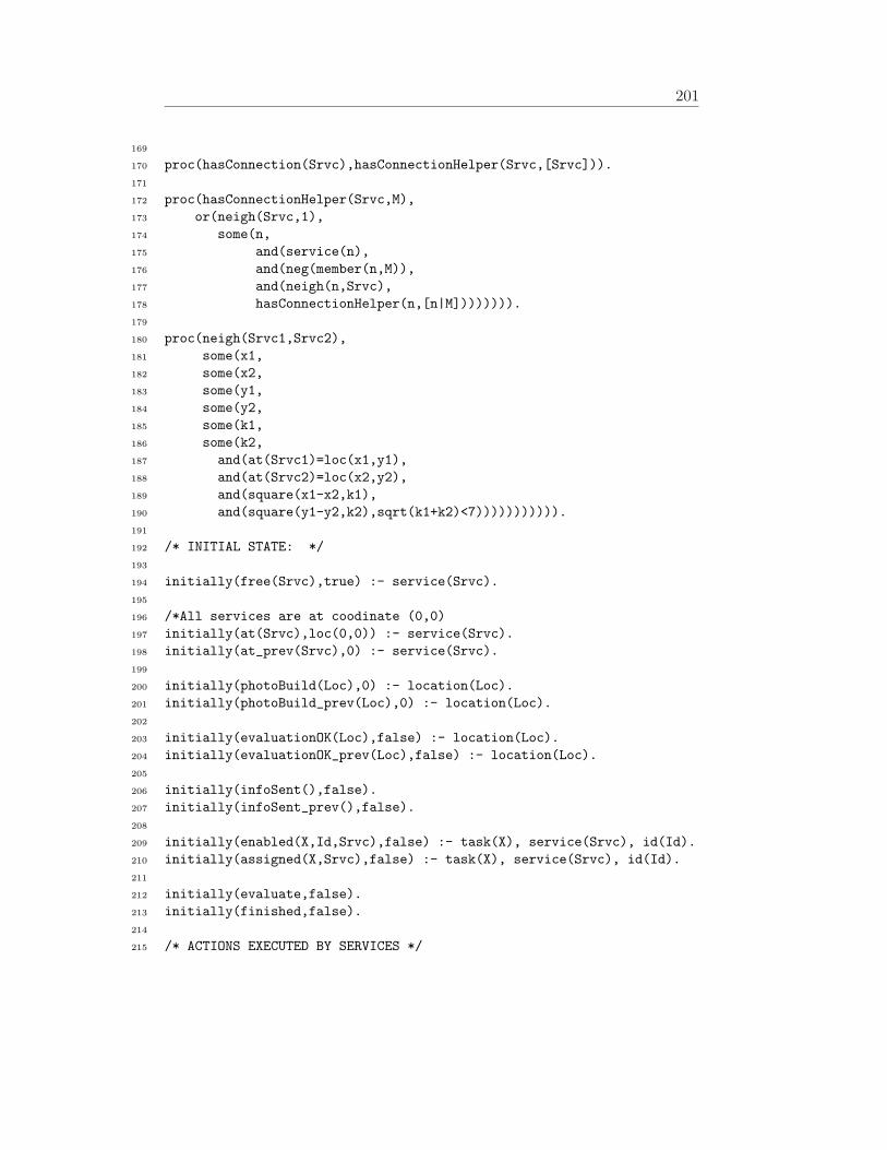
201
169
170 proc(hasConnection(Srvc),hasConnectionHelper(Srvc,[Srvc])).171
172 proc(hasConnectionHelper(Srvc,M),173 or(neigh(Srvc,1),174 some(n,175 and(service(n),176 and(neg(member(n,M)),177 and(neigh(n,Srvc),178 hasConnectionHelper(n,[n|M]))))))).179
180 proc(neigh(Srvc1,Srvc2),181 some(x1,182 some(x2,183 some(y1,184 some(y2,185 some(k1,186 some(k2,187 and(at(Srvc1)=loc(x1,y1),188 and(at(Srvc2)=loc(x2,y2),189 and(square(x1-x2,k1),190 and(square(y1-y2,k2),sqrt(k1+k2)<7))))))))))).191
192 /* INITIAL STATE: */193
194 initially(free(Srvc),true) :- service(Srvc).195
196 /*All services are at coodinate (0,0)197 initially(at(Srvc),loc(0,0)) :- service(Srvc).198 initially(at_prev(Srvc),0) :- service(Srvc).199
200 initially(photoBuild(Loc),0) :- location(Loc).201 initially(photoBuild_prev(Loc),0) :- location(Loc).202
203 initially(evaluationOK(Loc),false) :- location(Loc).204 initially(evaluationOK_prev(Loc),false) :- location(Loc).205
206 initially(infoSent(),false).207 initially(infoSent_prev(),false).208
209 initially(enabled(X,Id,Srvc),false) :- task(X), service(Srvc), id(Id).210 initially(assigned(X,Srvc),false) :- task(X), service(Srvc), id(Id).211
212 initially(evaluate,false).213 initially(finished,false).214
215 /* ACTIONS EXECUTED BY SERVICES */

202 APPENDIX A. THE CODE OF THE RUNNING EXAMPLE
216
217 exog_action(readyToStart((T,Id,Srvc))218 :- task(T), service(Srvc), id(Id).219 exog_action(finishedTask(T,Id,Srvc,_V))220 :- task(T), service(Srvc), id(Id).221
222 /* PREDICATES AND ACTIONS FOR MONITORING ADAPTATION */223
224 exog_action(disconnect(Srvc,loc(I,J)))225 :- service(Srvc), gridindex(I), gridindex(J).226
227 /* at(Srvc) assumes the value loc(I,J)228 after exogenous action disconnect(Srvc,loc(I,J))*/229 causes_val(disconnect(Srvc,loc(I,J)),at(Srvc),loc(I,J),true).230
231 prim_action(A) :- exog_action(A).232 poss(A,true) :- exog_action(A).233
234 causes_val(disconnect(Srvc,L),exogenous,true,true).235
236 /* Fluents in the previous situation */237 fun_fluent(at_prev(Srvc)) :- service(Srvc).238
239 fun_fluent(photoBuild_prev(Loc)) :- location(Loc).240
241 fun_fluent(evaluationOK_prev(Loc)) :- location(Loc).242
243 fun_fluent(infoSent_prev()).244
245 causes_val(disconnect(_,_),at_prev(Srvc),X,at(Srvc)=X)246 :- service(Srvc).247 causes_val(disconnect(_,_),248 photoBuild_prev(Srvc),X,photoBuild(Loc)=X) :- location(Loc).249 causes_val(disconnect(_,_),250 evaluationOK_prev(Loc),X,evaluationOK(Loc)=X) :- location(Loc).251 causes_val(disconnect(_,_),252 infoSent_prev(),X,infoSent()=X) :- service(Srvc).253
254 proc(hasConnection_prev(Srvc),hasConnectionHelper_prev(Srvc,[Srvc])).255
256 proc(hasConnectionHelper_prev(Srvc,M),257 or(neigh_prev(Srvc,1),258 some(n,259 and(service(n),and(neg(member(n,M)),260 and(neigh_prev(n,Srvc),hasConnectionHelper_prev(n,[n|M]))))))).261
262 proc(neigh_prev(Srvc1,Srvc2),

203
263 some(x1,264 some(x2,265 some(y1,266 some(y2,267 some(k1,268 some(k2,269 and(at_prev(Srvc1)=loc(x1,y1),270 and(at_prev(Srvc2)=loc(x2,y2),271 and(square(x1-x2,k1),272 and(square(y1-y2,k2),sqrt(k1+k2)<7))))))))))).273
274 /* ADAPTATION DOMAIN-INDEPENDENT FEATURES */275
276 prim_action(finish).277 poss(finish,true).278
279 rel_fluent(finished).280 causes_val(finish,finished,true,true).281
282 rel_fluent(exogenous).283 initially(exogenous,false).284
285 rel_fluent(adapted).286
287 prim_action(resetExo).288 poss(resetExo,true).289
290 causes_val(resetExo,exogenous,false,true).291 causes_val(adaptStart,adapted,false,true).292 causes_val(adaptFinish,adapted,true,true).293
294 prim_action(adaptFinish).295 poss(adaptFinish,true).296 prim_action(adaptStart).297 poss(adaptStart,true).298
299 fun_fluent(photoBuild_prev(Loc)) :- location(Loc).300
301 fun_fluent(evaluationOK_prev(Loc)) :- location(Loc).302
303 fun_fluent(infoSent_prev()).304
305
306 proc(relevant,307 and(some(Srvc,and(service(Srvc),308 and(hasConnection_prev(Srvc),309 neg(hasConnection(Srvc))))),

204 APPENDIX A. THE CODE OF THE RUNNING EXAMPLE
310 and(some(Loc,and(location(Srvc),311 and(photoBuild_prev(Srvc)=Y,312 neg(photoBuild(Srvc)=Y)))),313 and(some(Loc,and(location(Srvc),314 and(evaluationOK_prev(Srvc)=Z,315 neg(evaluationOK(Srvc)=Z)))),316 and(infoSent=W,neg(infoSent=W)))))317 ).318
319 proc(goalReached,neg(relevant)).320
321 proc(adapt, [adaptStart, ?(writeln(’about to adapt’)),322 pconc([adaptingProgram, adaptFinish],323 while(neg(adapted), [?(writeln(’waiting’)),wait]))324 ]325 ).326
327 proc(adaptingProgram, searchn([?(true),searchProgram],328 [assumptions([329 [ assign([workitem(Task,Id,_I)],Srvc),330 readyToStart((Task,Id,Srvc) ],331 start(Task,Id,Srvc,I),332 finishedTask(Task,Id,Srvc,I) ] ])333 ])334 ).335
336 proc(searchProgram, [star(pi([t,i,n],337 [ ?(isPickable([workitem(t,id_30,i)],n)),338 assign([workitem(t,id_30,i)],n),339 start(t,id_30,n,i),340 ackTaskCompletion(t,id_30,n),341 release([workitem(t,id_30,i)],n)342 ]343 ), 10),344 ?(goalReached)]345 ).346
347
348 /* ABBREVIATIONS - BOOLEAN FUNCTIONS */349
350 proc(isPickable(WrkList,Srvc),351 or(WrkList=[],352 and(free(Srvc),353 and(WrkList=[A|TAIL],354 and(listelem(A),355 and(A=workitem(Task,_Id,_I),356 and(isExecutable(Task,Srvc),

205
357 isPickable(TAIL,Srvc))))))358 )359 ).360
361 proc(isExecutable(Task,Srvc),362 and(findall(Capability,required(Task,Capability),A),363 and(findall(Capability,provide(Srvc,Capability),C),subset(A,C)))).364
365 % Translations of domain actions to real actions (one-to-one)366 actionNum(X,X).367
368 /* PROCEDURES FOR HANDLING THE TASK LIFE CYCLES */369
370 proc(manageAssignment(WrkList),371 [atomic([pi(n,[?(isPickable(WrkList,n)), assign(WrkList,n)])])]).372
373 proc(manageExecution(WrkList),374 pi(n,[?(assigned(WrkList,n)=true),manageExecutionHelper(WrkList,n)])).375
376 proc(manageExecutionHelper([],Srvc),[]).377
378 proc(manageExecutionHelper([workitem(Task,Id,I)|TAIL],Srvc),379 [start(Task,Id,Srvc,I), ackTaskCompletion(Task,Id,Srvc),380 manageExecutionHelper(TAIL,Srvc)]).381
382 proc(manageTermination(WrkList),383 [atomic([pi(n,[?(assigned(WrkList,n)=true), release(X,n)])])]).384
385 proc(manageTask(WrkList),386 [manageAssignment(WrkList),387 manageExecution(WrkList),388 manageTermination(WrkList)]).389
390
391 /* MAIN PROCEDURE FOR INDIGOLOG */392
393 proc(main, mainControl(N)) :- controller(N), !.394 proc(main, mainControl(3)). % default one395
396 proc(mainControl(5), prioritized_interrupts(397 [interrupt(and(neg(finished),exogenous), monitor),398 interrupt(true, [process,finish]),399 interrupt(neg(finished), wait)400 ])).401
402
403 proc(monitor,[?(writeln(’Monitor’)),
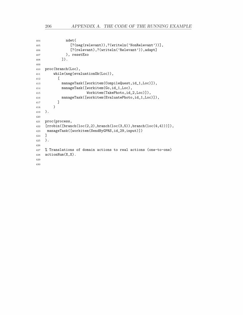
206 APPENDIX A. THE CODE OF THE RUNNING EXAMPLE
404 ndet(405 [?(neg(relevant)),?(writeln(’NonRelevant’))],406 [?(relevant),?(writeln(’Relevant’)),adapt]407 ), resetExo408 ]).409
410 proc(branch(Loc),411 while(neg(evaluationOk(Loc)),412 [413 manageTask([workitem(CompileQuest,id_1,Loc)]),414 manageTask([workitem(Go,id_1,Loc),415 Workitem(TakePhoto,id_2,Loc)]),416 manageTask([workitem(EvaluatePhoto,id_1,Loc)]),417 ]418 )419 ).420
421 proc(process,422 [rrobin([branch(loc(2,2),branch(loc(3,5)),branch(loc(4,4)))]),423 manageTask([workitem(SendByGPRS,id_29,input)])424 ]425 ).426
427 % Translations of domain actions to real actions (one-to-one)428 actionNum(X,X).429
430

Bibliography
[1] M. Adams, A. H. M. ter Hofstede, W. M. P. van der Aalst, and D. Ed-mond. Dynamic, extensible and context-aware exception handling forworkflows. In On the Move to Meaningful Internet Systems 2007:CoopIS, DOA, ODBASE, GADA, and IS Proceedings, Part I, volume4803 of Lecture Notes in Computer Science, pages 95–112. Springer,2007.
[2] I. Akyildiz, J. S. M. Ho, and Y. B. Lin. Movement-based Location Up-date and Selective Paging for PCS Networks. IEEE/ACM Transactionson Networking, 4(4):629–638, 1996.
[3] K. Andresen and N. Gronau. An Approach to Increase Adaptabilityin ERP Systems. In Managing Modern Organizations with InformationTechnology: Proceedings of the 2005 Information Resources Manage-ment Association International Conference, pages 883–885. Idea GroupPublishing, May 2005.
[4] J. Baier and S. McIlraith. On Planning with Programs that Sense. InKR’06: Proceedings of the 10th International Conference on Principlesof Knowledge Representation and Reasoning, pages 492–502, Lake Dis-trict, UK, June 2006. AAAI Press.
[5] J. A. Baier, C. Fritz, and S. A. McIlraith. Exploiting Procedural Do-main Control Knowledge in State-of-the-Art Planners. In Proceedingsof the International Conference on Automated Planning and Scheduling(ICAPS), pages 26–33. AAAI Press, 2007.
[6] S. Basagni, I. Chlamtac, V. R. Syrotiuk, and B. A. Woodward. A dis-tance routing effect algorithm for mobility (DREAM). In MobiCom ’98:Proceedings of the 4th annual ACM/IEEE international conference onMobile computing and networking, pages 76–84. ACM, 1998.
[7] D. Battista, M. de Leoni, A. Gaetanis, M. Mecella, A. Pezzullo,A. Russo, and C. Saponaro. ROME4EU: A Web Service-Based Process-Aware System for Smart Devices. In ICSOC ’08: Proceedings of the 6th
207

208 BIBLIOGRAPHY
International Conference on Service-Oriented Computing, pages 726–727. Springer-Verlag, 2008.
[8] B. Benatallah, M. Dumas, and Q. Sheng. Facilitating the rapid develop-ment and scalable orchestration of composite web services. Distributedand Parallel Databases, 17, 2005.
[9] D. Berardi, D. Calvanese, G. De Giacomo, R. Hull, and M. Mecella.Automatic composition of transition-based semantic web services withmessaging. In Proc. VLDB 2005, 2005.
[10] D. Berardi, D. Calvanese, G. De Giacomo, M. Lenzerini, and M. Mecella.Automatic Service Composition Based on Behavioural Descriptions. In-ternational Journal of Cooperative Information Systems, 14(4):333–376,2005.
[11] D. Berardi, D. Calvanese, G. De Giacomo, and M. Mecella. Composingweb services with nondeterministic behavior. In Proc. ICWS 2006, 2006.
[12] P. Berens. Process-Aware Information Systems, chapter Case handlingwith FLOWer: Beyond workflow. John Wiley & Sons, 2005.
[13] J. O. Berger. Statistical Decision Theory and Bayesian Analysis.Springer, 1985.
[14] G. Bertelli, M. de Leoni, M. Mecella, and J. Dean. Mobile Ad hoc Net-works for Collaborative and Mission-critical Mobile Scenarios: a Prac-tical Study. In WETICE’08: Proceedings of the 17th IEE InternationalWorkshops on Enabling Technologies: Infrastructure for collaborationenterprises, pages 157–152. IEEE Publisher, 2008.
[15] R. Bobrik, M. Reichert, and T. Bauer. View-based process visualization.In Proceedings of the 5th International Conference on Business ProcessManagement BPM 2007, volume 4714 of LNCS, pages 88–95. Springer,2007.
[16] A. Borgida and T. Murata. Tolerating exceptions in workflows: a uni-fied framework for data and processes. In WACC ’99: Proceedings ofthe international joint conference on Work activities coordination andcollaboration, pages 59–68. ACM, 1999.
[17] R. Brown and H.-Y. Paik. Resource-centric worklist visualisation. InProceedings of OTM Confederated International Conferences, CoopIS,DOA, and ODBASE 2005, volume 3760 of LNCS, pages 94–111.Springer, 2005.

BIBLIOGRAPHY 209
[18] D. Calvanese, G. De Giacomo, M. Lenzerini, M. Mecella, and F. Patrizi.Automatic Service Composition and Synthesis: the Roman Model. IEEEData Engineering Bulletin, 31(3):18–22, 2008.
[19] F. Casati, S. Ceri, B. Pernici, and G. Pozzi. Workflow Evolution. Data& Knowledge Engineering, 24(3):211–238, 1998.
[20] F. Casati, S. Ilnicki, L. jie Jin, V. Krishnamoorthy, and M.-C. Shan.Adaptive and Dynamic Service Composition in eFlow. In CAiSE2000:Proceedings of 12th International Conference Advanced Information Sys-tems Engineering, volume 1789 of Lecture Notes in Computer Science,pages 13–31. Springer, 2000.
[21] T. Catarci, F. Cincotti, M. de Leoni, M. Mecella, and G. Santucci.Smart homes for all: Collaborating services in a for-all architecturefor domotics. In CollaborateCom’08: Proc. of The 4th InternationalConference on Collaborative Computing: Networking, Applications andWorksharing. ACM Press, 2009. To appear.
[22] T. Catarci, M. de Leoni, F. De Rosa, M. Mecella, A. Poggi, S. Dust-dar, L. Juszczyk, H. Truong, and G. Vetere. The WORKPAD P2PService-Oriented Infrastracture for Emergency Management. In WET-ICE ’07: Proceedings of the 16th IEEE International Workshops on En-abling Technologies: Infrastructure for Collaborative Enterprises, Wash-ington, DC, USA, 2007. IEEE Computer Society.
[23] T. Catarci, M. de Leoni, A. Marrella, M. Mecella, G. Vetere, B. Salva-tore, S. Dustdar, L. Juszczyk, A. Manzoor, and H.-L. Truong. PervasiveSoftware Environments for Supporting Disaster Responses. IEEE Inter-net Computing, 12(1):26–37, 2008.
[24] T. Catarci, F. De Rosa, M. de Leoni, M. Mecella, M. Angelaccio,S. Dustdar, A. Krek, G. Vetere, Z. M. Zalis, B. Gonzalvez, and G. Iiri-tano. WORKPAD: 2-Layered Peer-to-Peer for Emergency Managementthrough Adaptive Processes. In CollaborateCom 2006: Proceedings ofthe 2nd International Conference on Collaborative Computing: Network-ing, Applications and Worksharing. IEEE Computer Society, 2006.
[25] G. Chafle, S. Chandra, V. Mann, and M. G. Nanda. Decentralized or-chestration of composite web services. In Proc. WWW 2004 – AlternateTrack Papers & Posters, 2004.
[26] D. Chiu, Q. Li, , and K. Karlapalem. A logical framework for excep-tion handling in ADOME workflow management system. In CAiSE2000:
210 BIBLIOGRAPHY
Proceedings of 12th International Conference Advanced Information Sys-tems Engineering, volume 1789 of Lecture Notes in Computer Science,pages 110–125. Springer, 2000.
[27] Cosa GmbH. COSA BPM product description. http://www.cosa.de/project/docs/en/COSA57-Productdescription.pdf, July 2008.Prompted on 1 February, 2009.
[28] F. D’Aprano, M. de Leoni, and M. Mecella. Emulating mobile ad-hocnetworks of hand-held devices: the octopus virtual environment. InMobiEval ’07: Proceedings of the 1st international workshop on Systemevaluation for mobile platforms, pages 35–40, New York, NY, USA, 2007.ACM.
[29] G. De Giacomo, Y. Lesperance, H. J. Levesque, and S. Sardina. In-diGolog: A High-Level Programming Language for Embedded ReasoningAgents, chapter in Multi-Agent Programming: Languages, Platforms andApplications. Rafael H. Bordini, Mehdi Dastani, Jurgen Dix, Amal ElFallah-Seghrouchni (Eds.). Springer, 2009. To appear.
[30] G. De Giacomo and H. J. Levesque. An incremental interpreter for high-level programs with sensing. In H. J. Levesque and F. Pirri, editors,Logical Foundations for Cognitive Agents: Contributions in Honor ofRay Reiter, pages 86–102. Springer, Berlin, 1999.
[31] G. De Giacomo, R. Reiter, and M. Soutchanski. Execution Monitoringof High-Level Robot Programs. In KR’98: Proceedings of the Sixth In-ternational Conference on Principles of Knowledge Representation andReasoning, pages 453–465, 1998.
[32] G. De Giacomo and S. Sardina. Automatic synthesis of new behaviorsfrom a library of available behaviors. In IJCAI’07: Proceedings of 20thInternational Joint Conference on Artificial Intelligence, pages 1866–1871, Hyderabad, India, 2007.
[33] M. de Leoni, G. De Giacomo, Y. Lesperance, and M. Mecella. On-lineAdaptation of Sequential Mobile Processes Running Concurrently. InSAC ’09: Proceedings of the 2009 ACM Symposium on Applied Com-puting. ACM Press, 2009. To appear.
[34] M. de Leoni, F. De Rosa, S. Dustdar, and M. Mecella. Resource dis-connection management in MANET driven by process time plan. InAutonomics ’07: Proceedings of the 1st ACM/ICST International Con-ference on Autonomic Computing and Communication Systems. ACM,2007.

BIBLIOGRAPHY 211
[35] M. de Leoni, F. De Rosa, A. Marrella, A. Poggi, A. Krek, and F. Manti.Emergency Management: from User Requirements to a Flexible P2PArchitecture. In B. Van de Walle, P. Burghardt, and C. Nieuwenhuis,editors, Proceedings of the 4th International Conference on InformationSystems for Crisis Response and Management ISCRAM2007, 2007.
[36] M. de Leoni, F. De Rosa, and M. Mecella. MOBIDIS: A Pervasive Ar-chitecture for Emergency Management. In WETICE ’06: Proceedingsof the 15th IEEE International Workshops on Enabling Technologies:Infrastructure for Collaborative Enterprises, pages 107–112. IEEE Com-puter Society, 2006.
[37] M. de Leoni, S. Dustdar, and A. H. M. ter Hofstede. Introduction to the1st International Workshop on Process Management for Highly Dynamicand Pervasive Scenarios (PM4HDPS’08). In BPM 2008 Workshops, vol-ume 17 of LNBIP, pages 241–243. Springer-Verlag, 2009.
[38] M. de Leoni, S. R. Humayoun, M. Mecella, and R. Russo. A BayesianApproach for Disconnection Management in Mobile Ad Hoc Networks.Ubiquitous Computing and Communication Journal, CPE, March 2008.
[39] M. de Leoni, A. Marrella, M. Mecella, S. Valentini, and S. Sardina. Coor-dinating Mobile Actors in Pervasive and Mobile Scenarios: An AI-basedApproach. In WETICE’08: Proceedings of the 17th IEE InternationalWorkshops on Enabling Technologies: Infrastructure for collaborationenterprises, pages 82–88. IEEE Publisher, 2008.
[40] M. de Leoni, M. Mecella, and G. De Giacomo. Highly Dynamic Adap-tation in Process Management Systems Through Execution Monitoring.In BPM’07: Proceedings of the 5th Internation Conference on BusinessProcess Management, volume 4714 of Lecture Notes in Computer Sci-ence, pages 182–197. Springer, 2007.
[41] M. de Leoni, M. Mecella, and R. Russo. A bayesian approach fordisconnection management in mobile ad hoc networks. In WETICE’07: Proceedings of the 16th IEEE International Workshops on EnablingTechnologies: Infrastructure for Collaborative Enterprises, pages 62–67,Washington, DC, USA, 2007. IEEE Computer Society.
[42] M. de Leoni, W. M. P. van der Aalst, and A. H. M. ter Hofstede. VisualSupport for Work Assignment in Process-Aware Information Systems.In Proceedings of the 6th International Conference on Business ProcessManagement (BPM’08), Milan, Italy, September 2-4, volume 5240 ofLecture Notes in Computer Science. Springer, 2008.
212 BIBLIOGRAPHY
[43] J. Dehnert and P. Rittgen. Relaxed Soundness of Business Processes. InProceedings of 19th International Conference on Advanced InformationSystems Engineering, 19th International, volume 2068 of Lecture Notesin Computer Science, pages 157–170. Springer, 2001.
[44] Y. Dong and Z. Shen-sheng. Approach for workflow modeling usingpi-calculus. Journal of Zhejiang University SCIENCE, 4(6):643–650,November 2003.
[45] O. V. Drugan, T. Plagemann, and E. Munthe-Kaas. Non-intrusive neigh-bor prediction in sparse manets. In SECON 2007: Proceedings of theFourth Annual IEEE Communications Society Conference on Sensor,Mesh and Ad Hoc Communications and Networks, pages 172–182. IEEE,2007.
[46] M. Dumas, W. M. P. van der Aalst, and A. H. M. ter Hofstede. Process-Aware Information Systems: Bridging People and Software ThroughProcess Technology. Wiley, September 2005.
[47] W. Feler. An Introduction to Probability Theory and its Applications.Willey, 2nd edition, 1971.
[48] J. Flynn, H. Tewari, D., and O’Mahony. Jemu: A Real Time EmulationSystem for Mobile Ad Hoc Networks. In Proceedings of 1st Joint IEI/IEESymposium on Telecommunications Systems Research, 2001.
[49] D. Fox, J. Hightower, L. Lao, D. Schulz, and G. Borriello. BayesianFilters for Location Estimation. IEEE Pervasive Computing, 2(3):24 –33, 2003.
[50] M. Fox and D. Long. PDDL2.1: An Extension to PDDL for ExpressingTemporal Planning Domains. Journal of Artificial Intelligence Research(JAIR), 20:61–124, 2003.
[51] C. Fritz, J. A. Baier, and S. A. McIlraith. ConGolog, Sin Trans: Com-piling ConGolog into Basic Action Theories for Planning and Beyond.In KR2008: Proceedings of the Eleventh International Conference onPrinciples of Knowledge Representation and Reasoning, pages 600–610.AAAI Press, 2008.
[52] M. Ghallab, D. Nau, and P. Traverso. Automated Planning: Theory andPractice. Morgan Kaufmann Publishers, May 2004.
[53] G. D. Giacomo, M. de Leoni, M. Mecella, and F. Patrizi. AutomaticWorkflows Composition of Mobile Services. In ICWS’07: Proceedings of

BIBLIOGRAPHY 213
the 2007 IEEE International Conference on Web Services, pages 823–830. IEEE Computer Society, 2007.
[54] K. Goser, M. Jurisch, H. Acker, U. Kreher, M. Lauer, S. Rinderle,M. Reichert, and P. Dadam. Next-generation Process Managementwith ADEPT2. In Proceedings of the BPM Demonstration Programat the Fifth International Conference on Business Process Management(BPM’07), volume 272 of CEUR Workshop Proceedings. CEUR-WS.org,2007.
[55] L. Guibas and J. Stolfi. Primitives for the manipulation of general sub-divisions and the computation of voronoi. ACM Trans. Graph., 4(2):74–123, 1985.
[56] C. W. Gunther, M. Reichert, and W. M. van der Aalst. Supporting Flex-ible Processes with Adaptive Workflow and Case Handling. In WET-ICE’08: Proceedings of the 17th IEEE International Workshops on En-abling Technologies: Infrastructures for Collaborative Enterprises, 2008.
[57] P. Gupta and P. R. Kumar. The capacity of wireless networks. IEEETransactions on Information Theory, IT-46(2):388–404, March 2000.
[58] D. Hadaller, S. Keshav, T. Brecht, and S. Agarwal. Vehicular oppor-tunistic communication under the microscope. In MobiSys ’07: Proceed-ings of the 5th international conference on Mobile systems, applicationsand services, pages 206–219. ACM Press, 2007.
[59] C. Hagen and G. Alonso. Exception handling in workflow managementsystems. IEEE Transactions on Software Engineering, 26(10):943–958,October 2000.
[60] G. Hansen. Automated Business Process Reengineering: Using thePower of Visual Simulation Strategies to Improve Performance andProfit. Prentice-Hall, Englewood Cliffs, 1997.
[61] D. Harel, D. Kozen, and J. Tiuryn. Dynamic Logic. The MIT Press,2000.
[62] G. Harik, E. Cantu-Paz, D. E. Goldberg, and B. L. Miller. The gam-bler’s ruin problem, genetic algorithms, and the sizing of populations.Evolutionary Computation, 7(3):231–253, 1999.
[63] S. L. Hickmott, J. Rintanen, S. Thiebaux, and L. B. White. Planningvia petri net unfolding. In IJCAI 2007: Proceedings of the 20th Inter-national Joint Conference on Artificial Intelligence, pages 1904–1911.AAAI Press, 2007.

214 BIBLIOGRAPHY
[64] J. Hidders, M. Dumas, W. M. P. van der Aalst, A. H. M. ter Hofstede,and J. Verelst. When are two workflows the same? In CATS ’05: Pro-ceedings of the 2005 Australasian symposium on Theory of computing,pages 3–11. Australian Computer Society, Inc., 2005.
[65] R. Hull and J. Su. Tools for design of composite web services. In Proc.SIGMOD 2004, pages 958–961, 2004.
[66] S. R. Humayoun, T. Catarci, M. de Leoni, A. Marrella, M. Mecella,M. Bortenschlager, and R. Steinmann. Designing Mobile Systems inHighly Dynamic Scenarios. The WORKPAD Methodology. Journal onKnowledge, Technology & Policy, 2009. To appear.
[67] S. R. Humayoun, T. Catarci, M. de Leoni, A. Marrella, M. Mecella,M. Bortenschlager, and R. Steinmann. The workpad user interface andmethodology: Developing smart and effective mobile applications foremergency operators. In HCI International 2009: Proceedings of 13thInternational Conference on Human-Computer Interaction, volume 5616of Lecture Notes in Computer Science. Springer, 2009.
[68] IBM Inc. An introduction to WebSphere Process Server andWebSphere Integration Developer. ftp://ftp.software.ibm.com/software/integration/wps/library/WSW14021-US%EN-01.pdf, May2008. Prompted on 1 February, 2009.
[69] A. Jardosh, E. M. Belding-Royer, K. C. Almeroth, and S. Suri. Towardsrealistic mobility models for mobile ad hoc networks. In MobiCom ’03:Proceedings of the 9th annual international conference on Mobile com-puting and networking, pages 217–229. ACM Press, 2003.
[70] K. Jensen. Coloured Petri Nets; Basic Concepts, Analysis Methods andPractical Use. Springer, 2nd edition, 1997.
[71] D. B. Johnson, D. A. Maltz, and J. Broch. DSR: The Dynamic SourceRouting Protocol for Multi-Hop Wireless Ad Hoc Networks. In C. E.Perkins, editor, Ad Hoc Networking, pages 139–172. Addison-Wesley,2001.
[72] B. Kiepuszewski, A. H. M. t. Hofstede, and C. Bussler. On StructuredWorkflow Modelling. In CAiSE ’00: Proceedings of the 12th Interna-tional Conference on Advanced Information Systems Engineering, pages431–445, London, UK, 2000. Springer-Verlag.
[73] M. Kinateder. Sap advanced workflow techniques. https://www.sdn.sap.com/irj/servlet/prt/portal/prtroot/docs/

BIBLIOGRAPHY 215
library/uui%d/82d03e23-0a01-0010-b482-dccfe1c877c4, 2006.Prompted on 1 February, 2009.
[74] E. Kindler. On the semantics of EPCs: Resolving the vicious circle.Data & Knowledge Engineering, 56(1):23–40, 2006.
[75] Y.-B. Ko and N. H. Vaidya. Location-Aided Routing (LAR) in MobileAd hoc Networks. Wireless Networks, 6:307––321, 2000.
[76] R. A. Kowalski. Using meta-logic to reconcile reactive with rationalagents. Meta-logics and logic programming, pages 227–242, 1995.
[77] A. Kumar, W. Aalst, and H. Verbeek. Dynamic Work Distribution inWorkflow Management Systems: How to Balance Quality and Perfor-mance? Journal of Management Information Systems, 18(3):157–193,2002.
[78] O. Kupferman and M. Y. Vardi. Synthesizing distributed systems. InProc. of LICS 2001, page 389, 2001.
[79] B. Kusy, J. Sallai, G. Balogh, A. Ledeczi, V. Protopopescu, J. Tolliver,F. DeNap, and M. Parang. Radio interferometric tracking of mobilewireless nodes. In MobiSys ’07: Proceedings of the 5th internationalconference on Mobile systems, applications and services, pages 139–151.ACM Press, 2007.
[80] U. Kuter, E. Sirin, D. Nau, B. Parsia, and J. Hendler. Information gath-ering during planning for web service composition. In Proc. Workshopon Planning and Scheduling for Web and Grid Services, 2004.
[81] M. La Rosa, M. Dumas, A. H. M. ter Hofstede, J. Mendling, andF. Gottschalk. Beyond Control-Flow: Extending Business Process Con-figuration to Roles and Objects. In ER 2008: Proceedings of 27th In-ternational Conference on Conceptual Modeling, volume 5231 of LectureNotes in Computer Science, pages 199–215, 2008.
[82] M. Lankhorst. Enterprise Architecture at Work: Modelling, Communi-cation, and Analysis. Springer, 2005.
[83] Y. Lesperance and H.-K. Ng. Integrating Planning into Reactive High-Level Robot Programs. In Proceedings of the Second International Cog-nitive Robotics Workshop (in conjunction with ECAI 2000), pages 49–54,August 2000.
[84] J. Li, C. Blake, D. S. J. De Couto, H. I. Lee, and R. Morris. Capacityof Ad Hoc Wireless Networks. In Proc. 7th International Conference
216 BIBLIOGRAPHY
on Mobile Computing and Networking (MOBICOM 2001), pages 61–69,2001.
[85] B. Liang and Z. J. Haas. Predictive Distance-based Mobility Manage-ment for Multidimensional PCS Networks. IEEE/ACM Transactions onNetworking, 11(5):718–732, 2003.
[86] P. Luttighuis, M. Lankhorst, R. Wetering, R. Bal, and H. Berg. Visual-ising business processes. Computer Languages, 27(1/3):39–59, 2001.
[87] L. T. Ly, S. Rinderle, and P. Dadam. Integration and verification ofsemantic constraints in adaptive process management systems. Data &Knowledge Engineering, 64(1):3–23, 2008.
[88] J. Macker, W. Chao, and J. Weston. A low-cost, IP-based Mobile Net-work Emulator (MNE). In MILCOM’03: Proceedings of the MilitaryCommunications Conference, volume 1, pages 481– 486. IEEE Press,2003.
[89] P. Mahadevan, A. Rodriguez, D. Becker, and A. Vahdat. Mobinet: ascalable emulation infrastructure for ad hoc and wireless networks. InWiTMeMo ’05: The 2005 workshop on Wireless traffic measurementsand modeling, pages 7–12, Berkeley, CA, USA, 2005. USENIX Associa-tion.
[90] D. Mahrenholz and S. Ivanov. Real-time network emulation with ns-2.In DS-RT ’04: Proceedings of the 8th IEEE International Symposium onDistributed Simulation and Real-Time Applications, pages 29–36. IEEEComputer Society, 2004.
[91] B. S. Manoj and A. Hubenko Baker. Communication Challenges inEmergency Response. Communincation of ACM, 50(3):51–53, 2007.
[92] D. V. McDermott. The 1998 AI Planning Systems Competition. AIMagazine, 21(2):35–55, 2000.
[93] S. A. McIlraith and T. C. Son. Adapting Golog for composition ofsemantic web services. In Proc. KR 2002, pages 482–496, 2002.
[94] M. Mecella and B. Pernici. Cooperative information systems based ona service oriented approach. Journal of Interoperability in Business In-formation Systems, 1(3), 2006.
[95] B. Medjahed, A. Bouguettaya, and A. K. Elmagarmid. Composing webservices on the semantic web. VLDB Journal, 12(4):333 – 351, 2003.

BIBLIOGRAPHY 217
[96] J. Mendling and W. M. van der Aalst. Formalization and Verificationof EPCs with OR-Joins Based on State and Context. In Proceedings of19th International Conference on Advanced Information Systems Engi-neering, 19th International, volume 4495 of Lecture Notes in ComputerScience. Springer, 2007.
[97] J. Mendling, H. M. W. Verbeek, B. F. van Dongen, W. M. P. van derAalst, and G. Neumann. Detection and prediction of errors in EPCs ofthe SAP reference model. Data & Knowledge Engineering, 64(1):312–329, 2008.
[98] S. Menotti. SPIDE A Smart Process IDE for Emergency Operators.Master’s thesis, Faculty of Computer Engineering - SAPIENZA Univer-sita di Roma, 2008. Supervisor: Dr. Massimo Mecella. In English.
[99] R. Milner. A Calculus of Communicating Systems, volume 92 of LectureNotes in Computer Science. Springer, 1980.
[100] R. Milner. Communication and Concurrency. Prentice Hall, Inc., UpperSaddle River, NJ, USA, 1989.
[101] R. Muller, U. Greiner, and E. Rahm. AGENTWORK: a workflow sys-tem supporting rule-based workflow adaptation. Data & Knowledge En-gineering, 51(2):223–256, 2004.
[102] A. L. Murphy, G. P. Picco, and G. C. Roman. LIME: A CoordinationModel and Middleware Supporting Mobility of Hosts and Agents. ACMTransactions on Software Engineering and Methodologies, 15(3):279 –328, 2006.
[103] D. Niculescu and B. Nath. Position and Orientation in ad hoc Networks.Elsevier Journal of Ad Hoc Networks, 2(2):133–151, April 2004.
[104] R. P. P. Nikitin and D. Stancil. Efficient Simulation of Ricean Fadingwithin a Packet Simulator. In Proceedings of the 51st Vehicular Tech-nology Conference, pages 764–767. IEEE, 2000.
[105] Object Management Group. Business Process Modeling Nota-tion. http://www.bpmn.org/Documents/OMG%20Final%20Adopted%20BPMN%201-0%20Spec%%2006-02-01.pdf, February 2006. Promptedon 16 February, 2009.
[106] S. Papanastasiou, L. M. Mackenzie, M. Ould-Khaoua, and V. Charis-sis. On the interaction of TCP and Routing Protocols in MANETs.In AICT-ICIW ’06: Proceedings of the Advanced Int’l Conference on

218 BIBLIOGRAPHY
Telecommunications and Int’l Conference on Internet and Web Applica-tions and Services, page 62, Washington, DC, USA, 2006. IEEE Com-puter Society.
[107] C. E. Perkins and P. Bhagwat. Highly Dynamic Destination-SequencedDistance-Vector Routing (DSDV) for Mobile Computers. In Proc. SIG-COMM 94, 1994.
[108] C. Petri. Communication with Automata. PhD thesis, Insitut fur In-strumentelle Mathematik - Universitat Bonn, 1962.
[109] A. Pnueli and R. Rosner. On the synthesis of a reactive module. InProc. POPL 1989, pages 179–190, 1989.
[110] A. Pnueli and R. Rosner. Distributed reactive systems are hard to syn-thesize. In Proc. of FOCS 1990, pages 746–757, 1990.
[111] J. L. Pollock. The logical foundations of goal-regression planning inautonomous agents. Artificial Intelligence, 106(2):267–334, 1998.
[112] T. V. Project. The ns Manual. http://isi.edu/nsnam/ns/ns-documentation.html, 01 2009.
[113] F. Puhlmann. Soundness Verification of Business Processes Specified inthe Pi-Calculus. In On the Move to Meaningful Internet Systems 2007:CoopIS, DOA, ODBASE, GADA, and IS Proceedings, Part I, volume4803 of Lecture Notes in Computer Science, pages 6–23. Springer, 2007.
[114] F. Puhlmann and M. Weske. Using the π-calculus for Formalizing Work-flow Patterns. In Proceedings of the 3rd International Conference onBusiness Process Management, BPM 2006, volume 3649 of Lecture Notesin Computer Science, pages 153–168. Springer, 2005.
[115] M. Puzar and T. Plagemann. NEMAN: A Network Emulator for MobileAd-Hoc Networks. In ConTel 2005: Proceedings of the 8th InternationalConference on Telecommunications, pages 155–161. IEEE Press, June2005.
[116] M. Qin, R. Zimmermann, and L. S. Liu. Supporting multimedia stream-ing between mobile peers with link availability prediction. In MULTIME-DIA ’05: Proceedings of the 13th annual ACM international conferenceon Multimedia, pages 956–965, New York, NY, USA, 2005. ACM.
[117] M. Reichert and P. Dadam. ADEPTflex - Supporting Dynamic Changesof Workflows Without Losing Control. Journal of Intelligent InformationSystems (JIIS), 10(2):93–129, 1998.

BIBLIOGRAPHY 219
[118] M. Reichert, S. Rinderle, U. Kreher, and P. Dadam. Adaptive Pro-cess Management with ADEPT2. In ICDE ’05: Proceedings of the 21stInternational Conference on Data Engineering, pages 1113–1114. IEEEComputer Society, 2005.
[119] R. Reiter. Knowledge in Action: Logical Foundations for Specifying andImplementing Dynamical Systems. MIT Press, September 2001.
[120] N. Russell, W. M. P. van der Aalst, A. H. M. ter Hofstede, and D. Ed-mond. Workflow resource patterns: Identification, representation andtool support. In Proceedings of 17th International Conference CAiSE2005, volume 3520 of LNCS, pages 216–232. Springer, 2005.
[121] S. Sardina, G. De Giacomo, Y. Lesperance, and H. J. Levesque. On theSemantics of Deliberation in Indigolog—from Theory to Implementa-tion. Annals of Mathematics and Artificial Intelligence, 41(2-4):259–299,2004.
[122] S. Sardina, F. Patrizi, and G. De Giacomo. Automatic synthesis of aglobal behavior from multiple distributed behaviors. In AAAI 2007:Proceedings of the Twenty-Second AAAI Conference on Artificial Intel-ligence, pages 1063–1069. AAAI Press, 2007.
[123] H. Schonenberg, R. Mans, N. Russell, N. Mulyar, and W. M. P. van derAalst. Towards a Taxonomy of Process Flexibility. In Proceedings of theForum at the CAiSE’08 Conference, volume 344 of CEUR WorkshopProceedings, pages 81–84. CEUR-WS.org, 2008.
[124] A. Streit, B. Pham, and R. Brown. Visualization support for managinglarge business process specifications. In Proceedings of the 3rd Interna-tional Conference on Business Process Management BPM 2005, volume3649 of LNCS, pages 205–219. Springer, 2005.
[125] G. Tagni, A. ten Teije, and F. van Harmelen. Reasoning about re-pairability of workflows at design time. In Proceedings of the 1st Inter-national Workshop on QoS in Self-healing Web Services (QSWS-08), inconjunction with BPM 2008 6th International Conference on BusinessProcess Management (BPM 2008), Lecture Notes in Computer Science.Springer, 2009.
[126] T. O. Team. OMNET++ User Manual. http://www.omnetpp.org/doc/manual/usman.html, 2006.
[127] Tibco Software Inc. Introduction to TIBCO iProcess Suite.www.tibco.com/resources/software/bpm/tibco\_iprocess\_suite\_whitepaper%.pdf, 2008. Prompted on 1 February, 2009.

220 BIBLIOGRAPHY
[128] P. Traverso and M. Pistore. Automated composition of semantic webservices into executable processes. In Proc. ISWC 2004, volume 3298 ofLNCS, pages 380–394. Springer, 2004.
[129] W. M. van der Aalst and P. Berens. Beyond Workflow Management:Product-Driven Case Handling. In GROUP2001: Proceedings of theInternational ACM SIGGROUP Conference on Supporting Group Work,pages 42–51. ACM Press, 2001.
[130] W. M. van der Aalst, M. Weske, and D. Grunbauer. Case Handling:A New Paradigm for Business Process Support. Data and KnowledgeEngineering, 53:129–162, 2005.
[131] W. M. P. van der Aalst. The application of petri nets to workflowmanagement. Journal of Circuits, Systems, and Computers, 8(1):21–66,1998.
[132] W. M. P. van der Aalst. Workflow verification: Finding control-flowerrors using petri-net-based techniques. In Proceedings of Business Pro-cess Management, Models, Techniques, and Empirical Studies, pages161–183, London, UK, 2000. Springer-Verlag.
[133] W. M. P. van der Aalst and A. H. M. ter Hofstede. YAWL: yet anotherworkflow language. Information Systems, 30(4):245–275, 2005.
[134] W. M. P. van der Aalst, A. H. M. ter Hofstede, B. Kiepuszewski, andA. P. Barros. Workflow Patterns. Distributed and Parallel Databases,14(1):5–51, 2003.
[135] W. M. P. van der Aalst, B. van Dongen, G. Christian, R. S. Mans,A. Alva de Medeiros, A. Rozinat, V. Rubin, M. Song, H. M. W. Verbeek,and A. J. M. M. Weijters. Prom 4.0: Comprehensive support for realprocess analysis. In Proceedings of the 28th International Conference onApplications and Theory of Petri Nets and Other Models of ConcurrencyICATPN 2007, volume 4546 of LNCS, pages 484–494. Springer, 2007.
[136] W. M. P. van der Aalst and K. van Hee. Workflow Management: Models,Methods, and Systems. The MIT Press, 2002.
[137] A. Venkateswaran, V. Sarangan, N. Gautam, and R. Acharya. Impact ofmobility prediction on the temporal stability of manet clustering algo-rithms. In PE-WASUN ’05: Proceedings of the 2nd ACM internationalworkshop on Performance evaluation of wireless ad hoc, sensor, andubiquitous networks, pages 144–151, New York, NY, USA, 2005. ACMPress.

BIBLIOGRAPHY 221
[138] B. Victor and F. Moller. The mobility workbench - a tool for the pi-calculus. In CAV ’94: Proceedings of the 6th International Conferenceon Computer Aided Verification, pages 428–440, London, UK, 1994.Springer-Verlag.
[139] G. Vossen and M. Weske. The WASA2 Object-Oriented Workflow Man-agement System. In SIGMOD 1999: Proceedings ACM SIGMOD In-ternational Conference on Management of Data, pages 587–589. ACMPress, 1999.
[140] B. Weber, S. Rinderle, and M. Reichert. Change Patterns and ChangeSupport Features in Process-Aware Information Systems. In Proceedingsof 19th International Conference on Advanced Information Systems En-gineering, 19th International, volume 4495 of Lecture Notes in ComputerScience, pages 574–588. Springer, 2007.
[141] B. Weber, W. Wild, and R. Breu. CBRFlow: Enabling Adaptive Work-flow Management Through Conversational Case-Based Reasoning. InECCBR 2004: Proceedings of the 7th European Conference on Advancesin Case-Based Reasoning, volume 3155 of Lecture Notes in ComputerScience, pages 434–448. Springer, 2004.
[142] M. Weske. Formal Foundation and Conceptual Design of Dynamic Adap-tations in a Workflow Management System. In HICSS01: Proceedings ofthe 34th Annual Hawaii International Conference on System Sciences.IEEE Computer Society, 2001.
[143] D. West. An Implementation and Evaluation of the Ad-Hoc On-DemandDistance Vector Routing Protocol for Windows CE. M.sc. thesis incomputer science, University of Dublin, September 2003.
[144] J. Wielemaker. An Overview of the SWI-Prolog Programming Envi-ronment. In WLPE: Proceedings of the 13th International Workshopon Logic Programming Environments, volume CW371 of Report, pages1–16, 2003.
[145] W. Wright. Business Visualization Adds Value. IEEE Computer Graph-ics and Applications, 18(4):39, 1998.
[146] M. T. Wynn, W. M. P. van der Aalst, A. H. M. ter Hofstede, andD. Edmond. Verifying Workflows with Cancellation Regions and OR-Joins: An Approach Based on Reset Nets and Reachability Analysis.In Proceedings of the 4th International Conference on Business ProcessManagement, BPM 2006, volume 4102 of Lecture Notes in ComputerScience, pages 389–394. Springer, 2006.

222 BIBLIOGRAPHY
[147] X. Zeng, R. Bagrodia, and M. Gerla. Glomosim: a library for parallelsimulation of large-scale wireless networks. SIGSIM Simulation Digest,28(1):154–161, 1998.
[148] Y. Zhang and W. Li. An integrated environment for testing mobile ad-hoc networks. In MobiHoc ’02: Proceedings of the 3rd ACM internationalsymposium on Mobile ad hoc networking & computing, pages 104–111.ACM, 2002.
[149] P. Zheng and L. M. Ni. EMWIN: emulating a mobile wireless net-work using a wired network. In WOWMOM ’02: Proceedings of the5th ACM international workshop on Wireless mobile multimedia, pages64–71. ACM, 2002.