Dornier Do 335 - garyhethcoat.comgaryhethcoat.com/Do335_81_Building_Guide.pdf · The unusual...
71
1 Dornier Do 335 Building Guide The finished Do 335 Plans by Al Masters Short Kit by Gary Hethcoat Copyright 2007 Aviation Research P.O. Box 9192, San Jose, CA 95129 USA Email: [email protected] Phone: 408-660-0943 Al Masters has designed and built nine different Do 335s over a period of 35 years. You might say he has a thing for this plane! I've always been fascinated by it as well. When he stopped offering his Do 335 designs in 2002, I took up the mantle because I couldn't stand seeing one of the great R/C designs vanish into the history books!
Transcript of Dornier Do 335 - garyhethcoat.comgaryhethcoat.com/Do335_81_Building_Guide.pdf · The unusual...

1
Dornier Do 335
Building Guide
The finished Do 335
Plans by Al Masters Short Kit by Gary Hethcoat Copyright 2007 Aviation Research P.O. Box 9192, San Jose, CA 95129 USA Email: [email protected] Phone: 408-660-0943
Al Masters has designed and built nine different Do 335s over a period of 35 years. You might
say he has a thing for this plane! I've always been fascinated by it as well. When he stopped
offering his Do 335 designs in 2002, I took up the mantle because I couldn't stand seeing one of
the great R/C designs vanish into the history books!

2
The Monogram Book on the Do 335
Monogram "Monograph" #2 on the Do 335, it is without a doubt the definitive work on the 335.
It contains the most comprehensive coverage to date, including many color photographs of the
restoration of #102 VG+PH, which is the ID I chose for my Do 335.
Title: Dornier 335 Arrow, Monogram Monarch - 2
Authors: Smith, Creek and Hitchcock
Library of Congress Card 96-75250
ISBN 0-914144-52-9
Publisher:
Monogram Aviation Publications
P.O. Box 223
Sturbridge, MA 01566
USA
The book is sold in the USA by:
Zenith Books
1-800-826-6600
The cost is about USD $50. It is 8.5 x 11 inches, hardbound.
Development History
The Do 335 was the fastest production piston-engined fighter of the war -- 472 MPH at 21,000
feet. Its push-pull twin engine layout wasn't new, but this was the first time it was developed to
its full potential. Had it not been eclipsed by turbojet powered aircraft, it could have set a new
standard for the design and performance of piston-engined fighters.
The unusual tandem-engined layout of the Pfeil was first patented by Dr. Claude Dornier in
1937, but it was not until the end of 1942 that permission was given to build the first prototype.
Perfecting the Pfeil proved to be a long and laborious task and was probably delayed by the
skepticism of authorities toward its unusual design. Overheating in the rear engine was but one
of the early development problems. The small production run included 3 versions--a single-seat
fighter (335A-1); a 2-seat night fighter (335A-6); and "heavy" fighter (335B- series). Toward the
end of the war, a night fighter was also produced. Take-off weight was 21,160 pounds, a little
less than P-38's 21,600 pounds. First production version A-1 appeared in late 1944, but the
course of the war prevented further development.
3
Let's get started!
Some general notes:
Construction Sequence You can begin with either the fuselage or the wing. The areas of
interface between the two should be kept in mind, however. You won't be able to position W1
precisely, for example, until the fuselage is framed up and (F10) is in place.
Landing gear: Be careful in the selection of retracts. The length of the landing gear legs should
be planned carefully to achieve the proper 'sit' of the model on the ground. You want it as close
to flying attitude as possible. A nose-down sit will make it hard to get off the ground on take-
off. A nose-up attitude may make it want to fly prematurely. This may sound like basic stuff,
but it is easy to get lost in the complexities of this model and forget the basics.
Engines: We chose to install four stroke engines in our Do 335. The main reason for doing this
was for scale-like sound. This was only partially achieved since the rear propeller makes a
whining sound due to its close proximity to the elevators' rear edge. The Do 335 sounds very
different from other twin four strokes that we've heard. It's quite possible that the full size Do
335 also made a similar sound.
We've heard that it might be possible to mount an engine midships and use an extension shaft to
the rear propellor. We've never seen this successfully done, but it might be possible if a flexible
shaft were used and the engine placed low in the rear fuse so it could get cooling air from the
rear scoop. I'm told such flexible shafts are available and used in R/C boats. If some
enterprising soul attempts this, we would like to hear the results. It would definitely make for a
lighter, better flying Do 335.
General: Save all parts cutouts. You may want some of them to be partially or fully filled in
later.
Construction Details
The photos here are of the 70" Do 335. The differences between it and the 81" version are very
minor.
Fuselage Construction, Part I
We'll start with the fuselage, moving from the firewall to the tail. The first thing we do is pin the
1/4 x 1/2 crutch down over the plans.
4
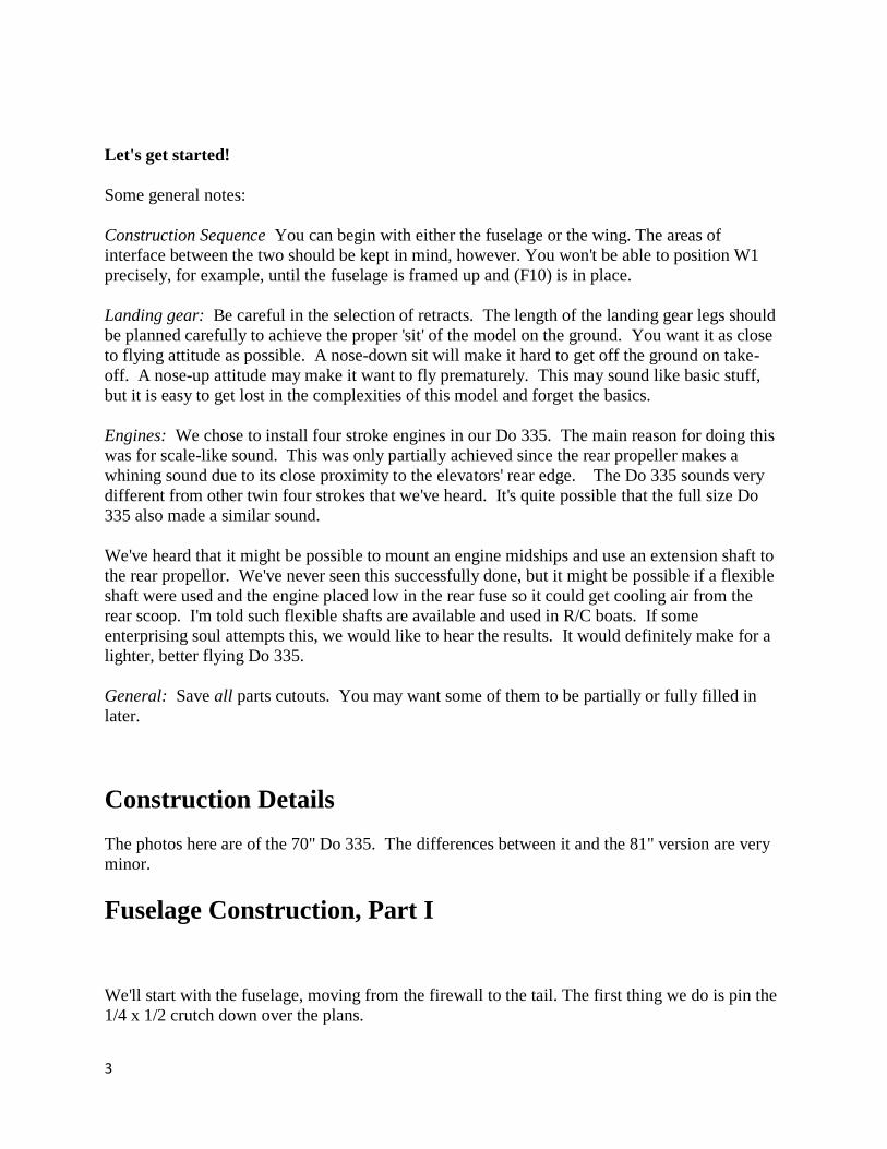
Here is the crutch pinned down, with a few
formers test-fitted on top. The crutch serves
as a guide when placing the formers, it
ensures that the fuselage is built with straight
and true alignment. We will build the top half
of the fuse over the crutch, partially sheet it,
then remove it from the building board.
The Forward Fuselage Hatch
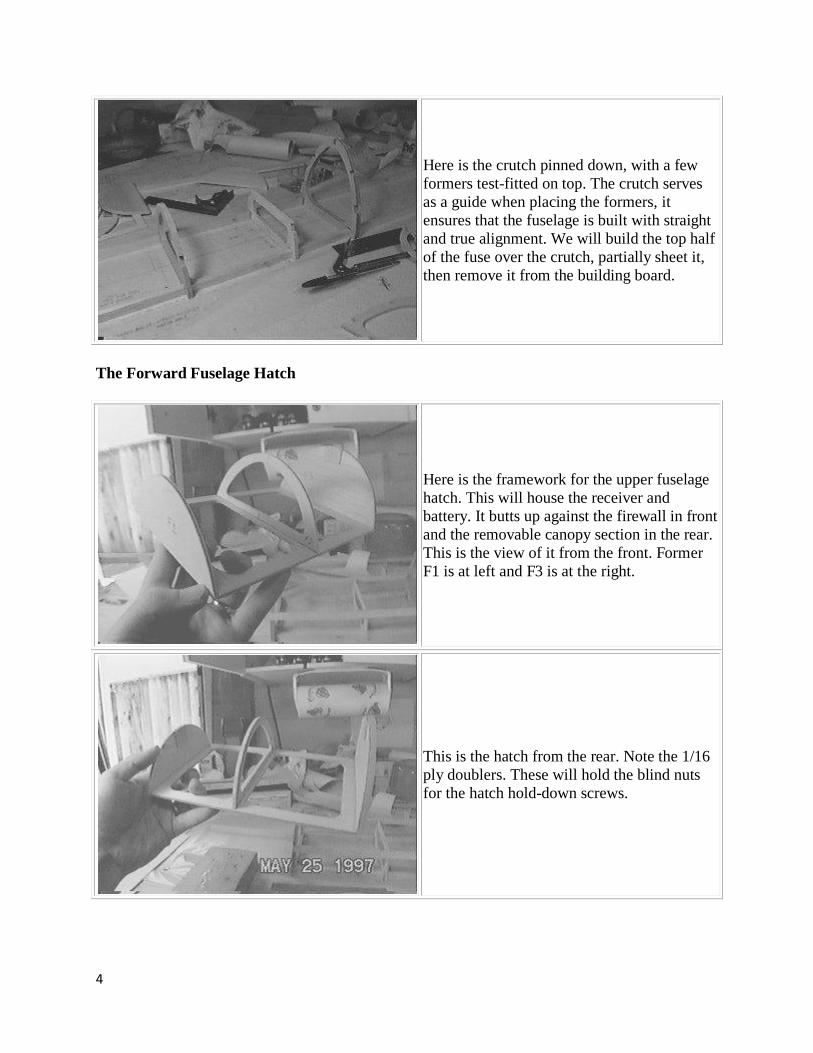
Here is the framework for the upper fuselage
hatch. This will house the receiver and
battery. It butts up against the firewall in front
and the removable canopy section in the rear.
This is the view of it from the front. Former
F1 is at left and F3 is at the right.
This is the hatch from the rear. Note the 1/16
ply doublers. These will hold the blind nuts
for the hatch hold-down screws.

5
Here is the hatch in place on the crutch. All
the upper fuselage formers are now in place,
as are the first two stringers (1/2 x 3/16).
The rear part of the fuselage showing the
formers and stringers.
The rear fuselage. The tail will go between
the last two formers at the right (F19 & F20).
The rear firewall will be glued to the rear of
F20. The 1/16" platform resting on the crutch
(with the three round holes cut into it) is the
rear tank support.

6
The upper fuselage, view from the rear. Now
we're getting somewhere!
We acquired stick and sheet from Superior
Balsa & Hobby Supply. We've had nothing
but good experiences ordering from them.

7
Removable Upper Tail Section
At this point in the project, I visited the Paul E. Garber Facility of the NASM and saw the last
remaining real Do 335 in the world.
The Tail Section
This is the right half of the stab, top-side
facing up. It was framed up on the building
board upside-down, then the bottom was
sheeted. You can see the notch for F19B can
be seen on rib #2. The leading edge and spar
were shimmed up from the building board to
get the proper rib position.
The finished upper-tail center section. The
three sections of rib #1 are glued directly to
the 1/16" ply plate, and to the upper tail post
and F19B.
8
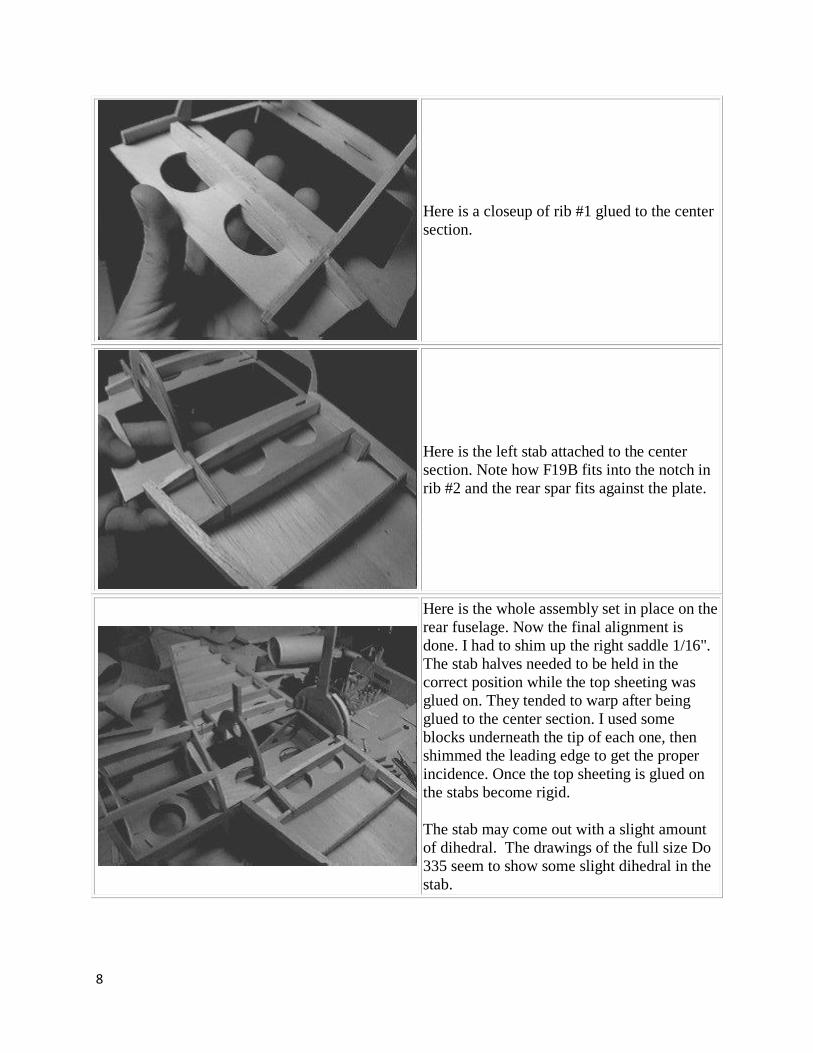
Here is a closeup of rib #1 glued to the center
section.
Here is the left stab attached to the center
section. Note how F19B fits into the notch in
rib #2 and the rear spar fits against the plate.
Here is the whole assembly set in place on the
rear fuselage. Now the final alignment is
done. I had to shim up the right saddle 1/16".
The stab halves needed to be held in the
correct position while the top sheeting was
glued on. They tended to warp after being
glued to the center section. I used some
blocks underneath the tip of each one, then
shimmed the leading edge to get the proper
incidence. Once the top sheeting is glued on
the stabs become rigid.
The stab may come out with a slight amount
of dihedral. The drawings of the full size Do
335 seem to show some slight dihedral in the
stab.

9
The assembly viewed from the rear. You can
see how the rear spar, the upper fin post, and
the rear stab spar fit together here. Actually,
the rear spar and side-tab of the fin post did
not quite come together. I put a piece of 1/20"
balsa in between to fill the gap.
Now the stab is sheeted and the fin
construction is underway. The 1/8" sheeting
on the curved fuselage-part is also glued in
place.
The tail assembly from the rear. Note that the
sheeting is not glued to F20, which is the rear
fuse former visible in this view. The aft
firewall will be glued directly to F20 after the
fuse is removed from the building board.

10
Fuselage, Part II
It's starting to look like an airplane now. We decided to use four strokes in our Do 335. For
those of you who have never heard twin four strokes in flight, let me tell you, it is a religious
experience! The first time for us was when a club member built a P-38 powered by two OS .46
Surpass engines. The sound that thing made on a low pass, it was enough to make your heart skip
a beat! We chose to put a Saito .90 in the nose and a Saito .50 in the tail.
FOUR STROKES!!!
The Saito .50 mounted on our testbed plane, a
US Aircore .40. We broke it in that way,
flying it in the same orientation it will be
mounted in the Do 335. Concerns about
whether it would need on-board glow turned
out to be unfounded. It ran fine as-is.
This is the rear firewall, modified to accept
the Saito .50. One thing is clear, the plane
will be heavier! The engines are heavier, the
supporting structures are heavier, and some
workarounds will also cause extra weight.

11
The modified tail section, with a hole cut into
F20 to accept the backset firewall, which
*just* fits between the firewall braces. Note
the protruding ends of the crutch.
The new firewall in place. Notice that alot of
F20 and the left firewall brace will have to be
cut away. We were a bit concerned about this
but it turned out OK.
The rear cowl in place. Trimming and fitting
it turned out to be pretty easy.

12
The Tail Section is Finished
The completed tail section with rear cowl in
place.
The tail section from the rear. It's starting to
look like something!

13
The Fuselage Comes off the Building Board
With the 1/8" sheeting in place on the upper
fuse, it can be removed from the building
board. Once off the building board, the 1/16"
ply lower stiffners are glued into the slots
between the formers and the crutch. The
lower formers will now be glued over these
frames. The forward firewall is just
temporarily set in place, I haven't glued it yet.
It will have to have a backset firewall like the
rear engine to accept the Saito .90.
A better view of the 1/16" ply stiffners.
Here's a view we couldn't see before - the
bottom of the upper fuselage.
14
Fuselage, Part III
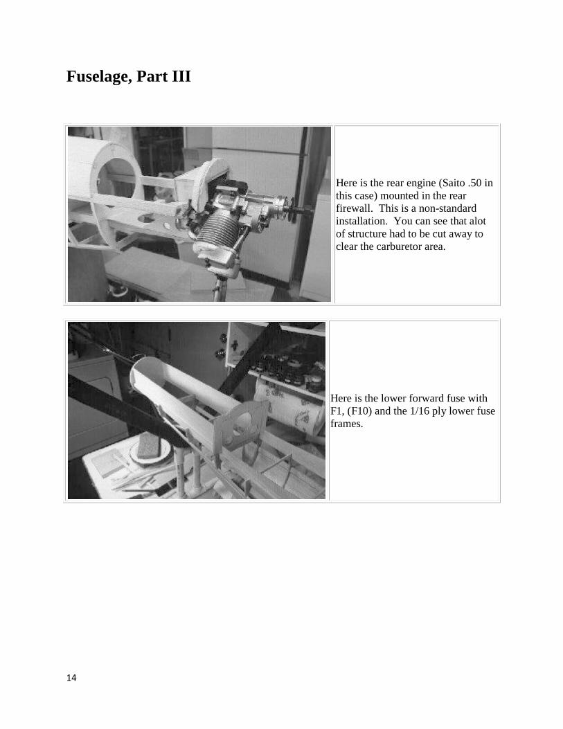
Here is the rear engine (Saito .50 in
this case) mounted in the rear
firewall. This is a non-standard
installation. You can see that alot
of structure had to be cut away to
clear the carburetor area.
Here is the lower forward fuse with
F1, (F10) and the 1/16 ply lower fuse
frames.

15
Here is the same area with (F4) and
(F8) installed. The former numbers
with parenthesis, by the way, are the
lower halves of these formers, so for
example, F4 is the upper part, (F4)
is the lower part below the crutch.
Note also in this picture the
mounting blocks for the throttle
servo.
Upper front fuselage. Note the .010
styrene sheet plastic on the rear
cockpit bulkhead. I'm using this in
the cockpit area to prevent having to
fill the woodgrain when finishing
this area.
Note also here the completed front
hatch. It is held on with two 4-40
screws front and back.
Overall view of the fuse with both
engines mounted.

16
Close-up of the lower rear fuse with
all lower formers and stringers in
place. It's best not to go much
further with this area until the wing
is ready for mounting.
Shown here is an optional scale-
type hinge, as apposed to the more
standard bevel type called for in the
plans. It achieves a much better
look and scale operation. It really
isn't all that much work either.
Robart hinge-points are used
throughout.

17
Nosegear Installation
Here's the forward fuse with nosegear
installed.
Used here is a Robart 640 series steerable
nosegear unit with a 7/16" diameter forked
strut. The nosegear retracts through an angle
of 105 degrees, which is 10 degrees less than
the scale retraction angle of 110 degrees. I
special ordered it from Robart and it took
forever for them to get it to me (about 8
weeks) but I'm very pleased with the product.
We also used 640 series retracts for the
mains, 85 degree, straight struts.
Here is the nosegear well. You can see the
steering arms and air cylinder. The nosegear
doors are attached with 4 Klett hinges. A
piece of music wire is pushed through all 4
hinges, making for a nice crisp action.
Here is a closeup of the door actuation
mechanism from the front. F10 is visible in
the background.
I had to rework the actuators, the ones on the
plans were too short to catch the strut on the
way down. Note the rubber bands that hold
the doors in the open position.
In the background you can see the pull-pull
cables for nosegear steering. The servo is not
mounted in this view so the cables are slack.

18
Here are the actuators from the back. The
retract unit can be seen in the background.
Closeup of the nosegear unit. Note that I am
mounting them with 8-32 nylon bolts (only
two of them are installed in this picture). The
idea is for the bolts to fail before the nosegear
or it's mounting structure get destroyed.
Nosegear retraction sequence - #1

19
retraction - #2
retraction - #3
retraction - #4

20
Canopy and Cockpit Area, Rear Engine
The canopy frame is made up with 3/32"
plywood. I left about 1/16" thickness to
allow for the plastic that will be glued over
the frame. It wasn't easy to find a glue that
sticks well to both acrylic or buterate plastic
and wood. Epoxy doesn't stick to the plastic.
Plastic glue doesn't stick well to wood. We
finally found Ambroid glue which does the
trick. This stuff has been around since the
early 1900's. It's great stuff, try it!
Note the paper instrument panel. This was
created by scanning a photo of the real
instrument panel and drawing over the image
with a CAD program. The resulting drawing
was then scaled to the proper size and
printed. This was used as a pattern to make
the instrument panel from sheet plastic.
The canopy in the open position. Dollhouse
hinges (brass) are used for hinging. The
canopy was secured with eyeglass screws
through the canopy sill, accessed through the
vent hole in the canopy.

21
Here are a few shots of the tail section. The
spinner in this case is from Tru-Turn. They
made the only 3-1/4" spinner in the proper
shape. They did a special cutout for the
pusher prop - this cost about $15 extra.
The tail section from below left. The spinner
is a bit short of scale length, but it is close
enough for "sport-scale." Note close
proximity of elevator and engine head.
Close-up of carburetor area. Note the throttle
arm right next to the stab skin near the hinge
line. The throttle linkage runs right through
this part of the 1/4" x 1/2" stab "sill", which is
braced against the triangular rear firewall
brace. This brace can be seen in this photo, it
is the piece with two round holes cut into it.
Much of this had to be cut away to clear the
carburetor and rear engine.

22
Tail section. Rudder and elevators at
maximum deflection. The rudder is driven by
a steering shaft that runs down next to the
firewall, between the engine mount and the
carburetor, and down to the lower rudder.
This shaft is bent at 90 degrees on top, and
fits into a slot in the lower rudder. This
allows the entire stab-fin assembly to be
removable.
The upper forward fuselage with hatches and
canopy removed. The canopy area is lined
with .010 sheet plastic, so it can be painted
without having to fill the woodgrain.
Lower fuselage hatch in the open position. It
is held on by one screw in the front and 2
screws in the back. The reason for two
screws in the rear is that a centered screw
would not be accessible because of the
nosegear strut.
Note the frame for holding the retract valve.
The retract servo will be mounted just
forward of the valve, you may be able to just
see the outline of the servo drawn on the
wood.
23
Wing Construction, Part I
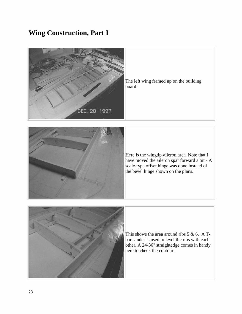
The left wing framed up on the building
board.
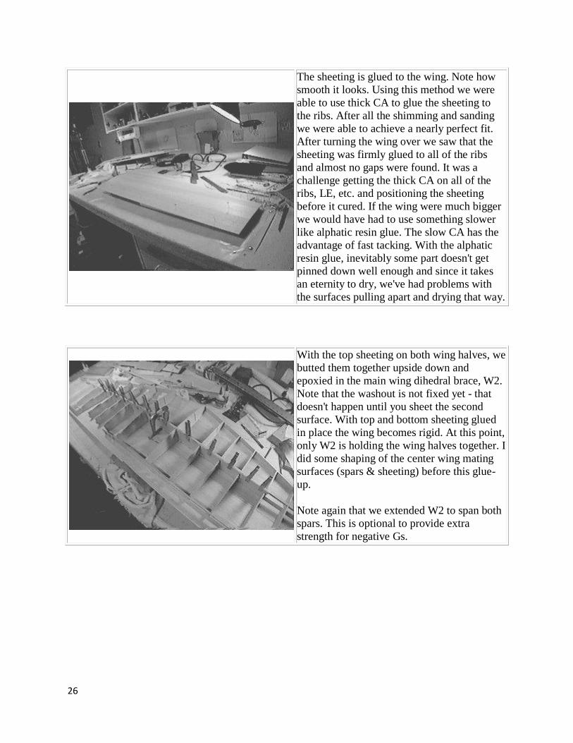
Here is the wingtip-aileron area. Note that I
have moved the aileron spar forward a bit - A
scale-type offset hinge was done instead of
the bevel hinge shown on the plans.
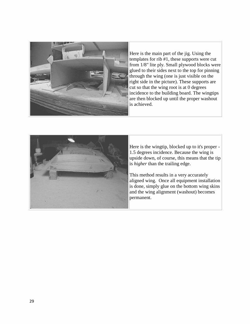
This shows the area around ribs 5 & 6. A T-
bar sander is used to level the ribs with each
other. A 24-36" straightedge comes in handy
here to check the contour.

24
Cutting a cross-grain shim. This is a good
method for shimming up ribs and formers to
make a smooth contour. This shouldn't be
necessary in too many places. After these are
glued on I use a 24" or 36" steel ruler across
the formers or ribs to check the contour.
A shim cut from 1/8" balsa. Even though this
is 1/8" thick, it bends quite easily without
breaking. A little thick CA glue and you can
instantly make a rib or former 1/8" bigger.
The shim can be trimmed and sanded very
easily.
We elected to enlarge the main dihedral brace
(W2) to span both upper and lower spars.
This is probably not necessary, but we were
concerned about the strength of the wing
when subjected to negative Gs.
In this picture you can see the temporary
square 1/8" balsa braces glued over the gaps
in the ribs where the plywood dihedral brace
(W2) will glue in. This keeps the ribs in form.
They will be cut through before W2 goes in.

25
Wing Construction, Part II
Here we glue up sheeting for the wings. The
process begins by selecting 3" wide pieces
that fit reasonably well. They don't have to fit
perfectly for this method. There should be no
large gaps when you push the pieces together,
however. Once you've decided which two
pieces to glue together, cut a long piece of
cellophane packing tape, 2" or so longer than
the balsa planks. (note the tape roller in the
lower center of the picture) Lay the tape
sticky side up on the table between the planks.
Lay the first plank on the tape, covering half
of the tape and leaving the other half exposed.
Now starting from one end, butt the two
planks together sticking the second piece to
the tape, pushing them together as you go. A
firm, hard surface is best for this.
Once both pieces are stuck to the tape, pick them up, open the joint and use thick CA to glue the
seam. Wipe the excess and use accelerator to speed the process. Flip the pieces over, remove the
tape, and use more accelerator on this side. The side with the tape will be the "good" side that
will be on the finish side of the model. The tape keeps the planks flush, and a large sheet can be
made this way that will have no "steps" in it where the seams aren't quite flush. If you hold this
sheet up to the light it might appear to be a single piece except for the different coloration of the
wood! This makes sanding and finishing much easier later. Some guys sand this sheeting
assembly before gluing it to the model, I didn't find this to be necessary. It came out so smooth I
don't think much sanding will be necessary.
26
The sheeting is glued to the wing. Note how
smooth it looks. Using this method we were
able to use thick CA to glue the sheeting to
the ribs. After all the shimming and sanding
we were able to achieve a nearly perfect fit.
After turning the wing over we saw that the
sheeting was firmly glued to all of the ribs
and almost no gaps were found. It was a
challenge getting the thick CA on all of the
ribs, LE, etc. and positioning the sheeting
before it cured. If the wing were much bigger
we would have had to use something slower
like alphatic resin glue. The slow CA has the
advantage of fast tacking. With the alphatic
resin glue, inevitably some part doesn't get
pinned down well enough and since it takes
an eternity to dry, we've had problems with
the surfaces pulling apart and drying that way.
With the top sheeting on both wing halves, we
butted them together upside down and
epoxied in the main wing dihedral brace, W2.
Note that the washout is not fixed yet - that
doesn't happen until you sheet the second
surface. With top and bottom sheeting glued
in place the wing becomes rigid. At this point,
only W2 is holding the wing halves together. I
did some shaping of the center wing mating
surfaces (spars & sheeting) before this glue-
up.
Note again that we extended W2 to span both
spars. This is optional to provide extra
strength for negative Gs.

27
The dihedral brace W2 clamped in place. 30
minute epoxy was used, as we always do
when joining birch ply to balsa in high stress
areas. Note the 3/32 plates that held the ribs
together before W2 was in place. We sawed
through them and then slid W2 into the slot.
Note the small shims between the lower part
of the ribs and W2. These were used just to
put more pressure against W2 on the bottom
since we couldn't clamp down there.
Another view of the W2 glue-up. We couldn't
clamp W2 to the upper spar, but we found that
the rear ribs (with shims) applied enough
pressure to keep W2 firmly against it.
This is an exciting step, because the wing
finally begins to take shape!
The wing center section with W1, W2, & W3
now glued in place. Mind carefully the
installation of W1. It *must* mate exactly with (F10). The wing hold-down dowels go
through there. The 81" version even has
oversize slots in Rib #1 to suggest the variable
placement of W1. You will have to wait until
you can mate the wing and fuselage before
gluing in W1.

28
The retract plate support doublers are glued in
place with epoxy. Note also the 1/2" triangle
stock to reinforce the W2/doubler joint. This
is a bit different than the structure called for
on the plans. I used thicker plywood - 1/8" ply
for the doublers and 1/4" ply for the plate.
After seeing too many models with retract
support structure ripped out, or with retracts
damaged through hard landings, We have
arrived at our current thinking. The idea is to
make the fasteners that hold the retracts to the
wing weaker than either the supporting
structure or the retract units. That way in a
hard landing, it is the fasteners that fail and
little else. We use nylon bolts, 8-32 in this
case. We've found these to be very strong in
the past, too strong in fact for our Dynaflite
Spitfire. Its retract rails were ripped out with
8-32 nylon bolts!
This practice was proven out during a hard
landing with the Do 335 at a contest. We
were attempting a "spot" landing (probably a
foolish thing with this plane!) and landed
hard. Two of the four nylon bolts popped,
preventing damage to the structure.
The wing from above, in the building jig. A
fixed jig is the best way to align the wing.
Other methods could be used, of course.
29
Here is the main part of the jig. Using the
templates for rib #1, these supports were cut
from 1/8" lite ply. Small plywood blocks were
glued to their sides next to the top for pinning
through the wing (one is just visible on the
right side in the picture). These supports are
cut so that the wing root is at 0 degrees
incidence to the building board. The wingtips
are then blocked up until the proper washout
is achieved.
Here is the wingtip, blocked up to it's proper -
1.5 degrees incidence. Because the wing is
upside down, of course, this means that the tip
is higher than the trailing edge.
This method results in a very accurately
aligned wing. Once all equipment installation
is done, simply glue on the bottom wing skins
and the wing alignment (washout) becomes
permanent.
30
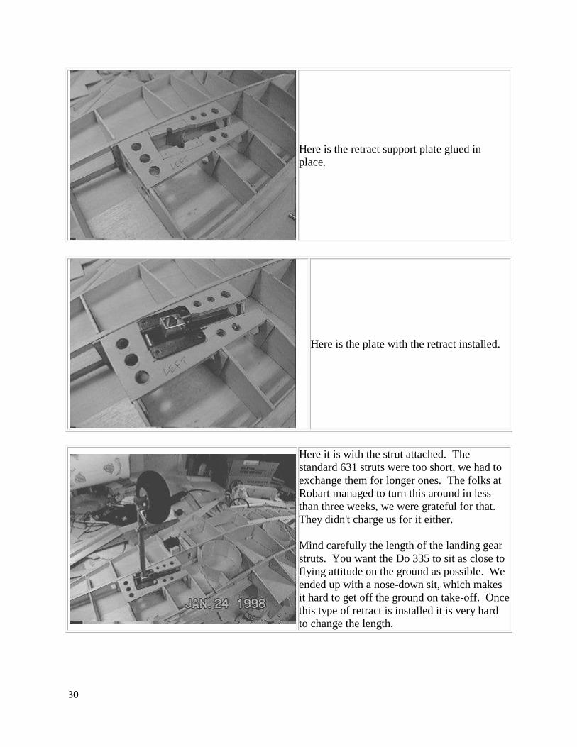
Here is the retract support plate glued in
place.
Here is the plate with the retract installed.
Here it is with the strut attached. The
standard 631 struts were too short, we had to
exchange them for longer ones. The folks at
Robart managed to turn this around in less
than three weeks, we were grateful for that.
They didn't charge us for it either.
Mind carefully the length of the landing gear
struts. You want the Do 335 to sit as close to
flying attitude on the ground as possible. We
ended up with a nose-down sit, which makes
it hard to get off the ground on take-off. Once
this type of retract is installed it is very hard
to change the length.

31
Here the strut is in the retracted position. The
flap control rod clears the strut with room to
spare. We really like the look and feel of the
631 retracts. They look and feel alot more
robust than the music wire retracts we've
owned.
Aileron Construction
Photo #1
After cutting sheeting to the right shape, we
glue the ribs on and sand this half to accept
the other side.

32
Photo #2
Here the aileron is being sanded with the aid
of a T-bar sander to maintain even pressure
across the ribs and trailing edge. Sandpaper is
stuck to a piece of 3/4" plywood with 3M77 for this purpose. When the sandpaper wears
out you can remove it from the plywood with
a Monokote heat gun. The heat releases the
3M77's stickiness.
Photo #3
Here you see the edge-on view of the aileron
after sanding. Note how the trailing edge is
sanded sharp.
Photo #4
Another view of the sanded aileron half. The
sanded edges are just a little rough - perfect
for good glue adhesion.
33
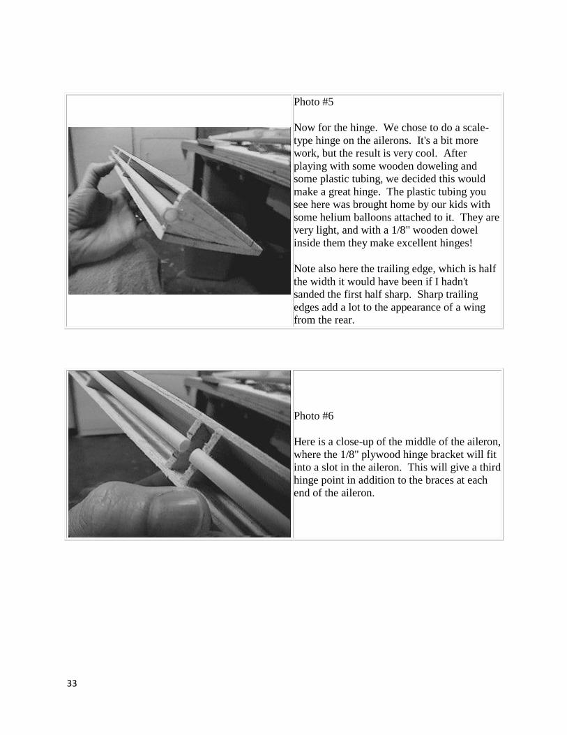
Photo #5
Now for the hinge. We chose to do a scale-
type hinge on the ailerons. It's a bit more
work, but the result is very cool. After
playing with some wooden doweling and
some plastic tubing, we decided this would
make a great hinge. The plastic tubing you
see here was brought home by our kids with
some helium balloons attached to it. They are
very light, and with a 1/8" wooden dowel
inside them they make excellent hinges!
Note also here the trailing edge, which is half
the width it would have been if I hadn't
sanded the first half sharp. Sharp trailing
edges add a lot to the appearance of a wing
from the rear.
Photo #6
Here is a close-up of the middle of the aileron,
where the 1/8" plywood hinge bracket will fit
into a slot in the aileron. This will give a third
hinge point in addition to the braces at each
end of the aileron.

34
Photo #7
Another view of the aileron with plastic tube hinge attached.
Photo #8
Now I've glued two 1/8" strips on either side
of the tube. This presents a flat surface to
which I will glue the leading edge.
Photo #9
Here the 1/2" soft balse leading edge is glued
in place. After this I used a compass to draw
a semicircle centered on the tube for use in
shaping the leading edge.

35
Photo #10
Here the aileron is sanded to final shape.
Photo #11
The finished aileron. Note the slot in the
middle to accept the hinge bracket on rib #7.

36
Photo #12
Here is a close-up of the aileron slot. This is the external view of what you see in Photo #6.
Photo #13
Here you can see the three plywood hinge
braces attached to the wing. The inboard
brace acts as a brace for the flap hinge dowel
as well.
Photo #14
Here is the dowel going through the wingtip
hinge brace.

37
Photo #14
Here is another view of the wingtip, with the
aileron now in place.
Photo #16
The completed aileron mounted on the wing.

38
Photo #17
Here is a close-up of the 1/8" hinge brace, glued to rib #7.
Flap Construction
Photo #1
The flap is constructed in much the same way
as the aileron, except the leading edge radius
is larger, so you can bend a piece of 3/32"
sheeting to form the leading edge. Al
Master's suggestion of wrapping the wetted
sheeting around a broomstick worked well,
although I ended up cutting this piece a bit
short before forming it.

39
Photo #2
Here is a close-up of the flap leading edge.
Note the two extra formers spaced closely
together. These are the supports for the
formica control horn that I will glue in later
after finish sanding, but before painting.
Photo #3
This is the flap hinge dowel support piece. It is made from 5/32" balsa and a small piece of
1/4" plywood in the middle. The dowel will
be secured to the plywood with screws.
Photo #4
Here the two inboard flap hinge dowel
supports are glued in place. Holes will be cut
in the top sheeting to make this area
accessible. The dowels have to be pulled out
all the way to get the flap loose and remove
it. You could mount the flaps permanently of
course, but it is nice to have things
serviceable. It also makes finishing &
painting a bit easier.

40
Photo #5
Here is the outboard (right-hand) flap hinge
dowel support piece glued in place between
ribs 5 & 6. Access to this dowel is through
the aileron spar. The ailerons have to be
removed first, of course.
Photo #6
Here is the slot in the aileron spar to access
the dowel. The wingtip is to the right in this
picture. The flap will go to the left.

41
Photo #7
Here is a view of the wing center section,
right before the bottom sheeting is applied. In
the lower part of the picture you can see the
flap hinge supports.
In the middle section you can see the 1/4" ply
wing bolt plate, secured with 3/4" triangle
stock glued against the #1 ribs. Here you can
also see the short sections of 1/2" triangle
stock glued against the top sheeting. This is
for sheeting support where the wing saddle of
the fuselage rests.
In the forward section you can see W1 braced
with triangle stock, the air tank for the main
landing gear, and the square plastic tube
conduits for the flap and aileron servo wires.
Photo #8
Here is the flap servo, mounted to a 1/8" lite
ply plate with two pine blocks to hold the
screws. This assembly gets flipped over and
installed face down into the bottom of the
wing.

42
Photo #9
Now you can see the flap servo plate mounted
on 1/4" hardwood rails in between ribs 2 & 3.
The pushrod goes through a hole in the spar
and will exit the skin near the flap leading
edge.
Photo #10
Close-up of the square plastic tubing used as a
conduit for the servo wires.
Photo #11
Close-up of the flap pushrod. We used all 4-
40 hardware.

43
Wing/Fuselage Mating
Photo #1
A historic moment! The wing meets the fuse
for the first time. The fit looks good!
Photo #2
Same assembly from a different angle.

44
Photo #3
This is what it's all about! She's finally starting to look like an airplane!!!
Photo #4
Another view.
Photo #5
Note the block under the nosewheel. The
strut lengths are a bit out of whack. I chose to
shorten the mains, mainly because the
nosewheel installation is more critical with
the closing doors and all.

45
Photo #6
She looks almost ready for a sortie!
Lower Fin & Rear Fuse
Photo #1
The basic framework of the lower fin. The
leading edge is 3/8 x 1/2, the spar is 1/8" ply.
We had to move the spar forward because of
the scale hinge style we chose.
We debated whether to make the lower fin
removable. We were afraid of what would
happen in the event of a gear-up landing. We
decided in the end that the structure would
probably survive it, especially if I reinforced
it just a bit, without adding too much weight.
I was also afraid of a removable unit
separating in flight.

46
Photo #2
The plans showed the leading edge extending
only just below the lower skin. We decided
that for just an ounce or two I could extend it
down to F19, which would make it much
stronger. Note the added piece of 1/8" lite ply behind F19. This was needed because of the
hole in F19. Note also just below this the
hole in the tank support for access to the tail
hold-down screw. The 81" version uses a
different tail hold-down arrangement.
Photo #3
The plans showed the lower fin spar butting
up against F20. Since it had to be moved forward for the scale hinge, it no longer rests
against F20. I therefore reinforced it with
1/8" lite ply gussets. These gussets are glued
to the crutch pieces.
Photo #4
Here is a plan view of the framework. You
can see the gap between the spar & F20.

47
Photo #5
The fin ribs are added. These are just
rectangular pieces of 3/32" balsa. We
"upgraded" the sheeting here from 1/16" to
3/32" to make a slightly stronger structure.
The plans called for 1/16" ribs and sheeting.
Note also here the fuse bottom pieces that go
around the root of the fin. These are 5/16"
hard balsa for strength. These pieces will be
hollowed out later for lightness. Weight in
the tail is critical! Every extra ounce here will
mean 2 oz. of lead in the nose.
Photo #6
The fin framework after sanding. Note the
airfoil shape and the thinness of the tip! The
bottom is left as a separate piece
intentionally. On the real Do 335, this piece
was a spring-loaded, shock-absorbing skid!
Because it fit up inside the fin, there is a break
in the outline.

48
Photo #7
Edge-on view of the fin framework.
Photo #8
Rear view of fin framwork. Note taper.
Photo #9
The lower fin is sheeted with soft 3/32" balsa.
In preparation for applying the rear fuse
sheeting, all pushrods are routed to their final
locations. Clearances are checked. Note the
white plastic tubing at left next to F19. This
is the access hole for the forward tail hold-
down screw. An 8-32 nylon bolt will be used
(they're very light and strong).

49
Photo #10
Close-up of the rear fuse before sheeting. At
the bottom of the picture is the rudder pushrod. In the upper part of the picture, the
white pushrod that goes through the middle of
the engine cutout is for the left elevator.
Harder to see is the red throttle pushrod, it has
the masking tape tag labeled "rear" on it.
Wings, Part III
Photo #1
The wingtip frame from the plans follows the
outline of the wingtip and is about 1" wide.
In other words there is a large cutout next to
the tip rib W9. We cut this part per the plans,
but did not follow the plan suggestion of
using simple triangle bracing on top and
bottom and sheeting over with 3/32" balsa.
For one thing this looked very weak to us, and
it also didn't have a nice smooth contour. We
often like to pick up our airplanes (with a
partner) by the wingtips, so we didn't want
this area to be flimsy. So we used very soft,
light 1/2" balsa sandwiched on both sides.
Yes, this will add a few ounces, but this isn't a
glider!!!
50
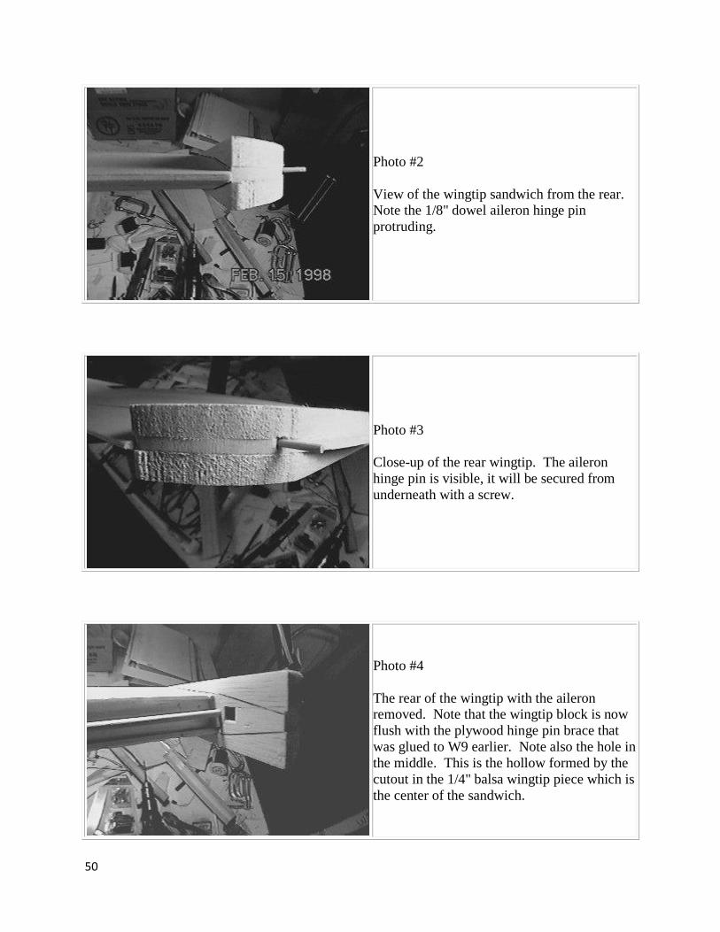
Photo #2
View of the wingtip sandwich from the rear. Note the 1/8" dowel aileron hinge pin
protruding.
Photo #3
Close-up of the rear wingtip. The aileron
hinge pin is visible, it will be secured from
underneath with a screw.
Photo #4
The rear of the wingtip with the aileron removed. Note that the wingtip block is now
flush with the plywood hinge pin brace that
was glued to W9 earlier. Note also the hole in
the middle. This is the hollow formed by the
cutout in the 1/4" balsa wingtip piece which is
the center of the sandwich.

51
Photo #5
High-angle view of the wingtip block.
Photo #6
The wing with all the pieces in place for the
first time!

52
Photo #7
The center section is glassed.
Photo #8
Edge-on view of the wing trailing edge.
53
Wing/Fuselage Joint, Part II
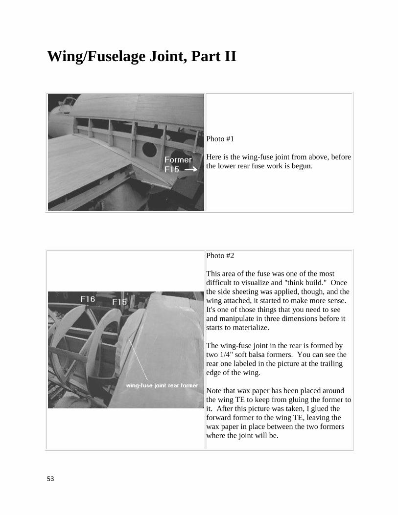
Photo #1
Here is the wing-fuse joint from above, before
the lower rear fuse work is begun.
Photo #2
This area of the fuse was one of the most
difficult to visualize and "think build." Once
the side sheeting was applied, though, and the
wing attached, it started to make more sense.
It's one of those things that you need to see
and manipulate in three dimensions before it
starts to materialize.
The wing-fuse joint in the rear is formed by
two 1/4" soft balsa formers. You can see the
rear one labeled in the picture at the trailing
edge of the wing.
Note that wax paper has been placed around
the wing TE to keep from gluing the former to
it. After this picture was taken, I glued the
forward former to the wing TE, leaving the
wax paper in place between the two formers
where the joint will be.

54
Photo #3
Using a T-bar, We sanded the two wing-fuse
joint formers to the contour formed by the two
fuse formers behind them, F15 & F16. The
wing was then removed and sheeting was
applied. See the result below.
Photo #4
We start by cutting the air scoop cross-section
using the template from the plans. This is
from 1/8" lite ply. This piece will hold the
dowels which will hold the whole assembly to
the fuse. A 6-32 nylon bolt will hold the
rear.
Making this lower air scoop removable costs
almost nothing in terms of weight, but adds
alot in servicability. I'm actually looking
forward to servicing this airplane! Every area
of the fuse containing components that will
need service is easily accessible.
I've cursed over too many airplanes that had
no removable hatches - and components
requiring service buried deep within
structures with limited access. It's just not
worth it!!!

55
Photo #5
Close-up of the lite ply template and side
blocks. Soft 1/2" balsa is used for the blocks. Inside the block on the right you can just see a
smaller inner block that was needed to fill in
the hole in the inner cove next to the skin.
Photo #6
All side blocks have been added. You can
clearly see the inner cove filler blocks in this
view.
Photo #7
The bottom blocks are added. Thick CA is
used throughout. The blocks are tack-glued to
the fuse with a couple of small drops of thick
CA.

56
Photo #8
The main part of the scoop is carved and
sanded to rough shape.
Photo #9
The forward part of the air scoop is made
from an open-ended "box" of 1/2" balsa. The
front face is made from 1/16" ply.
57
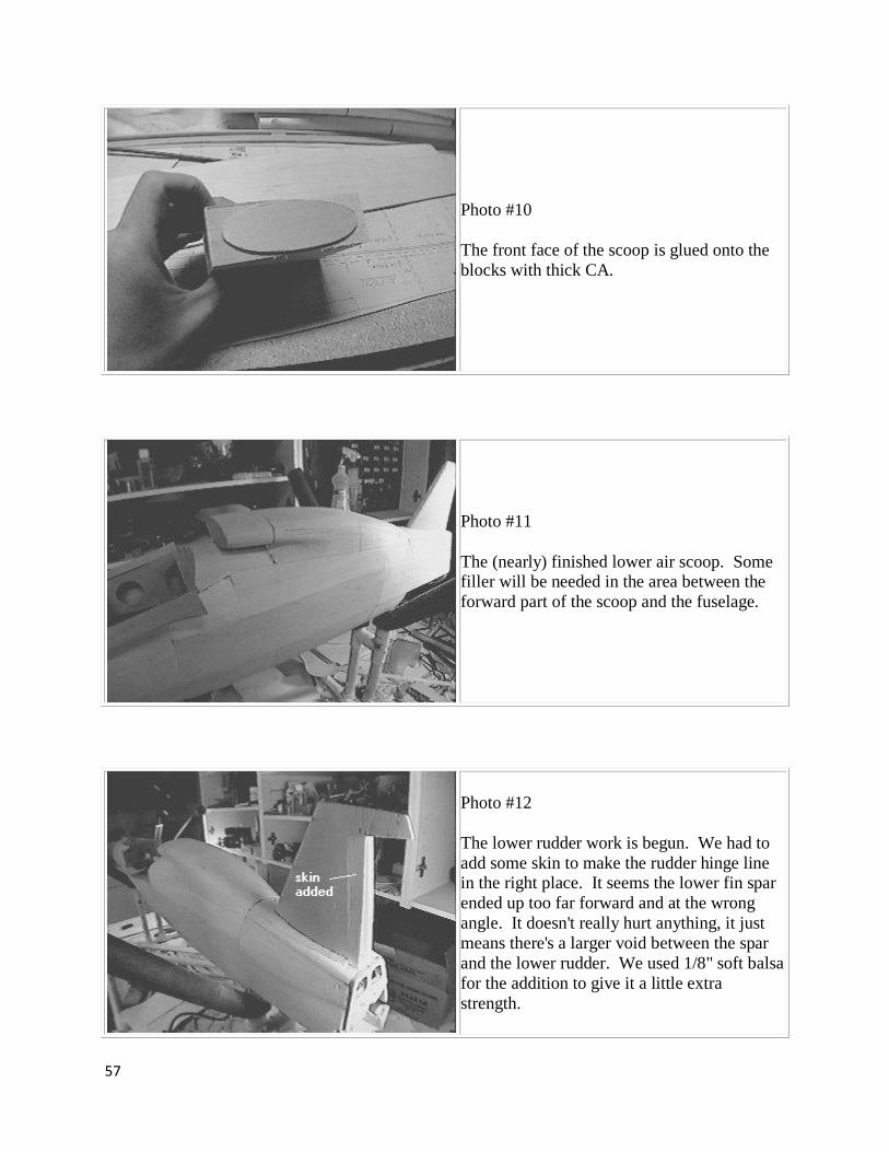
Photo #10
The front face of the scoop is glued onto the
blocks with thick CA.
Photo #11
The (nearly) finished lower air scoop. Some filler will be needed in the area between the
forward part of the scoop and the fuselage.
Photo #12
The lower rudder work is begun. We had to
add some skin to make the rudder hinge line in the right place. It seems the lower fin spar
ended up too far forward and at the wrong
angle. It doesn't really hurt anything, it just
means there's a larger void between the spar
and the lower rudder. We used 1/8" soft balsa
for the addition to give it a little extra
strength.

58
Photo #13
This is the lower end of the 3/32" music wire
torque rod that connects the upper and lower
rudder halves. It (happily) goes through the
engine area just between the mount and the
rear of the engine.
I filed flats on both sides of the lower end,
which will fit into a flattened piece of brass
tubing glued into the rudder.
Many different arrangements are possible for
driving the lower rudder.
Photo #14
Here is the flattened brass tubing. The lower
part is cut and spread open to provide
additional leverage once this is glued into a
balsa block in the lower rudder.

59
Photo #15
Here is the wire fitted inside the flattened
tubing. This is the lightest linkage I could
think of that would be sufficiently robust. The lower end of the music wire had to fit
through the 3/32 hole, so I couldn't solder
anthing to it directly.
Photo #16
Sneak peek! Here is the foward cowling
framework. This is the first thing we
designed and built using a CAD program. We
used AutoCAD on our Sun workstation. The
result? Faster design and *perfect* parts fit.
My local blueprint shop will plot my creations
for 80 cents per square foot.
I've since used TurboCAD on the PC with
great success.
We had a fiberglass forward cowl from Al
Masters, but we decided to build up a cowling
for a number of reasons. For one thing, we
knew for sure that we would need weight in
the nose. So why not build a robust cowl that
will easily handle some lead? Less lead will
be required if it is mounted in the front cowl
ring, and a stronger structure is required if this
weight is to be prevented from ripping the
cowling off during landing! Don't laugh,
we've seen this happen!

60
Photo #17
Here is the finished rear fuse. Looking good!
Front Cowl & Wing Fairings
Photo #1
The cowl framework (as seen in the last
installment) has now had 1/32 ply epoxied to
the forward part. The plywood was soaked in
water and wrapped around a quart paint can to
establish the "curl" before gluing it on.
The circular piece of 1/16" ply in the
foreground will serve as the backplate for the
forward cowl ring, which will be built up
from the segments stacked behind it. These
were cut using a paper template on the scroll
saw and sanded to shape on the bench sander.
61
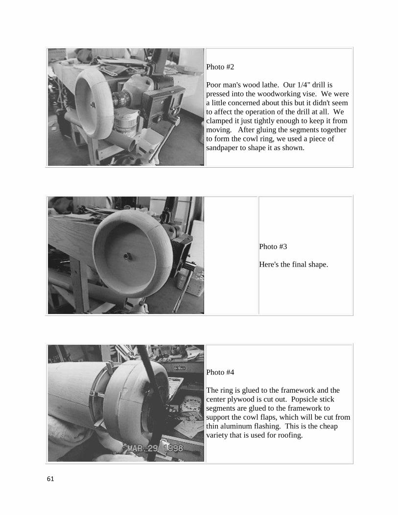
Photo #2
Poor man's wood lathe. Our 1/4" drill is
pressed into the woodworking vise. We were
a little concerned about this but it didn't seem
to affect the operation of the drill at all. We
clamped it just tightly enough to keep it from
moving. After gluing the segments together
to form the cowl ring, we used a piece of
sandpaper to shape it as shown.
Photo #3
Here's the final shape.
Photo #4
The ring is glued to the framework and the
center plywood is cut out. Popsicle stick
segments are glued to the framework to
support the cowl flaps, which will be cut from
thin aluminum flashing. This is the cheap
variety that is used for roofing.

62
Photo #5
The lower part of the cowling showing the
engine cutout and muffler.
Photo #6
The front part of the wing-fuse joint. See the
rear part below. This is just a strip of 3/32
sheet, sanded thin at the edges and glued to
the formers you saw earlier. There is no
former in the center, in fact it is nearly flat at
the center joint.
All filler and fairings are from West Systems
Epoxy with their microlight filler powder.

63
Photo #7
The wing hold-down bolt access holes are
lined with sections of the hard cardboard
tubing that K&S packages and sells their
music wire in.
Photo #8
Lightweight white water-based filler paste is
used on the wing root and removable lower
air scoop.
Photo #9
The front part of the wing-fuse joint. Note the
sharp leading edge. This is a strip on the wing root LE that breaks up airflow at high
angle of attack, causing the wing root to stall
before the rest of the wing. The people I've
talked to that have flown this model say that it
works very well. In combination with the
washout, it makes it hard to break the plane
into full stall. It just "mushes" at low speed.

64
Photo #10
Looking foward at the wing-fuse joint and
former (F10). This fairing was formed by
making a wedge out of 1/2" balsa and butting
the flat side of this wedge against the wing
root (W1) while gluing it to the fuselage.
Epoxy w/microballoons was used to form the
rest of the fairing from the wing spar
forward. All fairings aft of the spar are made
with lightweight white water-based filler to
save weight.
Photo #11
Close-up of wing root leading edge and rib
W1. One of the wing hold-down dowels is
just visible at top.

65
Finishing
We use 1/2 oz glass cloth with epoxy resin thinned 20% or so with denatured alcohol. The
thinned resin goes on like water and soaks in -- no sanding required. I apply a coat of 'slurried'
primer over this, primer mixed with microballoons. This mostly fills the weave of the cloth. Over
that I use automotive primer from a spray can.
This finish is time consuming, but you end up with a hard, durable finish that will never wrinkle,
sag or peel. I can leave the plane in direct sunlight on the hottest day without worry. Dings and
minor damage can be repaired and repainted and the plane looks like new -- without recovering
the whole thing. It's worth the extra time in my opinion.
Painted on markings are a fair amount of work, but well worth it in our opinion. They will never
peel off, sag, wrinkle, or anything else undesireable. You can wipe and clean the model as much
as you like and the markings will be totally unaffected.
Here is one method for painted on markings. You start with drawings or printouts of the
markings. We used CAD printouts scaled to size. You then glue those templates to Frisket paper
with 3M77 spray adhesive. We supply such printouts with the 81" short kit.
Frisket paper is available in most art supply stores. It is a low tack film that comes in sheets and
rolls. With the template glued to the Frisket, you cut around the template with a hobby knife,
cutting through the Frisket film. When this is done, you have a sticky-backed template in the
shape of the marking.
After spraying the marking color (black in the case of the VG PH markings in the photo below,
or white in the case of the fuselage cross) you remove the backing from the Frisket film and
apply the template over the painted surface. Once all of the markings are done in this way, you
can apply the camouflage colors.

66
You can see the swastika and "102" templates (barely) in place on the vertical tail. The red color
is from automotive spot putty, which we use to fill larger dings and holes. It dries very fast and is
very lightweight.
The Frisket is low-tack, and so comes off rather easily. For this reason I would recommend doing
this part as the very last step before painting. Any handling after this is likely to dislodge the
Frisket paper templates. Standard rules about spraying lighter colors first especially apply here.
Black is very hard to cover with white, for example. Watch for
Finishing, Part II
Photo #1
Overall view. Enamels for plastic models were
used:
Testor's Model Master - RLM 80 Olivgruen
(olive green)
Floquil 303033 Medium Green (-34138) - RLM
83 Lichtgruen (light green)
Testor's Model Master - RLM 76 Lichtblau (light
blue) The RLM 83 color is a fairly light green.
The photos on the main page of the building
guide reproduce the colors more effectively.
Accurate colors and markings add alot to the
look of a scale model and are worth the time and
effort. Take it!
67
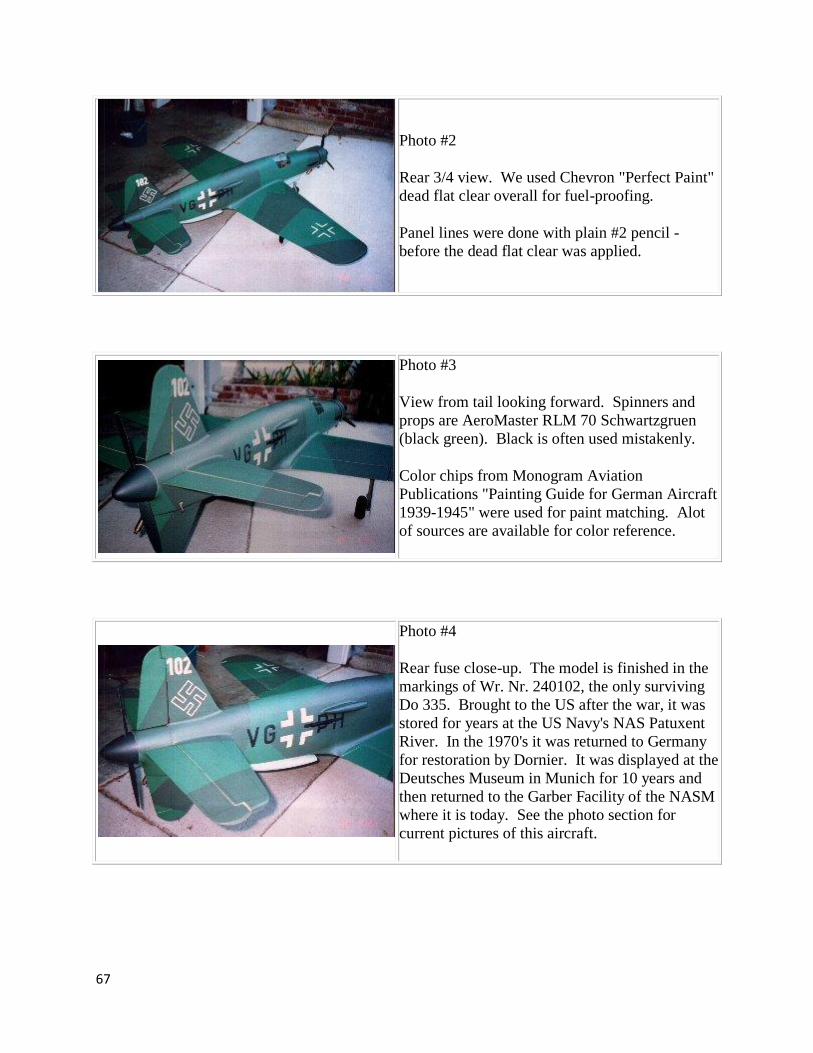
Photo #2
Rear 3/4 view. We used Chevron "Perfect Paint"
dead flat clear overall for fuel-proofing.
Panel lines were done with plain #2 pencil -
before the dead flat clear was applied.
Photo #3
View from tail looking forward. Spinners and
props are AeroMaster RLM 70 Schwartzgruen
(black green). Black is often used mistakenly.
Color chips from Monogram Aviation
Publications "Painting Guide for German Aircraft
1939-1945" were used for paint matching. Alot
of sources are available for color reference.
Photo #4
Rear fuse close-up. The model is finished in the
markings of Wr. Nr. 240102, the only surviving
Do 335. Brought to the US after the war, it was
stored for years at the US Navy's NAS Patuxent
River. In the 1970's it was returned to Germany
for restoration by Dornier. It was displayed at the
Deutsches Museum in Munich for 10 years and
then returned to the Garber Facility of the NASM
where it is today. See the photo section for
current pictures of this aircraft.

68
Photo #5
Nose section close-up. Spinner is Pica's FW-190
spinner. Prop is 3-blade Master Airscrew 13-6.
Cannon blast tubes are made from styrene plastic
tubing (Plasti-struct), shoved into holes carved
out of the balsa skin. Epoxy & microballoons
was used to fill in around the tubes, then the tops
were cut open and then ends shaped.
Supercharger air intakes are from balsa block,
carved and sanded, then hollowed out. Music
wire bent into a circle is used to reinforce the
circular opening. The forward intake is used to
hide the radio on/off switch. A piece of music
wire is used to operate the switch with a finger
stuck into the opening.
Exhaust stacks are from styrene "square" plastic
tubing, glued to sheet plastic backplate.
Photo #6
Canopy in open position. Brass doll house
hinges are used. The cockpit is not finished. I
will complete it after the flying program begins.
Note the rails for the ejection seat are in place.
The Do 335 was one of the first aircraft to feature
an ejection seat.

69
Photo #7
Sitting next to my truck you get an idea as to
scale. Even the 70" Do 335 is BIG! The post-
finishing weigh-in looks like about 16 pounds.
Final weight was more like 19 pounds.
Photo #8
Photo #9
Same view with flash. Main LG doors are made
from sheet aluminum, the type used as flashing
for chimneys - available at the hardware store.
Cheap, durable, easy to replace. It can be bent
and re-bent to shape. If the paint chips, metal
shows through - kinda realistic :-)

70
Flying the Do 335
It's hard to describe the way the Do 335 flies. It "feels" unlike anything I've ever flown. It is
extremely stable, to the extent that it almost "resists" any displacement of the two propeller
discs. I suspect that this is mainly because of the weight distribution caused by the rear engine
and the gyroscopic effect of the rear propeller. Pitch and roll response are both crisp. A guy
who built and flew the smaller 56" version told me to expect it to be sluggish in pitch. I put extra
throw into the elevators for this reason, but I've found I don't need it. It is very responsive on all
axes. Needless to say it is not as maneuverable as a conventional plane, but then most twins
aren't.
Use flaps only with sufficient power. It is not recommended to throttle back to idle with full
flaps applied. You can get into a stalled condition too easily. Expect some slight pitch up as
flaps are applied.
Our Do 335 had too much of a nose-down 'sit' which made for long take-off runs. Mind your
retract installation carefully and you can avoid this problem. The plane should sit on its gear as
close as possible to flying attitude. Torque yaw is not a problem. The torque of the two engines
cancel out.
As with any plane with high wing loading, performing stalls downwind is not recommended!
This is the only situation in which we have seen this plane tip stall. It is a very scary
experience! Also, in general, make all of your maneuvers smooth and gentle. This is not a TOC
aerobatic plane!

71
More Info
RCSB Thread
Go to http://www.rcscalebuilder.com and register. It's free and worth your trouble. Trust me. The
60” Do 335 thread is in the “Other Designers” forum.
Yahoo Group “Do335”
Go to http://groups.yahoo.com/group/do335/ and join the group. This is a good place to post
questions and connect with others building the Do 335. The building guides are also posted here
in PDF format.
Phone and “Snail Mail”
Finally, if you don't have Internet access and need help, feel free to contact us by letter or phone.
The address and phone number are listed on the title page of this building guide.
Good luck with your Do 335 and keep in touch! We would like to hear your results.
Gary Hethcoat
Wings on the Web / Aviation Research