DOI: 10.1515/amm-2016-0018 - IMIM · McPherson strut used in Citroen BX has been ... indicator-type...
6
1. Introduction Hydropneumatic suspension systems show a major advantage over classical mechanical suspension systems, namely that vehicle clearance can be adjusted, owing to which its value remains unaltered regardless of the vehicle load and may be adapted by the driver or changed automatically (in active suspension systems) depending on the conditions in which the vehicle is running. Another advantage stemming from the said properties of the hydropneumatic suspension is the possibility to appropriately choose optimum suspension geometry parameters on nominal clearance, consequently leading to reduced tyre wear and ensuring optimum road illumination by the vehicle [1,21,22,25]. In hydropneumatic suspension (invented by Citroën and fitted to Citroën cars) elements of conventional suspension: steal spring and shock absorber, were replaced by compressible gas (spring element) and incompressible fluid LHM (Liquide Hydraulique Minéral). LHM is a mineral-based hydraulic oil with density from 0.835 to 0.859 (g/ml) at the temperature of 20°C. Under the design solutions formerly applied (from 1970s to 1990s) in hydropneumatic suspension systems, not only did the fluid perform the main function in the suspension control system, but it also fed the power steering system, e.g. in Citroen BX. A sample design of the front McPherson strut used in Citroen BX has been illustrated in fig. 1. Due to the high failure rate and the mutual correlations between the aforementioned subassemblies, while supplying the same fluid in newer versions (Citroen C5), at the same time, a separate fluid is used in the hydropneumatic suspension system, i.e. LDS. Fig. 1. Hydropneumatic suspension (a) and front hydropneumatic strut of Citroen BX where:1– Hydropneumatic sphere 2– Cantilever 3– Cylinder 4– Rubber cushion linking hydropneumatic strut and body 5– Guide 6. External casing 7– Piston 8– Rubber shield 9– Bumper lower 10– Check valve 11– Bumper upper. 2. Gas spring In a hydropneumatic suspension system, the car body is coupled with wheels by means of cylinders integrated with gas spheres with a deformable membrane inside. The membrane fixed inside a spherical cap distributes nitrogen and hydraulic fluid. In order to maintain appropriate pressure of the hydraulic fluid in the system, a high pressure pump delivers the fluid and stores it in a pressure accumulator, distributing it across the system via a safety valve and suspension height adjusters. Arch. Metall. Mater., Vol. 61 (2016), No 1, p. 79–84 DOI: 10.1515/amm-2016-0018 Ł. KONIECZNY* ,# , R. BURDZIK*, T. WĘGRZYN* ANALYSIS OF STRUCTURAL AND MATERIAL ASPECTS OF SELECTED ELEMENTS OF A HYDROPNEUMATIC SUSPENSION SYSTEM IN A PASSENGER CAR The article addresses results of analyses of design solutions and materials commonly used in gas springs for hydropneumatic suspension systems. The authors have discussed main advantages resulting from application of such a design solution in passenger car suspension systems. Fundamental correlations defining the parameters characterising a gas spring with constant gas mass have been referred to. Also materials used in the manufacture of selected gas spring elements have been described Keywords: hydropneumatic suspension, material properties, gas spring with constant mass of gas * ThE SIlESIaN UNIvERSITY Of TEChNOlOGY, faCUlTY Of TRaNSpORT, 8 KRaSIńSKIEGO STR., 40-019 KaTOWICE, pOlaND # Corresponding author: [email protected]
Transcript of DOI: 10.1515/amm-2016-0018 - IMIM · McPherson strut used in Citroen BX has been ... indicator-type...

1. Introduction
Hydropneumatic suspension systems show a major advantage over classical mechanical suspension systems, namely that vehicle clearance can be adjusted, owing to which its value remains unaltered regardless of the vehicle load and may be adapted by the driver or changed automatically (in active suspension systems) depending on the conditions in which the vehicle is running. Another advantage stemming from the said properties of the hydropneumatic suspension is the possibility to appropriately choose optimum suspension geometry parameters on nominal clearance, consequently leading to reduced tyre wear and ensuring optimum road illumination by the vehicle [1,21,22,25]. In hydropneumatic suspension (invented by Citroën and fitted to Citroën cars) elements of conventional suspension: steal spring and shock absorber, were replaced by compressible gas (spring element) and incompressible fluid LHM (Liquide Hydraulique Minéral). LHM is a mineral-based hydraulic oil with density from 0.835 to 0.859 (g/ml) at the temperature of 20°C.
Under the design solutions formerly applied (from 1970s to 1990s) in hydropneumatic suspension systems, not only did the fluid perform the main function in the suspension control system, but it also fed the power steering system, e.g. in Citroen BX. A sample design of the front McPherson strut used in Citroen BX has been illustrated in fig. 1.
Due to the high failure rate and the mutual correlations between the aforementioned subassemblies, while supplying the same fluid in newer versions (Citroen C5), at the same time, a separate fluid is used in the hydropneumatic suspension system, i.e. LDS.
Fig. 1. Hydropneumatic suspension (a) and front hydropneumatic strut of Citroen BX where:1– Hydropneumatic sphere 2– Cantilever 3– Cylinder 4– Rubber cushion linking hydropneumatic strut and body 5– Guide 6. External casing 7– Piston 8– Rubber shield 9– Bumper lower 10– Check valve 11– Bumper upper.
2. Gas spring
In a hydropneumatic suspension system, the car body is coupled with wheels by means of cylinders integrated with gas spheres with a deformable membrane inside. The membrane fixed inside a spherical cap distributes nitrogen and hydraulic fluid. In order to maintain appropriate pressure of the hydraulic fluid in the system, a high pressure pump delivers the fluid and stores it in a pressure accumulator, distributing it across the system via a safety valve and suspension height adjusters.
Arch. Metall. Mater., Vol. 61 (2016), No 1, p. 79–84
DOI: 10.1515/amm-2016-0018
Ł. KONIECZNY*,#, R. BURDZIK*, T. WĘGRZYN*
ANALYSIS OF STRUCTURAL AND MATERIAL ASPECTS OF SELECTED ELEMENTS OF A HYDROPNEUMATIC SUSPENSION SYSTEM IN A PASSENGER CAR
The article addresses results of analyses of design solutions and materials commonly used in gas springs for hydropneumatic suspension systems. The authors have discussed main advantages resulting from application of such a design solution in passenger car suspension systems. Fundamental correlations defining the parameters characterising a gas spring with constant gas mass have been referred to. Also materials used in the manufacture of selected gas spring elements have been described
Keywords: hydropneumatic suspension, material properties, gas spring with constant mass of gas
* ThE SIlESIaN UNIvERSITY Of TEChNOlOGY, faCUlTY Of TRaNSpORT, 8 KRaSIńSKIEGO STR., 40-019 KaTOWICE, pOlaND# Corresponding author: [email protected]

80
Nitrogen is used as the gas medium owing to the nearly negligible influence of temperature on its volume and the fact that nitrogen does not exert aggressive impact on the membrane material, which is the case when air is used.
The hydropneumatic suspension system features gas springs with constant gas mass characterised by two parameters: nominal pressure p0 and nominal volume v0. Both of them are defined for a state when no force is applied on the membrane by the fluid and when they change from nominal to static parameters for the given steady load and vehicle position.
a)
b)
Fig. 2. Design (a) and cross-section (b) of a gas spring in a hydropneumatic suspension system: 1 – housing, 2 – membrane, 3 – tightening screw, 4-seal 5 – washer,
Slow pressure changes in the sphere, while setting the car’s constant clearance and reaching the values of static parameters, takes place on the assumption that isothermal transformation occurs. The static parameters respectively correspond to a higher pressure and a smaller volume as compared with nominal parameters according to the Marriot law:
(1)
The static pressure value equals the proportion between the loading mass and the surface area of the hydropneumatic strut piston rod:
(2)
where: M - loading mass [kg], g - gravitational acceleration [m/s2], S - piston rod surface area [m2].
The static volume is determined according to the following dependence:
(3)
where: p0 - nominal pressure [MPa], V0 - nominal volume [m3], p- static pressure [MPa].
Fig. 3. Change in gas spring parameters in the function of load
As regards the dynamic loads occurring in hydropneumatic suspension systems, one should assume that they follow the adiabatic process described by the following expression:
(4)
where χ – polytropic exponent for the adiabatic process of χ = 1.4.
Assuming the adiabatic process nature for the dynamic nitrogen compression is a simplification referred to in the literature of the subject with reference to hydropneumatic suspension systems.
The maximum value of pressure in the hydraulic system (Citroen BX) comes to 14.5-17.5 MPa.
3. Dynamic characteristics of a hydropneumatic strut
The gas spring along with the hydraulic cylinder form a springing and damping assembly of the hydropneumatic strut. The vibration damper features a central packing gland which enables direct fluid flow from or to the sphere, thus delivering weak damping effects. Additional channels, closed by elastic diaphragms, are arranged around the central orifice, whereas their different sizes ensure diversified damping characteristics in the course of the nitrogen compression and expansion inside the sphere.
With regard to the hydropneumatic strut, it is the indicator diagram that determines overall forces of restitution and resistance in the function of displacement [23,24,26]. Curves of loading and relieving show dissimilar courses, thus creating a hysteresis loop in the diagram.

81
fig. 4. vibration damper of a hydropneumatic strut: 1 – body, 2 – flat springs, 3 – separator, 4 – central orifice, 5 – central casing
In order to determine the forces of damping, one uses an indicator-type testing station featuring an electrical-mechanical forcing system. It keeps a record of force and displacement values in time on a variable value of input function velocity or piston rod stroke.
Fig. 5. Indicator-type testing station for determination of dynamic characteristics of a hydropneumatic strut
In the foregoing measurement system, a CL 16 type bidirectional strain gauge with the operating range of ±2.5 kN was used for direct force measurement, whereas a pTx 200 series transformer-type linear displacement transducer together with an MPL 104 displacement gauge were used to measure displacements. Signals received from transducers were recorded using the SigLab 20-220A two-channel analyser and stored on a computer hard drive in a format compatible with the Matlab software. Signals were recorded at the frequency of 2,560 Hz, and subsequently filtered and averaged to obtain a single cycle of force changes for the motion of compression and expansion.
The test results discussed apply to a front suspension hydropneumatic strut of Citroen C5 featuring a sphere with nominal parameters of p0=5.7 Mpa and v0=385 cm³. The measurements in question were conducted on a constant value of the forcing stroke equalling 30 mm and on static load of 6 MPa. Fig. 6 shows averaged loops of force changes in the function of displacement for an increasing value of the forcing velocity.
Fig. 6. Graph of force changes in the function of displacement for different frequencies of forcing
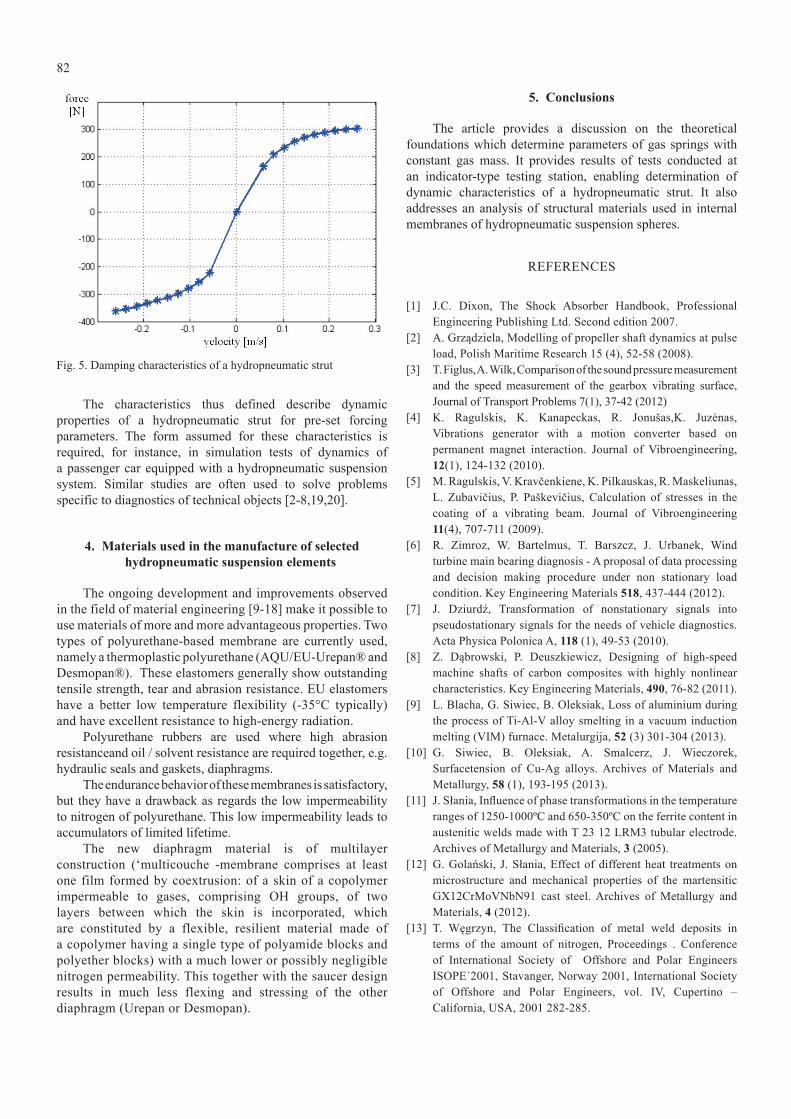
Fig. 7 provides graphs of averaged loops of force changes in the function of linear velocity for an increasing value of the forcing velocity.
Fig. 4. Graph of force changes in the function of velocity for different frequencies of forcing
Based on the foregoing graphs, specific points were established where the linear velocity reached its maximum value on the motion of compression and tension, and with reference to these velocities, values of damping forces were read. It is the method used to determine damping characteristics of the hydropneumatic strut for the given load value as well as the range of velocity changes envisaged.
82
Fig. 5. Damping characteristics of a hydropneumatic strut
The characteristics thus defined describe dynamic properties of a hydropneumatic strut for pre-set forcing parameters. The form assumed for these characteristics is required, for instance, in simulation tests of dynamics of a passenger car equipped with a hydropneumatic suspension system. Similar studies are often used to solve problems specific to diagnostics of technical objects [2-8,19,20].
4. Materials used in the manufacture of selected hydropneumatic suspension elements
The ongoing development and improvements observed in the field of material engineering [9-18] make it possible to use materials of more and more advantageous properties. Two types of polyurethane-based membrane are currently used, namely a thermoplastic polyurethane (AQU/EU-Urepan® and Desmopan®). These elastomers generally show outstanding tensile strength, tear and abrasion resistance. EU elastomers have a better low temperature flexibility (-35°C typically) and have excellent resistance to high-energy radiation.
Polyurethane rubbers are used where high abrasion resistanceand oil / solvent resistance are required together, e.g. hydraulic seals and gaskets, diaphragms.
The endurance behavior of these membranes is satisfactory, but they have a drawback as regards the low impermeability to nitrogen of polyurethane. This low impermeability leads to accumulators of limited lifetime.
The new diaphragm material is of multilayer construction (‘multicouche -membrane comprises at least one film formed by coextrusion: of a skin of a copolymer impermeable to gases, comprising Oh groups, of two layers between which the skin is incorporated, which are constituted by a flexible, resilient material made of a copolymer having a single type of polyamide blocks and polyether blocks) with a much lower or possibly negligible nitrogen permeability. This together with the saucer design results in much less flexing and stressing of the other diaphragm (Urepan or Desmopan).
5. Conclusions
The article provides a discussion on the theoretical foundations which determine parameters of gas springs with constant gas mass. It provides results of tests conducted at an indicator-type testing station, enabling determination of dynamic characteristics of a hydropneumatic strut. It also addresses an analysis of structural materials used in internal membranes of hydropneumatic suspension spheres.
REfERENCES
[1] J.C. Dixon, The Shock Absorber Handbook, Professional Engineering Publishing Ltd. Second edition 2007.
[2] a. Grządziela, Modelling of propeller shaft dynamics at pulse load, Polish Maritime Research 15 (4), 52-58 (2008).
[3] T. figlus, a. Wilk, Comparison of the sound pressure measurement and the speed measurement of the gearbox vibrating surface, Journal of Transport Problems 7(1), 37-42 (2012)
[4] K. Ragulskis, K. Kanapeckas, R. Jonušas,K. Juzėnas, vibrations generator with a motion converter based on permanent magnet interaction. Journal of vibroengineering, 12(1), 124-132 (2010).
[5] M. Ragulskis, v. Kravčenkiene, K. pilkauskas, R. Maskeliunas, l. Zubavičius, p. paškevičius, Calculation of stresses in the coating of a vibrating beam. Journal of vibroengineering 11(4), 707-711 (2009).
[6] R. Zimroz, W. Bartelmus, T. Barszcz, J. Urbanek, Wind turbine main bearing diagnosis - A proposal of data processing and decision making procedure under non stationary load condition. Key Engineering Materials 518, 437-444 (2012).
[7] J. Dziurdź, Transformation of nonstationary signals into pseudostationary signals for the needs of vehicle diagnostics. Acta Physica Polonica A, 118 (1), 49-53 (2010).
[8] Z. Dąbrowski, p. Deuszkiewicz, Designing of high-speed machine shafts of carbon composites with highly nonlinear characteristics. Key Engineering Materials, 490, 76-82 (2011).
[9] l. Blacha, G. Siwiec, B. Oleksiak, loss of aluminium during the process of Ti-al-v alloy smelting in a vacuum induction melting (vIM) furnace. Metalurgija, 52 (3) 301-304 (2013).
[10] G. Siwiec, B. Oleksiak, a. Smalcerz, J. Wieczorek, Surfacetension of Cu-Ag alloys. Archives of Materials and Metallurgy, 58 (1), 193-195 (2013).
[11] J. Słania, Influence of phase transformations in the temperature ranges of 1250-1000ºC and 650-350ºC on the ferrite content in austenitic welds made with T 23 12 LRM3 tubular electrode. Archives of Metallurgy and Materials, 3 (2005).
[12] G. Golański, J. Słania, Effect of different heat treatments on microstructure and mechanical properties of the martensitic GX12CrMovNbN91 cast steel. archives of Metallurgy and Materials, 4 (2012).
[13] T. Węgrzyn, The Classification of metal weld deposits in terms of the amount of nitrogen, Proceedings . Conference of International Society of Offshore and polar Engineers ISOpE´2001, Stavanger, Norway 2001, International Society of Offshore and polar Engineers, vol. Iv, Cupertino – California, USA, 2001 282-285.
83
Received: 20 February 2015.
[14] T. Węgrzyn, Mathematical Equations of the Influence of Molybdenum and Nitrogen in Welds. Conference of International Society of Offshore and polar Engineers ISOpE´2002, Kita Kyushu, Japan 2002, Copyright by International Society of Offshore and polar Engineers, vol. Iv, ISBN 1-880653-58-3, Cupertino – California – USa 2002.
[15] T. Węgrzyn, J. piwnik, B. Łazarz, D. hadryś, Main micro-jet cooling gases for steel welding. Archives of Materials and Metallurgy 58(2), 551-553 (2013).
[16] A. Lisiecki, Diode laser welding of high yield steel. Proceedings of SPIE, Laser Technology, Applications of Lasers 8703, 22 (2012).
[17] a. lisiecki, Welding of titanium alloy by Disk laser. Proceedings of SPIE, Laser Technology, Applications of Lasers, 87030 (2013).
[18] A. Lisiecki, Diode laser welding of high yield steel. Proceedings of SPIE, Laser Technology, Applications of Lasers, 8703 22 (2012)
[19] T. Barszcz, J. Urbanek, Monitorowanie i diagnostyka maszyn wirnikowych- praktyczny podręcznik wibroakustyki. pIB, Kraków (2008).
[20] R. Burdzik, Ł. Konieczny, Research on structure, propagation
and exposure to general vibration in passenger car for different damping parameters, Journal of vibroengineering 15(4), 1680-1688 (2013).
[21] C. Cempel, Wibroakustyczna diagnostyka maszyn. poi, poznań (1985).
[22] W. Borkowski, S. Konopka, l. prochowski, Dynamika maszyn roboczych, WNT, Warszawa (1996).
[23] D. Eulenbach, hydropneumatische Niveauregelelemente, Seminars Federungs - und Dämpfungssysteme für Straßen- und Schienenfahrzeuge, (2004).
[24] Ł. Konieczny, The statistical analysis of damping parameters of hydraulic shock absorbers. Diagnostyka 15 (2), 49-52, (2014).
[25] Ł. Konieczny, R. Burdzik, p. folega, a.N. Wieczorek, Determination of the damping characteristics of hydro pneumatic suspension strut. Journal of Measurement Engineering 1 (3), 155-158, (2013).
[26] Ł. Konieczny, R. Burdzik, Comparison of characteristics of the components used in mechanical and non-conventional automotive suspensions. Mechatronic systems, mechanics and materials II. Trans Tech Publications, , Solid State Phenomena 210, 1012-0394, (2014).


![Apeiron Volume 41 Issue 2 2008 [Doi 10.1515%2FAPEIRON.2008.41.2.171] Johnston, Rebekah -- The Existence of Powers](https://static.fdocuments.in/doc/165x107/55cf8f6d550346703b9c48c0/apeiron-volume-41-issue-2-2008-doi-1015152fapeiron2008412171-johnston.jpg)