DOI: 10.1515/amm-2016-0266 - IMIM · At the time of a 121 submerged arc welding by the solid...
8
1. Introduction At the time of a continuous economy growth there is an increasing need for steel constructions particularly in the following sectors: power engineering and metallurgy. Mentioned need refers mostly to manufacturing huge and heavy welded constructions such as steam turbine castings for conventional and nuclear power plants, or convection heaters for metallurgy. Above constructions are characterised by a great number of thick-walled welded joints. Manufacturers of such constructions often stand in front of a problem which method of welding is the most appropriate to make joints. In order to make a right decision specialists need to possess all the necessary information relating to the technology of welding, characteristics of materials, and also properties of welded joints. The aim of an article is to take examinations of a technology of welding of thick-walled welded joints made from fine-grained steel standard annealed, and designed for pressure devices. Examination of a welding technology taken according to the PN-EN ISO 15614-1 standard includes a preparation of a technology of welding, and doing destructive and non-destructive tests of welded joints. The most popular methods of welding were used to make sample thick-walled joints namely metal active gas welding in an active gas shield by the solid welding electrode (MAG -135), and submerged arc welding by the solid welding electrode (SAW 121). Results of examinations of welding technologies should provide numerous valuable information, which are vital to make proper decisions while choosing a technology of welding. 2. Characteristics of welding methods Two methods of welding [1] were used to take an examination of the welding technology i.e.: • 135 metal active gas welding in an active gas shield by the solid welding electrode (MAG) • 121 submerged arc welding by the solid welding electrode (SAW). Above methods fulfil the requirements which are put on thick-walled joints both by means of technology and efficiency. 2.1. Welding by the MAG method Welding by the MAG (Eng. Metal Active Gas) method refers to melting the edges of the joint’s elements and the material of the melting electrode by the heat of an electric arc in the gas shield or a gaseous mixture. A source of the heat is an electric arc, which is arcing in a gaseous atmosphere between a melting electrode and a welded material [2, 3]. Nowadays, welding by the MAG method is used in many different types, and in many forms of transferring a metal in the welding arc [4]. The most popular method 135, which can be used to make high quality joints in the steel constructions, was used to take examinations. Above method allows to obtain proper joints both in respect of technology, and metallurgy for the following types of steel: carbon steel, low-alloyed steel, high-alloyed steel and special-purpose steel. The 135 method is characterised by a possibility to weld in all positions, both a manual and mechanized welding [3]. 2.2. Welding by the SAW method Welding by the submerged arc (Eng. Submerged Arc Welding; SAW) method refers to melting the edges of the joint’s elements and the material of the melting electrode by the heat of an electric arc under a layer of granular flux. A source of the heat is an electric arc, which is arcing in a gaseous Arch. Metall. Mater., Vol. 61 (2016), No 3, p. 1641–1648 DOI: 10.1515/amm-2016-0266 R. KRAWCZYK* ,# AN ANALYSIS OF THE JOINTS’ PROPERTIES OF FINE-GRAINED STEEL WELDED BY THE MAG AND SAW METHODS The article presents an analysis of properties of welded joints of fine-grained steel of P460NH type used more and more often in the modern constructions. A process of examining a technology of welding has been carried out on the thick-walled butt joints of sheet metal by two methods of welding namely MAG – 135 and SAW – 121. The article deals with a topic of optimizing a process of welding thick-walled welded joints of fine-grained steel due to their mechanicalproperties and efficiency. Keywords: welding, properties of joints, fine-grained types of steel, non-destructive, and destructive testing, optimizing a process of welding * Politechnika częstochowska, 69 J.h. Dąbrowskiego str., 42-201 częstochowa, PolanD # Corresponding author: [email protected]
Transcript of DOI: 10.1515/amm-2016-0266 - IMIM · At the time of a 121 submerged arc welding by the solid...

1. Introduction
At the time of a continuous economy growth there is an increasing need for steel constructions particularly in the following sectors: power engineering and metallurgy. Mentioned need refers mostly to manufacturing huge and heavy welded constructions such as steam turbine castings for conventional and nuclear power plants, or convection heaters for metallurgy. Above constructions are characterised by a great number of thick-walled welded joints. Manufacturers of such constructions often stand in front of a problem which method of welding is the most appropriate to make joints. In order to make a right decision specialists need to possess all the necessary information relating to the technology of welding, characteristics of materials, and also properties of welded joints.
The aim of an article is to take examinations of a technology of welding of thick-walled welded joints made from fine-grained steel standard annealed, and designed for pressure devices. Examination of a welding technology taken according to the PN-EN ISO 15614-1 standard includes a preparation of a technology of welding, and doing destructive and non-destructive tests of welded joints. The most popular methods of welding were used to make sample thick-walled joints namely metal active gas welding in an active gas shield by the solid welding electrode (MAG -135), and submerged arc welding by the solid welding electrode (SAW 121). Results of examinations of welding technologies should provide numerous valuable information, which are vital to make proper decisions while choosing a technology of welding.
2. Characteristics of welding methods
Two methods of welding [1] were used to take an examination of the welding technology i.e.:
• 135 metal active gas welding in an active gas shield by the solid welding electrode (MAG)
• 121 submerged arc welding by the solid welding electrode (SAW).
Above methods fulfil the requirements which are put on thick-walled joints both by means of technology and efficiency.
2.1. Welding by the MAG method
Welding by the MAG (Eng. Metal Active Gas) method refers to melting the edges of the joint’s elements and the material of the melting electrode by the heat of an electric arc in the gas shield or a gaseous mixture. A source of the heat is an electric arc, which is arcing in a gaseous atmosphere between a melting electrode and a welded material [2, 3]. Nowadays, welding by the MAG method is used in many different types, and in many forms of transferring a metal in the welding arc [4]. The most popular method 135, which can be used to make high quality joints in the steel constructions, was used to take examinations. Above method allows to obtain proper joints both in respect of technology, and metallurgy for the following types of steel: carbon steel, low-alloyed steel, high-alloyed steel and special-purpose steel. The 135 method is characterised by a possibility to weld in all positions, both a manual and mechanized welding [3].
2.2. Welding by the SAW method
Welding by the submerged arc (Eng. Submerged Arc Welding; SAW) method refers to melting the edges of the joint’s elements and the material of the melting electrode by the heat of an electric arc under a layer of granular flux. A source of the heat is an electric arc, which is arcing in a gaseous
Arch. Metall. Mater., Vol. 61 (2016), No 3, p. 1641–1648
DOI: 10.1515/amm-2016-0266
R. KRAWczyK*,#
An AnAlySIS of the joIntS’ propertIeS of fIne-GrAIned Steel Welded by the MAG And SAW MethodS
The article presents an analysis of properties of welded joints of fine-grained steel of P460NH type used more and more often in the modern constructions. A process of examining a technology of welding has been carried out on the thick-walled butt joints of sheet metal by two methods of welding namely MAG – 135 and SAW – 121. The article deals with a topic of optimizing a process of welding thick-walled welded joints of fine-grained steel due to their mechanicalproperties and efficiency.
Keywords: welding, properties of joints, fine-grained types of steel, non-destructive, and destructive testing, optimizing a process of welding
* Politechnika częstochowska, 69 J.h. Dąbrowskiego str., 42-201 częstochowa, PolanD# corresponding author: [email protected]
1642
atmosphere made of a melted flux between a melting electrode and a welded material [2]. This method is characterised by a high purity of metallurgy, and very good properties of the joints of all types of steel used for welding constructions, as well as other materials. The 121 method is also characterised by the high efficiency of welding, and is often dedicated to make joints of thick-walled elements. It allows to weld only in the flat and horizontal positions of welding in mechanized conditions [5].
3. Materials used for examinations
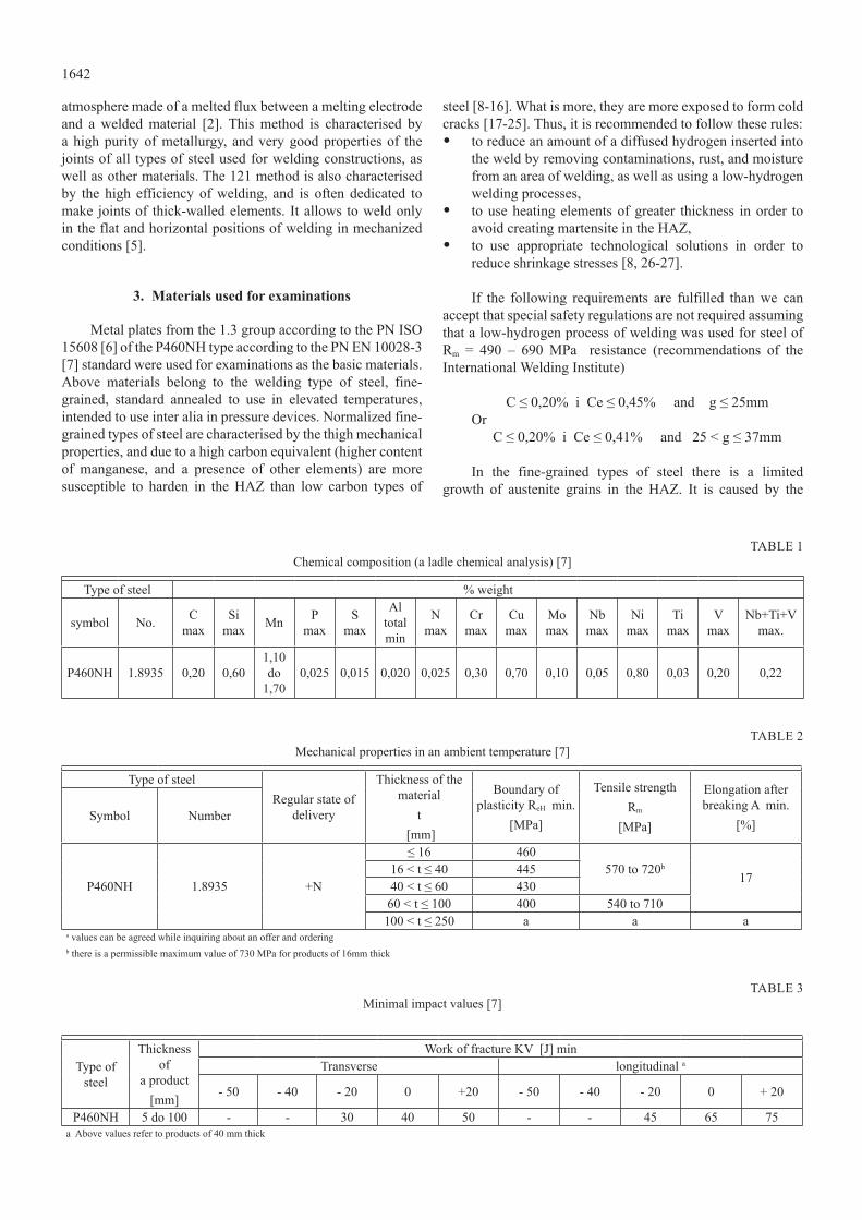
Metal plates from the 1.3 group according to the PN ISO 15608 [6] of the P460NH type according to the PN EN 10028-3 [7] standard were used for examinations as the basic materials. Above materials belong to the welding type of steel, fine-grained, standard annealed to use in elevated temperatures, intended to use inter alia in pressure devices. Normalized fine-grained types of steel are characterised by the thigh mechanical properties, and due to a high carbon equivalent (higher content of manganese, and a presence of other elements) are more susceptible to harden in the HAz than low carbon types of
steel [8-16]. What is more, they are more exposed to form cold cracks [17-25]. Thus, it is recommended to follow these rules:• to reduce an amount of a diffused hydrogen inserted into
the weld by removing contaminations, rust, and moisture from an area of welding, as well as using a low-hydrogen welding processes,
• to use heating elements of greater thickness in order to avoid creating martensite in the HAz,
• to use appropriate technological solutions in order to reduce shrinkage stresses [8, 26-27].
If the following requirements are fulfilled than we can accept that special safety regulations are not required assuming that a low-hydrogen process of welding was used for steel of Rm = 490 – 690 MPa resistance (recommendations of the International Welding Institute)
c ≤ 0,20% i ce ≤ 0,45% and g ≤ 25mmOr
c ≤ 0,20% i ce ≤ 0,41% and 25 < g ≤ 37mm
In the fine-grained types of steel there is a limited growth of austenite grains in the HAz. It is caused by the
table 1chemical composition (a ladle chemical analysis) [7]
Type of steel % weight
symbol No. c max
Si max Mn P
maxS
max
Al total min
N max
cr max
cu max
Mo max
Nb max
Ni max
Ti max
V max
Nb+Ti+V max.
P460NH 1.8935 0,20 0,601,10 do
1,700,025 0,015 0,020 0,025 0,30 0,70 0,10 0,05 0,80 0,03 0,20 0,22
table 2Mechanical properties in an ambient temperature [7]
Type of steelRegular state of
delivery
Thickness of the material
t [mm]
boundary of plasticity ReH min.
[MPa]
Tensile strengthRm
[MPa]
Elongation after breaking A min.
[%]Symbol Number
P460NH 1.8935 +N
≤ 16 460570 to 720b
1716 < t ≤ 40 44540 < t ≤ 60 43060 < t ≤ 100 400 540 to 710100 < t ≤ 250 a a a
a values can be agreed while inquiring about an offer and ordering b there is a permissible maximum value of 730 MPa for products of 16mm thick
table 3Minimal impact values [7]
Type of steel
Thickness of
a product[mm]
work of fracture kV [J] minTransverse longitudinal a
- 50 - 40 - 20 0 +20 - 50 - 40 - 20 0 + 20
P460NH 5 do 100 - - 30 40 50 - - 45 65 75a Above values refer to products of 40 mm thick

1643
precipitations of carbides, nitrides or carbonitrides of micro-alloyed elements. Fine-grained austenite while changing in the process of melting of welded joint makes structures of high impact value. A general characteristics of fine-grained type of steel used in the P460NH examinations is presented in the tables 1, 2 and 3.
Meeting the requirements of the PN-EN 10028-3 standard allows to presume a compatibility with appropriate requirements of the 97/23/we pressure directive. steel produced according to the above standard can be used to make pressure devices, which can be exploited in the European Union.
4. examinations of a technology of welding
certain examinations of sample welded joints were taken in order to make an assessment of a technology of welding taking into account acceptance criteria included in the standard, which relates to an examination of a technology of welding namely
the PN-EN ISO 15614-1 standard. Examinations were taken on the sample joints made according to the initial technology conditions for the MAG and SAW methods of welding.
4.1. Sample welded joints
The PN-EN ISO 15614-1 standard describes requirements relating to an assessment of an initial manual welding technology by means of examinations taken on the sample joints. Sample joints for examinations were prepared from the P460NH steel of 40mm thick metal plates with an X bevelled for a double-sided butt welding according to the requirements of the mentioned standard. There were two joints measuring 300x350mm for welding by the 135 method in order to make sample joints in two positions horizontal – Pc, and vertical upwards progression - PF positions. For welding by the 121 method a joint measuring 300x700mm was prepared. An initial manual welding technology for making sample joints
table 4Details relating to the Mag method in the horizontal position - Pc
bead sequence
Welding process
Filler metal size
[mm]
current
[A]
Voltage
[V]
Travel speed[cm/min]
PolarityHeat input
[kJ/cm]1 135 1,2 140-160 17-20 18-22 Dc/+ 5,2-5,82 135 1,2 180-200 20-21 24-25 Dc/+ 5,9-6,5
3-n 135 1,2 200-240 21-24 25-30 Dc/+ 6,5-7,51’ 135 1,2 180-200 20-21 24-25 Dc/+ 5,9-6,5
2-n’ 135 1,2 200-240 21-24 25-30 Dc/+ 6,5-7,5solid wire-classification: g2Mo according to the en iso 14341-a (ok aristorod 13.09)
Shielding gas type: Ferromix c18 – M21 according to the PN-EN ISO 14175
gas flow rate: [l/min]: 14 - 18 Preheat temperature: ≥ 100°c
Heat treatment: not applicable interpass temperature: ≤ 250°c
table 5Details relating to the Mag method in the vertical upwards progression PF
bead sequence
Welding process
Filler metal size
[mm]
current
[A]
Voltage
[V]
Travel speed[cm/min]
PolarityHeat input
[kJ/cm]1 135 1,2 120-140 16-18 12-16 Dc/+ 6,2-6,12 135 1,2 180-220 20-22 16-18 Dc/+ 8,7-10,5
3-n 135 1,2 200-240 21-24 16-18 Dc/+ 10,1-12,51’ 135 1,2 180-220 20-22 16-18 Dc/+ 8,7-10,5
2-n’ 135 1,2 200-240 21-24 16-18 Dc/+ 10,1-12,5solid wire-classification:: g2Mo according to the en iso 14341-a (ok aristorod 13.09)
Shielding gas type: Ferromix c18 – M21 according to the PN-EN ISO 14175
gas flow rate: [l/min]: 14 - 18 Preheat temperature: ≥ 100°c
Heat treatment: not applicable interpass temperature: ≤ 250°c

1644
was prepared where detailed welding conditions for particular processes were included. The key data of an initial manual welding technology of sample welded joints is given in tables 4, 5 and 6.
A view from the face side of the weld of fragments of welded joints made by the MAG method is shown in the picture 1a and b, while a welded joint made by the SAW method in the picture 2.
a) b)
Fig. 1. A view of the face of welds made by the 135 method: a) in a horizontal position - Pc, b) in a vertical upwards progression - PF
Fig. 2. A view of the face of the weld made by the 121 method in a flat position – PA
4.2. examinations of sample welded joints
checking a technology of welding according to the PN-EN ISO 15614-1 standard requires carrying out examinations on the sample joints in compliance with the requirements included in table 7, and relating to a given example i.e. butt joints of metal sheets with a full joint penetration.
table 7Range of control and examination of sample joints according to the
Pn-en iso 15614-1 standard [9]
Sample joint Type of examination Scope of examination
butt joint with a complete joint
penetration
Visual testingRadiographic or ultrasonic
testingDetecting surface cracksTransverse tensile testTransverse bend testImpact strength test
Hardness testMacroscopic examinations
100 %100 %100 %
2 samples4 samples
2 setsrequired1 sample
At first, non-destructive testing were done in a full range for all sample joints i.e. visual testing (VT), magnetic particle testing (MT), ultrasonic testing (UT), and radiography testing (RT). Taking into account requirements of the PN-EN ISO 15614-1 standard a number of examination methods was extended into a radiography testing. Tests were done after 48 hours from finishing a welding process. Quality level b was taken as an acceptance criterion according to the PN-EN ISO 5817 standard. Suitable standard specifications were used to do non-destructive testing and an inspection of joints, as well as proper acceptance criteria presented in table 8 are used.
table 6Details relating to the saw method in the flat position – Pa with a joint penetration made by the Mag method
bead sequence
Welding process
Filler metal size
[mm]
current
[A]
Voltage
[V]
Travel speed[cm/min]
PolarityHeat input
[kJ/cm]1 135 1,2 150-170 20-22 24-26 Dc/+ 4,9-5,62 135 1,2 180-200 23-25 21-23 Dc/+ 7,7-8,53 121 4,0 350-380 26-27 55-60 Dc/+ 8,9-9,2
4-n 121 4,0 450-500 29-31 30-32 Dc/+ 23,5-26,31’-n’ 121 4,0 450-500 29-31 30-32 Dc/+ 23,5-26,3 135: g2Mo according to the en iso 14341-a (ok aristorod 13.09)Solid wire-classification: 121: G3Mo according to the EN ISO 14171-A (OK AristoRod 12.34)
Shielding gas type: Ferromix c18 – M21 according to the PN-EN ISO 14174
Flux type: s a ab 1 67 ac h05 according to the Pn-en iso 14175 (ok Flux 10.71)
Drying time: 3h Drying temperature: 300-350°c
gas flow rate: [l/min]: 14 - 18 Preheat temperature: ≥ 100°c
Heat treatment: not applicable interpass temperature: ≤ 250°c
1645
after obtaining positive results from nDt, samples were taken for destructive testing including tensile and transverse bend tests, impact strength test, macroscopic examination and hardness penetration pattern. Appropriate standard specifications were used to do destructive testing, and to make an assessment of joints, as well as relevant acceptance criteria were adopted, which is given in the table 9.
4.3. results of examinations of sample welded joints
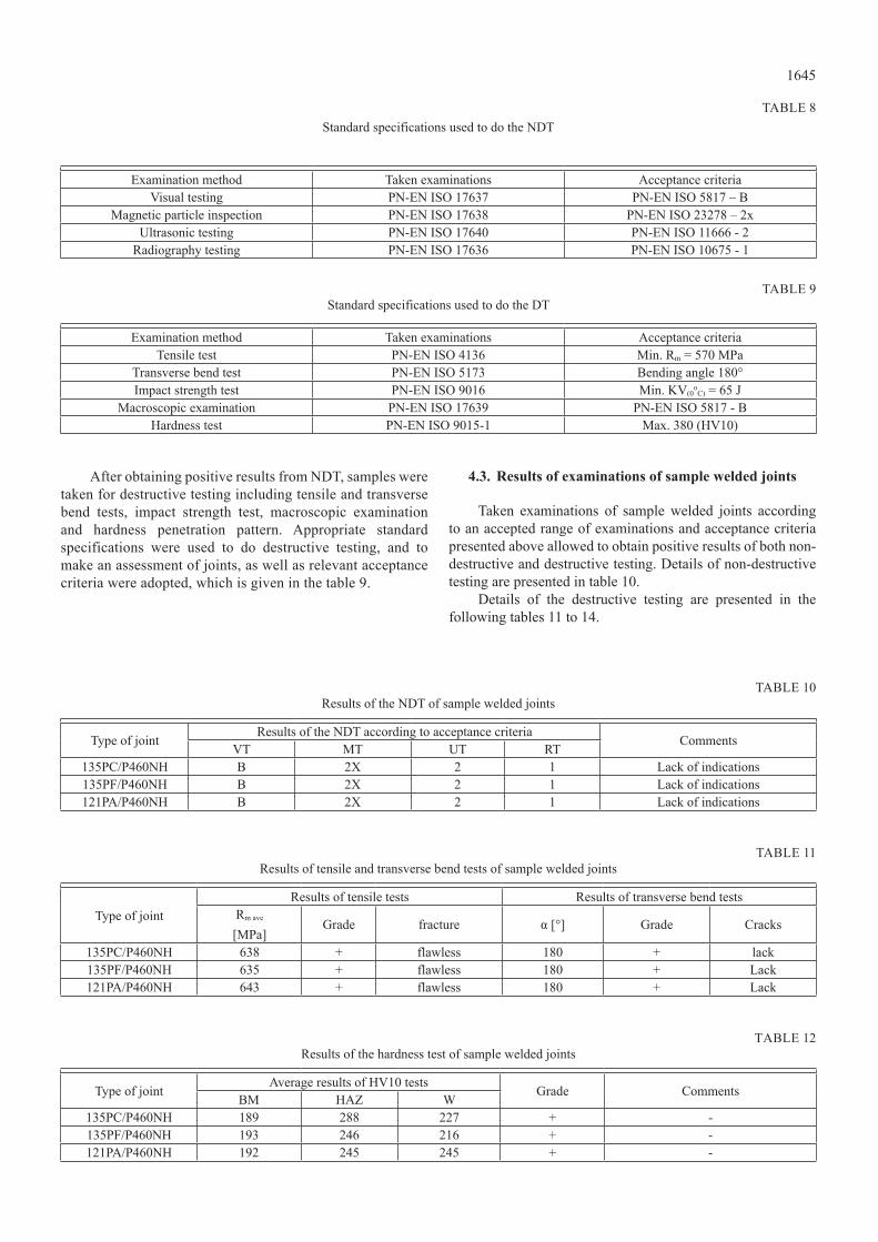
Taken examinations of sample welded joints according to an accepted range of examinations and acceptance criteria presented above allowed to obtain positive results of both non-destructive and destructive testing. Details of non-destructive testing are presented in table 10.
Details of the destructive testing are presented in the following tables 11 to 14.
table 8standard specifications used to do the nDt
Examination method Taken examinations Acceptance criteriaVisual testing PN-EN ISO 17637 Pn-en iso 5817 – b
Magnetic particle inspection PN-EN ISO 17638 PN-EN ISO 23278 – 2xUltrasonic testing PN-EN ISO 17640 PN-EN ISO 11666 - 2
Radiography testing PN-EN ISO 17636 PN-EN ISO 10675 - 1
table 9standard specifications used to do the Dt
Examination method Taken examinations Acceptance criteriaTensile test PN-EN ISO 4136 Min. Rm = 570 MPa
Transverse bend test PN-EN ISO 5173 bending angle 180°Impact strength test Pn-en iso 9016 Min. KV(0
oc) = 65 J
Macroscopic examination Pn-en iso 17639 Pn-en iso 5817 - bHardness test Pn-en iso 9015-1 Max. 380 (HV10)
table 10results of the nDt of sample welded joints
Type of joint results of the nDt according to acceptance criteria comments VT MT UT RT135Pc/P460nh b 2X 2 1 Lack of indications 135PF/P460nh b 2X 2 1 Lack of indications121Pa/P460nh b 2X 2 1 Lack of indications
table 11Results of tensile and transverse bend tests of sample welded joints
Type of jointResults of tensile tests Results of transverse bend tests
Rm ave
[MPa]Grade fracture α [°] Grade cracks
135Pc/P460nh 638 + flawless 180 + lack135PF/P460nh 635 + flawless 180 + Lack 121Pa/P460nh 643 + flawless 180 + Lack
Table 12Results of the hardness test of sample welded joints
Type of joint Average results of HV10 tests Grade comments bM HAz W 135Pc/P460nh 189 288 227 + -135PF/P460nh 193 246 216 + -121Pa/P460nh 192 245 245 + -

1646
Tensile strength and transverse bend tests of sample welded joints made by the 121 and 135 methods (in the Pc and PF positions) gave positive results with similar effects. Requirements related to the technology of welding were also fulfilled.
The highest level of hardness was found in HAz of the joint welded by the 135 method in the Pc position (the lowest level of heat input). Heat affected zone was characterised by the highest hardness in all examples. In the 121 method the same level of hardness was found both in the weld and in haz. base material was characterised by the lower hardness in all examples. In all examples a level of hardness proved a regularity of the technology of welding.
The highest work of fracture was obtained in the welded joint made by the 135 method in the horizontal position Pc (the lowest amount of heat input). A joint welded by the 135 method in the vertical upwards progression PF (the highest amount of heat input) was characterised by the lowest work of fracture. Joints welded by the 135 method in the horizontal Pc and vertical upwards progression PF positions are characterised by a different impact strength. In case of welding in the vertical upwards progression position PF an amount of heat input is higher than in case of welding in the horizontal position Pc, and therefore work of fracture is much lower in the horizontal position. Work of fracture near the HAz in case of all sample
table 13results of impact strength of sample welded joints – work of fracture kV (0°c)
Type of jointAn area
of an examination
average results of examinations kV [J]Grade comments W HAz
135Pc/P460nht 2 85 169 + -t/2 111 177 + -t-2 124 133 + -
135PF/P460nht 2 69 96 + -t/2 89 147 + -t-2 79 161 + -
121Pa/P460nht 2 95 99 + -t/2 103 118 + -t-2 77 119 + -
table 14Results of macroscopic examinations of sample welded joints
Type of joint A cross-section view Description
135Pc/P460nh
complete joint penetration. A proper fusion into a base material. A regular sequence of beads. A width of HAz is 2,5-3,0mm. Weld’s geometry and the whole joint is regular with a slight irregularity of the face of the weld. Lack of important welding defects (slight inclusions). In the central area of the base material there is a dark strip of a different structure.
135PF/P460nh
complete joint penetration. A proper fusion into a base material. A regular sequence of beads. A width of HAz is 2-2,5mm. Weld’s geometry and the whole joint is regular. Lack of important welding defects (slight inclusions). In the central area of the base material there is a dark strip of a different structure.
135Pc
135PF

1647
joints obtained much higher value than in the weld. All the joints fulfilled requirements relating to the impact strength tests of examined technologies of welding.
Results of macroscopic examinations showed a proper structure of all sample joints, moreover, there were any important welding defects. Only, in the welding test of the 135 method in the horizontal position Pc slight inclusions were observed. In the particular samples of welded joints there were slight differences in the width of the heat affected zone HAz. The widest HAz was observed in the joint welded by the 121 method.
Apart from the used method, and the welding position welded joints fulfilled the requirements of the quality level b according to the PN-EN ISO 5817 standard.
5. An assessment of welding efficiency
Sample welded joints were also assessed due to their efficiency of welding. This factor is essential not only from an economical point of view, but also thermal properties obtained in particular processes. Table 15 provides comparative results connected with efficiency of used methods of welding in examining a technology of welding fine-grained steel.
table 15An efficiency of used methods of welding
Type of sample joint 121 – PA
135 – Pc 135 – PF
A number of beads of the weld 13 33 25Time of welding 1RM of the weld
[mm]60 160 200
An average amount of heat input[kJ/cm]
25 7 10
Welding by the submerged arc (short time of welding with a relatively small amount of beads) became the most efficient. Much less efficient method of welding was the MAG-135 method in the Pc position, and even less efficient appeared to be a welding test in the PF position. An efficiency of a welding process by the submerged arc in comparison to the MAG method appeared to be 2,5 times bigger. In a reverse situation there is a use of energy in particular processes, which is directly connected with a heat input.
6. Summary
On the base of taken examinations it can be assumed that the most favourable method of welding of thick-walled joints from fine-grained types of steel is a process of welding by the submerged arc (121). Mentioned method combines both a high efficiency and fulfilling all the requirements connected with mechanical properties. There is however, a certain limitation related to a possibility of welding only in the flat position (PA), therefore it prevents welding constructions of complex shapes, which require different welding positions.
Therefore, for constructions of complex shapes the most appropriate method is a submerged arc welding by the solid electrode in an active gas shield. Above method fulfils all the mechanical properties which are put on the fine-grained types of steel.
There were not any considerable differences in the quality level of welded joints in the used methods of welding. All the methods of welding allowed to obtain the highest quality level b according to the Pn-en iso 5817 standard.
If a high impact strength of the welded joints is required, it is recommended to use the 135 method, especially in the Pc position. Joints welded by the 121 method are characterised by the high impact strength of the work of fracture.
If a high plasticity, and therefore low hardness is required, than it is recommended to use the 121 and 135 methods of welding in PF positions. Above methods are characterised by the higher heat input.
Taking everything into account, it can be claimed that while choosing a proper technology of welding both quality requirements of finished joints, possibilities of implementing the process and economical issues should be considered.
REFERENcES
[1] PN-EN ISO 4063:2011, Spawanie i procesy pokrewne – Nazwy i numery procesów
[2] Praca zbiorowa, Poradnik inżyniera – spawalnictwo tom ii, WNT, Warszawa 2005
[3] b. Pierożek, J. lassociński, spawanie łukowe stali w osłonach gazowych. wnt, warszawa 1987
[4] r. krawczyk, zakresy parametrów spawania w zależności od przenoszenia metalu w łuku spawalniczym. biuletyn instytutu spawalnictwa. nr 4/2014
121Pa/P460nh
complete joint penetration. A proper fusion into a base material. A regular sequence of beads. A width of HAz is 2-4,5mm. Weld’s geometry and the whole joint is regular. Lack of important welding defects (slight inclusions). In the central area of the base material there is a dark strip of a different structure.
121PA
1648
[5] J. węgrzyn, r. korkiewicz, automatyczne spawanie i napawanie pod topnikiem, wnt, warszawa 1966
[6] PN-cR ISO 15608:2002, Spawanie - Wytyczne systemu podziału materiałów metalowych na grupy
[7] Pn-en 10028-3:2009, wyroby płaskie ze stali na urządzenia ciśnieniowe - część 3: stale spawalne drobnoziarniste normalizowane
[8] J. brózda, stale konstrukcyjne i ich spawalność, instytut spawalnictwa, gliwice 2009
[9] Pn-en iso 15614-1:2008, specyfikacja i kwalifikowanie technologii spawania metali - badanie technologii spawania - część 1: spawanie łukowe i gazowe stali oraz spawanie łukowe niklu i stopów niklu
[10] t. węgrzyn, J. Piwnik, b. Łazarz, D. hadryś, Main micro-jet cooling gases for steel welding, Archives of Metallurgy and Materials 58, issue 2, 555 – 557 (2013).
[11] t. węgrzyn, J. Piwnik, D. hadryś, oxygen in steel wMD after welding with micro-jet cooling, Archives of Metallurgy and Materials 58, issue 4, 1067 – 1070 (2013).
[12] w. tarasiuk, b. szczucka –lasota, J. Piwnik, w. Majewski, tribological Properties of super Field weld with Micro-Jet Process, Adv. Mat. Res. 1036, 452-457 (2014).
[13] t. węgrzyn, t. Piwnik, J. wieszała, D. hadryś, control over the steel welding structure parameters by micro-jet cooling. Archives of Metallurgy and Materials, ISS 1, 57, 3, 679-685 (2012).
[14] t. węgrzyn, the classification of Metal weld Deposits in terms of the amount of oxygen. Proc oF isoPe, iV, 1999, 212 – 216.
[15] t. węgrzyn, the classification of Metal weld Deposits in Terms of the Amount of Nitrogen. Procedings of ISOPE´2000, V, 130 – 134 (2000).
[16] b. szczucka-lasota, b. Formanek, a. hernas, k. szymański, Oxidation models of the growth of corrosion products on the intermetallic coatings strengthened by a fine dispersive al2O3. Journal of Materials Processing technology 164-165, 935 – 939 (2005).
[17] J. słania, influence of phase transformations in the temperature ranges of 1250-1000ºc and 650-350ºc on the ferrite content in
austenitic welds made with T 23 12 LRM3 tubular electrode. Metallurgy and Materials, 3, 2010-2014 (2005).
[18] r. burdzik, P. Folęga, b. Łazarz, z. stanik, J. warczek, Analysis of the impact of surface layer parameters on wear intensity of friction pairs. Archives of Metallurgy and Materials, 57, 4, 987 – 993 (2012).
[19] k. lukaszkowicz, a. kriz, J. sondor: structure and adhesion of thin coatings deposited by PVD technology on the X6crNiMoTi17-12-2 and X40 crMoV5-1 steel substrates. Materials Science and Engineering, 51, 40-47.
[20] a. lisiecki, Diode laser welding of high yield steel. Proc. of SPIE Vol. 8703, Laser Technology 2012, Applications of lasers 87030s (January 22, 2013), Doi: 10.1117/12.2013429.
[21] a. lisiecki, welding of titanium alloy by Disk laser. Proc. of SPIE Vol. 8703, Laser Technology 2012: Applications of lasers 87030t (January 22, 2013), Doi: 10.1117/12.2013431.
[22] g. golański, a. zieliński, J. słania, J. Jasak, Mechanical Properties of VM12 steel after 30 000hrs of ageing at 600°c temperature. Archives of Metallurgy and Materials, 59, 2 (2014).
[23] g. golański, P. gawień, J. słania, examination of coil Pipe butt Joint Made of 7crMoVtib10 - 10(t24) steel after Service, Archives of Metallurgy and Materials, 57, 2, (2012).
[24] b. oleksiak, J. labaj, J. wieczorek, a. blacha–grzechnik, r. burdzik, surface tension of cu-bi alloys and wettability in a liquid alloy - refractory material - gaseous phase system, Arch. Metall. Mater. 59(1), 281-285 (2014).
[25] b. oleksiak, g. siwiec, a. blacha-grzechnik, J. wieczorek, The obtained of concentrates containing precious metals for pyrometallurgical processing, Metalurgija 53(4), 605-608 (2014).
[26] r. burdzik, Ł. konieczny, research on structure, propagation and exposure to general vibration in passenger car for different damping parameters, J. of Vibroengineering 15(4), 1680-1688 (2013).
[27] r. burdzik, research on the influence of engine rotational speed to the vibration penetration into the driver via feet - multidimensional analysis. Journal of Vibroengineering, 15, 4, 2114 – 2123 (2013).