Interference / Obstruction. Topics Interference Obstruction Case Plays.

Engineering | Architecture | Design-Build | Surveying | Planning | GeoSpatial Solutions
July 23, 2015
GEOSPATIAL SOLUTIONS
DOD Airfield Obstruction Collection and Mapping: A
GIS Approach
Yaneev Golombek

Copyright © 2014 Merrick & Company - All rights reserved.
PREXXXX 2
Purpose
Conduct airfield obstruction survey for 5 installations in the CONUS (between 10/1/2013 and 9/30/2014).
Update E-Tab mapping products. Collect high resolution (helicopter based) LiDAR for each
installation to: Assist with obstruction surveys.
Generate high resolution topographic products (DTM, DEM, DSM, 1ft contours) for each installation.
Collect high resolution Orthophotography for each installation.
Generate a comprehensive tree management plan.

Copyright © 2014 Merrick & Company - All rights reserved.
PREXXXX 3
Imagery / Lidar Orthoimagery – 3” pixel resolution inner area and 6” outer area.
Both areas Mosaic together. LiDAR Nominal Point Spacing of about 25 points per square meter.
RMSE(z) .03m
NSSDA achievable contour of .1m
ASPRS Class 1 achievable contour 0.09m

Copyright © 2014 Merrick & Company - All rights reserved.
PREXXXX 4
Wire Detection Test Site – Air Photo

Copyright © 2014 Merrick & Company - All rights reserved.
PREXXXX 5
Wire Detection Test Site Results – (First of Many) • Points displayed by first return but not singles
(first of manys), colored by elevation • Single flightline displayed (line #3) • All test lines were successfully detected

Copyright © 2014 Merrick & Company - All rights reserved.
PREXXXX 6
Wire Detection Test Site Results - Lines Labeled • Points displayed by first return but not singles
(first of manys), colored by elevation • Single flightline displayed (line #3) • All test lines were successfully detected

Copyright © 2014 Merrick & Company - All rights reserved.
PREXXXX 7
Obstruction Mapping Identify objects that are obstructions that can potentially pose
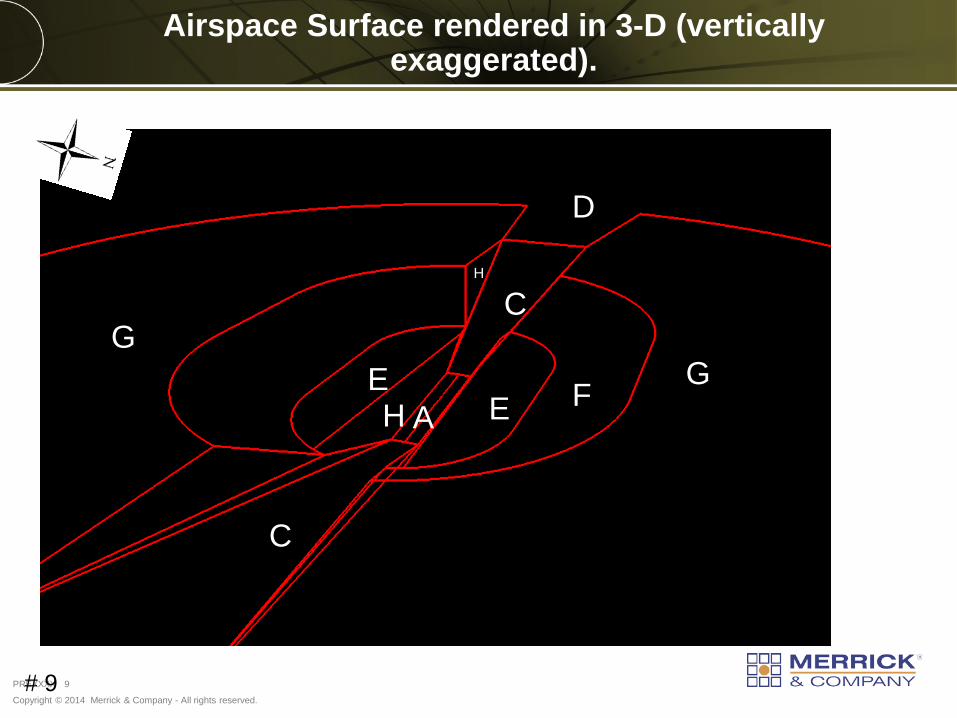
hazards to aircraft, aircrews, and ground personnel. Follow regulations stated specifically in UFC 3-260-01 Construct spatial 3D imaginary surfaces that follow the criteria of Class B Army Runway Airspace Imaginary Surfaces.
Class B Air Force and Navy Runway Imaginary Surfaces.
A – Primary Surface (304M (1,000 USFT Wide)
B – Clear Zone Surface (Not Shown)
C – Approach Departure Clearance Surface (Slope (50H:1V Ratio)
D – Approach-Departure Clearance Surface (Horizontal)
E – Inner Horizontal Surface (45.72M (105 USFT Elevation)
F – Conical Surface (20H:1V)
G – Outer Horizontal Surface (152.4M (500 USFT Elevation)
H- Transitional Surface (7H:1V)
I – Not used
J – Accidental Potential Zone (APZ) Not Shown

Copyright © 2014 Merrick & Company - All rights reserved.
PREXXXX 8
Obstruction Mapping Classifications of Obstructions Waiver – (permanent, temporary or construction) – An obstruction
that violates airspace per UFC 3-260-01 is temporary for construction (construction waiver), cannot be reasonably corrected (permanent), or is expected to be corrected within 5 years (temporary). Requests for waivers must present compelling justification to violate criteria and clearly demonstrate no viable, practical alternative that meets criteria exists.
Permissible Deviations - An obstruction required to support airfield operations that is not required to meet airfield clearance criteria that must meet siting criteria.
Exemption - An obstruction (facility or other item) constructed/sited under a previous, typically less stringent siting standard. No waiver is required. Facilities or other items constructed/sited under current standards that are behind and beneath a MAJCOM-approved Building Restriction Line (BRL) are considered exemptions and therefore do not require a waiver.
Copyright © 2014 Merrick & Company - All rights reserved.
PREXXXX 9
C
G
C
F
D
E E H A
G
H
Airspace Surface rendered in 3-D (vertically exaggerated).
# 9

Copyright © 2014 Merrick & Company - All rights reserved.
PREXXXX 10
Airspace Surface rendered in 3-D w/ Light Detection and Ranging (LiDAR) point cloud

Copyright © 2014 Merrick & Company - All rights reserved.
PREXXXX 11
C
Approach-Departure Clearance Surface (C) w/ obstructions identified using LiDAR
Features in violation of the geometric airfield

Copyright © 2014 Merrick & Company - All rights reserved.
PREXXXX 12
C
Approach-Departure Clearance Surface (C) w/ obstructions identified using LiDAR
Features in violation of the geometric airfield
Airspace Imaginary Surface (C)
Ground Above ground features, non-violation.
Obstructions above Airspace Imaginary Surface (C)

Copyright © 2014 Merrick & Company - All rights reserved.
PREXXXX 13
C
Airspace Imaginary Surface (C)
Ground Above ground features, non-violation.
Obstructions above Airspace Imaginary Surface (C)
Transmission Lines
Approach-Departure Clearance Surface (C) w/ obstructions identified using LiDAR (cont)

Copyright © 2014 Merrick & Company - All rights reserved.
PREXXXX 14
Relevant Map E Series E-1 - On-Installation Obstructions to Airfield Criteria. Specifically primary
surfaces and a specified clear zone.
E-2 - Approach/Departure Zone Obstructions to 10,000 ft from beginning of runway (glide angle).
E-3 - Approach/Departure Zone Obstructions from 10,000 ft to 10 miles (more for natural terrain hazards such as hills).
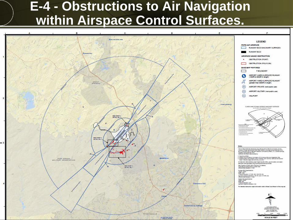
E-4 - Shows obstructions to air navigation (natural and man-made) within the airspace control surfaces.
E-5 - Terminal Enroute Procedures (TERPS) Automation Plan (highest feature in master obstacle chart).
E-6 - Airfield and Airspace Clearances.
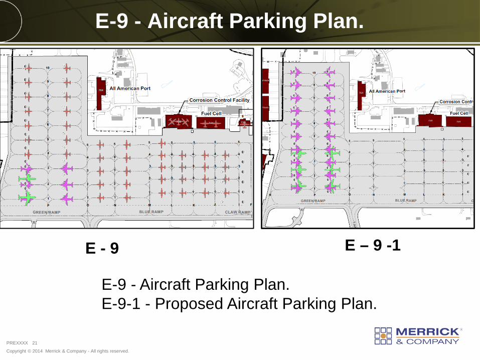
E-9 - Aircraft Parking Plan.
E-9-1 - Proposed Aircraft Parking Plan.
E-10 – Airfield Lighting System.

Copyright © 2014 Merrick & Company - All rights reserved.
PREXXXX 15
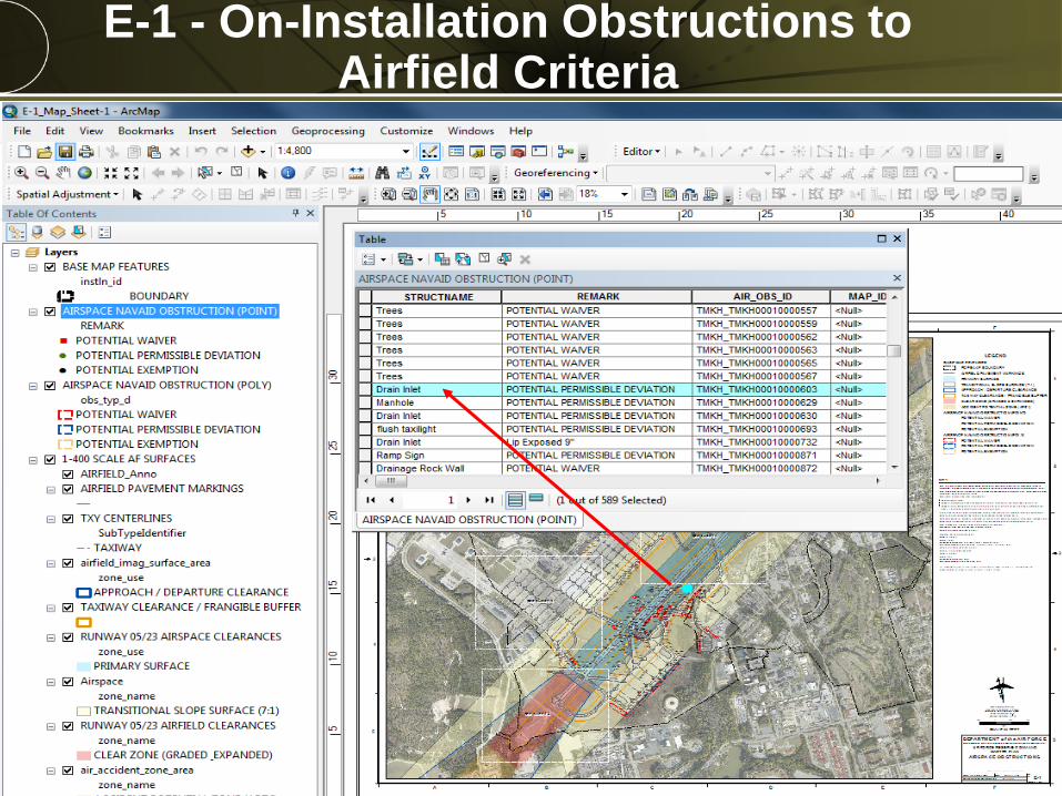
E-1 - On-Installation Obstructions to Airfield Criteria
All Features that impact the primary surface and specified clear zones.
Copyright © 2014 Merrick & Company - All rights reserved.
PREXXXX 16
E-1 - On-Installation Obstructions to Airfield Criteria

Copyright © 2014 Merrick & Company - All rights reserved.
PREXXXX 17
E-2 - Approach/Departure Zone Obstructions to 10,000 ft

Copyright © 2014 Merrick & Company - All rights reserved.
PREXXXX 18
E-3 - Approach/Departure Zone Obstructions from 10,000 ft to 10 miles
Copyright © 2014 Merrick & Company - All rights reserved.
PREXXXX 19
E-4 - Obstructions to Air Navigation within Airspace Control Surfaces.

Copyright © 2014 Merrick & Company - All rights reserved.
PREXXXX 20
E-5 - Terminal Enroute Procedures (TERPS) Automation Plan
E-5 Identifies highest feature is Master Obstacle Chart. Grid “Wagon Wheel” splays radiates from airport reference point and lists max z.
Copyright © 2014 Merrick & Company - All rights reserved.
PREXXXX 21
E-9 - Aircraft Parking Plan.
E - 9 E – 9 -1
E-9 - Aircraft Parking Plan. E-9-1 - Proposed Aircraft Parking Plan.

Copyright © 2014 Merrick & Company - All rights reserved.
PREXXXX 22
E-10 – Airfield Lighting System.

Copyright © 2014 Merrick & Company - All rights reserved.
PREXXXX 23
Conclusions
Lidar and Othropotography are instrumental for E-Tab series obstruction mapping.
Lidar and Othropotography assist with the both the pre-survey planning for obstruction mapping and post survey verification.
Spatial Analyst and Lidar analysis software are instrumental for detecting which features break the 3D imaginary surface plane.
Utilizing high resolution Lidar and Orhtopotography (complimented with the field survey) assist with classifying obstructions as waivers, permissible deviations or exemptions.
Mobile scanning is a viable alternative for primary surface (E1) obstruction collection.

Copyright © 2014 Merrick & Company - All rights reserved.
PREXXXX 24
Conclusions (Collection Methods)
Stationary Surface - Mobile
Helicopter Fixed-Wing

THANK YOU
Yaneev Golombek, GISP Merrick and Company
[email protected] PhD Student
University of Colorado