DOCUMENTATION BULLETINlaynercenter.ru/images/SB/L-410-UVP-E-247d.pdf · 2018-02-21 · SECTION 0 L...
28
Aircraft Industries, a.s. Kunovice 686 04 Czech Republic, tel.: +420 572 817 660, fax: +420 572 816 112, e-mail: [email protected] FQ050103D DOCUMENTATION BULLETIN DB No.: L410UVP-E/247d Concerns: Airplane Flight Manual for the L410 UVP-E20 with H80-200 Engines and AV-725 Propellers Doc. No. Do-L410-1218.2. Subject: Issue of the revision No. 5. Reason: Introduction of the procedure for BETA RANGE signalization. Measure: Replace pages in above Airplane Flight Manual by the enclosed new pages. To be carried out at the latest by: After the Bulletin receipt. To be carried out by: Holder of the above-mentioned document. Necessary material to be supplied by: Revision 5 of the AFM is enclosed to this bulletin. Bulletin becomes effective: On the date of its issue. Total number of pages: 1+13 ……………………………........ Released: Pavel Jurák Head of airworthiness dept. The technical content of this document is approved under the authority of DOA ref. EASA.21J.119. Issue date 15. 12. 2017
Transcript of DOCUMENTATION BULLETINlaynercenter.ru/images/SB/L-410-UVP-E-247d.pdf · 2018-02-21 · SECTION 0 L...
Aircraft Industries, a.s. Kunovice 686 04 Czech Republic, tel.: +420 572 817 660, fax: +420 572 816 112, e-mail: [email protected] FQ050103D
DOCUMENTATION BULLETIN
DB No.: L410UVP-E/247d
Concerns: Airplane Flight Manual for the L410 UVP-E20 with H80-200 Engines and AV-725 Propellers Doc. No. Do-L410-1218.2.
Subject: Issue of the revision No. 5.
Reason: Introduction of the procedure for BETA RANGE signalization.
Measure: Replace pages in above Airplane Flight Manual by the enclosed new pages.
To be carried out at the latest by: After the Bulletin receipt. To be carried out by: Holder of the above-mentioned document.
Necessary material to be supplied by: Revision 5 of the AFM is enclosed to this bulletin.
Bulletin becomes effective: On the date of its issue. Total number of pages: 1+13
……………………………........ Released: Pavel Jurák
Head of airworthiness dept.
The technical content of this document is approved under the authority of DOA ref. EASA.21J.119.
Issue date 15. 12. 2017

L 410 UVP-E20
with H80-200 engines & AV-725 propellers
FLIGHT MANUAL SECTION 0
Dec 12/17 (5) 0 – 1
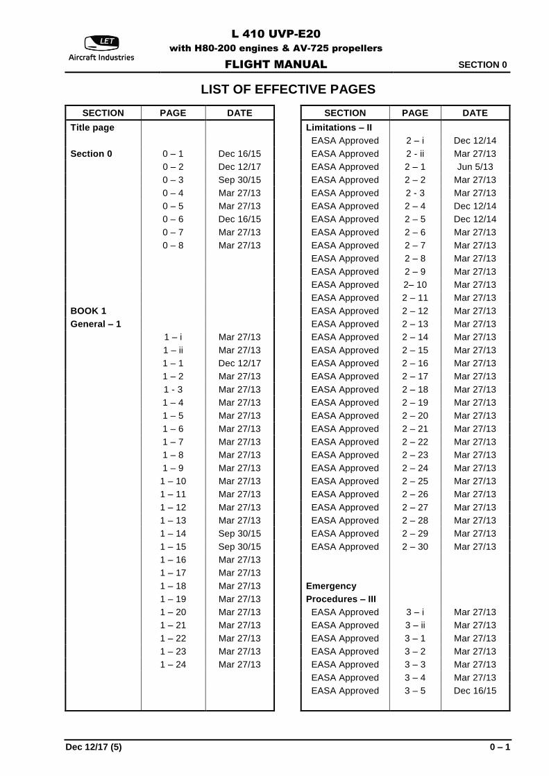
LIST OF EFFECTIVE PAGES
SECTION PAGE DATE
Title page
Section 0 0 – 1 Dec 16/15
0 – 2 Dec 12/17
0 – 3 Sep 30/15
0 – 4 Mar 27/13
0 – 5 Mar 27/13
0 – 6 Dec 16/15
0 – 7 Mar 27/13
0 – 8 Mar 27/13
BOOK 1
General – 1
1 – i Mar 27/13
1 – ii Mar 27/13
1 – 1 Dec 12/17
1 – 2 Mar 27/13
1 - 3 Mar 27/13
1 – 4 Mar 27/13
1 – 5 Mar 27/13
1 – 6 Mar 27/13
1 – 7 Mar 27/13
1 – 8 Mar 27/13
1 – 9 Mar 27/13
1 – 10 Mar 27/13
1 – 11 Mar 27/13
1 – 12 Mar 27/13
1 – 13 Mar 27/13
1 – 14 Sep 30/15
1 – 15 Sep 30/15
1 – 16 Mar 27/13
1 – 17 Mar 27/13
1 – 18 Mar 27/13
1 – 19 Mar 27/13
1 – 20 Mar 27/13
1 – 21 Mar 27/13
1 – 22 Mar 27/13
1 – 23 Mar 27/13
1 – 24 Mar 27/13
SECTION PAGE DATE
Limitations – II
EASA Approved 2 – i Dec 12/14
EASA Approved 2 - ii Mar 27/13
EASA Approved 2 – 1 Jun 5/13
EASA Approved 2 – 2 Mar 27/13
EASA Approved 2 - 3 Mar 27/13
EASA Approved 2 – 4 Dec 12/14
EASA Approved 2 – 5 Dec 12/14
EASA Approved 2 – 6 Mar 27/13
EASA Approved 2 – 7 Mar 27/13
EASA Approved 2 – 8 Mar 27/13
EASA Approved 2 – 9 Mar 27/13
EASA Approved 2– 10 Mar 27/13
EASA Approved 2 – 11 Mar 27/13
EASA Approved 2 – 12 Mar 27/13
EASA Approved 2 – 13 Mar 27/13
EASA Approved 2 – 14 Mar 27/13
EASA Approved 2 – 15 Mar 27/13
EASA Approved 2 – 16 Mar 27/13
EASA Approved 2 – 17 Mar 27/13
EASA Approved 2 – 18 Mar 27/13
EASA Approved 2 – 19 Mar 27/13
EASA Approved 2 – 20 Mar 27/13
EASA Approved 2 – 21 Mar 27/13
EASA Approved 2 – 22 Mar 27/13
EASA Approved 2 – 23 Mar 27/13
EASA Approved 2 – 24 Mar 27/13
EASA Approved 2 – 25 Mar 27/13
EASA Approved 2 – 26 Mar 27/13
EASA Approved 2 – 27 Mar 27/13
EASA Approved 2 – 28 Mar 27/13
EASA Approved 2 – 29 Mar 27/13
EASA Approved 2 – 30 Mar 27/13
Emergency
Procedures – III
EASA Approved 3 – i Mar 27/13
EASA Approved 3 – ii Mar 27/13
EASA Approved 3 – 1 Mar 27/13
EASA Approved 3 – 2 Mar 27/13
EASA Approved 3 – 3 Mar 27/13
EASA Approved 3 – 4 Mar 27/13
EASA Approved 3 – 5 Dec 16/15
SECTION 0
L 410 UVP-E20
with H80-200 engines & AV-725 propellers
FLIGHT MANUAL
0 – 2 (5) Dec 12/17
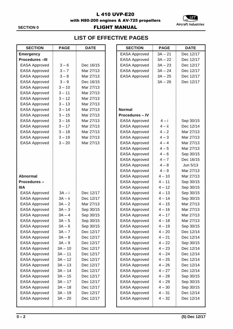
LIST OF EFFECTIVE PAGES
SECTION PAGE DATE
Emergency
Procedures –III
EASA Approved 3 – 6 Dec 16/15
EASA Approved 3 – 7 Mar 27/13
EASA Approved 3 – 8 Mar 27/13
EASA Approved 3 – 9 Dec 16/15
EASA Approved 3 – 10 Mar 27/13
EASA Approved 3 – 11 Mar 27/13
EASA Approved 3 – 12 Mar 27/13
EASA Approved 3 – 13 Mar 27/13
EASA Approved 3 – 14 Mar 27/13
EASA Approved 3 – 15 Mar 27/13
EASA Approved 3 – 16 Mar 27/13
EASA Approved 3 – 17 Mar 27/13
EASA Approved 3 – 18 Mar 27/13
EASA Approved 3 – 19 Mar 27/13
EASA Approved 3 – 20 Mar 27/13
Abnormal
Procedures –
IIIA
EASA Approved 3A – i Dec 12/17
EASA Approved 3A – ii Dec 12/17
EASA Approved 3A – 2 Mar 27/13
EASA Approved 3A – 3 Sep 30/15
EASA Approved 3A – 4 Sep 30/15
EASA Approved 3A – 5 Sep 30/15
EASA Approved 3A – 6 Sep 30/15
EASA Approved 3A – 7 Dec 12/17
EASA Approved 3A – 8 Dec 12/17
EASA Approved 3A – 9 Dec 12/17
EASA Approved 3A – 10 Dec 12/17
EASA Approved 3A – 11 Dec 12/17
EASA Approved 3A – 12 Dec 12/17
EASA Approved 3A – 13 Dec 12/17
EASA Approved 3A – 14 Dec 12/17
EASA Approved 3A – 15 Dec 12/17
EASA Approved 3A – 17 Dec 12/17
EASA Approved 3A – 18 Dec 12/17
EASA Approved 3A – 19 Dec 12/17
EASA Approved 3A – 20 Dec 12/17
SECTION PAGE DATE
EASA Approved 3A – 21 Dec 12/17
EASA Approved 3A – 22 Dec 12/17
EASA Approved 3A – 23 Dec 12/17
EASA Approved 3A – 24 Dec 12/17
EASA Approved 3A – 25 Dec 12/17
3A – 26 Dec 12/17
Normal
Procedures – IV
EASA Approved 4 – i Sep 30/15
EASA Approved 4 – ii Dec 12/14
EASA Approved 4 – 2 Mar 27/13
EASA Approved 4 – 3 Mar 27/13
EASA Approved 4 – 4 Mar 27/13
EASA Approved 4 – 5 Mar 27/13
EASA Approved 4 – 6 Sep 30/15
EASA Approved 4 – 7 Dec 16/15
EASA Approved 4 – 8 Jun 5/13
EASA Approved 4 – 9 Mar 27/13
EASA Approved 4 – 10 Mar 27/13
EASA Approved 4 – 11 Sep 30/15
EASA Approved 4 – 12 Sep 30/15
EASA Approved 4 – 13 Sep 30/15
EASA Approved 4 – 14 Sep 30/15
EASA Approved 4 – 15 Mar 27/13
EASA Approved 4 – 16 Mar 27/13
EASA Approved 4 – 17 Mar 27/13
EASA Approved 4 – 18 Mar 27/13
EASA Approved 4 – 19 Sep 30/15
EASA Approved 4 – 20 Dec 12/14
EASA Approved 4 – 21 Dec 12/14
EASA Approved 4 – 22 Sep 30/15
EASA Approved 4 – 23 Dec 12/14
EASA Approved 4 – 24 Dec 12/14
EASA Approved 4 – 25 Dec 12/14
EASA Approved 4 – 26 Dec 12/14
EASA Approved 4 – 27 Dec 12/14
EASA Approved 4 – 28 Sep 30/15
EASA Approved 4 – 29 Sep 30/15
EASA Approved 4 – 30 Sep 30/15
EASA Approved 4 – 31 Dec 12/14
EASA Approved 4 – 32 Dec 12/14
L 410 UVP-E20
with H80-200 engines & AV-725 propellers
FLIGHT MANUAL SECTION I
GENERAL
Mar 27/13 1 - 1
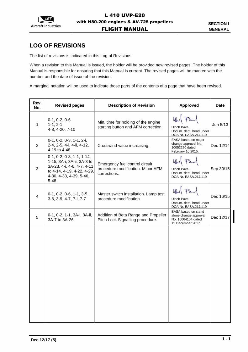
LOG OF REVISIONS
The list of revisions is indicated in this Log of Revisions.
When a revision to this Manual is issued, the holder will be provided new revised pages. The holder of this
Manual is responsible for ensuring that this Manual is current. The revised pages will be marked with the
number and the date of issue of the revision.
A marginal notation will be used to indicate those parts of the contents of a page that have been revised.
Rev. No.
Revised pages Description of Revision Approved Date
1 0-1, 0-2, 0-6 1-1, 2-1 4-8, 4-20, 7-10
Min. time for holding of the engine starting button and AFM correction.
Ulrich Pavel Docum. dept. head under DOA Nr. EASA.21J.119
Jun 5/13
2
0-1, 0-2, 0-3, 1-1, 2-i, 2-4, 2-5, 4-i, 4-ii, 4-12, 4-19 to 4-48
Crosswind value increasing.
EASA based on major change approval No. 10052220 dated February 10 2015.
Dec 12/14
3
0-1, 0-2, 0-3, 1-1, 1-14, 1-15, 3A-i, 3A-ii, 3A-3 to 3A-23, 4-i, 4-6, 4-7, 4-11 to 4-14, 4-19, 4-22, 4-29, 4-30, 4-33, 4-39, 5-46, 5-48
Emergency fuel control circuit procedure modification. Minor AFM corrections.
Ulrich Pavel Docum. dept. head under DOA Nr. EASA.21J.119
Sep 30/15
4 0-1, 0-2, 0-6, 1-1, 3-5, 3-6, 3-9, 4-7, 7-i, 7-7
Master switch installation. Lamp test procedure modification.
Ulrich Pavel Docum. dept. head under DOA Nr. EASA.21J.119
Dec 16/15
5 0-1, 0-2, 1-1, 3A-i, 3A-ii, 3A-7 to 3A-26
Addition of Beta Range and Propeller Pitch Lock Signalling procedure.
EASA based on stand alone change approval No. 10064104 dated 15 December 2017
Dec 12/17
Dec 12/17 (5)
SECTION I
GENERAL
L 410 UVP-E20
with H80-200 engines & AV-725 propellers
FLIGHT MANUAL
1 - 2 Mar 27/13
Rev. No.
Revised pages Description of Revision Approved Date
L410 UVP-E20
with H80-200 engines & AV-725 propellers
FLIGHT MANUAL
SECTION IIIA
ABNORMAL PROCEDURES
Dec 12/17 (5) EASA APPROVED 3A - i
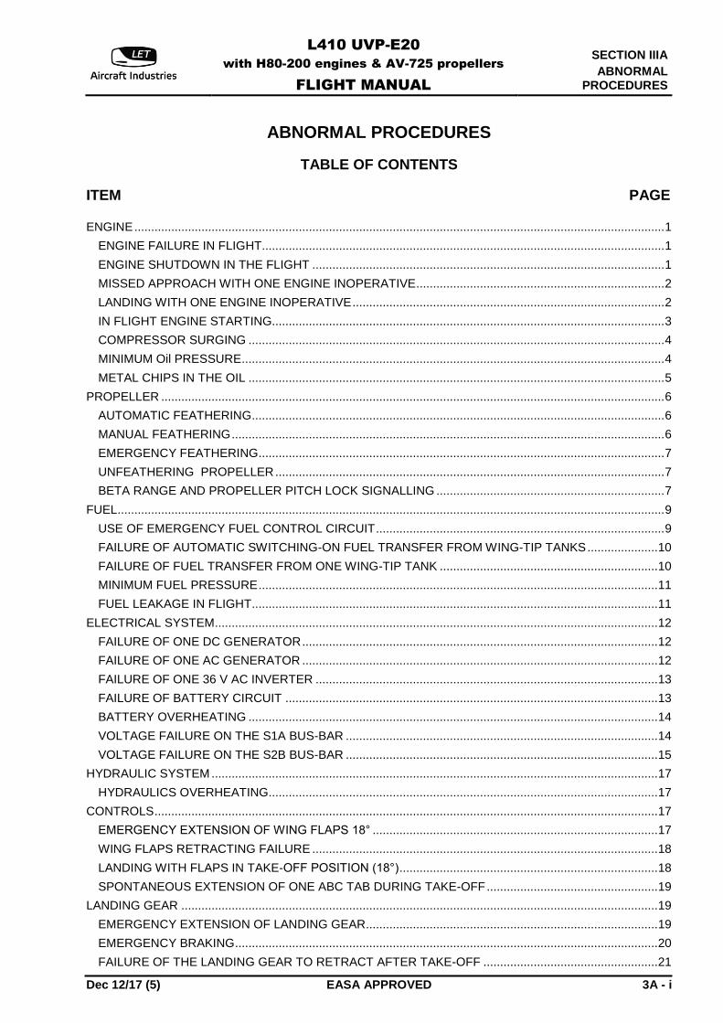
ABNORMAL PROCEDURES
TABLE OF CONTENTS
ITEM PAGE
ENGINE .............................................................................................................................................................. 1
ENGINE FAILURE IN FLIGHT........................................................................................................................ 1
ENGINE SHUTDOWN IN THE FLIGHT ......................................................................................................... 1
MISSED APPROACH WITH ONE ENGINE INOPERATIVE .......................................................................... 2
LANDING WITH ONE ENGINE INOPERATIVE ............................................................................................. 2
IN FLIGHT ENGINE STARTING..................................................................................................................... 3
COMPRESSOR SURGING ............................................................................................................................ 4
MINIMUM Oil PRESSURE .............................................................................................................................. 4
METAL CHIPS IN THE OIL ............................................................................................................................ 5
PROPELLER ...................................................................................................................................................... 6
AUTOMATIC FEATHERING ........................................................................................................................... 6
MANUAL FEATHERING ................................................................................................................................. 6
EMERGENCY FEATHERING ......................................................................................................................... 7
UNFEATHERING PROPELLER .................................................................................................................... 7
BETA RANGE AND PROPELLER PITCH LOCK SIGNALLING .................................................................... 7
FUEL ................................................................................................................................................................... 9
USE OF EMERGENCY FUEL CONTROL CIRCUIT ...................................................................................... 9
FAILURE OF AUTOMATIC SWITCHING-ON FUEL TRANSFER FROM WING-TIP TANKS ..................... 10
FAILURE OF FUEL TRANSFER FROM ONE WING-TIP TANK ................................................................. 10
MINIMUM FUEL PRESSURE ....................................................................................................................... 11
FUEL LEAKAGE IN FLIGHT ......................................................................................................................... 11
ELECTRICAL SYSTEM .................................................................................................................................... 12
FAILURE OF ONE DC GENERATOR .......................................................................................................... 12
FAILURE OF ONE AC GENERATOR .......................................................................................................... 12
FAILURE OF ONE 36 V AC INVERTER ...................................................................................................... 13
FAILURE OF BATTERY CIRCUIT ............................................................................................................... 13
BATTERY OVERHEATING .......................................................................................................................... 14
VOLTAGE FAILURE ON THE S1A BUS-BAR ............................................................................................. 14
VOLTAGE FAILURE ON THE S2B BUS-BAR ............................................................................................. 15
HYDRAULIC SYSTEM ..................................................................................................................................... 17
HYDRAULICS OVERHEATING.................................................................................................................... 17
CONTROLS ...................................................................................................................................................... 17
EMERGENCY EXTENSION OF WING FLAPS 18° ..................................................................................... 17
WING FLAPS RETRACTING FAILURE ....................................................................................................... 18
LANDING WITH FLAPS IN TAKE-OFF POSITION (18°) ............................................................................. 18
SPONTANEOUS EXTENSION OF ONE ABC TAB DURING TAKE-OFF ................................................... 19
LANDING GEAR .............................................................................................................................................. 19
EMERGENCY EXTENSION OF LANDING GEAR....................................................................................... 19
EMERGENCY BRAKING .............................................................................................................................. 20
FAILURE OF THE LANDING GEAR TO RETRACT AFTER TAKE-OFF .................................................... 21
SECTION IIIA
ABNORMAL PROCEDURES
L410 UVP-E20
with H80-200 engines & AV-725 propellers
FLIGHT MANUAL
3A – ii EASA APPROVED (5) Dec 12/17
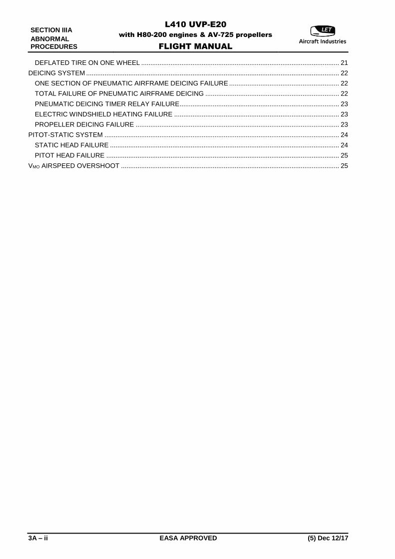
DEFLATED TIRE ON ONE WHEEL ............................................................................................................ 21
DEICING SYSTEM .......................................................................................................................................... 22
ONE SECTION OF PNEUMATIC AIRFRAME DEICING FAILURE ............................................................ 22
TOTAL FAILURE OF PNEUMATIC AIRFRAME DEICING ......................................................................... 22
PNEUMATIC DEICING TIMER RELAY FAILURE ....................................................................................... 23
ELECTRIC WINDSHIELD HEATING FAILURE .......................................................................................... 23
PROPELLER DEICING FAILURE ............................................................................................................... 23
PITOT-STATIC SYSTEM ................................................................................................................................ 24
STATIC HEAD FAILURE ............................................................................................................................. 24
PITOT HEAD FAILURE ............................................................................................................................... 25
VMO AIRSPEED OVERSHOOT ....................................................................................................................... 25
L410 UVP-E20
with H80-200 engines & AV-725 propellers
FLIGHT MANUAL
SECTION IIIA
ABNORMAL PROCEDURES
Dec 12/17 (5) EASA APPROVED 3A - 7
NOTE
During straight and level flight a feathered propeller may turn at not
more than 50 RPM in the direction of engine shaft rotation, and not
more than 20 RPM in the opposite direction.
EMERGENCY FEATHERING
If the propeller blades are not feathered 5 seconds after the MANUAL FEATHERING button has been
pushed, move the PCL of the stopped engine back to its rearmost, "Feathered", position.
The blades will in this case take max. 20 seconds to reach feathered position.
UNFEATHERING PROPELLER
TCL ................................................................................................. IDLE position
PCL ................................................................................................. initial FEATHER position
PROP FEATHERING/AUT. BANK CONTROL circuit breaker ................................................................................. OFF and ON again
PCL ................................................................................................. FINE PITCH
NOTE
If the propeller unfeathering does not occur and nP stabilizes at
approximately 350 RPM, slowly increase nG until nP starts rising, but to
80% at the most.
BETA RANGE AND PROPELLER PITCH LOCK SIGNALLING
a) On final approach
When the amber BETA RANGE cell (in the Engine section of the CWD) comes on perform the following
procedure on the affected engine:
TCL .............................................................................................................. IDLE
MANUAL FEATHER push-button (under cover) ........................................ PUSH
After manual feathering and also if propeller has not been feathered:
PCL......................................................................................................... FEATHER
SECTION IIIA
ABNORMAL PROCEDURES
L410 UVP-E20
with H80-200 engines & AV-725 propellers
FLIGHT MANUAL
3A – 8 EASA APPROVED (5) Dec 12/17
b) During take-off
When the amber BETA RANGE cell (in the Engine section of the CWD) comes on:
Below V1 ..................................................................................................... abort take-off
Above V1:
ELU LH, RH ................................................................................................. switch off
TAKE-OFF ................................................................................................... complete take-off
After take-off completing follow procedure c).
c) During other phases of the flight
When the amber BETA RANGE cell (in the Engine section of the CWD) comes on but amber
PROPELLER PITCH LOCK cell does not come on, it is false signaling.
ELU LH, RH ......................................................................................... switch off
No further action is required.
When the amber BETA RANGE cell (in the Engine section of the CWD) and amber PROPELLER PITCH
LOCK cell come on:
ELU LH, RH ......................................................................................... switch off
Flight. ................................................................................................... continue
CAUTION
ANY POWER REDUCTION UNDER 80 % NG CAN CAUSE
A DIFFERENCE IN PROPELLERS SPEEDS, I.E. A THRUST
ASYMMETRY.
Before descent, for affected engine:
TCL ...................................................................................................... IDLE
MANUAL FEATHER push-button (under cover) ................................. PUSH
After manual feathering and also if propeller has not been feathered:
PCL ................................................................................................. FEATHER
Engine .................................................................................................. SHUT DOWN
Complete flight with one engine inoperative.
L410 UVP-E20
with H80-200 engines & AV-725 propellers
FLIGHT MANUAL
SECTION IIIA
ABNORMAL PROCEDURES
Dec 12/17 (5) EASA APPROVED 3A - 9
FUEL
USE OF EMERGENCY FUEL CONTROL CIRCUIT
The emergency fuel control circuit controls the engine in case of a normal fuel control system failure which is indicated by nG hang-up, or a spontaneous increase in nG, or a spontaneous drop of engine power the engine will not respond to movements of the TCL, or responds abnormally.
WARNING
BETA CONTROL AND REVERSE PITCH MUST NOT BE
ENGAGED WHEN THE EMERGENCY CIRCUIT IS IN USE.
CAUTION
1. THE EMERGENCY CIRCUIT CAN BE USED ONLY WHEN THE
FUEL PUMP OF THE AFFECTED ENGINE IS FUNCTIONING
NORMALLY.
2. USING OF THE EMERGENCY CIRCUIT IS ALLOWED ONLY IN
CASE OF NORMAL FUEL CONTROL SYSTEM FAILURE FOR
COMPLETION OF FLIGHT ONLY.
ANY FURTHER AIRPLANE OPERATION WITH FUEL
CONTROL SYSTEM FAILURE AND EMERGENCY CIRCUIT
USING INSTEAD IS FORBIDDEN.
NOTE
1. Before switching-on, the emergency fuel control circuit switch-off
the automatic feathering.
2. Engagement of the emergency fuel control circuit automatically
disconnects the system which controls the fuel supply regulator,
as well as the automatic engine starting cycle, the minimum fuel
consumption valve which safeguards idling speed at higher
altitudes, and limiter system function (except engine parameter
exceeding signaling).Therefore, when this circuit is engaged, a
check must be kept (especially during altitude changes) on the
key parameters of the engine (nG, ITT and TQ) to ensure that
none of them exceeds the permissible maximum limits (for service
limitations, see Section 2). At the same time, the nG must not be
allowed to fall below 60% at altitudes lower than 6,500 ft (2,000
m), or below 70% at altitudes above 6,500 ft (2,000 m).
3. At altitudes below 6,500 ft (2,000 m) the gas generator may fail to
reach its maximum speed (99%) even when the Fuel stop
cock/Emergency throttle lever is set to its foremost position.

SECTION IIIA
ABNORMAL PROCEDURES
L410 UVP-E20
with H80-200 engines & AV-725 propellers
FLIGHT MANUAL
3A – 10 EASA APPROVED (5) Dec 12/17
(a) Engaging the emergency fuel control circuit TCL .......................................................................................................IDLE
Fuel stop cock/Emergency throttle lever ..............................................Check OPEN position
ISOL. VALVE circuit breaker ................................................................ON ISOLATION VALVE amber cell on the CWD
of the affected engine ...........................................................................Check ON
Fuel stop cock/Emergency throttle lever ..............................................Move slowly forward from OPEN position to emergency circuit area to set minimum nG
Set required power rating by slow displacement (min. 6 sec) of the Fuel stop cock/Emergency throttle lever within the range of the OPEN position and the MAX. POWER position.
(b) Stopping an engine with the emergency circuit engaged
The sequence of steps is the same as in the normal engine stopping procedure - see Section 4.
NOTE
Each Emergency Circuit Usage for completion of flight mission has to
be reported to GEAC Customer Support Service prior to next flight
with description of event for further instruction and recorded in to
Engine Log Book and FCU Record Form.
FAILURE OF AUTOMATIC SWITCHING-ON FUEL TRANSFER FROM WING-TIP TANKS
This failure is indicated by amber ACTUATE TRANSFER cell (RH or LH) in the Airframe section of the CWD.
WING TIP TANK FUEL TRANSFER switch for the affected side on the right instrument panel .............................ON
Green FUEL TRANSFER cell in the Airframe section of the CWD ....................................................CHECK ON
FAILURE OF FUEL TRANSFER FROM ONE WING-TIP TANK
NOTE
If fuel transfer fails from one wing-tip tank it is possible to use the fuel
from the other tip tank.
Aileron control is sufficient to maintain flight without bank in all configurations and required steering column deflection does not exceed the half of available range.
L410 UVP-E20
with H80-200 engines & AV-725 propellers
FLIGHT MANUAL
SECTION IIIA
ABNORMAL PROCEDURES
Dec 12/17 (5) EASA APPROVED 3A - 11
MINIMUM FUEL PRESSURE
This is indicated by amber FUEL PRESSURE cell in the Engine section of the CWD.
NOTE
The reason for the fuel pressure drop is either failure of the fuel pump
or full utilization of fuel in the group of tanks in use.
- Check that the FUEL PUMP LH (RH) circuit breaker on the overhead panel is switched-on. - Check the MINIMUM FUEL signal. - Check the fuel quantity in the group of tank in use. If necessary use cross feed. - If you are in the flight level above 13,000 ft (4,000 m) descend below 13,000 ft (4,000 m) - Check the fuel pressure on the three-pointer indicator. The pointer must indicate in the green sector
(0.5 to 12 kp/cm2). If previous instructions have been executed and the engine works normally then continue the flight and pay closely attention to the main parameters of the engine. If the engine operates irregularly: TCL of the faulty engine .................................................................. IDLE Engine shutdown in flight (see page 3A-1) ............................................. CARRY-OUT
FUEL LEAKAGE IN FLIGHT
Fuel leakage from a fuel tank filler cap which is not closed properly can be detected by the fuel mist that forms behind the trailing edge of the wing, and by fuel content in affected tanks changes faster than the contents of the other tanks. The fuel mist is visible only from the rear windows of the passenger cabin. (a) If fuel leakage is observed soon after take-off: - Return to airport of departure. Do not utilize fuel transfer system. (b) If leakage is observed on route: - Check how much fuel is left in tanks. Depending on the fuel reserve, decide whether to continue to the nearest airport or whether to carry out an emergency landing. Feed both engines with fuel from the tanks on the leaking side, by the procedure fuel crossfeed - see section 4. Continue using fuel only from the leaking side, after the MINIMUM FUEL cell has come on, switch over to fuel crossfeed from the opposite group of fuel tanks.
SECTION IIIA
ABNORMAL PROCEDURES
L410 UVP-E20
with H80-200 engines & AV-725 propellers
FLIGHT MANUAL
3A – 12 EASA APPROVED (5) Dec 12/17
ELECTRICAL SYSTEM
FAILURE OF ONE DC GENERATOR
This failure is indicated by amber DC GENERATOR (LH or RH) cell in the Electro section of the CWD. Check the switches on the overhead panel to confirm that this is not a false alarm. DC GENERATOR switch of failed unit .............................................. OFF and then back ON again If DC GENERATOR is fault: DC GENERATOR switch of failed unit .............................................. OFF VA METER selector switch on the INVERTER SELECTION panel .................................................................................................. Set first to BATTERY I VA and then to BATTERY II VA position Check the charging rate on the right volt/ammeter.
FAILURE OF ONE AC GENERATOR
This failure is indicated by amber AC GENERATOR (LH or RH) cell in the Electro section of the CWD. Check the switches on the overhead panel to confirm that this is not a false alarm. AC GENERATOR switch of failed unit ......................................... OFF and then back ON again If AC GENERATOR is fault: AC GENERATOR switch of failed unit ......................................... OFF
NOTE
The load on the failed AC generator is automatically transferred to the
other AC generator.
L410 UVP-E20
with H80-200 engines & AV-725 propellers
FLIGHT MANUAL
SECTION IIIA
ABNORMAL PROCEDURES
Dec 12/17 (5) EASA APPROVED 3A - 13
FAILURE OF ONE 36 V AC INVERTER
This failure is indicated by amber INVERTER 36 V AC (I or II) cell in the Electro section of the CWD. INVERTER 36V AC (I or II) switches on the overhead panel ............ CHECK ON INVERTER 36V AC (I or II) switches on the overhead panel ............ OFF and then back ON again If 36 V AC INVERTER is fault: Failed inverter switch ......................................................................... OFF
NOTE
1. All circuits previously fed by the failed inverter are automatically
switched over to the other inverter.
2. The amber INVERTER 36V AC (I or II) cell will not go off after the
faulty inverter has been switched off.
FAILURE OF BATTERY CIRCUIT
This failure is indicated by amber BATTERY cell in the Electro section of the CWD.
BATTERY switches on the overhead panel ...................................... CHECK ON
VA METER selector switch on the inverter selection panel .............. Set successively to BATTERY I VA and II VA
Charging of both batteries ................................................................. CHECK
BATTERY switch for the battery which is not charged...................... SWITCH OFF
CAUTION
THE BATTERY SIGNAL CELL WILL NOT GO OFF AFTER THE
FAULTY BATTERY HAS BEEN SWITCHED OFF.
SECTION IIIA
ABNORMAL PROCEDURES
L410 UVP-E20
with H80-200 engines & AV-725 propellers
FLIGHT MANUAL
3A – 14 EASA APPROVED (5) Dec 12/17
BATTERY OVERHEATING
NOTE
In case of battery overheating a red warning light comes on. The
warning lights are located on LH side of the glareshield of the
instrument panel.
If the red warning light comes on: BATTERY I (II) switch ........................................................................ OFF
NOTE
If the BATTERY I, II switches are in OFF position, you can continue in
flight. After landing report the failure to the ground staff.
VOLTAGE FAILURE ON THE S1A BUS-BAR
No voltage on the S1A bus-bar is indicated by the following instruments being out of service:
(a) ADF I (b) Transponder I (c) RH artificial horizon (d) RH turn-and-bank indicator (e) Internal instrument illumination (f) 36 V AC inverter I (g) Feathering pump left and right (h) Landing gear control - basic circuit (i) Nose wheel steering systems (j) Landing gear position indicator (k) Wing flaps position indicator (l) LH ENGINE AND AIRFRAME CWD panel (m) Instrument panel lighting, circuit II (n) LH engine oil temperature indicator (o) Center landing and taxiing searchlight
L410 UVP-E20
with H80-200 engines & AV-725 propellers
FLIGHT MANUAL
SECTION IIIA
ABNORMAL PROCEDURES
Dec 12/17 (5) EASA APPROVED 3A - 15
(p) LH wing tip tank fuel indicator (q) LH fuel gauge (r) Windshield deicing indication (s) Rudder trim and aileron trim tab controls (t) Indication of the air temperature in the heating duct and in the cabin (u) RH AC generator
INSTRUMENT PANEL/STBY CIRCUIT circuit breaker (at night) ............. ON I-SSR-II change-over switch (if installed) .................................................. position II
NOTE
1. Extend landing gear by means of the emergency system.
2. Check the extension by the mechanical indicators on the landing
gear nacelles and on the central control panel in the cockpit.
3. Keep directional control during landing by alternate braking, if
necessary also by means of alternate reverse power.
4. If transponder II is not installed, inform ATC about transponder
failure
VOLTAGE FAILURE ON THE S2B BUS-BAR
No voltage on the S2B bus-bar is indicated by the following instruments being out of service:
(a) NAV I or GPS I (according to specific installation) (b) VHF I (c) Gyro compass I (d) Intercom I (e) LH artificial horizon (f) Standby artificial horizon (g) LH turn-and-bank indicator (h) RH engine oil temperature indicator (i) 115 V AC inverter I (if installed) (j) Standby lighting of the instrument panels
SECTION IIIA
ABNORMAL PROCEDURES
L410 UVP-E20
with H80-200 engines & AV-725 propellers
FLIGHT MANUAL
3A – 16 EASA APPROVED (5) Dec 12/17
(k) Passengers cabin lighting 1/3 (l) FASTEN SEAT BELTS sign. (m) PITOT PRESSURE I and STATIC PRESSURE I heating (n) ELECTRO and R.H. ENGINE CWD panels (o) Signalization of engine fire (p) Automatic and manual feathering (LH and RH)/ Automatic bank control (LH and RH) (q) RH fuel gauge (r) RH tip tank fuel indicator (s) Front baggage compartment fire sign. (t) LH AC GENERATOR
PITOT PRESSURE II heating push-button on the RH control panel .............................................................................Check whether switched on and check proper function of heating element PITOT PRESSURE cock on the LH control panel .....................................Position II
NOTE
Instruct the passengers to fasten seat belts using the passenger
address system.
L410 UVP-E20
with H80-200 engines & AV-725 propellers
FLIGHT MANUAL
SECTION IIIA
ABNORMAL PROCEDURES
Dec 12/17 (5) EASA APPROVED 3A - 17
HYDRAULIC SYSTEM
HYDRAULICS OVERHEATING
If the amber HYDRAUL. cell (temperature of the hydraulic fluid is higher then 90°C) in the Engine section of the CWD light on:
- continue the flight, - check pressure in the hydraulic system - extend and retract twice landing gear to cool hydraulic fluid (observe VLE speed)
When cell HYDRAULIC remains on, land on the nearest suitable airport and inform ground staff. During operation in hot conditions (temperature range from 40°C to 50°C) it is recommended to perform flights above FL 060 to avoid overtemperature of hydraulic fluid.
CONTROLS
EMERGENCY EXTENSION OF WING FLAPS 18°
WING FLAPS control lever ................................................................... 18°
WING FLAPS EMERGENCY EXTENSION lever ................................ DOWN (OPEN)
Emergency hydraulic pump .................................................................. pump until appropriate indication on
wing flaps position indicator comes on
CAUTION
1. IF WING FLAPS EXTENSION SYSTEM FAILS, LAND WITH THE
WING FLAPS EXTENDED TO 18° ONLY. MAINTAIN THE
AIRSPEED OF 90 KIAS (167 km/hr IAS) UNTIL YOU PASS OVER
THE RUNWAY THRESHOLD AND REACH THE HEIGHT OF 50
FT (15 m) ABOVE THE RUNWAY.
2. IF IT IS NECESSARY TO EMERGENCY EXTEND THE FLAPS
AND LANDING GEAR THEN EXTEND LANDING GEAR FIRST.
NOTE
1. The wing flaps emergency extension lever is safety wired. Moving it
down to extend the wing flaps breaks the wire.
2. Emergency extension of the flaps to the 18 degree position requires
about 8 manual pumping strokes.
SECTION IIIA
ABNORMAL PROCEDURES
L410 UVP-E20
with H80-200 engines & AV-725 propellers
FLIGHT MANUAL
3A – 18 EASA APPROVED (5) Dec 12/17
WING FLAPS RETRACTING FAILURE
The failure is indicated by constant signalization of flap position 18° even if the flap position selector has been moved to the position 0° after take-off.
Real position of the flaps CHECK If the flaps have remained in the take-off position (18°):
Maintain climb with airspeed 124 KIAS (230 km/hr IAS) After climbing maintain the airspeed not exceeding 135 KIAS (250 km/hr IAS). Recommended value of airspeed is 108 KIAS (200 km/hr IAS).
According to your decision ........................................................................ Continue in the flight
NOTE
The fuel consumption at the airspeed of 108 KIAS (200 km/hr IAS) at
the altitude of 10,000 ft (3,000 m) is 230 kg/hr (507 lb/hr).
LANDING WITH FLAPS IN TAKE-OFF POSITION (18°)
At a height of 50 ft (15 m) above runway:
Flaps .......................................................................................................... 18° Airspeed ..................................................................................................... VREF 18 KIAS TCL ............................................................................................................ IDLE At the height of 10 ft (3 m) above runway: Airplane ...................................................................................................... FLARE Vertical speed ............................................................................................ 200 to 100 fpm (1 to 0.5 m/s) Immediately after touch-down according to conditions: Push-button of spoilers .............................................................................. PUSH and HOLD
NOTE
Spoilers can be controlled only by left pilot.
After nose-wheel touch down Brakes ........................................................................................................ APPLY TCL ............................................................................................................ REVERSE RATING as required Below airspeed of approx. 30 KIAS Push-button of spoilers .............................................................................. RELEASE
L410 UVP-E20
with H80-200 engines & AV-725 propellers
FLIGHT MANUAL
SECTION IIIA
ABNORMAL PROCEDURES
Dec 12/17 (5) EASA APPROVED 3A - 19
SPONTANEOUS EXTENSION OF ONE ABC TAB DURING TAKE-OFF
Extension of a tab tends to bank the airplane.
The airplane .......................................................................................... Level by means of the ailerons
AUT. BANK CONTROL switch on the central control panel .................................................................. OFF
If the ABC tab retracts: Further flight ......................................................................................... Continue If the ABC tab does not retract, trim the airplane using the aileron trim and do not exceed 111 KIAS (205 km/hr IAS). Decide whether to continue the flight or to land on the airport of departure. The fuel consumption at 108 KIAS (200 km/hr IAS) at the altitude of 10,000 ft (3,000 m) is 230 kg/hr (507 lb/hr).
LANDING GEAR
EMERGENCY EXTENSION OF LANDING GEAR
LANDING GEAR lever ......................................................................... DOWN position
LANDING GEAR EMERGENCY EXTENSION lever ........................... down
Emergency hydraulic pump .................................................................. Pump until the 3 green lights on
landing gear position indicator come on and until resistance on pump handle increases.
NOTE
1. The landing gear emergency extension lever is safety wired.
Moving it down to extend the landing gear, breaks the wire.
2. Emergency extension of the landing gear requires about 60 manual
pumping strokes. Time to landing gear extension is about 60 seconds.
If after the use of emergency hydraulic system some of the landing gear legs are stuck in the intermediate position (red light on the landing gear position indicator stays on) perform the following procedure:
Increase the airplane airspeed in horizontal flight to ............................ 135 KIAS (250 km/hr IAS)
Climb .................................................................................................... to safe altitude
Wait ...................................................................................................... 60 seconds
Sideslip ................................................................................................. Perform
Smoothly push the rudder to the side of the stuck landing gear leg while maintaining the flight direction
with ailerons. Maintain the rudder deflection until securing the landing gear leg in its locked down position
and/or until reaching the maximum rudder deflection. Bank angle during this manoeuvre must not exceed
20°. Keep the maximum rudder deflection for a period of 10 seconds.
SECTION IIIA
ABNORMAL PROCEDURES
L410 UVP-E20
with H80-200 engines & AV-725 propellers
FLIGHT MANUAL
3A – 20 EASA APPROVED (5) Dec 12/17
If locking of the landing gear leg does not take place:
Sideslip .................................................................................................Repeat 3 times After repeating the sideslip 3 times without result:
Airplane swinging with bank of 30° to 45° ............................................Perform Use the full control wheel deflection for airplane swinging. Perform this maneuvers max. 8 times.
NOTE
The LANDING GEAR EMERGENCY EXTENSION lever must be left
in its DOWN position until the cause of the failure of the normal
extension system has been found and rectified.
EMERGENCY BRAKING
PARKING BRAKE lever .......................................................................STOP position
Emergency hydraulic pump .................................................................. Pump to build up necessary braking
pressure (max. pressure 45 + 3 kp/cm2 (640 + 43 psi))
CAUTION
THE ABS SYSTEM DOES NOT OPERATE WHEN EMERGENCY
BRAKING IS USED.
NOTE
When the parking brake is used for slowing down, both main wheels
are braked simultaneously there is no possibility of braking one wheel
at the time. Therefore keep a constant check on the direction of the
airplane and on the brake pressure. Maintain direction by means of
rudder pedal control and, if necessary, by alternate use of either RH or
LH engine reverse power.
L410 UVP-E20
with H80-200 engines & AV-725 propellers
FLIGHT MANUAL
SECTION IIIA
ABNORMAL PROCEDURES
Dec 12/17 (5) EASA APPROVED 3A - 21
FAILURE OF THE LANDING GEAR TO RETRACT AFTER TAKE-OFF
If the landing gear fails to retract either all green lights or all red lights do not go off after the LANDING GEAR lever has been moved into UP position. If all green lights or all red lights have not gone off:
LAND. GEAR lever ............................................................................... DOWN and then UP again If the green or red signal light has not gone off:
LAND. GEAR lever ............................................................................... DOWN
Extension of the landing gear according to both light and mechanical indication .................................................... CHECK
Do not exceed the airspeed ................................................................. 135 KIAS (250 km/hr IAS)
Make decision about landing on the nearest airport or continuing the flight.
NOTE 1. After landing report the failure to the ground personnel.
2. The fuel consumption will be min. 25% higher than that given in
Flight Manual - Section 5.
DEFLATED TIRE ON ONE WHEEL
It is indicated by nose pitching down if the nose wheel tire burst and by banking and yawing if a main wheel tire burst. (a) If the tire failure indication occurs during the take-off:
At an airspeed less or equal to V1 interrupt the take-off. Relieve the load on the wheel with faulty tire and use reverse power as required. At an airspeed higher than V1 continue the take-off. Do not retract the landing gear, retract the flaps at altitude of 400 ft (122 m) and accelerate to 135 KIAS (250 km/hr IAS). Do not exceed this airspeed during further climb or cruise. Make decision whether you land on the departure airport or the other airport. Take into account that flight with landing gear extended increases the fuel consumption min. 25% by compared to consumption given in Flight Manual - Section 5, Fuel consumption in horizontal flight. Carry out the landing preferably on unpaved runway. Relieve load on the wheel with faulty tire and use reverse power as required.
(b) If the tire failure indication occurs during the landing:
Relieve load on the wheel with faulty tire and use reverse power as required.
SECTION IIIA
ABNORMAL PROCEDURES
L410 UVP-E20
with H80-200 engines & AV-725 propellers
FLIGHT MANUAL
3A – 22 EASA APPROVED (5) Dec 12/17
NOTE
1. Maintain the straight direction by means of the breakers.
2. Relief load on wheel with faulty tire in the following way:
a) Nose wheel:
- pull the control column back
- brake by reverse power setting largely
b) Main wheel:
- bank the airplane 3o to 5o to the side of good tire
- after touch-down and during roll-out roll the aileron to the
side of the good tire
- do not brake the wheel with deflated tire
- brake by reverse power setting largely.
DEICING SYSTEM
CAUTION
LEAVE THE ICING AREA IF DEICING SYSTEM IS FAILED.
NOTE
Function of the deicing wing sections may be checked visually during
the flight.
ONE SECTION OF PNEUMATIC AIRFRAME DEICING FAILURE
Failure is signaled by a decrease of the pressure indicated on the pressure gauge on the pneumatic deicing control panel, when the faulty section - A, B or C - is engaged.
- Check whether engagement of the faulty section is accompanied by a rise of the ITT, either above the permissible maximum ITT or by more than 30 oC above the previous value. If yes, switch-over the function selector to MANUAL and do not use the faulty section any more.
TOTAL FAILURE OF PNEUMATIC AIRFRAME DEICING
The failure causes the pointer of the pressure gauge on the deicing system control panel to move out of the green sector (the pressure may either be too high or too low) and light A, B and C do not flash cyclic.
Pneumatic deicing system switch on the deicing control panel ..................................................................OFF
L410 UVP-E20
with H80-200 engines & AV-725 propellers
FLIGHT MANUAL
SECTION IIIA
ABNORMAL PROCEDURES
Dec 12/17 (5) EASA APPROVED 3A - 23
CAUTION
WHEN THE DEICING SYSTEM IS INOPERATIVE AND THERE IS
NO CERTAINTY THAT THE WINGS ARE FREE OF ICE,
APPROACH FOR LANDING AT AIRSPEED OF 105 KIAS (195
KM/HR IAS) WITH WING FLAPS IN TAKE-OFF POSITION (18°).
AVOID MOVING THE CONTROL SURFACES ABRUPTLY OR
THROUGH LARGE ANGLES.
NOTE
Due tothe higher landing airspeed, the landing distance will be 35%
longer than normal.
PNEUMATIC DEICING TIMER RELAY FAILURE
This failure is signaled by going off of some or all of the light A, B and C on the control panel for the pneumatic deicing system.
TEST A, B, C push-button .............................................................. PUSH If only one of the lights does not come on when it is tested, this means a burnt out bulb filament. Replace the bulb. If failure is not due to a bulb:
Function selector of pneumatic deicing .......................................... MANUAL
Selector switch next to lights .......................................................... Set to A, then B, then to C Switching of this selector must come on the light for that section to which the selector is set. The manual holding time in each position and the total duration of the cycle must be adapted to the rate of ice accretion.
ELECTRIC WINDSHIELD HEATING FAILURE
If the outer panes of the windshield crack, or if sparking is observed in the heater element or the heater element bus bar:
WINDSHIELD HEATING LH or RH circuit breaker ........................ OFF
PROPELLER DEICING FAILURE
Simultaneous coming on of both amber PROPELLER DEICING cells in the Engine section of the CWD means main circuit failure of propeller deicing cycling switch.
PROP DEICING switch on the right instrument panel .......................................................... STBY I or STBY II
Coming on of one of the amber PROPELLER DEICING cell or the alternate flashing of the amber PROPELLER DEICING cells on the LH and RH sides of the CWD means blades heating failure.
SECTION IIIA
ABNORMAL PROCEDURES
L410 UVP-E20
with H80-200 engines & AV-725 propellers
FLIGHT MANUAL
3A – 24 EASA APPROVED (5) Dec 12/17
If engine vibrations become noticeable: - Reduce engine power output, or stop the engine.
PITOT-STATIC SYSTEM
STATIC HEAD FAILURE
If the static pressure head failure is occurred, the vertical speed indicator and the altimeter do not respond to altitude changes. STATIC PRESSURE I and II heater push buttons ................................. Check switching on The green lights in these push-buttons must stay on. (a) If the left hand instruments are affected:
EMERGENCY STATIC PRESSURE red cock .................................. OPEN
CAUTION
AFTER SWITCHING OVER TO EMERGENCY STATIC PRESSURE,
ADD 5.5 KIAS (10 KM/HR IAS) TO ALL CRITICAL OR SPECIFIED
AIRSPEEDS.
(b) If the right hand instruments are affected:
AUTOPILOT (if installed) ................................................................... DISCONNECT
- Continue the flight without any special measures.
WARNING
1. WHEN THE STATIC PRESSURE SYSTEM FOR THE RIGHT
HAND SIDE INSTRUMENTS IS BLOCKED, THE "EXTEND
LAND. GEAR" SIGNAL IS INOPERATIVE DURING THE
DESCENT AND APPROACH BECAUSE IT IS ACTIVATED BY
THE AIRSPEED AND ENGINE POWER SETTING.
2. "MAXIMUM AIRSPEED" SIGNAL IS INOPERATIVE DURING THE
FLIGHT.
CAUTION
DISREGARD READINGS OF THE VERTICAL SPEED INDICATOR,
ALTIMETER AND AIRSPEED INDICATOR ON THE RIGHT
INSTRUMENT PANEL.
L410 UVP-E20
with H80-200 engines & AV-725 propellers
FLIGHT MANUAL
SECTION IIIA
ABNORMAL PROCEDURES
Dec 12/17 (5) EASA APPROVED 3A - 25
PITOT HEAD FAILURE
If the pitot pressure head failure is occurred, the airspeed indicator does not respond to airspeed changes in level flight. (a) If the left hand instruments are affected:
PITOT PRESSURE black cock ....................................................... Position II (b) If the right hand instruments are affected:
AUTOPILOT (if installed) ................................................................. DISCONNECT
- Continue in flight without any special measures.
WARNING
1. WHEN THE PITOT PRESSURE SYSTEM FOR THE RIGHT
HAND SIDE INSTRUMENTS IS BLOCKED, THE "EXTEND
LAND. GEAR" SIGNAL IS INOPERATIVE DURING THE
DESCENT AND APPROACH BECAUSE IT IS ACTIVATED BY
THE AIRSPEED AND ENGINE POWER SETTING.
2. "MAXIMUM AIRSPEED" SIGNAL IS INOPERATIVE DURING
THE FLIGHT.
CAUTION
DISREGARD READINGS OF THE AIRSPEED INDICATOR ON THE
RIGHT INSTRUMENT PANEL.
VMO AIRSPEED OVERSHOOT
Maximum operating speed (VMO) signalization is connected to pitot static system. When airspeed exceeds
VMO sonalert will sound.
When VMO sonalert sounds:
Airplane controls adjust pitch and / or power to reduce airspeed
below VMO.
SECTION IIIA
ABNORMAL PROCEDURES
L410 UVP-E20
with H80-200 engines & AV-725 propellers
FLIGHT MANUAL
3A – 26 EASA APPROVED (5) Dec 12/17
Intentionally left blank