
DOCUMENT RESUME AUTHOR Mackin, T. E. TITLE … · used for the Air Force ROTC program only.. (PS)...
129
DOCUMENT RESUME ED 068 292 AUTHOR Mackin, T. E. TITLE Propulsion Systems for II. INSTITUTION Air Univ., Maxwell AFB, Training Corps. SPONS AGENCY Department of Defense, PUB DATE 69 NOTE 128p. EDRS PRICE DESCRIPTORS SE 014 556 Aircraft. Aerospace Education Ala. Junior Reserve Office Washington, D.C. MF-$0.65 HC-$6.58 *Aerospace Education; *Aerospace Technology; *Engines; Instruction; *Physical Sciences; *Resource Materials; Supplementary Textbooks; Textbooks ABSTRACT The main part of the book centers on the discussion of the engines in an airplane. After describing the terms and concepts of power, jets, and rockets, the author describes the reciprocating engines. The description of diesel engines hejos to explain why these are not used in airplanes. The discussion of the carburetor is followed by a discussion of the lubrication system. Lubrication is an important feature in the smooth functioning of aircraft, not only because of lubrication properties but because of its complementary role in cooling down the heat released in engines. The chapter on reaction engines describes the operation of the jet in theory and gives examples of how the different types of jet engines operate. Rocket engines are also explained briefly. The book is to be used for the Air Force ROTC program only.. (PS)
Transcript of DOCUMENT RESUME AUTHOR Mackin, T. E. TITLE … · used for the Air Force ROTC program only.. (PS)...

DOCUMENT RESUME
ED 068 292
AUTHOR Mackin, T. E.TITLE Propulsion Systems for
II.INSTITUTION Air Univ., Maxwell AFB,
Training Corps.SPONS AGENCY Department of Defense,PUB DATE 69NOTE 128p.
EDRS PRICEDESCRIPTORS
SE 014 556
Aircraft. Aerospace Education
Ala. Junior Reserve Office
Washington, D.C.
MF-$0.65 HC-$6.58*Aerospace Education; *Aerospace Technology;*Engines; Instruction; *Physical Sciences; *ResourceMaterials; Supplementary Textbooks; Textbooks
ABSTRACTThe main part of the book centers on the discussion
of the engines in an airplane. After describing the terms andconcepts of power, jets, and rockets, the author describes thereciprocating engines. The description of diesel engines hejos toexplain why these are not used in airplanes. The discussion of thecarburetor is followed by a discussion of the lubrication system.Lubrication is an important feature in the smooth functioning ofaircraft, not only because of lubrication properties but because ofits complementary role in cooling down the heat released in engines.The chapter on reaction engines describes the operation of the jet intheory and gives examples of how the different types of jet enginesoperate. Rocket engines are also explained briefly. The book is to beused for the Air Force ROTC program only.. (PS)

U.S. OEPARTMENT OF HEALTH.EDUCATION & WELFAREOFFICE OF EDUCATION
THIS DOCUMENT HAS BEEN REPRO-OUCEO EXACTLY AS RECEIVED FROMTHE PERSON OR ORGANIZATION ORIG-INATING IT POINTS OF VIEW OR OPIN-IONS STATED 00 NOT NECESSARILYREPRESENT OFFICIAL OFFICE OF EOU-CATION POSITION OR POLICY.
Air Force Junior ROTCAir University/Maxwell 4ir Force Base, Alabama

cl0-N
AEROSPACE EDUCATION IICO
LLI
Propulsion Systems forAircraft
T. E. MACKINAcademic Publications Division
3825th Support Group (Academic)
AIR FORCE JUNIOR ROTCAIR UNIVERSITY
MAXWELL AIR FORCE BASE, ALABAMA
2

1969
This publication has been reviewed and approved by competent
personnel of the preparing command in accordance with current
directives on doctrine, policy, essentiality, propriety, and quality.
This book will not be offered for sale. It is for use only in the Air
Force ROTC program.

Preface
ONE OF MAN'S most persistent dreams is to be able tofly through the air unencumbered, like a bird. Thiswas true hundreds of years ago, probably even backbeyond the dawn of history. Evidence of the dreamcan be found in the fact that the gods of ancientcivilizations were endowed with the power of flight.Men in these early civilizations gave to their man-likegods abilities that simple, ordinary men could nothaveincluding the ability to fly.
The dream held true in later days also, as we cansee from the many preserved drawings of human beingsbefore, during, and after the days of Leonardo da Vinci.Even this Italian genius, whose abilities in many fieldsamaze sophisticated modern men, thought about, ex-perimented with, and designed machines to allow manto leave the ground. Da Vinci and most other earlytheorists thought in terms of bird-like wings, operatedby the muscle power of the man wearing them.
The dream exists even today, as we can see by thepopularity of skydiving. This is the sport of para-chutists who delight in jumping from planes, thensoaring through the skies alone for as long as possiblewithout opening their parachutes.
But accompanying this ancient dream has alwaysbeen a rude awakening to the fact that man is just notbuilt for flying. His body is too heavy to be held aloftby his arms. His arms are arms, not wings. And evenwith wing-like devices to hold him up, man is just notstrong enough to build up the force it takes to keep
4

himself in the air. Still, man does not concede thathe is never to fly by himself, without mechanical as-sistance. (The skydiver is an example of this fact.)Even today, grown men fly kites and envy the paperbirds they put aloft.
In his secret mind, man probably believes that hewill one day overcome his ground-bound design andsoar off by himself. After all, he reasons, the bumblebeedefies all the rules of aeronautical design, and stillflies. So why not man? In the meantime, howfiver,man has accepted a compromise: if he has not yerfound a way to fly under his own power, he will do thenext best thinghe will use his machines for power.
Only through the use of machines has man so farbeen able to even partially fulfill his dream of con-trolled, continuing flight. After countless centuries ofgazing at the sky and envying the birds, it is onlywithin this century that man has made any real successof his ancient dream.
It is the purpose of this volume to trace the develop-ment of the power machines that man uses to propelhis flying machines through the air; to study thesepropulsion machines as they exist today; and to lookat probable future developments that will take manfar, far beyond the range of the birds he envies.
iv
5
1
Contents
PREFACE iii
Chapter /POWER IN FLIGHT 1
Air Theory 3Internal Combustion Engines 4
Powered Flight 5Gliders 5More Power 6Success 6Jets 7Rockets 8
Power Terms 8Thrust 9Thrust Horsepower 10
Chapter 2 RECIPROCATING ENGINES 13
The Reciprocating Engine 13The Mechanical System 15Diesel Engines 18Types of Reciprocating Engines 19Performance of Reciprocating Engines 22
Heat and Cooling 22
Construction Materials 25
Chapter 3OTHER ENGINE SYSTEMS 29
Fuels 30Volatility 31Octane Rating 33
The Fuel System 33
Fuel Feeding 34The Carburetor 35Float Carburetors 37Carburetor Accessories 40

Other Carburetor Types 43
Fuel Injection Systems 47
Ignition System 47Starting Systems 52
The Lubrication System 53Oil Properties 54
Propellers 56
Chapter 4REACTION ENGINES 65
Jet Engines 65Principles of Operation 67Ramjet 68Pulse jet 70The Turbojet 72The Turboprop Engine 82Turbofan Engine 83Noise Suppressors 85Thrust Reversers 85Accessory Section 87Water Injection 88Metals 88Comparisons 88
Rockets 89Rocket Classification 90Propellants and Thrust 93Advances 95
Chapter 5PROJECTIONS 99
Jet Development 99The X-15 102
Rockets 104Electrical Propulsion 104Ionization 105Ion Rockets 107Plasma Rockets 107Solar Propulsion 108Photon Rockets 109
SUMMARY 111
GLOSSARY 113
INDEX 115vt
7
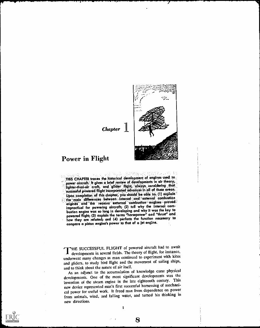
Chapter
Power in Flight
THIS CHAPTER traces the historical development of engines used to,power aircraft.', It gives a brief review of developments in, air theory,lighter-tlicin-air craft, and 'glider- flight, 'always; 'considering that
"successful pnwered flight incorporated advaniet in all of these areOl.Upon ;completion ,of this chapter,. you -shOUld 'be able. to: (1) explain`'
the main differences between ::internal and 'external coMbUstiOnthe 'reasons external prOvid
impractical for powering aircraft; (2) tell why the internal com-bustion engine was so long in developing, and why it was the key topowered flight; (3) eicplain the terms "horsepower" and "thrust" andhow they are related; and (4) perform the function necessary tocompare a piston engine's power to that of a jet engine.
THE SUCCESSFUL FLIGHT of powered aircraft had to awaitdevelopments in several fields. The theory of flight, for instance,
underwent many changes as man continued to experiment with kites
and gliders, to study bird flight and the movement of sailing ships,
and to think about the nature of air itself.
As an adjunct to the accumulation of knowledge came physicaldevelopments. One of the most significant developments was the
invention of the steam engine in the late eighteenth century. This
new device represented man's first successful harnessing of mechani-
cal power for useful work. It freed man from dependence on powerfrom animals, wind, and falling water, and turned his thinking in
new directions.
1
8

PROPULSION SYSTEMS FOR AIRCRAFT
The steam engine was a revolutionary invention, and is still inuse today. As important as the steam engine was, it had a numberof basic characteristics which made it unsuitable for aircraft power.For one thing, the steam engine was too bulky. For another, it wasnot responsive enough to the pilot's control. It was too heavy. More-over, it required external combustion.
External combustion meant that the fire that heated the water andturned it into steam was located outside the engine itself. Thisfeature was more than just an inconvenience for someone who in-tended to fly through the air under power of a steam engine. (Somesteam engines were used in the early days of ballooning, but theywere soon abandoned.)
Improvements in the steam engine led eventually to the develop-ment of the internal combustion engine, which was a very significantdevelopment in the evolution of mechanical power. One of the mostimportant characteristics of the new engine was provision for theburning process to take place inside the engine. The internal com-bustion engine eventually was to provide the power for man's firstsuccessful controlled, powered flight of a heavier-than-air craft.
The development of the internal combustion engine spurred thedevelopment of new metals that were strong enough and light enoughto withstand the stresses of heat and pressure in the engine, whileproviding sufficient power to fly an airplane. Along with the develop-ment of this new kind of engine came new thought on how powercan best be produced and used.
As you have seen in previous study in the Aerospace Educationcourse, the road to successful flight was paved with many ideasfrom many men over a period of many years.
The Wright brothers collected the recorded progress in all of thefields of aviation thought, then added knowledge of their own tothe pool of information. The collective knowledge produced bycenturies of work by a number of people all over the world wasresponsible for the first controlled, powered, heavier-than-air flighton 17 December 1903. That historic flight lasted 12 seconds. TheWright brothers' "Flyer," with Orville at the controls, attained aforward speed of seven miles an hour, and covered a distance ofabout 120 feet.
Those figures do not sound like much today. In fact, they werefar surpassed by the Wrights themselves before that day was over.And after that day, aircraft improvement literally flew forward atan astonishing rate.
2
9

POWER IN FLIGHT
But Orville Wright's flight represented the first successful applica-tion of the distilled knowledge of centuries of thinking, countlessgroping experiments, and an unknown number of unsuccessful at-tempts by men who would have been well satisfied to fly for 12seconds at 7 miles an hour.
Let us briefly review that history.
AIR THEORY
For centuries before the Wrights, man had used the wind forpower. Wind in the sails of ships moved those ships farther andfaster than humans could row. But no one knew how to use thesame wind force for flight. Ancient thinkers on the matter of flyingthought that air was a sustaining forcethat is, that air supportedthe birds, and held them up in the air. They differed on how thebirds moved through the air. Some thinkers believed the birds swamthrough the air like a man swims through the water. Others believedthe bird's forward motion was caused by the air closing aroundthe bird's body, "squeezing" the body forward.
Leonardo da Vinci, 1452 to 1519, subscribed to the "swimming"theory, but he recognized that air hinders flight instead of helpingit. Da Vinci was among the first to realize that air could be com-pressed, and that this compressibility acts to block flight. He madelong studies of birds, and as a result, became a proponent of "stream-lining" to cut down wind resistance as much as possible. Amongda Vinci's drawings arc plans for a parachute; for a kind of heli-copter, which could pull itself through the air with a propeller-likescrew, much as later boats would push themselves through water;and for an "ornithoptcr," a device with bird-like wings that mancould flap with his muscle power, through a system of pulleys. Thiswing-flapping idea seems to have been most common among earlywould-be aviators. (The word "aviator," as a matter of fact, is&rived from the Latin word, "avis," which means "bird.")
In 1680, a biologist named G. A. Borelli published a work explain-ing, among other things, that man's muscles alone would never beable to power a heavier-than-air craft through the air. Bore lli ex-plained that man had a poor ratio of power to weight, as comparedwith the bird. This biological explanation did not convince every-body, though. Some "birdmen" persisted in their attempts to getoff the ground with bird-like wings. There is no record that any ofthem succeeded.
3
(")-A %Jr

PROPULSION SYSTEMS FOR AIRCRAFT
What they could not know was that the bird's wing was far fromthe simple flapping "arm" they saw. In fact, modern high-speedphotography has revealed that the outer primary feathers of a bird'swings function as propellers do to drive the bird forward. Men ofBorelli's time knew virtually nothing about aerodynamics, however,and saw only simple flapping when they looked at a wing inoperation.
Many of the air-minded thinkers after Borelli's day turned theirminds to flying lighter-than-air craft, or balloons. A major problemwith the balloons was how to control their direction of flight. Morethan a century elapsed between the publication of Borelli's workand the invention of the steam engine. The greater part of anothercentury had gone before the steam engine was used to propel bal-loons.
The first aircraft engine was a steam engine developed in 1851by Henri Giffard of France. The engine weighed about 350 poundsand developed 3 horsepower. In September 1852, a cigar-shapedballoon flew at 6 miles an hour for 17 miles under the power ofGiffard's engine, which drove directional propellers.
Internal Combustion Engines
From the time the steam engine was invented, scientists workedconstantly to improve it. Their experiments led away from externalcombustion and toward the development of the internal combustionengine.
It is impossible to attribute to one man the invention of du.internal combustion engine. Its development was made possible byan accumulation of knowledge in mechanical skills, thermodynamics(the effects of heat), experience, and the availability of materials.
The first record of the internal combustion gasoline engine wasreported in 1820 by an Englishman named W. Cecil. The enginewas put into production in 1823 by another Englishman, SamuelBrown. Cecil's engine operated on a vacuum system. The fuelburned inside the engine. As the heated air cooled, it produced avacuum and the vacuum was used for power.
Later experiments showed that better power could be obtainedby using the expansion force of the burning gases, instead of usingthe vacuum of the cooling gases. As a further refinement, in 1838,William Barnett of England suggested that the gasoline would pro-duce more power if it were compressed before it was ignited.
4

POWER IN FLIGHT
The first really practical internal combustion engine was designedin 1860 by the Frenchman. J.J.E. Lenoir. two years later, anotherFrenchman, Alphonse Beau de Rochas. came out with a theoryfor a four -cycle engine. His engine would have four steps: one forintake of the fuel; one for compression of the fuel; one for ignitionof the fuel (the power step); and one for the spent gases to beexhausted.
A German named Nikolaus Otto applied the de Rochas theoryto real engines in 1876. He began manufacturing them in theUnited States in 1878. Finally. Gottlieb Daimler made a valuablecontribution to the propulsion field when he devised a high-speedinternal combustion engine in 1883.
The internal combustion engine was to be the key to powered,heavier- than -air flight.
POWERED FLIGHT
The first internal combustion engine used on an airship, as bal-loons were called then, used coal gas for fuel. It was devised byPaul Haenlein of Germany in 1872, and had four cylinders. Elevenyears later, Albert and Gaston Tissandier of France used an elec-trically- driven engine providing 1.5 horsepower on an airship.
The first use of a gasoline- burning internal combustion engineon an airship came in 1897. David Schwartz of Germany built theengine and installed it on a controllable balloon, or dirigible, madeof aluminum.
A Brazilian, Alberto Santos-Dumont, and a German count, Ferdi-nand von Zeppelin, both worked on lighter- than -air craft (dirigi-bles) powered by internal combustor_ engines. Santos-Dumontstarted his experiments in 1898. Three years later, his dirigible flewa distance of seven milts in 29 minutes. 31 seconds. The 12- horse-power engine could move the 110-foot-long dirigible at 15 miles anhour. Count Zeppelin built a huge dirigible (420 feet long) in 1900and powered it with two internal combustion benzine engines, de-veloping 16 horsepower each.
The future, however, belonged not to the dirigible, but to theheavy aircraft.
Gliders
While the balloons supplied increasing information on enginedesign, valuable information on aircraft design was being gatheredby glider builders.
5

-71
PROPULSION SYSTEMS FOR AIRCRAFT
Sir George Ca ley of England carried out pioneering experimentswith gliders in the years around 1800. Later, the name of Ger-many's Otto Lilienthal became the foremost name among gliderexperimenters. Lilienthal, beginning in 1871, compiled a vastamount of information on aerodynamic principles through his workwith gliders. Two of Lilienthal's disciples, Percy Pilcher of Englandand Octave Chanute of France and the United States, also madeimportant contributions to airplane design through glider work in thelast decade of the nineteenth century.
The marriage of the internal combustion engine to an air framethat incorporated these aerodynamic principles resulted eventuallyin a heavier-than-air machine.
More Power
Continuing advancement of the internal combustion engine nearlybrought to Samuel Langley, an American, the historic honor ofproducing the first successful heavier-than-air craft. Langley, Di-rector of the Smithsonian Institution in Washington, D.C., produceda series of powered model airplanes. The fifth model flew forabout a minute and a half and covered nearly three-quarters ofa mile. As a result of his experimentation in 1898, Congressawarded him a grant to develop a full-size aircraft.
Langley hired Charles M. Manly of Cornell University to buildan engine for the full-size aircraft. Manly responded with a four-cylinder engine, weighing about 151 pounds and developing 52.4horsepower. This engine was a marvel for that time, and theweight-to-power ratio is good even today.
With Manly at the controls. Langley's "Aerodrome" was launchedin October of 1903 from a houseboat on the Potomac River. Partof the aircraft's structure snagged on the launching gear. Manlyand the "Aerodrome" plunged into the river.
The plane was repaired, and on 8 December 1903, Manly madeanother try. His reward was another dunk into the river and hootsof derision from the Nation. the latter shared with Langley.
Nine days later, Orville Wright lifted off a launching rail atKitty Hawk, North Carolina, in the "Flyer," while brother Wilburstood by.
Success
The Wright brothers' flight was no accident. It was the result oflong, hard work, of study of everything they could find on aeronau-
6

POWER IN FLIGHT
tics, of building gliders and testing them, of constructing a windtunnel to try out their ideas. When they could not find writtenmaterial on information they needed, they experimented and devel-oped their own ideas. When they could not find parts they needed,they built their own. For example, they came up short in theirsearch for propeller information, so they had to experiment anddesign their own. The same was true with the engine. After search-ing for a suitable engine to power the "Flyer," the Wrights decidedthey must build their own. All known engines (Manly's was not"known" at that time) were rejected because they were too heavyor lacked sufficient power. Finally, they powered the "Flyer" witha gasoline-burning internal combustion engine, which was built withthe assistance of Charles Taylor, the Wrights' mechanic. The enginehad four cylinders, weighed 170 pounds, and developed 12 horse-power. It drove two wooden propellers.
The Wrights put in many hard hours of work over several yearson their way to their date with history. And they arrived on time.
Jets
Jet propulsion has a different history. The theory of jet powerhas been around for centuries, but it was not until after Isaac New-ton published his ideas on motion in 1687 that the jet was con-sidered feasible as a propulsion device. More than 200 years elapsedafter Newton, however, before anyone considered using a jet engineon an aircraft.
Actually, despite the fact that the principle of jet propulsion wasknown when the aircraft was first flown, the principle was notapplied to aircraft for almost forty years. The reason for this delayincludes the fact that when aircraft first began to fly, the only knownjet engines were of the external combustion type, which were toobulky and lacked power; and that internal combustion jet enginescould not be developed until man had come up with metals strongenough to withstand the tremendous heats and pressures producedinside such engines.
An American, Sanford Moss, contributed substantially to the jetengine, but more or less incidentally. Moss did research on the gasturbine, which was to play a big role in the jet engine's development.The turbine is a mechanical wheel-like device that spins in reactionto a fluid flow over or through it. Although the concept of a turbine
7

PROPULSION SYSTEMS FOR AIRCRAFT
was not 'new, Moss did much to perfect the idea. He experimentedsuccesssfully with the gas turbine in 1902.
An English Air Force officer named Frank Whittle combined thegas turbine and an air compressor to make a jet engine in 1930.But progress stalled until World War II came along. The Englishsuccessfully flcw a jct aircraft in May of 1941, thanks to Whittle.*
But he was not the first. The world's first jet aircraft flew inGermany in August, 1939. The engine was designed by Pabst vonOhain. A year later, an Italian jet aircraft built by Caproni flew
130 miles from Milan to Rome.Whittic's ideas were imported by the United States and eventually
emerged in the form of the P-80 Shooting Star jet aircraft in 1944.This was America's first operational jet aircraft.
The development of the jet leaped forward after World War II.
Rockets
The history of rocketry is long, and originated in China. Rocketswere first used as toys, but can hardly be considered as such today.
Three mcn are credited with pioneering rocket flight and spaceexploration. They are Robert Goddard, an American, known as the
Father of Rocketry; Herman Oberth, a German; and KonstantinTsiolkovsky, a Russian. All three did their work in this century.
The rocket has bccome the key to future space travel, and itsdevelopment has proceeded apace since Russia first launched anearth satellite in 1957.
POWER TERMS
In the discussion of propulsion systems, two terms will be usedto describe the power output of the engine system. These termsare horsepower, used to evaluate the reciprocating engine; and thrust,used to rate the jet and rocket engines.
Horsepower is more or less an artificial word, invented to rate anengine's power in relation to the more familiar power source of
earlier days. To understand horsepower, however, it is necessaryfirst to understand the term work as used in a physical sense. Work
is described as the exertion of a force over a given distance. It is
measured in foot-pounds.
For more details on Air Commodore Whittle, see the booklet. The Coming of theAerospace Age. AE I. p. 76.
8
15

POWER IN FLIGHT
Work is the product of force, or weight, times the distance thatweight is lifted. Time is not a factor in finding the amount of workdone. The formula for determining work is expressed W = F X D.
When James Watt was looking for a way to evaluate the powerof his steam engine, he decided to rate the engine against a familiar
power source, a horse. Watt hitched a brewery horse to a load andprodded the animal to his best effort in lifting that load. Watt foundthat the best that horse could do was to lift the 150-pound load threeand two-thirds feet in an average second.
Using the formula for determining work, Watt found that thehorse had performed about 550 foot-pounds of work per second.One horsepower, then, became equivalent to 550 ft-lb/sec.
The formula for determining horsepower is hpnumber osfoft-lb/sec
With today's big engines, manufacturers have found it more con-ventient to figure the horsepower by the amount of work done perminute. rather than per second.
This formula is stated, hp = number33o.f ft-lb/min the figure 33,000 is merely 550 (one horsepower in seconds) multiplied by 60
seconds.If an engine is capable of lifting 1,000 pounds of weight a dis-
tance of 25 feet in 10 seconds, the same weight could be lifted 2.5
feet in one second. Multiplying 2.5 feet times 1,000 pounds, wefind that the engine performs 2,500 ft-lb of work per second. The
horsepower rating, then would be: 2;557 4.5 hp.
Thrust
The power of jet and rocket engines is expressed in terms ofthrust, instead of in horsepower.
Jet engines operate on the principles of Newton's second andthird laws of motion (force is proportional to the product of massand acceleration, and for every action there is an equal and opposite
reaction).In the jet, the "force" in Newton's second law is the power that
moves the "mass" of air toward the rear of the engine. The "ac-celeration" is the increase in speed of the air mass from the timejust before it enters the jet engine until the time it exhausts.
The formula for determining thrust is Force (in pounds) =Mass (in slugs) times Acceleration (in feet per second), or F = MA.To find the power rating of the jet engine, we substitute the word
9

PROPULSION SYSTEMS FOR AIRCRAFT
Thrust for the word Force in the equation, since the two mean thesame thing in this case.
Mass in slugs is equal to the weight of the air in pounds dividedby the normal acceleration caused by gravity (32.2 feet per sec-ond). Our equation now reads, T = W3e2i8.2ht X acceleration.
Acceleration of the air mass can be determined by subtractingthe velocity of the air before it enters the engine (V1) from the
velocity of the air as it leaves the engine (V2), and dividing theremainder by the time required to change the velocity. Assumethat the aircraft (and the engine) is standing still. VI would then
be, for our purposes, zero. If the exhaust velocity (V2) is 1,500feet per second, then the rate of velocity increase (acceleration)would be 1,500 feet per second per second. This would usuallybe stated 1,500 ft /sect.
Imagine, then, a jet engine capable of handling 150 pounds ofair per second, and producing an exhaust velocity of 1,500 feet persecond. Assume that the engine is stationary, making V1 zero.The thrust could then be computed as follows:
T=
15 0 X (1,500 0)T = 4.65 x 1,500T = 6,975 pounds
Thrust Horsepower
To get an idea of how thrust of a jet engine compares to horse-
power of a reciprocating engine, we may use a formula for deter-mining the unit called thrust horsepower (thp).
This formula is stated, thrust ' rscpower = tpriht ;airspeed
The figure "375" in the formula is horsepower in mile-poundsper hour, and is simply an expansion of the more familiar 550 ft-lb/sec, or 33,000 ft-lb/min.
Thus, if a jet aircraft requires 10,000 pounds of thrust to travel
at a speed of 800 miles per hour. the thrust horsepower would be10,000373( 800
thp = 21,333

POWER IN FLIGHT
REVIEW QUESTIONSI. Name one basic difference between the steam engine and the engine used
to power the Wright brothers' "Flyer."
2. What was the contribution of balloon fliers to successful heavier-than-airflight? What was the contribution of glider fliers?
3. How did Charles Manly's engine, which he used on the "Aerodrome,"compare with the engine that powered the Wright brothers' "Flyer?"
4. The theory of jet power is very old. Why was jet propulsion not used topower aircraft in the early days of aviation?
5. Name three men who were instrumental in the development of themodern rocket.
6. What term is used to evaluate the performance of the reciprocating engine?The jet engine?
7. What formulas are used to find horsepower or thrust ratings for engines?How do "horsepower" and "thrust" compare?
THINGS TO DOI. The development of internal combustion engines forced the development
of metals and other materials capable of withstanding the stresses of heatand pressure of the new engine. Modern jet and rocket engines developheat and pressures much greater than the first internal combustion engines.Find some good examples of new materials developed as a direct result ofmodern propulsion systems. List some uses for these new materials inareas other than propulsioti systems.
2. Although the first men to achieve powered flight were Americans. theirbiggest acclaim and the most immediate follow-up to their accomplishmentcame from Europe. Similarly, pioneering work in rocketry was done in theUnited States, but Europe made far more early use of it than America.Find out what historical and social factors led to this situation. Speculateon whether any of the same or similar factors are at work today, orwhether the situation has been reversed. Explain your deductions andobservations.
SUGGESTIONS FOR FURTHER READINGBRYAN, LESLIE A., and others. Fundamentals of Aviation and Space Tech-nology. Urbana, Ill.: Institute of Aviation, University of Illinois. 1966.GIBBS-SMITH, CHARLES. The Invention of the Aeroplane, 1799-1909. New
York: Tapp linger, 1966.
History of Flight. n.p.: American Heritage Publishing Co., Inc., 1962. JepcoBriefing Booklet BT-1. An Introduction to Turbine Aircraft. Denver:Jeppesen & Co.. 1958.
VAN DEverrER, C. N. An Introduction to General Aeronautics. Chicago:American Technical Society, 1965.

Chapter
Reciprocating Engines
THIS CHAPTER is concerned with the performance of the recipro-cating engine, the numerically dominant engine in aviation today.It reviews the mechanical functioning of the reciprocating engine,beginning with the power cycle and including the necessity and
means of cooling the engine. When you finish this chapter, youshould be able to: (1) describe the power cycle of the reciprocatingengine, explaining what happens during each step; (2) explainhow diesel engines differ from reciprocating engines and whydiesels are not used in aircraft; (3) explain the differing character-
istics of in-line and radial engines and their relative advantagesand disadvantages; and (4) describe clearly the workings of aircooling and liquid cooling systems in reciprocating aircraft enginesand tell which is preferred and why.
THE AGE of the jet aircraft has had a profound influence onthe
thinking of air - minded Americans. The jet suggests speed andglamor and, indeed, it provides both. But in the field of generalaviationthat is, all aviation except commercial airlines and mili-tary aviationmore than 99 percent of all aircraft arc powered bythe "old-fashioned" propulsion system of piston engine and pro-peller. This engine, where the power is produced by the back-and-forth motion of the pistons, is called a reciprocating engine.
THE RECIPROCATING ENGINE
The reciprocating engine is dominant in general aviation not onlybecause it has been around longer than the jet, but because it is
13

PROPULSION SYSTEMS FOR AIRCRAFT
BASIC PARTS OF ANENGINEEVERY INTERNAL COMBUSTIONENGINE MUST HAVE CERTAINBASIC PARTS IN ORDER TO CHANGEHEAT INTO MECHANICAL ENERGY
THE CYLINDER FORMS A PART OFTHE CHAMBER IN WHICH THE FUEL
IS COMPRESSED AND BURNED
AN INTAKE VALVE IS NEEDED TO LETTHE FUEL INTO THE CLOSED CYLINDER
AN EXHAUST VALVE IS NEEDED TOLET THE EXHAUST GASES OUT
THE PISTON. MOVING WITHIN THECYLINDER. FORMS ONE OF THE WALLSOF THE COMBUSTION CHAMBER. THEPISTON HAS RINGS WHICH SEAL THEPISTON IN THE CYUNDER. PREVENTINGANY LOSS OF POWER AROUND THESIDES OF THE PISTON.
THE CONNECTING ROD FORMS ALINK BETWEEN THE PISTON AND
THE CRANKSHAFT
THE CRANKSHAFT AND CONNECTING ROD CHANGE THE STRAIGHT LINE MOTIONOF THE PISTON TO A ROTARY. TURNING MOTION THE CRANKSHAFT IN AN AIRPLANEENGINE ALSO ABSORBS THE POWER OR WORK FROM ALL THE CYLINDERS AND TRANSFERSIT TO THE PROPELLER.
Figure 1. Basic Parts of an Engine.

ti
RECIPROCATING ENGINES
Figure 2. Four-stroke Engine Cycle.
well suited for the job it is called on to perform; that is, to deliverefficient, reliable, economical service at speeds below the speed ofsound and at altitudes below 40,000 feet. Because of the dominanceof this cnginc, it is important that we know something about it. Inmany ways, you will find that the aircraft's reciprocating cnginc issimilar to the cnginc in most automobiles, with the main differencesbeing that the aircraft engines are more powerful, more rugged,and lighter for the horsepower they develop. We will begin ourstudy of the reciprocating cnginc by examining the mecharti,:al sys-tem, where the power is developed.
The Mechanical System
Reciprocating engines used in aircraft have certain mechanicalparts vital to their operation. These parts may be arranged in anyof several different ways. but the design of the parts themselvesremains more or less standard. These vital parts include the cylin-der; the piston; the connecting rod; the crankshaft; and the valves.(Fig. 1).
15

PROPULSION SYSTEMS FOR AIRCRAFT
Figure 3. Piston-Crankshaft Connections.
Reciprocating engines used to power aircraft operate on what iscalled the four-stroke cycle. This means that the piston makesfour strokesmovements from top center to bottom center of thecylinder, or from bottom center to top centerto accomplish thefive stages in each complete action cycle.
The five steps in each cycle are: (1) intake, (2) compression,(3) ignitior (4) power, and (5) exhaust. The third step, ignition,occurs just before the end of the compression step and is thus con-sidered as a part of the piston's second stroke. (Fig. 2)
The cylinder is the combustion chamber in which the engire'spower is developed. The piston is designed to fit into the hollowcylinder snugly, but not so snugly as to prevent free up-and-downaction by the piston. A connecting rod links the piston to the crank-shaft, outside the cylinder. The crankshaft is so designed as to con-vert the piston's up-and-down motion into the circular motion re-quired to turn the propeller, which is attached to the end of thecrankshaft. The crankshaft is not straight, but has throws or bendsin it. The connecting rods are attached to these throws. (Fig. 3)
At the top of the cylinder. in the cylinder head, are located twovalves, an intake valve and an exhaust valve. The opening andclosing of these valves allows the fuel to enter the cylinder and theexhaust gases to leave it. This opening and closing is regulated byrings or lobes on a cam shaft, which is located adjacent to the crank-shaft. The cam shaft is connected to the crankshaft through aseries of gears.
16
3

RECIPROCATING ENGINES
This camshaft-crankshaft connection provides synchronization ofboth shafts, the valves and the piston. The rings on the cam shaftthe cam ringsare made off-round, or eccentric. By pressing andreleasing the tops of the valves in a timed sequence, the cam ringsact to insure that each valve opens and closes at the proper time inthe cycle.
With all of this in mind, then, let us look at the action that pro-duccs the power that drives the propeller.
Intake Stroke.--The piston begins the cycle from the location attop center of the cylinder. As the piston moves downward, towardthe bottom of the cylinder and toward the crankshaft, the intakevalve at the top of the cylinder and above the piston opens. Thisis due to the reduced pressure inside the cylinder, caused by themovement of the piston. The increased volume inside the cylinderand the lowered pressure force the pre-mixed fuel and air mixtureto enter the cylinder through the intake valve.
Compression Stroke.The piston reverses its direction startingback toward the top of the cylinder. Both the intake and the ex-haust valves are closed, due to the cam ring action. The piston de-creases the volume inside the cylinder, compressing the fuel mixtureinto a small space. Just prior to the end of this stroke, about 20 or30 degrees from the top of the cylinder, a spark from the sparkplug ignites the fuel. The momentum of the piston's upward move-ment carries the piston to the top of the stroke.
Power Stroke.The fuel mixture, ignited by the spark, is burn-ing now as the piston again reverses its direction. The burning fuelforms a large volume of gas, which creates tremendous pressure.This pressure drives the piston down forcefully. This power strokeis the whole reason for an engine.
Exhaust Sf-oke.Slightly before the piston reaches its down-ward limit and reverses direction once more, the exhaust valve atthe top of the cylinder opens. As the piston moves upward on itsfinal stroke of the cycle, it forces the spent gases out of the cylinder.As the piston reaches the top of its final stroke, the exhaust valvecloses and the cycle begins again.
This four-stroke cycle occurs at the same time in the other cylin-ders of the engine, but no two cylinders are at tl.a same stage of thecycle at the same time. The cylinders are tined to fire in sequenceto insure a smooth flow of power to the crankshaft and from it to thepropeller.
17

PROPULSION SYSTEMS FOR AIRCRAFT
Each cylinder goes through a complete cycle approximately 1,000times every minute the engine is in operation. An engine with 18cylinders, then. furnishes the propeller with about 300 power strokesper second.
Diesel Engines
The aircraft engines we are discussing use a mixture of gasolineand air for fuel. You may be familiar with another type of engine,the diesel. This is the powerful engine used on railroad trains andmost heavy trucks today. Diesel engines are not used on modernaircraft, primarily because they are too heavy.
The diesel engine. named after Rudolf Dicsel, its inventor, workson much the same same principle as does the four - stroke cycle gaso-linc engine we have been discussing. But its fuel is an oil that is notnearly as combustible as is gasoline. In fact, there is no explosionas such in the operation of a diesel engine. The diesel has no needfor spark plugs and carburetors.
A basic difference in the operation of gasoline and diesel enginesis that on the compression stroke of the diesel. no fuel is yet in thecylinder. The piston compresses air only.
Compressing a gas, such as air, makes the gas hot. In the gasolineengine, the gasoline-air mixture may be compressed to about one -ninth itz original volume. If compressed more than that, it willexplode. The explosion would. of course, prevent the piston fromreaching the top of the cylinder and the engine woad not work.
In the diesel engine. however. the air in the cylinder is com-pressed to about one-fifteenth its original volume. The temperatureof the air in the cylinder rises above the burning point of the fuel oil.At the top of the compression stroke. the fuel oil is injected underpressure into the cylinder and burns immediately. The expandinggases force the piston down and supply the power, just as in thegasoline engine.
The diesel would seem to offer advantages for use in aircraft.Since the fuel oil is not as combustible, it would be less likely toexplode in case of a crash. Moreover. it is cheaper than gasoline.But although the diesel provides more power per cylinder thandoes the gasoline engine, it does not provide as much power perpound of weight. The reason for this is that the diesel engine mustbe built very stronglyand very heavilyto withstand the tremen-dous pressures of the compression inside the cylinders. For this
18

RECIPROCATING ENGINES
reason, the diesel is considered too heavy for aircraft use. Thediesel engine also is more sluggish than the gasoline engine anddoes not react as quickly to the throttle. It is better suited to usewhere weight is not too important and where economy is needed.
Types of Reciprocating Engines
A constant concern of engine manufacturers is the problem ofhow to get more horsepower from their engines. With the reciprocat-ing engine, there are two basic ways to accomplish this end. Oneway is to increase the number of cylinders in the engine.
The practical limitations on increasing the size of the individualcylinders are so restrictive that manufacturers have concentrated onthe other method, the development of multi-cylinder engines. Not
Figure 4. Types of Engine Designs.
19tt-JU

PROPULSION SYSTEMS FOR AIRCRAFT
the least advantage in using this method is the added smoothnessof power supply, brought about because of the added number ofpower strokes per revolution of the crankshaft.
Manufacturers have come up with several different engine de-signs and configurations to accommodate the addition of cylinders.The most common designs in use today are the in-line and the radialengines. (Fig. 4)
In-line engines.The in-line engine is one in which the cylindersare located in a row, one behind the other, along the crankcase (thecasing through which the crankshaft runs). The cylinders, then,are in line, hence the name of the engine.
To accommodate the additional cylinders, the crankshaft mustbe lengthened and its number of bends (throws) must be increased.
If th%. cylinders are located above the crankcase, the engine typeis called upright. If the cylinders are below the crankcase, the enginetype is called inverted.
One type of in-line engine has two rows, or banks, of cylinders,one row on each side of the crankcase. The rows of cylinders aredirectly opposite each other, and the engine type is called hori-zontal opposed.
The in-line engines can come in a variety of designs, includingthe "V" and the "X." (See Fig. 4.) But these different arrange-ments still are put together in the same fundamental "in line" man-ner.
In the manufacture of the in-line engines, the cylinder headsmay be cut separately or the whole bank of cylinders may be castin one block, then machined to specification. Usually, the way inwhich the engine is to be cooled determines the way in which thecylinder heads are made. If the engine is to be cooled by air, theindividual cylinder heads usually are cast separately. If liquid cool-ing is to be used, the heads usually are cast in one long block.
In-line engines are used in almost all of the smaller aircraft. Thetype of engine used for the small craft is usually the horizontalopposed, due to its streamlining advantages.
The in-line engines used to power these light aircraft are usuallyair cooled, which eliminates the need for the extra weight and ma-chinery of the liquid cooling system. The larger, more powerfulin-line engines employ the liquid cooling system, however, because itis very difficult to cool the rear cylinders with air.
Due to these cooling difficulties, the air-cooled in-line engine ofthe opposed type rarely produces more than 250-300 horsepower.
. 20

RECIPROCATING ENGINES
This limitation is the result of the limitation on the number of cylin-ders which can be cooled by the air system.
The in-line engine is usually a very compact package with asmall diameter. The liquid cooled version offers very good, evencooling for the individual cylinders. This normally increases the lifeof the engine and reduces engine failure.
Where more horsepower is essentialin the larger aircraft, forinstancethe radial engine is used.
Radial engines.The radial engine features a crankshaft withonly one throw. The cylinders are arranged around the crankshaftin a circle in such a manner that all the cylinders and connectingrods contribute their power through the single throw. One of thecylinders is designated as the master cylinder. The connecting rodfrom the piston in this cylinder is called the master rod, and attachesto the throw of the crankshaft.
Other connecting rods, called articulating or link rods, connect theother pistons to the large end of the master rod. The master rod,however, is the only rod that is connected directly to the crankshaftitself.
The radial engine always has an odd number of cylinders ineach bank. This feature is required by the firing order of the four-stroke cycle. The maximum number of cylinders in each bank isusually nine. Where more power is needed from an engine, addi-tional banks of cylinders may be added behind the first bank.
Where more banks are added, the crankshaft must be lengthenedto accommodate the master cylinders in each additional bank. Theseextra banks operate in the same manner as does the original. Ineffect, a radial engine with two banks of cylinders is two enginesworking together, one behind the other. The design of the radial en-gine features fewer working parts and less weight than that of anin-line engine developing comparable power.
The radial engine is air cooled. Where more than one bank ofcylinders is built into the engine, the air passes through the firstbank and encounters a series of baffles. These baffles direct theair around and through the other banks of cylinders to cool therear of the engine.
It is not uncommon to see radial engines with four banks ofcylinders. Such engines can develop more than 3,500 horsepowereach. When more power is needed, the radial engines may be usedin sets of two, or even in groups of up to eight engines.
21 QiJv

PROPULSION SYSTEMS FOR AIRCRAFT
Performance of Reciprocating Engines
Manufacturers perfer the air-cooled radial engine for the heavieraircraft and the air-cooled inline engine for planes requiring lessthan 300 horsepower per engine.The propulsion system composed of a reciprocating engine andpropeller is efficient at speeds up to about 400 miles per hour andat altitudes below 40,000 feet. Such a system can create a large
amount of thrust at low speeds and so can get an aircraft off theground after a relatively short takeoff run. This propulsion systemcan carry more weight farther, and on less fuel, than any other kindof propulsion system in its speed range. It is dependable, and hasbecome, through years of development, rugged and simple to main-tain.
The propeller-reciprocating engine system of propulsion can pro-vide very fast acceleration. The engine responds immediately andcan change from a low to a high power output in a very short periodof time. It is versatile and efficient. That is why, in this age ofpowerful and very fast jet planes and rockets, the propeller-drivenaircraft, powered by the reciprocating engine, is still seeing ex-tensive use.
HEAT AND COOLING
Reduced to basic essentials, the purpose of an engine is to pro-duce energy, and this energy is in the form of heat. Without heat,the engine would not drive the propeller. But that same elementheatis the primary source of wear and tear on the engine.When the fuel and air mixture burns in the cylinder of an engine,
about one-third of the resulting heat drives the piston downward.This is the only useful energy produced by the engine. Some two-thirds of the total heat produced is wasted. Of the lost portion ofthe heat, about one-half is pushed out into the atmosphere throughthe exhaust valve. The remaining heatone-third of the total pro-duced by the enginedoes not escape and does not perform anyproductive work. Instead, it is trapped in the walls of the cylinder,in the piston, and in the lubricating oil of the engine. Unless thisheat is disposed of, it can wreck the engine.
There are two ways to carry off the excess heat. One way isthrough the use of the air through which the engine is traveling;the other way is through the use of a liquid cooling agent carried
22

RECIPROCATING ENGINES
along for the sole purpose of cooling the engine. Whichever way isused, special features are built into the engine to assist in the cooling.
One of the most noticeable of these features is the system of finsor flanges machined onto the head and barrel of the cylinders.These fins expose a broader surface to the cooling effects of theair or liquid coolant.
In the early days of aviation, the engines were exposed only tothe direct air current through which the aircraft were flying. Theair flowed over the engine, carrying off some of the excess heat, butthat system proved effective only at a fairly low rate of revolutionsper minute by the crankshaft.
The air cooling system developed along with the development ofmore powerful engines, which turned the crankshaft at a fasterrate. The fins on the cylinders are an example. Another developmentwas the enclosure of the engine in a cowling, or cover, with asystem of cowling flaps and air baffles built in. This system slowsdown the air to the speed at which it does the best job of cooling.The cowling flaps control the volume of cooling air enteringthe cowling. The flaps can be operated or closed by the pilot.The air cooling system is effective not only at cruising speedsand normal altitudes, but on the ground and at high altitudes.(Fig. 5)
On the ground, the only air available to cool the engine is thatproduced by the propeller's action. In this situation the engine, asyou can imagine, would tend to run hot. In contrast, the air at highaltitudes is very cold, and, in addition, a greater volume of air is
Figure 5. Mr Cooling, with Cowling Flaps Open.
23
30
PROPULSION SYSTEMS FOR AIRCRAFT
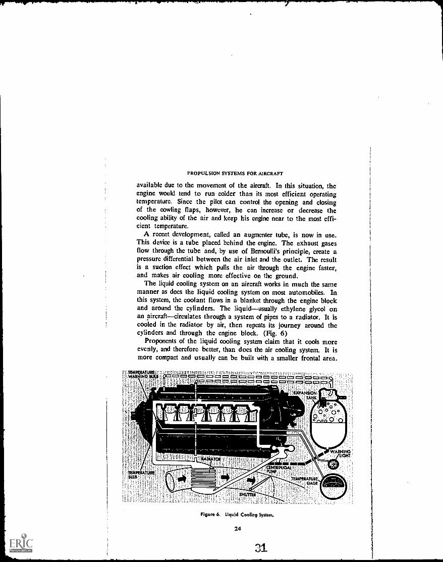
available due to the movement of the aircraft. In this situation, theengine would tend to run colder than its most efficient operatingtemperature. Since the pilot can control the opening and closingof the cowling flaps, however, he can increase or decrease thecooling ability of the air and keep his engine near to the most effi-cient temperature.
A recent development, called an augmenter tube, is now in use.This device is a tube placed behind the engine. The exhaust gasesflow through the tube and, by use of Bernoulli's principle, create apressure differential between the air inlet and the outlet. The resultis a suction effect which pulls the air through the engine faster,and makes air cooling more effective on the ground.
The liquid cooling system on an aircraft works in much the samemanner as does the liquid cooling system on most automobiles. Inthis system, the coolant flows in a blanket through the engine blockand around the cylinders. The liquidusually ethylene glycol onan aircraftcirculates through a system of pipes to a radiator. It iscooled in the radiator by air, then repeats its journey around thecylinders and through the engine block. (Fig. 6)
Proponents of the liquid cooling system claim that it cools moreevenly, and therefore better, than does the air cooling system. It ismore compact and usually can be built with a smaller frontal area.
yiTERLAR
to= = =lc= = c=1=3 c= C=3 c=1
TANK
011111P00 ° 0°
o on
CENTR IFUGAL',
PUMP
TEMPERATUREGAGE
TEMPERATURE,
'SHUTTER
Figure 6. Liquid Cooling System.
24
til*I/h<RNINGLIGHT

RECIPROCATING ENGINES
Hardened Tip.
Large Stem
Sodium Chamber
HOLLOW.HEAO TULIP TYPEMUSHROOM TYPE (EXHAUST) , : (USUALLY. INTAKE)
Figure 7. Cutaway Drawing of Valves.
But the liquid system is more costly to build and more complicatedto maintain than is the air cooling system. In military aircraft, it ismore vulnerable to enemy fire. For these reasons, the liquid coolingsystem has been nearly abandoned by United States engine manu-facturers since World War II.
CONSTRUCTION MATERIALS
Since the heat generated in an engine is so intense, manufacturersmust be careful in choosing materials that can withstand the heatand keep their strength and shape.
The cylinder is the seat of the engine's action, and is thereforesubject to very high temperatures and pressures. The cylinder barreland head must be very strong. The cylinder barrel is made of ahigh-grade steel alloy. It is machined to very close specifications.The inside of the cylinder barrel is highly polished and is harderthan glass. The cylinder head is made of cast or forged aluminumalloy and is "shrunk" onto the cylinder barrel.
The shrinking process consists of heating the cylinder-head, thenscrewing it onto the cylinder barrel. The inside of the cylinder headis slightly smaller in diameter than is the outside of the eylinderbarrel. Both are threaded. Heating expands the metal of the cylin-der head so that it may be screwed onto the barrel. When the metalcools, the head is locked tightly into place.
The valves also are subjected to intense heat and high pressure.They are made of tungsten steel or chromium steel, which providestrength at high temperatures. The faces of the valvesthat por-tion which is actually exposed to the heat inside the cylinderare
25

PROPULSION SYSTEMS FOR AIRCRAFT
coated with a thin layer of stellite, which resists pitting and burning.The intake valve usually is solid, but the exhaust valve is hollow.The hollow is filled with salt solution of metallic sodium, which con-ducts the heat away from the valve head. (Fig. 7)The pistons are made of forged or cast aluminum. Aluminum isused for the pistons because it is strong, it has compatible charac-teristics with the steel of the cylinder barrel, and because aluminumpistons are light enough to stop at the end of each stroke withoutcausing undue stress on the other mechanical parts. Aluminum isalso a good heat conductor and is therefore easy to cool.The connecting rods arc made of steel and the piston pins, whichconnect the connecting rods to the pistons, are made of tough nickelsteel.
The heat on the crankshaft is primarily that produced by friction,and not by the action in the cylinder. But the crankshaft is sub-jected to the most violent twisting movement and must be made ofvery strong material to withstand the forces exerted on it. There-fore, the crankshaft is made of chromium steel. The crankcase isusually made of aluminum in smaller engines and of steel in thelarger ones.
REVIEW QUESTIONS1. What are the principal parts of the reciprocating engine?2. Name the five steps in the operation of the four-stroke engine.3. What is the function of the cylinder in the reciprocating engine? What isthe purpose of the crankshaft?4. Describe the action of a four-stroke engine.S. Why are Diesel engines not used in aircraft?6. What is an "inline" engine? What is a "radial" engine? Name someadvantages of each type.7. Name some advantages of the propulsion system composed of a recipro-cating engine and propeller.8. What percentage of the heat developed in the chamber is used to drive
the piston downward? What happens to the remaining heat?9. What is a cowling? What is its function?
10. Name some materials used in the construction of the engine parts.
26
33

t
RECIPROCATING ENGINES
THINGS TO DO
1. Diesel engines were tried experimentally on aircraft in the early 1940's,but were found unsuitable. Find out if advances in the developmentof strong, light-weight metals and improvements in diesel design haverevived the prospects of diesel aircraft engines. Report tq the class andexplain your findings, whether positive or negative.
2. Recently, there has been developed an engine known as the rotatingcombustion engine. Plans for this engine include application to aircraft,automobiles, boats, and industrial uses. Find out and report on theoperation of this engine and its current status. What are its prospectsfor wide acceptance?
SUGGESTIONS FOR FURTHER READING
CHAPEL, CHARLES E., ed. Aircraft Power Plants. New York: McGraw-HillBook Co., 1948.
GUNSTON, W. T., ed. Flight Handbook: The Theory and Practice of PoweredFlight. Los Angeles: Aero Publishers, 1962.
MCKINLEY, JAMES L., and RALPH D. BERT. Powerplants for Aerospace Ve-hicles. New York: McGraw-Hill Book Co., 1965.
VAN DEVENTER, C. N. An Introduction to General Aeronautics. Chicago:American Technical Society, 1965.
VAN SICKLE, NEIL D., ed. Modern Airmanship. Princeton, N.J.: D. VanNostrand Co., Inc., 1966.
27 Z,4

Chapter 3
Other Engine Systems
WHERE CHAPTER 2 considered the mechanical system of the re-ciprocating engine, this chapter considers other engine systems,namely the fuel system, with emphasis on carburetion; the ignitionsystem; the lubrication system; and the propeller system, with sometheoretical discussion of propellers. When you finish this chapter,you should be able to: (1) discuss the desirable qualities of gasolineand tell why it is the ideal fuel for aviation engines; (2) describewhat happens in the carburetor, why this function is necessary, andhow it occurs; (3) explain what happens in the operation of theignition system; (4) explain the function of the lubricating system;and (5) describe the workings and limitations of the propeller.
THE CYLINDERS, pistons, valves, crankshaft, and related partsthat we have discussed make up only one section of the engine,
the section called the mechanical system. If fact, there are a numberof engine sections which work together to provide power to movethe aircraft. These different sections all must work properly withinthemselves and in cooperation with all the other sections if the totalengine is to function well.
It is only for convenience in study that we divide the engine intoits different systems. With that fact in mind, in this chapter we willexamine engine sections other than the mechanical system and thecooling system. These other sections include the fuel system (includ-ing the carburetor), lubrication system, ignition system, Lndpropeller system; their related parts; and their functions as parts ofthe whole engine.
29

PROPULSION SYSTEMS FOR AIRCRAFT
STRAIGHTRUN GASOLINE
KEROSENE
DIESEL FUEL
FUEL OIL &LUBRICATINGOIL. STOCKS
CRUDEPETROLEUM
1
HEATER
yf
figure 8. Products Derived from Petroleum.
FUELS
The fuels in use in today's aircraft are the result of extensiveexperimentation in search of the best fuel for the most reasonableprice. The commonest forms of aircraft fuels are the hydrocarbonsderived from petroleum.
"Hydrocarbon" is merely the descriptive name supplied by chem-ists to materials which contain only the chemical elements hydrogenand carbon in their structure. The principle hydrocarbon fuels inuse in aircraft power today are gasoline and refined kerosene. Thesefuels, as well as diesel fuel, fuel oil, lubricating oils, and other prod-uts, all are distilled from petroleum. (Fig. 8)
The petroleum-derived gasoline and kerosene used as aviationfuels offer several advantages:
1. They are volatile. They evaporate quickly and can be mixedeasily with air to form a combustible mixture.
2. They have relatively low "flash points." That is, when theyare mixed with air they ignite at relatively low temperatures. If theflash point of a fuel is too high, the result is difficulty in starting theengine.
3. Petroleum-based fuels have low freezing points. This is im-portant when the aircraft is operating in the low temperatures ofhigh-altitude flight. It also comes in handy when the fuel must bestored in the cold temperatures of the northern regions.
4. They have a relatively high heat content. This means there ismuch potential energy within the fuel which may be converted to
30

OTHER ENGINE SYSTEMS
kinetic energy as the fuel burns. Potential energy is that energywhich is at rest. Kinetic energy is energy actually at work.
5. The fuels are relatively stable. They can be easily handledunder fairly simple safety precautions, and they will not deterioratewhen stored over long periods of time.
6. They are readily available at relatively reasonable cost.The petroleum from which gasoline and kerosene are derived, is
found deposited in most regions of the world. Petroleum also isthe source of automobile gasoline and other common fuels. But thefuels used in aircraft require stricter control in production than dothe "ordinary" fuels used in automobiles. These controls are im-portant because a failure in the engine of an aircraft can be muchmore serious than a failure in a car engine. A pilot cannot just pullover to the side of the road and call a mechanic.
Volatility
Aircraft fuel must be highly volatile so that the engine will starteasily. But it must not be too volatile, or trouble can result.
One result of too much volatility is the vapor lock. In this con-dition, the gasoline "boils" in the fuel line before it reaches thecarburetor. This "boiling" causes air bubbles to form in the fuelline. The air bubbles block or partially block the flow of the liquidfuel, so that an insufficient amount of fuel gets through to operatethe engine.
Too much volatility also can lead to carburetor icing. We knowfrom science that vaporization of a liquid requires heat. The heatused for vaporization of aircraft gasoline is taken from the air andfrom the metal surrounding the fuel. Gasoline of high volatility ex-tracts this heat very quickly. When too much heat is taken fromthe metal parts for vaporization, the remaining cold will cause iceto form in the valves of the carburetor, and stop the proper opera-tion of the carburetor. The carburetor, which will be explainedmore fully later in this book, is the device which mixes the fueland air to the proper proportions for engine operation. If thecarburetor does not operate as it should, the engine will fail. Variousproduction tests are performed on aircraft fuels to insure that theyare volatile enough for efficient engine operation but not too volatilefor safe operation.
The octane rating of aircraft fuels also is important. In fact,manufacturers specify the octane rating of the fuels which will
31

PROPULSION SYSTEMS FOR AIRCRAFT
function best in each engine. The octane rating is simply a num-ber describing the antiknock performance of the particular gasoline.A fuel of low antiknock value, used in a high-performance engine,may cause any of several dangerous consequences. Three types of"knock" are fuel knock, pre-ignition knock, and detonation.
Fuel knock is the result of uncontrolled burning of the fuel in theengine's cylinder. TI,^ fuel charge may burn evenly part of the wayacross the cylinder, then unevenly across the remainder. It maydamage any of several vital engine parts.
Pre-ignition knock results when the compressed charge in thecylinder ignites before the electrical charge from the spark plugcan jump the gap between the spark plug's electrodes, or points.This upsets the timing of the engine and also can cause damage.
Detonation is a severe fuel knock which creates pressures tooextreme for the valves, the piston, and in some cases even thecylinder head to endure for any period of time. Detonation maybe described as an uncontrolled explosion of the fuel in the cylinder,
Figure 9. How Detonation Compares with Normal Burning.
OTHER ENGINE SYSTEMS
due to spontaneous combustion. It can completely wreck the cylin-der and its parts. (Fig. 9)
Fuel knock, pre-ignition knock and detonation may be causedby malfunctions of the mechanical pall of the engine, but they mayalso result from the use of low-grade fuel. That is why the gasolineto be used must have the proper Octane Rating.
Octane Rating
The octane rating gets its name from one of the hydrocarbonscontained in the fuel, called iso- octane. Iso-octane has high anti-knock properties, while the other common hydrocarbon in fuel,heptane, has low anti-knock properties.
The octane rating applied to a particular fuel originally indicatedthe percentage of iso-octane contained in the fuel. Because of itshigh anti-knock properties, pure iso- octane was arbitrarily giventhe number 100 to describe its anti-knock performance. For ex-ample, a gasoline rated 65 octane would be a mixture containing65 percent iso- octane. But you may have seen fuels with octaneratings above 100. This is possible because chemists discoveredthat certain other elements blended into fuel with a high percentageof iso-octane actually could increase the anti-knock performance ofthe fuel beyond the level of pure iso-octane. The most commonly-used of these blending agents is tetra-ethyl lead.
Thus, a fuel with an octane rating of 130 would contain a highpercentage of iso- octane, plus a quantity of another blending agent.The octane rating no longer describes merely the percentage ofiso-octane in the fuel, but is a rating of the fuel's anti-knock per-formance.
Fuels with high octane ratings are used primarily in large en-gines specifically designed for them. The high anti-knock propertiesof this high-octane fuel allows higher compression of the fuel in thecylinder before it is ignited. The higher compression in turn yieldsa stronger "explosion" of the fuel charge when it is ignited, andhigher power from each cylinder.
Now that we know the nature of the aircraft's fuel, let us see howthat fuel finds its way into the engine and through the fuel system.
THE FUEL SYSTEM
The fuel system is a network of tanks, lines, gauges, pumps,strainers and screens. Its purpose is to deliver to the carburetor a
33
4 0

PROPULSION SYSTEMS FOR AIRCRAFT
steady flow of clean fuel under constant pressure. This delivery mustcontinue at all operational altitudes of the airplane, and in all ofthe plane's positions, or attitudes, including diving, climbing oreven flying upside down as well as level flight. To be sure these re-quirements are met, gravity-feed or mechanical pumping is em-ployed.
FUEL FEEDING
The gravity-feed fuel system, the simplest type used, is commonin small planes whose engines have relatively low horsepower. Inthis system, the fuel tank is located above the level of the carburetorinlet. The pressure behind the fuel flowing through the lines isbuilt up by the weight of the fuel behind it, flowing from the higherlevel of the tank to the lower level of the carburetor inlet.
The gravity-feed fuel system is light-weight, easy to maintain andsimple in design and operation. But it is not suited for high-powered aircraft.
The force-feed fuel system features an engine-driven pump whichdraws the fuel from the tank and forces it into the carburetor. Theuse of the pump means that the tanks do not have to be locatedabove the carburetor inlet, but may be placed wherever there isample and convenient space. A hand operated pump, called a wobblepump, is included for use in case of emergencies, if the engine-driven pump fails. The pumps may be arranged side by side, orparallel, or in series. The series arrangement is preferred for usein fast-climbing aircraft. (Fig. 10)
- 'CARBURETOR
FUEL COCK,
Figure 10. Fuel System with Pumps in Series.
34

OTHER ENGINE SYSTEMS
The force, or pressure, system is used in larger planes with morethan one engine. This type of system makes possible the high fuelpressure required by many modern aircraft carburetors. Since theconstant supply of fuel is assured, the plane has more maneuver-ability.
A series of strainers ,and screens is included in the fuel system toassure that water, dirt and other foreign matter does not get throughthe system. If these elements were able to go through the fuel sys-tem, dire consequences could result.
Water is heavier than gasoline and settles to the bottom of thetank. When the aircraft is in flight, the water may get into thefuel lines, freeze at high altitudes and block off the flow of gasolineto the engine. A tiny particle of dirt may block off the meteringjet in the carburetor and wholly or partially block the gasoline's flowto the engine. In either case, the engine fails either partly or com-pletely. To be sure that these impurities are not present in the fuelsystem, the ground crew usually checks the strainers, screens andtraps for accumulated water and dirt immediately after refueling theaircraft. After passing through these strainers and filters, the cleangasoline is fed through a most important part of the fuel system,the carburetor.
The Carburetor
Gasoline in its liquid form burns too slowly for good engine per-formance. But mixed with air, gasoline is the most satisfactory air-craft fuel yet found for use in reciprocating engines. The carburetoris a device built into the engine to atomize the gasoline, measureit to proper quantities, and mix it with air. The proper air-gasolinemixture is one that will burn slowly, evenly, and completely.
The word "carburetor" comes from the same root word as doescarbon. The dictionary describes "carburetor" as a device whicheffects the chemical mixing of an element with carbon. In this case,the carbon is found in the hydrocarbons of the gasoline. The elementwith which it is to be combined is the oxygen in the air. The resultof this combination is the explosive mixture that drives the engine.
The carburetor must be capable of measuring the gasoline and airmixture. to the right proportions for the best operation of the engine:The ideal mixture is considered at about 15 parts of air to one partof gasoline. These proportions are decided by weight, not by vol-ume, because of differences which might occur as a result of tern-
35

PROPULSION SYSTEMS FOR AIRCRAFT
52 cu. ft.
Figure 11. A Pound of Air Expands with Altitude.
perature and altitude effects on the density of air. (Fig. 11) Thus,the ideal fuel mixture would be about 15 pounds of air to onepound of gasoline. A mixture with a higher ratio of air is calleda "lean" mixture, while a mixture with a lower ratio of air is saidto be "rich."
Gasoline will burn in a cylinder when it is mixed with air in aratio of between 8:1 and 18:1, that is, when the mixture containsbetween 8 and 18 parts of air, by weight, to 1 part of gasoline.Generally speaking, the 15:1 ratio is nearly ideal for the best powerproduction. One interesting difference in_ the aircraft engine's car-buretor and the carburetor in an automobile engine is this: the pilotmay change the mixture control settings of his carburetor while theaircraft is in flight, while the automobile driver has no such con-trols available on his dashboard. A rich fuel-air mixture is used athigh and low aircraft speeds, while a slightly lean mixture is moreefficient at medium, or cruising, speeds.
An overly rich mixture may result in engine stoppage or detona-tion. An overly lean mixture causes loss of power and may result
36

OTHER ENGINE SYSTEMS
in overheating in the engine. This overheating may also causedetonation in the cylinder. It also can cause backfiring through thecarburetor.
A backfire may occur if the fuel mixture in the cylinder is stillburning when the intake valve opens to begin the next power cycle.The burning fuel ignites the fuel in the intake manifold. Chainreaction feeds the fire back through the carburetor barrel into thecarburetor. Severe damage can result from this occurrence.
The carburetor must be designed and controlled so that it mixesthe proper amount of gasoline with a given amount of air. More-over, the carburetor of a modern airplane must operate well in avariety of situations. It must be capable of changing automaticallyto accommodate different speeds and weight loads.
These requirements have brought about increasing sophisticationso that modern, high-performance carburetors have become quitecomplex. In this section, we will eicplore ti z. basic workings of thecarburetor and look at some of the devices developed to insure itsconstant, efficient operation.
The carburetor makes use of Bernoulli's principle, which statesthat as the velocity of a fluid at a given point increases, theatmospheric pressure at that point decreases; and of the Venturitube, which puts Bernoulli's principle to work. (Fig. 12)
Float Carburetors
The simplest kind of carburetor is the float type. This carbure-tor, used on small planes, consists essentially of (1) a float chamber,
FLOAT CHAMBE RVENTURI
AIR FLOW
Figure 12. The Venturi in the Carburetor.
37 4 4
DISCHARGEJET

PROPULSION SYSTEMS FOR AIRCRAFT
INTAKE MANIFOLD
THROTTLE VALVE
CARBURETOR
BARRELINTAKE VALVE
PRESSURE RELIEF VALVE
IDLING JET
DISCHARGE NOZZLE
SHUT OFF COCK
METERING JET FUEL
SUPPLYAIR INTAKE
Figure 13. The Simple Float Carburetor.
(2) a main metering jet, (3) a discharge tube and nozzle, (4) acarburetor barrel, and (5) a throttle valve. (Fig. 13)
The fuel is fed from the fuel system into the float chamber. Thischamber is a reservoir used to insure a constant level of fuel withinthe carburetor. The float is connected to a needle valve and op-erates similarly to the float system in the tank of modern bathroomplumbing. As the fuel level in the chamber drops, the float dropswith it. As the float drops, it opens the needle valve. When thatvalve opens, more fuel enters the chamber, the float rises again andthe valve closes.
The fuel travels out of the float chamber through the meteringjet. This jet, or nozzle, measures the gasoline into the dischargetube. The level of the fuel in the discharge tube is the same as thelevel of the fuel in the float chamber when the engine is not operat-ing. The discharge tube and nozzle is set up into the carburetorbarrel.
The carburetor barrel is an air chamber built in the shape of aventuri. That is, it is constricted to increase the velocity of the airflowing through it. As the velocity increases, the air pressure drops.The throttle valve, usually of the butterfly type, is set in the carbure-tor barrel above the constriction and above the discharge nozzle.(Fig. 14)
38

OTHER ENGINE SYSTEMS
The throttle valve is connected to the throttle control, which isoperated by the pilot. When the engine is started and the throttlevalve opened, the carburetor goes into action. The piston goesdownward in the cylinder on its intake stroke, creating a vacuumabove it. The intake valve, located above the piston, opens into theintake manifold, which is in turn connected to the carburetor barrel.When the intake valve opens, air is pulled through the carburetortoward the cylinder. The intake manifold is a pipe that supplies allthe cylinders with the fuel mixture from the carburetor. As theair rushes past the discharge nozzle, Bernoulli's principle goes towork and the pressure around the nozzle drops.
The downward pressure on the top of the nozzle, then, becomesless than the downward pressure on the gasoline in the float cham-ber, where the pressure is atmospheric. This combination of suctionand pressure differential opens the discharge nozzle and draws the
t.
itIt
i i 1
Is
1
I
111 1
i1:ii 1i 11i
,ii,s/ I I lITHROT TLE;:1 i , ta/VALVEilt's,
i1 a1's
oill
1111 o1l,/
,I III/VENTURI N;, ti
1//eHi'1,/ MAIN
o DISCHARGING
So
.'NOZZLE
o°OPoed)o
ooo
TO FLOAT CHAMBERMAIN METERING JET
Figure 14. Carburetor Barrel and Throttle Valve.
39

MAIN AIR BLEED
PROPULSION SYSTEMS FOR AIRCRAFT
ECONOMIZER DISCHARGE NOZZLE
UPPER PISTON (AIR VALVE)
MAIN METERING JET LOWER PISTON (FUEL VALVE)
Figure 15. The Economizer System.
gasoline into the airstream, through the intake manifold, past theintake valve and into the cylinder. As the intake valve closes in the
next step of the cylinder's operation, compression, the air-gasolinemixture continues to come through the intake manifold and goesinto the other cylinders.
As the throttle is opened, the throttle valve responds by opening.When that valve opens, more air is allowed through the venturi, thepressure on the discharge nozzle drops more, and more gasoline ispulled into the carburetor barrel. As the throttle is closed, the re-verse takes place. The air stream is partially blocked by thethrottle valve, the pressure rises on the discharge nozzle, the nozzlepartially closes, the gasoline flow is blocked and the engine slows.
When the throttle is in the idle position, the throttle valve isclosed as far as it will go. But the valve does not quite close off all ofthe air traveling through the air duct, that is, the carburetor barrel.A small amount of air is able to pass the throttle valve along thewalls of the carburetor barrel. When the engine is at idle, the fuelsupply does not come out through the discharge nozzle, but through
a smaller opening above the nozzle, called an idling jet.
Carburetor Accessories
There are a number of devices in operation which are considered
a part of the carburetor system. These devices, while not actuallyessential to the theoretical operation of the carburetor, do improve
40

OTHER ENGINE SYSTEMS
performance to such an extent that they are considered vital inmodern aircraft. Some of the most important of these devices arethe economizer, the accelerating system, the carburetor heater, andthe supercharger.
The economizer. This device is designed to provide additionalfuel to the fuel-air mixture for high-speed operation. The econo-mizer is a valve which is closed at cruising speeds but open at highspeeds. Its controls are connected to the throttle controls (Fig. 15).The economizer is so named because it allows the pilot to use theleanest mixture which will maintain the maximum power output atany desired rpm (revolutions per minute of the crankshaft).
Accelerating systems.Most modern carburetors are equippedwith an accelerating system. The accelerating system is designedto overcome the problem of temporary lean mixtures which occurwhen the throttle is suddenly thrown open. Normally, the fuelsupply would require a short time to catch up with the increasedamount of air flowing through the carburetor on sudden accelera-tion. The accelerating system overcomes that problem. It workseither from a well or a pump. When the throttle valve suddenlyopens, the accelerating system responds immediately by pushingmore fuel through the discharge nozzle (Fig. 16).
Heater.As we have seen, carburetor icing can be a seriousproblem. Icing can occur even on a warm day, because the tern-
BUTTERFLY
ACCELERATINGPUMP
BODY
Figure 16. The Accelerating System.
41

E.
PROPULSION SYSTEMS FOR AIRCRAFT
perature inside the carburetor drops dramatically during the va-porizati ©n process. To prevent this icing, most carburetors are out-fitted with heating devices. These heaters usually transmit heat fromthe cylinders in the engine to the air in the carburetor. The heatersmust be controlled, however, because too much heat will causethe fuel-air charge to expand and lose some of its power.
Superchargers.On larger aircraft, power demands are great.To increase the power output of the engine, the charge is com-pressed. This compression is accomplished through the use of thesupercharger.
The function of the supercharger is to increase the amount offuel-air mixture in each charge fed into the cylinder. The super-chargers are small, high-speed fans which increase the amount ofair drawn into the engine; compress the charge, so that a charge ofa given size, or volume, will have more air and more fuel in it; andforce the compressed charge into the intake manifold.
The supercharger forces more air through the carburetor, and thecarburetor reacts by pouring in enough gasoline to keep the chargein its proper ratio. Since more air and fuel are therefore availablefor burning in each combustion stroke of the piston, more power isobtained. The action of the supercharger also increases the pressurein the intake manifold, which then supplies all the cylinders withequal charges under equal pressure. High pressure in the intakemanifold means smoother operation and more power from theengine as a whole.
ExHAUST MANIFOLDiNTERCOOLIER
MANNINOAIR
INTAKE
OIL TANK
PSOOST CONTROL
ARSURCTOR
CONNUMERALSUPERCHARGER
I TANG MANIFOLD
IERNARST STACK
011 OUT
w--OIL IN
REOULATOR
ROMERO*t
- WASTEGATt
TURSOSUPERCHAROEM
Figure 17. The Supercharger System.
42
40141/Iva

OTHER ENGINE SYSTEMS
The supercharger may be "external" or "internal" (Fig. 17).The internal fan, or impeller, is located between the carburetor andthe intake manifold. It operates through a gear connection with thecrankshaft. The external fan is located between the carburetor andthe free air outside, and makes use of the exhaust gases for its op-eration. The gases escaping the engine's cylinders on the exhauststrokes are directed through buckets of a turbine wheel, connectedto the supercharger fan. Since the turbine principle is used inoperating the external fan, it is called the turbosupercharger. Super-charger systems with the external fan usually are also equipped withthe internal fan.
The supercharger system is not only helpful, but actually essen-tial for the operation of aircraft at very high altitudes. This is truebecause the air at high altitudes is thinnerit has less weight in thesame volumethan air at sea level. And the carburetor, remem-ber, is metered to considerations of weight, not of volume. Thesupercharger pulls in great volumes of air in order to force throughthe carburetor enough air poundage to operate the engine.
The external fan, thenthe turbosuperchargerpulls in air fromoutside and pushes it through the carburetor. The internal fan pullsair and gasoline out of the carburetor and pushes it into the intakemanifold. Thus, the supercharger system delivers literally a "super"charge of fuel-air mixture to the cylinders.
Other Carburetor Types
The float carburetor we have discussed is of the updraft type.That is, the air is drawn in from the outside and upwards throughthe carburetor venturi. There are carburetors which reverse thisarrangement and pull the air downward through the venturi. Theyare called, appropriately, downdraft carburetors. Included in thedowndraft group are the float type; the pressure injection type; andthe variable venturi, or diaphragm type.
Downdraft float carburetor.The downdraft float type carburetoroperates on much the same principle as does its updraft brother,but the arrangement of the parts is a little different (Fig. 18). Themain discharge nozzle is in the venturi, but it protrudes from theside instead of being in the middle. The idling jet is below thedischarge nozzle. Air is vented into the float chamber, providingenough pressure to force the fuel up through the nozzle and into thecarburetor barrel.
43

PROPULSION SYSTEMS FOR AIRCRAFT
et"
ttAIR INTAKE
FUEL INLET MAIN JET
MAIN NOZZLE
MAIN AIR BLEED
THROTTLE VALVE
Figure 18. The Downdraft Float Carburetor.
Pressure injection carburetors. As we have pointed out, the floattype carburetor is used on small aircraft. The larger craft employthe pressure injection type carburetor. (Fig. 19)
This carburetor makes use of a pump to deliver fuel underpressure to nozzles in the carburetor barrel just before the entranceof the internal fan, or impeller. The fuel is atomized into the rushingair under pressure. This results in smooth, economical operation,the elimination of icing in the throttle valve, and protection againstvapor lock due to the fuel's "boiling" in the lines.
The pressure injection carburetor is entirely closed, which meansthat it will operate normally during all types of aircraft maneuvers.An automatic mixture control meters the fuel correctly at all operat-ing altitudes and at all operating load levels. The metering is donein response to venturi air suction.
The pressure regulator unit of this carburetor is located behindthe throttle section. It consists of an air section and a fuel section,each of which is divided into two chambers with a diaphragm be-tween.
A poppet valve, operated by the movement of the diaphragms,connects the two sections. The head of the poppet valve opens andcloses an orifice through which fuel is pumped from the aircraft'sfuel system into the fuel chamber of the carburetor. Thus, all partsof the carburetor move as one unit.
44

OTHER ENGINE SYSTEMS
The operation of the pressure injection carburetor is as follows:Air is fed through the automatic mixture control in proportion
to the air flowing through the carburetor venturi. The mixture con-trol passes the air to the air chambers in the regulator unit. A pres-sure differential is formed between the two chambers of the airsection. The diaphragm moves, activating the poppet valve in thefuel section. As the valve opens, fuel is pumped, under pressure,through the opening and into the fuel chamber of the regulator.This causes a pressure differential between the two chambers of thefuel section and activates the second diaphragm. The action of thediaphragm pushes the poppet valve back the other way, closing offthe opening to the fuel supply. The fuel, still under pressul.e, passesfrom the fuel section of the regulator unit down to the fuel nozzle,through which it is sprayed into the carburetor barrel.
As you can see, the rate at which the fuel is delivered into theairflow is controlled jointly by the position of the throttle valve andby the temperature and pressure acting through the automatic mix-ture control.
In the pressure injection carburetor, the economizer, idling sys-tem, and accelerator system are controlled by pressure in the fuelchamber section, in concert with the venturi air pressure.
AUTO MIXTURE CONTROL IDLE SPRING
AIR FLOW
VAPOR ELIMINATOR
FUEL STRAINER
POPPET VALVE
IDLE NEEDLEBYPASS VALVE
ADAPTER
TO SUPERCHARGER
FUEL DISCHARGE NOZZLE
MANUALCONTROL NEEDLE
CONOMIZER NEEDLE
FUEL CONTROLVALVE ACCELERATING PUMP BODY UNIT
Figure 19. The Pressure Injection Carburetor.
45

Diaphragm
Main fuel
Fuelinlet
PROPULSION SYSTEMS FOR AIRCRAFT
11.'Mixiure control
r,%.. I/ O 0 0 0 0 cahroittecontrolkd)Metering pin
4.....w.....m.....J....1 7,---.......-%,\0'-
0A Id ,i,1 ,m4.-/
tn, i #0 ig 4 -Idle air bleed0
IM ,..W 1 Ti d
/ , 4 ' ,--Discharge
nozzle
adjustment
Variable venluk(throttle controlled)
Accelerating pump
`Screen
Figure 20. The Diaphragm Carburetor.
Diaphragm carburetor.In the variable venturi, or diaphragm,type of carburetor, the throttle valve is replaced by two moveableknobs located at the entrance to the venturi (Fig. 20). The knobsare rotated by action of the throttle control and regulate the flow ofair by opening or closing the venturi. As the air flow is changed,a variable fuel metering jet supplies fuel in the proper amounts tomaintain the best air-fuel ratio.
The fuel supply chamber in this carburetor remains full at alltimes through the action of a pair of diaphragms set into the cham-ber. The diaphragms are connected by a spring whose action tendsto pull them together. Levers connected to the diaphragms controlthe opening of the inlet valve between the fuel supply and the fuelchamber of the carburetor.
As the fuel enters the chamber through this inlet valve, its forcepushes the diaphragms apart. As the diaphragms move apart, thelever connection moves to close the fuel inlet valve. As the fuel isforced out the top of the fuel chamber into the carburetor, the re-maining force on the diaphragms lessens, the spring pulls themback together, and the lever connection opens the fuel inlet valve.The cycle then starts anew.
Diaphragm carburetors are practically non-icing, since they haveno throttle valve. They are unaffected by airplane maneuvers,since the pressure of the diaphragms is sufficient to force fuel intothe carburetor at any aircraft attitude.
46
0

OTHER ENGINE SYSTEMS
FUEL INJECTION SYSTEMS
Sonic aircraft use a fuel injection system to perform the functionsof the carburetor. This system replaces the carburetor by having thefuel sprayed, under pressure, directly into the intake manifold abovethe intake valve of the cylinder. The fuel is pumped into the mani-fold by a plunger-cylinder arrangement, operating through a gearand cam connection with the main camshaft.
The fuel injection system completely eliminates icing hazards,since the temperature in the intake manifold, where vaporizationtakes place, is normally quite high. It also reduces fire hazards,functions well at any aircraft attitude, d is said to deliver morepower from each unit of fuel.
The fuel injection system becomes quite complicated, however,when used in reciprocating engines with many cylinders. A majorproblem is the design and the synchronization of the spraying actionwith the intake cycle of the cylinder.
The fuel injection system is well fitted to jet engine operation, aswe presently will see.
IGNITION SYSTEM
We have seen how the fuel travels from the tanks, through thecarburetor and into the manifold and into the combustion chamber.But before the fuel-air mixture in the combustion chamber (thecylinder) can supply the aircraft with power, it must be ignited.As we have seen, the force of an engine comes from the expansionof gases after the fuel mixture is set on fire.
This ignition of the fuel in the cylinder is brought about throughthe use of electricity. The fuel is set off by a spark from the sparkplug. The origin of that spark is the magneto.
The magneto is a kind of generator. It produces the electricityby whirling a set of magnets around between two conductor poles.To help to understand how this works, let us review some essentialfacts about electricity.
1. A magnetic field, composed of magnetic lines of force, sur-rounds any magnet.
2. An electric current flowing through a conductor sets up amagnetic field around that conductor.
3. Magnetic lines of force, or lines of flux, take the path of leastresistance through a conductor.
4754

PROPULSION SYSTEMS FOR AIRCRAFT
4. When a conductor of electricity is moved through a magneticfield, an electric current will flow through the conductor.
5. When a magnetic field is moved around a conductor, the effectis the same as when a conductor is moved through the magnetic.field.
A magneto is an electric generator which makes use of theseprinciples. It produces electrical current by rotating a set of magnetsbetween two metal pole shoes. The pole shoes are joir.ed togetherby a core, which is wound with two sets of wire coils to increasethe voltage of the current.
An important point to remember is that no electric current isinduced in the coils unless the magnets, or the coils, are moving.The most commonly used magneto in today's aircraft is the type inwhich the magnets move.
The rotating magnet part of the magneto may consist of four, six,or eight magnets, arranged in a circular pattern on the end of a bar.The other end of the bar connects to the engine's crankshaft througha gear arrangement. The turning of the crankshaft turns themagnets. The purpose of the pole shoes and the core which connectsthem is to collect and direct the magnetic lines of flux of the
POLE SHOE
Figure 21. Magneto's Movable Magnets, with Pole Shoes and Core.
155

OTHER ENGINE SYSTEMS
Fil MIMI!
)(Secondary Coil
Primary Coil
Pole Shoe
Figure 22. Primary and Secondary Coils Increase Electrical Current.
whirling magnets (Fig. 21). The shoes and core are made of softmetal, which is a better conductor than is air. So, since the lines offlux always flow along the path of least resistance, they flow throughthe shoes and core instead of through the air.
As the magnets turn between the shoes, the electric current runsthrough the shoes and core. Around the core are wound two sets ofcoils, the primary and the secondary coils. The coils are made of amaterial which is an even better conductor than the metal of thecore. Because of this, the current drains off the core and throughthe primary coil, which is directly attached to the core.
The primary coil transfers the current through breaker points tothe secondary coil, which multiplies the current's voltage (Fig. 22).The amount of voltage induced in the coils depends in great parton the number of turns of wire in the coil. For instance, a primarycoil of 50 turns of wire may produce 12 volts. The secondary coilof 500 turns of wire will then produce 120 volts. (The primary coilalways has comparatively few turns while the secondary coil hasmany.) Since the magneto produces about 22,000 voltsthe volt-age necessary to fire the spark plugs at the proper timeyou cansee that the secondary coil will consist of many thousands of turnsof wire.
49
56

PROPULSION SYSTEMS FOR AIRCRAFT
The current in the secondary coil cannot build up unless the cur-rent in the primary coil is either increasing or decreasing. Thefaster this increase or decrease takes place, the stronger the voltagewill be in the secondary coil. For this reason, an instantaneouscollapse of the current in the primary coil is desirable. An auto-matic switch device, called breaker points, brings this collapse about.At the moment when the current in the primary coil is greatest,the breaker points open and the current collapses.
But every electrical current resists any change in its intensitywhether increase or decrease. This resistance, called self-induction,is similar to the inertia effect in a solid object.
Self-induction prevents the current from building up quickly andfrom collapsing instantly. When the breaker points open, self-induc-tion will cause an electrical arc to jump between the points. If leftunchecked, this arcing could cause burning and pitting of the points.To correct this situation, a condenser is used.
A condenser is an electrical device which can store electrical en-ergy for later discharge. It is connected in a parallel circuit with thebreaker points and it intercepts the electrical arc (Fig. 23). Theinstant collapse is accomplished, the condenser stores the inter-cepted charge momentarily, then discharges it back into the primarycoil. This reverses the flow of current and helps with rapid buildupof the current in the primary coil.
From the secondary coil, the current goes into the distributor;from there to a harness of cables; and from the cables to the sparkplugs (Fig. 24).
The distributor is the device which passes out the electrical cur-rent to the spark plugs in the proper firing sequence. This is done
CONDENSER
of
I
CONTACT POINTS
Figure 23. The Condenser Collapses the Current.
t
t
FLOW OF tCURRENT
50
J!

OTHER ENGINE SYSTEMS
Figure 24. The Current's Route to the Spark Mugs.
through a revolving contact point in the distributor, which passesover a circle of stationary contact points. There is one stationarycontact point for each engine cylinder. As the revolving pointpasses over the stationary point, the electrical current feeds intothe spark plug.
51
58

PROPULSION SYSTEMS FOR AIRCRAFT
NYLON WASHER
CERAMIC SHIELDINGBARREL INS ULATOR
TERMINAL CONTACT
CEMENT
SPRING
RESISTOR
BRASS CAP
ASBESTOS WASHER
GLASS SEAL
COPPER SLEEVE
NICKEL CLADCOPPER ELECTRODE
CERAMIC INSULATORSHELL
4 PRONG GROUNDELECTRODE
Figure 25. Cut-away of Spark Plug.
The spark plug is a high tension conductor which feeds the elec-trical current into the cylinder (Fig. 25). On its bottom end, theplug has two electrodes separated by a gap. The electrical impulsejumps the gap between the two points when the voltage mounts highenough to break down the resistance of the gases in the air in thegap. When the spark jumps, the fuel mixture ignites.
Most of the heavy aircraft in use today have double ignitionsystems. In some of the big double-row radial engines, one ignitionsystem serves the front row of cylinders and the other the backrow. In some cases, both ignition systems connect to all the cylindersto produce faster and more efficient burning of the fuel. The dou-ble ignition system also is a safety factor.
Starting Systems
We have seen that the magneto furnishes the spark; the sparkignites the fuel; the fuel explosion pushes down the piston; the
52
59

OTHER ENGINE SYSTEMS
piston drives the crankshaft; and the crankshaft turns the magneto(in addition to its other duties) to keep the electrical current flow-ing.
But we must have some way to start the whole process beforethe engine can take over its own operation.
Most modern aircraft are equipped with small electric motorswhich operate the starting mechanism. The electric motors taketheir power from batteries or from gasoline-powered generatorscalled starting units. The mechanical energy of the electric motorcan be applied either directly or indirectly.
In the indirect applicationcalled inertia startingthe electricmotor turns a flywheel, which builds up speed enough to activatethe clutch. The clutch engages the crankshaft and starts it turning,and the crankshaft then operates the magneto. This same systemis used where the propeller must be turned by hand, or where asmaller hand crank is used, to start the engine.
Direct electrical starting is most widely used, however. This sys-tem makes use of an electromagnet, called a solenoid. Electricpower from the battery activates the solenoid, which pours currentthrough a booster coil. The booster coil provides a shower of sparksto the spark plugs until the magneto begins to operate. The solenoid-booster coil system is made of very tough material so that it canwithstand, for the brief periods of time necessary, the strong currentrequired to start the engine.
The pilot can stop the engine by means of the ignition switch.The switch is connected across the breaker points in the two coils,or it may be parallel to them in the same manner as the condenser.When the switch is turned to the "off" position, it connects thebreaker points, stops the current variations in the primary and sec-ondary coils, and thus stops the magneto.
THE LUBRICATION SYSTEM
The engine systems we have discussed so far are all directlyconcerned with supplying power. The fuel system delivers fuel tothe carburetor; the carburetor mixes it with air and passes it to thecylinder; there, the ignition system sparks the fuel, releasing its en-ergy; the mechanical system converts that energy into motion, toturn the propeller.
But one essential system is not directly concerned with proeucingpower, and that is the lubrication system. The lubrication sy item's
53
GO

PROPULSION SYSTEMS FOR AIRCRAFT
job is to control heat so that the engine parts are allowed to movefreely. In a way, the lubrication system and the cooling system arecomplementarythey are both concerned with heat controlbutthe emphasis of the systems is different. Whereas the cooling systemis concerned with the overabundance of heat energy produced bythe burning fuel in the cylinder, the lubrication system is mostconcerned with another kind of heat, that produced by friction.
The main purpose of the lubricating system is to prevent metal-to-metal contact between the moving parts of the engine. If thiscontact were permitted, the result would be excessive heat, pro-duced by friction. The friction heat would cause the parts to ex-pand, bringing about loss of power, rapid wear on the metal sur-faces, and perhaps even temperatures high enough to melt the parts.Speaking in medical terms, if the engine were a person and the fric-tion heat a disease, oil from the lubricating system would be pre-ventive medicinemedicine which stops the disease before it de-velops.
The oil also has other functions. It provides a seal between thepiston and the wall of the cylinder, which halts any gases thatmight otherwise escape past the piston and into the crankcase. Itprevents corrosion. It helps to cool the engine. And it is the fluidthat operates the many hydraulic devices in the modern aircraft.
But the prevention of excessive friction heat is the most impor-tant job of the lubrication system. This is done simply by puttinga thin layer of oil between the moving metal parts. When thislayer is in place, the high friction that would result from metal-to-metal contact is replaced by low friction in the oil film.
Oil Properties
The oil must be heavy enough that it will not be squeezed outfrom between the metal parts and light enough that it will not givetoo much resistance to the movement of the metal parts.
Lubricating oil, like gasoline, is composed of hydrocarbons andis refined from petroleum. In fact, the oil is taken from the part ofthe petroleum that is left over after the gasoline and kerosene aredistilled out.
Engine manufacturers list certain specifications for the oil to beused to lubricate their engines. These specifications include infor-mation on viscosity, flash point, pour point, and other factors.
54

OTHER ENGINE SYSTEMS
Viscosity is the relative heaviness of the oil and is used as themeasure of the oil's ability to be pumped through the engine at cer-tain temperatures. A heavy-bodied oil is said to have high viscosity,while a light-weight oil is said to have low viscosity.
The flash point is the temperature at which the oil will give offflammable vapors that will catch fire. The pour point is the lowesttemperature at which an oil will flow. Now that we are familiar withthe properties of the lubricating oil, let us see how it is put to workin the aircraft.
Aircraft lubrication systems use pressure pumps to force the oilthrough passages and into the many parts of the engine which needlubrication. Some parts of the engine, such as the cylinder walls,the piston pins, and some of the ball bearings and roller bearings,get their oil by splash or spray.
The oil system consists of an oil storage tank, an oil pump,oil lines, a sump (collection place), a scavenger pump, filters,and a radiator. The oil is pumped out of the storage tank and intothe engine parts through the lines. Leaving the engine parts, theoil goes into the sump.
The scavenger pump forces the oil out of the sump and throughthe filter, which screens out any dirt, sludge (a gummy residuedeposited by burning oil), and metal particles the oil may havepicked up on its trip through the engine.
From the filter, the oil passes through a radiator for cooling.This radiator operates in the same way as does the radiator to thecooling system in liquid-cooled engines. Passing air carries off ex-cess heat collected by the oil on its trip through the engine. Fromthe radiator, the oil is pumped back to the storage tank.
In some small in-line engines, the engine crankcase itself maycarry the oil supply. This is called the wet sump system. In the wetsump engine, no scavenger pump is needed because the oil drainsto the bottom of the engine crankcase by gravity after it goes throughthe engine. The crankcase thus acts as both storage tank and sump.
On the larger, more powerful in-line engines and on all radialengines, the oil storage tank is located outside the engine. This iscalled the dry sump system.
If the oil storage tank is very large, as on some of the big air-craft powered by radial engines, the oil coming back from thescavenger pump flows into a small hopper tank. The hopper tank islocated inside the storage tank.
55

PROPULSION SYSTEMS FOR AIRCRAFT
Oil is pumped directly from the hopper tank back into the engine.When the oil level in the hopper tank falls below the level of the oilin the main tank, more oil pours into the hopper tank from the mainsupply. The chief advantage of the hopper tank is that it providesa quicker engine warm-up.
Most of the big multi-engine planes have a separate oil systemfor each engine.
PROPF.,I,I,ERS
We have now learned something about all of the different divi-sions of the engine, and how all of these systems work together toproduce power efficiently. But remember, the whole purpose ofthe engine is to provide power to turn the aircraft's propeller orpropellers.
Without the propeller, an aircraft with the world's greatest recip-rocating engine would just sit on the runway and burn fuel. On
EQC70000DFigure 26. Propeller Sections show Airfoil Shape.
the other hand, the world's greatest propeller could not run for verylong on rubber bands: the point is that engine and propeller arcparts of a power unit which is bigger than both. We have learnedabout engines and now we should turn our attention to propellers.
The aircraft propeller is the device which converts the energyfrom the engine into the thrust that drives the plane forward. Thepropeller is a type of twisted airfoil, similar in shape and functionto the wing of the airplane.
We can see this similarity in shape by examining the propeller insmall sections of the whole blade (Fig. 26). Each section has theshape of a section of wing; but the camber and chord of each indi-vidual propeller blade section will be different from the camberand chord of every other section. Moreover, while the wing of anaircraft has only one motionforwardthe propeller blade has twomotionsforward and rotary.
56
63

OTHER ENGINE SYSTEMS
The propeller produces the thrust to drive the aircraft forward;and this forward motion sets up the reaction between air and wingto produce lift on the wing.
The principle used in propeller operation is Newton's Third Lawof Motion, which states that for every action, there is an equal andopposite reaction. In the case of the propeller, the "action" is theforcing of large quantities of air to the rear. The "reaction" is theforward motion, the thrust, of the plane. Additionally, when thepropeller starts rotating, air flows around its blades, just as air flowsaround the wing of a plane in flight. But where the wing is liftedupward by the force of the air (Bernoulli's Principle), the propelleris "lifted" forward, and pulls the aircraft with it.
The engine furnishes Ihe propeller with power. In small engines,the propeller may be attached directly to the crankshaft. In thelarger engines, however, the crankshaft turns too fast for good pro-peller efficiency. In this case, the propeller is attached to the crank-shaft indirectly, through a set of gears. The gears reduce the pro-peller's rotation rate below that of the crankshaft but allow thepropeller to turn fast enough to make good use of the availableengine power. (Generally speaking, propellers lose efficiency veryquickly if they rotate at more than 2,000 revolutions per minute.)
Propeller parts.The propeller blade has a leading edge and atrailing edge, just as a wing does (Fig. 27). The leading edge is the
SHANK DING EDGE
BUTT END.AILING EDGE
4.---CAMBERED SID THRUST FACE
CHOR
Figure 27. The Propeller Blade's Elements.
57
64

PROPULSION SYSTEMS FOR AIRCRAFT
fatter edge, and heads into the air. The trailing edge is the thinneredge. The blade back is the curved portion of the propeller blade,and corresponds to the top of the wing. The blade face is compara-tively flat and corresponds to the bottom of the wing.
The hub is the metal unit used to attach the propeller to thecrankshaft (directly or indirectly). The part of the propeller whichjoins the hub is called the blade butt, or shank. The butt is thick forstrength, is usually cylindrical in shape, and contributes very littleto the propeller's thrust. The outermost end of the blade is calledthe blade tip.
Motion and angles.The propeller turns in an arc perpendicularto the crankshaft. This arc is called the plane of rotation. Theblade angle is the angle between the face of a particular section of
BLADE ANGLE
PLANE OF ROTATION
LONGITUDINAL AXIS
BLADE FACE
NOSE OF /AIRPLANE FOUR BLADE
PROPELLER
Figure 28. Plane of Rotation and Blade Angle, or "Pitch."
58
65

OTHER ENGINE SYSTEMS
CENTRIFUGAL
TWIST
THRUST
Figure 29. Forces Acting on the Propeller.
the blade and the plane of rotation. The blade's angle of attack isthe angle between the face of the blade section and the direction ofthe relative air stream. This corresponds to the angle of attack inthe wing. The actual distance that the propeller moves forward inone revolution is called the effective pitch (Fig. 28).
The terms "pitch" and "blade angle" do not strictly mean thesame thing. But the terms are closely related, so much so thatthey are often used interchangeably. Thus, a propeller with a smallblade angle would be said to have "low pitch," while a propellerwith a large blade angle would be called a "high pitch" propeller.A high pitch propeller will move an aircraft farther forward duringone revolution than will a low pitch propeller.
Propeller force. Three forces act on a propeller in flight. Theyare thrust, centrifugal force, and torsion (Fig. 29).
The propeller produces thrust by moving volumes of air towardtie back of the plane. This thrust compares with the lift force ex-erted on the wing by the movement of air. But in the case of the
59
66

PROPULSION SYSTEMS FOR AIRCRAFT
propeller, the lifting force acts forward instead of upward. As thepropeller is "lifted" forward, the thrust force pulling on the bladestends to bend the blades forward. Forces tending to bend the bladesbackward, caused by air drag, are small enough to be ignored.
Centrifugal force is created by the rotation of the propeller. Cen-trifugal force (the force which tends to throw a rotating body out-ward from the center of rotation) exerts a constant pull on theblades of the propeller. This force causes tensile stresses (strain onthe material of which the blades are made). The hub of the pro-peller resists the tendency of centrifugal force by holding the bladesin at the center. These conflicting forces may stretch the bladesslightly during flight.
The torsional force is the force tending to twist the propeller bladealong its axis and straighten it out. Torsion is caused in part by theaction of the air on the blades and in part by the action of centrifugalforce, which tends to turn the blades to a lower angle. The action ofthe air on the blade is called the "aerodynamic twisting moment"and the torsional action of centrifugal force is called the "centri-fugal twisting moment."
Propeller types.There are four types of propellers, the fixedpitch, the adjustable pitch, the controllable pitch, and the constantspeed propeller.
The fixed pitch propeller is the simplest of the lot. It is made inone piece, and the blade angle cannot be changed without bendingor reworking the blades. This propeller is used on small, single-engine planes.
The adjustable pitch propeller usually has a split hub. Thismakes it possible for the ground crew to adjust the blade whilethe aircraft is on the ground and the engine is turned off. Thepropeller blades may be turned to such an angle that they willserve a particular purpose (either to provide more speed or morepower). But the operation of the adjustable pitch propeller in flightis the same as that of the fixed pitch propeller.
The controllable pitch propeller is so constructed that the pilotmay change the blade angle while the aircraft is in flight. Thisfunction may be compared to shifting gears in an automobile. Forinstance, the blades may be set at a low angle for power duringtake-off and climbing, then turned to a higher angle for speed atcruising altitudes. The changing mechanism may be operated me-chanically, electrically, or hydraulically.
60
c+7
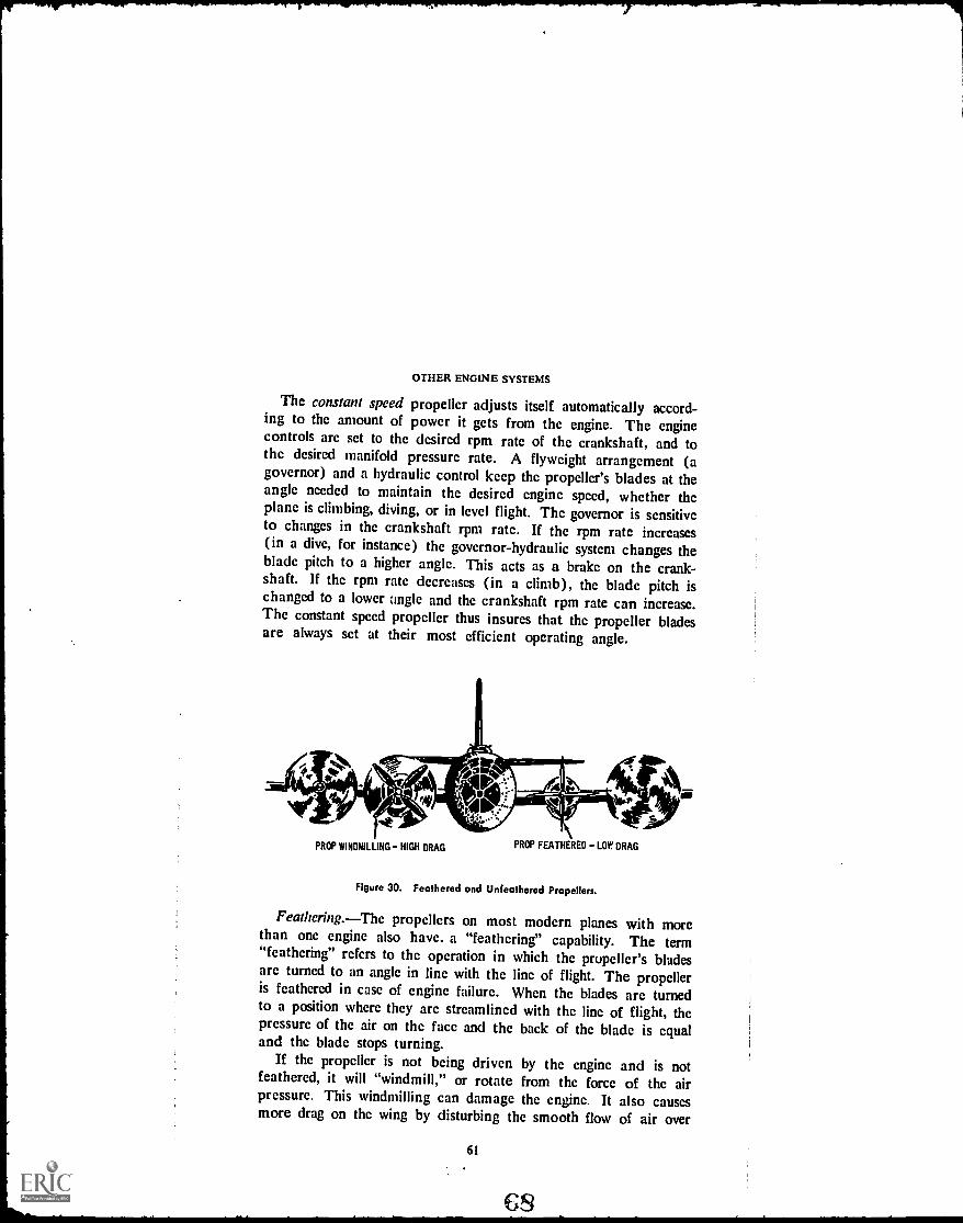
OTHER ENGINE SYSTEMS
The constant speed propeller adjusts itself automatically accord-ing to the amount of power it gets from the engine. The enginecontrols are set to the desired rpm rate of the crankshaft, and tothe desired manifold pressure rate. A flyweight arrangement (agovernor) and a hydraulic control keep the propeller's blades at theangle needed to maintain the desired engine speed, whether theplane is climbing, diving, or in level flight. The governor is sensitiveto changes in the crankshaft rpm rate. If the rpm rate increases(in a dive, for instance) the governor-hydraulic system changes theblade pitch to a higher angle. This acts as a brake on the crank-shaft. If the rpm rate decreases (in a climb), the blade pitch ischanged to a lower angle and the crankshaft rpm rate can increase.The constant speed propeller thus insures that the propeller bladesare always set at their most efficient operating angle.
PROP WINDMILLING HIGH DRAG PROP FEATHERED LOP DRAG
Figure 30. Feathered and Unfeathered Propellers.
Feathering.The propellers on most modern planes with morethan one engine also have. a "feathering" capability. The term"feathering" refers to the operation in which the propeller's bladesare turned to an angle in line with the line of flight. The propelleris feathered in case of engine failure. When the blades are turnedto a position where they are streamlined with the line of flight, thepressure of the air on the face and the back of the blade is equaland the blade stops turning.
If the propeller is not being driven by the engine and is notfeathered, it will "windmill," or rotate from the force of the airpressure. This windmilling can damage the engine. It also causesmore drag on the wing by disturbing the smooth flow of air over
61

PROPULSION SYSTEMS FOR AIRCRAFT
the wing. For this reason, the aircraft's working engine-propellerunits function more smoothly and efficiently when the propelleron a faulty engine is feathered (Fig. 30).
Reversible pitch. Most controllable pitch and constant speedpropellers also are capable of being reversed. In this process, thepilot rotates the propeller blades until he obtains a negative angleof pitch. This movement, coupled with increased engine power,reverses the propeller's thrust. The air is thus forced forward, awayfrom the aircraft, instead of rearward, over the wings. The reversi-ble thrust feature reduces the required landing run and saves con-siderably on brakes and tires.
Propeller efficiency.Airmen have p.cepted the fact that nopropeller will be 100 percent efficient. That is, no propeller canchange to thrust all of the energy supplied by the engine through thecrankshaft. This is true because some of the work done by theengine is lost to various other forces before it can be transformedinto thrust by the propeller.
The maximum efficiency that can be obtained by a conventionalpropeller operating in ideal conditions and in connection with aconventional engine is about 92 percent. But in order to obtain anefficiency that high, the blades of the propeller at the tip must bevery thin and the leading and trailing edges must be very sharp.These conditions have been found to be impractical for normaloperation. The most efficient propellers in every day use providesomething under 90 percent of full efficiency.
Two forces, thrust and torque, must be considered in rating theefficiency of the propeller. Thrust acts parallel to the axis ofrotation of the propeller, while torque operates parallel to the pro-peller's plane of rotation. Thrust and torque operate perpendicularto each other.
Thrust horsepower (the actual amount of horsepower that apropeller transforms into thrust) is less than the full amount of use-ful horsepower developed by the engine. Torque horsepower, how-ever, is about the same as the amount of useful horsepower theengine develops. Propeller efficiency is the ratio of thrust horse-power to torque horsepower.
Tip speed.A major limitation on the use of the reciprocatingengine in really high-speed flight is the fact that the speed of thetip of the propeller blade must be kept below the speed of sound.
62
69

OTHER ENGINE SYSTEMS
Generally, the speed of sound is 1,120 feet per second at sealevel, decreasing by about 5 feet per second for every :1,000 feet ofaltitude.
When the tip speed approaches the speed of sound, the propellerdevelops flutter, or vibration. Vibration causes strains to developand seriously affects propeller efficiency. A propeller whose tipspeed at sea level is 900 feet per second will deliver about 86 per-cent efficiency. But at 1,200 feet per second, the efficiency hasdropped to around 72 percent.
In modern, high-powered engine-and-propeller units, it is neces-sary to gear down the propeller to keep its tip speed below thespeed of sound. Were it not for this limitation, there is no reasonwhy an aircraft powered by reciprocating engines could not surpassthe speed of sound.
But science has not yet found a way to get around the pro-peller's tip speed limitation. To surpass the speed of sound, a differ-ent type of engine, loosely called the reaction engine, must be used.The term "reaction engine" includes both jet and rocket engines.Further, there are several different types of jet engines, and severaldifferent types of rocket engines.
Jet and rocket development lagged behind the development ofreciprocating engines prior to World War II. But since that time,the reaction engine has come into its own, expanding the limits ofspeed and altitude at which man can move.
Despite the numerical predominance of propeller-driven aircrafttoday, no modern survey of propulsion systems would be more thanhalf complete without considering the reaction engine.
REVIEW QUESTIONS
1. Name the five systems that make up the complete reciprocating engine.2. What are the advantages of the petroleumbased fuels used as aviation
fuels?3. What is the function of the carburetor?4. Why does the carburetor measure fuel and air by weight instead of by
volume?5. What is the function of the supercharger?6. What are the various types and functions of the lubricating system?7. How does the propeller provide thrust and lift to the aircraft?
63
PROPULSION SYSTEMS FOR AIRCRAFT
8. Name the parts of the propeller. What is the "plane of rotation?" The"effective pitch?"
9. What three forces act on a propeller in flight? Describe these forces.10. Why are propeller-driven aircraft incapable of supersonic flight?
THINGS TO DO
1. Recent incidents in the Middle East threatened America's supplies of oilfrom fields in that area. Find out and report on how much oil, gasoline,and other petroleum products are used in this country annually andwhere our sources of supply are located. Could the United States get alongwithout Middle Eastern oil supplies?
2. Recently, some automobiles have introduced the use of fuel injection intheir engine systems. Find out how these engines operate and report to theclass. See if any reciprocating aircraft engines are now using the fuelinjection system. What developments have made this use possible?
3. Helicopters are known in the military services as "rotary wing aircraft."Do some research on the helicopter and report on it, including compare Jnsof the helicopter rotors to wings and propellers of conventional aircraft(or "fixed wing" aircraft). Explain the theory behind helicopter flightand discuss its problems with torque, along with how these problemsare resolved.
SUGGESTIONS FOR FURTHER READING
CHAPEL, CIIARLES E., ed. Aircraft Power Plants. New York:Book Co., 1948.
MEIIRENS, HAROLD E.Patrol, 1958.
MCKINLEY, JANIES L.hides. New York:
McGraw-Hill
Power for Aircraft. Ellington AFB, Texas: Civil
and KALPII D. BERT. Powerplants for AerospaceMcGraw-Hill Book Co., 1965.
VAN DEVENTER, C. N. An Introduction to General Aeronautics.American Technical Society, 1965.
VAN Sloan, NEIL D. Modern Mortar:ship. Princeton, N.J.: D. Van NostrandCo., Inc., 1966.
Air
Ve-
Chicago:
64
voi.1

Chapter 4
Reaction Engines
A
THIS CHAPTER deals with reaction engines, with the emphasis on jetengines. It describes the operation of the jet in theory, givesexamples of how the different types of jet engines operate, andexplains the relative advantages of these engines. Rocket enginesare considered briefly, since they are the subject of fuller studyelsewhere in the Aerospace Education course. When you finish thischapter, you should be able to: (1) compare the operation andperformance of the jet and the reciprocating engine; (2) describe theoperational differences in the three main types of jet engines; (3)explain in some detail the operation of the turbojet engine; (4)describe such adaptations as the turbofan and the turbopropengines; and (5) explain solid and liquid rocket engines and howrocket fuel is rated.
WITH THE ADVENT of jet propulsion as a practical meansof powering aircraft, a whole new experience was opened to
mankind. The key word in this experience was "speed." Jet-pro-pelled aircraft were eyed with suspicion at first by a public whichhad become accustomed to seeing propellers on planes. But withexposure came acceptance, and the world was soon electrified tolearn that a manned, jet aircraft had flown beyond the speed ofsound.
JE1' ENGINES
Compared to the reciprocating engine and propeller combination,the workings of the jet engine are simple. In broad terms, the jet
65

PROPULSION SYSTEMS FOR AIRCRAFT
INTAKE VALVE BOTH VALVES BOTH VALVES
OPEN CLOSED CLOSED
INTAKE STROKE
RAM AIR DUCT
COMPRESSION
STROKE
COMPRESSOR
POWER
STROKE
FUEL INJECTION
EXHAUST VALVE
OPEN
EXHAUST STROKE
GAS TURBINE EXHAUST
NOZZLE
COMBUSTION
CHAMBERS
TAILPIPE
Figure 31. The Jet Engine and the FourStroke Cycle.
engine is essentially a tube in which the four-stage combustioncycle takes place. It is composed of an air intake section, a com-pression section, a combustion section, and an exhaust section (Fig.31).
Although the two different propulsion systems have much incommon when it comes to working principles, they are quite differ-ent mechanically. Both the jet and the reciprocating engine havetheir places in today's aviation, and they are well suited to theirdifferent uses.
The chief advantages of the jet-propelled aircraft are speed andthe ability to fly at high altitudes. The chief advantage of thereciprocating engine-propeller powered craft is economy at lowspeeds and at low altitudes.
Both systems get their power from the gases formed by burningfuel. Both depend on the air outside the engine for the oxygenneeded to burn the fuel. Both utilize the same basic laws of motion
66
ow 011..J

REACTION ENGINES
for their "push." Finally both use the four-stage cycle of intake,compression, combusion and exhaust.
But despite these similarities in the two engines, there arc twomajor differences. While the exhaust in the reciprocating engine ismainly wasted, the jet engine's exhaust is the force that makes theaircraft go. And the jet engine has no propeller.
Principles of Operation
The jet engine depends on Newton's second and third laws ofmotion for its operation. As we noted earlier, Newton's third lawstates that for every action, a reaction of equal force occurs in theopposite direction; Newton's second law says that force is equal tomass times acceleration.
Probably the most often-used illustration of Newton's third lawis the action of a balloon released with its neck open. The balloonzips around the room as air escapes from the open neck. The flightof the balloon is not caused by escaping air pushing against the airoutside the balloon, but by the reaction to that escaping air insidethe balloon.
The air rushing out of the balloon may be called the action.But inside the balloon, there is a reaction, just as strong, and inan opposite direction to the outrushing air. If our balloon had twonecks directly opposite each other, the air would rush out of bothopenings and the balloon would merely drop to the floor. Butsince there is only one neck, the balloon moves. This motion iscaused by the reacting air pushing against the inside surface of theballoon, in accordance with Newton's Third Law of Motion.
Newton's second law, applied to the jet engine, would mean thatthe force moving the aircraft (thrust) is equal to the mass (quantity)of air taken in through the front of the engine, multiplied by theacceleration (increase in speed) of that air before it leaves theexhaust nozzle at the back end of the engine.
You can sec, then, that the jet engine and the propeller bothprovide thrust by throwing quantities of air backward. In the jet,the air is channeled through a tube (the engine) of smaller diam-eter than the unconfined air in the propeller-type aircraft. Thismeans that a smaller mass of air is being moved by the jet engine.But in the jet, the acceleration of the moving air is much higherthan the acceleration of air being moved by a propeller. And since
67

PROPULSION SYSTEMS FOR AIRCRAFT
SPARK PLUG NOZZLE
CHAMBER
NOZZLES.'" FUEL"NOZZLES-
DIFFUSER SE TION COMBUSTION SECTION
A. POWER UNIT
FUEL ENTERSUNDER PRESSURE IGNITES
PLUG HOT WALLSOR RESIDUAL FLAMEIGNITES CHARGE
AIR FROM ATMOSPHERE
COMBUSTION DEVELOPSPRESSURE
B. OPERATION
PRESSURE LOSTIN FORMING
VELOCITY OF JET
Figure 32. The Ramjet, or "Flying Smokestack."
the velocity (the "action") of the air leaving the jet engine is verystrong, so is the thrust (the "reaction"). In this booklet, we willconsider past and present jet engine types, including the ramjet,pulsejet, turbojet, turboprop, and turbofan engines.
Ramjet
The simplest type of jet engine is the ramjet. With no moving
parts, the ramjet is little more than a tube fitted with fuel nozzles,and spark plugs to get it started. In fact, the ramjet has been de-scribed as a "flying smokestack" (Fig. 32).
The air is taken into the ramjet through the diffuser in the airintake section at the front of the tube. The diffuser is designed todecrease the velocity of the incoming air, thereby increasing its
pressure. (The total amount of energy in a mass, remember, must
68

REACTION ENGINES
remain the same.) This compressed air is channeled into the com-bustion section, where fuel is sprayed into it under pressure. Thespark plugs ignite the mixture.
The resulting explosion hurls the air forcefully out the exhaust,and the reaction to that force moves the engine forward. There isequal force exerted in all directions when the explosion occurs, ofcourse. But the high-pressure air in the diffuser blocks the expan-sion of the air forward; the walls of the engine and passing airblock the expansion outward; and the hot gases are forced out therear of the engine.
It should be pointed out that in jet engines, the spark plugs areused only to ignite the charge for the first time. The electric currentto the plugs is then cut off. The flow of air and fuel into the combus-tion chamber is continuous, and so is the flame. Thus, the chargefeeds itself fire. Instead of a series of fuel-air charges, as in thereciprocating engine, the jet engine has one continuous charge whichburns until the flow of air and/or fuel is discontinued.
The fire is held in the combustion chamber by a blocking devicecalled a flameholder. Otherwise, the fire would bz blown out therear of the engine with the exhaust gases and other a;r.
The ramjet cannot operate until it is moving at su.:;icient speedto bring about compression from the ramming air in the front of theengine (about 250 miles per hour). Aircraft using the ramjet musthave another type of propulsion to get them moving at that speedbefore the ramjet can be turned on. In theory, the speed attainableby the ramjet is unlimited, since the faster it goes, the more aircompression it gets; the more compression it gets, the more violentthe explosion in the combustion chamber; and the more violent thisexplosion, the more thrust is developed and the faster it goes. Inpractice, however, the ramjet's speed is limited to about five timesthe speed of sound (mach 5),* which is still a pretty fast clip. Thislimitation is due to friction-caused heat on the outside of the engineand the aircraft to which it is attached (called skin temperatures).Beyond mach 5, this friction heat would cause the metals now incommon use to melt.
The word "mach" is used to describe the speed of an object in relation to the speed ofsound in the same medium. The number accompanying the word "mach" indicates the mul-tiples of the speed of sound at which the objectin our case, the aircraftis traveling.At speeds below. but approaching, the speed of sound, numerals less than I may be used.Thus, an aircraft moving at mach .7 would be traveling at seventenths the speed ofsound. At mach 1, the aircraft would be moving at exactly the speed of sound. At mach2.5, the aircraft would be moving at two-and-a-half times the speed of sound. The speedof sound at sea level, in dry air at 32 degrees F, is about 1,087 feet per second (741miles an hour).
69

PROPULSION SYSTEMS FOR AIRCRAFT
Figure 33. Bomarc Missile Takes Off with Rocket Power, Shifts to Ramjet.
The ramjet engine is used in missiles, which are lifted off theground by another engine systemusually, a rocket engine. Justbefore the rocket engine burns out, the ramjet "kicks in" and takesover the job of powering the missile. Some examples of ramjet-powered 'missiles in use today are the Bomarc surface-to-air inter-ceptor missile and the Redhead/Roadrunner guided target missile(Fig. 33).
A late development in ramjet engines is capable of hypersonicflight; that is, flight at speeds above mach 5. This engine is calledthe "scramjet," and may be used in the future on aircraft designedto cruise at hypersonic speeds, on recoverable launch vehicles, andon defense missiles.
Pulse Jet
The pulsejet is only slightly more complex than the ramjet, butit is much less useful in modern aviation. It has a diffuser, a grillassembly, a combustion chamber, and a tailpipe. Air feeds through
70

REACTION ENGINES
the diffuser, just as in the ramjet, and through the grill to the com-bustion chamber.
The grill is a honeycomb of air valves which allow the air toflow through if the pressure in the diffuser chamber (intake) isgreater than the pressure in the combustion chamber. These airvalves arc spring-loaded in the closed position and open inward,toward the combustion chamber.
When the air is allowed into the combustion chamber, a fuelcharge is injected and the fuel-air charge is ignited. The force ofthe resulting explosion closes the air alves in the grill and forces theexhaust out the tailpipe. When the pressure of that charge lessens
Figure 34. Operating Cycle of the Pulsejet Engine.
71
t-.40111,
C L.7
1

PROPULSION SYSTEMS FOR AIRCRAFT
in the combustion chamber, the valves open again and more airmoves into the combustion chamber. The cycle repeats, with theignition of the second charge coming from the flame of the firstcharge, feeding back (Fig. 34).
Pulsejets powered the German V-1 missile in World War II. Thecharacteristic noise produced by the pulse jet was responsible forthe V-1's nickname of "buzz bomb."
Although the pulsejet is simple and inexpensive to build, its speedis limited. At air speeds above mach 0.6 (slightly over half thespeed of sound), the pressure in the diffuser section holds the airvalves open too long for efficient operation. Because it cannotcompete effectively against the reciprocating engine on the one handand more advanced jet engines on the other, the pulsejet has nearlyvanished from the aviation scene.
COMBUSTION CHAMBER AFTERBURNER
Figure 35. Turbojet Engine, with Afterburner in Exhaust Section.
The Turbojet
The turbojet engine, the most widely used engine in the jet worldtoday, uses the same principles used by the ramjet and the pulse-jet, but is a much more refined and practical machine.
Employing the combination of gas turbine and air compressor, theturbojet is its own master. It can start from a dead stop and canpower aircraft to more than twice the speed of sound.
There are many models and several modifications of the turbojetengine, but they all share the same basic operational sequence:air enters through the air intake section (diffuser); goes throughthe mechanical compressor, where its pressure is greatly increased;is forced into the combustion chambers, mixed with fuel, andburned; and escapes as high-velocity gases out the exhaust nozzle,producing thrust (Fig. 35).

REACTION ENGINES
Between the combustion chambers and the exhaust nozzle, thereis a turbine. The exhaust gases turn the turbine wheel just as windturns the wheel of a windmill. The turbine is connected by a directshaft to the compressor. The rotation of the turbine operates thecompressor, which sends more air through the engine to turn theturbine.
The compressor section of the turbojet is the area where the air iscompacted in preparation for burning. It corresponds to the re-ciprocating engine's cylinder in the compression stage. Turbojetengines are generally classified as centrifugal flow or axial flowengines. These terms refer to the design of the air compressor inthe engine, and the way the air flows through it.
Centrifugal flow engines.The centrifugal flow compressor iscomposed of a rotor, a stator, and a casing. The rotor is mountedwithin the stator, and that whole assembly is enclosed in the casing.
STATOR"OK:
4101
ROTOR
Figure 36. Centrifugal Compressor, Without Casing.
73
SO

PROPULSION SYSTEMS FOR AIRCRAFT
The casing has an opening near the center for the air to enter(Fig. 36).
The rotor is made up of a series of flat blades. The blades re-volve, take the air in, and whirl it around, increasing its velocity.Centrifugal force causes the air to move outward from the center tothe rim of the rotor blades, where it is thrown out of the wheel andinto the stator with considerable velocity.
The stator consists of diffuser vanes, or blades, which curl outfrom the central axis of the rotor. The stator does not rotate. Themoving air acquires energy, in the form of velocity, in the rotor.This energy is converted to pressure energy by the stator. As the airmoves through the stator's diffuser vanes, it loses velocity and ac-quires pressure (since the total energy of velocity and pressure mustremain the same).
COMPRESSED GASES ARE
FED INTO ENTRY OFFOLLOWING STAGES
FIRSTSTAGE
SECOND THIRD FOURTH
STAGE STAGE STAGE
Figure 37. Multistage Compressor gets more Air Compression.
From the stators, the compressed air is fed into the combustionchambers.
Each set of rotors and stators is called a stage. A single stagecentrifugal flow compressor will produce a compression ratio ofabout four to one. That is, it will reduce a given mass of air toabout one-fourth the volume it had in its free state.
Additional stages will improve the compression ratio somewhat(Fig. 37). But much of the potential energy of the air mass inthe centrifugal flow compressor is lost through drastic changes indirection caused by centrifugal force. For this reason, most jet en-gines made today employ the more efficient axial flow compressor.
74
01

GASESACQUIREENERGY
OFMOTION
Figure 38. Single Stage Operation of the Axial Compressor.
1... ROTATION
Arfor,..
(151111121."--<,s.
440v-,.
ROTOR STATORBLADES BLADES
STATORBLADES
2.
Figure 39. Stators in Axial Flow Compressor Straighten Airflow.
75
S2
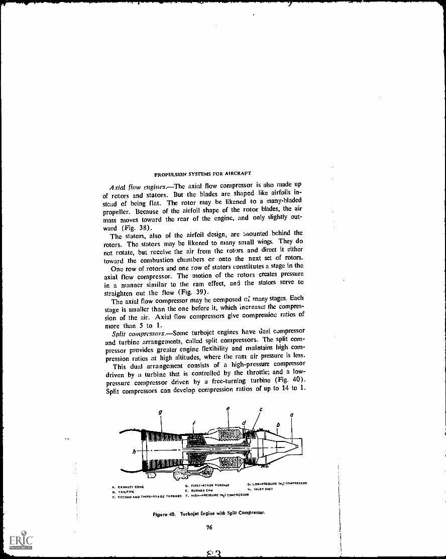
PROPULSION SYSTEMS FOR AIRCRAFT
Axial flow engines.The axial flow compressor is also made up
of rotors and stators. But the blades are shaped like airfoils in-
stead of being flat. The rotor may be likened to a many-bladed
propeller. Because of the airfoil shape of the rotor blades, the airmass moves toward the rear of the engine, and only slightly out-ward (Fig. 38).
The stators, also of the airfoil design, arc inounted behind therotors. The stators may be likened to many small wings. They do
not rotate, but receive the air from the rotors and direct it either
toward the combustion chambers or onto the next set of rotors.One row of rotors and one row of stators constitutes a stage in the
axial flow compressor. The motion of the rotors creates pressurein a manner similar to the ram effect, and the stators serve tostraighten out the flow (Fig. 39).
The axial flow compressor may be composed cc many stages. Each
stage is smaller than the one before it, which increases the compres-
sion of the air. Axial flow compressors give compressioi ratios of
more than 5 to 1.Split compressors. Some turbojet engines have dual compressor
and turbine arrangements, called split compressors. The split com-
pressor provides greater engine flexibility and maintains high com-
pression ratios at high altitudes, where the ram air pressure is less.
This dual arrangement consists of a high-pressure compressordriven by a turbine that is controlled by the throttle; and a low-
pressure compressor driven by a free-turning turbine (Fig. 40).Split compressors can develop compression ratios of up to 14 to 1.
a
A. EXHAUST CONE 0. FIRST-STAGE TURBINE G. LOW-PRESSURE IN,I COMPRESSOR
D. TAILPIPE E. BURNER CAN H. INLET DUCT
C. SECOND AND THIRD-STAGE TURBINES F. HIGH-PRESSURE oy COMPRESSOR
Figure 40. Turbojet Engine with Split Compressor.
76

REACTION ENGINES
At high altitudes, the air is thin and the ram pressure in thefront of the engine is therefore reduced. But a free-turning com-pressor takes advantage of the thin air's lesser resistance on its rotorblades, and turns faster, bringing in greater volumes of air. Thisarrangement enables the free compressor to keep the high-pressurecompressor supplied with air.
The split compressor illustrates how theory and practice do notalways agree. In theory, a single axial flow compressor with manystages could develop an unlimited amount of compression. But inpractice, this is true only at a certain engine speed. At other speeds,the smaller stages toward the rear of the compressor lose efficiencybecause they cannot handle the large volumes of air being suppliedby the larger stages toward the front. As a result, the front sectionsbecome overloaded and turbulence results. This turbulence inter-feres with the effective angle of attack of the airfoil-shaped rotorsand stators, and the result is compressor stall.
INNER LINER DOME SPARK PLUG OUTER CHAMBER?INNER CHAMBER
var_ ..,,,I,..r,'''''''i_,40000.....lil41, 1pi e- , L. L L l L, L
6... L., L..
''' - ; --A' ----11,110416614011 111111allr.
`-;------ Agl. . kL-.1r6 -----'-'7P ---rNirFUEL NOZZLEMID FRAME
CROSS-OVER TUBEDRAIN EXPANSION BELLOWS
Figure 41. Jet Engine Combustion Chamber.
With the split compressor, the rearmost stages are large enough tohandle the larger volumes of air without loss of efficiency.
Combustion chambers.On leaving the compressor, the air is
forced into the combustion chambers, mixed with the fuel, andburned in the continuous combustion process. Jet engines canoperate on a wide variety of fuels, but refined kerosene has beenfound to be the most satisfactory fuel available so far.
Only about one-fourth of the air from the compressors is used forcombustion. The rest of the air is channeled around the outsideof the combustion chambers, or around the fire inside the combus-tion chambers, for cooling purposes.
77

PROPULSION SYSTEMS FOR AIRCRAFT
Ordinary turbojet engines may have 14 separate combustionchambers in their combustion section, divided so that the coolingair can be more effective.
The combustion chamber includes an inner chamber, where theactual burning takes place; an outer chamber; a fuel nozzle; andcrossover tubes (Fig. 41).
Temperatures in the inner chamber get above 3,000 degreesFahrenheit. But these temperatures never reach the wall of theinner chamber. The burning is centered in the chamber throughcareful design, and is surrounded by a blanket of air that is, ofcourse, hcated, but does not burn. All of the burning must be com-pleted before the exhaust leaves the inner chamber, because theintense heal of the burning charge could severely damage the turbinewheel.
Air rough the liner between the inner and outer chambers.The outcr chamber keeps a supply of high-pressure air available tothe inner chamber for cooling.
The fuel nozzle sprays the proper amount of fuel into the innerchamber, using the fuel injection system. The fuel spray is underpressure at about 700 pounds per square inch, and the fuel flow isregulated to achieve an air-fuel ratio of about 14 to 1.
Usually, only two spark plugs serve the entire combustion sys-tem, and then only for the initial ignition. After the engine is startedand the spark plugs have ignited the fuel-air mixture, the plugs areturned off.
The crossover tubes connecting the combustion chambers feed theinitial flame into those chambers without spark plugs. After theflame is introduced into all the chambers, the burning process feedsitself. The high-pressure air blanket then blocks off the openings inthe crossover tubes before temperatures mount very high.
Turbine section.The hot exhaust gases and unburned air leavethe combustion section through a nozzle diaphragm, which increasestheir velocity to about 2,000 feet per second and directs them ontothe turbine wheel blades.
The turbine wheel is the toughest part of the jet engine. It hasto be, to withstand the tremendous temperatures and other stresseson it.
The temperature of the gases striking the turbine wheel bladesmay reach 1,500° F., and the wheel rotates at about 1,200 revolu-tions per minute. These stresses were a serious problem to early
78
0c.t"-(.2.

REACTION ENGINES
STATOR ROTOR
Figure 42. Single Stage Turbine.
developers of the turbine. But recent advances in metallurgy (thescience of metals) have produced metal alloys capable of withstand-ing the strains of heat, shock, and centrifugal force for 1,000 hoursor more of operation.
Like the compressor, the turbine wheel may consist of one ormore stages. And like the compressor, the turbine is composed of al-ternating rows of stators (the nozzle diaphragm) and rotors (theturbine wheel blades).
The shaft attached to the center of the turbine is connected atthe other end to the compressor, which it drives (Fig. 42).
Exhaust .section. The gases exit the turbine at temperatures ofabout 1,200° F. and speeds of about 1,200 feet per second and enterthe exhaust nozzle. This nozzle has an inner cone, supported bystruts. Together, the nozzle, cone, and struts straighten out the flowof the gases leaving the revolving turbine wheel, and send these gasesthrough the tailpipe (Fig. 43).
The tailpipe is designed to increase the velocity of the gases to apoint where they furnish maximum thrust without causing the engineto overheat. As the gases leave the tailpipe, their temperature has
79 c"-)C(...\

GAS TURBINEROTOR BLADES
PROPULSION SYSTEMS FOR AIRCRAFT
Figure 43. Exhaust Section and Tailpipe.
dropped to about 1,000° F. and their velocity has increased to 1,800feet per second or more.
Remember, the velocity of the gases leaving the tailpipe is an im-portant factor in the thrust-determining equation, Force = Masstimes Velocity.
The afterburner. Sonic turbojet engines, principally on militaryaircraft, arc equipped with devices which increase the velocity ofthe exhaust gasesand thereby, increase thrustwhen maximumperformance is required.
This device, aptly called the afterburner, acts in the manner of asmall ramjet engine when it is in use and as a tailpipe when not inoperation (Fig. 44).
TURBOJETTURBINE
FLAMEARRESTOR
TURBOJET
ENGINE
FUELNOZZLESDIFFUSER
EXHAUSTCOMBUST.
CHAMBER
2 \( SHUTTERS
VARIABLEAREANOZZLE
Figure 44. Turbojet Engine Equipped with Afterburner.
80

REACTION ENGINES
Since a large amount of the air that enters a turbojet engine isused for cooling and not for burning, there is ample oxygen in theexhaust air to operate the afterburner. As in the ramjet, fuel isinjected into the afterburner under pressure. The exhaust gases fromthe main engine are of high enough temperature to ignite the fuel oncontact, and the resulting burning greatly increases the exhaustvelocity from the afterburner.
The afterburner is fitted with flameholders to keep the high-speed exhaust gases from blowing the burning gases out of thechamber.
-r
Figure 45. B-52 Bomber and Hound Dog Missiles are Powered by Turbojet Engines.
The turbojetwith or without the afterburnerhas become themost widely-used type of jet engine. It is found supplying the powerfor many different types of aircraft, from fighters to bombers andpassenger planes to guided missiles. Some examples of the aircraftusing the turbojet engine for power are the F-105 Thunderchief, aworkhorse for the United States in Vietnam; the F-5 FreedomFighter, used by a number of nations as a primary defensive air-
81
41)

Al R
Lo L
PROPULSION SYSTEMS FOR AIRCRAFT
COMPRESSOR FUEL SPRAY COMPRESSORDRiVE TURBINE
REDUCTION GEAR COMBUSTOR TAIL CONE
PROPELLER PROPELLERDRivE TURBINE
Figure 46. The Turboprop Engine.
craft; the B-52 bomber; some versions of the Boeing 707 and 720and the Douglas DC-8 passenger aircraft, used by commercial air-lines; the Hound Dog air-to-ground missile; and the mach 3-plusSR-7I strategic reconnaissance plane (Fig. 45).
The Turboprop Engine
Experience has shown that jet-powered aircraft are superior topropeller-driven aircraft at high speeds and high altitudes, while thepropeller-driven planes excel at comparatively low speeds and lowaltitudes. In fact, the turbojet engine does not equal the reciprocat-ing engine-propeller system in efficiency until speeds of nearly 400miles per hour are reached.
In an effort to combine the best features of both systems, enginedesigners developed the turboprop engine. As the name implies, thisengine uses a gas turbine-powered propeller for its drive.
In the turbojet engine, most of the gases passing through the com-bustion chamber are forced out the tailpipe to produce thrust. Onlya small amount of the energy of these gases is used to turn theturbine and compressor.
But in the turboprop engine, the reverse is true. The turbine inthis engine is designed to absorb almost all the energy from the ex-haust gases. Part of this energy turns the compressor, allowing theengine to function in essentially the same manner as the pureturbojet.
But the bulk of the energy is passed from the turbine to the pro-peller, which is mounted at the front of the engine (Fig. 46). The
82
g9

REACTION ENGINES
turboprop has a weak exhaust from its tailpipe. Turboprop-poweredaircraft obtain their thrust from the propeller, which moves a largermass of air than would the turbojet, but at a lower velocity.
Strictly speaking, the turboprop system is not a jet engine (itsthrust is not produced by high-velocity exhaust gases), but a pro-peller driven by a gas turbine engine.
The gas turbine engine can supply the propeller with double thehorsepower of the conventional reciprocating engine. But reductiongearing must be used to slow the rpm rate of the propeller andkeep its tip speed below the speed of sound. All the limitations ofthe propeller still apply to the turboprop engine.
A number of engine manufacturers and aircraft users have ac-cepted the limitations of the turboprop enginealong with its bene-fitsand the engine is seeing extensive use today.
Among the aircraft using the turboprop system are the C-130Hercules and the C-133 Cargomaster, both cargo planes built byDouglas Aircraft; the Lockheed Electra; and the Convair 580, nowbeing used by at least three airlines, more than a dozen corporations,and the Federal Aviation Administration.
But engine manufacturers have not stopped with that compromisebetween the propeller craft's superiority at low speeds and the jetengine's class at high speeds. Continuing experimentation and de-sign changes have produced a much better "compromise" than theturboprop engine. This newest development is an improved turbojetcalled the turbofan engine, and may become the dominant enginebefore long.
Turbofan Engine
The turbofan engine, also called the ducted fan or bypass engine,is of more recent development than the turboprop engine. It sharesthe turboprop's principle of moving larger volumes of air at lowervelocities, but is still strictly a jet engine.
In the turbofan engine, one or more rows of the compressor bladesare extended beyond the length of the rest of the compressor blades.These elongated blades pull large volumes of air through ducts out-side the power section of the engine (Fig. 47).
A normal amount of air is fed through the combustion chambers,the turbine, and the exhaust section. But the air pulled by the ex-tended blades (the fan) is ducted outside the engine so that it by-
83

PROPULSION SYSTEMS FOR AIRCRAFT
passes the combustion chamber, is forced backward, and is dis-charged without burning. It is discharged with the exhaust gases.
In one respect, the turbofan's extended compressor blades (itsfan) resemble the action of the propeller in the turboprop engine.But the fan is run directly by the turbine, without the necessity ofreduction gearing, and it is not subject to the propeller's speedlimitations.
The turbofan engine moves up to four times as much air as thesimple turbojet. It is capable of driving an aircraft at supersonicspeeds without the benefit of an afterburner.
An innovation in the turbofan engine allows burning of the air inthe fan stream. This type of engine, called the fan burner, is es-sentially a turbofan engine with an afterburner capability. Econom-ical operation can be obtained from this engine at low altitudes
FANCOMBUSTION HIGH SPEED &
LOW PRESSURE HIGH PRESSURE CHAMBERLOW SPEED TURBINECOMPRESSOR COMPRESSOR
Figure 47. The Turbofan Engine.
and low speeds if the extra burner is not used. At high altitudesand high speeds, the burner may be used without too much loss ofefficiency and economy. Burning fuel in the fan duct of this enginecan double the normal thrust of the turbofan -engine.
Compared to the more conventional turbojet, the turbofan enginefurnishes greater thrust for take-off, climbing, and cruising from thesame amount of fuel, mainly due to its larger air movement. Theaddition of the afterburner capacity has boosted the popularity ofthe turbofan. Some of the outstanding aircraft now using this kindof engine are the famed F-4 Phantom, used by the Air Force, theNavy, and the Marines; some versions of the B-52 bomber; theKC-135B tanker aircraft; the commercial airlines' Boeing 727 andDouglas DC-9, plus some versions of the Boeing 707; the C-141Star lifter cargo plane; and the new A-7 Corsair II attack aircraft.
84

REACTION ENGINES
A look at that list will show the variety of uses of these aircraft. andthe versatility of the turbofan engine. Very powerful turbofan enginesalso will drive America's supersonic transport (SST), now in de-velopment.
Noise Suppressors
Since they first came into use, jet-powered aircraft have beennoted for the loud, objectionable noises they make. These noises inthe conventional turbojet are caused by the movement of the high-velocity jet stream (exhaust) moving through the relatively quiet,still air around it. The sound of the high-speed air is of low fre-quency, and travels farther than would a higher-pitched sound ofthe same initial intensity. These loud noises are more of a nuisancethan a real threat; they annoy passengers in the aircraft and peopleon the ground, particularly people who live near airports. But sus-tained, loud exhaust noises also can have a bad effect on the ef-ficiency of the crew.
To curb these noises as much as possible, exhaust silencers havebeen put into use on some turbojet engines. These noise sup-pressors break up the large exhaust stream into smaller streams. Thisdivision raises the sound frequency of the smaller streams so thatpart of the noise is thrown outside the range of human hearing. Therest of the noise dissipates quickly, so that the sound does not "carry"as far.
Thrust Reversers
One big problem in the Use of jet aircraft is the need for longrunways for landing. The thrust force of the jet cannot be re-versed in the same manner as the thrust of the propeller.
Early attempts at braking the jet aircraft made use of a parachute,which would, when released by the pilot, flare out behind the air-craft. The drag caused by the parachute slowed the plane downand reduced the required length of the landing strip.
But the parabrake, as it was called, was not entirely satisfactory.For one thing, its braking power could not be controlled by thepilotit was all or nothing, since the parabrake would open fullywhen released. For another thing, the parachute had to be repackedafter each use.
85
c,

PROPULSION SYSTEMS FOR AIRCRAFT
CASCADE VANES
BLOCKER DOORS
nnREVERSING GATE iik,
'AUL'
THRUST
THRUST REVERSER SLEEVE
CASCADE VANES
Figure 48. Turbofan Engine During Normal Flight (top) and with Fan and Aft ThrustReverser in Operation (bottom).
TAIL 'IPE
EXHAUST DEFLECTOR
FORWARD THRUST POSITION REVERSE THRUST POSITION
Figure 49. Simple Tailpipe Thrust Reverser, Showing Forward and Reversing Positions.
86

REACTION ENGINES
Two types of mechanical thrust reversers have been devised andare in use on some jet aircraft today. These reversers are used onaircraft equipped with turbofan engines and in some turbojet-poweredaircraft. One of these reversers affects the airstream in the bypassduct in front of the engine and at the exhaust nozzle in the rear.The other reverser affects only the exhaust gases.
The "aft" part of the fan and aft reverser is connected to theexhaust nozzle in the tailpipe section of the engine. Its three princi-pal parts are a set of clamshell-type doors, called reversing gates,inside the tailpipe; a set of vaned openings, called cascade vanes,in the side of the engine; and a sliding sleeve which covers thecascade vanes until the thrust reverser is activated (Fig. 48).
When the fan and aft thrust reverser is activated, the sleeve slidesrearward, opecti;fg the cascade vanes on the side of the engine. Thereversing gates swing shut, blocking the straight rearward thrust ofthe exhaust gases and forcing them out the cascade vanes, at anangle slightly forward of perpendicular to the straight rearward flow.
At the same time, blocker doors in the front of the fan sectionmove into the duct, forcing the bypass air to reverse at about thesame angle (see Fig. 48).
Another type of thrust reverser, operating only at the rear of theengine, has exhaust deflectors mounted on the outside frame of thetailpipe section. It can be used on turbojet as well as on turbofanengines. When this reverser is activated, the doors swing shut andthe exhaust gases are diverted slightly forward. On this type ofreverser, the doors are mounted externally; there arc no cascadevanes; and there is no sliding sleeve. When this reverser is notoperating, the deflectors form an extension of the tailpipe (Fig. 49).
Use of the mechanical thrust reverser allows the pilot to maintainfull engine power while landing. Maximum thrust can be obtainedimmediately, in case the pilot has to pull out of his planned landing,by retracting the thrust reverser.
Accessory Section
The accessory section of the turbojet houses the engine's electricstarter, generator, oil and fuel pumps, hydraulic pumps, and otheraccessories important to the engine.
The accessory section is housed in the front center of the engine,between the air intake section and the compression section. It iscovered by the diffuser cone.
87

PROPULSION SYSTEMS FOR AIRCRAFT
Water Injection
Many jet engines are fitted with water injection systems whichcan spray water into the combustion chambers as a means of in-creasing mass airflow through the engine. The water not only addsits own mass to the flowing matter, but cools the engine temperaturesso that more fuel is burned in an attempt to bring the engine backto normal operating temperatures. The extra fuel increases theintensity of the explosion in the combustion chamber, and increasesthe velocity of the exhaust gases.
The tailpipe section also is affected by the cooling effects of waterinjection on the exhaust gases. Many tailpipes have automaticallyregulated orifices, or openings, through which the exhaust gasesescape. As the temperatures of the gases drop, the tailpipe orificecloses somewhat as a means of bringing the temperature of thegases back to their most efficient heat. When the tailpipe openingis thus constricted, the velocity of the exhaust gases increases, andthrust increases with it.
Metals
Despite dramatic advances in metallurgy, the chief limiting factorin the further development of jet engines is the lack of materialscapable of standing up under the jet's high temperatures and windvelocities.
Currently, more than 25 different alloys, or blends of metals,are being used in jet construction. These metals, exposed to theheat in the jet engine, are called "refractory metals."
The alloys usually have as bases either chromium, nickel, cobalt,or tungsten, or combinations of those elements. Titanium is usedwhere temperatures do not get above 700 degrees F.
Comparisons
Some of the disadvantages of the turbojet engine today, as com-pared to the reciprocating engine-propeller combination, are: highfuel consumption at low speeds; high materials costs, both in manu-facture and in maintenance; cxterior noise; length requirements forair strips used; and the possibility of damage to the engine from ob-jects sucked into the air intake.

REACTION ENGINES
Continuing research and development, however, promises to caseall or at least some of these problems. The jet engine. remember.is still a relative infant.
The turbojet's advantages over the "conventional" engine include:freedom from vibration, since all the moving parts rotate instead ofreciprocate; simplicity of design and operation; less interior noise;higher thrust-per-pound ratios; higher speeds; and reduced firehazards, since the fuels used in jet engines arc less volatile.
ROCKETS
The rocket is another. type of reaction engine, sharing with thejet engine an operating principle based on Newton's Third Law ofMotionequal and opposite reaction. But an important differencein the jet and the rocket systems is that the jet is an air-breathingmachine, dependent on atmospheric air for the oxygen that enablesits fuel to burn. The rocket carries its oxidizer along with it.This means that the rocket is not dependent on atmospheric oxygen,and can operate where there is no oxygen in the airin outer space,for instance.
In some cases of everyday use, the words "rocket" and "missile"are used to mean the same thing. For the purposes of this study,however, "rocket" will be used in reference to the propulsion systemonly, and "missile" will mean the complete vehicle.
Missiles, while usually powered by rockets, may be powered byother means. An example is the previously mentioned V-1 missile(the "buzz bomb"), which was powered by a pulse jet. A numberof military missiles developed since World War II also are poweredby air-breathing jet engines.
The principle parts of the rocket-powered missile are the rcckctengine, the propellants (including fuels and oxidizers),, the air-frame, or body of the missile, and the payload, or cargo. The pay-load may be nearly anything, including scientific instruments, explo-sives, or men.
The rocket engine provides thrust by ejecting hot, gaseous ma-terials from the missile's exhaust nozzle at high velocities. Thesource of these gases is the propellant, which may be either liquidor solid. The propellant may be changed to the gaseous statethrough any of a number of processes, but the most commonmethod in use today is chemical combustion.
89

PROPULSION SYSTEMS FOR AIRCRAFT
Rocket Classification
Rocket engines are generally classified by the type of fuel theyuse, liquid or solid. Thcrc arc advantages to both types. Generallyspeaking, the liquid propellants are capable of producing morethrust per pound than are the solid propellants, while the solid fuelrockets use simpler engine systems.
Solid rocket.In the solid propellant rocket, the fuel and oxidizerchemicals usually are mixed together and cast in a solid mass. Thismass is called a grain.
The grain is cemented to the inside walls of the metal or plasticcombustion chamber. It is cast with a hole down its center. Thehole may be of any of a variety of shapes, but star, circle, and gearshapes are most commonly used.
The size and shape of the hole in the grain affects the burningrate of the fuel, and thus the rate at which the gases are expelled.
Coe* wall
is
Nettle
Figure 50. Diagram of a Solid Fuel Rocket.
The grain is ignited, usually with an electrical device, and burnson the entire inside surface. 'the gases produced by this burningrush down the hole to the c:thaust nozzle, where they are dis-charged at tremendous velocities to produce thrust (Fig. 5C).
The propellant grain usually consists of one of two types of chemi-cal. Onc type is the double-base chemical, consisting largely ofnitroglycerine and nitrocellulose. This propellant resembles smoke-less gunpowder.
The other type of solid chemical in use is the composite pro-pellant. The composite propellant is more widely used today thanthe double-base. It consists of an oxidizing agent, such as am-monium nitrate or ammonium chlorate, mixed with an organic or ametallic fuel. Many of the fuels are plastics.
90

REACTION ENGINES
Thrust from the solid propellant rocket may be stopped on com-mand through two methods: blowing off the exhaust nozzle oropening vents in the combustion chamber walls. Both methodscause the pressure in the chamber to drop, and extinguish the flame.Solid fuel rockets power a number of America's guided missiles,such as the Polaris and Poseidon submarine-launched missiles,Honest John, Little John, Minuteman, and a number of larger andsmaller missiles. Solid rockets also are used as boosters in some
space-probing missiles.In some instances where the large missiles are concerned, solidrockets arc used in combination with liquid rockets. This practice
will be explored later in this chapter. But generally speaking, theliquid rockets are more powerful, pound for pound, and arc easierto control. Both factors must be considered when real live huma,tbeings arc riding the nose of these missiles.
011dIzertank
It
Pump Turbine
Gasgenerator
Fulltank
I I
Pump
Vol'
Tbrusl chamber
Pump -fed meet
OxidiserTank
(0) Prisms -led rocket
Figure 51. Pump-fed and Pressurefed Liquid Fuel Rocket Diagram.
91

PROPULSION SYSTEMS FOR AIRCRAFT
Liquid rocket.Liquid-burning rocket engines are composed oftanks for fuel and oxidizer, lines from both tanks, pumps, a thrust(combustion) chamber, and an exhaust nozzle.
The common liquid rocket uses a liquid fuel and a liquid oxidizer,and is thus termed bipropellant. The fuel and the oxidizer (usuallyliquid oxygen) are contained in separate tanks and are mixed onlyupon injection into the thrust chamber. If the flow of either the fuelor the oxidizer is interrupted, combustion will stop.
The fuel and the oxidizer may be fed into the combustion cham-ber by pumps or by pressure within their tanks (Fig. 51).
In high-thrust engines, hundreds of gallons of propellant mustflow into the combustion chamber every second. In these engines,the propellant is delivered by pumps, and the pumps are usuallypowered by a gas turbine (see Fig. 51).
The turbine is driven by a gas generator, which is actually asmall combustion chamber whose exhaust gases are directed intothe turbine wheel. Shafts from the turbine wheel drive the fuel andoxidizer pumps. The gas generator that drives the turbine uses thesame propellants as the main rocket engine.
In the pressure feed system, the pumps are removed and thepropellants are forced out of their tanks and into the combustionchamber by gas pressure of up to 500 pounds per square inch.
The pressure feed system is simpler and, perhaps, more reliablethan the pump system, but it has its disadvantages. To withstandthe high pressures, the tanks must be built of very heavy materials,which add additional dead weight to the missile. In many cases, thisdead weight more than offsets the advantages obtained by removalof the pump system.
As in the solid propellant rocket, the exhaust nozzle of the liquidrocket is subjected to very high gas temperatures and velocities.The nozzle of the liquid fuel rocket is cooled by the propellant itself.Prior to injection into the thrust chamber, the propellpnt feedsthrough a system of passageways in the walls of the nozzle. This iscalled regenerative cooling.
In the liquid fuel rocket, the amount of thrust can be governed bymeans of valves which control the amount of propellant flow. Thrustcan be stopped by closing the valves and blocking the propellantflow.
Some liquid fuel rockets use hypergolic propellants. A hypergolicpropellant is a fuel that will ignite spontaneously when it comes into
f::;49 92

REACTION ENGINES
contact with an oxidizer. The word hypergolic is derived from"hypergol," a World War II German code name for these fuels.
Some of the most famous of American missiles have been poweredby liquid rockets. These missiles include those used in the mannedMercury project, in which single men were sent into space by way ofAtlas launch vehicles; the manned Gemini project, where two-manteams were sent up on Titan missiles; and in part of the giant Saturnmissile, used in the three-man Apollo project. Also in the liquidrocket category is the Delta missile, used to put up a number ofcommunications satellites including Early Bird, Telstar, Relay, andSyncom.
Propellants and Thrust
Now that we have an idea of how the liquid and solid fuelrockets operate, let us look at the methods scientists use to evaluatethe power of these fuels.
Specific impulse.The performance measurement of a rocketpropellant is called the propellant's specific impulse. The unit ofspecific impulse is the measure of the number of pounds of thrustproduced by each pound of propellant burned in one second(pounds of thrust/pound of fuel/second).
For simplicity, specific impulse is stated in "seconds." Thus, inthe case of a chemical propellant with a specific impulse of 300seconds, every pound of the chemical burned in one second woulddeliver 300 pounds of thrust through the exhaust nozzle.
Chemical propellants in use today have specific impulse ratingsranging from 175 to about 300 seconds. Theoretically, the mostenergetic chemical propellant would be capable of specific impulsesup to 400 seconds.
The velocity that a rocket can attain is proportional to the specificimpulse of its propellants. For example, if a given rocket can reacha speed of 10,000 feet per second with propellants delivering aspecific impulse of 250 seconds, the same rocket would reach aspeed of 11,000 feet per second (a 10 percent increase in speed)if the propellant's specific impulse were 275 seconds (a 10 per-cent increase in specific impulse).
Thrust requirements.Vertical takeoff from the Earth requiresa thrust that exceeds the total weight of the rocket-powereci missileand its propellants by 30 to 50 percent. For example, a missile
93 100

PROPULSION SYSTEMS FOR AIRCRAFT
weighing 1,000 pounds would have to develop between 1,300 and1,500 pounds of thrust before it could take off straight upward.
Rocket engines usually burn their propellants at a constant rate,and thus develop a constant rate of thrust, during their entire burn-ing time. But as the fuel burns, the total weight of the missile de-creases by the amount of weight of the fuel that has burned. Thismeans that although the amount of thrust is the same, the enginehas less weight to move. So the speed of the missile increases con-stantly, up to the time the last bit of fuel burns. At this point,the missile will either fall back to earth; go into orbit around theearth; or continue in a straight line into space, depending on thefinal speed of the missile and the angle at which it is traveling.
Escape velocity.The amount of speed required to get beyondthe gravitational pull of a planet or other cellestial body is called theescape velocity. Escape velocity varies for the different planets, andis dependent on the mass of the planet and the distance from thecenter of the planet to the space vehicle (Fig. 52).
The speed required to escape into space from the surface of theEarth is about 36,700 feet per second, or just under 7 miles persecond. For example, if you had a gun with a muzzle velocity of7 miles per second, and if you fired that gun straight up into theair, the bullet would escape into space. But the farther you go fromthe center of the Earth, the lower the escape velocity. At analtitude of 300 miles, for instance, the escape velocity is about35,400 feet per second. Thus, if you were standing on a platform300 miles high, the muzzle velocity of your gun would have to beonly 6.7 miles per second before your bullet would fly on out intospace.
Even if we had a rocket capable of providing an initial thrustof 7 miles per second at the instant of launch, this sudden thrustwould put unbearable strains on any people riding inside the missile.
Feet persecond
Feet persecond
Mercury 13,600 Mars 16,700Venus 33,600 Asteroid Eros ......Earth ..... 36,700 Jupiter 197,000Moon __......:_.w_.._._.._ 7,800
Figure 52. Surface Escape Velocities of some Heavenly Bodies.

REACTION ENGINES
The answer is a relatively gradual buildup of speed by the rocketto the point where the escape velocity is reached.Multistage rockets.At present, no single rocket can build up
enough speed to get completely outside the gravitational pull of the.Earth. This is due to limitations on fuel storage space, fuel weight,and the specific impulses obtainable from these fuels.
As a solution to these problems, space experts have devised themultistage rocket, such as Saturn V, in which one missile is carriedaloft by another and launched when propulsion from the first rocketexpires.
For instance, the first stage of this multiple stage missile may reacha terminal velocity (the speed at the end of propulsion) of 10,000feet per second. At this point, the first stage will drop off and thesecond stage will ignite.
If the second stage also is capable of attaining a speed of 10,000feet per second, then the terminal velocity of the second stage wcte.dbe 20,000 feet per second. This would be true because the secondstage would already be traveling at 10,000 feet per second at thetime it fired, and would increase its speed by another 10,000 feetper second under its own power.
Many stages may be included in this multistage missile method,and the velocity of the last stage (which would carry the payload)would be the total of the velocities of all the stages.
Practical difficulties do impose limitations on the number ofstages that can be included in this system, however, since the firststage must be powerful enough to lift to a high speed the totalweight of all the stages.
In these multistage missiles, combinations of solid fuel rocketsand liquid fuel rockets may be used.An example of a "mixed" multistage missile is the Titan III, a
modification of the missile used in the Gemini program. A furthermodification, the Titan IIIC, has been designated to boost Amer-ica's Manned Orbiting Laboratory into space. The Titan, as wehave seen, is powered by liquid fuel rockets. But this modificationemploys two solid fuel engines, strapped onto the Titan's sides, to giveadditional boosting power (Fig. 53).
Advances
Continuing progress in all phases of rocketry is being made asthe space programs continue. The biggest and best rockets we are
"

11111LWEL
Sr
PROPULSION SYSTEMS FOR AIRCRAFT
'pr
Figure 53. Titan III-C is Powered by Liquid and Solid Engines.
using today may one day be regarded as extremely primitive. Thisis more likely to be the case in the propulsion means than in thedesign of the missiles.
Better fuels, better metals, and better propulsion systems will nodoubt be discovered as space investigation expands. Some ideasbeing seriously considered today, for instance, would have been re-garded a very few years ago as the fantastic figments of somescience fiction writer's imagination.
REVIEW QUESTIONS
1. What are the four main sections of the jet engine?
2. Name some similarities in and differences between reciprocating and jetengines.
3. How does the ramjet differ from the pulsejet, both in construction andperformance? How do these engines differ from the turbojet?
4. What is meant by the word, "mach"?
3

REACTION ENGINES
5. What are some advantages of the turboprop engine over the conventionalpropeller-type engine?
6. Why is the turbofan engine the most satisfactory jet engine so far de-veloped?
7. How does the water injection system increase thrust?8. What is the chief difference between Jet engines and rocket engines?9. Describe the operation of solid and liquid rockets. Give advantages of
each.
10. What is meant by "escape velocity"? What is the Earth's escape velocity?
THINGS TO DO
1. Turbine engines power many kinds of jet aircraft. Find out and reporton some other uses for turbine propulsion systems. Include proposals andcurrent developments in your report.
2. A major problem in the development of the supersonic transport (SST)is engine noise. Find out and report on the work being done to reducejet engine noise in the SST and other aircraft engines. Enumerate theagencies and companies that are most active in this work.
3. During Christmas, 1968, a Saturn V carrier vehicle boosted 3 Americans tothe moon in the flight of Apollo 8. Find out how the Apollo/Saturn Vis put together: how many stages are included in the vehicle, which stagesuse solid and which use liquid propellants, and whether any hypergolicfuels are used. Compare the propulsion methods of Apollo 8 with those ofthe latest manned space flights, both American and Soviet.
SUGGESTIONS FOR FURTHER READING
BRYAN, LESLIE A., et al. Fundamentals of Aviation and Space Technology.Urbana, Ill.: Institute of Aviation of the University of Illinois, 1966.House Document N. 86, 86th Congress, 1st Session. Space Handbook: Astro-
nautics and its Applications. Washington, D.C.: U.S. Government PrintingOffice, 1959.
Jepco Briefing Booklet BT-1. An Introduction to Turbine Aircraft. Denver:Jeppesen & Co., 1958.
MCKINLEY, JAMES L., and RALPH D. BERT. Powerplants for Aerospace Ve-hicles. New York: McGraw-Hill Book Co., 1965.
Northrop Institute of Technology. Basic Science for Aerospace Vehicles. NewYork: McGraw-Hill Book Co., 1963.
VAN DEVENTER, C. N. An Introduction to General Aeronautics. Chicago:American Technical Society, 1965.
97
1C4


Chapter 5
Projections
THIS CHAPTER points out the rapid development of propulsionsystems for aircraft and spacecraft and looks at what we expect inthe near future. When you finish this chapter, you should be able to:(1) give some examples of the progress in jet engine performance;(2) discuss some of the new actual and theoretical methods ofrocket propulsion, such as the nuclear, ion, and plasma engines;and (3) explain the theories behind the "solar soil" and the photonrocket.
SCIENTIFIC DEVELOPMENTS in the field of aerospace havecome galloping out of the laboratory and into practical use at a
terrific pace in the last few years. It is unreasonable to imagine thatthis trend will soon stop. With research and development continuingat such a pace, it is likely that what seems fantastic today will beordinary 20 or even 10 years from now. Not only are new ideasbeing tested, but old ones are being refined. The result is that whilemarvelous new machines come into existence nearly every day, the"basic" machines we already have are better than ever.
JET DEVELOPMENT
Developments in the field of jet propulsion are an example. Amer-ica's first operational jet fighter was the P-80 Shooting Star (Fig.54). When news of this aircraft was announced in 1944, the P-80
99 106

PROPULSION SYSTEMS FOR AIRCRAFT
Figure 54. P-80 Shooting Star (now T-33) was First U.S. Operational Jet.
was said to be capable of speeds above 550 miles per hour, with aceiling of 40.000 feet. By the mid-1960's the turbojet engine hadbeen developed t6 such a degree that two of these engines couldpower one of the United States latest interceptor aircraft (the YF-12A) at more than 2.000 miles per hour and at altitudes up to80,000 feet. Each engine on this missile-shaped aircraft develops30,000 pounds of thrust (Fig. 55).
The F-4 Phantom fighter plane. in heavy use, is powered by twoturbojet engines developing 17,000 pounds of thrust each, a meageramount compared to the YF-12A. But the Phantom can move atmach 2.5 plus (more than two and a half times the speed of sound)and can operate above 66,000 feet. It has climbed to an altitudeof 9S,000 feet (18.7 miles) in six minutes, 11 seconds.
Six turbojets, developing 33,000 pounds of thrust each (withafterburner). powered the now defunct XB-70 experimental bomber.This aircraft was designed to move at more than 2,000 miles an hourand to operate at altitudes of about 70.000 feet.
Continuing development of the turbojet engine has brought in-creased size and power. For example, turbojet engines designed to

r
'S
PROJECTIONS
C
Figure 55. YF-12A, Also Known as the A-11, is one of Latest Interceptors.
SIM
41.
Figure 56. The F-111 has Variable Wings, two Turbofan Engines.
1 0 1 ics
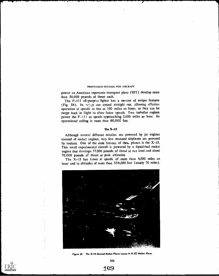
PROPULSION SYSTEMS FOR AIRCRAFT
power an American supersonic transport plane (SST) develop morethan 50,000 pounds of thrust each.
The F-111 all- purpcsc fighter has a number of unique features(Fig. 56). Its Aitgs can extend straight out, allowing effectiveoperation at speeds as low as 100 miles an hour; or they can beswept back in flight to allow faster speeds. Two turbofan enginespower the F-111 to speeds approaching 2,000 miles an how.. Itsoperational ceiling is more than 60,000 feet.
The X -15
Although several different missiles are powered by jet enginesinstead of rocket engines, very few manned airplanes are poweredby rockets. One of the most famous of then, planes is the X-15.This small experimental aircraft is powered by a liquid-fuel rocketengine that develops 57,000 pounds of thrust at sea level and about70,000 pounds of thrust at peak altitudes.
The X-15 has flown at speeds of more than 4,000 miles anhour and to altitudes of more than 354,000 feet (nearly 70 miles).
rite 4. '
Figure 57. The X-15 Manned Rocket Plane Leaves its B-52 Mather Plane.
102
109

PROJECTIONS
Pump
Cold Propellant
Fuel (uranturr)elements
Reoctor
Heated propellant
Nozzle
Figure 58. Nuclear Rocket may be Next Step in Rocket Propulsion.
Because of its design, the X-15 does not take off from the groundunder its own power. It is carried to high altitudes by a B-52 jetbomber and released, then performs under power from its rocketengine (Fig. 57).
Testing in the X -15 program, which ended in 1968, led to manydevelopments applied to use in jet aircraft and in space flight.
103

PROPULSION SYSTEMS FOR AIRCRAFT
ROCKETS
Great strides have been made in improving rocket propulsion,both in engine design and in the development of more powerfulpropellants. Chemical propellants with specific impulses in theneighborhood of 300 seconds are well developed.
But since the power available from chemical combustion (oxida-tion) seems limited. scientists are considering several other methodsof propulsion. Included on this list as a possible early developmentis the nuclear rocket (Fig. 58).
The nuclear rocket does not use any combustion process. Itdevelops hot exhaust gases for propulsion (as does the chemicalrocket). but it forms these gases by passing a fluid propellantthrough a fission reactor. The fission reactor produces heat bysplitting the atoms of certain materials, thereby releasing greatamounts of energy.
Liquid hydrogen is the propellant most mentioned for use in thenuclear engine. because of its light weight. The liquid hydrogenwould pass through the reactor. The intense heat would transformthe liquid into hot gases. and the gases would exhaust through thenozzle in the same manner as do the gases in the chemical rockets.
Another possible method of using the fission reactor in a rocketwould avoid the severe strains of the heat on the materials of thereactor's walls. This method would employ a gaseous fissile material,instead of the hot reactor walls. to heat the propellant gas. The fissilegas would be held in the center of the rocket by magnetic means.
This system is still under investigation, as are most of the pro-pulsion systems mentioned in this chapter. It has been estimated,though, that "conventional" nuclear rockets may provide specificimpulses up to 1,200 seconds.
Electrical Propulsion
Scientists are looking into the possible use of electrically poweredengines for rockets. The two electrical engines most commonlymentioned are ion and plasma propulsion rockets.
These electrical propulsion systems operate by thrusting electri-fied, or ionized, particles out of the rocket exhaust at very highvelocities. But the energy density of these particles is small. Forthis reason, electrical propulsion as now envisioned could not pro-vide enough thrust to get a missile off the ground.

PROJECTIONS
Once a space ship is put into free orbit, however, very smallamounts of thrust will increase the ship's flight velocity. A spaceship fitted with ion, plasma, solar, or photon propulsion equipmentwould have to be put into space by another means, probablychemical or nuclear propulsion. In free space, conventional powercould be turned off and small-thrust propulsion could take over.
Ionization
Both the ion and the plasma propulsion engines require largequantities of electricity for their operation. To understand how thesesystems work, we will review the physical makeup of molecules andatoms.
A molecule is the smallest particle of an element that retains allthe qualities of the element. These qualities are as they are becauseof the particular way the smaller elements of the molecule are ar-ranged.
Figure 59. The Atom Includes Neutrons and Protons, Orbited by Electrons.
There are as many different kinds of molecules as there are ele-ments. The only difference in the molecules is the number of smallerparticles, called atoms, they contain and the way these atoms aremade up.
So every molecule is composed of atoms. Every atom, in turn,is composed of smaller parts. These parts are the neutrons, pro-tons, and electrons. They are arranged in the atom to form a nu-cleus, or center part, and orbits, or rings around the nucleus.
Neutrons are particles which have no electrical charge. Protonsare particles with a positive electrical charge. Electrons are particleswith a negative electrical charge.
105
2I

PROPULSION SYSTEMS FOR AIRCRAFT
The nucleus is composed of a given number of neutrons and the
same number of protons. The orbits are rings where the electronsrotatc around the nucicus (Fig. 59). Evcry stable atom has thesame number of electrons in orbit as it has protons in the nucleus.This means positive and negative charges balance.
HEATED GRIDPROPELLANT
ACCELERATING GRID
TO POWER SUPPLYLARGE
VOLTAGE TO POWER SUPPLYDIFFERENCE
ION ROCKET ENGINE
TO ELECTRIC POWER SUPPLY
INJECTEDPROPELLANT
TO PROPELLANT TANK
POSITIVEELECTRODE
INJECTEDPROPELLANT
HEATING ARC
NEGATIVE ELECTRODE
NOZZLE
PLASMA JET
Figure 60. Examples of Ian and Plasma Rocket Engines.
106

PROJECTIONS
In the process of ionization, an outside force knocks free of orbitone or more of the circling electrons. This leaves the atom withmore protons than electrons, thus giving it a positive charge andmaking it unstable. Since the atom is charged, so is the molecule ofwhich it is a part.
Ion Rockets
The ion engine probably will use the metal cesium as a propel-lant. Each molecule of the cesium will be given an electrical charge;that is, the cesium will be ionized.
This ionization can be accomplished by passing the cesium overheated metal grills. The heat acts as the outside force and knockselectrons loose. The charged molecules (or ions) can then be ac-celerated through the nozzle to very high velocities by means of anelectrical magnetic field (Fig. 60).
The performance of such an ion engine is very good in thelaboratory. Specific impulses can be obtained up to 20,000 sec-onds. but very heavy electrical equipment is required to provideenough power for good ionization.
Plasma Rockets
Another electrical rocket, called the plasma rocket, would workmuch the same as the ion rocket. But the heat would be supplieddirectly to a gaseous propellant through a powerful electrical arcinstead of through a grill (Sec Fig. 60).
This method would provide high specific impulses, up in thethousands of seconds, without the heat problems involved in theion engine. The heated propellant in the plasma rocket would beionized as it passed through the electrical arc. The ionized gas, orplasma, as it is called, then could be directed out the exhaust nozzleat high velocities to produce thrust.
Plasma, in this sense, is a newly recognized fourth state ofmatter, taking its place along with the liquid, gaseous, and solidforms. Plasma is a wisp of gas that has been heated and compressed,so that it becomes electrically charged.
Future development of the ion and plasma rockets may includethe development of nuclear reactors as supplier of the large amountsof electricity required.
107

PROPULSION SYSTEMS FOR AIRCRAFT
LARGE METALLIZED REFLECTION BALLOON
Sun's rays
THRUST FORCE
INSTRUMENT PACKAGE
Figure 61. Solar Sail would be Pushed by Sun't Radiation.
Solar Propulsion
One proposed method of propulsion in outer space is to harnessthe radiation cncrgy of the sun. The cncrgy density of solar radia-tion is small as compared to the high density of chemical propel-lants; but solar radiation is sufficiently strong to move a space shipin "open" space. It is theorized that light rays have energy, and thatthis energy is made up of small bundles of power, called photons.
Two ways have been proposed as methods of harnessing sunlightfor space propulsion. One of the ways is the "solar sail," a largeballoon coated on one side with a metallic material (Fig. 61). Theballoon would be attached to the space ship. The constant stream ofpressure from the sun's radiation would push against the metallic sideof the balloon, just as wind pushes against a sail in a sailing ship.The pressure would move the space ship along.
Another method of using the sun's rays for propulsion would beto trap the rays and use them to heat a gas inside the space ship.The expanding gas would then be expelled through the exhaustnozzle, as in the chemical propulsion rocket.

PROJECTIONS
Photon Rockets
Some researchers have proposed that a space ship may be pro-pelled by internally-produced photons, the little bundles of energy
mentioned above. In the photon rocket, light or other radiationgenerated within the rocket could be emitted from the exhaust in afocused beam. The action-reaction principle would make the space
ship move.A certain amount of momentum can be found in light beams,
but so far, it is very small. A big military searchlight, for instance,may be considered as a version of the photon rocket. But such asearchlight yields less than one ten-thousandth of a pound of thrustfrom a power consumption of 100 kilowatts.
Unless a method could be found to completely convert matter into
energy, the photon rocket system would be very inefficient.
REVIEW QUESTIONS
1. What was the first operational jet fighter plane developed by the UnitedStates? When was news of the aircraft announced?
2. Name one unique feature of the F-111.3. Now would a nuclear rocket be similar to the rockets in use today?
4. Why would electrically-driven missiles he satisfactory in outer space, but notfor take-off from any planet?
S. Describe the operation of the ion rocket. The plasma rocket. The solarsail.
6. What are "photons"?
THINGS TO DO
1. Find out what kind of propulsion systems power the latest types of air-craftfor instance, the C-5, the proposed AMSA, and the developingV/STOL aircraft. Report on any significant powerplant developments used
on these aircraft.
2. Designate someone to investigate and report on the progress of NERVA(nuclear engine for rocket vehicle application). Include in your report someof the major problems with the engine, how long it will be before NERVAis used operationally, how long The engine has been in study and de-velopment. Also speculate on the implications of NERVA in areas other
than rocket flight.
109
1 .6

yf
PROPULSION SYSTEMS FOR AIRCRAFT
SUGGESTIONS FOR FURTHER READING
HAGGERTY. JAMES J. ed. United States Aircraft, Missiles, and Spacecraft.Washington, D.C.: National Aerospace Education Council, current.
House Document No. 86, 86th Congress, 1st Session. Space Handbook: Astro-nautics and its Applications. (Also published as Foundations of Air PowerII, Volume 4.) Washington, D.C.: U.S. Government Printing Office. 1958.
National Aeronautics and Space Administration. Structures for Space Opera-tions. Washington. D.C.: U.S. Government Printing Office.
SANGER, EUGEN. Space Flight: Countdown for the Future. New York: Mc-Graw-Hill Book Co., 1965.
BRAUN, WERNHER VON, and FREDERICK 1. ORDWAY 111. History of Rocketryand Space Travel. Chicago: J. G. Ferguson Publishing Co., 1966.
110

Summary
WE MAY SAFELY predict that for the foreseeable future,chemical propulsion will be the mainstay of rocketpower.
Nuclear engines probably will be developed soonto the point that they will be used more and more often.
Serious study and experimentation with ion andplasma rockets is very promising, and could lead topractical use of these engines before long. Electricaland solar propulsion may prove effective in poweringspace ships over very long distances in open space.But within the gravitational pull of a celestial body,they are not powerful enough to function alone.
A combination of rocket and jet engines may beused to get future space ships off the ground, and tobring back for re-use the big booster sections of thefirst and second stages.
PERSPECTIVE ON PROPULSION
As man prepares to begin what probably will be hisgreatest adventure, travel into space, perhaps we shouldtake a few seconds to get some perspective on thehistory of the engines which will power his ships. Toget into space, man first had to get off the ground; toget off the ground, and stay off it for any length oftime, he needed power. To see how long he workedto develop enough power to get off the ground, con-sider the following historic events. Note how, whileAmerica was engaged in winning its territory and itsfreedom, Europe was at work in the laboratory and inthe field.
1111_418

The origins of the first successful aircraft enginemust be found in the piston-moving steam engine,invented by James Watt of Scotland. Watt inventedhis engine in 1769, the same year Napoleon Bonapartewas born, and four years before the Boston Tea Party.Changes in the steam engine were made gradually. In1820, the Missouri Compromise Act passed the U.S.Congress and W. Cecil reported the development ofan internal combustion engine in England. In 1860,Abraham Lincoln was elected President of the UnitedStates, and J. J. E. Lenoir of France designed the firstpractical internal combustion engine. Germany's Nik-olaus Otto came up with a coal gas-burning engine in1876, the same year U.S. Gen. George Custer and histroops were wiped out by Indians on the Little BigHorn and Wild Bill Hickok was shot down from behindwhile playing poker. Gottlieb Daimler, another Ger-man, invented a high-speed gasoline engine in 1883,three years before the Apache Indian Geronimo sur-rendered to th U.S. Army. Finally in 1903, theWright brothers combined aerodynamics with an en-gine of sufficient power to get their "Flyer" off theground. That was a year before the subway systemopened in New York City.
Perhaps these historical parallels will demonstratehow long the search for powerful engines has beengoing on, and how recently it resulted in success. Thelateness of this success will give you some idea of howrapidly the engine has been developed to its presentstate. No one can say what may be just around thecorner, but one thing is sure: man has learned to takeflight for granted: he has even had a taste of space,and has found it to his liking. He will not stop lookingfor better ways to power his flying machines. For thisreason, research into propulsion systems for aircraftwill continueand it will turn up some startlingresults.
112
1:99

Glossary
A
accelerating systemcarburetor device designed to prevent "lean" mixturesduring sudden openings of the throttle.
accelerationthe action or process of velocity increase, or the rate of thatincrease.
aerodynamicsthat field of dynamics concerned with the motion of air andother gaseous fluids, or of the forces acting on bodies in motionrelative to such fluids.
afterburneran auxiliary combustion chamber within the tailpipe section ofsome jet engines.
air bafflewall designed to direct cooling air through engine parts.airfoila surface or body, such as a wing or propeller, especially designed to
obtain reaction, such as lift or thrust, from the air through which itmoves.
airframethe structural components of an airplane. including the frameworkand skin of the fuselage. empennage, wings, landing gear, and enginemounts.
augmenter tubea venturi tube located behind some reciprocating engines.which increases airflow through the engine by creating a suction effect,aiding in engine cr,ling.
axial flowin a jet aircraft, the flow of air along the longitudinal axis ofthe engine.
B
ballcona nonrigid airship without a propelling system.banka series of cylinders arranged in a circular row in a radial engine;
also, in a different reference, to incline an airplane laterally.Bernoulli's lawa law of physics stating that as the velocity of a fluid in-
creases, its internal pressure decreases.
C
cama part mounted on a shaft and used to impart a reciprocating or alter-nating motion to another part by bearing against it as it rotates.
camshaftthe shaft on which the cams, or cam rings. are mounted.carburetora device for mixing fuel and air in the proper proportions to
form a combustible mixture and for conveying this mixture to the in-take manifold, and ultimately, to the cylinders of an engine.
carburetor icing icing formed in the carburetor as a result of rpid vaporiza-tion and cooling.
centrifugal flowin a jet aircraft, the movement of air away from thecenter of rotation of the compressor.
compressor a machine or apparatus for compressing air for delivery to thecombustion chamber of an engine.
113

GLOSSARY
condensera device for storing electrical energy.connecting roda rod connecting the piston to the crankshaft of an enginesystem.cowlinga covering over an aircraft section for directing and regulatingthe flow of cooling air. for streamlining, or for protection of the section.crankcasethe section encasing the crankshaft of an engine.crankshaftthe shaft of an internal combustion reciprocating engine by whichreciprocating motion is changed into rotational motion.cylinderthe combustion chamber in a reciprocating engine.
D
detonationthe instantaneous and abnormal combustion of an unburnedpart of fuel mixture in the cylinder of an engine.dieselan internal combustion engine in which air is compressed to a tem-perature sufficiently high to ignite fuel injected into the cylinder, wherecombustion actuates a piston.dirigiblea lighter-than-air aircraft with its own motive power, which maybe steered in any desired direction by its crew.distributoran apparatus for directing the secondary current from the induc-tion coil to the various spark plugs of an engine in their proper firingorder.
economizera system associated with the carburetor that meters the fuelflow to economize on fuel at low speeds.engine systems the different sections of an engine that, working together.comprise the engine as a whole. These include the mechanicA c.s.ol-ing, electrical. lubrication, fuel, carburetor, and propeller systems ofa reciprocating engine and the compressor, combustion, turbine. andexhaust systems of a jet engine.escape velocity in space flight, the speed at which an object is able to over-come the gravitational pull of the earth or other celestial bodies.external combustion enginea fuel-consuming engine in which fuel combustiontakes place outside the cylinders or outside the reaction chamber.
Ffeathering -- changing the blade angle of a contrAlable-pitch propellr r so thatthe propeller blade chords are parallel or almost parallel to the line offlight.fissionof radioactive material splitting apart within the atomic nucleus.forcein physics, an influence that if applied to a free body. restilts chieflyin an acceleration of that body.four-cycle enginean internal combustion, piston engine requiring fourstrokes of each piston to complete the cycle of intake, compression,combustion, and exhaust.feel injectionthe forced spraying of fuel and air under pressure into theintake passages of an aircraft engine or into a combustion chamber.fusionof radioactive material: the act of process of fusing or uniting theatomic nuclei of an isotope to form other nuclei under the influence ofintense heat.

C.
GLOSSARY
Hhorsepowera unit of power in the United States equal to 746 watts and
nearly equal to the English gravitational measure of 550 foot-pounds/minute.
hypergolic fuela rocket propellant that ignites spontaneously upon contactwith an oxidizer.hypersonicof or pertaining to the speed of objects moving at mach 5 or
greater.
inline enginean internal combustion, reciprocating engine in which thecylinders are arranged in one or more straight rows, as distinguished fromthe radial engine.
intake manifolda pipe which leads the fuel mixture from the carburetorto the cylinder or cylinders of an engine.
internal combustion engineany engine in which the pressure of gases formedby combustion of fuel is directly used to give the engine motion; usuallyrefers to piston-driven engines.
ionan atom or group of atoms that carries a positive or negative electricalcharge as a result of having lost or gained one or more electrons.
ionizationconversion of a substance (as air or liquid) into ions.
J
jet enginea species of reaction engine, namely, an engine that takes in airfrom outside for use as a fuel oxidizer and projects a jet of hot giv3e4backward to create thrust, the gases being derived from combustion withinthe engine.
Kknocka sharp, metallic noise in a reciprocating engine, caused by abnormalignition.
L
lean mixturea fuel-air mixture containing a low percentage of fuel and ahigh percentage of air, as compared to a normal or rich mixture.
Mmacha unit of speed measurement for a moving object equal to the speedof sound in the medium in which the object moves.magnetoa generator using permanent magnets to generate an electric
current, especially for the ignition of an internal combustion engine.massa measure of the quantity of matter in a body, as distinguished fromits weight.
0octane ratinga number assigned to a liquid fuel to designate its relativeantiknock value in a reciprocating engine.
115

GLOSSARY
oxidizerin a rocket propellant, a substance that furnishes the oxygen forburning the fuel.
ppayloadthat part of the load carried in a rocket vehicle, aircraft, or other
vehicle so as to obtain the results for which the vehicle is launched or
driven.photon enginea projected reaction engine in which thrust would be obtained
from a stream of light rays.pistona sliding piece moved by or moving against fluid pressure that
usually consists of a short cylinder fitting within a cylindrical vessel,along which it moves back and forth.
plasmaan electrically conductive mixture of positive ions, electrons, andneutral particles, differing from ordinary gas in its electrical conductivity,
in its behavior as affected by a magnetic field, and in its internallystored energy.
propellanta fuel, Other liquid or solid, for powering a rocket engine; con-tains both fuel id oxidizer.
propellera device that consists of a central hub with radiating blades placedand twisted so that each forms part of a spiral plane, and used to propelor pull an aircraft forward through the air by the action of the blades eat-ing into the air and thrusting it rearward.
pulsejeta kind of jet engine having neither compressor nor turbine, butequipped with vanes in the front end which open and shut, taking inair to create power in rapid periodic bursts rather than continuously.
R
radial enginean aircraft engine with one or more stationary rows of cyl-inders arranged radially around a common crankshaft.
ramjeta kind of jet engine consisting essentially of tube open at both endsin which fuel is burned continuously to create a jet thrust, and havingneither compressor nor turbine, the air for oxidizing the fuel beingrammed into the engine as the engine moves forward.
reaction enginean engine that derives thrust by expelling its gases of com-bustion to the rear.
reciprocating enginean engine in which power is delivered by a back-and-forth movement of a piston or pistons; specifically, a piston-driven in-ternal combustion engine.
regenerative coolingthe cooling of a rocket engine by circulating the fuelor oxidizer fluid in coils about the engine prior to use in the combustionchamber.
rich mixturea fuel-air mixture containing a high percentage of fuel and alow percentage of air, as compared with a normal or lean mixture.
rocket enginean engine or motor that moves forward by ejecting a streamof hot gases to the rear, and which, carrying its own oxidizer, is inde-pendent of the atmosphere for its operation.
rotora rotating part of an electrical or mechanical device or piece ofequipment, as in the compressor of a jet engine.
RPMrevolutions per minute, applicable to any rotating mechanism. In areciprocating engine, usually refers to crankshaft revolutions.
116
1 3

GLOSSARY
$
self-inductioninduction within an electrical circuit induced by the circuititself. Induction, or inductance, is the force in electricity that correspondsto inertia in matter.
shrinkingin engine construction, a method of securing the cylinder head tothe cylinder barrel by heating the head, screwing it onto the barrel, andallowing it to set into place as it cools.
specific impulsea performance measurement of a rocket propellant, ex-pressed in seconds, and equal to the thrust in pounds divided by theweight flow rate in pounds per second.
stagein a rocket vehicle powered by successive units, one of the separatepropulsion units; a section of the vehicle housing a rocket engine ormotor.
statorin machinery, a part that remains fixed in relation to a rotating part,such as the stator section of a compressor.
superchargera pump or compressor for forcing more air or fuel-air mixtureinto a reciprocating engine than would normally induct at the prevailingatmospheric pressure.
supersonicof or pertaining to the speed of an object moving at a speedgreater than mach 1, or at a speed between mach I and mach 5.
T
throwthe eccentric bend in a crankshaft, onto which is joined the connectingrod.
thrustthe driving force exerted on any aircraft, rocket, or other object byits rotating propeller or rotor blades, jet or rocket engines, or otherpropulsive device; a unit for measuring the power of a reaction engine.
thrust horsepowerthe thrust of a jet engine or rocket expressed in terms ofhorsepower.
thrust reversera device for redirecting a reaction engine's exhaust to anopposite direction.
turbinea mechanical device or engine that spins in reaction to a fluid flowthat passes through or over it.
turbofana turbojet engine with part of the compressor outside the innerengine case.
turbojeta jet engine with a turbine-driven air compressor.turboprop--a gas turbine engine designed to drive a propeller from a turbine
shaft.
V
valveany device, such as a swiveling plate, hinged lid, plug, or ball, throughwhich the flow of gas, liquid or certain solid materials may be checked,stopped, started, or regulated.
vapor locka stoppage or diminution in the fuel flow of an engine causedby fuel vapor accumulating in the fuel lines.
venturi tubea short tube with a constricted throat which, when placed in afluid flow parallel to the flow, brings about an increase in flow velocityat the throat with a consequent diminished pressure within the fluid atthe throat, in accordance with Bernoulli's Law.
117

GLOSSARY
viscosityin a liquid, such as oil, the property of internal resistance, causedby molecular attraction, that makes the liquid resist flow.
windmillof a propeller: to rotate by the force of air acting upon it, withoutpower from the engine.
wind tunnela chamber through which air is forced at controlled velocities,up to several thousand miles an hour, and in which airfoils, airplanes,missiles, scale models of airplanes, or other objects are mounted in orderto observe and study the airflow about such objects, as well as theaerodynamic effects upon them.
118
I .5

INDEXA
Afterburner: 80-81, 84Air, nature of: 3Aircraft: 2, 6-8, 81-85, 99-100, 102-104,
112Aerodrome: 6A-7: 84Boeing 707: 82, 84Boeing 720:.82Boeing 727: 848-52: 82, 84, 103Convair 580: 83C-130: 83C-133: 83C-141: 84Douglas DC-8: 82Douglas DC-9: 84First jet: 8Flyer: 2,6, 7, 112F-4: 84, 100F-5: 81F-105: 81F-111: 102KC-135: 84Lockheed Electra: 83P-80: 8, 99-100SR-71: 82SST: 85, 102YF-12A: 100X-15: 102-103XB-70: 100
Aviation: 13Commercial: 13General: 13Military: 13
B
Balloons: 4Bernoulli's Principle (Bernoulli's Law): 24,
37, 39, 57Borelli, G. A.: 3-4
Bypass engine: SEE Turbofan
C
Caley, George: 6Camshaft: 16-17Carburetor: 18, 29, 31, 33-47, 53
Accessories: 40-43, 45Diaphragm: 46Float: 37-40, 43Pressure injection: 44-45
Combustion: 2, 4, 16, 33, 47, 69-74, 76-78,82-84, 88, 90, 92
Chamber: 16, 47, 69-74, 76-78, 82-84,88, 90, 92
External: 2, 4Internal: 4Spontaneous: 33
Compressor: 8, 72-77, 79, 82-84Axial flow: 73-76Centrifugal flow: 73-75Split: 76-77
Condenser: 50Cooling: 20-25, 55, 77-78, 92
Air: 20, 23-24, 77-78Liquid: 20-21, 24-25, 55Regenerative: 92SEE ALSO, Heat
Cowling: 23Crankcase: 20, 54-55Crankshaft: 16-17, 20-23, 26, 48, 53,
57-58, 61-62Cylinder: 15-25, 32-33, 36-37, 39-40, 42,
47, 51-52, 54-55, 73
D
Daimler, Gottlieb: 5, 112Da Vinci, Leonardo: 3DeRochas, Alphonse Beau: 5Dirigible: 5Distributor: 50-51
Ducted air engine: SEE Turbofan
E
Electrical rocket: SEE Rocket engine typeElectricity: 47-53, 104-105, 107Engine: 2, 4-10, 13-56, 62-96, 111-112
Diesel: 18-19Fourcycle: 5Inline: 20-21, 55Internal combustion: 2, 4-6, 112Jet: 7-10, 47, 65-89, 111Radial: 21-22, 55Reaction: 7-10, 63, 65-96Reciprocating: 8-10, 13-56, 62-63,
65-67, 69, 72, 82-83, 88-89Rocket: 9, 70, 89-96, 111
Engine sections, jet: 66, 68, 71-81, 83,87-88
Accessory: 87Combustion: 66, 72, 77-78Compression: 66, 72-77, 87Exhaust: 66, 72, 79-81, 83, 88Intake: 66, 68, 71-72, 87Turbine: 78-79, 83
119

INDEX
Engine sections, Rocket: 90-92Exhaust: 91-92Fuel: 90, 92Thrust chamber: 90-92
Engine systems, reciprocating: 15-18, 22-25, 29, 33-63
Cooling: 22-25, 29, 55Fuel: 29, 33-47, 53Ignition: 29, 47-53Lubrication: 29, 53-56Mechanical: 15-18, 29, 53Propeller: 29, 56-63
Escape velocity: 94-95
F
Forces, aerodynamic and physical: 56-57,59-62, 67, 69, 74, 79-80
Centrifugal force: 59-60, 74, 79Drag: 61Lift: 56-57, 59-60Thrust: 57, 59-60, 62, 67, 69, 80Torque: 62Torsion: 59-60
Fourstroke cycle: 5, 15-17, 21, 39-40,66-67
Fuel: 17-18, 22, 30-33, 35-40, 42Diesel: 18Gasoline: 17, 22, 31, 33, 35-36, 39-40,
42Kerosene: 77Knock: 32-33, 36-37Octane rating: 31-33Volatility: 30-31SEE ALSO, Propellant
Gifford, Henri: 4Gliders: 5-6Goddard, Robert: 8
G
H
Haenlein, Paul: 5Heat: 22, 25, 37, 54, 78-80, 88, 107-108
Injection: 47, 78, 81, 88, 92Fuel: 47, 78, 81, 92Water: 88
Ionization: 105-107Ion rocket: SEE Rocket engine types
J
Jet engine types: 68-85, 87-89, 100,Pulsejet: 70-72
102
Ramjet: 68-70, 80Scramjet: 70Turbofan: 83-85, 87, 102Turbojet: 72-85, 87-89, 100Turboprop: 82-84
L
Langley, Samuel: 6Lilienthal, Otto: 6Liquid rocket: SEE Rocket engine types
M
Magneto: 47-49, 52-53, 87Manifold, intake: 37, 39-40, 42-43, 47, 61Manley, Charles: 6-7Materials: 4, 25-26, 88, 92Missiles: 70, 72, 82, 89, 91, 93, 95
Atlas: 93Bomarc: 70Delta: 93Honest John: 91Hound Dog: 82Little John: 91Minuteman: 91Polaris: 91Poseidon: 91Redhead/Roadrunner: 70Saturn: 93Titan: 93Titan 95V-1: 72, 89
Mixed rocket: SEE Rocket engine typesMoss, Sanford: 7-8Motion, Laws of: 7, 9, 57, 67, 89Multistage rocket: SEE Rocket engine types
N
Newton, Isaac: 7Noise suppressor: 85-87Nuclear Rocket: SEE Rocket engine types
0Oberth, Herman: 8Ohain, Pabst Von: 8Oil: 18, 54-56, 87
Diesel: 18Properties of: 54-55System: 55-56, 87
Otto, Nikolaus: 5, 112
P
Parachute brake: 85Photon rocket: SEE Rocket engine typesPiston: 13, 15-18, 22, 26, 32, 39, 52-54
120

INDEX
Plasma rocket: SEE Rocket engine typesPower terms: 8-10, 20-22, 62, 93, 95, 104,
107, 109Horsepower: 8-10, 20-21, 62Specific impulse: 93, 95, 104, 107Thrust: 9-10, 22, 109Thrust horsepower: 10, 62Torque horsepower: 62
Propellant: 89-94, 104, 107-108, II IChemical: 90-93, 104, 108Electrical: 107, II 1Grain: 90Hypergolic: 92-93Liquid: 90, 92-94Nuclear: 104, 107, 1 1 IPower, rating oft 93
Propeller: 13, 16-18, 22, 53, 56-63, 65,67, 76, 82-85
Efficiency: 57, 62-63, 83Feathering: 61Nomenclature: 57-.!.Pitch: 60-61
Propjet: SEE Jet engine typesPulsejet: SEE Jet engine types
R
Ramjet: SEE Jet engine typesRocket engine types: 90-95, 104-109, 1 1 1
Electrical: 104-105Ion: 105, 107, 111liquid: 92-94Mixed: 91, 95Multistage: 95Nuclear: 104, 107, 1 1 1Photon: 105, 109Plasma: 105, 107, II 1Solar: 105, 108, 111Solid: 90-92
Rocketry: 8, 89-96
S
SantosDumont, Alberto: 5Schwartz, David: 5Scramjet: SEE Jet engine typesSolar rocket: SEE Rocket engine typesSolid rocket: SEE Rocket engine typesSpark plug: 17, 32, 47, 49-52, 68-69, 78Starting system: 52-53, 87
Taylor, Charles: 7Thrust: SEE Forces, aerodynamic and phys-
icalThrust reversers: 85-87Tsiolkovsky, Konstantin: 8Turbofan: SEE Jet engine typesTurbojet: SEE Jet engine typesTurboprop: SEE Jet engine typesTurbine, gas: 7, 43, 72-73, 76, 78-79,
82-83, 92
V
Valve: 15-17, 22, 25, 32, 39-40, 47Venturi: 37-38, 43-46
wWatt, James: 8, 112Whittle, Frank: 8Wright Brothers: 2-3, 6-7, 112
zZeppelin, Ferdinand Von: 5
121
* U.B. OOVERNM NTINO OFFICE: 1972-.141-046/750E-REGION 4