Doc N° - Alpha Magnetic Spectrometer · 2.2 reference documents ... (ssp 52000-idd-erp chap...
68
Transcript of Doc N° - Alpha Magnetic Spectrometer · 2.2 reference documents ... (ssp 52000-idd-erp chap...


Doc N°: ACP-RP-CGS-003
ACOP Issue: 1 Date: Jan. 2005
ACOP DESIGN REPORT Page 2 of 68
CHANGE RECORD
ISSUE DATE CHANGE AUTHORITY REASON FOR CHANGE AND AFFECTED SECTIONS
1 January 2005 - First Issue

Doc N°: ACP-RP-CGS-003
ACOP Issue: 1 Date: Jan. 2005
ACOP DESIGN REPORT Page 3 of 68
LIST OF VALID PAGES
PAGE ISSUE PAGE ISSUE PAGE ISSUE PAGE ISSUE PAGE ISSUE
1 - 68 1

Doc N°: ACP-RP-CGS-003
ACOP Issue: 1 Date: Jan. 2005
ACOP DESIGN REPORT Page 4 of 68
TABLE OF CONTENT
1. SCOPE AND INTRODUCTION................................................................................................................. 9
2. DOCUMENTS....................................................................................................................................... 10 2.1 APPLICABLE DOCUMENTS............................................................................................................... 10 2.2 REFERENCE DOCUMENTS............................................................................................................... 11
3. DEFINITIONS AND ACRONYMS............................................................................................................ 12
4. DESCRIPTION OF ACOP...................................................................................................................... 16 4.1 FUNCTION AND PURPOSE OF ACOP................................................................................................ 16 4.2 UTILIZATION CONCEPT..................................................................................................................... 17
5. ELECTRICAL DESIGN .......................................................................................................................... 18 5.1 ISS AVIONICS ARCHITECTURE ......................................................................................................... 18 5.2 ACOP AVIONICS ARCHITECTURE ..................................................................................................... 19
5.2.1 POWER DISTRIBUTION AND POWER FEEDERS PROTECTIONS................................................. 20 5.3 AVIONICS DESIGN DETAILS ............................................................................................................. 21
5.3.1 ACOP-SBC ................................................................................................................................ 23 5.3.2 ACOP-T101................................................................................................................................ 25 5.3.3 ACOP-T102................................................................................................................................ 26 5.3.4 ACOP-T103................................................................................................................................ 27 5.3.5 ACOP-BP................................................................................................................................... 28 5.3.6 ACOP-PS................................................................................................................................... 30 5.3.7 LCD MONITOR (TBC) .................................................................................................................. 31 5.3.8 HARD DRIVES ........................................................................................................................... 31 5.3.9 THERMAL SENSORS NETWORK................................................................................................ 31 5.3.10 INTERNAL HARNESS ................................................................................................................. 32
5.4 AVIONICS INTERFACES.................................................................................................................... 33 5.4.1 POWER INTERFACES................................................................................................................ 33 5.4.2 DATA AND COMMANDS INTERFACES........................................................................................ 33
5.5 CREW INTERFACES......................................................................................................................... 33 5.6 POWER BUDGET ............................................................................................................................. 34
5.6.1 OPERATIVE CASE – POWERED DOWN..................................................................................... 34 5.6.2 OPERATIVE CASE – COLD START............................................................................................. 35 5.6.3 OPERATIVE CASE – WARM START ........................................................................................... 35 5.6.4 OPERATIVE CASE – ACTIVE IDLE.............................................................................................. 36 5.6.5 OPERATIVE CASE – ACTIVE RECORD....................................................................................... 36 5.6.6 OPERATIVE CASE – ACTIVE PLAYBACK ................................................................................... 37 5.6.7 OPERATIVE CASE – ACTIVE RECORD AND PLAYBACK............................................................. 37
6. EMC REQUIREMENTS ASSESMENT AND VERIFICATION APPROACH .................................................. 38 6.1.1 EMC APPLICABLE DOCUMENTS................................................................................................ 38
6.1.1.1 EMC VERIFICATION ............................................................................................................ 38 6.1.2 EMC REQUIREMENTS ............................................................................................................... 38
6.1.2.1 CE 01 CONDUCTED EMISSION REQUIREMENT ................................................................... 38 6.1.2.1.1 CE 01 VERIFICATION ....................................................................................................... 38
6.1.2.2 CE 03 CONDUCTED EMISSIONS.......................................................................................... 38 6.1.2.2.1 CE 03 REQUIREMENTS.................................................................................................... 38 6.1.2.2.2 CE 03 VERIFICATION ....................................................................................................... 38
6.1.2.3 CE 07 CONDUCTED EMISSIONS.......................................................................................... 39 6.1.2.3.1 CE 07 REQUIREMENTS.................................................................................................... 39 6.1.2.3.2 CE 07 VERIFICATION ....................................................................................................... 39
6.1.2.4 CS01 CONDUCTED SUSCEPTIBILITY ................................................................................... 39 6.1.2.4.1 CS 01 REQUIREMENT (30 HZ – 50 KHZ)............................................................................ 39

Doc N°: ACP-RP-CGS-003
ACOP Issue: 1 Date: Jan. 2005
ACOP DESIGN REPORT Page 5 of 68
6.1.2.4.2 CS 01 VERIFICATION ....................................................................................................... 39
6.1.2.5 CS 02 CONDUCTED SUSCEPTIBILITY .................................................................................. 39 6.1.2.5.1 CS 02 REQUIREMENT (50 KHZ – 50 MHZ) ......................................................................... 39 6.1.2.5.2 CS02 VERIFICATION ........................................................................................................ 39
6.1.2.6 CS 06 CONDUCTED SUSCEPTIBILITY .................................................................................. 40 6.1.2.6.1 CS 06 REQUIREMENT...................................................................................................... 40 6.1.2.6.2 CS 06 VERIFICATION ....................................................................................................... 40
6.1.2.7 RE 02 RADIATED EMISSIONS.............................................................................................. 40 6.1.2.7.1 RE 02 REQUIREMENT...................................................................................................... 40 6.1.2.7.2 RE 02 VERIFICATION ....................................................................................................... 40
6.1.2.8 RS 02 RADIATED SUSCEPTIBILITY ...................................................................................... 40 6.1.2.8.1 RS 02 REQUIREMENT...................................................................................................... 40 6.1.2.8.2 RS 02 VERIFICATION ....................................................................................................... 40
6.1.2.9 RS 03 RADIATED SUSCEPTIBILITY ...................................................................................... 41 6.1.2.9.1 RS 03 REQUIREMENTS.................................................................................................... 41 6.1.2.9.2 RS 03 VERIFICATION ....................................................................................................... 41
6.1.3 ADDITIONAL REQUIREMENTS.................................................................................................... 41 6.1.3.1 CORONA EFFECTS ............................................................................................................. 41
6.1.3.1.1 CORONA REQUIREMENT................................................................................................. 41 6.1.3.1.2 CORONA VERIFICATION .................................................................................................. 41
6.1.3.2 STATIC ELECTRICITY .......................................................................................................... 41 6.1.3.2.1 ELECTROSTATIC DISCHARGE REQUIREMENT................................................................. 41 6.1.3.2.2 ESD VERIFICATION.......................................................................................................... 41
6.1.3.3 LIGHTNING.......................................................................................................................... 42 6.1.3.3.1 LIGHTNING REQUIREMENT.............................................................................................. 42 6.1.3.3.2 LIGHTNING VERIFICATION................................................................................................ 42
6.1.3.4 MAGNETIC FIELDS.............................................................................................................. 42 6.1.3.4.1 MAGNETIC FIELDS FOR EXPRESS RACK PAYLOADS IN THE ISS REQUIREMENTS ......... 42 6.1.3.4.2 MAGNETIC FIELDS FOR EXPRESS RACK PAYLOADS IN THE ISS VERFICATION.............. 42
6.1.4 GROUNDING & BONDING........................................................................................................... 42 6.1.4.1 GROUNDING & BONDING REQUIREMENTS ......................................................................... 42 6.1.4.2 GROUNDING & BONDING VERIFICATION............................................................................. 42
7. EMC ANALYSIS ................................................................................................................................... 43 7.1 GROUNDING / BONDING / ISOLATION............................................................................................... 43 7.2 IN – RUSH CURRENT........................................................................................................................ 43 7.3 CONDUCTED AND RADIATED EMISSION SOURCES.......................................................................... 44
8. GROUNDING PHILOSOPHY ................................................................................................................. 45
9. SOFTWARE......................................................................................................................................... 47 9.1 SCOPE OF THE SOFTWARE ............................................................................................................ 47
9.1.1 ACOP-SYS-SW.......................................................................................................................... 47 9.1.2 ACOP-ERL-SW .......................................................................................................................... 47 9.1.3 ACOP-APP-SW.......................................................................................................................... 47
9.2 ACOP-SYS-SW – OPERATING SYSTEM LEVEL SUPPORT................................................................ 48 9.2.1 BOOTROM MONITOR................................................................................................................. 48 9.2.2 LINUX OPERATING SYSTEM KERNEL ........................................................................................ 49 9.2.3 LINUX HRDL DEVICE DRIVER..................................................................................................... 50 9.2.4 LINUX HARD DRIVE DEVICE DRIVER.......................................................................................... 50 9.2.5 LINUX USB HOST DEVICE DRIVER............................................................................................. 50 9.2.6 LINUX VIDEO DEVICE DRIVER.................................................................................................... 50 9.2.7 BUSYBOX - COMMAND INTERFACE........................................................................................... 50
9.2.7.1 BUSYBOX FEATURES......................................................................................................... 50 9.3 ACOP-APP-SW - APPLICATION SOFTWARE PLATFORM................................................................... 51
9.3.1 COOPERATIVE MULTITASKING SYSTEM ................................................................................... 51

Doc N°: ACP-RP-CGS-003
ACOP Issue: 1 Date: Jan. 2005
ACOP DESIGN REPORT Page 6 of 68
9.3.2 TASKRIC.................................................................................................................................... 51 9.3.3 TASKRECORD ........................................................................................................................... 51 9.3.4 TASKMCT.................................................................................................................................. 52 9.3.5 TASKTQM.................................................................................................................................. 52 9.3.6 TASKXFER................................................................................................................................. 52 9.3.7 TASKWDT.................................................................................................................................. 52 9.3.8 TASKFEP .................................................................................................................................. 52
9.4 SOFTWARE DEVELOPMENT ENVIRONMENT.................................................................................... 52 10. MECHANICAL DESIGN......................................................................................................................... 53
10.1 REQUIREMENTS AND CONSTRAINTS............................................................................................ 53 10.1.1 LOCATION ? SSP52000-IDD-ERP P3-5~P3-11? .......................................................................... 53 10.1.2 DIMENSION (SSP52000-IDD-ERP P3-18) ..................................................................................... 53 10.1.3 PAYLOAD ZERO-G REQUIREMENT ? SSP52000-IDD-ERP P3-14)................................................ 53 10.1.4 MAIN ELECTRICAL PARTS ......................................................................................................... 53 10.1.5 ACCESSIBILITY TO HARD DRIVES FOR REPLACEMENT ............................................................ 54 10.1.6 MAIN FRONT PANEL REQUIREMENT ......................................................................................... 54 10.1.7 FIXED FRONT PANEL REQUIREMENT ........................................................................................ 54 10.1.8 STRUCTURAL LOAD FACTORS AND ANALYSIS (SSP 52000-IDD-ERP SSP52005-IDD-ER) ............ 54 10.1.9 STRUCTURAL SAFETY FACTOR (SSP 52000-IDD-ERP CHAP 4)................................................... 54 10.1.10 STRUCTURAL FIRST NATURAL FREQUENCE (SSP 52000-IDD-ERP CHAP 4) ............................ 54 10.1.11 THERMAL DESIGN AND LIMIT (SSP 52000-IDD-ERP CHAP 5) ................................................... 54
10.2 MECHANICAL ARCHITECTURE ...................................................................................................... 55 10.2.1 MECHANICAL STRUCTURE ........................................................................................................ 55 10.2.2 ELECTRICAL COMPONENTS LAY OUT........................................................................................ 56 10.2.3 LAY OUT OF CONNECTORS AND LCD (ON FRONT PANEL - TBC) ............................................... 57 10.2.4 THERMAL DESIGN..................................................................................................................... 57 10.2.5 ASSEMBLY PROCESS .............................................................................................................. 58
10.2.5.1 ASSEMBLY STEP 1 ............................................................................................................ 59 10.2.5.2 ASSEMBLY STEP 2 ............................................................................................................ 60 10.2.5.3 ASSEMBLY STEP 3 ............................................................................................................ 61 10.2.5.4 ASSEMBLY COMPLETE ...................................................................................................... 61
10.2.6 CARD LOCK............................................................................................................................... 62 10.2.7 HARD DRIVE INSTALLATION....................................................................................................... 62 10.2.8 CABLE HARNESS ...................................................................................................................... 63
10.3 MECHANICAL DESIGN .................................................................................................................. 64 10.3.1 MATERIALS ............................................................................................................................... 64 10.3.2 MACHINING AND ASSEMBLY..................................................................................................... 64 10.3.3 SURFACE TREATMENT.............................................................................................................. 64
10.4 MECHANICAL INTERFACES .......................................................................................................... 64 10.4.1 STRUCTURE MOUNTED INTERFACE .......................................................................................... 64 10.4.2 AIRFLOW INTERFACE................................................................................................................ 65
10.5 CREW INTERFACES ..................................................................................................................... 65 10.5.1 ACOP INSTALLATION................................................................................................................. 65 10.5.2 OPENING FRONT PANEL........................................................................................................... 65 10.5.3 REPLACING HARD DRIVES........................................................................................................ 65 10.5.4 TOOLS....................................................................................................................................... 65
10.6 MASS BUDGETS........................................................................................................................... 66 11. CREW TRAINING SYSTEMS................................................................................................................. 67
11.1 APPLICABLE DOCUMENTS ........................................................................................................... 67 11.2 MAJOR REQUIREMENTS FROM SSP57066 (SPIA)......................................................................... 67 11.3 MAJOR REQUIREMENTS FROM SSP58026-01 ............................................................................... 67

Doc N°: ACP-RP-CGS-003
ACOP Issue: 1 Date: Jan. 2005
ACOP DESIGN REPORT Page 7 of 68
LIST OF TABLES Table 2-1 Applicable Documents....................................................................................................................... 10 Table 2-2 Reference Documents ....................................................................................................................... 11 Table 5-1 ACOP Internal Harness ..................................................................................................................... 32 Table 5-2 Power Budget ................................................................................................................................... 34 Table 5-3 Operative Case – Powered Down........................................................................................................ 34 Table 5-4 Operative Case – Cold Start ............................................................................................................... 35 Table 5-5 Operative Case – Warm Start............................................................................................................. 35 Table 5-6 Operative Case – Active Idle............................................................................................................... 36 Table 5-7 Operative Case – Active Record ......................................................................................................... 36 Table 5-8 Operative Case – Active Playback ...................................................................................................... 37 Table 5-9 Operative Case – Active Record and Playback..................................................................................... 37 Table 8-1 Power Connector Pin Function ........................................................................................................... 45 Table 10-1 Main Mechanical Parts .................................................................................................................... 55 Table 10-2 ACOP Mass Budget ........................................................................................................................ 66 Table 10-3 Soft Bag Mass Budget..................................................................................................................... 66 Table 11-1 Applicable Training Documents......................................................................................................... 67

Doc N°: ACP-RP-CGS-003
ACOP Issue: 1 Date: Jan. 2005
ACOP DESIGN REPORT Page 8 of 68
LIST OF FIGURES Figure 5-1 AMS-02 Avionics Architecture........................................................................................................... 18 Figure 5-2 ACOP Electrical Block Diagram........................................................................................................ 19 Figure 5-3 ACOP Power Distribution Diagram .................................................................................................... 20 Figure 5-4 ACOP Main Components ................................................................................................................. 21 Figure 5-5 IEEE 1101.2 - Mechanical Core Specification for Conduction Cooled Eurocards .................................... 22 Figure 5-6 ACOP-SBC Functional Block Diagram.............................................................................................. 23 Figure 5-7 ACOP-T101 Functional Block Diagram .............................................................................................. 25 Figure 5-8 ACOP-T102 Functional Block Diagram .............................................................................................. 26 Figure 5-9 ACOP-T103 Functional Block Diagram ............................................................................................. 27 Figure 5-10 ACOP-BP Functional Block Diagram ............................................................................................... 28 Figure 5-11 ACOP-PS Functional Block Diagram ............................................................................................... 30 Figure 8-1 ACOP Grounding Philosophy ............................................................................................................ 46 Figure 9-1 Application Software Organization ..................................................................................................... 51 Figure 10-1 Location and configuration of ACOP................................................................................................. 53 Figure 10-2 Mechanical Main parts of ACOP...................................................................................................... 56 Figure 10-3 Electric Main parts of ACOP ........................................................................................................... 56 Figure 10-4 Layout on Front Panel .................................................................................................................... 57 Figure 10-5 Thermal Design (Front View) ........................................................................................................... 57 Figure 10-6 Cooling Airflow (Top View)............................................................................................................... 58 Figure 10-7 Integrate the CHASSIS with all the components connected to it (front view)......................................... 59 Figure 10-8 Integrate the CHASSIS with all the components connected to it (rear view).......................................... 59 Figure 10-9 Put the CHASSIS assembly into LOCKER and fasten them together.................................................. 60 Figure 10-10 Install CompactPCI boards, Power Supply board and Hard Drives .................................................... 61 Figure 10-11 Complete Assembly ..................................................................................................................... 61 Figure 10-12 Card Locks.................................................................................................................................. 62 Figure 10-13 Hard Drive Installation ................................................................................................................... 62 Figure 10-14 Cable Layout (Rear View).............................................................................................................. 63 Figure 10-15 Cable Layout (Side View).............................................................................................................. 63 Figure 10-16 Structure Interface........................................................................................................................ 64 Figure 10-17 Airflow holes on ACOP and EXPRESS Rack .................................................................................. 65

Doc N°: ACP-RP-CGS-003
ACOP Issue: 1 Date: Jan. 2005
ACOP DESIGN REPORT Page 9 of 68
1. SCOPE AND INTRODUCTION
This document provides information for the development of the AMS-02 Crew Operation Post (ACOP). This document gives a general functional description and preliminary specification of ACOP. Design information, including electrical design, software design, mechanical design, interface design and system block diagrams, are also provided.

Doc N°: ACP-RP-CGS-003
ACOP Issue: 1 Date: Jan. 2005
ACOP DESIGN REPORT Page 10 of 68
2. DOCUMENTS
2.1 APPLICABLE DOCUMENTS
AD Doc. Number Issue / Date Rev. Title / Applicability
1 SSP 52000-IDD-ERP D / 6.08.03 EXpedite the PRocessing of Experiments to Space Station (EXPRESS) Rack Payloads Interface Definition Document
2 NSTS/ISS 13830 C / 01.12.1996 Implementation Procedures for Payloads System Safety Requirements – For Payloads Using the STS & ISS.
3 JSC 26493 17.02.1995 Guidelines for the preparation of payload flight safety data packages and hazard reports.
4 SSP 50004 April 1994 Ground Support Equipment Design requirements 5 SSP-52000-PDS March 1999 B Payload Data Set Blank Book
6 SSP 52000-EIA-ERP February 2001 A Express Rack Integration Agreement blank book for Express Rack payload
7 GD-PL-CGS-001 3 / 17.03.99 Product Assurance & Rams Plan 8 SSP 52000 PAH ERP November 1997 Payload Accommodation Handbook for EXPRESS Rack
9 SSP 50184 D / February 1996 Physical Media, Physical Signaling & link-level Protocol Specification for ensuring Interoperability of High Rate Data Link Stations on the International Space Program
10 SSP 52050 D / 08.06.01 S/W Interface Control Document for ISPR ***ONLY FOR HRDL, SECTION 3.4 ***
11 ECSS-E-40 A / April 1999 13 Software Engineering Standard
12 AMS02-CAT-ICD-R04 29.08.2003 04 AMS02 Command and Telemetry Interface Control document. Section AMS-ACOP Interfaces
13 SSP 52000-PVP-ERP Sept. 18, 2002 D Generic Payload Verification Plan EXpedite the PRocessing of Experiments to Space Station (EXPRESS) Rack Payloads
14 NSTS 1700.7B Rev. B Change Packet 8 / 22.08.00
Safety Policy and Requirements for Payloads using the STS
15 NSTS 1700.7B Addendum
Rev. B Change Packet 1 / 01.09.00
Safety Policy and Requirements for Payloads using the International Space Station
16 SSP 52005 Dec. 10, 1998 Payload Flight equipment requirements and guidelines for safety critical structures
17 NSTS 18798B Change Packet 7 10.00
Interpretation of NSTS Payload Safety Requirements
18 MSFC-HDBK-527 15.11.86 E Materials selection list for space hardware systems Materials selection list data
19 GD-PL-CGS-002 1 / 12.02.99 CADM Plan 20 GD-PL-CGS-004 2 / 07.04.03 SW Product Assurance Plan 21 GD-PL-CGS-005 2 / 09.05.03 SW CADM Plan
Table 2-1 Applicable Documents

Doc N°: ACP-RP-CGS-003
ACOP Issue: 1 Date: Jan. 2005
ACOP DESIGN REPORT Page 11 of 68
2.2 REFERENCE DOCUMENTS
RD Doc. Number Issue / Date Rev. Title
1 GPQ-MAN-02 1 Commercial, Aviation and Military (CAM) Equipment Evaluation Guidelines for ISS Payloads Use
2 BSSC (96)2 1 / May 96 Guide to applying the ESA software engineering standards to small software projects
3 GPQ-MAN-01 2 / December 98 Documentation Standard for ESA Microgravity Projects
4 MS-ESA-RQ-108 1 / 28 Sept. 2000 Documentation Requirements For Small And Medium Sized MSM Projects
5 PSS-05 Software Engineering Standards
6 GPQ-010 1 / May 95 A Product Assurance Requirements for ESA Microgravity Payload. Including CN 01.
7 GPQ-010-PSA-101 1 Safety and Material Requirements for ESA Microgravity Payloads
8 GPQ-010-PSA-102 1 Reliability and Maintainability for ESA Microgravity Facilities (ISSA). Including CN 01
9 ESA PSS-01-301 2 / April 1992 De-rating requirements applicable to electronic, electrical and electro-mechanical components for ESA space systems
10 ECSS-Q-60-11A 1 / 7 Sept. 2004 De-rating and End-of-life Parameter Drifts – EEE Components
Table 2-2 Reference Documents

Doc N°: ACP-RP-CGS-003
ACOP Issue: 1 Date: Jan. 2005
ACOP DESIGN REPORT Page 12 of 68
3. DEFINITIONS AND ACRONYMS
A AAA Avionics Air Assembly ABCL As-Built Configuration data List ACOP AMS-02 Crew Operation Post ACOP-SW ACOP Flight Software ADP Acceptance Data Package AMS-02 Alpha Magnetic Spectrometer 02 APS Automatic Payload Switch AR Acceptance Review ASI Agenzia Spaziale Italiana (Italian Space Agency) ATP Authorization To Proceed B BC Bus Coupler BDC Baseline Data Collection BDCM Baseline Data Collection Model C CAD Computer Aided Design CCB Configuration Control Board CCSDS Consultative Committee on Space Data Standards (standard format for data transmission) C&DH Command & Data Handling CDR Critical Design Review CGS Carlo Gavazzi Space CI Configuration Item CIDL Configuration Item data List CM Configuration Management COTS Commercial Off The Shelf cPCI CompactPCI (Euro Card sized standard interface to the PCI) CSCI Computer Software Configuration Item CSIST Chung Shan Institute of Science and Technology D DCL Declared Components List DIL Deliverable Items List DIO Digital Input / Output DML Declared Materials List DMPL Declared Mechanical Parts List DPL Declared Processes List DRB Delivery Review Board DRD Document Requirements Description E EEE Electrical, Electronic & Electromechanical EGSE Electrical Ground Support Equipment EM Engineering Model ER EXPRESS Rack ERL EXPRESS Rack Laptop ERLC EXPRESS Rack Laptop Computer ERLS EXPRESS Rack Laptop Software EMC Electro-Magnetic Compatibility ESA European Space Agency EXPRESS EXpedite the PRocessing of Experiments to Space Station F FEM Finite Element Model FFMAR Final Flight Model Acceptance Review
Doc N°: ACP-RP-CGS-003
ACOP Issue: 1 Date: Jan. 2005
ACOP DESIGN REPORT Page 13 of 68
FLASH Rewriteable persistent computer memory FM Flight Model FMECA Failure Modes, Effects & Criticalities Analysis FPGA Field Programmable Gate Array FSM Flight Spare Model G GIDEP Government Industry Data Exchange Program GSE Ground Support Equipment H HCOR HRDL Communications Outage Recorder HD Hard Drive HDD Hard Disk Drive HRDL High Rate Data Link HRFM High Rate Frame Multiplexer HW Hardware I ICD Interface Control Document I/F Interface IRD Interface Requirements Document ISPR International Space-station Payload Rack ISS International Space Station J JSC Johnson Space Center K KIP Key Inspection Point KSC Kennedy Space Center KU-Band High rate space to ground radio link L LAN Local Area Network LCD Liquid Crystal Display LFM Low Fidelity Model LRDL Low Rate Data Link M MDL Mid-Deck Locker MGSE Mechanical Ground Support Equipment MIP Mandatory Inspection Point MMI Man Machine Interface MPLM Multi-Purpose Logistic Module MRDL Medium Rate Data Link N NA Not Applicable NASA National Aeronautics and Space Administration NCR Non Conformance Report NDI Non Destructive Inspection NRB Non-conformance Review Board NSTS National Space Transportation System (Shuttle) O OLED Organic Light-Emitting Diode ORU Orbital Replacement Unit

Doc N°: ACP-RP-CGS-003
ACOP Issue: 1 Date: Jan. 2005
ACOP DESIGN REPORT Page 14 of 68
P PA Product Assurance PCB Printed Circuit Board PCI Peripheral Component Interconnect (personal computer bus) PCS Personal Computer System PDR Preliminary Design Review PEHB Payload Ethernet Hub Bridge PEHG Payload Ethernet Hub Gateway PFMAR Preliminary Flight Model Acceptance Review PLMDM Payload Multiplexer De-Multiplexer PMC PCI (Peripheral Component Interconnect) Mezzanine Card PMP Parts, Materials & Processes PROM Programmable Read Only Memory PS Power Supply Q QM Qualification Model R RFA Request For Approval RFD Request For Deviation RFW Request For Waiver RIC Rack Interface Controller ROD Review Of Design ROM Read Only Memory RX Reception S SATA Serial Advanced Transfer Architecture (disk interface) S-Band Space to ground radio link SBC Single Board Computer SC MDM Station Control Multiplexer De-Multiplexer ScS Suitcase Simulator SDD Solid-state Disk Drive SIM Similarity Assessment SIO Serial Input Output SOW Statement Of Work SPF Single Point Failure SRD Software Requirements Document STS Space Transportation System (Shuttle) SW Software T TBC To Be Confirmed TBD To Be Defined TBDCM Training & Baseline Data Collection Model TBDCMAR TBDCM Acceptance Review TBP To Be Provided TCP/IP Transmission Control Protocol / Internet Protocol TFT Thin Film Transistor TM Telemetry TRB Test Review Board TRR Test Readiness Review TRM Training Model TX Transmission U UIP Utility Interface Panel UMA Universal Mating Assembly

Doc N°: ACP-RP-CGS-003
ACOP Issue: 1 Date: Jan. 2005
ACOP DESIGN REPORT Page 15 of 68
USB Universal Serial Bus # 100bt Ethernet 100Mbit Specification 1553 Reliable serial communications bus

Doc N°: ACP-RP-CGS-003
ACOP Issue: 1 Date: Jan. 2005
ACOP DESIGN REPORT Page 16 of 68
4. DESCRIPTION OF ACOP
ACOP is a reliable special purpose computer to be launched to the International Space Station (ISS) to assist the operations of large science experiment projects. ACOP provides these services:
1. On-orbit recording mechanism for large volumes of data at high rates 2. Play back for downlink of the recorded data at high rates 3. A crew interface for complex experiments 4. General computing facilities 5. Alternate bi-directional commanding path via the HRDL interface
ACOP will initially support a state-of-the-art particle physics detector experiment Alpha Magnetic Spectrometer (AMS-02), which uses the unique environment of space to study the properties and origin of cosmic particles and nuclei including antimatter and dark matter, to study the actual origin of the universe and potentially to discover antimatter stars and galaxies. After the AMS-02 experiment, ACOP will stay permanently in the US module as the only computer for large science experiment projects on the International Space Station for astronaut crew’s use for recording and management of science data, monitoring and control of experiment, as well as improving the data communication between the earth and the space station. In addition to the ACOP system there will be stowage bag sent to ISS that will contain additional hard drives that can be exchanged with the hard drives in ACOP. From time to time the astronauts will perform this exchange enabling ACOP to record all of AMS-02’s data onto fresh hard drives. Once recorded, data will not be overwritten; rather they will be transported to ground as a permanent archive. 4.1 FUNCTION AND PURPOSE OF ACOP
ACOP must meet the following requirements of the AMS-02 program:
1. Operate effectively in the ISS space environment. 2. Create an on-orbit recording of all AMS-02 science data on removable1 media - explicitly hard drives, preferably
SATA based. 3. Provide not less than 20 days of recording capacity without crew intervention (based on 2Mbit/second rates),
longer would be better. 4. Provide not less than 120 days of recording media capacity within a single mid deck locker equivalent storage
unit, longer would be better. 5. Recorded data is an archive. Disks must be provided for the entire 3+ year mission without overwriting (a total of
~23 TByte)2. 6. For recording ACOP must support an orbital average data rate of not less then 4Mbit/second with bursts of up to
20 Mbit/second. 7. Provide a continuous operations display of ad hoc AMS-02 data for the ISS crew to monitor3. 8. Provide a continuous means for the ISS crew to issue ad hoc predefined commands without external equipment4. 1 Hot swap software not required but performing a hardware hot swap must not permanently damage the system 2 The current contract ASI N. I/044/04/0 foresees the provision of 14 nominal hard drives plus 2 hard drives as spare parts. The individual hard disk capacity is 200 – 250 GB (TBC). 3 The design presented in this report foresees the presence of a LCD monitor, not foreseen in the contract ASI N. I/044/04/0 4 The design presented in this report foresees the presence of a LCD monitor, not foreseen in the contract ASI N. I/044/04/0

Doc N°: ACP-RP-CGS-003
ACOP Issue: 1 Date: Jan. 2005
ACOP DESIGN REPORT Page 17 of 68
9. Provide, as needed, an exhaustive diagnostic, monitoring and operations environment via the EXPRESS laptop
computer. 10. Support the playback of recorded data to ground systems at selectable data rates up to at least 20Mbits/second
sustained while simultaneously recording at prescribed rates. 11. Support ACOP to AMS-02 commanding at selectable data rates up to at least 20Mbits/second sustained (No
requirement for simultaneous recording or playback operations at higher rates.) 12. Support an alternate AMS-02 ground commanding and housekeeping report path via the HRDL interface. 13. CompactPCI based. Preferably 6U form factor. 14. Crew serviceable for upgrades and repairs - hardware and software. 15. Provide for upgrades and expansion to ACOP using COTS subsystems. 16. Provide support of ISS system upgrades (100bt MRDL follow on systems)5. 17. ACOP will be housed in an EXPRESS Rack Locker. 18. The mass budget for ACOP is 35.5 kg for the EXPRESS Rack Locker and 35.5 kg for the soft stowage bag. 19. The power allocated to ACOP is 200 watts6 4.2 UTILIZATION CONCEPT
The following are the key points of the ACOP operational concept as it pertains to the AMS-02 mission: • ACOP is principally a ground operated payload. • ACOP is powered and active whenever AMS-02 is active. Only short (<8hrs) outages. • ACOP maintains an active bi-directional connection via the HRDL interface to AMS-02 at all times. • The AMS-02 TX connection may be tee’d by the APS to the HRFM/KU for direct downlink. • ACOP provides the mechanism for the crew to monitor and control AMS-02. Both front panel and ERL based
interfaces are supported. • As KU access is available, ACOP will be commanded to use its additional TX connection to down link data.
ACOP will have the ability to burst this transmission (~20Mbits/sec). • All data transmitted by AMS-02 is recorded onto ACOP’s hard drives as a master copy of the AMS-02 science
data. • When ACOP has acknowledged that the data is recorded, AMS-02 can release that data from its buffers. • The four hard drives installed in ACOP provide an estimated 20 days of recording (Note: Dependent on event rate
and size.) • The four installed hard drives will require periodic replacement by the ISS crew from the onboard stock of empty
drives (30 minute operation about every 20 days) • A batch of 20 hard drives provides 150 days of recording capacity. • New batches of hard drives will be delivered by STS and the original master copies of the AMS-02 data will be
returned to earth by STS.
5 Not foreseen in the contract ASI N. I/044/04/0 6 See Section 5.6 for the actual power budget

Doc N°: ACP-RP-CGS-003
ACOP Issue: 1 Date: Jan. 2005
ACOP DESIGN REPORT Page 18 of 68
5. ELECTRICAL DESIGN
5.1 ISS AVIONICS ARCHITECTURE
The ISS Command & Data Handling (C&DH) of the ACOP and AMS-02 system is shown as Figure 5-1.
Figure 5-1 AMS-02 Avionics Architecture
Commanding and housekeeping data for ACOP is handled via the EXPRESS Rack Interface Controller (RIC). ACOP communicates with the RIC software on an Ethernet connection via the Payload Ethernet Hub Bridge (PEHB) using the Transmission Control Protocol/Internet Protocol (TCP/IP). All ISS HRDL fibers are connected to the Automated Payload Switch (APS). This device provides cross bar switching among the fiber systems of ISS. ACOP has two prime targets for HRDL transfers. The first is the High Rate Frame Multiplexer (HRFM - via the High-Rate Communications Outage Recorder (HCOR). The HRFM interleaves data to the KU-Band transmission system for downlink. The second target is the AMS-02 payload. The APS can be configured to tee data transmitted by AMS-02 to both the HRFM and ACOP. ACOP maintains an active bi-directional connection via the HRDL interface to AMS-02 at all times. As KU access is available, ACOP will be commanded to use its additional TX connection to down link data. ACOP will have the ability to burst this transmission (~20Mbits/sec). All data transmitted by AMS-02 is recorded onto ACOP’s hard drives as a master copy of the AMS-02 science data. When ACOP has acknowledged that the data is recorded, AMS-02 can release that data from its buffers.
APS RIC
PEHB LAN-0
PEHG
UIP
SC MDM P/L MDM
BC
ERL
PCS
AMS-02
UMA
UIP
ACOP
BC BC BC
EXPRESS Rack
1553 Payload Bus A,B
S-Band System
HRFM
BC BC 1553 SC Bus
KU

Doc N°: ACP-RP-CGS-003
ACOP Issue: 1 Date: Jan. 2005
ACOP DESIGN REPORT Page 19 of 68
5.2 ACOP AVIONICS ARCHITECTURE
The ACOP system is based on CompactPCI systems. It contains a single board computer and several interface boards (including HRDL fiber interfaces, Ethernet interfaces, two USB interfaces to upgrade the operating system and programs and digital input-output and video interfaces). ACOP will also contain four exchangeable hard disks used to archive the data and the necessary interfaces. Other parts of ACOP are a LCD screen (TBC) and a simple push button interface, connected via peripheral cards. In the main chassis and front panel there are the electrical parts which include a set of digital computer hardware and software. The functional block diagram of electrical parts is shown as Figure 5-2.
Figure 5-2 ACOP Electrical Block Diagram
The ACOP chassis includes the following modules:
• ACOP-SBC: Single board computer, based on the IBM PPC 750, which provides 400Mhz speed as well as standard CompactPCI bus interfaces and acts as CompactPCI system slot.
• ACOP-T101: Provides 2 fiber optic TX and 1 fiber optic RX interfaces. • ACOP-T102: Provides video output interface (TBC), 2 USB 1.1 interfaces and a DIO interface. • ACOP-T103: Provides 2 Ethernet ports and 4 SATA ports. • Spare Slot: for future expansion purpose • ACOP-PS: Double height power supply. • 4 hot swappable HDD (Hard Disk Drive)
32bits/33MHz CompactPCI Bus
cPCI 6U Spare Slot
cPCI 6U ACOP-103
SA
TA
NE
T
cPCI 6U ACOP-101
cPCI 6U ACOP-102
Video
DIO
6U PS (2 slot) ACOP-PS
In: 28V - 5A Out: 3.3, 5 and 12V
Front Panel
NET (2)
LCD (TBC)
Back Light
CPCI 6U ACOP-SBC
Local Bus
SIO Bus Bridge
PPC750 AP Flash 32MB
Boot Flash
SRAM 256MB
HR
DL
HRDL Tx(2) Rx(1)
US
B
28V 5A
ACOP-BP
Breaker
Push Buttons

Doc N°: ACP-RP-CGS-003
ACOP Issue: 1 Date: Jan. 2005
ACOP DESIGN REPORT Page 20 of 68
The ACOP front panel will be equipped with:
• Four Momentary Push Buttons • One Circuit Breaker with On/Off Switch • One HRDL Connector • One Power Connector • One MRDL Connector with 10/100 base Ethernet • One LCD screen with backlight (TBC)
During the engineering development stage, the I/O configuration will be tailored with PMC mezzanine modules and all modules integrated in an industry standard CompactPCI backplane. The design is scaleable and expandable, with a clear and built-in path for technology upgrades and insertion. A well-defined avionics Application Programming Architecture abstracts the application software from the underlying hardware, affording system evolution to ever-increasing performance standards, while effectively managing obsolescence. The Ethernet interface and USB interface can also supports software development and system maintenance during development. 5.2.1 POWER DISTRIBUTION AND POWER FEEDERS PROTECTIONS
ACOP is supplied by the +28Vdc standard power feeder provided by the EXPRESS Rack. A circuit breaker with a switch mounted on the front panel provides the On/Off switching capability. When the switch is moved to the on position power is provided to the system. During power stabilization the ACOP single board computer CPU is held in reset; once power is stable reset is released and the system begins the boot phase. The circuit breaker is used also to protect wirings and downstream circuits from thermal damage that occurs during an over-current situation and as the first step of defense against electrical hazards. Circuit breaker’s features include fail-safe operation, ambient temperature compensation and load protection function. The circuit breaker’s output supplies the ACOP Power Distribution module (ACOP-PS), which is based on power DC/DC converter implemented with hybrid integrated circuits. Each one incorporates two filters designed with output common mode filter chokes and low ESR capacitors, as shown in Figure 5-3.
PWMCONTROL
Ref & error Amp.FEEDBACK
SPIKE ANDEMI FILTER
HYBRID DC/DCCONVERTEREMI FILTER
COMMON MODE CHOKE
INPUT
+
-
DIFFERENTIALFILTER
COMMON MODE CHOKE
OUPUT+
-
PWMCONTROL
Ref & error Amp.FEEDBACK
SPIKE ANDEMI FILTER
HYBRID DC /DCCONVERTEREMI FILTER
COMMON MODE CHOKE
INPUT
+
-
DIFFERENTIALFILTER
COMMON MODE CHOKE
OUPUT+
-
PWMCONTROL
Ref & error Amp.FEEDBACK
SPIKE ANDEMI FILTER
HYBRID DC/DCCONVERTEREMI FILTER
COMMON MODE CHOKE
INPUT
+
-
DIFFERENTIALFILTER
COMMON MODE CHOKE
OUPUT+
-
Circuit Breaker
+5V
+28V Power from EXPRESS RACK
CPCI Backplane
HDD
LCD
Fan Module (Opt.)
+5V_RTN
+3.3V
+12V
+12V_RTN
+3.3V_RTN
Figure 5-3 ACOP Power Distribution Diagram
On the power input side of the ACOP-PS, for each DC/DC converter the common mode currents are interrupted by a high inductance common mode choke. A shunt capacitor connected to the hybrid integrated circuit case allows the common mode input currents to be localized, instead of flowing out to the input leads.

Doc N°: ACP-RP-CGS-003
ACOP Issue: 1 Date: Jan. 2005
ACOP DESIGN REPORT Page 21 of 68
Two stages of LC differential filtering are used to reduce ripple current levels. By using two cascaded higher frequency stages, each stage is physically smaller than a larger, lower frequency single stage. On the output side of the ACOP-PS, for each DC/DC converter a common mode choke and a shunt capacitor to the hybrid integrated circuit case completely tame the common mode spikes. A small differential filter adds the final bit of filtering to the output leads. At above approximately 10 MHz, the output filters within the hybrid can become capacitive: external ferrite leads and small capacitors may be used to tame the residual high frequency spikes. Three different voltages, 3.3V, 5V and 12V, are distributed from ACOP–PS to CompactPCI backplane and other stand-alone devices. The ACOP-SBC board will provide a power monitor circuit for both the 3.3V and 5V supplies: during power up, the 3.3V power monitor circuit will hold the ACOP in reset until the power is stable. The 5V power monitor signal will be latched when activated and the latched results will be provided as input to the CPU for software reading. 5.3 AVIONICS DESIGN DETAILS
The mechanical design of ACOP card cage assembly is shown as Figure 5-4.
Figure 5-4 ACOP Main Components
The main characteristics of the ACOP card cage assembly are: • 6U card cage for 5 double Eurocard CompactPCI boards in a CompactPCI chassis. • Conduction cooling and wedge-locks for CompactPCI boards and power supply board. • Double height power supply slot. • Mounting provisions for CompactPCI backplane. • 4 hard drives with caddies that can be removed from the chassis The CompactPCI bus combines the performance advantages of the PCI desktop architecture with the ruggedness of the Eurocard form factor, a widely used standard within the industry for over 20 years. The Eurocard boards provides more secure connectors and more available space for professional embedded platforms than the PCI cards in desktop computers. The CompactPCI standard has widely been accepted for a large spectrum of applications.

Doc N°: ACP-RP-CGS-003
ACOP Issue: 1 Date: Jan. 2005
ACOP DESIGN REPORT Page 22 of 68
The board design in the ACOP case is based on the “IEEE 1101.2 - Mechanical Core Specification for Conduction Cooled Eurocards” specification and the board layout is shown in Figure 5-5:
233.5mm
160mm
J1 J2 J4 J5
J6
Figure 5-5 IEEE 1101.2 - Mechanical Core Specification for Conduction Cooled Eurocards
To allow ACOP to operate in the ISS, the boards design incorporates the following techniques: • Buried thermal layers within the PCB • Heat sink for high power components • Stiffening ribs cross the board • Expandable wedge lock on both sides

Doc N°: ACP-RP-CGS-003
ACOP Issue: 1 Date: Jan. 2005
ACOP DESIGN REPORT Page 23 of 68
5.3.1 ACOP-SBC
The ACOP-SBC is a single slot 6U CompactPCI form-factor board that fits into a system slot of a standard CompactPCI backplane. It consists of an IBM PowerPC750 CPU with system memory, several peripherals and the CompactPCI interface. Figure 5-6 shows the main functional blocks that make up the ACOP-SBC board. There are two bus sections in the ACOP-SBC board design: the CPU bus provides connections to the North PCI Bus Bridge chip, which provides the connections to the processor memory. The processor memory includes read only boot PROM, FLASH memory and SDRAM. The system allows the operational memory configuration to be customized to the specific application.
AP Flash
ClockGeneration
PowerSupply
SystemLogic
2 x UART's
Buffer
SystemMemory
JTAG
North Bridge
CPUIBM Power PC
750
BootFlash
CPCI Bus
Reset and WDT
ACOP-SBC
Front Panel
Figure 5-6 ACOP-SBC Functional Block Diagram
The following is a list of the hardware features for the ACOP-SBC: • Microprocessor:
o IBM PowerPC750 running at 400 MHz, On-chip Cache (I/D): 32K/32K • CPU to PCI Bridge:
o The CompactPCI backplane bus is 33MHz / 32-bit PCI o Up to 75MHz CPU bus frequency o CPU to SDRAM bridge o CPU to PCI bridge o PCI to DRAM bridge o Compatible to PCI rev 2.1
• Main Memory:
o Synchronous Dynamic RAM (66MHz) o 64 bit DRAM data path interface o 256Mbyte Synchronous DRAM supported

Doc N°: ACP-RP-CGS-003
ACOP Issue: 1 Date: Jan. 2005
ACOP DESIGN REPORT Page 24 of 68
• On-board Flash Memory:
o 32 bit Flash data path o 4Mbyte (1M x 32) standard configuration o 8Mbyte (2M x 32) optional configuration
• One 32 Pin JEDEC standard EPROM PLCC socket:
o 8-bit EPROM data path interface o Up to 512KB EPROM supported
• Dual serial interface ports:
o 16552D (16550A compatible) o RS422 Interface
• General Purpose Registers • Reset Generation • Thermal sensor input • 32bits /33Mhz CompactPCI system slot, PICMG 2.0 compliant

Doc N°: ACP-RP-CGS-003
ACOP Issue: 1 Date: Jan. 2005
ACOP DESIGN REPORT Page 25 of 68
5.3.2 ACOP-T101
The ACOP-T101 module provides two transmit and one receive fiber optic interfaces meeting the ISS HRDL CCSDS packet mode standards. The hardware structure of ACOP-T101 board is shown in Figure 5-7. Two ZBT SRAM chips are used as buffer between System slot and the FPGA chip. The PCI agent chip (Actel A54SX72A) includes two main functions:
1) translator between the PCI bus and interface back-end bus 2) handling of the read/write operations (PCI memory space access) on the left port of the DPM buffer
The FPGA chip accesses the DPM buffer though its right port. It also has a 5 bit parallel data interface with physical data transmitter (AM79865) and receiver (AM79866A) for HRDL .
ACOP- T101
Front Panel
Clock50MHz
AMD Physical Tx
JTAG
PCI Target
256Kx32 ZBTSRAM
CompactPCI Bus (P1)
Power supply & Power on
Reset
Aglient FO TX
Memory Controller
TX 0 Controller
TX 1 Controller
RX 0 Controller
AMD Physical Tx
Aglient FO TX
AMD Physical Rx
Aglient FO RX
Actel FPGAA54SX72A
Figure 5-7 ACOP-T101 Functional Block Diagram
The following is a list of the hardware features for the ACOP-T101: • It includes two transmit and one receive fiber optic interfaces meeting the ISS HRDL CCSDS packet mode
standards • The interface provides intelligent reception and transmission of variable length CCSDS packets referred to as
frames • Ram data is received into and transmitted out of a buffer memory of 1MB contained on board. The configuration of
FIFOs to manage the data is done by software allowing support for varying operational modes. • Software configurable sync-symbol insertion parsing in terms of a data-symbol to sync-symbol ratio as well as
specifying the number of sync-symbols between frames. • The interface removes all sync-symbols on reception. • The interface provides a means to transmit test patterns of symbols, including both valid and invalid symbols • Transmitter capable to transmit frame from 1 to 4096 bytes length • Data symbols can be interleaved with sync symbols d:s where d=0:20 s=0:20 where d is the number of
consecutive data symbols and s is the number of consecutive sync symbols. Either s or d being zero means no syncs are inserted
• The number of sync symbols in the gap between frames can be specified between 1 and 2 ** 23 –1 inclusively • Receiver can receive frames from 0 to 4096 symbols with all sync symbols removed.
• 32bits /33Mhz CompactPCI peripheral slot, PICMG 2.0 compliant
Doc N°: ACP-RP-CGS-003
ACOP Issue: 1 Date: Jan. 2005
ACOP DESIGN REPORT Page 26 of 68
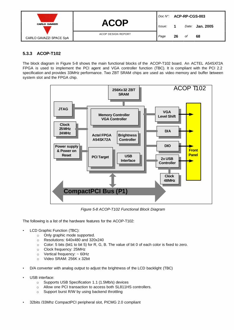
5.3.3 ACOP-T102
The block diagram in Figure 5-8 shows the main functional blocks of the ACOP-T102 board. An ACTEL A54SX72A FPGA is used to implement the PCI agent and VGA controller function (TBC). It is compliant with the PCI 2.2 specification and provides 33MHz performance. Two ZBT SRAM chips are used as video memory and buffer between system slot and the FPGA chip.
ACOP T102
Front Panel
Clock25MHz24MHz
VGALevel Shift
JTAG
PCI Target
256Kx32 ZBTSRAM
CompactPCI Bus (P1)
Power supply & Power on
Reset
Memory ControllerVGA Controller
BrightnessController
USB Interface
D/A
2x USB Controller
Actel FPGAA54SX72A
Clock48MHz
DIO
Figure 5-8 ACOP-T102 Functional Block Diagram
The following is a list of the hardware features for the ACOP-T102: • LCD Graphic Function (TBC):
o Only graphic mode supported. o Resolutions: 640x480 and 320x240 o Color: 5 bits (bit1 to bit 5) for R, G, B. The value of bit 0 of each color is fixed to zero. o Clock frequency: 25MHz o Vertical frequency: ~ 60Hz o Video SRAM: 256K x 32bit
• D/A converter with analog output to adjust the brightness of the LCD backlight (TBC) • USB interface:
o Supports USB Specification 1.1 (1.5Mb/s) devices o Allow one PCI transaction to access both SL811HS controllers. o Support burst R/W by using backend throttling
• 32bits /33Mhz CompactPCI peripheral slot, PICMG 2.0 compliant

Doc N°: ACP-RP-CGS-003
ACOP Issue: 1 Date: Jan. 2005
ACOP DESIGN REPORT Page 27 of 68
5.3.4 ACOP-T103
The ACOP-T103 provides four (4) separate SATA channels to access storage media such as hard disk drive. It uses a PCI-to-Quad-SATA Controller that supports a 32-bit, 66 or 33MHz PCI bus. It accepts host commands through the PCI bus, processes them and transfers data between the host and Serial ATA devices. It can be used to control four independent Serial ATA channels: each channel has its own Serial ATA bus and will support one Serial ATA device with a transfer rate of 1.5 Gbits/sec (150 MBytes/sec). The ACOP-T103 also provides two independent high-performance Fast Ethernet interface controller ports.
ACOP-T103
Front Panel
PCI to Quad STAT controller
CompactPCI Bus (P1)
PCI to Ethernet controller
4x SATA
2X 802.3Clock
Serial EEPROM
Figure 5-9 ACOP-T103 Functional Block Diagram
The following is a list of the hardware features for the ACOP-T103: • PCI to 4-port Serial ATA (SATA) host controller • Serial ATA transfer rate of 1.5Gbit/second • Spread spectrum receiver and single PLL for all channels • Independent 256 byte (32-bit by 64) FIFO per channel • Integrated Serial ATA Link and PHY logic • Compliant with Serial ATA 1.0 specifications • Two IEEE802.3 10/100Base Ethernet ports, Both TX and RX supported • 32bits /33Mhz CompactPCI peripheral slot, PICMG 2.0 compliant

Doc N°: ACP-RP-CGS-003
ACOP Issue: 1 Date: Jan. 2005
ACOP DESIGN REPORT Page 28 of 68
5.3.5 ACOP-BP
The ACOP backplane is compliant to the PICMG 2.0 R3.0 standard for backplane, module connectors, mechanical and power interfaces. CompactPCI signals are routed on P1 connector row only. P2 connectors are installed only on the system slot positions. P3 connector row is not used at all. Each of the CompactPCI segment provides +3.3Vdc signal environment only. All V(I/O) pins of each slot are connected to the corresponding +3.3V power planes. The peripheral interface signals for ACOP specific applications are routed on P4.
5 4 3 2 1
ACOP-SBC (System Slot)
ACOP-T101-T104(Peripheral Slots 1-4)
ACOP-PS
32bit CompactPCI Bus (P1)
P5
P4
P3
P2
P1
Figure 5-10 ACOP-BP Functional Block Diagram
Doc N°: ACP-RP-CGS-003
ACOP Issue: 1 Date: Jan. 2005
ACOP DESIGN REPORT Page 29 of 68
The following is a list of the hardware features for the ACOP-BP: • Compliant with the CompactPCI core specification (PICMG 2.0 R3.0), including the external +12V and -12V power
lines connectors for ground test only. • Support 32-bit, 33 MHz PCI bus operation • 3.3V V(I/O) signaling voltage only • no Hot Swap capability, no Rear I/O capability • 5-slot wide, one system and four I/O slots • Standard 47 pins power supply slot • Position of the AMS-02 specific I/O modules is predefined.

Doc N°: ACP-RP-CGS-003
ACOP Issue: 1 Date: Jan. 2005
ACOP DESIGN REPORT Page 30 of 68
5.3.6 ACOP-PS
The ACOP-PS module is CompactPCI form factor and installed in the backplane. The input voltage range is 24 to 32Vdc, compliant with the +28Vdc power feeder voltage range provided by the EXPRESS Rack. Three outputs (generated by power DC/DC converter implemented with hybrid integrated circuits) provide 3.3Vdc, 5Vdc and 12Vdc power supplies with independent output regulation. The outputs of the ACOP-PS meet the electrical requirements of PICMG specification for CompactPCI systems.
ACOP-PS
Hybrid DCDC converter
(5V)
CompactPCI Bus (47 pins)
Monitor and control
Hybrid DCDC converter
(3.3V)
Hybrid DCDC converter
(12V)
Figure 5-11 ACOP-PS Functional Block Diagram
The following is a list of the hardware features for the ACOP-PS: • Inrush Current: TBD A peak @ TBD Vdc • Efficiency: > 75% @ full load, nominal line • Output Power: TBD watts
+5.06V +/-?3% : TBD A +3.36V +/-?3% : TBD A +12.1V +/-?5% : TBD A
• Protections (TBC): over-voltage, over-current, short-circuit, over temperature and fault isolation • Built-in EMI filters • Backplane power connection via PICMG 2.11 compliant 47-pin power connecter.

Doc N°: ACP-RP-CGS-003
ACOP Issue: 1 Date: Jan. 2005
ACOP DESIGN REPORT Page 31 of 68
5.3.7 LCD MONITOR (TBC)
A Color Active Matrix Liquid Crystal Display (LCD) with an integral Cold Cathode Fluorescent Lamp (CCFL) backlight system will be mounted on the ACOP front panel (TBC). This TFT-LCD has a 6.4 inch diagonally measured active display area with VGA resolution (640 vertical by 480 horizontal pixel array). Each pixel is divided into Red, Green and Blue sub-pixels or dots which are arranged in vertical stripes. A DC/AC inverter is installed inside to provide power for backlight tubes. Backlight tube brightness is adjustable by means of push buttons and software. The following is a list of the hardware features for the LCD module (TBC): • Compatible with VGA-480, VGA-400,VGA-350 and free format. • Screen size 6.4” • Display format 640 x R,G,B x 480 • Display colors: 262,144 • Active area/Outline area = 62.3% • Backlight brightness adjustable 5.3.8 HARD DRIVES
There are four hard drives installed in ACOP providing 20 days of estimated recording time. (Note: Dependent on event rate and size). The four installed hard drives will require periodic replacement by the ISS crew from the onboard stock of empty drives. A batch of 20 hard drives provides 150 days of recording capacity. New batches of hard drives will be delivered by STS and the original master copies of the AMS-02 data will be returned to earth by STS. A dedicated HDD Backplane provides blind mate connectors for the hard drives. Cables are provided to bring power and data connections to this Backplane. The following is a list of the hardware features for the Hard Disk Drives: • Serial ATA with 1.5Gb/sec interface speed • Native Command Queuing • Build-in 16MB cache buffer • Capacity 250 GB or Up 5.3.9 THERMAL SENSORS NETWORK
The thermal sensor network will consist of Dallas one-wire bus devices attached to a single network. The devices will be mounted where appropriate within the ACOP system. Each ACOP-T10x board will have a front panel connector to connect the devices on it. Additionally several sensors will be mounted on the chassis to monitor base plate and hard drive temperatures. The digital I/O (DIO) function will be used to control this bus.

Doc N°: ACP-RP-CGS-003
ACOP Issue: 1 Date: Jan. 2005
ACOP DESIGN REPORT Page 32 of 68
5.3.10 INTERNAL HARNESS
Table 5-1 provides a preliminary list of the internal harness of ACOP. All the cables will be selected for what concerns the current rating according to Para. 7.32 of ECSS-Q-60-11A (TBC).
Cable Type /Size From To
SATA SATA 26-28AWG (TBC) ACOP-T103 Card Front Panel HDD Backplane
Ethernet CAT5 22AWG (TBC) ACOP-T103 Card Front Panel ACOP Front Panel
Fiber Tx1 ISS fiber ACOP-T101 Card Front Panel Through ACOP Front Panel to EXPRESS Rack
Fiber Tx2 ISS fiber ACOP-T101 Card Front Panel Through ACOP Front Panel to EXPRESS Rack
Fiber Rx ISS fiber ACOP-T101 Card Front Panel Through ACOP Front Panel to EXPRESS Rack
External Power 12 AWG ACOP Front Panel ACOP-BP
Push Buttons 20 – 24 AWG (TBC) ACOP Front Panel ACOP-T102 Card Front Panel
LCD Ribbon (TBC) 26 – 28 AWG (TBC) ACOP Front Panel ACOP-T102 Card Front Panel
LCD Power (TBC) 20 – 24 AWG (TBC) ACOP Front Panel ACOP-T102 Card Front Panel
HD Power 20 – 24 AWG (TBC) ACOP-BP HDD Backplane
Table 5-1 ACOP Internal Harness
Doc N°: ACP-RP-CGS-003
ACOP Issue: 1 Date: Jan. 2005
ACOP DESIGN REPORT Page 33 of 68
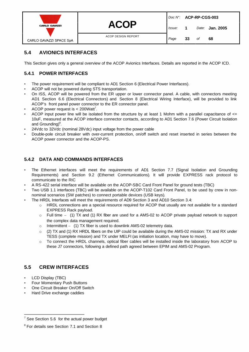
5.4 AVIONICS INTERFACES
This Section gives only a general overview of the ACOP Avionics Interfaces. Details are reported in the ACOP ICD. 5.4.1 POWER INTERFACES
• The power requirement will be compliant to AD1 Section 6 (Electrical Power Interfaces). • ACOP will not be powered during STS transportation. • On ISS, ACOP will be powered from the ER upper or lower connector panel. A cable, with connectors meeting
AD1 Section 6.6 (Electrical Connectors) and Section 8 (Electrical Wiring Interface), will be provided to link ACOP’s front panel power connector to the ER connector panel.
• ACOP power request is < 200Watt7. • ACOP input power line will be isolated from the structure by at least 1 Mohm with a parallel capacitance of <=
10uF, measured at the ACOP interface connector contacts, according to AD1 Section 7.6 (Power Circuit Isolation and Grounding)8.
• 24Vdc to 32Vdc (nominal 28Vdc) input voltage from the power cable • Double-pole circuit breaker with over-current protection, on/off switch and reset inserted in series between the
ACOP power connector and the ACOP-PS. 5.4.2 DATA AND COMMANDS INTERFACES
• The Ethernet interfaces will meet the requirements of AD1 Section 7.7 (Signal Isolation and Grounding Requirements) and Section 9.2 (Ethernet Communications). It will provide EXPRESS rack protocol to communicate to the RIC
• A RS-422 serial interface will be available on the ACOP-SBC Card Front Panel for ground tests (TBC) • Two USB 1.1 interfaces (TBC) will be available on the ACOP-T102 Card Front Panel, to be used by crew in non-
nominal scenarios (SW patches) to connect portable devices (USB keys). • The HRDL Interfaces will meet the requirements of AD9 Section 3 and AD10 Section 3.4:
o HRDL connections are a special resource required for ACOP that usually are not available for a standard EXPRESS Rack payload.
o Full time – (1) TX and (1) RX fiber are used for a AMS-02 to ACOP private payload network to support the complex data management required.
o Intermittent – (1) TX fiber is used to downlink AMS-02 telemetry data. o (2) TX and (1) RX HRDL fibers on the UIP could be available during the AMS-02 mission: TX and RX under
TESS (complete mission) and TX under MELFI (as initiation location, may have to move). o To connect the HRDL channels, optical fiber cables will be installed inside the laboratory from ACOP to
these J7 connectors, following a defined path agreed between EPIM and AMS-02 Program. 5.5 CREW INTERFACES
• LCD Display (TBC) • Four Momentary Push Buttons • One Circuit Breaker On/Off Switch • Hard Drive exchange caddies
7 See Section 5.6 for the actual power budget 8 For details see Section 7.1 and Section 8

Doc N°: ACP-RP-CGS-003
ACOP Issue: 1 Date: Jan. 2005
ACOP DESIGN REPORT Page 34 of 68
5.6 POWER BUDGET
The following table shows the power budget for the major components of ACOP.
Power consumption (W)
Item Stand-by
Operative (average)
Operative (peak)
Remarks
ACOP-SBC - 9.90 -
ACOP-T101 - 1.65 -
ACOP-T102 - 1.65 -
ACOP-T103 - 5.00 -
Spare Slot - 0 -
ACOP-PS - 11.35 -
ACOP-LCD (TBC) - 6.30 -
HDD19 0.72 - 12.54
HDD2 0.72 - 12.54
HDD3 0.72 - 12.54
HDD4 0.72 - 12.54
Table 5-2 Power Budget
5.6.1 OPERATIVE CASE – POWERED DOWN
In this case ACOP has its power switch in the off position.
Item Power Consumption (W) Remarks
ACOP-SBC 0
ACOP-T101 0
ACOP-T102 0
ACOP-T103 0
Spare Slot 0
ACOP-PS 0
ACOP-LCD (TBC) 0
HDD1 0
HDD2 0
HDD3 0
HDD4 0
Total 0
Table 5-3 Operative Case – Powered Down
9 Nominal one or two drives operative

Doc N°: ACP-RP-CGS-003
ACOP Issue: 1 Date: Jan. 2005
ACOP DESIGN REPORT Page 35 of 68
5.6.2 OPERATIVE CASE – COLD START
In this case ACOP has just received power and is awaiting commands.
Item Power Consumption (W) Remarks
ACOP-SBC 9.90
ACOP-T101 1.65
ACOP-T102 1.65
ACOP-T103 5.00
Spare Slot 0.00
ACOP-PS 11.35
ACOP-LCD (TBC) 6.30
HDD1 0.72
HDD2 0.72
HDD3 0.72
HDD4 0.72
Total 38.73
Table 5-4 Operative Case – Cold Start
5.6.3 OPERATIVE CASE – WARM START
In this case ACOP has just reset and is reloading the system.
Item Power Consumption (W) Remarks
ACOP-SBC 9.90
ACOP-T101 1.65
ACOP-T102 1.65
ACOP-T103 5.00
Spare Slot 0.00
ACOP-PS 11.35
ACOP-LCD (TBC) 6.30
HDD1 0.72
HDD2 0.72
HDD3 0.72
HDD4 0.72
Total 38.73
Table 5-5 Operative Case – Warm Start

Doc N°: ACP-RP-CGS-003
ACOP Issue: 1 Date: Jan. 2005
ACOP DESIGN REPORT Page 36 of 68
5.6.4 OPERATIVE CASE – ACTIVE IDLE
In this case ACOP has loaded LINUX but the application software is idle.
Item Power Consumption (W) Remarks
ACOP-SBC 9.90
ACOP-T101 1.65
ACOP-T102 1.65
ACOP-T103 5.00
Spare Slot 0.00
ACOP-PS 11.35
ACOP-LCD (TBC) 6.30
HDD1 0.72
HDD2 0.72
HDD3 0.72
HDD4 0.72
Total 38.73
Table 5-6 Operative Case – Active Idle
5.6.5 OPERATIVE CASE – ACTIVE RECORD
The ACOP application is actively recording data.
Item Power Consumption (W) Remarks
ACOP-SBC 9.90
ACOP-T101 1.65
ACOP-T102 1.65
ACOP-T103 5.00
Spare Slot 0.00
ACOP-PS 11.35
ACOP-LCD (TBC) 6.30
HDD1 8.20 Estimated duty cycle, typical HD
HDD2 0.72
HDD3 0.72
HDD4 0.72
Total 46.21
Table 5-7 Operative Case – Active Record

Doc N°: ACP-RP-CGS-003
ACOP Issue: 1 Date: Jan. 2005
ACOP DESIGN REPORT Page 37 of 68
5.6.6 OPERATIVE CASE – ACTIVE PLAYBACK
The ACOP application is actively playing back data.
Item Power Consumption (W) Remarks
ACOP-SBC 9.90
ACOP-T101 1.65
ACOP-T102 1.65
ACOP-T103 5.00
Spare Slot 0.00
ACOP-PS 11.35
ACOP-LCD (TBC) 6.30
HDD1 8.20 Estimated duty cycle, typical HD.
HDD2 0.72
HDD3 0.72
HDD4 0.72
Total 46.21
Table 5-8 Operative Case – Active Playback
5.6.7 OPERATIVE CASE – ACTIVE RECORD AND PLAYBACK
The ACOP application is both recording and playing back data from different hard drives.
Item Power Consumption (W) Remarks
ACOP-SBC 9.90
ACOP-T101 1.65
ACOP-T102 1.65
ACOP-T103 5.00
Spare Slot 0.00
ACOP-PS 11.35
ACOP-LCD (TBC) 6.30
HDD1 8.20 Estimated duty cycle, typical HD.
HDD2 8.20 Estimated duty cycle, typical HD.
HDD3 0.72
HDD4 0.72
Total 53.69
Table 5-9 Operative Case – Active Record and Playback

Doc N°: ACP-RP-CGS-003
ACOP Issue: 1 Date: Jan. 2005
ACOP DESIGN REPORT Page 38 of 68
6. EMC REQUIREMENTS ASSESMENT AND VERIFICATION APPROACH
This section provides the list of the EMC and bonding-grounding requirements applicable to ACOP and the identification of the verification type to be applied. 6.1.1 EMC APPLICABLE DOCUMENTS
The AD1 Sections 7.1, 7.3 and 7.4 contain all the requirements that ACOP shall to be compliant with. Sections 7.2, 7.4.1, and 7.4.2 has not to be considered applicable due to the fact ACOP will be transported inside the Shuttle in power off condition. 6.1.1.1 EMC VERIFICATION
Verification of the applicable requirements given in AD1 will be carried out by test and/or review of design and/or analysis as defined in AD13. 6.1.2 EMC REQUIREMENTS
6.1.2.1 CE 01 CONDUCTED EMISSION REQUIREMENT
The ACOP shall comply with the narrow band emission between 30 Hz and 15 KHz on the DC current leads as specified in the AD1 Section 7.3.1.3.1. The emission limit shall be established considering that the ACOP requires an input current of 2.5 A (TBC) on the 28Vdc nominal inlet (70W @28Vdc). 6.1.2.1.1 CE 01 VERIFICATION
The verification of the CE 01 EMC requirement shall be carried out in accordance with the requirements defined in the AD1 Section 7.3.1.3.2 The test shall be carried out in the noisiest operating mode 6.1.2.2 CE 03 CONDUCTED EMISSIONS
6.1.2.2.1 CE 03 REQUIREMENTS
ACOP shall comply with the narrow band emission between 15 KHz and 50 MHz on the DC current leads as specified in the AD1 Section 7.3.1.3.3 The emission limit shall be established considering that the unit requires the input current already specified in previous paragraphs. 6.1.2.2.2 CE 03 VERIFICATION
The verification of the CE 03 EMC requirement shall be carried out in accordance with the requirements defined in the AD1 Section 7.3.1.3.4 The test shall be carried out in the noisiest operating mode

Doc N°: ACP-RP-CGS-003
ACOP Issue: 1 Date: Jan. 2005
ACOP DESIGN REPORT Page 39 of 68
6.1.2.3 CE 07 CONDUCTED EMISSIONS
6.1.2.3.1 CE 07 REQUIREMENTS
ACOP shall comply with the direct current input power leads spikes (in the time domain) as indicated in the AD1 Section 7.3.1.3.5. The purpose of the test is to measure in the time domain the unit induced effect on the input DC power quality, caused by cycling the ACOP power and changing the operating modes. 6.1.2.3.2 CE 07 VERIFICATION
The verification of the CE 07 EMC requirement shall be carried out in accordance with the requirements defined in the AD1 Section 7.3.1.3.6 6.1.2.4 CS01 CONDUCTED SUSCEPTIBILITY
6.1.2.4.1 CS 01 REQUIREMENT (30 HZ – 50 KHZ)
The ACOP Payload shall not produce an unsafe condition or one that could result in damage to ISS equipment or payload hardware and shall operate within the specification without performance degradation when subjected to electromagnetic energy injected on the power leads as specified in AD1 Section 7.3.1.4.2 6.1.2.4.2 CS 01 VERIFICATION
The verification of the CS 01 requirement shall be carried out in accordance with the directions given at Section 3.2.2.1 of the SSP-30238 6.1.2.5 CS 02 CONDUCTED SUSCEPTIBILITY
6.1.2.5.1 CS 02 REQUIREMENT (50 KHZ – 50 MHZ)
The ACOP shall not produce an unsafe condition or one that could result in damage to ISS equipment or payload hardware and shall operate within the specification without performance degradation when subjected to electromagnetic energy injected on the power leads as specified in AD1 Section 7.3.1.4.4. 6.1.2.5.2 CS02 VERIFICATION
The verification of the CS 02 requirement will be carried out in accordance with the Section 3.2.2.2 of the SSP-30238.

Doc N°: ACP-RP-CGS-003
ACOP Issue: 1 Date: Jan. 2005
ACOP DESIGN REPORT Page 40 of 68
6.1.2.6 CS 06 CONDUCTED SUSCEPTIBILITY
6.1.2.6.1 CS 06 REQUIREMENT
The ACOP shall not produce an unsafe condition or one that could result in damage to ISS equipment or payload hardware and shall operate within the specification without performance degradation when subjected to electromagnetic energy injected on the power leads as specified in AD1 Section 7.3.1.4.6. 6.1.2.6.2 CS 06 VERIFICATION
The verification of the CS 06 requirement will be carried out by test in accordance with the Section 3.2.2.3 of the SSP-30238. 6.1.2.7 RE 02 RADIATED EMISSIONS
Electric field, 14 KHz – 10 GHz (narrow band), 13,5 – 15,5 GHz 6.1.2.7.1 RE 02 REQUIREMENT
ACOP shall not radiate in excess of the values specified in AD1 Section 7.3.1.5.4. 6.1.2.7.2 RE 02 VERIFICATION
The verification of the compliance with the RE 02 requirement shall be carried out by test, in accordance with the Section 3.2.3.1 of the SSP-30238. 6.1.2.8 RS 02 RADIATED SUSCEPTIBILITY
Magnetic induction field 6.1.2.8.1 RS 02 REQUIREMENT
The ACOP shall not produce an unsafe condition or one that could result in damage to ISS equipment or payload hardware when subjected sequentially when subjected to the test spikes specified in AD1 Section 7.3.1.6.3. 6.1.2.8.2 RS 02 VERIFICATION
The verification of the compliance with the RS02 requirement will be carried out by test. The test will be executed in accordance with the instructions given in Section 3.2.4.1 of the SSP-30238

Doc N°: ACP-RP-CGS-003
ACOP Issue: 1 Date: Jan. 2005
ACOP DESIGN REPORT Page 41 of 68
6.1.2.9 RS 03 RADIATED SUSCEPTIBILITY
Electric field, 14 KHz to 20 GHz 6.1.2.9.1 RS 03 REQUIREMENTS
The ACOP shall not produce an unsafe condition or one that could result in damage to ISS equipment or payload hardware when subjected to the radiated electric field less than or equal to the values specified in AD1 Section 7.3.1.7.2. 6.1.2.9.2 RS 03 VERIFICATION
The RS03 requirement will be verified by test in accordance with the instructions given at Section 3.2.4.2 of the SSP-30238. Since the unit is a digital equipment the requirement of Section 3.2.4.2.3.9.3 is considered applicable for the modulation. 6.1.3 ADDITIONAL REQUIREMENTS
6.1.3.1 CORONA EFFECTS
6.1.3.1.1 CORONA REQUIREMENT
The ACOP shall be designed to preclude damaging by the corona effect in any ISS operating condition
6.1.3.1.2 CORONA VERIFICATION
It is understood that the compliance with the requirement defined in AD1 Section 7.3.2.3 is verified by the absence of corona effects during functional test. 6.1.3.2 STATIC ELECTRICITY
6.1.3.2.1 ELECTROSTATIC DISCHARGE REQUIREMENT
The un-powered ACOP shall not be damaged by electrostatic discharge (ESD) equal to or less than 4KV applied to the case or to any pin on external connectors. If the ACOP may be damaged by ESD between 4 KV and 15 KV, they must have a label placed on the case in a location clearly visible in the installed position. Handling and labeling of the units susceptible to ESD up to 15 KV shall be in accordance with MIL-STD-1686A 6.1.3.2.2 ESD VERIFICATION
The verification will be carried out by analysis or test. The ESD will be simulated by charging a 100pF capacitor and discharging it through a 1500 Ω resistor

Doc N°: ACP-RP-CGS-003
ACOP Issue: 1 Date: Jan. 2005
ACOP DESIGN REPORT Page 42 of 68
6.1.3.3 LIGHTNING
6.1.3.3.1 LIGHTNING REQUIREMENT
ACOP shall be designed so that a failure due to a lightning strike will not propagate to the MPLM or the ISS 6.1.3.3.2 LIGHTNING VERIFICATION
The verification that the payload is designed to meet the lightning produced magnetic fields environment of the payload bay as specified in the IDD will be performed by analysis based on RS02 test results as suggested by AD13. 6.1.3.4 MAGNETIC FIELDS
6.1.3.4.1 MAGNETIC FIELDS FOR EXPRESS RACK PAYLOADS IN THE ISS REQUIREMENTS
ACOP shall not generate AC or DC magnetic fields greater than the limits defined in AD1 Sections 7.4.3.1 and 7.4.3.2. 6.1.3.4.2 MAGNETIC FIELDS FOR EXPRESS RACK PAYLOADS IN THE ISS VERFICATION
The requirements will be verified by test. 6.1.4 GROUNDING & BONDING
6.1.4.1 GROUNDING & BONDING REQUIREMENTS
ACOP shall meet the grounding and bonding requirements given in AD1 Sections 7.5 – 7.7 and in particular: • ACOP shall be inserted and fixed into a Locker location of an EXPRESS Rack before being powered on • ACOP will use the single point ground approach for the internally DC/DC generated secondary power lines (cPCI
voltages, Hard Disk Drives voltages). • the EXPRESS Rack 28Vdc primary power line will be maintained isolated from the ACOP chassis/structure by a
minimum of 1 Mohm in parallel with a capacitance less than 10uF. • the Express Rack 28Vdc primary power line will be kept isolated from ACOP secondary power voltages by a
minimum of 1 Mohm 6.1.4.2 GROUNDING & BONDING VERIFICATION
Verification of the applicable requirements given in AD1 will be carried out by test and/or review of design and/or analysis as defined in AD13.

Doc N°: ACP-RP-CGS-003
ACOP Issue: 1 Date: Jan. 2005
ACOP DESIGN REPORT Page 43 of 68
7. EMC ANALYSIS
7.1 GROUNDING / BONDING / ISOLATION
The ACOP electronics is housed in an aluminum box (AL 7075). The parts of the box are electrically connected together in order to offer a low impedance path, therefore the mechanical box will operate as a shield against the internally generated emissions and the externally generated emissions. The ACOP shall be bonded via the bond path present in the EXPRESS Rack-to-payload power connector (pin D). The ACOP bonding class is R ( Radio Frequency Bond-RF).
The bonding path to the Express Rack will allow : • to conduct electrical faults current without creating thermal or electrical hazard • to minimize differences in potential between all equipment. The ACOP internal power lines are derived from the 28Vdc input line. The 28Vdc input line will be kept isolated from ground/structure by at least 1 Mohm (this applies to the alive and return line), in parallel with a capacitance of less than 10uF, according to AD1 Section 7.6 (Power Circuit Isolation and Grounding). The 28Vdc input line will be also isolated from the ACOP internal DC/DC generated power supplies by at least 1Mohm. The Ethernet connection with the EXPRESS Rack RIC will be as per AD1 Section 7.7 (Signal Isolation and Grounding Requirements) for isolation and grounding. The HRDL interfaces will use optic fiber cables as physical layer, therefore there will not be electrical connections. One RS 422 Interface will be present only for ground test (TBC). Two USB 1.1 (TBC) ports will be present to be used by crew in non-nominal scenarios (SW patches) to connect portable devices (USB keys) 7.2 IN – RUSH CURRENT
In order to limit the in–rush current at the ACOP electronic “power on” the DC/DC converters connected on the nominal 28Vdc input line are equipped with a current limiter which has a two fold function: • to limit the current drained from the 28Vdc nominal inlet at the power on • to protect against short circuit occurring in the DC/DC converters during nominal operation (TBD) The maximum specified power for ACOP in the operative mode is 70 watt (TBC).

Doc N°: ACP-RP-CGS-003
ACOP Issue: 1 Date: Jan. 2005
ACOP DESIGN REPORT Page 44 of 68
7.3 CONDUCTED AND RADIATED EMISSION SOURCES
The main sources of conducted/radiated emissions are:
• ACOP DC/DC converters to generate the ACOP internal voltages for the cPCI boards and the HDDs • cPCI bus traffic running at 33 MHz on the 5 slots ACOP-BP • ACOP Single Board Computer • Hard Disk Drives (in particular the disk motor control sections) • LCD High Voltage Inverter (TBC) In particular, the following clock frequencies are present in ACOP: • 50 MHz oscillator for the HRDL board ACOP-T101 • 100-110 KHz (TBC) of the DC/DC converters control logic. • 50 MHz oscillator (TBC) for the FPGA implementing the SATA interface • 66 and 33 MHz for the ACOP-SBC board (66 MHz for the Power PC chip and 33 MHz for the cPCI Interface) • 24-25 MHz oscillator for the FPGA implementing the VGA control logic (TBC) • 48 MHz for the USB Controller • 50 MHz oscillator (TBC) for the FPGA implementing the Ethernet Interface

Doc N°: ACP-RP-CGS-003
ACOP Issue: 1 Date: Jan. 2005
ACOP DESIGN REPORT Page 45 of 68
8. GROUNDING PHILOSOPHY
The ACOP avionics, with respect to the overall grounding system, shall be based on the following concepts: • The primary electrical power shall be isolated from ACOP chassis by a minimum of 1 Mohm in parallel with a
capacitance less than 10uF. • Implementation of a galvanic isolation between the primary power bus and all the secondary internal or distributed
powers (greater than 1 Mohm) • All the secondary power references shall be connected together and to the ACOP structure in a single point
represented by an internal bonding stud. • The metallic shells of all the ACOP external electrical connectors shall be electrically bonded to the ACOP
bulkhead mount connector or the ACOP front panel case, with a DC resistance of less than 2.5 milliohms per joint.
The primary payload bond path for ACOP shall be through the EXPRESS Rack-to-payload power connector interface (pin D, see Table 8-1). Nevertheless a bonding stud will be implemented on the ACOP Front Panel to allow the single point connection of the internal secondary power references (internal side of the ACOP Front Panel) and eventually to connect an external bonding strap between ACOP and the EXPRESS Rack (external side of the front panel). An internal to the ACOP Front Panel bonding strap will connect the movable part of the ACOP Front Panel to the fixed part (the bonding between the two parts of the ACOP Front Panel will not rely only on the friction hinge)
EXPRESS CABLE CONNECTOR: NB6GE14 4SNT MATING CONNECTOR: NB0E14 4PNT
PIN FUNCTION AWG SIGNAL NAME COMMENT
A +28 V Power 12 Power
B Not Used 12 N/A
C 28 V Return 12 Power Return
D Ground 12 Ground
Table 8-1 Power Connector Pin Function

Doc N°: ACP-RP-CGS-003
ACOP Issue: 1 Date: Jan. 2005
ACOP DESIGN REPORT Page 46 of 68
In Figure 8-1 the ACOP grounding philosophy is shown.
Figure 8-1 ACOP Grounding Philosophy
> 1 Mohm
28Vdc Primary Inlet Internal VoltagesCircuit Breaker
> 1 Mohm < 10 uF
optic fiber
optic fiber
HRDL TX
HRDL RX
Ethernet TX
Ethernet RX
Bonding via power connector bond
ACOP
pinA
pinC
pinD
Bonding stud

Doc N°: ACP-RP-CGS-003
ACOP Issue: 1 Date: Jan. 2005
ACOP DESIGN REPORT Page 47 of 68
9. SOFTWARE
9.1 SCOPE OF THE SOFTWARE
ACOP-SW is the entire body of embedded software running on the ACOP hardware. ACOP-SW consists of three components:
1) ACOP-SYS-SW providing low level functionality 2) ACOP-APP-SW providing the mission explicit application software functions on the ACOP hardware 3) ACOP-ERL-SW software developed by the ACOP project but which executes on the EXPRESS Rack Laptop
9.1.1 ACOP-SYS-SW
Implements the following main functions : 1. BootROM monitor providing boot strapping operations and low level file transfer functions. 2. Initialization of the ACOP hardware. 3. Operations of the ACOP hardware interfaces via device drivers. 4. Exception handling. 5. Diagnostic and system self-tests. 6. Management of data storage devices and file systems. 7. External command processing for system commands. 8. Execution and control of ACOP-APP-SW. 9.1.2 ACOP-ERL-SW
Implements the following main functions: 1. Implements a ISS crew interface on the EXPRESS Rack Laptop. 9.1.3 ACOP-APP-SW
Implements the following main functions: 1. Monitoring of resources and environment relevant to ACOP Health and Status. 9. Functional interfaces to ISS avionics C&DH systems. 2. Functional interfaces to the ISS HRDL interfaces. 3. Data recording. 4. Data playback. 5. Detailed data management. 6. Detailed management of data contents with regard to external systems. 7. External command processing for applications commands.

Doc N°: ACP-RP-CGS-003
ACOP Issue: 1 Date: Jan. 2005
ACOP DESIGN REPORT Page 48 of 68
9.2 ACOP-SYS-SW – OPERATING SYSTEM LEVEL SUPPORT
9.2.1 BOOTROM MONITOR
Based on eCos, a open source embedded operating system. The BootRom monitor resides in the read only BootProm. This is brought to execution whenever the processor exits the reset state. eCos has been designed to support applications with real-time requirements, providing features such as full preemptability, minimal interrupt latencies, and all the necessary synchronization primitives, scheduling policies and interrupt handling mechanisms. eCos also provides all the functionality required for general embedded application support including device drivers, memory management, exception handling, C, math libraries, etc. In addition to runtime support, the eCos system includes all the tools necessary to develop embedded applications, including eCos software configuration and build tools, and GNU-based compilers, assemblers, linkers, debuggers, and simulators. eCos provides the following functionality: • Hardware Abstraction Layer (HAL) • Real-time kernel
o Interrupt handling o Exception handling o Choice of schedulers o Thread support o Rich set of synchronization primitives o Timers, counters and alarms o Choice of memory allocators o Debug and instrumentation support
• µITRON 3.0 compatible API • POSIX compatible API • ISO C and math libraries • libstdc++ library • Serial, ethernet, wallclock and watchdog device drivers • USB slave support • TCP/IP networking stacks, including
o Bootp/DHCP o DNS o TFTP/FTP o SNMP o IPv6 o HTTPD o PPP
• File systems: o Journalling Flash File System (JFFS2) o RAM filing system o ROM filing system
• Graphics libraries, including o Portable Embedded GUI Library o Microwindows o VNC Server
• Power management • GDB debug support

Doc N°: ACP-RP-CGS-003
ACOP Issue: 1 Date: Jan. 2005
ACOP DESIGN REPORT Page 49 of 68
9.2.2 LINUX OPERATING SYSTEM KERNEL
Based on the LINUX 2.6 kernel providing applications services. Note: What is called out here is just the LINUX kernel, not a full distribution of a whole LINUX system. As an embedded system ACOP will only utilize the LINUX kernel plus a command utility program. The ACOP-SYS-SW will provide the LINUX 2.6 kernel offer key performance enhancements for near-real-time systems. • General new features
o Pre-emptable Kernel o O(1) Scheduler o New Kernel Device Structure (kdev_t) o Improved Posix Threading Support (NGPT and NPTL) o New Driver Model & Unified Device Structure o Faster Internal Clock Frequency o Paring Down the BKL (Big Kernel Lock) o Better in Place Kernel Debugging o Smarter IRQ Balancing o ACPI Improvements o Software Suspend to Disk and RAM o Support for USB 2.0 o ALSA (Advanced Linux Sound Architecture) o LSM (Linux Security Module) o Hardware Sensors Driver (lm-sensors)
• New features, Architectures
o AMD 64-bit (x86-64) o PowerPC 64-bit (ppc64) o User Mode Linux (UML)
• New features, Filesystems
o Ext3, ReiserFS (already in 2.4) o JFS (IBM) o XFS (SGI)
• New features, I/O Layer
o Rewrite of Block I/O Layer (BIO) o Rewrite of Buffer Layer o Asynchronous I/O o IDE Layer Update o ACL Support (Access Control List) o New NTFS Driver
• New features, Networking
o NFS v4 o Zero-Copy NFS o TCP Segmentation Offload o SCTP Support (Stream Control Transmission Protocol) o Bluetooth Support (not experimental) o NAPI (Network Interrupt Mitigation)

Doc N°: ACP-RP-CGS-003
ACOP Issue: 1 Date: Jan. 2005
ACOP DESIGN REPORT Page 50 of 68
9.2.3 LINUX HRDL DEVICE DRIVER
Kernel driver module for LINUX to support basic access to the ACOP_HRDL interface. 9.2.4 LINUX HARD DRIVE DEVICE DRIVER
Kernel driver module, plus file system support and S.M.A.R.T., for LINUX EXT3 access to hard drives. 9.2.5 LINUX USB HOST DEVICE DRIVER
Kernel driver, plus device support, for USB storage devices. 9.2.6 LINUX VIDEO DEVICE DRIVER
Kernel driver for basic frame buffer video device support. 9.2.7 BUSYBOX - COMMAND INTERFACE
This utility provides command line interface and support for various functions within the LINUX environment. 9.2.7.1 BUSYBOX FEATURES
BusyBox combines tiny versions of many common UNIX utilities into a single small executable. It provides minimalist replacements for most of the utilities you usually find in GNU coreutils, util-linux, etc. The utilities in BusyBox generally have fewer options than their full-featured GNU cousins; however, the options that are included provide the expected functionality and behave very much like their GNU counterparts. BusyBox has been written with size-optimization and limited resources in mind. It is also extremely modular so you can easily include or exclude commands (or features) at compile time. This makes it easy to customize your embedded systems. To create a working system, just add /dev, /etc, and a Linux kernel. BusyBox provides a fairly complete POSIX environment for any small or embedded system. BusyBox is extremely configurable. This allows you to include only the components you need, thereby reducing binary size. Run 'make config' or 'make menuconfig' to select the functionality that you wish to enable. The run 'make' to compile BusyBox using your configuration. Commands supported include: addgroup, adduser, adjtimex, ar, arping, ash, awk, basename, bunzip2, busybox, bzcat, cal, cat, chgrp, chmod, chown, chroot, chvt, clear, cmp, cp, cpio, crond, crontab, cut, date, dc, dd, deallocvt, delgroup, deluser, devfsd, df, dirname, dmesg, dos2unix, dpkg, dpkg-deb, du, dumpkmap, dumpleases, echo, egrep, env, expr, false, fbset, fdflush, fdformat, fdisk, fgrep, find, fold, free, freeramdisk, fsck.minix, ftpget, ftpput, getopt, getty, grep, gunzip, gzip, halt, hdparm, head, hexdump, hostid, hostname, httpd, hush, hwclock, id, ifconfig, ifdown, ifup, inetd, init, insmod, install, ip, ipaddr, ipcalc, iplink, iproute, iptunnel, kill, killall, klogd, lash, last, length, linuxrc, ln, loadfont, loadkmap, logger, login, logname, logread, losetup, ls, lsmod, makedevs, md5sum, mesg, mkdir, mkfifo, mkfs.minix, mknod, mkswap, mktemp, modprobe, more, mount, msh, mt, mv, nameif, nc, netstat, nslookup, od, openvt, passwd, patch, pidof, ping, ping6, pipe_progress, pivot_root, poweroff, printf, ps, pwd, rdate, readlink, realpath, reboot, renice, reset, rm, rmdir, rmmod, route, rpm, rpm2cpio, run-parts, rx, sed, seq, setkeycodes, sha1sum, sleep, sort, start-stop-daemon, strings, stty, su, sulogin, swapoff, swapon, sync, sysctl, syslogd, tail, tar, tee, telnet, telnetd, test, tftp, time, top, touch, tr, traceroute, true, tty, udhcpc, udhcpd, umount, uname, uncompress, uniq, unix2dos, unzip, uptime, usleep, uudecode, uuencode, vconfig, vi, vlock, watch, watchdog, wc, wget, which, who, whoami, xargs, yes, zcat
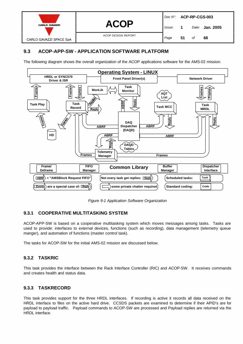
Doc N°: ACP-RP-CGS-003
ACOP Issue: 1 Date: Jan. 2005
ACOP DESIGN REPORT Page 51 of 68
9.3 ACOP-APP-SW - APPLICATION SOFTWARE PLATFORM
The following diagram shows the overall organization of the ACOP applications software for the AMS-02 mission.
Figure 9-1 Application Software Organization
9.3.1 COOPERATIVE MULTITASKING SYSTEM
ACOP-APP-SW is based on a cooperative multitasking system which moves messages among tasks. Tasks are used to provide: interfaces to external devices, functions (such as recording), data management (telemetry queue manger), and automation of functions (master control task). The tasks for ACOP-SW for the initial AMS-02 mission are discussed below. 9.3.2 TASKRIC
This task provides the interface between the Rack Interface Controller (RIC) and ACOP-SW. It receives commands and creates health and status data. 9.3.3 TASKRECORD
This task provides support for the three HRDL interfaces. If recording is active it records all data received on the HRDL interface to files on the active hard drive. CCSDS packets are examined to determine if their APID’s are for payload to payload traffic. Payload commands to ACOP-SW are processed and Payload replies are returned via the HRDL interface.
TaskRecord
DAQDispatcher
(DAQD)
Task MCC
Operating System - LINUX
DAQDTables
Common LibraryFrame/Deframe
FIFOManager
BufferManager
DispatcherInterface
XQTList
ABRFABRF
Frames
HRDL or SYNC570Driver & ISR
Rep
ly
= "AMSBlock Request FIFO"ABRF
some private chatter required
Not every task get replies: Reply
TelemetryManager
Scheduled tasks: Task
Standard coding: Code are a special case of: ReplyEvents
Task Play TaskMRDL
ABRF
Network Driver
Frames
Fra
mes
Fra
mes
HD
Fra
mes
Fra
mes
Fra
mes
Fram
es
Fram
es
TaskMonitor
Front Panel Driver(s)
AB
RF
Rep
ly
MonLibRe
plies
ABRF
Rep
ly
Rep
ly
Reply
Doc N°: ACP-RP-CGS-003
ACOP Issue: 1 Date: Jan. 2005
ACOP DESIGN REPORT Page 52 of 68
9.3.4 TASKMCT
This task provides support for scheduled activities such as gather data for health and status. 9.3.5 TASKTQM
This task provides consistent telemetry queue management for all external interfaces. 9.3.6 TASKXFER
This task provides for file transfer protocols within the ACOP telemetry streams. 9.3.7 TASKWDT
This task manages the ACOP watch dog timer. 9.3.8 TASKFEP
This task provides the generic network interface to support network attached requests such as from the ERL. 9.4 SOFTWARE DEVELOPMENT ENVIRONMENT
The ACOP-SW development directly occurs on standard laptop systems operating with the LINUX operating system. The ACOP-SW is developed using the standard cross development tools provided by GNU. Executables generated within this environment are transferred by the network to the ACOP for testing. Networked based graphical debug tools are available.

Doc N°: ACP-RP-CGS-003
ACOP Issue: 1 Date: Jan. 2005
ACOP DESIGN REPORT Page 53 of 68
10. MECHANICAL DESIGN
10.1 REQUIREMENTS AND CONSTRAINTS
10.1.1 LOCATION ? SSP52000-IDD-ERP P3-5~P3-11?
ACOP shall be installed in the location of MDL of EXPRESS Rack as shown in the following figure and should blind mate with the back plate of the rack.
Figure 10-1 Location and configuration of ACOP
10.1.2 DIMENSION (SSP52000-IDD-ERP P3-18)
The ACOP envelope shall meet the Mid Deck Locker (MDL) envelope. 10.1.3 PAYLOAD ZERO-G REQUIREMENT ? SSP52000-IDD-ERP P3-14)
ACOP shall have a zero-G retention feature to prevent any equipment from floating out of the tray/locker during on-orbit activities. 10.1.4 MAIN ELECTRICAL PARTS
• 5 CompactPCI cards • 1 Power Supply section • 4 Hard Drives • 1 LCD (TBC) • Backplane • Cable harness

Doc N°: ACP-RP-CGS-003
ACOP Issue: 1 Date: Jan. 2005
ACOP DESIGN REPORT Page 54 of 68
10.1.5 ACCESSIBILITY TO HARD DRIVES FOR REPLACEMENT
The four installed hard drives will require periodic replacement by the ISS crew from the onboard stock of empty drives (to be replaced about every 20 days.) 10.1.6 MAIN FRONT PANEL REQUIREMENT
The main ACOP Front Panel (that is the part to be opened) shall be mounted with LCD (TBC) and can be opened with friction hinge. It is locked by four 1/4 fasteners and one magnetic latch, two of those 1/4 fasteners (on the middle of both sides of the door) may be cancelled if further structure analysis is proved safe. 10.1.7 FIXED FRONT PANEL REQUIREMENT
The fixed part of the ACOP Front Panel shall be mounted with: • Four Momentary Push Buttons • One Circuit Breaker On/Off Switch • One HRDL Connector • One Power Connector • One MRDL Connector
10.1.8 STRUCTURAL LOAD FACTORS AND ANALYSIS (SSP 52000-IDD-ERP SSP52005-IDD-ER)
ACOP structure shall meet the load factors defined in AD1 Section 4 by using the methodology defined in SSP- 52005. 10.1.9 STRUCTURAL SAFETY FACTOR (SSP 52000-IDD-ERP CHAP 4)
ACOP structural safety factor shall require 1.25 for yield, and 2.0 for ultimate.
10.1.10 STRUCTURAL FIRST NATURAL FREQUENCE (SSP 52000-IDD-ERP CHAP 4)
First natural frequency of ACOP shall exceed 35Hz. 10.1.11 THERMAL DESIGN AND LIMIT (SSP 52000-IDD-ERP CHAP 5)
ACOP shall meet the temperature limit defined in AD1.

Doc N°: ACP-RP-CGS-003
ACOP Issue: 1 Date: Jan. 2005
ACOP DESIGN REPORT Page 55 of 68
10.2 MECHANICAL ARCHITECTURE
The mechanical structure of ACOP is mainly constructed by an outer structure (LOCKER) and an inner structure (CHASSIS). The locker will be mounted to the back-plate of the EXPRESS Rack and the chassis will support the electrical components. 10.2.1 MECHANICAL STRUCTURE
The main mechanical parts of ACOP are listed below:
Item Function Quantity Remarks
LOCKER Outer structure (shell) of ACOP. Structure interface to back-plate of EXPRESS Rack
1 set Assembly of 6 plates and 4 beams, integrated by flat head #4 screws
FRONT PANEL (Fixed) Part of LOCKER. Support of all I/O connectors.
1 piece
FRONT PANEL (Opening) To be opened for Hard Drives replacement. Location of LCD (TBC)
1 piece Opened with friction hinge, closed by 1/4 Turn fasteners
CHASSIS Inner structure of ACOP. Support of electric components. Fins for heat dissipation
1 piece
Produced by wire cutting, all in one piece. It will be fixed to the locker by means of flat head screws size # 6 or #8 (TBC).
SIDE PLATE Enclose airflow inside the fin channels. Prevent occurrence of turbulence in front space.
2 pieces Fixed with CHASSIS by #4 flat head screws
BP FRAME Stiffener for the Backplane. Avoid Backplane bending when the boards’ connectors are plugged in.
1 piece Integrated with the Backplane by screws.
DUCT Air duct for air inlet and outlet. Airflow channels between CHASSIS and LOCKER
2 sets Made from metal plate, integrated with CHASSIS and LOCKER by #4 flat head screws
CADDY Frame for HD. Heat sink and path of HD
4 pieces
AIR FILTER Filter for airflow 2 pieces Mounted from outside of LOCKER back-plate
Table 10-1 Main Mechanical Parts

Doc N°: ACP-RP-CGS-003
ACOP Issue: 1 Date: Jan. 2005
ACOP DESIGN REPORT Page 56 of 68
Figure 10-2 Mechanical Main parts of ACOP
10.2.2 ELECTRICAL COMPONENTS LAY OUT
There are 4 Hard Drives installed in the upper part of the Chassis and 5 cPCI boards with 1 power supply board installed in the lower part of the Chassis.
Figure 10-3 Electric Main parts of ACOP
FRONT PANEL
CHASSIS
DUCT LOCKER
BP FRAME
SIDE PLATE
CADDY
AIR AIR FILTER
POWER SUPPLY BACK PLANE LCD CABLE
PCI
HARD DRIVE

Doc N°: ACP-RP-CGS-003
ACOP Issue: 1 Date: Jan. 2005
ACOP DESIGN REPORT Page 57 of 68
10.2.3 LAY OUT OF CONNECTORS AND LCD (ON FRONT PANEL - TBC)
All external connectors, push buttons, circuit breaker switch and LCD (TBC) are mounted on the ACOP Front Panel.
Figure 10-4 Layout on Front Panel
10.2.4 THERMAL DESIGN
Heat generated by Hard Disk Drives and CompactPCI boards will be conducted to the fins (wall) by conduction. Rear access ducted cooling airflow (via Avionics Air Assembly) will blow through the fins and remove the heat by forced convection.
Figure 10-5 Thermal Design (Front View)
CHASSIS
Heat Dissipation Fins
MRDL CONNECTOR
POWER CONNECTOR
CIRCUIT BREAKER PUSH
BUTTONS
HRDL CONNECTOR
LCD

Doc N°: ACP-RP-CGS-003
ACOP Issue: 1 Date: Jan. 2005
ACOP DESIGN REPORT Page 58 of 68
Figure 10-6 Cooling Airflow (Top View)
10.2.5 ASSEMBLY PROCESS
ACOP will be assembled by the following procedure: • Step 1 Integrate the CHASSIS with all the components connected to it. • Step 2 Put the CHASSIS assembly into LOCKER and fasten them together. • Step 3 Plug the CompactPCI cards, Power Supply Board and Hard Drives into the CHASSIS. These steps are shown in the following sections.
Air Inlet from AAA
Air Outlet
Airflow passes through
front space
Air Duct

Doc N°: ACP-RP-CGS-003
ACOP Issue: 1 Date: Jan. 2005
ACOP DESIGN REPORT Page 59 of 68
10.2.5.1 ASSEMBLY STEP 1
Figure 10-7 Integrate the CHASSIS with all the components connected to it (front view)
Figure 10-8 Integrate the CHASSIS with all the components connected to it (rear view)

Doc N°: ACP-RP-CGS-003
ACOP Issue: 1 Date: Jan. 2005
ACOP DESIGN REPORT Page 60 of 68
10.2.5.2 ASSEMBLY STEP 2
Figure 10-9 Put the CHASSIS assembly into LOCKER and fasten them together

Doc N°: ACP-RP-CGS-003
ACOP Issue: 1 Date: Jan. 2005
ACOP DESIGN REPORT Page 61 of 68
10.2.5.3 ASSEMBLY STEP 3
Figure 10-10 Install CompactPCI boards, Power Supply board and Hard Drives
10.2.5.4 ASSEMBLY COMPLETE
Figure 10-11 Complete Assembly

Doc N°: ACP-RP-CGS-003
ACOP Issue: 1 Date: Jan. 2005
ACOP DESIGN REPORT Page 62 of 68
10.2.6 CARD LOCK
All CompactPCI boards, Hard Drives and the Power Supply board are fixed and extracted by hand operated card locks. No special tools are required.
Figure 10-12 Card Locks
10.2.7 HARD DRIVE INSTALLATION
The most important matters concerned with Hard Drive installation and replacement are reliability and human factor. The connectors will be put on the rear side of the CADDY of the Hard Drive and plugged into the corresponding connector on the Backplane. The force to plug in or out the connector is tested to be 5 kg for a 26 pin D-Sub type connector.
Figure 10-13 Hard Drive Installation
PCI Extraction
HD Extraction
Connector on the rear side of the HD Corresponding
connector on Backplane

Doc N°: ACP-RP-CGS-003
ACOP Issue: 1 Date: Jan. 2005
ACOP DESIGN REPORT Page 63 of 68
10.2.8 CABLE HARNESS
Cables that come from the Backplane will pass through the space between CHASSIS and LOCKER on both sides and go to the ACOP Front Panel.
Figure 10-14 Cable Layout (Rear View)
Figure 10-15 Cable Layout (Side View)
CABLE
CABLE
CABLE

Doc N°: ACP-RP-CGS-003
ACOP Issue: 1 Date: Jan. 2005
ACOP DESIGN REPORT Page 64 of 68
10.3 MECHANICAL DESIGN
10.3.1 MATERIALS
Mechanical parts of FM and QM will be fabricated with alloy aluminum 7075T7351 and 6061T6 will be used for the Training Model. 10.3.2 MACHINING AND ASSEMBLY
Both Locker and Chassis will be assembled by several parts which are mainly produced by machine milling. Assembly are integrated by stainless fastener according to MIL-SPEC Materials and processed will meet the requirements in AD1 Section 13.+ 10.3.3 SURFACE TREATMENT
Surface treatments will be either: Clear Anodizing according to Spec.MIL-A-8625 TYPE II CLASS 1 or Anodyne 1200 according to Spec.MIL-C-5541 CLASS 3 10.4 MECHANICAL INTERFACES
10.4.1 STRUCTURE MOUNTED INTERFACE
ACOP is mounted to the back plate of the EXPRESS Rack by 4 Captive Sleeve Bolt (SPS NS202163-4-1).
Figure 10-16 Structure Interface
HRDL
4 captive Sleeve Bolts

Doc N°: ACP-RP-CGS-003
ACOP Issue: 1 Date: Jan. 2005
ACOP DESIGN REPORT Page 65 of 68
10.4.2 AIRFLOW INTERFACE
Cooling airflow via Avionics Air Assembly (AAA) will blow in and out through the holes on back plate of the EXPRESS Rack.
Figure 10-17 Airflow holes on ACOP and EXPRESS Rack
The ACOP airflow holes are protected by screens and optionally will provide mountings for suitable filters. 10.5 CREW INTERFACES
10.5.1 ACOP INSTALLATION
The crew should push ACOP into the EXPRESS Rack and use the Rack mounting tool to screw it on the back plate. 10.5.2 OPENING FRONT PANEL
The crew should open the front panel by proper tool before replacing the hard drives. 10.5.3 REPLACING HARD DRIVES
The crew should plug out and in the 4 Hard Drives every about 20 days. 10.5.4 TOOLS
ACOP will be designed to be operated and maintained using standard GFE tools

Doc N°: ACP-RP-CGS-003
ACOP Issue: 1 Date: Jan. 2005
ACOP DESIGN REPORT Page 66 of 68
10.6 MASS BUDGETS
Item Mass [Kg] Contingency [%] Mass with Contingency [Kg]
LOCKER 11.99 10 13.19 FRONT PANEL 0.857 10 0.943 HANDLE 0.326 10 0.359 CHASSIS 8.91 10 9.8 SIDE PLATE 0.46 10 0.506 BP FRAME 0.37 10 0.407 FASTENERS 0.45 10 0.495 DUCT 1.13 10 1.24
SLOT1 0.4 10 0.44 SLOT2 0.35 10 0.385 SLOT3 0.35 10 0.385 SLOT4 0.35 10 0.385 SLOT5 0.0 10 0 BACKPLANE 0.22 10 0.242 POWER 1.136 10 1.25
LCD MONITOR 0.335 10 0.369 BACKLIGHT INVERTER 0.1 10 0.11
HDD BACKPLANE 0.2 10 0.22
CONNECTORS, CABLES 2.0 10 2.2
Total 29.934 - 32.93
Table 10-2 ACOP Mass Budget
Item Mass [Kg] Contingency [%] Mass with Contingency [Kg]
Soft bag 1.5 0 1.5
Padding 2.0 10 2.2
HRDL cable 3.0 10 3.3
Power cable 0.6 10 0.66
Data cable 0.6 10 0.66
ACOP-T101 0.8 10 0.88
ACOP-SBC 0.8 10 0.88
(20) Hard drives @ 1kg 20 10 22
Total 29.3 - 32.08
Table 10-3 Soft Bag Mass Budget

Doc N°: ACP-RP-CGS-003
ACOP Issue: 1 Date: Jan. 2005
ACOP DESIGN REPORT Page 67 of 68
11. CREW TRAINING SYSTEMS
The ACOP program will deliver a suitable training model. This section notes the training requirements for ACOP. 11.1 APPLICABLE DOCUMENTS
The following documents where used in developing this section.
Number Rev Date Title SSP 57066 Initial 28-Oct-03 Standard Payload Integration Agreement for EXPRESS/WORF Rack
Payloads SSP 58026-01 B Sep-03 Generic Payload Simulator Requirements Document, Volume I
Table 11-1 Applicable Training Documents
11.2 MAJOR REQUIREMENTS FROM SSP57066 (SPIA)
A. The PD shall participate in the Training Strategy Team (TST) process for the purpose of defining crew and GSP training and simulator requirements. (TST process is defined by SSP58309.)
B. To support payload training, the PD shall develop and deliver to JSC a payload simulator that will support crew
training on nominal, maintenance, safety-related and limited malfunction operations (The delivery is a Payload Training Unit (PTU) defined by SSP 58026-01).
C. Training simulators for all but simple or single-increment payloads will provide high fidelity crew interfaces and will
be integrated into the Space Station Training Facility (SSTF)/Payload Training Capability (PTC). D. The PD shall support the development of training plans, procedures, courseware, or other materials for all training
related to their payload. 11.3 MAJOR REQUIREMENTS FROM SSP58026-01
A. The PTU (or PTUs) shall be capable of supporting training in the following nine categories: Payload Science/Operations, Payload Transport, Payload Transfer, Payload Proficiency, Payload Refresher, Payload Complement, Payload-Only Simulation, Integrated Payload-Only Simulations, and Joint Multi-Segment.
B. The PD shall deliver a PTU Trainer Development Specification (TDS). C. The PD shall deliver a PTU Trainer Development Specification (TDS). This specification shall include, as a
minimum, the following information: 1 Overall architecture 2 Components list 3 Interfaces to SSTF/PTC resources 4 Hardware design 5 Software design, including:
(1) Interfaces to SSTF cores system models (2) Operating modes (3) Malfunction capabilities (4) IOS display parameters
6 Crew interface definition

Doc N°: ACP-RP-CGS-003
ACOP Issue: 1 Date: Jan. 2005
ACOP DESIGN REPORT Page 68 of 68
7 Lifetime requirements 8 Physical configuration requirements 9 Thermal environment requirements 10 Handling and transportation requirements 11 Documentation requirements 12 Maintenance requirements 13 Safety requirements
This document shall be submitted for review within a reasonable time at or near the PDR and CDR for the payload flight unit.
D. The PTU shall be provided as a self-contained MDL or ISIS drawer mockup with flight-like front panel (or other) interfaces to the EXPRESS Rack provided. The PTU shall not require external control or support equipment to operate; all such equipment shall be contained within the rack volume.
E. The PTU shall provide the necessary flight-like interfaces to the RIC model to support the crew’s interfaces via the
EXPRESS Laptop and/or the PCS, as well as to support payload command and monitoring by the GSP. F. The PTU shall simulate the communications protocols with the RIC model required to support the flight-like
interfaces. G. The PTU shall output a simulated health and status data stream through the RIC data-link (RS-422 or Ethernet) H. The PTU shall be built to operate with the power available from the EXPRESS Rack Simulator. I. The PTU shall respond to the switched 28Vdc supply for power on/off status, even if the PTU does not otherwise
use this power to operate. J. Payload Simulation Network (PSimNet) … individual EXPRESS payload PTUs are required to pass simulated
systems loading information to the RIC as specified in the EXPRESS Rack Simulator IDD. K. The PD shall provide the interface cables between the EXPRESS Rack Simulator and the PTU (Flight-like cables
(total fidelity)) L. Prior to delivering the PTU to the SSTF/PTC, the PD shall host a representative to conduct a Simulator Pre-
Shipment Test (With ScS-E).