DNVGL-ST-F301 Subsea equipment and...
22
The electronic pdf version of this document, available free of charge from http://www.dnvgl.com, is the officially binding version. DNV GL AS STANDARD DNVGL-ST-F301 Edition June 2017 Subsea equipment and components
Transcript of DNVGL-ST-F301 Subsea equipment and...
The electronic pdf version of this document, available free of chargefrom http://www.dnvgl.com, is the officially binding version.
DNV GL AS
STANDARD
DNVGL-ST-F301 Edition June 2017
Subsea equipment and components

FOREWORD
DNV GL standards contain requirements, principles and acceptance criteria for objects, personnel,organisations and/or operations.
© DNV GL AS June 2017
Any comments may be sent by e-mail to [email protected]
This service document has been prepared based on available knowledge, technology and/or information at the time of issuance of thisdocument. The use of this document by others than DNV GL is at the user's sole risk. DNV GL does not accept any liability or responsibilityfor loss or damages resulting from any use of this document.
Cha
nges
- c
urre
nt
Standard — DNVGL-ST-F301. Edition June 2017 Page 3Subsea equipment and components
DNV GL AS
CHANGES – CURRENT
GeneralThis document supersedes the August 2014 edition of DNV-ST-0035.The purpose of the revision of this service document is to comply with the new DNV GL document reference code system and profile requirements following the merger between DNV and GL in 2013. Changes mainly consist of updated company name and references to other documents within the DNV GL portfolio.
Some references in this service document may refer to documents in the DNV GL portfolio not yet published (planned published within 2017). In such cases please see the relevant legacy DNV or GL document. References to external documents (non-DNV GL) have not been updated.
Editorial correctionsIn addition to the above stated changes, editorial corrections may have been made.
Con
tent
s
Standard — DNVGL-ST-F301. Edition June 2017 Page 4Subsea equipment and components
DNV GL AS
CONTENTS
Changes – current.................................................................................................. 3
Section 1 Introduction............................................................................................ 51.1 General............................................................................................. 51.2 Definitions.........................................................................................61.3 References........................................................................................ 7
Section 2 Design principles................................................................................... 102.1 General........................................................................................... 102.2 Well barrier.....................................................................................102.3 Design conditions........................................................................... 102.4 Design loads................................................................................... 112.5 Design documentation.................................................................... 142.6 Material selection and corrosion consideration...............................142.7 Written material specifications and certificates.............................. 15
Section 3 Manufacture, workmanship and testing............................................... 163.1 General........................................................................................... 163.2 Manufacture....................................................................................163.3 Testing............................................................................................ 18
Changes – historic................................................................................................21

Standard — DNVGL-ST-F301. Edition June 2017 Page 5Subsea equipment and components
DNV GL AS
SECTION 1 INTRODUCTION
1.1 General
1.1.1 Introduction
1.1.1.1 This DNV GL standard (ST) provides principles and technical requirements for design andmanufacturing of subsea equipment and components (hereafter referred to as subsea equipment) in order tomaintain safety and function in operation.
1.1.1.2 This standard requires the application of industry codes and standards which are typically associated withsubsea production systems (e.g. ISO 13628 Series, API 17 series).
1.1.1.3 This standard forms part of DNV GL’s document hierarchy and provides DNV GL’s acknowledgementof the referenced international standards, with some additional requirements where found applicable.
1.1.1.4 The requirements are in areas where DNV GL, based on past experience, finds amendmentsnecessary for the safe and reliable operation of subsea equipment.
1.1.1.5 This standard has been written for general world-wide application.
1.1.1.6 Clearly defined well barriers relating to well integrity in drilling and well operations, as defined inNORSOK D-010, are considered as an essential pre-requisite for compliance with this standard.
Guidance note:It is recognised that national legislation or end-users may have technical requirements in excess of the referenced codes andstandards for such equipment. In such cases it is assumed that the manufacturer will be required to supply equipment conformingto those requirements. In the absence of such requirements, NORSOK D-010 well barrier element acceptance tables should beadopted.
---e-n-d---o-f---g-u-i-d-a-n-c-e---n-o-t-e---
1.1.2 Objective
1.1.2.1 An overall objective for the design and manufacturing of subsea equipment is that no single failureshall result in life threatening situations for the involved personnel, or significant damage to property or theenvironment.
1.1.2.2 The objectives of this standard are to:
— define minimum requirements for design and manufacturing of subsea equipment— serve as a contractual reference document between suppliers and purchasers— serve as a standard for designers, suppliers, purchasers and regulators.
1.1.3 Structure of this document
1.1.3.1 This document is divided into three sections:
Sec.1: General information, scope, definitions and references.
Sec.2: Design principles for subsea equipment.
Sec.3: Manufacture, workmanship and testing requirements for subsea equipment.
Standard — DNVGL-ST-F301. Edition June 2017 Page 6Subsea equipment and components
DNV GL AS
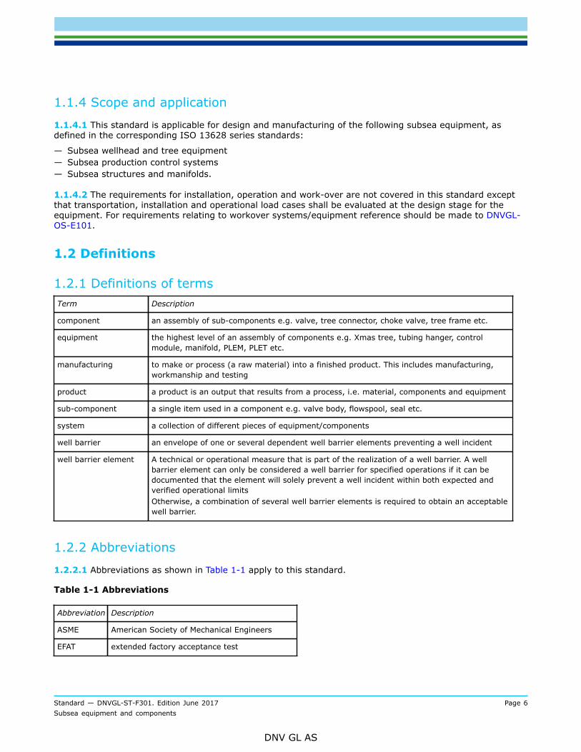
1.1.4 Scope and application
1.1.4.1 This standard is applicable for design and manufacturing of the following subsea equipment, asdefined in the corresponding ISO 13628 series standards:
— Subsea wellhead and tree equipment— Subsea production control systems— Subsea structures and manifolds.
1.1.4.2 The requirements for installation, operation and work-over are not covered in this standard exceptthat transportation, installation and operational load cases shall be evaluated at the design stage for theequipment. For requirements relating to workover systems/equipment reference should be made to DNVGL-OS-E101.
1.2 Definitions
1.2.1 Definitions of termsTerm Description
component an assembly of sub-components e.g. valve, tree connector, choke valve, tree frame etc.
equipment the highest level of an assembly of components e.g. Xmas tree, tubing hanger, controlmodule, manifold, PLEM, PLET etc.
manufacturing to make or process (a raw material) into a finished product. This includes manufacturing,workmanship and testing
product a product is an output that results from a process, i.e. material, components and equipment
sub-component a single item used in a component e.g. valve body, flowspool, seal etc.
system a collection of different pieces of equipment/components
well barrier an envelope of one or several dependent well barrier elements preventing a well incident
well barrier element A technical or operational measure that is part of the realization of a well barrier. A wellbarrier element can only be considered a well barrier for specified operations if it can bedocumented that the element will solely prevent a well incident within both expected andverified operational limitsOtherwise, a combination of several well barrier elements is required to obtain an acceptablewell barrier.
1.2.2 Abbreviations
1.2.2.1 Abbreviations as shown in Table 1-1 apply to this standard.
Table 1-1 Abbreviations
Abbreviation Description
ASME American Society of Mechanical Engineers
EFAT extended factory acceptance test
Standard — DNVGL-ST-F301. Edition June 2017 Page 7Subsea equipment and components
DNV GL AS
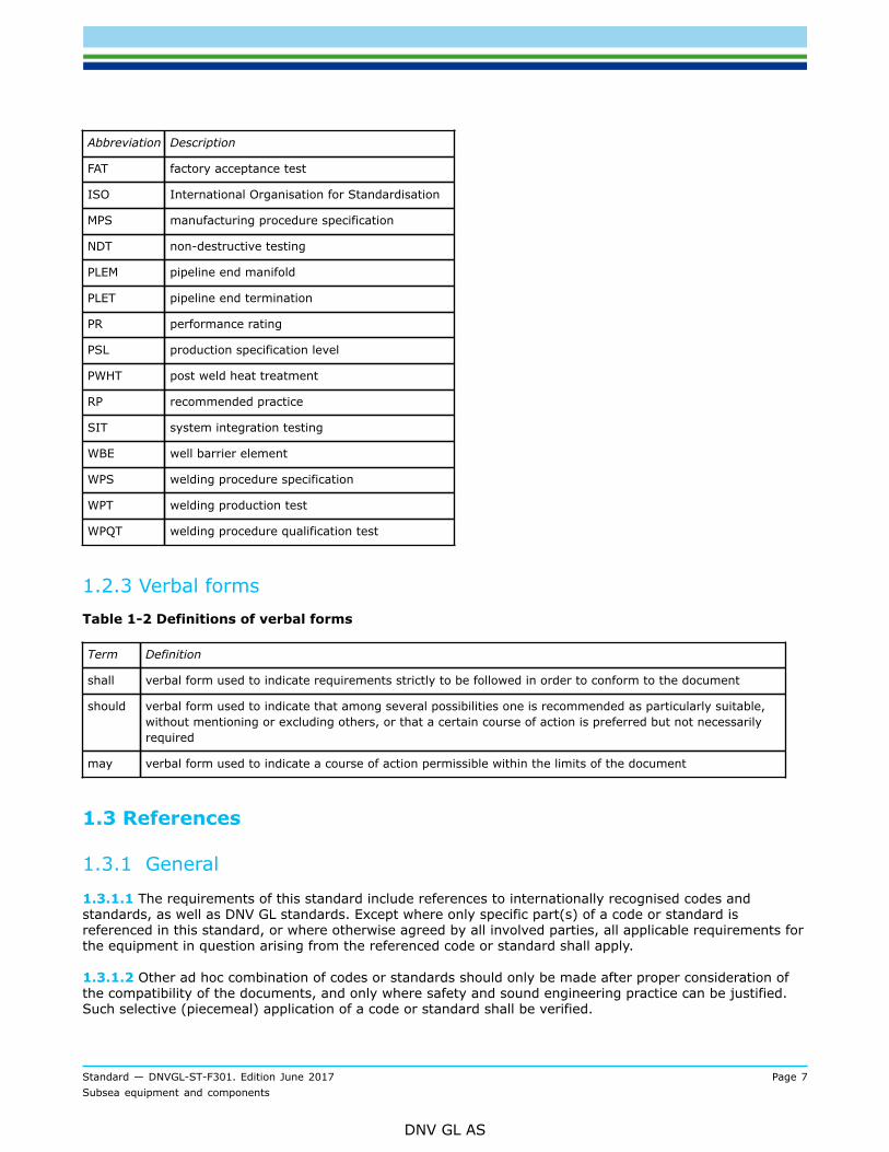
Abbreviation Description
FAT factory acceptance test
ISO International Organisation for Standardisation
MPS manufacturing procedure specification
NDT non-destructive testing
PLEM pipeline end manifold
PLET pipeline end termination
PR performance rating
PSL production specification level
PWHT post weld heat treatment
RP recommended practice
SIT system integration testing
WBE well barrier element
WPS welding procedure specification
WPT welding production test
WPQT welding procedure qualification test
1.2.3 Verbal formsTable 1-2 Definitions of verbal forms
Term Definition
shall verbal form used to indicate requirements strictly to be followed in order to conform to the document
should verbal form used to indicate that among several possibilities one is recommended as particularly suitable,without mentioning or excluding others, or that a certain course of action is preferred but not necessarilyrequired
may verbal form used to indicate a course of action permissible within the limits of the document
1.3 References
1.3.1 General
1.3.1.1 The requirements of this standard include references to internationally recognised codes andstandards, as well as DNV GL standards. Except where only specific part(s) of a code or standard isreferenced in this standard, or where otherwise agreed by all involved parties, all applicable requirements forthe equipment in question arising from the referenced code or standard shall apply.
1.3.1.2 Other ad hoc combination of codes or standards should only be made after proper consideration ofthe compatibility of the documents, and only where safety and sound engineering practice can be justified.Such selective (piecemeal) application of a code or standard shall be verified.
Standard — DNVGL-ST-F301. Edition June 2017 Page 8Subsea equipment and components
DNV GL AS
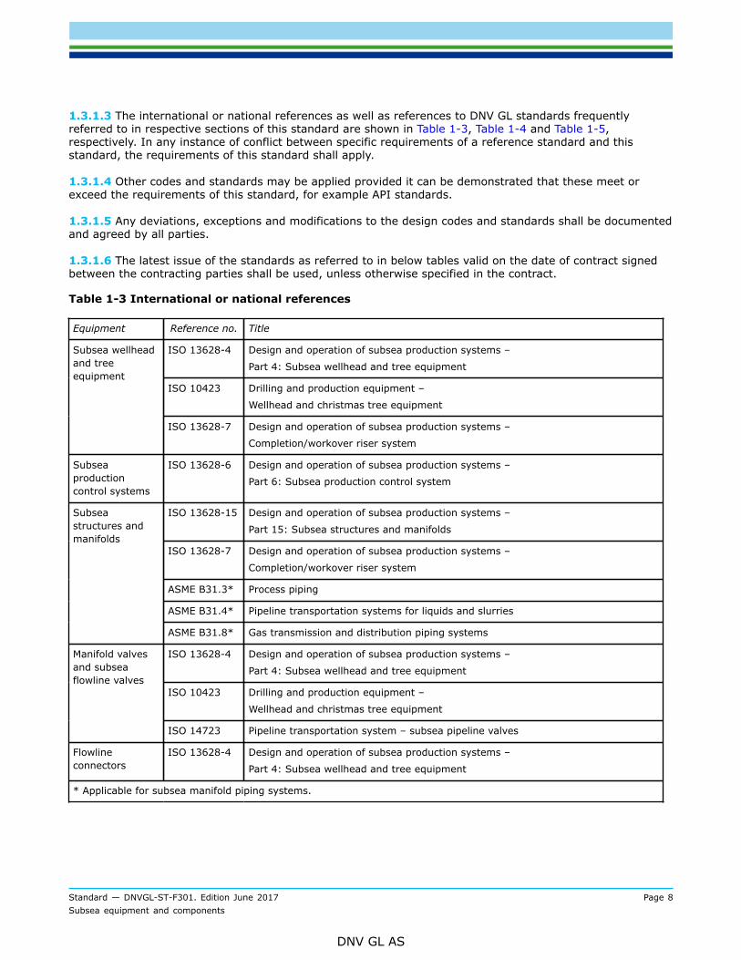
1.3.1.3 The international or national references as well as references to DNV GL standards frequentlyreferred to in respective sections of this standard are shown in Table 1-3, Table 1-4 and Table 1-5,respectively. In any instance of conflict between specific requirements of a reference standard and thisstandard, the requirements of this standard shall apply.
1.3.1.4 Other codes and standards may be applied provided it can be demonstrated that these meet orexceed the requirements of this standard, for example API standards.
1.3.1.5 Any deviations, exceptions and modifications to the design codes and standards shall be documentedand agreed by all parties.
1.3.1.6 The latest issue of the standards as referred to in below tables valid on the date of contract signedbetween the contracting parties shall be used, unless otherwise specified in the contract.
Table 1-3 International or national references
Equipment Reference no. Title
ISO 13628-4 Design and operation of subsea production systems –
Part 4: Subsea wellhead and tree equipment
ISO 10423 Drilling and production equipment –
Wellhead and christmas tree equipment
Subsea wellheadand treeequipment
ISO 13628-7 Design and operation of subsea production systems –
Completion/workover riser system
Subseaproductioncontrol systems
ISO 13628-6 Design and operation of subsea production systems –
Part 6: Subsea production control system
ISO 13628-15 Design and operation of subsea production systems –
Part 15: Subsea structures and manifolds
ISO 13628-7 Design and operation of subsea production systems –
Completion/workover riser system
ASME B31.3* Process piping
ASME B31.4* Pipeline transportation systems for liquids and slurries
Subseastructures andmanifolds
ASME B31.8* Gas transmission and distribution piping systems
ISO 13628-4 Design and operation of subsea production systems –
Part 4: Subsea wellhead and tree equipment
ISO 10423 Drilling and production equipment –
Wellhead and christmas tree equipment
Manifold valvesand subseaflowline valves
ISO 14723 Pipeline transportation system – subsea pipeline valves
Flowlineconnectors
ISO 13628-4 Design and operation of subsea production systems –
Part 4: Subsea wellhead and tree equipment
* Applicable for subsea manifold piping systems.
Standard — DNVGL-ST-F301. Edition June 2017 Page 9Subsea equipment and components
DNV GL AS
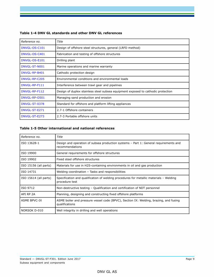
Table 1-4 DNV GL standards and other DNV GL references
Reference no. Title
DNVGL-OS-C101 Design of offshore steel structures, general (LRFD method)
DNVGL-OS-C401 Fabrication and testing of offshore structures
DNVGL-OS-E101 Drilling plant
DNVGL-ST-N001 Marine operations and marine warranty
DNVGL-RP-B401 Cathodic protection design
DNVGL-RP-C205 Environmental conditions and environmental loads
DNVGL-RP-F111 Interference between trawl gear and pipelines
DNVGL-RP-F112 Design of duplex stainless steel subsea equipment exposed to cathodic protection
DNVGL-RP-O501 Managing sand production and erosion
DNVGL-ST-0378 Standard for offshore and platform lifting appliances
DNVGL-ST-E271 2.7-1 Offshore containers
DNVGL-ST-E273 2.7-3 Portable offshore units
Table 1-5 Other international and national references
Reference no. Title
ISO 13628-1 Design and operation of subsea production systems – Part 1: General requirements andrecommendations
ISO 19900 General requirements for offshore structures
ISO 19902 Fixed steel offshore structures
ISO 15156 (all parts) Materials for use in H2S-containing environments in oil and gas production
ISO 14731 Welding coordination – Tasks and responsibilities
ISO 15614 (all parts) Specification and qualification of welding procedures for metallic materials – Weldingprocedure test
ISO 9712 Non-destructive testing – Qualification and certification of NDT personnel
API RP 2A Planning, designing and constructing fixed offshore platforms
ASME BPVC-IX ASME boiler and pressure vessel code (BPVC), Section IX: Welding, brazing, and fusingqualifications
NORSOK D-010 Well integrity in drilling and well operations
Standard — DNVGL-ST-F301. Edition June 2017 Page 10Subsea equipment and components
DNV GL AS
SECTION 2 DESIGN PRINCIPLES
2.1 General
2.1.1 Scope and application
2.1.1.1 Subsea equipment shall, as a minimum, be designed in accordance with one of the recognised codesand standards listed in [1.3.1] and in accordance with the additional requirements specified in this standard.
2.1.1.2 The requirements of this section apply to subsea equipment listed in [1.1.4.1], whose failure has thepotential to adversely affect the safety or integrity of the subsea production system.
2.1.1.3 The principles stated in this section shall be adhered to in implementing requirements outlinedelsewhere in this standard.
2.2 Well barrier
2.2.1 General
2.2.1.1 Subsea equipment shall be designed and tested so as to reduce risk of uncontrolled release offormation fluids throughout its life cycle.
2.2.1.2 Well barriers in accordance with NORSOK D-010 shall be defined.
2.2.1.3 Well barrier elements (WBE’s), their acceptance criteria, their use and monitoring of their integrityduring their life cycle shall be defined.
2.2.1.4 The end-user shall be provided with all relevant information developed during design pertaining tothe safe use and operation of the equipment throughout its life cycle, e.g. an operations and maintenancemanual.
2.3 Design conditions
2.3.1 General
2.3.1.1 A minimum of product specification level (PSL) 3, in accordance with that defined in ISO 10423, shallapply to the subsea equipment covered by this standard. For equipment which are not required to specify aPSL level, equivalent quality shall be maintained.
2.3.1.2 Where gas service is expected at any point during the life-cycle of the component, PSL 3G, inaccordance with that defined in ISO 10423, shall apply to the subsea equipment.
2.3.1.3 Equipment shall be designed to operate for the required pressure/temperature cycles, cyclic externalloads and multiple make/break (latch/unlatch), as applicable and where applicable as verified in validationtesting.
2.3.1.4 Equipment with materials covered by DNVGL-RP-F112 shall be designed in accordance with thestated acceptance criteria for stress and strain in addition to the basic design code.
Standard — DNVGL-ST-F301. Edition June 2017 Page 11Subsea equipment and components
DNV GL AS
2.3.1.5 Service conditions for the subsea tree components shall be consistent with the service conditionsspecified for the subsea tree system.
2.3.1.6 The design pressure of subsea equipment shall not be less than the pressure at the most severecondition of coincident internal or external pressure and temperature (minimum or maximum) expectedduring service.
2.3.1.7 Process conditions which may result in impulse loading, such as surge, water hammer and two-phase flow, shall be evaluated.
2.3.1.8 Thermal effects caused by internal fluid and external environment shall be determined for allsubsea equipment. Equipment shall then be designed to the specified temperature ratings with the exposedminimum and maximum temperatures.
Guidance note:Thermal analyses is important for sealing systems and valve internals to verify robustness in design and for the design of thecathodic protection system.
---e-n-d---o-f---g-u-i-d-a-n-c-e---n-o-t-e---
2.3.1.9 Seal designs shall take external hydrostatic pressure into account where reverse pressure acting onthe seal due to external hydrostatic pressure exceeds internal bore pressure. All operating conditions (i.e.commissioning, testing, start-up, operation, blowdown) shall be evaluated.
2.3.1.10 Primary structural components, such as guidebases, tree frames, protection structures etc. shallbe designed in accordance with accepted industry practices such as ISO 19900, 19902, DNVGL-OS-C101 andAPI RP 2A.
2.4 Design loads
2.4.1 General
2.4.1.1 Environmental phenomena that might impair proper functioning of the system or cause a reductionof the integrity and safety of the system shall be evaluated. Recommended practice for principles andmethodologies for establishing environmental conditions and loads is given in DNVGL-RP-C205.
2.4.1.2 The most unfavourable load scenario for all relevant phases and conditions which may influence thesubsea equipment integrity and safety shall be evaluated as required by applicable and recognised standards.
2.4.1.3 Equipment design shall be capable of sustaining rated loads without deformation to such an extentthat prevents meeting any other performance requirement, providing stress criteria are not exceeded. Thesecriteria shall be in accordance with ISO 13628-7.
2.4.1.4 Loads to be covered in the design for the life cycle of subsea equipment are as follows:
— operation loads— accidental loads— pressure testing loads (onshore and offshore)— load-out and transportation loads— installation loads— intervention loads— retrieval loads.
Standard — DNVGL-ST-F301. Edition June 2017 Page 12Subsea equipment and components
DNV GL AS
2.4.2 Operational loads
2.4.2.1 Operation loads cover the following typical loads for pressure containing and retaining equipment:
— sustained loads (e.g. design pressure, permanent loads, weight and buoyancy)— displacement Loads (e.g. thermal expansion/contraction, structural deflections on supports, external
imposed deflections)— environmental loads (e.g. earthquake, current, wave, water depth).
2.4.2.2 If the code or standard used for design of a component does not take into account the possibilityfor internal leakage due to forces transferred to the component from the connecting sections, the additionalcalculations and/or qualification tests shall be performed. External flowline and jumper loads shall beincluded in the component design.
2.4.2.3 Environmental loads are defined as those loads on subsea equipment which are caused by thesurrounding environment. Recommended practice for calculation of characteristic environmental loads isgiven in DNVGL-RP-C205.
2.4.2.4 Casing hangers shall be locked down to ensure seal integrity during normal operational loads as wellas well control situations.
2.4.3 Accidental loads
2.4.3.1 Loads which are imposed on subsea equipment under abnormal and unplanned conditions and withan annual probability of occurrence less than 10-2 shall be classified as accidental loads. Typical accidentalloads can be caused by:
— dropped objects— dragging anchors— infrequent internal over pressure (e.g. in case of malfunction of HIPPS)— seabed movement and/or mud slides (earthquake)— operational malfunction— ROV impact loads— ROV umbilical snag loads.
2.4.3.2 Dropped object and fishing gear loads shall be in accordance with ISO 13628-1 annex F5.
2.4.3.3 Recommended practice for calculations of trawl interference loads is given in DNVGL-RP-F111.
2.4.4 Pressure testing loads
2.4.4.1 Pressure contained equipment will be pressure tested and its effect, such as stress, support loadsand loads on to sensitive component must be checked.
2.4.4.2 In-service pressure testing loads shall also be evaluated in the design.
2.4.5 Load-out and transportation loads
2.4.5.1 During load-out the equipment structure will be lifted. The imposed deflections at anchor/supportsfrom the structure shall be evaluated in addition to dry weight and weight of any contained test fluid.
Standard — DNVGL-ST-F301. Edition June 2017 Page 13Subsea equipment and components
DNV GL AS
2.4.5.2 Lifting analysis shall be performed according to DNVGL-ST-N001 Marine operations and marinewarranty, DNVGL-ST-0378 Standard for offshore and platform lifting appliances or DNVGL-ST-E273 2.7-3Portable offshore units. as applicable.
2.4.5.3 Arrangements for sea transport shall be designed and tested in accordance with DNVGL-ST-N001and DNVGL-ST-0378.
2.4.5.4 Where test stands and fixtures are to be used on an object (mobile offshore unit, ship or offshoreinstallation) then those test stands and fixtures shall be designed with consideration given to the dynamicmovement of the intended object. It should be noted that these loads may be different to the transit/survivalconditions specified for transportation at sea.
2.4.6 Installation loads
2.4.6.1 The design and analysis of subsea equipment shall evaluate the installation effect. The installationcovers the following possible phases/stages:
— lifting in air— lowering through splash zone (wave slamming forces)— lowering towards seabed— pull-in and connection with other components, such as flowlines/spools— installation of other components— external water pressure.
2.4.6.2 Installation lift analyses of the structures shall be performed according to DNVGL-ST-N001 or DNVGL standards for certification as applicable.
2.4.7 Intervention loads
2.4.7.1 Intervention loads are loads associated with planned and unplanned well interventions, typicallyfrom:
— riser based workover operations— wireline operations— coiled tubing operations.
2.4.7.2 The intervention strategy for the well shall be planned for at the design stage of the equipment.
2.4.8 Retrieval loads
2.4.8.1 Retrieval of subsea equipment may occur. The retrieval process is normally covered by theinstallation case in reverse order.
2.4.8.2 Additional and possible excessive loads due to marine growth or mechanisms preventing easydetachment of connecting surfaces, resulting in potential recoil effects, shall be evaluated.
2.4.8.3 Suitable lifting arrangement should be designed to sustain throughout the operational life of thestructure.
Standard — DNVGL-ST-F301. Edition June 2017 Page 14Subsea equipment and components
DNV GL AS
2.5 Design documentation
2.5.1 General
2.5.1.1 The design documentation shall follow the requirements in the applicable recognised standards.
2.6 Material selection and corrosion consideration
2.6.1 General
2.6.1.1 Materials shall be robust and suitable for the purpose, and shall have adequate properties regardingstrength, notch toughness, and ductility. In addition, materials to be welded shall have good weldabilityproperties.
2.6.1.2 Suitable allowances shall be included for possible degradation of the mechanical properties resultingfrom subsequent fabrication and installation activities e.g. from corrosion, thermal effects or ageing ofmaterials.
2.6.1.3 Materials shall have adequate corrosion resistance or a corrosion protective system such as coatings,cathodic protection, or chemical treatment of corrosive fluids.
Guidance note:The corrosion control program should be defined by the end user to ensure that no unexpected intervention is required – sofor example the cathodic protection calculations should be based on an anticipated worst case scenario to avoid unnecessaryinterventions in the latter stages of the field life.
---e-n-d---o-f---g-u-i-d-a-n-c-e---n-o-t-e---
2.6.1.4 DNVGL-RP-B401 shall be used as the primary reference for cathodic protection systems. The statedrecommendations for calculation parameters are mandatory (e.g. 2000 Ahr/kg for electrochemical capacity).
2.6.1.5 The selection of materials and/or corrosion protective systems shall ensure compatibility, takinginto account the effect of relevant operational parameters, techniques for inspection, monitoring andmaintenance, and the required design life.
2.6.1.6 Equipment with materials covered by DNVGL-RP-F112 shall be identified and the delivery conditionshall be specified. Special design considerations shall be performed. See [2.3.1.4].
2.6.1.7 Dissimilar metallic materials in contact shall be avoided or adequately protected against galvaniccorrosion.
2.6.1.8 Precautions shall be taken to monitor and avoid erosion in subsea equipment, reference is made toDNVGL-RP-O501.
2.6.1.9 All equipment and components shall be free from asbestos.

Standard — DNVGL-ST-F301. Edition June 2017 Page 15Subsea equipment and components
DNV GL AS
2.7 Written material specifications and certificates
2.7.1 Written material specifications
2.7.1.1 A written material specification for pressure-containing and pressure-retaining equipment shall beestablished. This specification shall clearly identify all manufacturing and testing requirements.
2.7.1.2 Written material specifications shall be in accordance with the applicable codes and standardsapplied to the subsea equipment.
2.7.1.3 Pre-qualification of materials based on loads, temperatures and service conditions shall beconsidered in order to verify that the materials will fulfil functional requirements.
2.7.2 Material certificates
2.7.2.1 All materials for pressure-containing and pressure-retaining equipment, primary load-bearing andload carrying parts shall be supplied with certificates stating process of manufacture and heat treatment(metallic materials) together with test results for all specified tests and inspections.
2.7.2.2 Material certificates shall make reference to the material specifications, see [2.7.1].
Standard — DNVGL-ST-F301. Edition June 2017 Page 16Subsea equipment and components
DNV GL AS
SECTION 3 MANUFACTURE, WORKMANSHIP AND TESTING
3.1 General
3.1.1 Scope and application
3.1.1.1 Subsea equipment shall, as a minimum, be manufactured in accordance with one of the recognisedcodes and standards listed in [1.3.1] and in accordance with the additional requirements specified in thisstandard.
3.1.1.2 The requirements of this apply to subsea equipment listed in [1.1.4.1], whose failure has thepotential to adversely affect the safety or integrity of the subsea production system.
3.1.1.3 The principles stated in this section shall be adhered to in implementing requirements outlinedelsewhere in this standard.
3.1.2 Quality assurance and quality control
3.1.2.1 All manufacturing, quality control, testing and manufacturing record requirements relating to theselected PSL stipulated in the referenced codes and standards shall apply. For equipment which it is notrequired to specify a PSL, equivalent quality control, testing and manufacturing records shall be maintained.
3.1.2.2 The manufacturer shall utilise the necessary production facilities, qualifications, procedures, andpersonnel to ensure that the product will be manufactured to the specified requirements.
3.1.2.3 Quality control testing shall be performed in accordance with a test specification which clearlydefines both the testing method and acceptance criteria.
3.1.3 Marking
3.1.3.1 All equipment shall be clearly marked with identification and serial number which relates theequipment to certificates and manufacture documentation.
3.2 Manufacture
3.2.1 General
3.2.1.1 Manufacturing shall be performed according to a manufacturing procedure specification (MPS)prepared by the manufacturer. The MPS shall describe how the specified properties may be achieved andverified through the proposed manufacturing route.
3.2.1.2 The use of calibrated torque or bolt-tensioning equipment is required to ensure accurate make-uptension. The torqueing and tensioning procedure shall be documented.
3.2.2 Qualification of welders and welding coordinators
3.2.2.1 All personnel involved in welding related tasks shall have adequate qualifications and understandingof welding technology. The qualification level shall reflect the tasks and responsibilities of each person inorder to obtain the required quality level.

Standard — DNVGL-ST-F301. Edition June 2017 Page 17Subsea equipment and components
DNV GL AS
3.2.2.2 The organization responsible for welding shall nominate at least one authorized welding co-ordinatorin accordance with ISO 14731 to be present at the location where welding is performed. The welding co-ordinator shall have comprehensive technical knowledge according to ISO 14731, paragraph 6.2.a.
3.2.2.3 Qualification of welders shall be in accordance with DNVGL-OS-C401 or the applied code.Guidance note:Welders qualified to another code than the design code may be suitable provided that the design code is demonstrated to besuitable and relevant qualifications are documented.
---e-n-d---o-f---g-u-i-d-a-n-c-e---n-o-t-e---
3.2.2.4 The manufacturer shall supply each welder with an identification number or symbol to enableidentification of the work carried out by each particular welder.
3.2.3 Welding
3.2.3.1 All welding shall be performed in accordance with a qualified welding procedure specification (WPS)which shall be documented on a welding procedure qualification record (WPQR).
3.2.3.2 A welding procedure qualification test (WPQT) shall be performed when applying a WPS for whichthere is insufficient experience at the plant or elsewhere, or where applied to new complicated structuraldetails. The extent of the procedure test shall be agreed before the work is started and shall be performed inaccordance with a recognised standard (ISO 15614/ASME IX).
Guidance note:Fabrication welding production test (WPT) should be provided where it is recommended to verify that the produced welds are ofacceptable quality, e.g.
— When the WPQR/WPS have not been used for the last 3 years.
— The contractor has limited previous experience with the welding equipment and welding methods used.
— The welds are defined as critical with respect to key parameters such as carbon equivalent, hardness, impact values orstrength. The critical parameters must be defined by the project. If any deviation to essential variables of WPS duringproduction welding.
— Increased quality measures due to large number of welds, if severe defects occur repeatedly, at risk of errors or criticalacceptance criteria or any other incident indicating inadequate welding performance.
— The welding inspection performed is found to be inadequate.
— During fabrication of welds in special areas and for primary structural elements to verify that the produced welds are ofacceptable quality.
The extent and type of testing should be the same as for the relevant WPQT, or consistent with the requirements of the project.The test assembly and test requirements should comply with the relevant requirements of the project or reference standard.
---e-n-d---o-f---g-u-i-d-a-n-c-e---n-o-t-e---
3.2.3.3 If supports and similar non-pressure parts are welded directly to pressure containing parts, thewelding requirements for the pressure retaining parts shall be applied. Doubler plates in the same material asthe base material shall be used when welding supports or similar to the pressure containing parts.
3.2.3.4 Welding repairs, if permitted by applicable codes, shall be performed according to a qualified repairprocedure.
3.2.4 Heat treatment
3.2.4.1 After forming/bending and/or welding, the component shall be heat treated if required according tothe applied code or standard, or if found necessary to maintain adequate mechanical properties.
Standard — DNVGL-ST-F301. Edition June 2017 Page 18Subsea equipment and components
DNV GL AS
3.2.4.2 Heat treatment documentation shall include heat treatment temperature, heating and coolingparameters, heat treatment time at temperature and cooling media.
3.2.4.3 A normalising heat treatment shall be applied for hot formed parts, unless the process of hot forminghas been carried out within the appropriate temperature range, duration, and cooling rate.
3.2.4.4 The heat treatment for cold worked materials shall be selected with respect to the degree of plasticdeformation in the material.
3.2.4.5 Preheating and/or post weld heat treatment shall be used when necessitated by the dimensions andmaterial composition.
3.2.4.6 Post weld heat treatment (PWHT) shall normally be performed in a fully enclosed furnace. LocalPWHT may be performed on simple joints when following a qualified procedure.
3.2.4.7 The maximum PWHT temperature for quenched and tempered low alloy steel shall be 25°C less thanthe tempering temperature of the material as stated in the material certificate.
3.2.4.8 In the case of defects revealed after heat treatment, new heat treatment shall normally beperformed after repair welding of the defects.
3.2.4.9 Multiple PWHT shall be qualified to verify that the material properties after such treatment remainwithin the specified limits.
3.2.5 Pipe bending
3.2.5.1 The bending procedure shall be such that the flattening of the pipe cross section and wall thinningare within acceptable tolerances specified in the applied code and standard.
3.2.5.2 The bending procedure shall be qualified to ensure that the required mechanical properties afterbending, with or without post bend heat treatment, are maintained.
3.3 Testing
3.3.1 Non-destructive testing
3.3.1.1 Non-destructive testing (NDT) procedures, extent and acceptance criteria shall be according torelevant codes, standards, or other independently agreed specifications.
3.3.1.2 NDT shall be carried out by operators qualified to a certification scheme, such as ISO 9712 orequivalent.
3.3.1.3 When post weld heat treatment is required, final NDT shall be performed after heat treatment.
3.3.1.4 The final NDT shall be performed prior to any possible process which would make the required NDTimpossible, or which could cause erroneous results (e.g. coating of surfaces).
3.3.1.5 If the NDT examination reveals a defect requiring repair, additional testing shall be carried out inaccordance with the applied code or standard, unless otherwise justified.
3.3.1.6 All performed examination and results shall be systematically recorded and fully traceable.
Standard — DNVGL-ST-F301. Edition June 2017 Page 19Subsea equipment and components
DNV GL AS
3.3.2 Validation testing
3.3.2.1 Performance rating PR2, in accordance with that defined in ISO 10423, shall apply to the subseaequipment designed according to this standard.
3.3.2.2 Validation testing shall, as a minimum, be in accordance with the requirements of the referencecodes and standards. Additionally, for subsea tree and wellhead equipment ISO 13628-4 Annex L (hyperbarictesting guidelines) is mandatory.
3.3.2.3 Where the endurance testing requirement in accordance with ISO13628-4 Table 3 is stated as permanufacturers rating, the endurance testing shall be performed to demonstrate the equipment’s suitabilityfor its intended service.
Guidance note:For example a running tool which requires major inspection after 100 uses should be tested for a minimum of 100 uses.
---e-n-d---o-f---g-u-i-d-a-n-c-e---n-o-t-e---
3.3.2.4 It shall be possible to verify by direct examination of the records of validation testing that theproduct is properly qualified.
3.3.2.5 Dimensional information shall be reported before and after validation testing with methods sensitiveenough to detect the extent of permanent deformation expected.
3.3.2.6 The component shall be disassembled and inspected to identify any damages and deformations thatwill affect the operation.
3.3.3 Factory acceptance testing
3.3.3.1 Factory acceptance test (FAT) covers testing of individual equipment and component assemblies.Testing of several equipment assemblies are commonly referred to as extended factory acceptance test(EFAT).
3.3.3.2 All equipment, including associated control, monitoring and safety systems shall be tested as far aspossible prior to installation.
3.3.3.3 Equipment shall be function tested under working conditions in accordance with written testprocedures. Testing of all safety functions shall be included.
3.3.3.4 Tests shall as a minimum include adjustment of controllers, calibration of sensors and alarms,function testing of normal and safety systems etc. Test control units shall be used to simulate the subseaoperation.
3.3.3.5 The status of tests shall be recorded in an auditable manner and a system to control status ofremedial and outstanding work shall be established.
3.3.3.6 Where valves on the production system are intended to function as emergency shutdown valves,the closure time of those valves shall be measured and recorded during factory acceptance testing. This testrequires that the valve is tested with the relevant parts of the control system.
3.3.3.7 All pressure testing shall be recorded on a chart recorder for documentation purposes. The chartrecord shall have an acceptable pressure settling rate not exceeding 3% of the test pressure per hour. Thefinal settling pressure shall not fall below the test pressure before the end of the test hold period. Initial testpressure shall not be more than 5% greater the specified test pressure. No leakage is acceptable and thepressure stabilization shall be related to temperature fluctuations.
Standard — DNVGL-ST-F301. Edition June 2017 Page 20Subsea equipment and components
DNV GL AS
Guidance note:Pressure testing of piping systems may include a more stringent requirement for pressure settling rate than 3%. Additionalrequirements concerning pressure settling rate and holding period may be specified by the project.
---e-n-d---o-f---g-u-i-d-a-n-c-e---n-o-t-e---
3.3.3.8 Electric continuity tests shall be performed to prove the electrical contact between parts of thecathodic protection system. Installation and testing of the cathodic protection system shall be in accordancewith DNVGL-RP-B401.
3.3.4 System integration testing
3.3.4.1 System integration testing (SIT) is outside the scope of this standard. The SIT normally includes theSPS, consisting of XT system, control system, manifold and tie-in systems. In addition, flowline and umbilicalinterfaces are tested.
3.3.4.2 It is assumed that SIT activities shall be performed on each production unit to validate the correctinterface/operation of the equipment prior to installation.
Cha
nges
– h
isto
ric
Standard — DNVGL-ST-F301. Edition June 2017 Page 21Subsea equipment and components
DNV GL AS
CHANGES – HISTORICThere are currently no historical changes for this document.

About DNV GLDriven by our purpose of safeguarding life, property and the environment, DNV GL enablesorganizations to advance the safety and sustainability of their business. We provide classification,technical assurance, software and independent expert advisory services to the maritime, oil & gasand energy industries. We also provide certification services to customers across a wide rangeof industries. Operating in more than 100 countries, our experts are dedicated to helping ourcustomers make the world safer, smarter and greener.
SAFER, SMARTER, GREENER