DNVGL-ST-0068 Certification of container securing...
23
The electronic pdf version of this document, available free of charge from http://www.dnvgl.com, is the officially binding version. DNV GL AS STANDARD DNVGL-ST-0068 Edition May 2016 Certification of container securing devices
Transcript of DNVGL-ST-0068 Certification of container securing...
The electronic pdf version of this document, available free of chargefrom http://www.dnvgl.com, is the officially binding version.
DNV GL AS
STANDARD
DNVGL-ST-0068 Edition May 2016
Certification of container securing devices

FOREWORD
DNV GL standards contain requirements, principles and acceptance criteria for objects, personnel,organisations and/or operations.
© DNV GL AS May 2016
Any comments may be sent by e-mail to [email protected]
This service document has been prepared based on available knowledge, technology and/or information at the time of issuance of thisdocument. The use of this document by others than DNV GL is at the user's sole risk. DNV GL does not accept any liability or responsibilityfor loss or damages resulting from any use of this document.

Cha
nges
- c
urre
nt
Standard — DNVGL-ST-0068. Edition May 2016 Page 3Certification of container securing devices
DNV GL AS
CHANGES – CURRENT
This is a new document.
Con
tent
s
Standard — DNVGL-ST-0068. Edition May 2016 Page 4Certification of container securing devices
DNV GL AS
CONTENTS
Changes – current.................................................................................................. 3
Section 1 General....................................................................................................51.1 Objective...........................................................................................51.2 Application........................................................................................51.3 Scope................................................................................................ 51.4 Definitions.........................................................................................51.5 Documentation..................................................................................5
Section 2 Certification.............................................................................................72.1 General............................................................................................. 72.2 Certification procedure..................................................................... 7
Section 3 Materials and welding............................................................................. 83.1 General............................................................................................. 83.2 Container support fittings.................................................................83.3 Container securing equipment.......................................................... 83.4 Heat treatment................................................................................. 93.5 Mechanical tests............................................................................... 9
Section 4 Type approval........................................................................................114.1 General........................................................................................... 114.2 Plan approval..................................................................................114.3 Prototype testing............................................................................ 144.4 Operational testing of fully automatic locks................................... 15
Section 5 Case-by-case approval...........................................................................195.1 ....................................................................................................... 19
Section 6 Production testing................................................................................. 206.1 General........................................................................................... 20
Section 7 Marking................................................................................................. 217.1 ....................................................................................................... 21
Changes – historic................................................................................................22

Standard — DNVGL-ST-0068. Edition May 2016 Page 5Certification of container securing devices
DNV GL AS
SECTION 1 GENERAL
1.1 ObjectiveThis standard intends to guide through the certification process for container securing devices.
1.2 ApplicationThe requirements in this document are supplementary to those given in RU SHIP Pt.5 Ch.2 Sec.8. They applyto container support fittings and container securing equipment. Additionally, they apply to fixed securingpoints and Society's certified portable securing devices used for lashing of vehicles, in accordance with therequirement given in the rules RU SHIP Pt.5 Ch.3 Sec.1 [5.1].
1.3 ScopeThis document describes the procedures and requirements for obtaining product certificates for securingdevices.The following topics are covered:
— materials and welding— type approval— prototype testing— production testing— marking.
1.4 DefinitionsFor definitions not defined in this document, see RU SHIP Pt.5 Ch.2 Sec.1 [1.5].
Table 1-1 Definitions
Term Definition
lashing a system for securing of containers using non-rigid devices such as lashingrods and turnbuckles, or a securing device used in a lashing system, e.g. alashing rod
safe working load, SWL the allowable load capacity for a device used to secure cargo to a ship
minimum breaking load, BL the tested minimum breaking load of a container securing device
safety factor, S = BL / SWL
usage factor, η = SWL / BL i.e. the inverse of safety factor
proof load, PL the test load during testing of container securing devices
prototype an equipment item considered to be representative for the production andthe product to be approved, used for prototype testing. The prototype mayeither be manufactured specially for type testing or selected at randomfrom a production series. If manufactured specially, it is assumed thatthe tools and the production process are comparable to those used forsubsequent production.

Standard — DNVGL-ST-0068. Edition May 2016 Page 6Certification of container securing devices
DNV GL AS
1.5 DocumentationDocumentation shall be submitted as per Table 1-2 and, if relevant, per Table 1-3.
Table 1-2 Documentation requirements
Object Documentation type Additional description Info
C030 – Detail drawing Including SWL, BL and PL AP
M010 – Material specification,metals AP
Securing device
Z130 – Report from test atmanufacturer
Prototype test report endorsed by a Society'ssurveyor, including:
— description of test arrangement— applied loads— results— SWL, BL and PL.
FI
Table 1-3 Additional documentation requirements for fully automatic locks
Object Documentation type Additional description Info
Fully automaticlocks
Z130 – Report from test at testlaboratory agreed by the Society
Operational test report issued by themanufacturer and endorsed by the Society,including:
— description of test arrangement— applied loads— results.
FI
For general requirements to documentation, see RU SHIP Pt.1 Ch.3 Sec.2.For a full definition of documentation types, see RU SHIP Pt.1 Ch.3 Sec.3.
Standard — DNVGL-ST-0068. Edition May 2016 Page 7Certification of container securing devices
DNV GL AS
SECTION 2 CERTIFICATION
2.1 GeneralAccording to the rules RU SHIP Pt.5 Ch.2 Sec.8 [2.2], all container securing devices, shall be deliveredwith product certificates. Product certificates are in general issued based on material certification, designapproval, prototype testing and production testing. Design approval may be either type approval or case-by-case approval upon special agreement, i.e. an approval which is only valid for a single delivery. The variousapproval and test schemes are described in detail in the following sections.
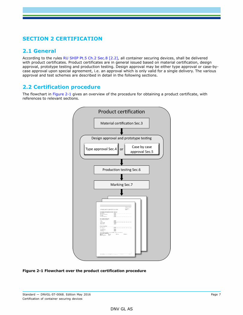
2.2 Certification procedureThe flowchart in Figure 2-1 gives an overview of the procedure for obtaining a product certificate, withreferences to relevant sections.
Figure 2-1 Flowchart over the product certification procedure

Standard — DNVGL-ST-0068. Edition May 2016 Page 8Certification of container securing devices
DNV GL AS
SECTION 3 MATERIALS AND WELDING
3.1 GeneralContainer support fittings shall be delivered with Society's material certificates. Container securingequipment shall be delivered with works material certificates from the manufacturer, e.g. an acceptance testcertificate 3.1 as to EN 10204.
3.2 Container support fittings
3.2.1 Container support fittings intended for welding into the hull structure shall be made of forged or cast carbonor carbon-manganese steels, or shall be cut from rolled materials of normal or high-strength hull structuralsteel.The materials shall comply with relevant chapters and sections of RU SHIP Pt.2 and the additionalrequirements given in this subsection.
3.2.2 The carbon content of cast and forged steel shall not exceed 0.23%.
3.2.3 Specified minimum yield stress for castings and forgings shall not exceed 400 N/mm2.
3.3 Container securing equipment
3.3.1 Container securing equipment shall be made of forged or cast steel or machined from rolled material. Thematerials shall comply with a recognised national or international standard and the additional requirementsgiven in this subsection. Specifications deviating from the requirements given herein may be evaluated onthe basis of documented experience or comprehensive test results.Materials shall only be delivered from manufacturers approved by the Society.
3.3.2 Carbon and carbon-manganese steels shall be fully killed.
3.3.3 For items produced without any welding, the following applies:
— For carbon and carbon-manganese steels the C-content shall not exceed 0.40%.— For alloy steels the C-content shall not exceed 0.45%.— Ferritic nodular cast iron may be used only for fittings which are not subject to high dynamic loads,
provided that the material satisfies grade VL NCI-2 requirements as given in RU SHIP Pt.2 Ch.2 Sec.9 [1]and RU SHIP Pt.2 Ch.2 Sec.9 [2].
In other respects the chemical composition shall comply with the recognised standard.

Standard — DNVGL-ST-0068. Edition May 2016 Page 9Certification of container securing devices
DNV GL AS
3.3.4 For welded items, the following applies:
— When welding is used in the production, the chemical composition shall be appropriate for the weldingprocess, dimensions and heat treatment process in question.
— The carbon content of carbon and carbon-manganese steels manufactured with welding is in general notto exceed 0.23%.
— If the carbon content exceeds 0.23% preheating may be required, and normalising or stress relief heattreatment shall be carried out after welding; after heat treatment, the weld and heat-affected zone shouldbe examined for cracks through suitable non-destructive testing.
— For thicknesses up to about 30 mm, when flash welded and heat treated according to [3.4] after welding,a carbon content of up to 0.35% for carbon and carbon-manganese steels and 0.40% for alloy steels maybe accepted.
In other respects the chemical composition shall comply with the recognised standard.
3.3.5 Specified minimum yield stress for carbon and carbon-manganese steels shall not exceed 400 N/mm2 whennormalised, and 480 N/mm2 when quenched and tempered. High-tensile alloy steels may be accepted uponspecial consideration of the material properties and the intended application.In other respects the mechanical properties shall comply with the recognised standard.
3.4 Heat treatmentCastings and forgings of carbon and carbon-manganese steel shall be supplied in normalised or quenchedand tempered condition. Rolled materials shall be supplied in the heat treatment condition prescribed in therecognised specification.Alloy steels shall be quenched and tempered. Ferritic nodular cast iron shall be subjected to satisfactory heattreatment if not otherwise agreed.
3.5 Mechanical tests
3.5.1 Testing shall be carried out in accordance with relevant chapters of RU SHIP Pt.2 or with recognisedstandards, taking into consideration the additional requirements given in [3.5.2] to [3.5.4].
3.5.2 When a number of pieces are heat treated in the same furnace charge, a batch testing procedure may beadopted, using pieces from each batch for test purposes. One tensile test and one set of impact tests shall bemade from each batch. The batch shall consist of pieces of about the same size and from the same cast, heattreated in the same furnace charge and with a total mass not exceeding 2 tonnes.
3.5.3 For chain cables produced in continuous lengths, one tensile test and one set of impact tests shall be takenfrom cable produced from the same steel cast unless the length is more than 1000 metres, in which casetests shall be taken from every 1000 metres or fraction thereof. The impact tests shall be taken clear of theweld. Test materials are obtained by supplying the cable with extra links.
Standard — DNVGL-ST-0068. Edition May 2016 Page 10Certification of container securing devices
DNV GL AS
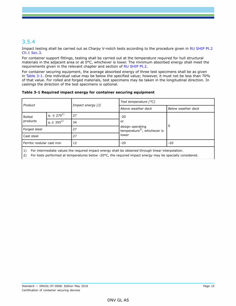
3.5.4 Impact testing shall be carried out as Charpy V-notch tests according to the procedure given in RU SHIP Pt.2Ch.1 Sec.3.For container support fittings, testing shall be carried out at the temperature required for hull structuralmaterials in the adjacent area or at 0°C, whichever is lower. The minimum absorbed energy shall meet therequirements given in the relevant chapter and section of RU SHIP Pt.2.For container securing equipment, the average absorbed energy of three test specimens shall be as givenin Table 3-1. One individual value may be below the specified value; however, it must not be less than 70%of that value. For rolled and forged materials, test specimens may be taken in the longitudinal direction. Incastings the direction of the test specimens is optional.
Table 3-1 Required impact energy for container securing equipment
Test temperature [°C]Product Impact energy [J]
Above weather deck Below weather deck
sf ≤ 2701) 27Rolledproducts sf ≥ 3551) 34
Forged steel 27
Cast steel 27
-20or
design operatingtemperature2), whichever islower
0
Ferritic nodular cast iron 12 -20 -20
1) For intermediate values the required impact energy shall be obtained through linear interpolation.2) For tests performed at temperatures below -20°C, the required impact energy may be specially considered.

Standard — DNVGL-ST-0068. Edition May 2016 Page 11Certification of container securing devices
DNV GL AS
SECTION 4 TYPE APPROVAL
4.1 GeneralType approval is based on plan approval and prototype testing, and will be issued in accordance with thegeneral requirements outlined in RU SHIP Pt.1 Ch.1 Sec.4 and class programme DNVGL CP 0338.Type approval certificates are issued to manufacturers of components. Such certificates are based on areview of the design, i.e. plan approval, and are issued for products that have been manufactured andprototype tested, and is only valid for the one manufacturing plant. Certificates are valid for 5 years and willbe listed on the internet site Approval Finder https://approvalfinder.dnvgl.com/.
4.2 Plan approval
4.2.1 For each equipment item, plans shall be submitted as required by Table 1-2 and, if relevant, Table 1-3.
4.2.2 Approval will be based on an evaluation of the strength of each securing device, as described in the followingsubsections. However, factors related to safe use will also be considered:
— Securing devices that function as mechanisms must have safe and reliable operation throughout theiroperational lifespan.
— The risk of incorrect application of securing devices should be minimised through design, marking orlabelling and user instructions.
— For devices that may have small margins against malfunction or failure, a more detailed analysis of safetywill be considered; such smaller margins may for instance be related to:
— wear or corrosion— small contact areas for load transfer— difficult or impossible verification that the device is properly attached and locked after application— enhanced need for maintenance.
For securing devices based on novel design solutions, or where the Society has special concern linked to theconditions described above, the design approval may be given for a limited time. The Society reserves theright to re-evaluate the design and, if necessary, withdraw type approvals. This will normally not have anyconsequences for devices that are already certified and delivered to the user. Product certificates will not bewithdrawn unless a securing device is shown not to be safe and reliable in use.
4.2.3 Securing devices may be subject to tension, compression or shear forces, or combinations thereof. The forcesmay be static or dynamic. However, during prototype testing the test specimens will normally be subject toone type of static force at a time.During operation, securing devices are normally subjected to cyclic loads. This shall be taken into account inthe design and choice of materials, so that the possibility of fatigue failure is minimised.For some devices subject to compression loads, e.g. tension/pressure elements and long bridge stackers,buckling strength may have to be considered.In general the SWL, in securing devices is not to exceed the safety factor S as given in [4.3.2].The SWL in container securing devices is typically 50% of the BL.

Standard — DNVGL-ST-0068. Edition May 2016 Page 12Certification of container securing devices
DNV GL AS
In Table 4-1, SWL are shown as typical values for selected types of the container securing devices. Forcontainer securing calculation purposes, SWL values as given in the product certificates of actual devicesshall be used as allowable limits.
Table 4-1 Typical SWL values and test loads for container securing devices
Item Type FigureSafe Working
Load(SWL) [kN]
Proof Load(PL) [kN]
Min. BreakingLoad (BL) [kN]
Lashings
1.1 Lashing rod 245 307 490
1.2 Lashing chain 80 100 200
1.3 Lashing steel wirerope
200 250 450
2 Turnbuckle
245 307 490
3 Penguin hook
245 307 490
4 D-Ring
245 307 490
5 Lashing plate
245 307 490

Standard — DNVGL-ST-0068. Edition May 2016 Page 13Certification of container securing devices
DNV GL AS
Item Type FigureSafe Working
Load(SWL) [kN]
Proof Load(PL) [kN]
Min. BreakingLoad (BL) [kN]
Twist locks and deck connections
210 263 420
6 Twist lock (single)
250 313 500
7 Flush ISO socket
250 313 500
250 313 500
8 Pedestal ISO socket
210 263 420
Tension 250 313 500
9 Dove tail socketwith twist lock
Shear 210 263 420
Standard — DNVGL-ST-0068. Edition May 2016 Page 14Certification of container securing devices
DNV GL AS
Item Type FigureSafe Working
Load(SWL) [kN]
Proof Load(PL) [kN]
Min. BreakingLoad (BL) [kN]
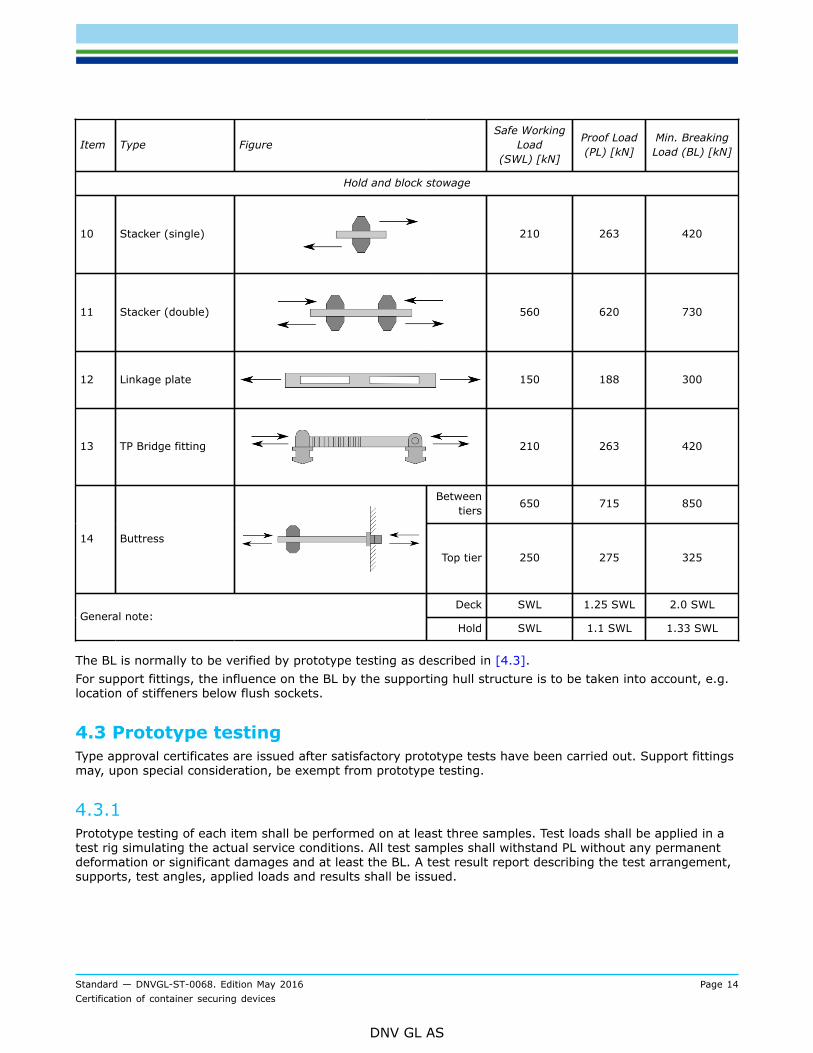
Hold and block stowage
10 Stacker (single)
210 263 420
11 Stacker (double)
560 620 730
12 Linkage plate
150 188 300
13 TP Bridge fitting
210 263 420
Betweentiers 650 715 850
14 Buttress
Top tier 250 275 325
Deck SWL 1.25 SWL 2.0 SWLGeneral note:
Hold SWL 1.1 SWL 1.33 SWL
The BL is normally to be verified by prototype testing as described in [4.3].For support fittings, the influence on the BL by the supporting hull structure is to be taken into account, e.g.location of stiffeners below flush sockets.
4.3 Prototype testingType approval certificates are issued after satisfactory prototype tests have been carried out. Support fittingsmay, upon special consideration, be exempt from prototype testing.
4.3.1 Prototype testing of each item shall be performed on at least three samples. Test loads shall be applied in atest rig simulating the actual service conditions. All test samples shall withstand PL without any permanentdeformation or significant damages and at least the BL. A test result report describing the test arrangement,supports, test angles, applied loads and results shall be issued.

Standard — DNVGL-ST-0068. Edition May 2016 Page 15Certification of container securing devices
DNV GL AS
4.3.2 Following safety factors SBL apply for securing devices and support fittings:
Safety factor in general: SBL = 2.0
For lashing ropes: SBL = 2.25
For lashing chains: SBL = 2.50
Typical values for SWL, PL and BL for most commonly used fittings as well as the test arrangement areshown in Table 4-1.
4.3.3 A prototype test may be required for an assembly consisting of several securing devices in order to verify thejoint performance of the assembly.
4.3.4 For fully automatic locks, an operational test is required as described in [4.4]. For novel designs of fullyautomatic locks, the operational test procedure will be evaluated by the Society on a case-by-case basis.
4.3.5 For support fittings which are to be welded into the hull structure, the test condition shall simulate thewelded, in-service condition. Furthermore the parts of support fitting which are directly integrated to the hullstructure shall have at least the same material grade and strength group of the hull structure where they arewelded into.
4.3.6 All welding-in pockets of support fittings shall be checked for tightness and delivered with proof issued by themanufacturer. The Society reserves the right to be present at tightness test.
4.3.7 Prototype tests shall be repeated latest after 5 years to renew the type approval certificate.
4.4 Operational testing of fully automatic locks
4.4.1 For fully automatic locks (FAL) operational testing shall be carried out in addition to prototype testing asgiven in [4.3]. Type approval certificate are issued after satisfactory prototype tests and operational testshave been carried out.
4.4.2 Operational test shall be performed on at least three test specimens. The test arrangement shall representrealistic stowage of ISO containers secured by FAL. The load scenario shall demonstrate that the FAL iscapable of withstanding transverse racking forces in combination with lifting forces in accordance withfollowing test arrangement and procedure. The test location and test jig shall be agreed by the Society.

Standard — DNVGL-ST-0068. Edition May 2016 Page 16Certification of container securing devices
DNV GL AS
Table 4-2 Test procedure for fully automatic locks
Type Test arrangement and loading scenarioTest Load
[kN]
Compressiveforce 1 96
Compressiveforce 2 35
Fullyautomaticlocks
Test setup:The distance between centre lines of the corner casting apertures on thetest jig shall be 4 mm less than distance between centre lines of the cornercasting apertures on the test platform.
Loading scenario:
First, the test jig shall be shifted in the direction of racking force as far aspossible within the clearance of the locks.
Subsequently, test forces shall be applied in the following sequence:
a) Compressive forces 1 and 2b) Racking force
Racking force 210

Standard — DNVGL-ST-0068. Edition May 2016 Page 17Certification of container securing devices
DNV GL AS
Type Test arrangement and loading scenarioTest Load
[kN]
Compressiveforce 350
Racking force 150
Fullyautomaticlocks
Test setup:The distance between center lines of the corner casting apertures on the testjig shall 5 mm less than distance between center lines of the corner castingapertures on the test platform.
Loading scenario:
First, the test jig shall be shifted in the direction of racking force as far aspossible within the clearance of the locks.
Subsequently, test forces shall be applied in the following sequence:
a) Compressive forceb) Racking forcec) Lifting force
Lifting force 275
Notes:
1) Two ISO top corner fittings in mint condition shall be fixed on the test platform.2) A stiff test jig, linking two ISO bottom corner fittings in mint condition, shall be used.3) The top and bottom apertures of all ISO corner fittings shall be exactly 65 mm wide.
4) The orientation of the racking force shall be always opposite to the nose of the fully automatic lock.5) During the sequential application of test forces, the previously applied forces shall be kept constant.6) Devices for application of test forces shall not laterally jam the test jig.7) Permanent deformations, incipient cracks, or failure of the lock as such will not be accepted.8) At least three randomly selected fully automatic locks shall be tested.

Standard — DNVGL-ST-0068. Edition May 2016 Page 18Certification of container securing devices
DNV GL AS
4.4.3 The operational test shall be witnessed by the Society. A test report shall be prepared and submitted by themanufacturer of the fully automatic lock.

Standard — DNVGL-ST-0068. Edition May 2016 Page 19Certification of container securing devices
DNV GL AS
SECTION 5 CASE-BY-CASE APPROVAL
5.1 As an alternative to type approval, the product certification may be based on case-by-case design approval inaccordance with approval principles described in Sec.4.

Standard — DNVGL-ST-0068. Edition May 2016 Page 20Certification of container securing devices
DNV GL AS
SECTION 6 PRODUCTION TESTING
6.1 General
6.1.1 Production testing shall be carried out as follows:At least 2% of all items shall be proof tested. For a delivery batch of less than 50 items at least one itemfrom each lot (including prototypes) shall be tested.The test load to be applied in proof tests is normally to be taken as 1.25 times the SWL for devices to beused on deck and 1.1 times SWL for devices intended for use in cargo holds. See Table 4-1. Upon completionof the proof test, each item shall be examined and confirmed to be free of permanent deformations andsignificant defects.
6.1.2 For support fittings which have to be welded-in for the purpose of testing, the scope of testing may bereduced to 0.5% of all items, provided that
— latest prototype test is not older than 12 months, and— a valid type approval certificate is available for these support fittings.
6.1.3 The certification may, as an alternative to the production testing described in [6.1.1], be based on a schemefor non-destructive examination, if agreed by the Society. The details of such a scheme shall be agreed in amanufacturing survey arrangement.
6.1.4 Non-standardised securing equipment, such as wires and chains, will be specially considered.
6.1.5 Where a lashing assembly consists of several devices (e.g. turnbuckles, twistlocks) supplied by differentmanufacturers, testing shall be carried out upon the assembly.
6.1.6 Where found necessary, the Society’s surveyor may request tests carried out beyond the prescribed scope,e.g. additional material testing.

Standard — DNVGL-ST-0068. Edition May 2016 Page 21Certification of container securing devices
DNV GL AS
SECTION 7 MARKING
7.1 Each item shall be marked with suitable identification marking to allow traceability to the product certificate.The marking shall include the manufacturer’s/supplier’s name or mark, type designation and, if relevant,charge or heat number.
Cha
nges
– h
isto
ric
Standard — DNVGL-ST-0068. Edition May 2016 Page 22Certification of container securing devices
DNV GL AS
CHANGES – HISTORICThere are currently no historical changes for this document.

DNV GLDriven by our purpose of safeguarding life, property and the environment, DNV GL enablesorganizations to advance the safety and sustainability of their business. We provide classification andtechnical assurance along with software and independent expert advisory services to the maritime,oil and gas, and energy industries. We also provide certification services to customers across a widerange of industries. Operating in more than 100 countries, our 16 000 professionals are dedicated tohelping our customers make the world safer, smarter and greener.
SAFER, SMARTER, GREENER