DNVGL-OS-C103: Structural design of column stabilised units - … · 2015-09-09 · Offshore...
42
OFFSHORE STANDARD DNV GL AS The electronic pdf version of this document found through http://www.dnvgl.com is the officially binding version. The documents are available free of charge in PDF format. DNVGL-OS-C103 Edition July 2015 Structural design of column stabilised units - LRFD method
Transcript of DNVGL-OS-C103: Structural design of column stabilised units - … · 2015-09-09 · Offshore...

OFFSHORE STANDARD
DNVGL-OS-C103 Edition July 2015
Structural design of column stabilised units - LRFD method
DNV GL AS
The electronic pdf version of this document found through http://www.dnvgl.com is the officially binding version. The documents are available free of charge in PDF format.

FOREWORD
DNV GL offshore standards contain technical requirements, principles and acceptance criteria related toclassification of offshore units.© DNV GL AS July 2015
Any comments may be sent by e-mail to [email protected]
This service document has been prepared based on available knowledge, technology and/or information at the time of issuance of this document. The use of thisdocument by others than DNV GL is at the user's sole risk. DNV GL does not accept any liability or responsibility for loss or damages resulting from any use ofthis document.

C
hang
es –
cur
rent
CHANGES – CURRENTGeneralThis document supersedes DNV-OS-C103, July 2014.
Text affected by the main changes in this edition is highlighted in red colour. However, if the changes
On 12 September 2013, DNV and GL merged to form DNV GL Group. On 25 November 2013 Det NorskeVeritas AS became the 100% shareholder of Germanischer Lloyd SE, the parent company of the GL Group,and on 27 November 2013 Det Norske Veritas AS, company registration number 945 748 931, changed itsname to DNV GL AS. For further information, see www.dnvgl.com. Any reference in this document to “DetNorske Veritas AS”, “Det Norske Veritas”, “DNV”, “GL”, “Germanischer Lloyd SE”, “GL Group” or any otherlegal entity name or trading name presently owned by the DNV GL Group shall therefore also be considereda reference to “DNV GL AS”.
involve a whole chapter, section or sub-section, normally only the title will be in red colour.
Main changes July 2015• GeneralThe revision of this document is part of the DNV GL merger, updating the previous DNV standard into a DNV GL format including updated nomenclature and document reference numbering, e.g.:
— Main class identification 1A1 becomes 1A.— DNV replaced by DNV GL.— DNV-RP-A201 to DNVGL-CG-0168. A complete listing with updated reference numbers can be found on
DNV GL's homepage on internet.
To complete your understanding, observe that the entire DNV GL update process will be implemented sequentially. Hence, for some of the references, still the legacy DNV documents apply and are explicitly indicated as such, e.g.: Rules for Ships has become DNV Rules for Ships.
In addition to the above stated main changes, editorial corrections may have been made.
Editorial corrections
Offshore standard, DNVGL-OS-C103 – Edition July 2015 Page 3Structural design of column stabilised units - LRFD method
DNV GL AS
C
onte
nts
CONTENTSCHANGES – CURRENT ................................................................................................. 3
CH. 1 INTRODUCTION ......................................................... 7Sec.1 Introduction.................................................................................................. 7
1 General .....................................................................................................71.1 General .............................................................................................71.2 Objectives .........................................................................................71.3 Assumptions and applications...............................................................7
2 References................................................................................................83 Definitions ................................................................................................8
3.1 Verbal forms ......................................................................................83.2 Terms ...............................................................................................8
4 Symbols....................................................................................................94.1 Latin characters..................................................................................94.2 Greek characters ................................................................................94.3 Abbreviations.....................................................................................9
CH. 2 TECHNICAL CONTENT .............................................. 10Sec.1 Structural categorisation,
material selection and inspection principles................................................ 101 General ...................................................................................................10
1.1 Scope .............................................................................................10
2 Structural categorisation ........................................................................103 Material selection ...................................................................................11
3.1 General ...........................................................................................113.2 Design and service temperatures ........................................................11
4 Inspection categories .............................................................................114.1 General ...........................................................................................11
5 Categorisation and inspection level for typical column-stabilised unit details.....................................................................................................125.1 General ...........................................................................................12
Sec.2 Design loads................................................................................................ 151 Introduction ...........................................................................................15
1.1 General ...........................................................................................15
2 Definition................................................................................................152.1 Load point .......................................................................................15
3 Permanent loads (G) ..............................................................................154 Variable functional loads (Q) ..................................................................15
4.1 General ...........................................................................................154.2 Tank loads.......................................................................................16
5 Environmental loads (E) .........................................................................175.1 General ...........................................................................................175.2 Sea pressures ..................................................................................175.3 Wind loads.......................................................................................185.4 Heavy components ...........................................................................18
Offshore standard, DNVGL-OS-C103 – Edition July 2015 Page 4Structural design of column stabilised units - LRFD method
DNV GL AS

C
onte
nts
6 Deformation loads (D) ............................................................................197 Accidental loads (A) ...............................................................................198 Fatigue loads ..........................................................................................19
8.1 General ...........................................................................................19
9 Combination of loads ..............................................................................199.1 General ...........................................................................................19
Sec.3 Ultimate limit states (ULS).......................................................................... 201 General ...................................................................................................20
1.1 General ...........................................................................................201.2 Global capacity.................................................................................201.3 Transit condition...............................................................................21
2 Method of analysis..................................................................................212.1 General ...........................................................................................21
3 Scantlings and weld connections ............................................................224 Air gap....................................................................................................22
4.1 General ...........................................................................................22
Sec.4 Fatigue limit states (FLS) ............................................................................ 231 General ...................................................................................................23
1.1 General ...........................................................................................23
2 Fatigue Analysis .....................................................................................242.1 General ...........................................................................................242.2 World-wide operation ........................................................................242.3 Restricted operation .........................................................................242.4 Simplified fatigue analysis..................................................................242.5 Stochastic fatigue analysis .................................................................25
Sec.5 Accidental limit states (ALS) ....................................................................... 261 General ...................................................................................................26
1.1 General ...........................................................................................26
2 Collision..................................................................................................262.1 General ...........................................................................................26
3 Dropped object .......................................................................................273.1 General ...........................................................................................27
4 Fire .........................................................................................................274.1 General ...........................................................................................27
5 Explosion ................................................................................................275.1 General ...........................................................................................27
6 Heeled condition.....................................................................................286.1 General ...........................................................................................28
Sec.6 Special considerations................................................................................. 291 Redundancy............................................................................................29
1.1 General ...........................................................................................291.2 Brace arrangements..........................................................................29
2 Support of mooring equipment, towing brackets etc. .............................293 Structural details ....................................................................................29
3.1 General ...........................................................................................29
Offshore standard, DNVGL-OS-C103 – Edition July 2015 Page 5Structural design of column stabilised units - LRFD method
DNV GL AS
C
onte
nts
CH. 3 CLASSIFICATION AND CERTIFICATION.................... 30Sec.1 Classification............................................................................................... 301 General ...................................................................................................30
1.1 Introduction.....................................................................................301.2 Application.......................................................................................301.3 Documentation.................................................................................30
APP. A PERMANENTLY INSTALLED UNITS.......................... 311 Introduction ...........................................................................................31
1.1 Application.......................................................................................311.2 Facilities for inspection on location ......................................................31
2 Fatigue ...................................................................................................312.1 Design fatigue factors .......................................................................312.2 Splash zone .....................................................................................32
APP. B METHODS AND MODELS FOR DESIGN OF COLUMN-STABILISED UNITS.................................. 33
1 Methods and models ...............................................................................331.1 General ...........................................................................................331.2 World wide operation ........................................................................331.3 Benign waters or restricted areas........................................................33
APP. C COLUMN-STABILIZED UNITS STRENGTH REQUIREMENTS FOR TRANSIT IN ICE ................... 35
1 General ...................................................................................................351.1 Introduction ....................................................................................351.2 Scope .............................................................................................351.3 Application.......................................................................................351.4 Definitions .......................................................................................36
2 Ice design loads.....................................................................................382.1 Height of the ice load area .................................................................382.2 Ice pressure ....................................................................................38
3 Shell plating ...........................................................................................393.1 Vertical extension of ice strengthening for plating .................................393.2 Plate thickness in the ice belt .............................................................39
4 Frames ...................................................................................................404.1 Vertical extension of ice framing .........................................................404.2 Transverse and longitudinal frames.....................................................404.3 Structural details ..............................................................................404.4 Ice stringers and web frames .............................................................40
5 Special arrangement ..............................................................................405.1 Bracings air clearance .......................................................................405.2 Towing arrangement .........................................................................405.3 Equipment and structures mounted in ice-belt region ............................41
Offshore standard, DNVGL-OS-C103 – Edition July 2015 Page 6Structural design of column stabilised units - LRFD method
DNV GL AS

Cha
pter
1
Sec
tion
1
CHAPTER 1 INTRODUCTIONSECTION 1 INTRODUCTION
1 General
1.1 GeneralThis offshore standard provides requirements and guidance for the structural design of column-stabilised units, constructed in steel.
1.2 ObjectivesThe objectives of this standard are to:
— provide an internationally acceptable standard of safety by defining minimum requirements for design of column-stabilised units
— serve as a contractual reference document between suppliers and purchasers
— serve as a guideline for designers, suppliers, purchasers and regulators
— specify procedures and requirements for column-stabilised units subject to DNV GL verification.
1.3 Assumptions and applications1.3.1 The requirements and guidance documented in this standard are generally applicable to all configurations of column-stabilised units, including those with:
— ring pontoons
— twin pontoons.
1.3.2 A column-stabilised unit is a floating structure that can be relocated. A column-stabilised unit normally consists of a deck box with a number of widely spaced, large diameter, supporting columns that are attached to submerged pontoons.
1.3.3 Column-stabilised unit may be kept on station by either a passive mooring system, e.g. anchor lines, or an active mooring system, e.g. thrusters, or a combination of these methods.
1.3.4 Requirements concerning mooring and riser systems are not considered in this standard.
1.3.5 A column-stabilised unit may be designed to function in a number of modes, e.g. transit, operational and survival. Limiting design criteria modes of operation shall be clearly established and documented. Such limiting design criteria shall include relevant consideration of the following items:
— intact condition, structural strength
— damaged condition, structural strength
— air gap
— watertight integrity and hydrostatic stability.
1.3.6 For novel designs, or unproved applications of designs where limited or no direct experience exists, relevant analyses and model testing, shall be performed to clearly demonstrate that an acceptable level of safety is obtained.
1.3.7 The standard has been written for general world-wide application. Governmental regulations may include requirements in excess of the provisions given by this standard depending on the size, type, location and intended service of an offshore unit or installation.
Offshore standard, DNVGL-OS-C103 – Edition July 2015 Page 7Structural design of column stabilised units - LRFD method
DNV GL AS

Cha
pter
1
Sec
tion
1
2 ReferencesThe Offshore Standards, Recommended Practices and Classification Notes given in Table 1 are referred to in this standard.3 Definitions
3.1 Verbal forms
3.2 Terms3.2.1 Transit conditions: All unit movements from one geographical location to another.
3.2.2 Standard terms are given in DNVGL-OS-C101.
Table 1 DNVGL and DNV reference documents
Reference Title
DNVGL-OS-A101 Safety principles and arrangement
DNVGL-OS-B101 Metallic materials
DNVGL-OS-C101 Design of offshore steel structures, general - LRFD method
DNVGL-OS-C301 Stability and watertight integrity
DNVGL-OS-C401 Fabrication and testing of offshore structures
DNVGL-OS-D101 Marine and machinery systems and equipment
DNVGL-OS-D301 Fire protection
DNVGL-OS-E301 Position mooring
DNVGL-RP-C103 Column-stabilised units
DNVGL-RP-C201 Buckling of plated structures
DNV-RP-C202 Buckling Strength of Shells
DNVGL-RP-C203 Fatigue strength analysis
DNV-RP-C205 Environmental Conditions and Environmental Loads
DNV Classification Notes 30.1 Buckling Strength Analysis (Bars and Frames)
DNV Classification Notes 30.6 Structural Reliability Analysis of Marine Structures
DNV-OS-H101 to H206 DNV Marine Operation (VMO) standards
Table 2 Verbal forms
Term Definitionshall verbal form used to indicate requirements strictly to be followed in order to conform to the documentshould verbal form used to indicate that among several possibilities one is recommended as particularly suitable,
without mentioning or excluding others, or that a certain course of action is preferred but not necessarily required
may verbal form used to indicate a course of action permissible within the limits of the document
Offshore standard, DNVGL-OS-C103 – Edition July 2015 Page 8Structural design of column stabilised units - LRFD method
DNV GL AS
Cha
pter
1
Sec
tion
1
4 Symbols4.1 Latin characters
4.2 Greek characters
4.3 AbbreviationsAbbreviations used in this standard are given in DNVGL-OS-C101.
= the intercept of the design S-N curve with the log N axisah = horizontal acceleration av = vertical acceleration g0 = 9.81 m/s2 acceleration due to gravityh = Weibull shape parameterhop = vertical distance from the load point to the position of maximum filling heightM = mass of cargo, equipment or other componentsm = the inverse slope of the S-N curven0 = total number of stress fluctuations during the lifetime of the structureni = number of stress fluctuations in i yearspd = design pressure pdyn = pressure head due to flow through pipeszb = vertical distance in m from the moulded baseline to the load pointCw = reduction factor due to wave particle motion (Smith effect) DD = vertical distance from the moulded baseline to the underside of the deck structureDFF = Design Fatigue FactorPHd = horizontal design forcePVd = vertical design forceTE = extreme operational draught measured vertically from the moulded baseline to the assigned load
waterline.
Γ = gamma function α = angleρ = densityγc = contingency factorτd = nominal design shear stress in the girder adjusted for cut-outs γf = partial load factor γf,E = partial load factor for environmental loadsγf,G,Q = partial load factor for functional and variable loads.
a
Offshore standard, DNVGL-OS-C103 – Edition July 2015 Page 9Structural design of column stabilised units - LRFD method
DNV GL AS

Cha
pter
2
Sec
tion
1
CHAPTER 2 TECHNICAL CONTENTSECTION 1 STRUCTURAL CATEGORISATION, MATERIAL SELECTION AND INSPECTION PRINCIPLES
1 General
1.1 Scope1.1.1 This section describes the structural categorisation, selection of steel materials and inspection principles to be applied in design and construction of column-stabilised units.
1.1.2 The structural application categories are determined based on the structural significance, consequences of failure and the complexity of the joints. The structural application category set the selection of steel quality and the inspection extent of the welds.
1.1.3 The steel grades selected for structural components shall be related to weldability and requirements for toughness properties and shall be in compliance with the requirements given in the DNVGL-OS-B101.
2 Structural categorisationApplication categories for structural components are defined in DNVGL-OS-C101 Ch.2 Sec.3. Structural members of column-stabilised units are grouped as follows:
Special category
a) Portions of deck plating, heavy flanges, and bulkheads within the upper hull or platform which form “box” or “I” type supporting structure which receive major concentrated loads.
b) External shell structure in way of intersections of vertical columns, decks and lower hulls.c) Major intersections of bracing members.d) “Through” material used at connections of vertical columns, upper platform decks and upper or lower
hulls which are designed to provide proper alignment and adequate load transfer.e) External brackets, portions of bulkheads, and frames which are designed to receive concentrated loads
at intersections of major structural members.f) Areas of concentrated loads in elements of supporting structure of anchor line fairleads and winches,
crane pedestals, flare etc.
Figure 1 to Figure 4 show typical examples of special structures.
Primary category
a) Deck plating, heavy flanges, and bulkheads within the upper hull or platform which form “box” or “I” type supporting structure which do not receive major concentrated loads.
b) External shell structure of vertical columns, lower and upper hulls, and diagonal and horizontal braces.c) Bulkheads, decks, stiffeners and girders which provide local reinforcement or continuity of structure in
way of intersections, except areas where the structure is considered for special application.d) Main support structure of heavy substructures and equipment, e.g. anchor line fairleads, cranes,
drillfloor substructure, life boat platform, thruster foundation and helicopter deck.
Secondary category
a) Upper platform decks, or decks of upper hulls except areas where the structure is considered primary or special application.
b) Bulkheads, stiffeners, flats or decks and girders in vertical columns, decks, lower hulls, diagonal and horizontal bracing, which are not considered as primary or special application.
c) Deckhouses.d) Other structures not categorised as special or primary.
Offshore standard, DNVGL-OS-C103 – Edition July 2015 Page 10Structural design of column stabilised units - LRFD method
DNV GL AS

Cha
pter
2
Sec
tion
1
3 Material selection3.1 General3.1.1 Material specifications shall be established for all structural materials. Such materials shall be suitable for their intended purpose and have adequate properties in all relevant design conditions. Material selection shall be undertaken in accordance with the principles given in DNVGL-OS-C101.
3.1.2 When considering criteria appropriate to material grade selection, adequate consideration shall be given to all relevant phases in the life cycle of the unit. In this connection there may be conditions and criteria, other than those from the in-service operational phase that provide the design requirements in respect to the selection of material. (Such criteria may, for example, be design temperature and/or stress levels during marine operations.)
3.1.3 In structural cross-joints essential for the overall structural integrity where high tensile stresses are acting normal to the plane of the plate, the plate material shall be tested to prove the ability to resist lamellar tearing (Z-quality).
3.1.4 Material designations are defined in DNVGL-OS-C101.
3.2 Design and service temperatures3.2.1 The design temperature for a unit is the reference temperature for assessing areas where the unit can be transported, installed and operated. The design temperature shall be lower or equal to the lowest mean daily temperature in air for the relevant areas. For seasonal restricted operations the lowest mean daily temperature in air for the season may be applied.
3.2.2 The service temperatures for different parts of a unit apply for selection of structural steel. The service temperatures are defined as presented in [3.2.3] to [3.2.6]. In case different service temperatures are defined in [3.2.3] to [3.2.6] for a structural part the lower specified value shall be applied.
3.2.3 External structures above the light transit waterline shall not be designed for a service temperature higher than the design temperature for the unit.
However, for column-stabilised units of conventional type, the pontoon deck need not be designed for service temperatures lower than 0ºC.
3.2.4 External structures below the light transit waterline need not be designed for service temperatures lower than 0ºC.
3.2.5 Internal structures of columns, pontoons and decks shall have the same service temperature as the adjacent external structure, if not otherwise documented.
3.2.6 Internal structures in way of permanently heated rooms need not to be designed for service temperatures lower than 0ºC.
4 Inspection categories
4.1 General4.1.1 Welding and the extent of non-destructive testing during fabrication, shall be in accordance with the requirements stipulated for the appropriate inspection category as defined in DNVGL-OS-C101 Ch.2 Sec.3.
4.1.2 Inspection categories determined in accordance with DNVGL-OS-C101 Ch.2 Sec.3 provide requirements for the minimum extent of required inspection. When considering the economic consequence that repair during in-service operation may entail, for example, in way of complex connections with limited or difficult access, it may be considered prudent engineering practice to require more demanding requirements for inspection than the required minimum.
Offshore standard, DNVGL-OS-C103 – Edition July 2015 Page 11Structural design of column stabilised units - LRFD method
DNV GL AS

Cha
pter
2
Sec
tion
1
4.1.3 When determining the extent of inspection and the locations of required NDT, in additional to evaluating design parameters (for example fatigue utilisation), consideration should be given to relevant fabrication parameters including:— location of block (section) joints— manual versus automatic welding— start and stop of weld, etc.
5 Categorisation and inspection level for typical column-stabilised unit details
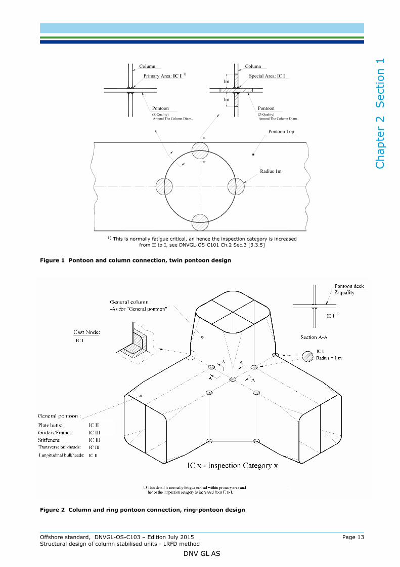
5.1 General5.1.1 Figure 1 to Figure 4 illustrate minimum requirements for structural categorisation and extent of inspection for typical column-stabilised unit configurations.
5.1.2 In way of the pontoon and column connection as indicated in Figure 1 and Figure 2, the pontoon deckplate should be the continuous material. These plate fields should be of material with through-thickness properties (Z-quality material).
5.1.3 Shaded areas indicated in the figures are intended to be three-dimensional in extent. This implies that, in way of these locations, the shaded area is not only to apply to the outer surface of the connection, but is also to extend into the structure. However, stiffeners and stiffener brackets within this area should be of primary category and the bracket toe locations on the stiffeners should be designated with mandatory MPI.
5.1.4 Stiffeners welded to a plate categorised as special area should be welded with full penetration welds and no notches should be used.
5.1.5 The inspection categories for general pontoon, plate butt welds and girder welds to the pontoon shell are determined based upon, amongst others, accessibility and fatigue utilisation.
5.1.6 Major bracket toes should be designated as locations with a mandatory requirement for MPI. In way of the brace connections as indicated Figure 3, the brace and brace bracket plate fields should be the continuous material. These plate fields should be material with through-thickness properties (Z-quality material).
5.1.7 In way of the column and upper hull connection as indicated in Figure 4 the upper hull deckplate should be the continuous material. These plate fields should be material with through-thickness properties (Z-quality material).
Offshore standard, DNVGL-OS-C103 – Edition July 2015 Page 12Structural design of column stabilised units - LRFD method
DNV GL AS
Cha
pter
2
Sec
tion
1
1) This is normally fatigue critical, an hence the inspection category is increasedfrom II to I, see DNVGL-OS-C101 Ch.2 Sec.3 [3.3.5]
Figure 1 Pontoon and column connection, twin pontoon design
Figure 2 Column and ring pontoon connection, ring-pontoon design
Pontoon(Z-Quality)
Column
Around The Column Diam..
Radius 1m
Pontoon Top
Primary Area: IC I
1m
Around The Column Diam..(Z-Quality)
Pontoon
Special Area: IC I
Column
1m
1)
IC II
IC III
Offshore standard, DNVGL-OS-C103 – Edition July 2015 Page 13Structural design of column stabilised units - LRFD method
DNV GL AS

Cha
pter
2
Sec
tion
1
Figure 3 Brace connection
Figure 4 Connection column and upper hull
Offshore standard, DNVGL-OS-C103 – Edition July 2015 Page 14Structural design of column stabilised units - LRFD method
DNV GL AS
Cha
pter
2
Sec
tion
2
SECTION 2 DESIGN LOADS1 Introduction
1.1 General1.1.1 The requirements in this section define and specify load components and load combinations to be considered in the overall strength analysis as well as design pressures applicable for local design.
1.1.2 Characteristic loads shall be used as reference loads. Design loads are, in general, defined in DNVGL-OS-C101 and described in DNVGL-RP-C103 and DNV-RP-C205. Guidance concerning load categories relevant for column-stabilised unit designs are given in this section.
2 Definition
2.1 Load point2.1.1 The load point for which the design pressure for a plate field shall be calculated, is defined as midpoint of a horizontally stiffened plate field, and half of the stiffener spacing above the lower support of vertically stiffened plate field, or at lower edge of plate when the thickness is changed within the plate field.
2.1.2 The load point for which the design pressure for a stiffener shall be calculated, is defined as midpoint of the span. When the pressure is not varied linearly over the span, the design pressure shall be taken as the greater of the pressure at the midpoint, and the average of the pressures calculated at each end of the stiffener.
2.1.3 The load point for which the design pressure for a girder shall be calculated, is defined as midpoint of the load area.
3 Permanent loads (G)Permanent loads are loads that will not vary in magnitude, position, or direction during the period considered, and include:
— lightweight of the unit, including mass of permanently installed modules and equipment, such as accommodation, helideck, drilling and production equipment
— hydrostatic pressures resulting from buoyancy— pretension in respect to mooring, drilling and production systems, e.g. mooring lines, risers etc. See
DNVGL-OS-E301.
4 Variable functional loads (Q)
4.1 General4.1.1 Variable functional loads are loads that may vary in magnitude, position and direction during the period under consideration.
4.1.2 Except where analytical procedures or design specifications otherwise require, the value of the variable loads utilised in structural design shall be taken as either the lower or upper design value, whichever gives the more unfavourable effect. Variable loads on deck areas for local design are given in DNVGL-OS-C101 Ch.2 Sec.2 [4.2].
4.1.3 Variations in operational mass distributions, including variations in tank load conditions in pontoons, shall be adequately accounted for in the structural design.
4.1.4 Design criteria resulting from operational requirements shall be fully considered. Examples of such operations may be:
— drilling, production, workover, and combinations thereof
Offshore standard, DNVGL-OS-C103 – Edition July 2015 Page 15Structural design of column stabilised units - LRFD method
DNV GL AS

Cha
pter
2
Sec
tion
2
— consumable re-supply procedures— maintenance procedures
— possible mass re-distributions in extreme conditions.
4.1.5 Dynamic loads resulting from flow through air pipes during filling operations shall be adequately considered in the design of tank structures.
4.2 Tank loads4.2.1 A minimum design density (ρ) of 1.025 t/m3 should be considered in the determination of the required scantlings of tank structures.
4.2.2 The extent to which it is possible to fill sounding, venting or loading pipe arrangements shall be fully accounted for in determination of the maximum design pressure to which a tank may be subjected to.
4.2.3 Dynamic pressure heads resulting from filling of such pipes shall be included in the design pressure head where such load components are applicable.
4.2.4 All tanks shall be designed for the following internal design pressure:
4.2.5 For tanks where the air pipe may be filled during filling operations, the following additional internal design pressure conditions shall be considered:
pd = (ρ g0 hop + pdyn) γf,G,Q (kN/m2)
pdyn = Pressure (kN/m2) due to flow through pipes, minimum 25 kN/m2.
Guidance note:This internal pressure need not to be combined with extreme environmental loads. Normally only static global response need to be considered.
---e-n-d---of---g-u-i-d-a-n-c-e---n-o-t-e---
4.2.6 For external plate field boundaries, it is allowed to consider the external pressure up to the lowest waterline occurring in the environmental extreme condition, including relative motion of the unit.
Guidance note:For preliminary design calculations, av may be taken as 0.3 g0 and external pressure for external plate field boundaries may be taken up to half the pontoon height.
---e-n-d---of---g-u-i-d-a-n-c-e---n-o-t-e---
4.2.7 In cases where the maximum filling height is less than the height to the top of the air pipe, it shall be ensured that the tank will not be over-pressured during operation and tank testing conditions.
4.2.8 Requirements for testing of tank tightness and structural strength are given in DNVGL-OS-C401 Ch.2 Sec.4.
av = maximum vertical acceleration, (m/s2), being the coupled motion response applicable to the tank in question
hop = vertical distance (m) from the load point to the position of maximum filling height. For tanks adjacent to the sea that are situated below the extreme operational draught (TE), hop should not be taken less than from the load point to the static sea level.Descriptions and requirements related to different tank arrangements are given in DNVGL-OS-D101 Ch.2 Sec.3 [3.3].
γf,G,Q = partial load factor, for permanent and functional loads see Sec.3 Table 1γf,E = partial load factor for environmental loads, see Sec.3 Table 1.
pd ρ g0hop γf G Q, ,avg0-------γ f E,+
kN m2⁄( )=
Offshore standard, DNVGL-OS-C103 – Edition July 2015 Page 16Structural design of column stabilised units - LRFD method
DNV GL AS

Cha
pter
2
Sec
tion
2
5 Environmental loads (E)5.1 General5.1.1 General considerations for environmental loads are given in DNVGL-OS-C101 Ch.2 Sec.1 [5] and Sec.2 [6], and DNV-RP-C205.
5.1.2 Combinations of environmental loads are stated in DNVGL-OS-C101 Ch.2 Sec.2 Table 2-4.
5.1.3 Typical environmental loads to be considered in the structural design of a column-stabilised unit are:
— wave loads, including variable pressure, inertia, wave 'run-up', and slamming loads— wind loads— current loads— snow and ice loads.
5.1.4 The following responses due to environmental loads shall be considered in the structural design of a column-stabilised unit:
— dynamic stresses for all limit states— rigid body motion, e.g. in respect to air gap and maximum angles of inclination— sloshing— slamming induced vibrations— vortex induced vibrations,e.g. resulting from wind loads on structural elements in a flare tower— environmental loads from mooring and riser system.
5.1.5 For column-stabilised units with traditional catenary mooring systems, earthquake loads may normally be ignored.
5.2 Sea pressures5.2.1 For load conditions where environmental load effects shall be considered the pressures resulting from sea loading are to include consideration of the relative motion of the unit.
5.2.2 The design sea pressure acting on pontoons and columns of column-stabilised platforms in operating conditions shall be taken as:
where
and
TE = operational draught (m) measured vertically from the moulded baseline to the assigned load waterline. If the unit has more than one operational draught, the draught providing the highest pressure is to be used.
Cw = reduction factor due to wave particle motion (Smith effect) Cw = 0.9 unless otherwise documented DD = vertical distance in m from the moulded baseline to the underside of the deck structure
(the largest relative distance from moulded baseline to the wave crest may replace DD if this is proved smaller)
zb = vertical distance in m from the moulded baseline to the load pointps = permanent sea pressurepe = environmental sea pressure.
pd ps γf G Q , , pe γf E,⋅ +⋅=
ps ρ g0Cw TE zb–( ) kN m2⁄( ) 0 ≥=
pe ρg0 Cw DD zb–( ) kN m2⁄( ) for zb TE≥=
pe ρg0 Cw DD TE–( ) kN m2⁄( ) for zb T< E=
Offshore standard, DNVGL-OS-C103 – Edition July 2015 Page 17Structural design of column stabilised units - LRFD method
DNV GL AS
Cha
pter
2
Sec
tion
2
5.2.3 When pressures are acting on both sides of bulkheads, the load factor shall be applied to the net pressure.5.2.4 The Smith effect (Cw = 0.9) shall only be applied for loading conditions including extreme wave conditions.
5.3 Wind loads5.3.1 Wind loads shall be accounted for in the design of topside structures subject to significant wind exposure, e.g. modules, equipment, exposed structures on deck etc. The mean wind speed over 1 minute period at actual position above the sea level shall be used, when the wind loads are combined with accelerations loads from waves.
5.3.2 For structures where wind loads are governing, the mean wind speed period is to be reduced.
Guidance note:For structures not being sensitive to wind gusts a mean wind speed of 3 s may be used for structures with maximum dimension of 50 m and 15 s for larger structures.
---e-n-d---of---g-u-i-d-a-n-c-e---n-o-t-e---
5.3.3 For structures where Vortex-Shedding may occur, additional assessments of the structure are to be carried out.
Guidance note:It is recommended to design the structure so that the structure is not prone to Vortex -Shedding. See DNV-RP-C205 for further information.
---e-n-d---of---g-u-i-d-a-n-c-e---n-o-t-e---
5.3.4 The pressure acting on vertical external bulkheads exposed to wind shall not be less than 2.5 kN/m2, unless otherwise documented.
5.3.5 For units intended for unrestricted service (worldwide operation) a wind speed of v1min10m=51.5 m/s for 100year return period will cover most locations. For units intended for long term service at one offshore location relevant site specific values are to be used. Wind speed values for some locations might be found in DNVGL-OS-E301 Ch.2 Sec.1 [2.3.4].
5.3.6 Further details regarding wind design loads are given in DNV-RP-C205.
Guidance note:For units intended for World Wide Operation the wind profile as given in DNV-RP-C205 sec.2.3.2.11 may be used. For units intended for long term service at one offshore location appropriate wind profile is to be used.
---e-n-d---of---g-u-i-d-a-n-c-e---n-o-t-e---
5.4 Heavy componentsThe forces acting on supporting structures and lashing systems for rigid units of cargo, equipment or other structural components should be taken as:
For components exposed to wind, a horizontal force due to the design gust wind shall be added to PHd.
Further considerations with respect to environmental loads are given in DNV-RP-C205.
av = vertical acceleration (m/s2)ah = horizontal acceleration (m/s2)M = mass of cargo, equipment or other
components (t) PVd = vertical design forcePHd = horizontal design force.
PVd g0γf G Q , , avγf E,+( ) M (kN) =
PHd ahγf E, M (kN)=
Offshore standard, DNVGL-OS-C103 – Edition July 2015 Page 18Structural design of column stabilised units - LRFD method
DNV GL AS

Cha
pter
2
Sec
tion
2
6 Deformation loads (D)Deformation loads are loads caused by inflicted deformations, such as:— temperature loads
— built-in deformations.
Further details and description of deformation loads are given in DNVGL-OS-C101 Ch.2 Sec.2 [8].
7 Accidental loads (A)The following ALS events shall be considered in respect to the structural design of a column-stabilised unit:
— collision
— dropped objects, e.g. from crane handling
— fire
— explosion
— unintended flooding
— abnormal wave events.
Requirements and guidance on accidental loads are given in DNVGL-OS-C101 and generic loads are given in DNVGL-OS-A101.
8 Fatigue loads
8.1 General8.1.1 Repetitive loads, which may lead to significant fatigue damage, shall be evaluated. The following listed sources of fatigue loads shall, where relevant, be considered:
— waves (including those loads caused by slamming and variable (dynamic) pressures).
— wind (especially when vortex induced vibrations may occur)
— currents (especially when vortex induced vibrations may occur)
— mechanical loading and unloading, e.g. crane loads.
The effects of both local and global dynamic response shall be properly accounted for when determining response distributions related to fatigue loads.
8.1.2 Further considerations in respect to fatigue loads are given in DNVGL-RP-C203 and DNV-RP-C205.
9 Combination of loads
9.1 General9.1.1 Load factors and load combinations for the design limit states are in general, given in DNVGL-OS-C101.
9.1.2 Structural strength shall be evaluated considering all relevant, realistic load conditions and combinations. Scantlings shall be determined on the basis of criteria that combine, in a rational manner, the effects of relevant global and local responses for each individual structural element.
Further guidance on relevant load combinations is given in DNVGL-RP-C103.
9.1.3 A sufficient number of load conditions shall be evaluated to ensure that the characteristic largest (or smallest) response, for the appropriate return period, has been established.
Offshore standard, DNVGL-OS-C103 – Edition July 2015 Page 19Structural design of column stabilised units - LRFD method
DNV GL AS
Cha
pter
2
Sec
tion
3
SECTION 3 ULTIMATE LIMIT STATES (ULS)1 General
1.1 General1.1.1 General requirements in respect to methods of analysis and capacity checks are given in DNVGL-OS-C101.
Detailed considerations with respect to analysis methods and models are given in DNVGL-RP-C103.
1.1.2 Both global and local capacity shall be checked with respect to ULS. The global and local stresses shall be combined in an appropriate manner.
1.1.3 Analytical models shall adequately describe the relevant properties of loads, stiffness, displacement, response, and satisfactorily account for the local system, effects of time dependency, damping and inertia.
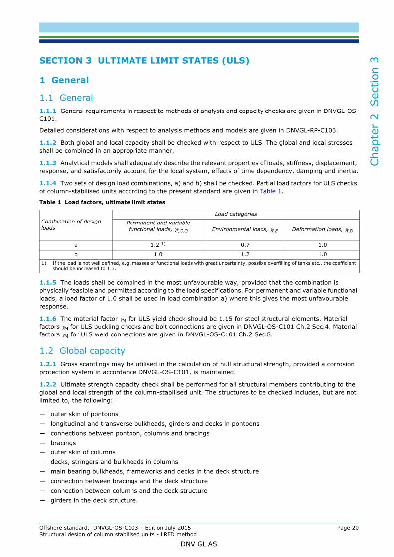
1.1.4 Two sets of design load combinations, a) and b) shall be checked. Partial load factors for ULS checks of column-stabilised units according to the present standard are given in Table 1.
1.1.5 The loads shall be combined in the most unfavourable way, provided that the combination is physically feasible and permitted according to the load specifications. For permanent and variable functional loads, a load factor of 1.0 shall be used in load combination a) where this gives the most unfavourable response.
1.1.6 The material factor γM for ULS yield check should be 1.15 for steel structural elements. Material factors γM for ULS buckling checks and bolt connections are given in DNVGL-OS-C101 Ch.2 Sec.4. Material factors γM for ULS weld connections are given in DNVGL-OS-C101 Ch.2 Sec.8.
1.2 Global capacity1.2.1 Gross scantlings may be utilised in the calculation of hull structural strength, provided a corrosion protection system in accordance DNVGL-OS-C101, is maintained.
1.2.2 Ultimate strength capacity check shall be performed for all structural members contributing to the global and local strength of the column-stabilised unit. The structures to be checked includes, but are not limited to, the following:
— outer skin of pontoons— longitudinal and transverse bulkheads, girders and decks in pontoons— connections between pontoon, columns and bracings— bracings— outer skin of columns— decks, stringers and bulkheads in columns— main bearing bulkheads, frameworks and decks in the deck structure— connection between bracings and the deck structure — connection between columns and the deck structure— girders in the deck structure.
Table 1 Load factors, ultimate limit states
Combination of design loads
Load categories
Permanent and variable functional loads, γf,G,Q Environmental loads, γf,E Deformation loads, γf,D
a 1.2 1) 0.7 1.0
b 1.0 1.2 1.01) If the load is not well defined, e.g. masses or functional loads with great uncertainty, possible overfilling of tanks etc., the coefficient
should be increased to 1.3.
Offshore standard, DNVGL-OS-C103 – Edition July 2015 Page 20Structural design of column stabilised units - LRFD method
DNV GL AS

Cha
pter
2
Sec
tion
3
1.3 Transit condition1.3.1 The structure shall be analysed for zero forward speed. For units in transit with high speed, also maximum speed shall be considered in the load and strength calculations.Guidance note:Roll and pitch motion at resonance should be somewhat smaller than calculated by a linear wave theory due to flow of water on top of the pontoons. This effect may be accounted for provided rational analysis or tests prove its magnitude.
---e-n-d---of---g-u-i-d-a-n-c-e---n-o-t-e---
1.3.2 Slamming on bracings shall be considered as a possible limiting criterion for operation in transit. The effect of forward speed shall be accounted for in the slamming calculations.
2 Method of analysis
2.1 General2.1.1 The analysis shall be performed to evaluate the structural capacity due to global and local effects. Consideration of relevant analysis methods and procedures are given in DNVGL-RP-C103, and in App.B.
2.1.2 Model testing shall be performed when significant non-linear effects cannot be adequately determined by direct calculations. In such cases, time domain analysis may also be considered as being necessary. Model tests shall also be performed for new types of column-stabilised units.
2.1.3 Where non-linear effects may be considered insignificant, or where such loads may be satisfactorily accounted for in a linear analysis, a frequency domain analysis may be adequately and satisfactorily undertaken. Transfer functions for structural response shall be established by analysis of an adequate number of wave directions, with an appropriate radial spacing. A sufficient number of periods shall be analysed to:
— adequately cover the site specific wave conditions— satisfactorily describe transfer functions at, and around, the wave “cancellation” and “amplifying”
periods — satisfactorily describe transfer functions at, and around, the heave resonance period of the unit.
2.1.4 Global, wave-frequency, structural responses shall be established by an appropriate methodology, e.g.:
— a regular wave analysis— a “design wave” analysis— a stochastic analysis.
2.1.5 Design waves established based on the “design wave” method, see DNVGL-RP-C103, shall be based on the 90% fractile value of the extreme response distribution (100 years return period) developed from contour lines and short term extreme conditions.
2.1.6 A global structural model shall represent the global stiffness and should be represented by a large volume, thin-walled three dimensional finite element model. A thin-walled model should be modelled with shell or membrane elements sometimes in combination with beam elements. The structural connections in the model shall be modelled with adequately stiffness in order to represent the actual stiffness in such a way that the resulting responses are appropriate to the model being analysed. The global model usually comprises:
— pontoon shell, longitudinal and transverse bulkheads— column shell, decks, bulkheads and trunk walls— main bulkheads, frameworks and decks for the deck structure (“secondary” decks which are not taking
part in the global structural capacity should not be modelled)— bracing and transverse beams.
Offshore standard, DNVGL-OS-C103 – Edition July 2015 Page 21Structural design of column stabilised units - LRFD method
DNV GL AS

Cha
pter
2
Sec
tion
3
2.1.7 The global analyses should include consideration of the following load effects as found relevant:— built-in stresses due to fabrication or mating— environmental loads— different ballast conditions including operating and survival— transit.
2.1.8 Wave loads should be analysed by use of sink source model in combination with a Morison model when relevant. For certain designs a Morison model may be relevant. Details related to normal practice for selection of models and methods are given in App.B.
2.1.9 When utilising stochastic analysis for world wide operation the analyses shall be undertaken utilising North Atlantic scatter diagram given in DNV-RP-C205.
2.1.10 For restricted operation the analyses shall be undertaken utilising relevant site specific environmental data for the area(s) the unit will be operated. The restrictions shall be described in the operation manual for the unit.
3 Scantlings and weld connectionsMinimum scantlings for plate, stiffeners and girders are given in DNVGL-OS-C101 Ch.2 Sec.4.
The requirements for weld connections are given in DNVGL-OS-C101 Ch.2 Sec.8.
4 Air gap
4.1 General4.1.1 In the ULS condition, positive air gap should in general be ensured for waves with a 10-2 annual probability of exeedance. However, local wave impact may be accepted if it is documented that such loads are adequately accounted for in the design and that safety to personnel is not significantly impaired.
4.1.2 Analysis undertaken to check air gap should be calibrated against relevant model test results when available. Such analysis should take into account:
— wave and structure interaction effects— wave asymmetry effects— global rigid body motions (including dynamic effects)— effects of interacting systems, e.g. mooring and riser systems— maximum and minimum draughts.
4.1.3 Column “run-up” load effects shall be accounted for in the design of the structural arrangement in the way of the column and bottom plate of the deck connection. These “run-up” loads shall be treated as environmental load component, however, they should not be considered as occurring simultaneously with other environmental loads.
4.1.4 Evaluation of sufficient air gap shall include consideration of all affected structural items including lifeboat platforms, riser balconies, overhanging deck modules etc.
Offshore standard, DNVGL-OS-C103 – Edition July 2015 Page 22Structural design of column stabilised units - LRFD method
DNV GL AS

Cha
pter
2
Sec
tion
4
SECTION 4 FATIGUE LIMIT STATES (FLS)1 General
1.1 General1.1.1 General requirements for the fatigue limit states are given in DNVGL-OS-C101 Ch.2 Sec.5. Guidance concerning fatigue calculations are given in DNVGL-RP-C203.
1.1.2 Units intended to follow normal inspection requirements according to class requirements, i.e. 5 yearly inspection in sheltered waters or drydock, may apply a design fatigue factor (DFF) of 1.0.
1.1.3 Units intended to stay on location for prolonged survey period, i.e. without planned sheltered water inspection, shall comply with the requirements given in App.A.
1.1.4 The design fatigue life of the unit shall be minimum 20 years.
1.1.5 The fatigue capacity of converted units will be considered on a case-by-case basis, and is a function of the following parameters:
— results and findings form surveys and assessment of critical details
— service history of the unit and estimated remaining fatigue life.
Guidance note:New structural steel on converted units older than 10 years, may normally be accepted with minimum 15 years documented fatigue life from the time of conversion.
---e-n-d---of---g-u-i-d-a-n-c-e---n-o-t-e---
1.1.6 Local effects, e.g. due to:
— slamming
— sloshing
— vortex shedding
— dynamic pressures
— mooring and riser systems
shall be included in the fatigue damage assessment when relevant.
1.1.7 In the assessment of fatigue resistance, relevant consideration shall be given to the effects of stress concentrations including those occurring as a result of:
— fabrication tolerances, including due regard to tolerances in way of connections involved in mating sequences or section joints
— cut-outs
— details at connections of structural sections, e.g. cut-outs to facilitate construction welding
— attachments.
1.1.8 Local detailed finite element analysis of critical connections, e.g. pontoon and pontoon, pontoon and column, column and deck and brace connections, should be undertaken in order to identify local stress distributions, appropriate SCF’s, and/or extrapolated stresses to be utilised in the fatigue evaluation. Dynamic stress variations through the plate thickness shall be checked and considered in such evaluations, see DNVGL-RP-C203, for further details.
1.1.9 For well known details the local finite element analysis may be omitted, provided relevant information regarding SCF are available.
1.1.10 Principal stresses, see DNVGL-RP-C203 Sec.2.2, should be applied in the evaluation of fatigue responses.
Offshore standard, DNVGL-OS-C103 – Edition July 2015 Page 23Structural design of column stabilised units - LRFD method
DNV GL AS

Cha
pter
2
Sec
tion
4
2 Fatigue Analysis2.1 GeneralThe basis for determining the acceptability of fatigue resistance, with respect to wave loads, shall be in accordance with the requirements given in App.B. The required models and methods are dependent on type of operation, environment and design type of the unit.
2.2 World-wide operationFor world wide operation the analyses shall be undertaken utilising environmental data, e.g. scatter diagram, spectrum, given in DNV-RP-C205. The North Atlantic scatter diagram shall be utilised.
2.3 Restricted operation The analyses shall be undertaken utilising relevant site specific environmental data for the area(s) the unit will be operated. The restrictions shall be described in the operation manual for the unit.
2.4 Simplified fatigue analysis2.4.1 Simplified fatigue analysis may be undertaken in order to establish the general acceptability of fatigue resistance, or as a screening process to identify the most critical details to be considered in a stochastic fatigue analysis, see [2.5].
2.4.2 Simplified fatigue analyses should be undertaken utilising appropriate conservative design parameters. A two-parameter, Weibull distribution, see DNVGL-RP-C203, may be utilised to describe the long-term stress range distribution. In such cases the Weibull shape parameter ‘h’, see [2.4.3] for a two-pontoon semisubmersible unit should have a value of h = 1.1.
2.4.3 The following formula may be used for simplified fatigue evaluation:
2.4.4 A simplified fatigue evaluation shall be based on dynamic stresses from design waves analysed in the global analysis as described in Sec.3 [2]. The stresses should be scaled to the return period of the minimum fatigue life of the unit. In such cases, scaling may be undertaken utilising the appropriate factor found from the following:
n0 = total number of stress variations during the lifetime of the structure= extreme stress range (MPa) that is exceeded once out of n0 stress variations.
The extreme stress amplitude
is thus given by
h = the shape parameter of the Weibull stress range distribution= the intercept of the design S-N curve with the log N axis (see DNVGL-RP-C203)= is the complete gamma function (see DNVGL-RP-C203)
m = the inverse slope of the S-N curve (see DNVGL-RP-C203)
DFF = design fatigue factor.
ni = the number of stress variations in i years appropriate to the global analysis= the extreme stress range (MPa) that is exceeded once out of ni stress variations.
Δσn0 n0( )ln( )
1h---
DFF( )
1m----
-------------------------- an0Γ 1 m
h----+
-------------------------------
1m----
=
Δσn0 Δσampl_n0Δσn02-----------
aΓ 1 m
h----+
Δσn0 Δσni
n0lognilog
--------------
1h---
=
Δσni
Offshore standard, DNVGL-OS-C103 – Edition July 2015 Page 24Structural design of column stabilised units - LRFD method
DNV GL AS

Cha
pter
2
Sec
tion
4
2.5 Stochastic fatigue analysis2.5.1 Stochastic fatigue analyses shall be based upon recognised procedures and principles utilising relevant site specific data or North Atlantic environmental data.2.5.2 Simplified fatigue analyses should be used as a “screening” process to identify locations for which a detailed, stochastic fatigue analysis should be undertaken.
2.5.3 Fatigue analyses shall include consideration of the directional probability of the environmental data. Providing that it can be satisfactorily checked, scatter diagram data may be considered as being directionally specific. Scatter diagram for world wide operations (North Atlantic scatter diagram) is given in DNVGL-RP-C203. Relevant wave spectra and energy spreading shall be utilised as relevant. A Pierson-Moskowitz spectrum and a cos4 spreading function should be utilised in the evaluation of column-stabilised units.
2.5.4 Structural response shall be determined based upon analyses of an adequate number of wave directions. Transfer functions should be established based upon consideration of a sufficient number of periods, such that the number, and values of the periods analysed:
— adequately cover the wave data— satisfactorily describe transfer functions at, and around, the wave “cancellation” and “amplifying”
periods (consideration should be given to take into account that such “cancellation” and “amplifying” periods may be different for different elements within the structure)
— satisfactorily describe transfer functions at, and around, the relevant excitation periods of the structure.
2.5.5 Stochastic fatigue analyses utilising simplified structural model representations of the unit, e.g. a space frame model, may form basis for identifying locations for which a stochastic fatigue analysis, utilising a detailed model of the structure, should be undertaken, e.g. at critical intersections. See also App.B for more details regarding models and methods.
Offshore standard, DNVGL-OS-C103 – Edition July 2015 Page 25Structural design of column stabilised units - LRFD method
DNV GL AS

Cha
pter
2
Sec
tion
5
SECTION 5 ACCIDENTAL LIMIT STATES (ALS)1 General
1.1 General1.1.1 Satisfactory protection against accidental damage shall be obtained by the following means:
— low damage probability— acceptable damage consequences.
1.1.2 The structure’s capability to redistribute loads should be considered when designing the structure. The structural integrity shall be intact and should be analysed for the following damage conditions:
— fracture of braces and major pillars important for the structural integrity, including their joints— fracture of primary girder in the upper hull.
After damage requiring immediate repair, the unit shall resist functional and environmental loads corresponding to a return period of one year.
1.1.3 Analysis as stated shall satisfy relevant strength criteria given in this standard and in DNVGL-OS-C101. The damage consequences of other accidental events shall be specially considered in each case, applying an equivalent standard of safety.
Guidance note:Energy absorption by impact types of accidental events requires the structure to behave in a ductile manner. Measures to obtain adequate ductility are:
- select materials with sufficient toughness for the actual service temperature and thickness of structural members- make the strength of connections of primary members to exceed the strength of the member itself- provide redundancy in the structure, so that alternate load redistribution paths may be developed- avoid dependency on energy absorption in slender members with a non-ductile post buckling behaviour- avoid pronounced weak sections and abrupt change in strength or stiffness.
---e-n-d---of---g-u-i-d-a-n-c-e---n-o-t-e---
1.1.4 The loads and consequential damage due to accidental events or accidental flooding such as:
— collision— dropped objects, e.g. from crane handling— fire— explosion— unintended flooding— abnormal wave events
shall not cause loss of floatability, capsizing, pollution or loss of human life. Requirements for watertight integrity and hydrostatic stability are given in DNVGL-OS-C301.
Guidance note:Global structural strength for waves with annual probability of exceedance equal to 10-4 need normally not to be considered as a ALS condition for units intended for worldwide operation. Local structural strength for areas exposed to slamming, however should always be assessed.
---e-n-d---of---g-u-i-d-a-n-c-e---n-o-t-e---
2 Collision
2.1 General2.1.1 A collision between a supply vessel and a column of a column-stabilised unit shall be considered for all elements of the unit which may be exposed to sideway, bow or stern collision. The vertical extent of the collision zone shall be based on the depth and draught of the supply vessel and the relative motion between the supply vessel and the unit.
Offshore standard, DNVGL-OS-C103 – Edition July 2015 Page 26Structural design of column stabilised units - LRFD method
DNV GL AS
Cha
pter
2
Sec
tion
5
2.1.2 A collision will normally only cause local damage of the column. However, for a unit with slender columns, the global strength of the unit shall be checked.2.1.3 A collision against a brace will normally cause complete failure of the brace and its connections, e.g. K-joints. These parts shall be assumed non-effective for check of the residual strength of the unit after collision.
3 Dropped object
3.1 General3.1.1 Critical areas for dropped objects shall be determined on the basis of the actual movement of potentially dropped objects relative to the structure of the unit itself. Where a dropped object is a relevant accidental event, the impact energy shall be established and the structural consequences of the impact assessed.
3.1.2 A dropped object on a brace will normally cause complete failure of the brace or its connections, e.g. K-joints. These parts are assumed to be non-effective for the check of the residual strength of the unit after dropped object impact.
3.1.3 Critical areas for dropped objects shall be determined on the basis of the actual movement of loads assuming a drop direction within an angle with the vertical direction:
— 10° in air, for floating units— 5° in air, for bottom supported units— 15° in water.
Dropped objects shall be considered for vital structural elements of the unit within the areas given above.
4 Fire
4.1 General4.1.1 The main loadbearing structure that is subjected to a fire shall not lose the structural capacity. The following fire scenarios shall be considered:
— fire inside the unit— fire on the sea surface.
4.1.2 Further requirements concerning accidental limit state events involving fire is given in DNVGL-OS-A101.
4.1.3 Assessment of fire may be omitted provided assumptions made in DNVGL-OS-D301 are met.
5 Explosion
5.1 General5.1.1 In respect to design, considering loads resulting from explosions, one or a combination of the following design philosophies are relevant:
— hazardous areas are located in unconfined (open) locations and that sufficient shielding mechanisms,e.g. blast walls, are installed
— hazardous areas are located in partially confined locations and the resulting, relatively small overpressures are accounted for in the structural design
— hazardous areas are located in enclosed locations and pressure relief mechanisms are installed, e.g. blast panels designed to take the resulting overpressure.
5.1.2 As far as practicable, structural design accounting for large plate field rupture resulting from explosion loads should be avoided due to the uncertainties of the loads and the consequences of the rupture itself.
Offshore standard, DNVGL-OS-C103 – Edition July 2015 Page 27Structural design of column stabilised units - LRFD method
DNV GL AS

Cha
pter
2
Sec
tion
5
6 Heeled condition6.1 General6.1.1 Heeling of the unit after damage flooding, as described in DNVGL-OS-C301 shall be accounted for in the assessment of structural strength. Maximum static allowable heel after accidental flooding is 17º including wind. Structures that are wet when the static equilibrium angle is achieved, shall be checked for external water pressure.
Guidance note:The heeled condition corresponding to accidental flooding in transit conditions will normally not be governing for the design.
---e-n-d---of---g-u-i-d-a-n-c-e---n-o-t-e---
6.1.2 The unit shall be designed for environmental condition corresponding to 1 year return period after damage, see DNVGL-OS-C101.
Guidance note:The environmental loads may be disregarded if the material factor is taken as γM = 1.33.
Static waterpressure together with γM = 1.33 should be used for submerged areas, since the wave height and motions of the unit in heeled condition are normally not calculated correctly with a linear hydrodynamic software.
For equipment on the deck the environmental loads should be included together with γM = 1.0, in order to include overturning moments in the foundations. Accelerations from the intact condition may be used for simplicity.
---e-n-d---of---g-u-i-d-a-n-c-e---n-o-t-e---
6.1.3 Local exceedance of the structural resistance is acceptable provided redistribution of forces due to yielding, buckling and fracture is accounted for.
6.1.4 Wave pressure, slamming forces and green sea shall be accounted for in all relevant areas. Local damage may be accepted provided progressive structural collapse and damage of vital equipment is avoided.
6.1.5 Position of air-intakes and openings to areas with vital equipment which need to be available during an emergency situation, e.g. emergency generators, shall be considered taking into account the wave elevation in a 1 year storm.
Offshore standard, DNVGL-OS-C103 – Edition July 2015 Page 28Structural design of column stabilised units - LRFD method
DNV GL AS

Cha
pter
2
Sec
tion
6
SECTION 6 SPECIAL CONSIDERATIONS1 Redundancy
1.1 GeneralStructural robustness shall, when considered necessary, be demonstrated by appropriate analysis. Slender, main load bearing structural elements shall normally be demonstrated to be redundant in the accidental limit state condition.
1.2 Brace arrangementsFor bracing systems the following listed considerations shall apply:
— brace structural arrangements shall be investigated for relevant combinations of global and local loads— structural redundancy of slender bracing systems (see 100) shall normally include brace node
redundancy, i.e. all braces entering the node, in addition to individual brace element redundancy— brace end connection, e.g. brace and column connections, shall normally be designed such that the
brace element itself will fail before the end connection— underwater braces shall be watertight and have a leakage detection system— the effect of slamming on braces shall be considered, e.g. in transit condition.
2 Support of mooring equipment, towing brackets etc.Structure supporting mooring equipment such as fairleads and winches, towing brackets etc. shall be designed for the loads and acceptance criteria specified in DNVGL-OS-E301 Ch.2 Sec.4. Details related to design of supporting structure for mooring equipment may be found in DNVGL-RP-C103.
3 Structural details
3.1 General3.1.1 In the design phase particular attention should be given to structural details, and requirements for reinforcement in areas that may be subjected to high local stresses, for example:
— critical connections— locations that may be subjected to wave impact (including wave run-up effects along the columns)— locations in way of mooring arrangements— locations that may be subjected to damage.
3.1.2 In way of critical connections, structural continuity should be maintained through joints with the axial stiffening members and shear web plates being made continuous. Particular attention should be given to weld detailing and geometric form at the point of the intersections of the continuous plate fields with the intersecting structure.
Offshore standard, DNVGL-OS-C103 – Edition July 2015 Page 29Structural design of column stabilised units - LRFD method
DNV GL AS

Cha
pter
3
Sec
tion
1
CHAPTER 3 CLASSIFICATION AND CERTIFICATIONSECTION 1 CLASSIFICATION
1 General
1.1 Introduction1.1.1 As well as representing DNV GL’s recommendations on safe engineering practice for general use by the offshore industry, the offshore standards also provide the technical basis for DNV GL classification, certification and verification services.
1.1.2 This chapter identifies the specific documentation, certification and surveying requirements to be applied when using this standard for certification and classification purposes.
1.1.3 A complete description of principles, procedures, applicable class notations and technical basis for offshore classification is given by the applicable DNV GL rules for classification of offshore units as listed in Table 1.
1.2 Application1.2.1 It is assumed that the units will comply with the requirement for retention of the Class as defined in the above listed rules.
1.2.2 Where codes and standards call for the extent of critical inspections and tests to be agreed between contractor or manufacturer and client, the resulting extent is to be agreed with DNV GL.
1.2.3 DNV GL may accept alternative solutions found to represent an overall safety level equivalent to that stated in the requirements of this standard.
1.2.4 Any deviations, exceptions and modifications to the design codes and standards given as recognised reference codes shall be approved by DNV GL.
1.3 DocumentationDocumentation for classification shall be in accordance with the NPS DocReq (DNV GL Nauticus Production System for documentation requirements) and DNVGL-CG-0168.
Table 1 DNVGL Rules for classification - Offshore units
Reference Title DNVGL-RU-OU-0101 Offshore drilling and support units DNVGL-RU-OU-0102 Floating production, storage and loading unitsDNVGL-RU-OU-0103 Floating LNG/LPG production, storage and loading units
Offshore standard, DNVGL-OS-C103 – Edition July 2015 Page 30Structural design of column stabilised units - LRFD method
DNV GL AS

App
endi
x A
APPENDIX A PERMANENTLY INSTALLED UNITS1 Introduction
1.1 Application1.1.1 The requirements and guidance given in this Appendix are supplementary requirements for units that are intended to stay on location for prolonged periods, normally more than 5 years, see also the applicable Rules for offshore units for requirements related to in-service inspections.
1.1.2 The requirements apply to all types of column-stabilised units.
1.1.3 Permanently located units shall be designed for site specific environmental criteria for the area(s) the unit will be located.
1.2 Facilities for inspection on locationInspections may be carried out on location based on procedures outlined in a maintenance system and inspection arrangement, without interrupting the function of the unit. The following matters should be taken into consideration to be able to carry out condition monitoring on location:
— arrangement for underwater inspection of hull, propellers, thrusters and openings affecting the unit’s seaworthiness
— means of blanking of all openings— marking of the underwater hull— use of corrosion resistant materials for propeller— accessibility of all tanks and spaces for inspection— corrosion protection of hull— maintenance and inspection of thrusters— ability to gas free and ventilate tanks— provisions to ensure that all tank inlets are secured during inspection— testing facilities of all important machinery.
2 Fatigue
2.1 Design fatigue factors2.1.1 Design fatigue factors (DFF) are introduced as fatigue safety factors. DFF shall be applied to structural elements according to the principles in DNVGL-OS-C101 Ch.2 Sec.5. See also Figure 1.
Offshore standard, DNVGL-OS-C103 – Edition July 2015 Page 31Structural design of column stabilised units - LRFD method
DNV GL AS

App
endi
x A
Figure 1 Example illustrating considerations relevant for selection of DFF in a typical pontoon section
2.1.2 Fatigue safety factors applied to column-stabilised units will be dependent on the accessibility for inspection and repair with special considerations in the splash zone, see [2.2].
2.1.3 When defining the appropriate DFF for a specific fatigue sensitive detail, consideration shall be given to the following:
— evaluation of likely crack propagation paths (including direction and growth rate related to the inspection interval), may indicate the use of a higher DFF, such that:
— where the likely crack propagation indicates that a fatigue failure affect another detail with a higher design fatigue factor
— where the likely crack propagation is from a location satisfying the requirement for a given ‘Access for inspection and repair’ category to a structural element having another access categorisation.
2.2 Splash zone2.2.1 For fatigue evaluation of column-stabilised units, reference to the draught that is intended to be utilised during condition monitoring, shall be given as basis for the selection of DFF.
2.2.2 If significant adjustment in draught of the unit is possible to provide satisfactory access with respect to inspection, maintenance and repair, account may be taken of this possibility in the determination of the DFF. In such cases, a sufficient margin in respect to the minimum inspection draught should be considered when deciding upon the appropriate DFF in relation to the criteria for ‘Below splash zone’ as opposed to ‘Above splash zone’. Where draught adjustment possibilities exist, a reduced extent of splash zone may be applicable.
2.2.3 Requirements related to vertical extent of splash zone are given in DNVGL-OS-C101 Ch.2 Sec.9 [2.2].
Offshore standard, DNVGL-OS-C103 – Edition July 2015 Page 32Structural design of column stabilised units - LRFD method
DNV GL AS

App
endi
x B
APPENDIX B METHODS AND MODELS FOR DESIGN OF COLUMN-STABILISED UNITS
1 Methods and models
1.1 General1.1.1 The guidance given in this appendix is normal practice for methods and models utilised in design of typical column-stabilised units i.e. ring-pontoon design and two-pontoon design.
For further details reference is made to DNVGL-RP-C103.
1.1.2 Table 1 gives guidance on methods and models normally applied in the design of typical column-stabilised units. For new designs deviating from well-known designs, e.g. by the slenderness of the structure and the arrangement of the load bearing elements, etc., the relevance of the methods and models should be considered.
1.2 World wide operation1.2.1 Design for world wide operation shall be based on the environmental criteria given by the North Atlantic scatter diagram, see DNV-RP-C205.
1.2.2 The simplified fatigue method described in Ch.2 Sec.4 may be utilised with a Weibull parameter of 1.1. For units intended to operate for a longer period, see definition “Y” below, the simplified fatigue method should be verified by a stochastic fatigue analysis of the most critical details.
1.3 Benign waters or restricted areas1.3.1 Design for restricted areas or benign waters shall be based on site specific environmental data for the area(s) the unit shall operate.
1.3.2 The simplified fatigue method described in Ch.2 Sec.4 shall be based on a Weibull parameter calculated based on site specific criteria.
Offshore standard, DNVGL-OS-C103 – Edition July 2015 Page 33Structural design of column stabilised units - LRFD method
DNV GL AS

App
endi
x B
Guidance note:Benign area:
Simplifications with respect to modelling procedures required for design documentation may be accepted for units intended for operations i benign areas, where the environmental design conditions dominate for the design of the unit, are less strict than for world-wide operation. Such an acceptance may be given based on a case by case evaluation.
Units operating in benign areas are less dominated by environmental loads. Therefore, the ULS-b condition and fatigue capacity for standard performed detail are of minor importance for the design, and simplifications as described in the table above may be accepted.
---e-n-d---of---g-u-i-d-a-n-c-e---n-o-t-e---
Table 1 Methods and models which should be used for design of typical column-stabilised units
Two-pontoon semisubmersible Ring-pontoon semisubmersibleHydrodynamic model, Morison
Global structural
strength model
Fatigue method
Hydrodynamic model, Morison
Global structural
strength model
Fatigue method
Harsh environment, restricted areas or world wide
X 1 4 6 1 5 7Y 1 4 7 1 5 7
Benign areas X 2 3 6 1 5 7Y 1 4 6 1 5 7
Definitions
X-unit following normal class survey intervals (survey in sheltered waters or drydock every 4 to 5 years).
Y-unit located for a longer period on location – surveys carried out in-water at location.
Hydrodynamic models
1) Hybrid model - Sink-source and/or Morison (when relevant, for calculation of drag forces).
2) Morison model with contingency factor 1.1 for ULS and FLS. The contingency factors shall be applied in addition to the relevant load factors.
Global structural models
3) Beam model.
4) Combined beam and shell model. The extent of the beam and shell models may vary depending on the design. For typical beam structures a beam model alone may be acceptable.
5) Complete shell model.
Fatigue method
6) Simplified fatigue analysis.
7) Stochastic fatigue analysis, based on a screening process with simplified approach to identify critical details.
Harsh environment, restricted areas or world wide
— Units (X) designed for operation based on world wide requirements given in DNV-RP-C205. — Units (Y) designed for operation based on site specific requirements.
Benign waters
— Units (X) designed for operation based on site specific criteria for benign waters.— Units (Y) designed for operation based on site specific criteria for benign waters.
Offshore standard, DNVGL-OS-C103 – Edition July 2015 Page 34Structural design of column stabilised units - LRFD method
DNV GL AS

App
endi
x C
APPENDIX C COLUMN-STABILIZED UNITS STRENGTHREQUIREMENTS FOR TRANSIT IN ICE
1 General
1.1 Introduction 1.1.1 This appendix describes strength criteria for column-stabilized units in transit intended to be navigated in light to difficult ice condition with the assistance of icebreakers, when necessary.
1.1.2 The ice conditions, as basis for transit, are categorized with the assumption that icebreaking is carried out according to qualified ice management procedures.
1.2 Scope1.2.1 This section describes the criteria and adjustment necessary for the structural assessment when taking the special features of these types of unit into consideration.
1.2.2 Thrusters, associated shaft and machinery arrangements situated 7 m below the lowest ice waterline (LIWL) are not considered affected by the explicit requirements for ice-strengthening.
1.3 Application1.3.1 The requirements for column-stabilized units of twin hull type strengthened for navigation in ice in transit condition are described by the notations given in Table 1
Guidance note:The limiting ice interaction capabilities and capacities of the hull shall be specified by the Client and should be determined based on the anticipated environmental conditions, ice detection and ice management system, operational and emergency procedures.
---e-n-d---of---g-u-i-d-a-n-c-e---n-o-t-e---
1.3.2 The ice strengthening requirements for transit shall, as far as practicable, be determined on Rules for ships, Pt.5 Ch.1 Sec.3 Ice Strengthening for the Northern Baltic, the specific ice class notations ICE-1A, ICE-1B and ICE-1C therein and the adaptions given in this section.
1.3.3 Unless defined as “special structure”, material of shell plating and ice frames of the pontoons in the ice belt above LIWL shall be selected according to DNVGL-OS-C101 Ch.2 Sec.3 Table 5, “primary structure”, and the specified service temperature. Materials in the ice belt below LIWL need not to be designed for a service temperature lower than 0°C.
1.3.4 Materials for shell plating and stiffeners of pontoons above LIWL, which are falling outside the ice belt, shall be selected according to Ch.2 Sec.1 and the specified service temperature.
1.3.5 Materials for exposed portion of columns shall be selected according to Ch.2 Sec.1 and the specified service temperature.
1.3.6 Welding of frames, stringers, equipment and structures mounted in the ice-belt region shall be designed according to DNVGL-OS-C101 Ch.2 Sec.8.
1.3.7 Local ice strengthening according to DNV Rules for ships Pt.5 Ch.1 Sec.3 should, when designed applying the LRFD-format according to DNVGL-OS-C101 Ch.2 Sec.1 [4.4] Load factors for ULS, be based on an environmental factor ϒf = 1.0 and a material factor ϒm = 1.0.
Table 1 Ice notations for column-stabilized units in transit condition
ICE-T(1A) Intended for navigating in difficult ice conditions.ICE-T(1B) Intended for navigating in moderate ice conditions.ICE-T(1C) Intended for navigating in light ice conditions.
Offshore standard, DNVGL-OS-C103 – Edition July 2015 Page 35Structural design of column stabilised units - LRFD method
DNV GL AS
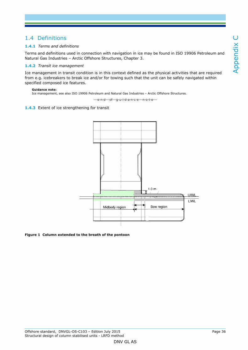
App
endi
x C
1.4 Definitions1.4.1 Terms and definitions
Terms and definitions used in connection with navigation in ice may be found in ISO 19906 Petroleum and Natural Gas Industries – Arctic Offshore Structures, Chapter 3.
1.4.2 Transit ice management
Ice management in transit condition is in this context defined as the physical activities that are required from e.g. icebreakers to break ice and/or for towing such that the unit can be safely navigated within specified composed ice features.
Guidance note:Ice management, see also ISO 19906 Petroleum and Natural Gas Industries – Arctic Offshore Structures.
---e-n-d---of---g-u-i-d-a-n-c-e---n-o-t-e---
1.4.3 Extent of ice strengthening for transit
Figure 1 Column extended to the breath of the pontoon
Offshore standard, DNVGL-OS-C103 – Edition July 2015 Page 36Structural design of column stabilised units - LRFD method
DNV GL AS

App
endi
x C
Figure 2 Column of round type
Figure 3 Column feature design
Offshore standard, DNVGL-OS-C103 – Edition July 2015 Page 37Structural design of column stabilised units - LRFD method
DNV GL AS

App
endi
x C
Figure 4 Ice belt for transit draft (shown for square columns extended to breath of pontoon)
1.4.4 Ice ride-down. In this context understood to be when ice is deflected downwards, especially when ice rubble has formed in front of columns and landing on top of pontoon.
1.4.5 Narrow pontoon freeboard (Tf). In this context used for column-stabilized units to describe the particularly low freeboard features of the pontoon in transit which may cause ice ride-down when navigating in waves.
1.4.6 Bracing air clearance is used in the context to describe the minimum clearance between the lowest transverse horizontal bracings and UIWL.
1.4.7 Inboard and outboard ice belt regions of the pontoons are used to describe and differentiate the ice belt in the midbody with respect to probability of hit. Inward midbody is normally the region in-between the pontoons.
1.4.8 The bow region is defined as the distance from the stem to a line parallel to and 0.04 L aft of the forward borderline of the part of the pontoon where the waterlines run parallel to the centreline. The overlap of the borderline does not need to exceed 5 m. For stems of pontoons of which the waterlines are mainly running parallel to the centerline, the bow region shall not be taken less than the distance from the stem to the first point of the column footing where the tangential at the point is running in parallel with the centerline of the pontoon. Fore of this column footing, the columns shall be reinforced at a height of 1m according strength criteria given in [2].
2 Ice design loads
2.1 Height of the ice load areaThe design ice height (h) for the respective ice classes shall be taken from DNV Rules for ships Pt.5 Ch.1 Sec.3.
2.2 Ice pressure 2.2.1 The design ice pressure (p) for ice belt regions of pontoons and columns facing ice shall be determined from DNV Rules for ships Pt.5 Ch.1 Sec.3 B201.
2.2.2 Design ice pressure (p) of areas falling outside the ice-belt, but which are considered prone to ice ride-down shall be particularly investigated by taking the kinematics of ice into consideration.
Guidance note:The ice design pressure (p) acting on the pontoon deck of the bow may, unless more precise data is available, be taken as:
ICE-T(1A): p = 1200 kN/m2
ICE-T(1B): p = 800 kN/m2
ICE-T(1C): p = 600 kN/m2
---e-n-d---of---g-u-i-d-a-n-c-e---n-o-t-e---
Offshore standard, DNVGL-OS-C103 – Edition July 2015 Page 38Structural design of column stabilised units - LRFD method
DNV GL AS

App
endi
x C
2.2.3 The value for C1 is given in Table 23 Shell plating
3.1 Vertical extension of ice strengthening for plating3.1.1 The vertical extension of the ice belt (see Figure 1 to Figure 4) shall not be less than given in Table 3.
3.2 Plate thickness in the ice belt3.2.1 Plate thickness for transverse and longitudinal framing for ice belt regions of pontoons and columns facing ice shall be determined from Rules for ships Pt.5 Ch.1 Sec.3 C200.
3.2.2 For areas of the pontoon deck exposed to ice ride-down in the bow region, the plate thickness may generally be determined as if transversely framed, irrespective of the actual stiffening direction of the deck.
3.2.3 Unstiffened plates of pontoons with shell radius:
In case the longitudinal stiffeners are positioned outside the curvature, R shall be substituted by R1 = R + 0.5 (a + b). The length a + b shall normally not exceed s/3, see Figure 5.
Table 2 Values of C1
Ice notation Bow 1) 2) Midbody 1) 2)
SternOutboard Inward
ICE-T(1A) 1.0 0.85 0.75 0.65
ICE-T(1B) 1.0 0.70 0.55 0.45ICE-T(1C) 1.0 0.50 0.35 0.251) Applicable for the exposed portion of the forward columns, see [1.4.3], when the minimum pontoon freeboard is less than 0.5m for
ICE-T(1A) and 0.4m for ICE-T(1B) and ICE-T(1C)2) ICE-T(1A), for portion of columns when pontoon freeboard: 0.5m ≤ Tf < 1.5 m; C1 = 1.17 - 0.35Tf
ICE-T (1B) and ICE-T(1A), for portion of columns when pontoon freeboard: 0.4m ≤ Tf < 1.5m; C1 = 1.20 - 0.5Tf
Table 3 Vertical extension of ice belt
Ice notation Region Above UIWL(m) Below LIWL (m)ICE-T(1A) Bow
See [1.4.3]0.90
MidbodyStern
0.75
ICE-T(1B) and ICE-T(1C)
BowSee [1.4.3]
0.70MidbodyStern
0.60
t 21.1 sf1 pPL⋅
σF----------------- tc mm( )+⋅ ⋅=
f1 1 .3 4.2h s⁄ 1.8+( )
-----------------------------– 1.0 0 .5 sR---–
maximum1.0,=
Offshore standard, DNVGL-OS-C103 – Edition July 2015 Page 39Structural design of column stabilised units - LRFD method
DNV GL AS
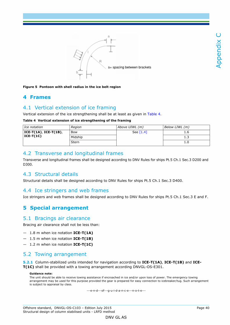
App
endi
x C
Figure 5 Pontoon with shell radius in the ice belt region
4 Frames
4.1 Vertical extension of ice framingVertical extension of the ice strengthening shall be at least as given in Table 4.
4.2 Transverse and longitudinal framesTransverse and longitudinal frames shall be designed according to DNV Rules for ships Pt.5 Ch.1 Sec.3 D200 and D300.
4.3 Structural detailsStructural details shall be designed according to DNV Rules for ships Pt.5 Ch.1 Sec.3 D400.
4.4 Ice stringers and web framesIce stringers and web frames shall be designed according to DNV Rules for ships Pt.5 Ch.1 Sec.3 E and F.
5 Special arrangement
5.1 Bracings air clearanceBracing air clearance shall not be less than:
— 1.8 m when ice notation ICE-T(1A)— 1.5 m when ice notation ICE-T(1B)— 1.2 m when ice notation ICE-T(1C)
5.2 Towing arrangement5.2.1 Column-stabilized units intended for navigation according to ICE-T(1A), ICE-T(1B) and ICE-T(1C) shall be provided with a towing arrangement according DNVGL-OS-E301.
Guidance note:The unit should be able to receive towing assistance if encroached in ice and/or upon loss of power. The emergency towing arrangement may be used for this purpose provided the gear is prepared for easy connection to icebreaker/tug. Such arrangement is subject to appraisal by class.
---e-n-d---of---g-u-i-d-a-n-c-e---n-o-t-e---
Table 4 Vertical extension of ice strengthening of the framing
Ice notation Region Above UIWL (m) Below LIWL (m)ICE-T(1A), ICE-T(1B),ICE-T(1C)
Bow See [1.4] 1.6Midship 1.3Stern 1.0
Offshore standard, DNVGL-OS-C103 – Edition July 2015 Page 40Structural design of column stabilised units - LRFD method
DNV GL AS

App
endi
x C
5.3 Equipment and structures mounted in ice-belt region5.3.1 Equipment mounted, or bracings landing in the ice-belt region, shall be protected against ice interaction, or be adequately designed to withstand the ice loads.
5.3.2 Structures, equipment and its supporting structures to the pontoon deck described in [5.3.1] shall be designed to withstand the ice loads as specified in Figure 6. Access manholes and other bolted openings in the ice belt region (e.g on top of pontoons and column shell) to tanks and other spaces shall not be permitted.
Figure 6 Equipment mounted on pontoon deck
Offshore standard, DNVGL-OS-C103 – Edition July 2015 Page 41Structural design of column stabilised units - LRFD method
DNV GL AS

SAF
DNV GLDriven by our purpose of safeguarding life, property and the environment, DNV GL enables organizations to advance the safety and sustainability of their business. We provide classification and technical assurance along with software and independent expert advisory services to the maritime, oil and gas, and energy industries. We also provide certification services to customers across a wide range of industries. Operating in more than 100 countries, our 16 000 professionals are dedicated to helping our customers make the world safer, smarter and greener.
ER, SMARTER, GREENER