Detection of Rare-Alleles and Their Carriers Using Compressed Se( que ) nsing

RULES FORCLASSIFICATION OF
SHIPS
SPECIAL SERVICE AND TYPEADDITIONAL CLASS
PART 5 CHAPTER 15
COMPRESSED NATURAL GAS CARRIERSJANUARY 2011
CONTENTS PAGE
Sec. 1 General Requirements.......................................................................................................... 5Sec. 2 Materials .............................................................................................................................. 9Sec. 3 Damage Stability and Ship Arrangements......................................................................... 10Sec. 4 Arrangements and Environmental Control in Hold Spaces............................................... 12Sec. 5 Scantling and Testing of Cargo Tanks .............................................................................. 13Sec. 6 Piping Systems in the Cargo Area ..................................................................................... 24Sec. 7 Overpressure Protection of the Cargo Tank and Cargo Piping System............................. 25Sec. 8 Gas-freeing of Cargo Containment System and Piping System ........................................ 26Sec. 9 Mechanical Ventilation in Cargo Area .............................................................................. 27Sec. 10 Fire Protection and Extinction ........................................................................................... 28Sec. 11 Electrical Installations........................................................................................................ 31Sec. 12 Control and Monitoring ..................................................................................................... 32Sec. 13 Tests after Installation........................................................................................................ 33Sec. 14 Filling Limits for Cargo Tanks .......................................................................................... 34Sec. 15 Gas Specification ............................................................................................................... 35Sec. 16 In Service Inspection.......................................................................................................... 36
DET NORSKE VERITASVeritasveien 1, NO-1322 Høvik, Norway Tel.: +47 67 57 99 00 Fax: +47 67 57 99 11
CHANGES IN THE RULES
GeneralThe present edition of the rules includes amendments and additions approved by the Executive Committee as of November2010 and supersedes the January 2008 edition of the same chapter.The rule changes come into force as described below.This chapter is valid until superseded by a revised chapter.
Main changes coming into force 1 July 2011• Sec.3 Damage Stability and Ship Arrangements— Items A301 and A305 have been amended.
• Sec.5 Scantling and Testing of Cargo Tanks— Item C102 has been rewritten and expanded in order to add an alternative procedure for fatigue calculations for CNG
tankers.— Item C701 has been rewritten in order to add an alternative procedure for fatigue calculations for CNG tankers.
Corrections and ClarificationsIn addition to the above stated rule requirements, a number of corrections and clarifications have been made to the existingrule text.
The electronic pdf version of this document found through http://www.dnv.com is the officially binding version© Det Norske Veritas
Any comments may be sent by e-mail to [email protected] subscription orders or information about subscription terms, please use [email protected] Typesetting (Adobe Frame Maker) by Det Norske Veritas
If any person suffers loss or damage which is proved to have been caused by any negligent act or omission of Det Norske Veritas, then Det Norske Veritas shall pay compensation tosuch person for his proved direct loss or damage. However, the compensation shall not exceed an amount equal to ten times the fee charged for the service in question, provided thatthe maximum compensation shall never exceed USD 2 million.In this provision "Det Norske Veritas" shall mean the Foundation Det Norske Veritas as well as all its subsidiaries, directors, officers, employees, agents and any other acting on behalfof Det Norske Veritas.

Rules for Ships, January 2011 Pt.5 Ch.15 Contents – Page 3
CONTENTS
Sec. 1 General Requirements ....................................................................................................................... 5
A. General ........................................................................................................................................................................... 5A 100 Application............................................................................................................................................................ 5A 200 Fundamental safety requirements ......................................................................................................................... 5A 300 Classification ........................................................................................................................................................ 6
B. Definitions ...................................................................................................................................................................... 6B 100 Terms .................................................................................................................................................................... 6
C. Documentation .............................................................................................................................................................. 7C 100 General.................................................................................................................................................................. 7C 200 Plans and particulars ............................................................................................................................................. 7
Sec. 2 Materials ............................................................................................................................................. 9
A. General ........................................................................................................................................................................... 9A 100 Materials ............................................................................................................................................................... 9A 200 Design temperature ............................................................................................................................................... 9
Sec. 3 Damage Stability and Ship Arrangements..................................................................................... 10
A. General ......................................................................................................................................................................... 10A 100 General................................................................................................................................................................ 10A 200 Divisions ............................................................................................................................................................. 10A 300 Collision and grounding...................................................................................................................................... 10A 400 Damage stability ................................................................................................................................................. 11
Sec. 4 Arrangements and Environmental Control in Hold Spaces ........................................................ 12
A. General ......................................................................................................................................................................... 12A 100 General ............................................................................................................................................................... 12A 200 Inerting of hold spaces ........................................................................................................................................ 12A 300 Overpressure protection of hold spaces .............................................................................................................. 12A 400 Drainage.............................................................................................................................................................. 12A 500 Area classification............................................................................................................................................... 12
Sec. 5 Scantling and Testing of Cargo Tanks .......................................................................................... 13
A. General ......................................................................................................................................................................... 13A 100 General................................................................................................................................................................ 13
B. Coiled Type Cargo Tank ............................................................................................................................................ 13B 100 General ............................................................................................................................................................... 13
C. Cylinder Type Cargo Tank ........................................................................................................................................ 13C 100 Cargo tank cylinder............................................................................................................................................. 13C 200 Cargo tank piping................................................................................................................................................ 16C 300 Welding requirements......................................................................................................................................... 16C 400 Pressure testing and tolerances ........................................................................................................................... 16C 500 Non-destructive testing (NDT) ........................................................................................................................... 16C 600 Post weld heat treatment ..................................................................................................................................... 16C 700 Prototype testing ................................................................................................................................................. 16
D. Composite Type Cargo Tank ..................................................................................................................................... 17D 100 General................................................................................................................................................................ 17D 200 Cargo tank cylinder - calculations ...................................................................................................................... 17D 300 Cargo tank piping................................................................................................................................................ 19D 400 Production requirements and testing after installation........................................................................................ 19D 500 Full scale prototype pressure testing and tolerances........................................................................................... 19D 600 Non-destructive testing (NDT) ........................................................................................................................... 21D 700 Composite - metal connector interface ............................................................................................................... 21D 800 Inner liner............................................................................................................................................................ 21D 900 Outer liner ........................................................................................................................................................... 23D 1000 Installation .......................................................................................................................................................... 23
Sec. 6 Piping Systems in the Cargo Area .................................................................................................. 24
A. General ......................................................................................................................................................................... 24A 100 Bilge, ballast fuel oil piping ............................................................................................................................... 24A 200 Cargo piping, General......................................................................................................................................... 24
DET NORSKE VERITAS

Rules for Ships, January 2011 Pt.5 Ch.15 Contents – Page 4
A 300 Cargo valves ....................................................................................................................................................... 24A 400 Cargo piping design ............................................................................................................................................ 24
Sec. 7 Overpressure Protection of the Cargo Tank and Cargo Piping System........................................................................................................................ 25
A. General ......................................................................................................................................................................... 25A 100 Cargo piping ....................................................................................................................................................... 25A 200 Cargo tanks ......................................................................................................................................................... 25
Sec. 8 Gas-freeing of Cargo Containment System and Piping System .................................................. 26
A. General ........................................................................................................................................................................ 26A 100 General................................................................................................................................................................ 26
Sec. 9 Mechanical Ventilation in Cargo Area........................................................................................... 27
A. General ......................................................................................................................................................................... 27A 100 General................................................................................................................................................................ 27A 200 Ventilation in hold spaces................................................................................................................................... 27
Sec. 10 Fire Protection and Extinction........................................................................................................ 28
A. General ........................................................................................................................................................................ 28A 100 General................................................................................................................................................................ 28A 200 Structural fire preventive measures .................................................................................................................... 28A 300 Means of escape.................................................................................................................................................. 29A 400 Firefighter’s outfit ............................................................................................................................................... 29A 500 Fire main ............................................................................................................................................................. 29A 600 Dual agent (water and powder) for process and load/unload area...................................................................... 29A 700 Water spray ......................................................................................................................................................... 30A 800 Spark arrestors .................................................................................................................................................... 30
Sec. 11 Electrical Installations ..................................................................................................................... 31
A. General ......................................................................................................................................................................... 31A 100 General................................................................................................................................................................ 31
Sec. 12 Control and Monitoring................................................................................................................... 32
A. General ......................................................................................................................................................................... 32A 100 General................................................................................................................................................................ 32
Sec. 13 Tests after Installation ..................................................................................................................... 33
A. General ......................................................................................................................................................................... 33A 100 General................................................................................................................................................................ 33
Sec. 14 Filling Limits for Cargo Tanks ....................................................................................................... 34
A. General ......................................................................................................................................................................... 34A 100 General................................................................................................................................................................ 34
Sec. 15 Gas Specification .............................................................................................................................. 35
A. General ......................................................................................................................................................................... 35A 100 General................................................................................................................................................................ 35
Sec. 16 In Service Inspection........................................................................................................................ 36
A. General ......................................................................................................................................................................... 36A 100 General................................................................................................................................................................ 36
DET NORSKE VERITAS

Rules for Ships, January 2011 Pt.5 Ch.15 Sec.1 – Page 5
SECTION 1 GENERAL REQUIREMENTS
A. GeneralA 100 Application101 The rules in this chapter apply to ships engaged in the transportation of compressed natural gases (CNG).For liquefied gas carriers reference is made to Ch.5.102 The vessel must be accepted by the flag state and the respective port authorities.
A 200 Fundamental safety requirements201 The overall safety with respect to life, property and environment shall be equivalent or better thancomparable LNG vessels built and operated according to traditional ship rules and industry practices.
202 For new concepts a Quantitative Risk Assessment (QRA) shall be submitted as a part of the classificationdocumentation. The QRA shall comply with the principles for safety assessment outlined in e.g. IMO ReportMSC 72/16. For new concepts or modifications to existing systems a Hazard Identification (HAZID)/HazardOperability Study (HAZOP) of the cargo tank, cargo piping, process system, operational procedures etc. shallbe submitted for information.203 The fundamental safety requirements shall take into consideration safety targets for:
— life (crew and third party personnel)— property (damage to ship, off-hire)— environment (oil pollution, gas release to the atmosphere).
204 The safety level on a LNG carrier represents the minimum acceptable safety level for a CNG vessel. Thetargets shall therefore be based on historical experience and as shown in Table A1.
In addition, the As Low As Reasonably Practicable (ALARP) principle shall be adopted as a safety philosophyto ensure:
— focused and continuous safety efforts— that the overall (and absolute) targets are not misused to argue that sound safety measures are not
implemented.
Guidance note:ALARP is applied on a project specific basis and applies the principles that:- Intolerable risk cannot be justified and the vessel cannot be built or continue to operate.- Where the risk is below this level but higher than the broadly acceptable risk, then the risk is tolerable provided
that the risk is ALARP, i.e. further risk reduction is impracticable or its cost is grossly disproportional to the riskimprovement gained. This means that the owner or operator shall take all reasonably practicable precautions toreduce the risk, either by ensuring the faults do not occur, or that if they do then their consequences are not serious.
- In the broadly acceptable region, the risk is so low that further risk assessment or consideration of additionalprecautions is unnecessary.
---e-n-d---of---G-u-i-d-a-n-c-e---n-o-t-e---
Table A1 Safety target values for CNG carriers (annual risk)Historical 1) data LNG
Target Safety Values for CNG Comment
Individual risk for crew members (due to major accidents)
1.2 × 10⁻⁴ 1 × 10⁻⁴Does not include occupational risks and work place accidents
Total loss due to collision 1.2 × 10⁻⁴ 1 × 10⁻⁴ Total loss frequency– generic LNG vessel
Total loss due to cargo hazards (fires and explosions) 2.4 × 10⁻⁴ 1 × 10⁻⁴ Total loss frequency
– generic LNG vesselIndividual risk from cargo cylinder failure 1 × 10⁻⁵ Safety Class High, DNV-OS-F101
Individual risks for public ashore 1 × 10⁻⁵ IMO MSC 72/16 Annex 11) The historical data for LNG vessels has been taken from DNV Technical Report No. 2001-0858.
DET NORSKE VERITAS

Rules for Ships, January 2011 Pt.5 Ch.15 Sec.1 – Page 6
A 300 Classification
301 The requirements in this chapter are supplementary to those for assignment of main class. Ships builtaccording to these rules may be assigned the class notation 1A1 Tanker for Compressed Natural Gas.The following special features notations will be stated in the register of vessels classed with DNV: (... bar,..temp), which refers to the design pressure and minimum operating temperature. In the case of carriage of thegas in the chilled condition the carriage temperature will be stated. If no chilling is provided ambienttemperature will be stated.
302 Ships having offshore loading arrangements shall comply with the requirements in Ch.3 Sec.14.
303 The process plant, relief and flare system shall be designed according to a standard recognised by theSociety.
B. Definitions
B 100 Terms
101 Blow down is depressurising or disposal of an inventory of pressurised gas.
102 Cargo area is that part of the ship which contains the cargo tanks, hold spaces, process area, turret spaceand cofferdams and includes deck areas over the full length and breadth of the part of the ship over the above-mentioned spaces.
103 Cargo hold vent pipes are low pressure pipes for venting of cargo hold spaces to vent mast.
104 Cargo load/unload valve is the valve isolating the cargo piping from external piping.
105 Cargo piping is the piping between the cargo tank valve and the cargo load and or unload valve.
106 Cargo tank consists of the storage system for the compressed gas, i.e. all pressurised equipment up to thecargo tank valve.
107 Cargo tank valve isolates the cargo tank from the cargo piping.
108 Cargo vent piping is the piping from the cargo relief valve to the vent mast.
109 “Class H fire division”: divisions formed by bulkheads and decks. See Sec.10 A207.
110 Coiled type cargo tank is a cargo tank consisting of long lengths of small diameter coiled piping.
111 Cylinder type cargo tank is a cargo tank consisting of an array of cylinder type pressure vesselsconnected by cargo tank piping. The following definitions are relevant for the cylinder type tank:
— Cargo tank cylinder is a large diameter standard offshore pipe with end-caps constituting the main tankvolume.
— Cargo tank piping is the piping connecting the cargo tank cylinders up to the cargo tank valve.
112 The following pressure definitions are used:
— design pressure is the maximum gauge gas pressure at the top of the cargo tank which has been used in thecalculation of the scantlings of the cargo tank and cargo piping. Design pressure defined in these rules is synonymous with “incidental pressure” as used in DNV–OS-F101.
— maximum allowable operating pressure is 95% of the design pressure.— set pressure of pressure relief system, the design pressure less the tolerance of the pressure relief system.
113 Design temperature for the selection of materials in cargo tanks, piping, supporting structure and innerhull structure is the lowest or highest temperature which can occur in the respective components. Reference ismade to Sec.2 A200.
114 Regarding the definitions of gas dangerous area and zones the principles of Ch.5 Sec.1 applies. Theextension of the gas dangerous zones shall be re-evaluated taking into account high pressure relief sources andnew equipment. IEC-92 may be used for guidance in evaluating the extent of the zones.
115 Hold space is the space enclosed by the ship's structure in which a cargo tank is situated.
116 Hold space cover is the enclosure of hold space above main deck ensuring controlled environmentalconditions within hold space.
DET NORSKE VERITAS

Rules for Ships, January 2011 Pt.5 Ch.15 Sec.1 – Page 7
C. Documentation
C 100 General101 200 specifies the plans and particulars that shall normally be submitted. The drawings shall show clearlythat the requirements of this chapter have been fulfilled.102 Other plans, specifications or information may be required depending on the arrangement and theequipment used in each separate case.103 For general requirements for documentation of control and monitoring systems, see Pt.4 Ch.9 Sec.1.
C 200 Plans and particulars201 General safety documentation shall be submitted for information:
— for new concepts a Quantitative Risk Assessment (QRA) shall be submitted as a part of the classificationdocumentation. The QRA shall comply with the principles for Formal Safety Assessment outlined in IMOReport MSC 72/16 and 74/19
— for new concepts or modifications to existing systems a Hazard Identification (HAZID)/Hazard andOperability Study (HAZOP) of the cargo system, process system (if applicable), operational proceduresetc. shall be submitted for information.
202 A general arrangement shall be submitted for approval giving the locations of:
— machinery spaces, accommodation, service and control station spaces, chain lockers, cofferdams, fuel oiltanks, drinking and domestic water tanks and stores
— cargo tanks and cargo piping systems— cargo control rooms— cargo piping with shore or offshore connections including loading and discharge arrangements and
emergency cargo dumping arrangement, if fitted— ventilating pipes, doors and openings to gas-dangerous spaces— doors, air locks, hatches, ventilating pipes and openings, hinged scuttles which can be opened, and other
openings to gas-safe spaces within and adjacent to the cargo area— entrances, air inlets and openings to accommodation, service and control station spaces— gas-safe spaces and zones and gas-dangerous spaces and zones to be clearly identified. If cold venting a gas
dispersion analysis shall be conducted in order to evaluate the extent of the gas dangerous area— information on gas specification to be carried on the ship— drawings showing ventilation systems in cargo area with capacities.
203 Cargo tank. The following plans and particulars shall be submitted for approval:
— drawing of tanks with information on non-destructive testing of welds and strength and tightness testing oftanks
— specification of materials and welding in cargo tanks — specification of design loads and structural analysis of cargo tanks — detailed arrangement of cargo tank system with description on operation modes— calculation of maximum and minimum design temperature for materials in the cargo tank, supporting
structure and inner hull due to loading/unloading/depressurising— the cooling effect from gas released as a result of a leakage or rupture of piping— proposal for prototype testing with full scale fatigue and burst test for cargo tank— drawings and calculation of stresses in the cargo tank piping as per Ch.5 Sec.6 including vibrations and
fatigue analysis— fatigue crack propagation calculations for the cargo tank piping using leak-before-failure principle— detailed drawings of all pressurised parts of the cargo tank system— documentation and calculations for hull and cargo tank using model tests, refined analytical tools and
analysis methods to determine stress levels, fatigue life and crack propagation characteristics. Vibrationanalysis as outlined in Ch.5 Sec.5
— stresses in the cargo tank cylinders as per DNV-OS-F101 for safety class high— fatigue analysis for cylinders as per DNV-OS-F101 and in agreement with criteria that will be specified by
DNV — relevant fatigue crack propagation calculations for cargo tank cylinders in agreement with criteria that will
be specified by DNV— drawings of supports for cargo tank cylinders with calculations including collision loads defined in Ch.5
sec.5.
204 Piping systems in cargo area. The following plans and particulars shall be submitted for approval:
— schematic drawings with materials, fittings and thickness for the following piping systems:
DET NORSKE VERITAS
Rules for Ships, January 2011 Pt.5 Ch.15 Sec.1 – Page 8
— bilge and ballast systems and air pipes— cargo deck piping— emergency shut down— inert gas— heating, if any— systems for refrigeration, if any
— a complete stress analysis for each branch of the cargo deck piping system shall be conducted according toANSI/ASME B31.3
— operational and emergency procedures for possible incidents in the cargo tank— drawings showing overpressure protection for cargo tank, including details of pressure relief devices— arrangements and procedure for gas freeing — arrangements for mechanical ventilation in cargo area— specification of pressure tests.
205 Damage stability and ship arrangements. The following plans and particulars shall be submitted forapproval:
— drawing showing protection of cargo tank system with double hull and minimum distance to ship bottom— raking damage calculations, showing that the maximum ship speed, at which the extent of raking damage
will not penetrate into the forward cargo hold space, is sufficient for safe manoeuvring of the ship at notless than 5 knots
— collision damage analysis which demonstrates that the energy absorption capability of the ship side issufficient to prevent the bow of the striking vessel(s) from penetrating the inner hull as defined in Sec.3A302 and A303
— damage stability requirements of Chapter 2 of the International Code for the construction and equipmentof ships carrying liquefied gases in bulk for ship type 2G.
206 Environmental control in hold spaces. The following plans and particulars shall be submitted forapproval:
— an inspection plan shall be developed and submitted for approval. The plan shall include a detaileddescription on how safe access for inspection is provided
— drawings showing the following:
— inerting of cargo hold space— instrumentation in hold spaces— drainage in hold spaces— overpressure protection.
207 Fire protection and extinction. The following plans and particulars shall be submitted for approval:
— for new concepts documentation of fire loads based on risk analysis and fire and explosion analysis— drawings showing means of escape — fire fighting systems drawings related to cargo area including fire mains, sprinkler and water spray and
water and or powder systems— heat radiation from the flare towards cargo holds and other important areas and equipment.
208 Electrical Installations
— drawings as per Ch.5 Sec.12, as applicable.
209 Control and Monitoring
— drawings as per Ch.5 Sec.13.
210 In- service inspection
— in-service inspection and monitoring philosophy.
211 Reference documents are the latest version of:
— Ch.5, Pt.2, Pt.3 and Pt.4— DNV-OS-F101 Submarine Pipeline Systems— International Code for the Construction and Equipment of Ships Carrying Liquefied Gases in Bulk, IGC
Code— ASME VIII Div.2 - ASME Boiler and Pressure Vessel Code - Alternative Rules for Pressure Vessels— ASME B31.3 - Process Piping— API RP521 - Guide for Pressure Relieving and Depressurizing Systems— DNV-OS-C501 - Composite Components.
DET NORSKE VERITAS

Rules for Ships, January 2011 Pt.5 Ch.15 Sec.2 – Page 9
SECTION 2 MATERIALS
A. GeneralA 100 Materials101 The materials used in the hull structure shall comply with the requirements for manufacture, survey andcertification given in Pt.2 and Pt.3 Ch.1.102 For the cylinder type cargo tank the materials used in the cylinder and end-caps shall comply with therequirements for manufacture, survey and certification given in DNV-OS-F101. Due regard shall be given tocorrosion protection.
Guidance note:The use of suitable protective coating or liners can be an acceptable means of corrosion protection.
---e-n-d---of---G-u-i-d-a-n-c-e---n-o-t-e---
103 For the coiled type cargo tank the materials used shall comply with the requirements for manufacture,survey and certification given in DNV-OS-F101 or a recognised standard acceptable to DNV.104 The materials used in the cargo tank piping, cargo piping and all valves and fittings shall be of qualityNV 316L or equivalent (equivalent with respect to ductility, fatigue and corrosion resistance) and shall complywith the requirements for manufacture survey and certification given in Pt.2 and Ch.5.
Guidance note:Unprotected piping on open deck is recommended to be painted.
---e-n-d---of---G-u-i-d-a-n-c-e---n-o-t-e---
105 Cargo hold vent pipes shall be of a fire resistant material capable of withstanding the calculated pressure.106 Composite materials will be specially considered. Composite material used in cargo tanks shall complywith Sec.5 D.107 All material used in the cargo tank and cargo piping shall be provided with DNV material certificate.
A 200 Design temperature201 The maximum design temperature for selection of materials is the highest temperature which can occurin the cargo tanks or cargo piping due to:
— loading/transport/unloading.
202 The minimum design temperature for the selection of materials is the lowest temperature which canoccur in the cargo tanks, cargo piping, supporting structure or inner hull due to:
— loading/transport/unloading.— the cooling effect from accidental release of cargo gas.
When determining the minimum design temperature the cooling effects from an accidental release inside thecargo holds shall be documented. The documentation shall address:
— a leakage or complete rupture of the cargo tank piping at one location for the cylinder type system— the cooling effect from the complete rupture of one pipe in the coil for the coiled system.
Partial protective boundaries shall be provided to prevent direct cooling down of tank units or of ship'sstructure. Ambient temperatures for calculating the above steel temperatures shall be 5°C for air and 0°C forsea water unless other values are specified for special areas.
DET NORSKE VERITAS

Rules for Ships, January 2011 Pt.5 Ch.15 Sec.3 – Page 10
SECTION 3 DAMAGE STABILITY AND SHIP ARRANGEMENTS
A. GeneralA 100 General101 The ship shall meet the requirements given in Ch.5 Sec.3. In addition the below requirements applies.102 A CNG ship shall be of a double hull construction with double sides and double bottom.Equivalent bottom solutions may be used if they can be shown by calculations or tests to offer the sameprotection to the cargo tank against indentations and the same energy absorption capabilities as conventionaldouble bottom design. (See raking damage calculations in A301.)
A 200 Divisions201 The cargo holds shall be segregated from engine rooms and accommodation spaces and similar spaces,by cofferdams.
A 300 Collision and grounding301 For conventional double bottom designs the double bottom height shall at least be B/15 or 3 m whicheveris less, but not less than 1.0 m.A safe maximum navigating speed where by the cargo tank or its supports are not damaged by grounding on arocky seabed, shall be determined by grounding raking damage calculations. The maximum navigating speedshall be equal to or larger than the minimum safe manoeuvring speed of the vessel. For the purpose of thesecalculations this speed shall not be taken to be less than 5 knots.
Guidance note:For grounding raking damage calculations a triangular shaped rock with a width of twice the penetrating height maybe used.
---e-n-d---of---G-u-i-d-a-n-c-e---n-o-t-e---
302 A collision frequency analysis shall, for new projects, be conducted for a characteristic vessel trade. Theanalysis shall determine the annual collision frequency and associated collision energies of striking vessels,based on vessel sizes, types and speeds determined from traffic data for the selected trade. If applicable trafficdata for the actual trade is not available, or no specific trade rather than world-wide trading is planned, relevanttraffic data for North Sea trading acceptable to the Society may be used. 303 Collision damage analysis shall be conducted to demonstrate that:
— For the ship sizes and energies determined in 302 the energy absorption capability of the ship side shall besufficient to prevent the bow of the striking vessel(s) from penetrating the inner hull, thus not damaging thecargo tanks.Alternatively:For the purpose of the calculations it may conservatively be assumed that all the collision energy will beabsorbed by the struck ship side. Hence, the following simplifications will be accepted:
— the use of an infinitely stiff striking bow— hit perpendicular to the ship side and no rotation of struck ship— no common velocity of the two ships after collision
In lieu of more specific information a 5000 tonnes standard supply vessel with a raking bow and a stemangle of 65 degrees may be used. It shall be demonstrated by calculations that the side of the CNG carrierhas an energy absorption capability according to 302, but not less than given by the formula in 304 withoutthe bow penetrating the inner hull.
304 The minimum collision energy to be absorbed in the collision shall be taken as:max. [13 (Lpp / 100)2 / (1 + 0.8 Δ1 / ΔCNG); 10] [MJ]
Lpp = length between perpendiculars of the CNG vessel in (m) Δ1 = the displacement of the average size of the population of striking vessels which can be taken as 10000
tonsΔCNG = the displacement of the struck CNG vessel. 305 For conventional double side designs the width of the double side shall at least be minimum B/15 or 2 mwhichever is the greater.
DET NORSKE VERITAS
Rules for Ships, January 2011 Pt.5 Ch.15 Sec.3 – Page 11
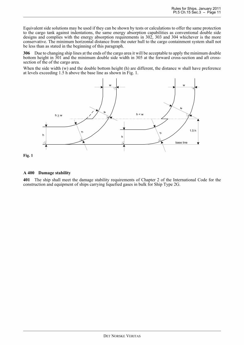
Equivalent side solutions may be used if they can be shown by tests or calculations to offer the same protectionto the cargo tank against indentations, the same energy absorption capabilities as conventional double sidedesigns and complies with the energy absorption requirements in 302, 303 and 304 whichever is the moreconservative. The minimum horizontal distance from the outer hull to the cargo containment system shall notbe less than as stated in the beginning of this paragraph.306 Due to changing ship lines at the ends of the cargo area it will be acceptable to apply the minimum doublebottom height in 301 and the minimum double side width in 305 at the forward cross-section and aft cross-section of the of the cargo area.When the side width (w) and the double bottom height (h) are different, the distance w shall have preferenceat levels exceeding 1.5 h above the base line as shown in Fig. 1.
Fig. 1
A 400 Damage stability401 The ship shall meet the damage stability requirements of Chapter 2 of the International Code for theconstruction and equipment of ships carrying liquefied gases in bulk for Ship Type 2G.
h > w
hh
hh
h < w
1.5 h
base line
w
w
w
w
DET NORSKE VERITAS

Rules for Ships, January 2011 Pt.5 Ch.15 Sec.4 – Page 12
SECTION 4 ARRANGEMENTS AND ENVIRONMENTAL CONTROL IN HOLD SPACES
A. General
A 100 General 101 The principles for access for inspection given in Ch.5 Sec.4 A shall be used where visual inspection isrequired. For the cylinder type cargo tank access for inspection of cargo tank cylinders, supports, foundationsand cargo tank piping shall be arranged from outside the cylinders. For the coiled type cargo tank a method forinspection from inside by use of special inspection tools shall be predetermined. 102 An inspection plan shall be developed and submitted for approval. The plan shall include a detaileddescription on how safe access for inspection is provided.103 The cargo tank valve shall be mounted outside the hold space.For enclosed hold spaces the provisions in A200 and A300 apply.
Guidance note:Cargo tanks may be located in enclosed or open hold spaces.
---e-n-d---of---G-u-i-d-a-n-c-e---n-o-t-e---
104 For open hold spaces special attention shall be given to corrosion protection and fire protection of thecargo tanks and the possibility for detecting a leak within the cargo area.
A 200 Inerting of hold spaces201 The hold space shall be inerted with nitrogen or inerted with other suitable non corrosive medium. Thenitrogen supply system shall be arranged to prevent back flow in the case of overpressure in hold space. Thenitrogen system shall be designed with redundancy to the extent necessary for maintaining the safe operationof the vessel.
202 For composite cargo tanks the hold space is to be enclosed and inerted.The atmosphere in the hold space is to be purged with nitrogen or other suitable inert gas and the concentrationis to be kept under 0.3LEL (Lower Explosion Limit).
A 300 Overpressure protection of hold spaces301 Hold space shall be fitted with a overpressure protection system. The following functional requirementsapply:
a) Pressure control of inerted atmosphere with positive pressure automatically adjusted between 0.05 and 0.15bar above atmospheric pressure shall be provided.
b) Pressure relief device, normally set to open at 0.25 bar, shall be provided. The relief device shall havesufficient capacity to handle a rupture of the largest cargo tank piping in the hold space for the cylinder typecargo tank and a rupture of one pipe in the coil for the coiled type cargo tank. This applies to the largestcargo tank in the relevant hold space.
c) The discharge from the hold spaces shall be routed to a safe location.d) In addition to the relief system required by b) relief hatches, normally set to open at 0.4 bar shall be
provided in each hold space cover.e) It shall be demonstrated that the pressure protection devices and their surrounding structures are capable of
handling the lowest temperature achieved during pressure relieving at maximum capacity.
A 400 Drainage401 Hold spaces shall be provided with a suitable drainage arrangement not connected with machineryspaces. Means for detecting leakage of water into the hold space shall be provided.
A 500 Area classification501 The extent of gas dangerous zones and gas dangerous spaces shall follow the principles in Pt.5 Ch.5.502 If cold venting is used for the gas relief system a gas dispersion analysis shall be conducted in order toevaluate the extent of the gas dangerous zone. The analyses shall be carried out according to a recognisedstandard/software and the boundaries of the gas dangerous zone shall be based on 50% LEL (Lower ExplosionLimit) concentration.
DET NORSKE VERITAS

Rules for Ships, January 2011 Pt.5 Ch.15 Sec.5 – Page 13
SECTION 5 SCANTLING AND TESTING OF CARGO TANKS
A. GeneralA 100 General101 The cargo tank shall be designed using model tests, refined analytical tools and analysis methods todetermine stress levels, fatigue life and crack propagation characteristics. Changes to material properties withtime due to long term static loads and the environment shall also be considered for composites. 102 The cargo tank together with supports and other fixtures shall be designed taking into account all relevantloads listed in Ch.5 Sec.5 A. 103 The dynamic loads due to ship motions shall be taken as the most probable largest loads the ship willencounter during its operating life (normally taken to correspond to a probability level of 10-8 in the North Atlantic).Loading rates shall be considered for composites, since these materials have rate dependent properties.104 The dynamic effect of pressure variations due to loading and unloading shall represent the extreme serviceconditions the containment system will be exposed to during the lifetime of the ship. As a minimum the designnumber of pressure cycles from maximum pressure to minimum pressure shall not be less than 50 per year.105 Vibration analysis shall be carried out as outlined in Ch.5 Sec.5.106 Transient thermal loads during loading and unloading shall be considered.107 The effects of all dynamic and static loads shall be used to determine the strength of the structure withrespect to:
— maximum allowable stresses— buckling— cyclic and static fatigue failure— crack propagation.
108 For cargo tank types other than coiled type and cylinder type, the requirements for cylinder type tanksgiven in C applies, as relevant.109 Process prototype testing shall be carried out to document that the system functions as specified withrespect to accumulation and disposal of liquids. It shall be verified that liquid hammering does not occur in thepiping system during any operation.Where it is impractical to perform full scale testing, successful operation can be simulated computationally andin small scale testing to provide adequate assurance of functionality. Commissioning and start-up testing shallbe witnessed by a surveyor and is considered complete when all systems, equipment and instrumentation areoperating satisfactorily.
B. Coiled Type Cargo TankB 100 General 101 Requirements for the coiled type cargo tank shall be especially considered. The requirements applicablefor the cylinder type cargo tank shall be complied with, as found relevant.
C. Cylinder Type Cargo TankC 100 Cargo tank cylinder101 The stresses in the cargo cylinder and the hemispherical end caps shall fulfil the requirements given inDNV-OS-F101 for safety class high. Recognised standards such as the ASME BPV VIII Div. 3 may also beused. The pressure used for calculating the wall thicknesses is the design pressure defined in Sec.1 B112. Themaximum operating pressure shall be 5% or more below the design pressure. Hemispherical ends shall have acylindrical extension (skirt) so that the distance to the circumferential weld to the cylinder is not less than:
R = radius of hemispherical endt = thickness of hemispherical end.For elliptical or torispherical end-caps additional requirements may apply subject to agreement with DNV.
1.0 Rt
DET NORSKE VERITAS

Rules for Ships, January 2011 Pt.5 Ch.15 Sec.5 – Page 14
102 The cargo tank cylinder shall be subject to fatigue analysis. The S-N curve shall be applicable for thematerial, the construction detail and the state of stress in question. Model testing of cargo tank details asfabricated is required to establish the curve.
Guidance note:The test specimens can be either coupon tests or full ring test specimens cut from fabricated pipes at the actualproduction line. Normally, ring tests will provide the more realistic results.
---e-n-d---of---G-u-i-d-a-n-c-e---n-o-t-e---
Two alternative formulations are given based on the following definitions of characteristic value for log10Nfor the system of ns cylinders:
1) Mean value minus 3 standard deviations (μ-3σ) and no further adjustment2) Mean value minus 2 standard deviations (μ-2σ), supplemented with a system effect term
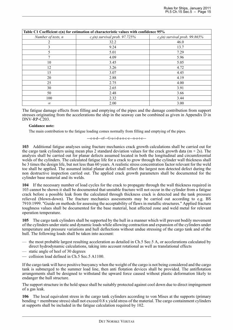
The two formulations for the estimate of the characteristic value of log10N for the system of ns cylinders arecorrespondingly denoted as Alternative 1 and Alternative 2:Alternative 1: The characteristic S-N curve for use in design is defined as the "mean-minus-three-standard-deviations" curveas obtained from a log10S-log10N plot of experimental data. With a Gaussian assumption for the residuals inlog10N with respect to the mean curve through the data, this corresponds to a curve with 99.865% survivalprobability. The uncertainty in this curve when its derivation is based on a limited number of test data shall beaccounted for. It is required that the characteristic curve be estimated with at least 95% confidence. When atotal of n observations of the number of cycles to failure N are available from n fatigue tests carried out at thesame representative stress range S, then the characteristic value of log10N at this stress level is to be taken as:
in which is the mean value of the n observed values of log10N, is the standard deviationof the n observed values of log10N, and c3(n) is a factor whose value depends on n and is tabulated in Table C1. The Miner sum (for both dynamic ship loads and fatigue loads due to loading and unloading) is not to be higherthan 0.1 (i.e. using a Design Fatigue Factor DFF=10). The minimum calculated fatigue life using theAlternative 1 S-N curve approach shall not be less than 200 years.Alternative 2:takes system information into account and provides an estimate of the characteristic value of log10N for thesystem based on "mean value minus two standard deviations" of the test data.
wherec2(n) = factor whose value depends on n and is tabulated in Table C1 corresponding to a 97.725% probability
of survival. It is noted that for =0.20, the expression for the characteristic value of log10N for thesystem is identical to the expression for the S-N curve with system effects given in DNV-RP-C203for traditional offshore applications.
lweld = length of weld subjected to the same stress range (typical length of one cylinder)lref = reference weld length with similar weld quality and fatigue strength as the tested specimen. lref = 120
mm may be used if not otherwise documented by fatigue testing.ns = number of similar connections subjected to the same stress range (typical number of cylinders).The number of load cycles to be used for design is number of cycles expected during design life multiplied bya Design Fatigue Factor (DFF) in order to achieve an appropriate safety level. The Miner sum (for both dynamic ship loads and fatigue loads due to loading and unloading) is not to be higher than
1) 0.2 (DFF=5) for pipes with enhanced control in fabrication with respect to production tolerances and whereout-of-roundness has not been specifically considered in the design of the longitudinal welds.
2) 0.33 (DFF=3) at areas with local high stresses such as at pipe supports provided that all local stresses areaccounted for in the analyses together with the S-N curves in DNV-RP-C203.
The minimum calculated fatigue life using the Alternative 2 S/N curve approach shall not be less than 20×DFF years.
Nc ncNN log31010 ˆ)(loglog σ⋅−=N10log Nlogσ̂
σ̂))(log21)((logˆlog 10210,10 ⋅⋅⋅+−= s
ref
weldsystemC n
llncNN
σ̂
DET NORSKE VERITAS
Rules for Ships, January 2011 Pt.5 Ch.15 Sec.5 – Page 15
The fatigue damage effects from filling and emptying of the pipes and the damage contribution from supportstresses originating from the accelerations the ship in the seaway can be combined as given in Appendix D inDNV-RP-C203.
Guidance note:The main contribution to the fatigue loading comes normally from filling and emptying of the pipes.
---e-n-d---of---G-u-i-d-a-n-c-e---n-o-t-e---
103 Additional fatigue analyses using fracture mechanics crack growth calculations shall be carried out forthe cargo tank cylinders using mean plus 2 standard deviation values for the crack growth data (m + 2s). Theanalysis shall be carried out for planar defects assumed located in both the longitudinal and circumferentialwelds of the cylinders. The calculated fatigue life for a crack to grow through the cylinder wall thickness shallbe 3 times the design life, but not less than 60 years. A realistic stress concentration factor relevant for the weldtoe shall be applied. The assumed initial planar defect shall reflect the largest non detected defect during thenon destructive inspection carried out. The applied crack growth parameters shall be documented for thecylinder base material and its welds.
104 If the necessary number of load cycles for the crack to propagate through the wall thickness required in103 cannot be shown it shall be documented that unstable fracture will not occur in the cylinder from a fatiguecrack before a possible leak from the calculated through thickness crack is detected and the tank pressurerelieved (blown-down). The fracture mechanics assessments may be carried out according to e.g. BS7910:1999. "Guide on methods for assessing the acceptability of flaws in metallic structures." Applied fracturetoughness values shall be documented for the base material, heat affected zone and weld metal for relevantoperation temperature.
105 The cargo tank cylinders shall be supported by the hull in a manner which will prevent bodily movementof the cylinders under static and dynamic loads while allowing contraction and expansion of the cylinders undertemperature and pressure variations and hull deflections without undue stressing of the cargo tank and of thehull. The following loads shall be taken into account:
— the most probable largest resulting acceleration as detailed in Ch.5 Sec.5 A, or accelerations calculated bydirect hydrodynamic calculations, taking into account rotational as well as translational effects
— static angle of heel of 30 degrees— collision load defined in Ch.5 Sec.5 A1100.
If the cargo tank will have positive buoyancy when the weight of the cargo is not being considered and the cargotank is submerged to the summer load line, then anti flotation devices shall be provided. The antiflotationarrangements shall be designed to withstand the upward force caused without plastic deformation likely toendanger the hull structure.The support structure in the hold space shall be suitably protected against cool down due to direct impingementof a gas leak.
106 The local equivalent stress in the cargo tank cylinders according to von Mises at the supports (primarybending + membrane stress) shall not exceed 0.8 x yield stress of the material. The cargo containment cylindersat supports shall be included in the fatigue calculation required by 102.
Table C1 Coefficient c(n) for estimation of characteristic values with confidence 95%Number of tests, n c2(n) survival prob. 97.725% c3(n) survival prob. 99.865%
2 32.2 46.03 9.24 13.75 5.01 7.297 4.09 5.9610 3.45 5.0512 3.26 4.7215 3.07 4.4520 2.88 4.1925 2.75 4.0030 2.65 3.9150 2.48 3.66
100 2.32 3.44∞ 2.00 3.00
DET NORSKE VERITAS

Rules for Ships, January 2011 Pt.5 Ch.15 Sec.5 – Page 16
C 200 Cargo tank piping201 The stresses in the cargo tank piping shall fulfil the requirements given in Ch.5 Sec.6. The stresscalculation shall include all relevant loads given above including vibrations. The calculation of maximumstresses and stress range may be carried out according to ASME B31.3. The design principles given in Sec.6A400 applies also for the cargo tank piping.202 The cargo tank piping shall be subject to a fatigue analysis. The S-N curve shall be applicable for thematerial, construction detail and state of stress considered. Model testing of details of piping as fabricated maybe required. The S-N curve shall be based on the mean curve of log10N with the subtraction of 2 standarddeviations log10N. The Miner sum (from combined dynamic loads and fatigue loads due to loading andunloading) shall not be higher than 0.1.203 Fatigue crack propagation calculations shall be carried out for the cargo tank piping. The analysis shallbe carried out for defects assumed located in circumferential welds only as the piping shall be of a seamlesstype or equivalent. The leak-before-failure principle shall be used, i.e. a crack shall propagate through thethickness allowing gas detection and safe blow-down or venting of the affected cargo tank before a completerupture takes place. Design criteria as for 103 apply. 204 The cargo tank piping shall be adequately supported so that the reaction force from a complete ruptureof a top pipe will not lead to the rupture of other pipes by the damaged pipe hitting other pipes. At the sametime sufficient flexibility shall be provided in order to allow the cylinders to expand due to pressure andhorizontally movement of the cylinder nozzle due to accelerations and vibrations without causing excessivestresses in the piping system which might lead to yielding or fatigue problems. Cargo tank piping up to thecargo tank valve shall be of all welded construction.205 All fittings in the cargo tank piping shall be of forged type. Alternative solutions may be considered bythe Society.
C 300 Welding requirements301 Welding procedure qualification. Pre-production weldability testing shall be carried out for qualification of the tank material and weldingconsumable according to a weldability testing programme including bead on plate, Y-groove and also fracturetoughness tests of base material, HAZ and weld metal. Metallographic examination shall be conducted toestablish the presence of local brittle zones. The maximum and minimum heat inputs giving acceptableproperties in the weld zones with corresponding preheat temperature, working temperatures and post weld heattreatment temperatures (if post weld heat treatment required) shall be determined for both fabrication andinstallation welding. The testing programme for the cargo tank cylinder shall be in accordance with DNV-OS-F-101. Relevant documentation may be agreed in lieu of weldability testing. Fracture mechanics testing at theminimum design temperature shall, however, be performed for the base material, heat affected zone and weldmetal after being subjected to any post weld heat treatment. Weld production testing shall be carried outaccording to DNV-OS-F-101.
C 400 Pressure testing and tolerances401 Fabrication tolerances and hydraulic testing of the complete cargo tank shall be in accordance with DNV-OS-F101 or Ch.5 as applicable.
Guidance note:A test pressure equal to 1.2 times the design pressure is considered appropriate.
---e-n-d---of---G-u-i-d-a-n-c-e---n-o-t-e---
C 500 Non-destructive testing (NDT)501 All welds in cylinders and cargo tank piping shall be 100% NDT tested in accordance with an approvedNDT program. Reference is made to 103 regarding required detectable crack size.
C 600 Post weld heat treatment601 All longitudinal welds in the cylinders shall be post weld heat treated or stress relieved by an equivalentprocedure acceptable to DNV.
C 700 Prototype testing701 A set of full scale (with respect to diameter, thickness, number of circumferential welds, including end-caps but not necessarily full length) fatigue and burst tests shall be performed and it must be documented thatthe cylinder wall, end-caps and welding has sufficient reliability against fatigue and that the cylinder possessessufficient burst resistance after twice the number of anticipated pressure induced stress cycles. A minimum of3 tests must be performed. One burst test after having being subjected to twice the anticipated number of stress cycles and 2 fatigue tests
DET NORSKE VERITAS
Rules for Ships, January 2011 Pt.5 Ch.15 Sec.5 – Page 17
to document that the fatigue capacity is for Alternative 1 in excess of 15 × the number of stress cycles for thecylinders during the design life time or for Alternative 2 in excess of 10 × the number of stress cycles for thecylinders during the design life time.
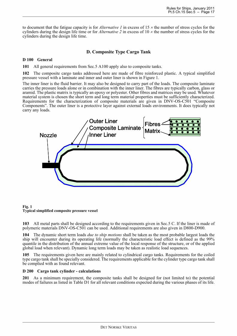
D. Composite Type Cargo TankD 100 General101 All general requirements from Sec.5 A100 apply also to composite tanks.102 The composite cargo tanks addressed here are made of fibre reinforced plastic. A typical simplifiedpressure vessel with a laminate and inner and outer liner is shown in Figure 1. The inner liner is the fluid barrier. It may also be designed to carry part of the loads. The composite laminatecarries the pressure loads alone or in combination with the inner liner. The fibres are typically carbon, glass oraramid. The plastic matrix is typically an epoxy or polyester. Other fibres and matrices may be used. Whatevermaterial system is chosen the short term and long term material properties must be sufficiently characterized.Requirements for the characterization of composite materials are given in DNV-OS-C501 “CompositeComponents”. The outer liner is a protective layer against external loads environments. It does typically notcarry any loads.
Fig. 1Typical simplified composite pressure vessel
103 All metal parts shall be designed according to the requirements given in Sec.5 C. If the liner is made ofpolymeric materials DNV-OS-C501 can be used. Additional requirements are also given in D800-D900.104 The dynamic short term loads due to ship motions shall be taken as the most probable largest loads theship will encounter during its operating life (normally the characteristic load effect is defined as the 99%quantile in the distribution of the annual extreme value of the local response of the structure, or of the appliedglobal load when relevant). Dynamic long term loads may be taken as realistic load sequences.105 The requirements given here are mainly related to cylindrical cargo tanks. Requirements for the coiledtype cargo tank shall be specially considered. The requirements applicable for the cylinder type cargo tank shallbe complied with as found relevant.
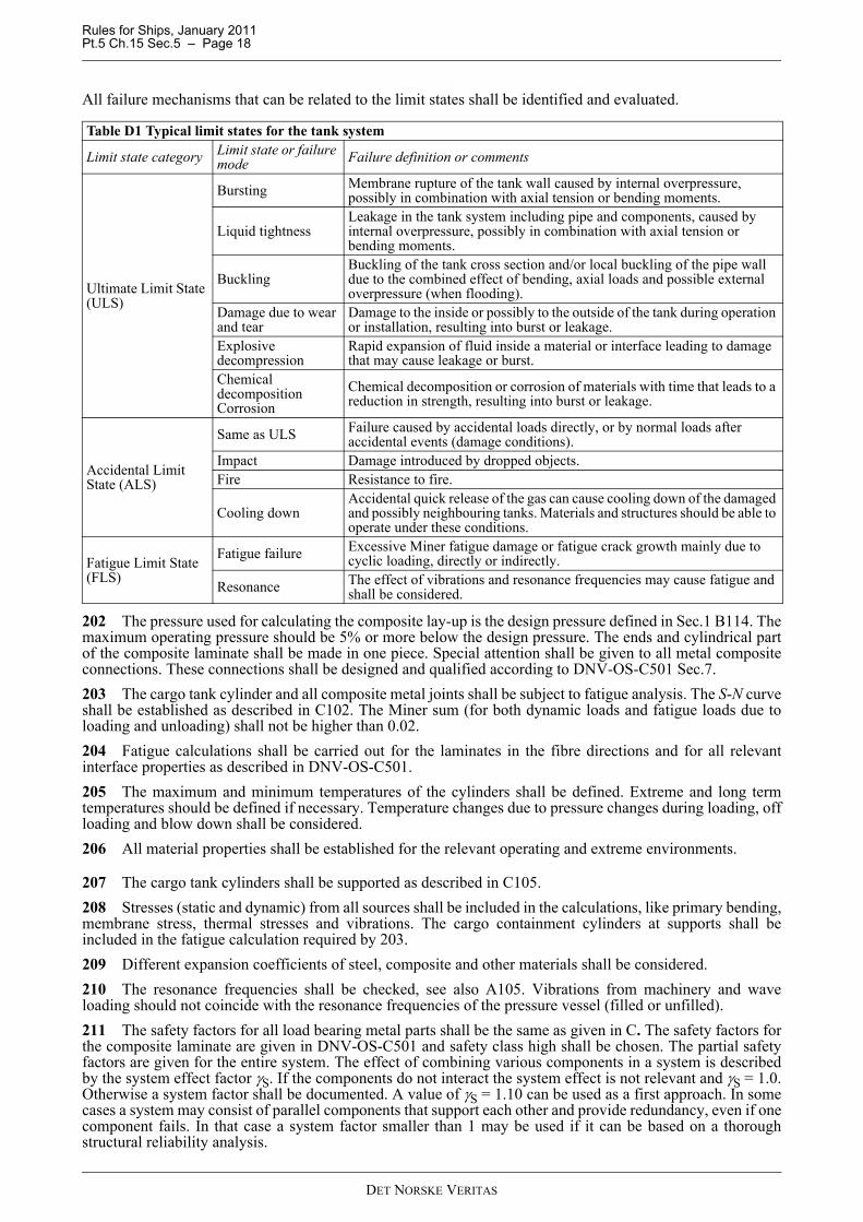
D 200 Cargo tank cylinder - calculations201 As a minimum requirement, the composite tanks shall be designed for (not limited to) the potentialmodes of failures as listed in Table D1 for all relevant conditions expected during the various phases of its life.
FibresMatrix
Outer LinerComposite LaminateInner LinerNozzle
FibresMatrixFibresMatrix
Outer LinerComposite LaminateInner Liner
Outer LinerComposite LaminateInner LinerNozzle
DET NORSKE VERITAS
Rules for Ships, January 2011 Pt.5 Ch.15 Sec.5 – Page 18
All failure mechanisms that can be related to the limit states shall be identified and evaluated.
202 The pressure used for calculating the composite lay-up is the design pressure defined in Sec.1 B114. Themaximum operating pressure should be 5% or more below the design pressure. The ends and cylindrical partof the composite laminate shall be made in one piece. Special attention shall be given to all metal compositeconnections. These connections shall be designed and qualified according to DNV-OS-C501 Sec.7.203 The cargo tank cylinder and all composite metal joints shall be subject to fatigue analysis. The S-N curveshall be established as described in C102. The Miner sum (for both dynamic loads and fatigue loads due toloading and unloading) shall not be higher than 0.02.204 Fatigue calculations shall be carried out for the laminates in the fibre directions and for all relevantinterface properties as described in DNV-OS-C501.205 The maximum and minimum temperatures of the cylinders shall be defined. Extreme and long termtemperatures should be defined if necessary. Temperature changes due to pressure changes during loading, offloading and blow down shall be considered.206 All material properties shall be established for the relevant operating and extreme environments.
207 The cargo tank cylinders shall be supported as described in C105.208 Stresses (static and dynamic) from all sources shall be included in the calculations, like primary bending,membrane stress, thermal stresses and vibrations. The cargo containment cylinders at supports shall beincluded in the fatigue calculation required by 203.209 Different expansion coefficients of steel, composite and other materials shall be considered.210 The resonance frequencies shall be checked, see also A105. Vibrations from machinery and waveloading should not coincide with the resonance frequencies of the pressure vessel (filled or unfilled).211 The safety factors for all load bearing metal parts shall be the same as given in C. The safety factors forthe composite laminate are given in DNV-OS-C501 and safety class high shall be chosen. The partial safetyfactors are given for the entire system. The effect of combining various components in a system is describedby the system effect factor γS. If the components do not interact the system effect is not relevant and γS = 1.0.Otherwise a system factor shall be documented. A value of γS = 1.10 can be used as a first approach. In somecases a system may consist of parallel components that support each other and provide redundancy, even if onecomponent fails. In that case a system factor smaller than 1 may be used if it can be based on a thoroughstructural reliability analysis.
Table D1 Typical limit states for the tank system
Limit state category Limit state or failure mode Failure definition or comments
Ultimate Limit State (ULS)
Bursting Membrane rupture of the tank wall caused by internal overpressure, possibly in combination with axial tension or bending moments.
Liquid tightnessLeakage in the tank system including pipe and components, caused by internal overpressure, possibly in combination with axial tension or bending moments.
BucklingBuckling of the tank cross section and/or local buckling of the pipe wall due to the combined effect of bending, axial loads and possible external overpressure (when flooding).
Damage due to wear and tear
Damage to the inside or possibly to the outside of the tank during operation or installation, resulting into burst or leakage.
Explosive decompression
Rapid expansion of fluid inside a material or interface leading to damage that may cause leakage or burst.
Chemical decomposition Corrosion
Chemical decomposition or corrosion of materials with time that leads to a reduction in strength, resulting into burst or leakage.
Accidental Limit State (ALS)
Same as ULS Failure caused by accidental loads directly, or by normal loads after accidental events (damage conditions).
Impact Damage introduced by dropped objects.Fire Resistance to fire.
Cooling downAccidental quick release of the gas can cause cooling down of the damaged and possibly neighbouring tanks. Materials and structures should be able to operate under these conditions.
Fatigue Limit State (FLS)
Fatigue failure Excessive Miner fatigue damage or fatigue crack growth mainly due to cyclic loading, directly or indirectly.
Resonance The effect of vibrations and resonance frequencies may cause fatigue and shall be considered.
DET NORSKE VERITAS
Rules for Ships, January 2011 Pt.5 Ch.15 Sec.5 – Page 19
Guidance note:In the case of a number of tanks connected in sequence, the failure of one section (i.e. plain pipe or end connector) isequivalent to the failure of the entire system. This is a chain effect in which any component of the sequence cancontribute. As a consequence, the target safety of individual section should be higher than the target safety of the entiresystem, in order to achieve the overall target safety.
---e-n-d---of---G-u-i-d-a-n-c-e---n-o-t-e---
Guidance note:A continuous spoolable tank has only two end connectors (one at each end). Failure of an end connector is also asystem failure. However, since there are only two connectors it is not a chain effect and γS = 1.0 can be used.
---e-n-d---of---G-u-i-d-a-n-c-e---n-o-t-e---
D 300 Cargo tank piping301 It is assumed here that piping is made of metal and the same requirements as given in C200 apply.302 Composite piping may be considered on an individual basis.
D 400 Production requirements and testing after installation401 Fabrication tolerances and hydraulic testing of the complete cargo tank shall be in accordance with DNV-OS-F101 Ch.5 or DNV-OS-C501 Sec.11 as applicable.
Guidance note:A test pressure equal to 1.25 times the design pressure is considered appropriate.
---e-n-d---of---G-u-i-d-a-n-c-e---n-o-t-e---
402 The cargo tanks shall be tested on the ship after installation as a final acceptance test. The test pressureshall be 1.25 times the design pressure.
D 500 Full scale prototype pressure testing and tolerances501 A set of full scale (with respect to diameter, thickness, number of circumferential welds, including end-caps but not necessarily full length) fatigue and burst tests shall be performed and it must be documented thatthe cylinder wall, end-caps and welding have sufficient reliability against fatigue and that the cylinderpossesses sufficient burst resistance. Possible damage during installation or operation shall be included in thedesign tests, see also 504. The sequence of the failure modes in the test shall be the same as predicted in thedesign. If the sequence is different or if other failure modes are observed, the design shall be carefully re-evaluated. Minimum test requirements are given in Table D2.502 Additional testing should be done whenever uncertainties in the analysis cannot be resolved. Theseuncertainties may be related to the structural analysis, boundary conditions, modelling of local geometry,material properties, failure modes, properties of interfaces, etc. The procedure given in DNV-OS-C501 shouldbe followed for testing. 503 Testing may be done at room temperature and with water as a pressure medium if the effect oftemperature changes and fluid changes can be well described. If the effect of changing the environmentalconditions is uncertain, testing should be carried out in the worst conditions and possibly with gas.
Guidance note:Testing with gas requires special safety precautions during testing and it may not be possible to carry out the tests onboard the vessel.
---e-n-d---of---G-u-i-d-a-n-c-e---n-o-t-e---
504 The tank shall be exposed to typical impact damage, like damage from a dropped hammer etc.Subsequently a pressure test and a fatigue test shall be carried out. The testing may be combined with the testsspecified in Table D2.505 The specimen geometry for testing may be chosen to be different from the actual under certainconditions. Specimens may be shorter than in reality. If shorter specimens are chosen, the free length of thetank pipe between end-fittings should be at least 6 x diameter. Scaled specimens may be used if analyticalcalculations can demonstrate that:
— all critical stress states and local stress concentrations in the joint of the scaled specimen and the actual tankare similar, i.e., all stresses are scaled by the same factor between actual tank and test specimen
— the behaviour and failure of the specimen and the actual tank can be calculated based on independentlyobtained material parameters. This means no parameters in the analysis should be based on adjustments tomake large scale data fit
— the sequence of predicted failure modes is the same for the scaled specimen and the actual tank over theentire lifetime of the tank
DET NORSKE VERITAS
Rules for Ships, January 2011 Pt.5 Ch.15 Sec.5 – Page 20
— an analysis method that predicts the test results properly but not entirely based on independently obtainedmaterials data, may be used for other joint geometry. In that case it should be demonstrated that the materialvalues that were not obtained by independent measurements can also be applied for the new conditions.
Tests on previous tanks may be used as testing evidence if the scaling requirement given above are fulfilled.Materials and production process should also be identical or similar. Similarity should be evaluated based onthe requirements in DNV-OS-C501 Sec.4.
506 Burst pressure test: A burst test shall be done and the burst pressure shall be at least the predicted μ -σ, where μ is the mean prediction and σ is standard deviation of the predicted burst pressure. If more than onetest is done the requirements are given in DNV-OS-C501 Sec.10 C200.507 Pressure fatigue testing: Fatigue tests shall be carried out with a typical pressure load sequence. Axialtension or bending should be added if relevant. The most relevant test should be found by evaluating the designanalysis. At least two survival tests shall be carried out. The specimen shall not fail during the survival test andit shall not show unexpected damage. The requirements to the testing are:
— Tests shall be carried out up to five times the maximum number of design cycles with realistic amplitudesand mean loads that the component will experience.
— If realistic pressure sequences cannot be tested or if the anticipated lifetime exceeds 105 cycles, the testprocedure may be changed as given in DNV-OS-C501 Sec.10 C300.
— All tests shall be completed with a pressure test. The failure load or pressure shall be at least the predictedμ - σ, where μ is the mean prediction and σ is one standard deviation of the predicted load.
508 In some cases high amplitude fatigue testing may introduce unrealistic failure modes in the structure. Inother cases, the required number of test cycles may lead to unreasonable long test times. In these cases anindividual evaluation of the test conditions should be made that fulfils the requirements of 507 as closely aspossible.509 Stress rupture testing: Only if the performance of the metal composite interface depends on matrixproperties or adhesives, or if the fibres in the laminate can creep, long term static testing should be performed.Two survival tests should be carried out. Stress rupture tests should be carried out with a typical load sequence or with a constant load. If a clearlydefined load sequence exists, load sequence testing should be preferred. The specimen should not fail duringthe survival test and it should not show unexpected damage. The requirements to the test results are:
— Tests should be carried out up to five times the maximum design life with realistic mean pressure loads thatthe component will experience. If constant load testing is carried out tests should be carried out up to 50times the design life to compensate for uncertainty in sequence effects.
— If the anticipated lifetime exceeds 1 000 hours testing up to 1 000 hours may be sufficient. The load levelsshould be chosen such that testing is completed after 103 hours. The logarithms of the two test results shallfall within μ - σ of the logarithm of the anticipated lifetime, where μ is the mean of the logarithm of thepredicted lifetime and σ is one standard deviation of the logarithm of the predicted lifetime, both interpretedfrom a log(stress)-log(lifetime) diagram for the anticipated lifetime. If more tests are made the requirementsare given in DNV-OS-C501 Sec.10 C300.
— All tests should be completed with a pressure test. The failure load or pressure should be at least thepredicted μ - σ, where μ is the mean prediction and σ is one standard deviation of the predicted load.
510 Liner bond testing: If the design relies on a bond between liner and composite laminate, the quality of
Table D2 Summary of test requirementsName of test Description ReferenceDesign phasePressure test 1 test to failure 506
Pressure fatigue of tank2 tests to 5 × actual number of cycles or survival test to about 100 000 cycles, followed by burst test.
507 - 508
Stress rupture test of tank if matrix properties are critical or fibres can creep
2 tests to 50 x actual lifetime or survival test to about 1 000 hours 509
If the inner liner is bonded to the laminate Test bond between liner and laminate 510If impact requirement Impact tests 511Process Prototype Testing System test 512After fabrication
Pressure test Test to 1.3 times design pressure for each tank component 401
System acceptance test Test to 1.3 times design pressure for each tank component 402
DET NORSKE VERITAS
Rules for Ships, January 2011 Pt.5 Ch.15 Sec.5 – Page 21
the bond shall be tested. Tests can be done on the pipe or representative smaller specimens. If the laminate mayhave cracks, it shall be insured that the cracks do not propagate into the liner or reduce the bond quality betweenliner and laminate. 511 Impact testing: The tank should be exposed to typical impact damage, like damage from a droppedhammer etc. Subsequently a pressure test and a fatigue test should be carried out. The testing may be combinedwith the tests specified above.512 Process prototype testing shall be carried out to document that the system functions as specified withrespect to accumulation and disposal of liquids. It shall be verified that liquid hammer does not occur in the pipingsystem during any operation. Where it is impractical to perform full scale testing, successful operation can besimulated computationally and in small scale testing to provide adequate assurance of functionality.
D 600 Non-destructive testing (NDT)601 Composites laminates shall be inspected according to DNV-OS-C501 Sec.12 B.
D 700 Composite - metal connector interface701 The interface between the metal connector and the composite pipe is a critical part of the tank design.The interface is basically a joint and all general requirements given in DNV-OS-C501 Section for “Joints”should be considered.702 The composite metal connector interface shall be strong enough to transfer all loads considered for theconnector and the pipe section.703 Internal or external pressure on the tank system may be beneficial or detrimental to the performance ofthe joint. This effect shall be considered in the analysis.704 Creep of any of the materials used in the joint may reduce friction, open up potential paths for leakageor lead to cracks. Effects of creep shall be carefully considered.
Guidance note:It is highly recommended to design the joint in a way that it also functions if the matrix of the composite laminate iscompletely degraded. In that case the joint can perform as long as the fibres are intact and sufficient friction betweenfibres and the fibre metal interface exists. Such a joint does not rely on the usually uncertain long-term properties ofthe matrix.
---e-n-d---of---G-u-i-d-a-n-c-e---n-o-t-e---
705 Metal parts should be designed in a way that they do not yield to ensure no changes in the geometricarrangement of the joint. If any yielding can occur a non-linear analysis shall be done taking all relevant loadhistories and accumulated plastic deformations into account. Local yielding in thin sections or near welds shallbe evaluated.706 Possible effects of corrosion on metals and interfaces shall be evaluated.707 Possible galvanic corrosion between different materials shall be considered. An insulating layer betweenthe different materials can often provide good protection against galvanic corrosion.708 Leak tightness of the joint shall be carefully evaluated. In particular possible flow along interfaces shouldbe analysed.
D 800 Inner liner801 Most composite tanks have an inner liner as a fluid barrier. The liner may also carry parts of the pressureload. This inner liner is typically made of metal or polymeric materials.802 It shall be shown that the inner liner remains fluid tight throughout the design life, if it is used as a fluidbarrier.803 The inner liner may contribute to the overall stiffness and strength of the tank system depending on itsstiffness and thickness.804 If the inner liner is only a fluid barrier it usually follows the deformations of the main load bearinglaminate. It shall be shown that the inner liner has sufficiently high strains to failure and yield strains to followall movements of the tank system.805 If the inner liner is designed to carry also part of the pressure loads all requirements from 804 shall befulfilled. In addition, the load bearing capability of the liner shall be checked according to C. The inner linerneeds to deform somewhat and press against the composite laminate before the laminate can support the linerand reduce the loads in the liner. This effect shall be considered. Its magnitude depends on how tightly thelaminate is wound around the liner and on how stiff the laminate is in relation to the liner.806 The inner liner should be operated in its elastic range. Neither operational conditions nor test conditions
DET NORSKE VERITAS

Rules for Ships, January 2011 Pt.5 Ch.15 Sec.5 – Page 22
should bring it to yield. An exception is the first pressure loading called autofretage. Autofretage is commonpractice to pressurize a vessel initially at the factory to such high pressures that the inner liner yields. Thiscreates a tight fit between the liner and laminate. The liner will subsequently be compressed by the outerlaminate when the high pressure is removed.807 Autofretage of the inner liner is common practice. The tank is pressurized initially at the factory to sucha high pressure that the inner liner yields. After removing the pressure the inner liner will be compressed bythe outer laminate. This procedure ensures a tight fit between inner liner and laminate. It shall be shown thatthe inner liner does not buckle due to the compressive loads. The yielding of the inner liner during autofretagealso causes the liner’s welds to yield. This may reduce stress concentrations, but it can also cause local thinningaround the weld. Any thickness variations in the inner liner may cause localised yielding. The weld zone mayhave lower yield strength than the main part of the inner liner. Due to this the inner liner may yield locally closeto the welds. The strain in the localised yield region can be very high, possibly leading to instant rupture, lowerfatigue performance, enhanced creep. The inner liner and its welds shall be analysed taking all these effectsinto account.
Guidance note:A small thin area in the inner liner can be worse than a larger thin area, because the inner liner may only deform byyielding in the thin section. In that case the small thin section will have much higher strains than the large section, ifthe total deformation is the same.
---e-n-d---of---G-u-i-d-a-n-c-e---n-o-t-e---
808 If the inner liner material can creep, then creep will happen especially in the thin highly strained regions.The effect of creep with respect to fatigue, stress rupture and buckling shall be evaluated.809 If the inner liner is under compression, local yielding may create deformations resulting in local or globalbuckling.810 Buckling of the liner due to hoop compression shall be considered as a potential failure mechanism. Thefollowing two phenomena should be considered as a minimum:
— Rapid decompression causes a pressure to build up suddenly between the liner and the composite tank tube,at the same time as the pressure inside the liner suddenly drops. This effect can happen if gas or liquid candiffuse through the inner liner and accumulate in the interface between liner and laminate or inside thelaminate. This effect can be ignored for metal liners, since they are diffusion tight, provided no otherdiffusion path through seals etc. exists in the system.
— As a result of the sustained internal pressure, the liner yields plastically (or undergoes creep deformation)in tension in the hoop direction. Decompression causes the composite tank cylinder to contract,compressing the liner and causing it to buckle. This effect can be prevented by using initially theautofretage process (807) and by keeping the liner below yield during operation.
811 Inner liner specifications with respect to acceptable thickness variations, weld quality, and maximummisalignments should be consistent with the worst cases evaluated in the analysis.812 Polymeric inner liners, like thermoplastic inner liners may be evaluated against the yield criterion inDNV-OS-C501 Sec.6 F.813 The liner may be bonded to the composite laminate or it may be un-bonded.814 A different layer of material may also be placed between the laminate and the liner.815 All possible failure modes of the interface and their consequence to the performance of the system shallbe evaluated.816 If a bond is required between laminate and liner, for example to obtain good buckling resistance of theliner, the performance of the bond shall be tested D510.817 If interfaces only touch each other friction and wear should be considered (DNV-OS-C501 Sec.6 M).818 If the liner is not totally fluid tight, fluids may accumulate between interfaces. They may accumulate invoids or de-bonded areas and or break the bond of the interface. They may also accumulate in the laminate. Theeffect of such fluids should be analysed. The fluid should diffuse more rapidly through the laminate than through the inner liner, and more rapidlythrough the outer liner then through the laminate. Possible effects of rapid decompression of gases should beconsidered. The effect of the slight gas leaks due to diffusion shall be considered in the system analysis.819 If the laminate may have matrix cracks, but the liner shall not crack (or vice versa), it shall be shown thatcracks cannot propagate from one substrate across the interface into the other substrate. Possible de-bondingof the interface due to the high stresses at the crack tip should also be considered.820 It is recommended to demonstrate by experiments that cracks cannot propagate across the interface from
DET NORSKE VERITAS

Rules for Ships, January 2011 Pt.5 Ch.15 Sec.5 – Page 23
one substrate to the other. It should be shown that by stretching or bending both substrates and their interfacethat no cracks form in the one substrate even if the other substrate has the maximum expected crack density.
Guidance note:A weak bond between the substrates is beneficial to prevent crack growth across the interface. However, it means thatdebonding may happen easily.
---e-n-d---of---G-u-i-d-a-n-c-e---n-o-t-e---
821 The inner liner should be strong enough to withstand possible shear, scraping and torsional loads fromequipment running inside tank.822 The inner liner shall be resistant to the internal environment. Possible accumulation of water or otherliquids on the bottom of the tank shall be considered. A possible combination of water and H2S from the gasshall also be considered.
D 900 Outer liner901 An outer liner is usually applied for keeping out external fluids, for protection from rough handling andthe outer environment and for impact protection.902 If no outer liner is applied the outer layers of the laminate have to take the functions of the outer liner.903 The outer liner material shall be chosen so that it is resistant to the external environment, e.g., seawater,temperature, UV etc.904 If the outer liner is exposed to UV radiation in service or during storage, it should be UV resistant.905 Outer liners are not exposed to autofretage. They should be kept below yielding.906 Resistance of the outer liner to handling and the external environment shall be considered. The outer linermay get some damage from handling, but the structural layer underneath should not be affected.907 The performance requirements to the outer liner should not be affected by a possible impact scenario.908 If fluids can diffuse through the inner liner into the load bearing laminate the outer liner may suffer fromblow out if the external pressure is lower than the pressure inside the laminate. Blow out can be prevented bya venting mechanism.909 Blow out will also not happen if it can be shown that the fluids will diffuse from the laminate throughthe outer liner into the external environment more rapidly than from the inside of the tube through the innerliner into the laminate. In addition, the remaining fluid concentration should be low enough that even underlow external pressure the outer liner cannot blow out.
D 1000 Installation1001 A procedure for handling of the composite cargo tanks shall be submitted for information. Theprocedure shall describe how the tanks will be handled to avoid external impacts and point loads.1002 The installation procedure shall as a minimum address the following issues:
— How can impact loads be avoided?— How can impact loads be detected, if they should happen?— What are the loads during installation and handling, point loads should be avoided?— What shall be done in case of fire during installation?— What is the effect of weld spatter, sparks, naked flames, how can it be avoided?
Possible excessive moments and forces from the manifold system during installation should be addressed.
DET NORSKE VERITAS

Rules for Ships, January 2011 Pt.5 Ch.15 Sec.6 – Page 24
SECTION 6 PIPING SYSTEMS IN THE CARGO AREA
A. General
A 100 Bilge, ballast fuel oil piping For piping systems in cargo area not forming a part of the cargo piping the requirements given in Pt.4 Ch.1,Pt.4 Ch.6 and Ch.5 Sec.6 apply. Piping systems common to multiple holds shall be arranged so that release ofgas from one hold space shall not leak into other hold spaces.
A 200 Cargo piping, General
201 Structure and supports shall be suitably shielded from leak from flanges and valves and other possibleleak sources if the cool down effect cannot be shown to be negligible.
202 If cargo piping enters enclosed spaces above main deck in process area, these spaces shall be providedwith overpressure protection in case of high pressure leak or explosion.
A 300 Cargo valves
301 All remotely operated valves shall be capable of local manual operation.
302 The cargo tanks shall be connected to the cargo piping in accordance with the following principles:
— Each cargo tank shall be segregated from the cargo piping by a manually operated stop valve and a remotelyoperated valve in series. A combined manually and remotely operated stop valve is acceptable providedmeans are available to check the integrity of the valve.
— The loading/unloading connection point shall be equipped with a manually operated stop valve and aremotely operated valve in series.
— The remotely operated cargo tank valves and load/unload valves required above shall have emergency shut-down (ESD) functions. The valves shall close smoothly so that excessive pressure surges do not occur.
— The ESD valves shall be arranged so that they close automatically in case of high pressure, sudden pressuredrop during loading/unloading operations and in the event of fire. The ESD valves shall be arranged to beoperated manually from cargo control room and other suitable locations.
— The cargo compressors shall shutdown automatically if the ESD system is activated.
A 400 Cargo piping design
401 The cargo piping system shall as a minimum meet the requirements given in Pt.4 Ch.6 and Ch.5 Sec.6or a standard acceptable to DNV with the following additional requirements:
— The design temperature shall be the minimum temperature achieved during all normal and emergencyprocedures e.g. loading/unloading and pressure relieving shall be considered.
— The design pressure is the maximum pressure to which the system may be subjected to in service e.g. theset point of the safety relief valve (See Sec.7 A101).
— The pipes shall be seamless or equivalent.— Only butt welded and flanged connections of the welding neck type are allowed. Flange connections shall
be limited as far as possible. — All butt welds shall be subject to 100% radiographic testing.— Welding procedure tests and production weld test are required for cargo piping as specified in Ch.5 Sec.6
C600.— After assembly the piping system shall be hydrostatic pressure tested to at least 1.5 times design pressure
prior to installation.— After assembly on board the complete cargo piping shall be subjected to a leak test using air, halides or
other suitable medium according to an approved procedure.— The effects of vibrations imposed on the piping system shall be evaluated.— A complete stress analysis for each branch of the piping system shall be conducted according to ANSI/
ASME B31.3.
402 Procedures for cargo transfer including emergency procedures shall be submitted for approval. Theprocedures shall address potential accidents related cargo transfer, and information regarding emergencydisconnection, emergency shutdown, communication with offshore/onshore terminals etc. shall be included.
DET NORSKE VERITAS

Rules for Ships, January 2011 Pt.5 Ch.15 Sec.7 – Page 25
SECTION 7 OVERPRESSURE PROTECTION OF THE CARGO TANK AND
CARGO PIPING SYSTEM
A. GeneralA 100 Cargo piping101 A pressure relief valve for preventing overpressure in the cargo piping shall be provided. The set pointof the safety relief valve shall not be more than the design pressure of the cargo piping, less the tolerance of therelief valve.
A 200 Cargo tanks201 The cargo tanks shall be provided with a blow down system and an automatic pressure relief system. Thesystem shall ensure safe collection and disposal of pressurised gas during normal operation and duringemergency conditions.The gas from the vent may be cold vented or ignited. If there are provisions for cold venting a gas dispersionanalysis shall be conducted in order to evaluate the extent of the gas dangerous area.202 The blow down system shall meet the following principles:
— The blow down system shall provide means for pressure relieving of individual cargo tanks due to leakage.— The blow down system shall be provided with remote control for blowing down individual cargo tanks.— It shall be possible to determine which of the cargo tanks is leaking based on input from e.g. gas detection
system, pressure sensors in cargo tank sections, temperature in hold space, and pressure in hold space. — Cold venting will be acceptable provided it does not impose an unacceptable risk. There shall be two blow
down valves fitted in series with a common control signal. One of the valves may be common for all cargotanks. It shall be possible to check the integrity of the valves.
— The capacity of the blowdown system shall be sufficient to ensure that rupture of cargo tank or cargo tankpiping will not occur in case of heat input from a fire or cool down from a gas leak.Guidance note:The capacity of the system should be based on evaluation of:- system response time- heat input from defined accident scenarios- material properties and material utilisation ratio- other protection measures, e.g. active and passive fire protection- system integrity requirements.Fire water systems are not normally regarded as reliable protection measures for systems exposed to jet fires. Physicalseparation and passive fire protection should be the preferred means of preventing escalation.
---e-n-d---of---G-u-i-d-a-n-c-e---n-o-t-e---
203 The cargo tanks shall be provided with a pressure relief system appropriate to the design of the cargotank. The set point of the safety relief valve shall not be higher than the design pressure of the cargo tanks, lessthe tolerance of the relief valve. 204 If it proves impractical to install the blow down valves required in 202 and the safety relief valve requiredin 203, then alternative measures may be considered. These include high integrity pressure protection systems(HIPPS) where the cargo valve may also serve as blow down valve and a safety relief valve. The acceptabilityof such systems shall be considered on a case by case basis and will be dependent upon demonstration ofadequate reliability and response of the complete system from detector to actuated device(s). The reliabilitytarget shall be an order of magnitude higher than critical failure of a typical relief device.
DET NORSKE VERITAS

Rules for Ships, January 2011 Pt.5 Ch.15 Sec.8 – Page 26
SECTION 8 GAS-FREEING OF CARGO CONTAINMENT SYSTEM AND PIPING
SYSTEM
A. General A 100 General101 Arrangements for gas freeing shall be provided for all parts of the cargo system. A detailed proceduredescribing this routine shall be included in the cargo handling manual and submitted to DNV for review.
DET NORSKE VERITAS
Rules for Ships, January 2011 Pt.5 Ch.15 Sec.9 – Page 27
SECTION 9 MECHANICAL VENTILATION IN CARGO AREA
A. GeneralA 100 General101 The ship shall meet the requirements given in Ch.5 Sec.10.102 Shut down philosophy for gas detection in cargo area, air ventilation intakes for accommodation andmachinery spaces shall be evaluated and submitted for information.
A 200 Ventilation in hold spaces201 In order to provide for aeration of hold space an efficient ventilation system shall be provided. Theventilation system shall discharge to outlets ensuring safe environment for crew during release of inert gas.
DET NORSKE VERITAS

Rules for Ships, January 2011 Pt.5 Ch.15 Sec.10 – Page 28
SECTION 10 FIRE PROTECTION AND EXTINCTION
A. General A 100 General101 The ship shall meet the requirements for gas carriers given in Ch.5 Sec.11 with additional requirementsspecified in this section. For new concepts the fire loads shall be determined as a part of the Quantitative RiskAssessment referred to in Sec.1 A202.
A 200 Structural fire preventive measures201 Exterior boundaries of superstructures and deckhouses, and including any overhanging decks, shall beA-60 fire-protected for the portions facing the cargo area, the fuel oil storage wing tanks area and the processplant area, and for 3 metres away of any such boundary line.202 If a process plant or any other potential release sources with gas under high pressure is located in thevicinity of accommodation, additional means of fire protection shall be considered.
Guidance note:Additional fire protection may be:- H-60 insulation of the boundaries described in 201- Physical protection preventing a jet from a gas leak exposing accommodation.
---e-n-d---of---G-u-i-d-a-n-c-e---n-o-t-e---
203 Hold space covers facing the process area shall be protected from the process area by a transversefirewall of not less than H-0. Hold space covers facing the engine room area and flare mast aft shall beconstructed with a transverse fire class division of not less than A-0.Hold space covers shall have:
— fire integrity to withstand exposure of a standard fire test used for A-class divisions with exposure fromoutside
— surface flammability characteristics according to resolution A.653(16) (towards weather deck)— sufficient strength and tightness to ensure effective inert atmosphere within hold space for one hour.
204 Hold spaces below the weather deck shall be protected from the turret area or process area by A-0 classdivision. For cargo tanks made of materials with fire resistance properties not equivalent to steel, the hold space covershall be insulated to "A-60" class standard. In addition, hold space covers which are facing a process area orequipment with pressurised hydrocarbons shall be insulated to "H-60" class standard.205 Accommodation, service spaces and engine room below the weather deck shall be separated from theprocess area, turret and cargo holds by means of cofferdams. The minimum distance between the bulkheadsshall be 600 mm.206 Any external boundaries of the engine room or service spaces, casings and the vent mast shall be madeof steel.207 Hold space covers or other essential areas or equipment which may be exposed to heat loads from andignited leak from the cargo tanks/piping shall be adequately protected for the time it takes to depressurise thecargo tanks.208 Divisions formed by bulkheads and decks which comply with the following are regarded as Class H firedivision:
— They shall be constructed of steel or other equivalent material.— They shall be suitably stiffened.— They shall be constructed as to be capable of preventing the passage of gas, smoke and flames up to the end
of the two-hour standard test for hydrocarbon fires. The relevant exposure model is implemented in therevised edition of ISO 834 (HC curve).
— They shall be insulated with approved non-combustible materials or equivalent passive fire protection suchthat the average and maximum temperature of the unexposed side will not rise to more than 140°C and180°C respectively above the original temperature, within the time listed below:
class H-120 120 minutesclass H-60 60 minutes
DET NORSKE VERITAS
Rules for Ships, January 2011 Pt.5 Ch.15 Sec.10 – Page 29
class H-0 0 minutes.
A 300 Means of escape301 Means of escape shall be provided from the engine room or service spaces to accommodation by meansof enclosed shelter, preferably without having to be exposed to the weather deck. 302 Escape routes shall be arranged from the process area and other working zones in the cargo area to themuster area in the accommodation.303 The transverse firewalls required in 201 shall provide protection against heat radiation for lifeboats.
A 400 Firefighter’s outfit401 4 sets of firefighter’s outfits shall be placed in 2 separate fire stations, within the accommodation.402 For concepts where the cargo area is dividing the accommodation and engine room or service spaces, 2sets of firefighter’s outfits are required in the engine room or service spaces in addition to the sets required in401.
A 500 Fire main501 The basic requirements for fire pumps, hydrants and hoses, as given in SOLAS Ch. II-2/10.2, apply withthe additional requirements given in 502 to 508.502 The arrangement shall be such that at least 2 jets of water, not emanating from the same hydrant, areavailable, one of which shall be from a single length of hose that can reach any part of the deck and externalsurfaces of the hold space covers. The minimum pressure at the hydrants with 2 hoses engaged shall be 5.0 bar.Hose lengths shall not exceed 33 m.503 The fire main shall be arranged either as:
— a ring main port and starboard or — as a single line along the centre line through the cargo area provided the fire main is shielded from possible
jet fire occurring from within the cargo piping.
504 Two main fire pumps shall be installed, each with 100% capacity. One pump shall be located forward ofthe cargo area and one pump aft of the cargo area and both pumps shall be arranged with remote control fromboth the bridge and the engine room.505 Both main fire pumps shall at any time during operation, when the ship is not gas-free, be available forstart and delivery of water. The fire main shall be pressurised for immediate delivery of water at hydrants forengaging at least two effective jets of water onto the weather deck. The fire pumps shall start automaticallyupon low pressure detection in the fire main.
506 Remote controlled isolation valves shall be arranged on the weather deck at each end of the fire mainleading into the cargo or process area. The isolation valves shall be on the protected side of the fire wall orboundary. Manual operated stop valves shall be provided between each cargo hold space, and the distancebetween the valves shall not exceed 40 m.507 All pipes, valves, nozzles and other fittings in the fire fighting system shall be resistant to corrosion byseawater and to the effect of fire.508 Mooring equipment positioned within gas dangerous zone shall be protected by a water sprinkler systemwith a capacity of not less than 5 l/m2/minute. The sprinkler system shall be activated prior to anysimultaneously use of the mooring equipment and cargo handling. If only one side of the mooring equipmentis used at a time, the capacity for the water supply may be based on one side in operation only. The watersprinkler system may be served from the fire main. 509 The cargo load and unload area on the open deck shall be covered by water monitors which can beremotely controlled from a safe location.
A 600 Dual agent (water and powder) for process and load/unload area601 The system shall be capable of delivering water and powder from at least two widely separatedconnections to the process area, cargo load and unload area and any other high fire risk areas located on theopen deck. The length of the hoses shall be 25 m to 30 m. 602 Water supply may be taken from the main fire pumps and fire main if the added capacity of the systemis included in capacity calculation for the main fire pumps. Powder shall be arranged in two separate units, eachwith the following discharge capacities:
— 3.5 kg/s powder for not less than 60 seconds for one hand held hose.
DET NORSKE VERITAS

Rules for Ships, January 2011 Pt.5 Ch.15 Sec.10 – Page 30
A 700 Water spray701 Water spray is not an acceptable means for complying with the minimum structural fire integrity givenin 200. 702 The following shall be protected by water spray:
— process area— turret— unprotected and pressurised cargo tank/deck piping— Emergency Shut Down (ESD) valves— other important equipment for controlling the pressure in the cargo tanks due to fire— the part of accommodation facing the cargo area— external bulkheads of hold space covers facing the engine room and the flare mast.
703 The system shall be capable of covering all areas mentioned in 702 with a uniformly distributed waterspray of at least 10 l/m2 per minute for horizontal projected surfaces and 4 l/m2 per minute for vertical surfaces.704 The outlets of gas disposal systems, e.g. flare, cold vent or pressure relief valves shall be led to an areawhere radiation, heat or gases will not cause any hazard to the vessel, personnel or equipment. The heatradiation from the flare towards the cargo holds or other important equipment or areas shall be calculated toverify that the heat load does not lead to high temperatures in the cargo holds or equipment failure. The flareshall comply with API RP521 or equivalent. 705 The water spray main shall be arranged either as:
— a ring main port and starboard or — as a single line along the centre line through the cargo area provided the fire main is shielded from possible
jet fire occurring from within the cargo piping.
706 Both water spray pumps shall be available for immediate start up and delivery of water.707 2 water spray pumps shall be installed, each with 100% capacity. One pump shall be located forward ofthe cargo area and one pump aft of the cargo area and both pumps shall be arranged with remote control fromboth the bridge and the engine room.708 Each water spray pump capacity shall be based on simultaneous demand for water spray to all areasrequired in 702, 703 and 704.709 Remote controlled isolation valves shall be arranged on the weather deck at each end of the fire mainleading into the cargo or process area. The isolation valves shall be on the protected side of the fire wall orboundary. Manual operated stop valves shall be provided between each cargo hold space, and the distancebetween the valves shall not exceed 40 m.
A 800 Spark arrestors801 Exhaust outlet from internal combustion machinery and boilers shall be provided with spark arrestors.
DET NORSKE VERITAS

Rules for Ships, January 2011 Pt.5 Ch.15 Sec.11 – Page 31
SECTION 11 ELECTRICAL INSTALLATIONS
A. GeneralA 100 General101 The ship shall meet the requirements given in Ch.5 Sec.12 as applicable.
DET NORSKE VERITAS
Rules for Ships, January 2011 Pt.5 Ch.15 Sec.12 – Page 32
SECTION 12 CONTROL AND MONITORING
A. GeneralA 100 General101 The ship shall meet the applicable requirements given in Ch.5 Sec.13 with the additional requirementsgiven in this section.102 Alarms shall be located on the navigating bridge and in the cargo control room.103 Means for detection of moisture and H2S at the load/unload or shore connection shall be provided.104 As a minimum the following location or spaces shall be monitored for gas:
— suitable positions in each hold space— deck piping (line sensors)— ventilation inlets for gas safe spaces— ventilation outlets for gas dangerous spaces— air inlets to machinery spaces— manifold area.
105 As a minimum the following location or spaces shall be fitted with pressure indicators and alarm:
— each hold space— each cargo tank— cargo piping at load/unload connection.
106 Temperature sensors and oxygen indicators shall be fitted in the hold space.107 Means for temperature measurement of the cargo within the cargo tanks shall be provided.108 The temperature in the cargo tanks shall be monitored at a representative location during pressure relief(e.g. during unloading, blowdown). It shall be controlled that the temperature does not fall below the minimumdesign temperature.
DET NORSKE VERITAS
Rules for Ships, January 2011 Pt.5 Ch.15 Sec.13 – Page 33
SECTION 13 TESTS AFTER INSTALLATION
A. GeneralA 100 General101 All systems shall be tested before the ship is taken into service.
DET NORSKE VERITAS

Rules for Ships, January 2011 Pt.5 Ch.15 Sec.14 – Page 34
SECTION 14 FILLING LIMITS FOR CARGO TANKS
A. GeneralA 100 General101 The pressure in the cargo tanks, after filling, shall be limited so that the pressure does not increase above95% of the design pressure at any time during transport or unloading taking into account:
— for a system without cooling, the ambient temperature conditions given in Ch.5 Sec.7 A104— for a system provided with a cooling system, the capacity of the cooling system and the ambient
temperature conditions given in Ch.5 Sec.7 A104.
DET NORSKE VERITAS
Rules for Ships, January 2011 Pt.5 Ch.15 Sec.15 – Page 35
SECTION 15 GAS SPECIFICATION
A. GeneralA 100 General101 The gas shall have a water dew point that during all operation modes does not lead to formation ofhydrates or corrosion due to free water in the system.102 Sour services shall be handled in compliance with supplementary requirements in DNV-OS-F101.
DET NORSKE VERITAS

Rules for Ships, January 2011 Pt.5 Ch.15 Sec.16 – Page 36
SECTION 16 IN SERVICE INSPECTION
A. GeneralA 100 General101 An inspection and monitoring philosophy shall be established, and this shall form the basis for a detailedinspection and monitoring program. 102 For the cylinder type cargo tank the program shall as a minimum address:
— number of cargo tank cylinders to monitor— inspection tools and accuracy— periodical surveys— NDT requirements— destructive testing of cargo tank cylinders if found necessary— cargo tank piping, fittings and supports— cargo piping, fittings and supports.
The inspection plan shall ensure that cracks and corrosion are detected with high reliability.
DET NORSKE VERITAS