DNV Amendments.pdf
18
DNV OFFSHORE CODES DET NORSKE VERITAS AMENDMENTS AND CORRECTIONS APRIL 2002
-
Upload
esapermana-riyan -
Category
Documents
-
view
42 -
download
0
Transcript of DNV Amendments.pdf

7/21/2019 DNV Amendments.pdf
http://slidepdf.com/reader/full/dnv-amendmentspdf 1/18
DNV OFFSHORE CODES
DET NORSKE VERITAS
AMENDMENTS AND CORRECTIONS
APRIL 2002

7/21/2019 DNV Amendments.pdf
http://slidepdf.com/reader/full/dnv-amendmentspdf 2/18
Comments may be sent by e-mail to
For subscription orders or information about subscription terms, please use
Comprehensive information about DNV services, research and publications can be found at ://www.dnv.com , or can be obtained from DNV, Veritas-veien 1, N-1322 Høvik, Norway; Tel +47 67 57 99 00, Fax +47 67 57 99 11.
© Det Norske Veritas. All rights reserved. No part of this publication may be reproduced or transmitted in any form or by any means, including pho-tocopying and recording, without the prior written consent of Det Norske Veritas.
Computer Typesetting (FM+SGML) by Det Norske Veritas.Printed in Norway by GCS AS.
If any person suffers loss or damage which is proved to have been cau sed by any negligent act or omission of Det Norske Veritas, then Det Norske Veritas shall pay compensation to such personfor his proved direct loss or damage. However, the compensation shall not exceed an amount equal to ten times the fee charged for the service in question, provided that the maximum compen-sation shall never exceed USD 2 million.In this provision "Det Norske Veritas" shall mean the Foundation Det Norske Veritas as well as all its subsidiaries, directors, officers, employees, agents and any other acting on behalf of Det
DET NORSKE VERITAS (DNV) is an autonomous and independent foundation with the objectives of safeguarding life, prop-erty and the environment, at sea and onshore. DNV undertakes classification, certification, and other verification and consultancyservices relating to quality of ships, offshore units and installations, and onshore industries world-wide, and carries out researchin relation to these functions.
DNV Offshore Codes consist of a three level hierarchy of documents:
— Provide principles and procedures of DNV classification, certification, verification and con-
sultancy services.— Provide technical provisions and acceptance criteria for general use by the offshore industry as well asthe technical basis for DNV offshore services.
— Provide proven technology and sound engineering practice as well as guidance for the higher levelOffshore Service Specifications and Offshore Standards.
DNV Offshore Codes are offered within the following areas:A) Qualification, Quality and Safety MethodologyB) Materials TechnologyC) StructuresD) SystemsE) Special FacilitiesF) Pipelines and Risers
G) Asset Operation

7/21/2019 DNV Amendments.pdf
http://slidepdf.com/reader/full/dnv-amendmentspdf 3/18DET NORSKE V ERITAS
DNV Offshore Codes, April 2002 Contents – Page 3
DNV-OSS-101: Rules for Classification of Offshore Drilling andSupport Units, April 2002 ................................................................. 6DNV-OSS-102: Rules for Classification of Floating Production andStorage Units, April 2002 .................................................................. 6DNV-OSS-103: Rules for Classification of LNG/LPG FloatingProduction and Storage Units or Installations, May 2001................. 6DNV-OSS-121: Classification based on Performance CriteriaDetermined from Risk Assessment Methodology, May 2001........... 6DNV-OSS-202: Verification for Compliance with UK ShelfRegulations, March 2001................................................................... 6DNV-OSS-301: Certification and Verification of Pipelines,October 2000...................................................................................... 6DNV-OSS-303: Risk Based Verification, April 2001.......................6
DNV-OS-A101: Safety Principles and Arrangement, January 2001 7DNV-OS-B101: Metallic Materials, January 2001 ........................... 7DNV-OS-C101: Design of Offshore Steel Structures, General (LRFDmethod), October 2000 ...................................................................... 7DNV-OS-C102: Structural Design of Offshore Ships,October 2000...................................................................................... 7DNV-OS-C103: Structural Design of Column Stabilised Units(LRFD method), October 2000.......................................................... 8DNV-OS-C104: Structural Design of Self-elevating Units (LRFDmethod), January 2001....................................................................... 8DNV-OS-C105: Structural Design of TLPs (LRFD method), January 2001 ..................................................................................... 8DNV-OS-C106: Structural Design of Deep Draught Floating Units(LRFD method), January 2001 .......................................................... 8DNV-OS-C201: Structural Design of Offshore Units (WSD method),March 2001 ........................................................................................ 8DNV-OS-C301: Stability and Watertight Integrity, January 2001.... 8DNV-OS-C401: Fabrication and Testing of Offshore Structures,January 2001 ...................................................................................... 8DNV-OS-D101: Marine and Machinery Systems and Equipment,January 2001 ...................................................................................... 8DNV-OS-D201: Electrical Systems and Equipment, March 2001....8DNV-OS-D202: Instrumentation and Telecommunication Systems,October 2000...................................................................................... 9
DNV-OS-D301: Fire Protection, January 2001................................. 9DNV-OS-E101: Drilling Plant, October 2000.................................10DNV-OS-E201: Hydrocarbon Production Plant, October 2000......10
DNV-OS-E301: Position Mooring, June 2001................................10DNV-OS-E401: Helicopter Decks, March 2001 ............................. 10DNV-OS-F101: Submarine Pipeline Systems, 2000....................... 10DNV-OS-F201: Dynamic Risers, 2001 ........................................... 16
DNV-RP-A201: Standard Documentation Types,November 2000 ............................................................................... 17DNV-RP-A202: Documentation of Offshore Projects,January 2001....................................................................................17DNV-RP-A203: Qualification Procedures for New Technology,September 2001 ............................................................................... 17DNV-RP-B401: Cathodic Protection Design, 1993 ........................ 17DNV-RP-C102: Structural Design of Offshore Ships,February 2002..................................................................................17DNV-RP-C103: Column Stabilised Units, October 2001 ............... 17DNV-RP-C202: Buckling Strength of Shells, 2000........................ 17DNV-RP-C203: Fatigue Strength Analysis of Offshore SteelStructures, October 2001 ................................................................. 17DNV-RP-E301: Design and Installation of Fluke Anchors in Clay,2000 ........................................................................................17DNV-RP-E302: Design and Installation of Drag-in Plate Anchors inClay, 2000. ....................................................................................... 17DNV-RP-E305: Onbottom Stability Design of Submarine Pipelines,1988 ........................................................................................17DNV-RP-F101: Corroded Pipelines, 1999 ...................................... 17DNV-RP-F104: Mechanical Pipeline Couplings, 1999................... 18
DNV-RP-F105: Free Spanning Pipelines, March 2002 .................. 18DNV-RP-F106: Factory Applied External Pipeline Coatings forCorrosion Control, 2000 .................................................................. 18DNV-RP-F107: Risk Assessment of Pipeline Protection,March 2001 ...................................................................................... 18DNV-RP-G101: Risk Based Inspection of Offshore Topsides StaticMechanical Equipment, January 2002.............................................18DNV-RP-O401: Safety and Reliability of Subsea Systems,April 1985 ........................................................................................ 18DNV-RP-O501: Erosive Wear in Piping Systems, 1999 ................ 18

7/21/2019 DNV Amendments.pdf
http://slidepdf.com/reader/full/dnv-amendmentspdf 4/18DET NORSKE VERITAS
DNV Offshore Codes, April 2002Page 4 – Contents

7/21/2019 DNV Amendments.pdf
http://slidepdf.com/reader/full/dnv-amendmentspdf 5/18DET NORSKE V ERITAS
DNV Offshore Codes, Amendments and Corrections, April 2002 Sec.1 – Page 5

7/21/2019 DNV Amendments.pdf
http://slidepdf.com/reader/full/dnv-amendmentspdf 6/18DET NORSKE VERITAS
DNV Offshore Codes, Amendments and Corrections, April 2002Page 6 – Sec.2

7/21/2019 DNV Amendments.pdf
http://slidepdf.com/reader/full/dnv-amendmentspdf 7/18DET NORSKE V ERITAS
DNV Offshore Codes, Amendments and Corrections, April 2002 Sec.3 – Page 7
The ESD central control unit shall be powered from amonitored Uninterruptible Power Supply (UPS) capable of atleast 30 minutes continuous operation on loss of its electricalpower supply systems. The UPS shall be powered from boththe main and the emergency power system.
°
According to DNV-OS-C101 material shall be catego-rised into a , or category. With ref-erence to the application of material classes as given in theRules for Classification of Ships Pt.3 Ch.1 or Pt.3 Ch.2 the re-lationship between the material classes and structural catego-ries is as given in Table A1.
For stiffened plates, the plates are considered as cate-gory whilst the stiffeners are considered as catego-ry.
Typical elements for offshore ships, which are not givenin the Rules for Classification of Ships Pt.3 Ch.1 or Pt.3 Ch.2,are given in 300 and 400.
The following locations are considered primary catego-
ry:
— turret structure
— pipe rack stanchions— drillfloor substructure— helicopter deck substructure— flare supporting structure
crane pedestals bow recess area:
— bilge keels (on turret-moored and spread moored units)
Global shear capacity check can in principle be carried out in the same manneras the global moment capacity check since all stress components and lateralpressure are included in the capacity check of each panel. However, in the sec-tions with the highest shear stresses, an acceptable procedure will be to carryout one moment capacity check for each local panel for the design wave result-ing in maximum bending moment combined the associates shear stress, andone shear capacity check according to equation in 402 based on maximum sec-tion shear force and associated bending moment.
≥
Secondary
AB/BWD/DWE/EW
AH/AHWDH/DHWEH/EHW
FHAEH
DEH/DEHWEEH/EEHW
FEH
3060
15015050
10015015060
150150150
3060
15015050
10015015060
150150150
2550
1001504080
15015050
100150150
204080
1503060
1501504080
150150
Primary
AB/BWD/DWE/EW
AH/AHWDH/DHWEH/EHWFH
AEHDEH/DEHWEEH/EEHW
FEH
304060
1502550
1001503060
150150
203060
1502550
1001503060
150150
102550
1002040801502550
100150
N.A.204080153060150204080
150
Special
D/DWE/EW
AH/AHWDH/DHWEH/EHW
FHAEH
DEH/DEHWEEH/EEHW
FEH
3560102550
100153060
150
3060102550
100153060
150
2550
N.A.204080102550
100
2040
N.A.153060
N.A.204080
N.A. = no application
I, II Secondary
III PrimaryIV, V Special
7/21/2019 DNV Amendments.pdf
http://slidepdf.com/reader/full/dnv-amendmentspdf 8/18DET NORSKE VERITAS
DNV Offshore Codes, Amendments and Corrections, April 2002Page 8 – Sec.3
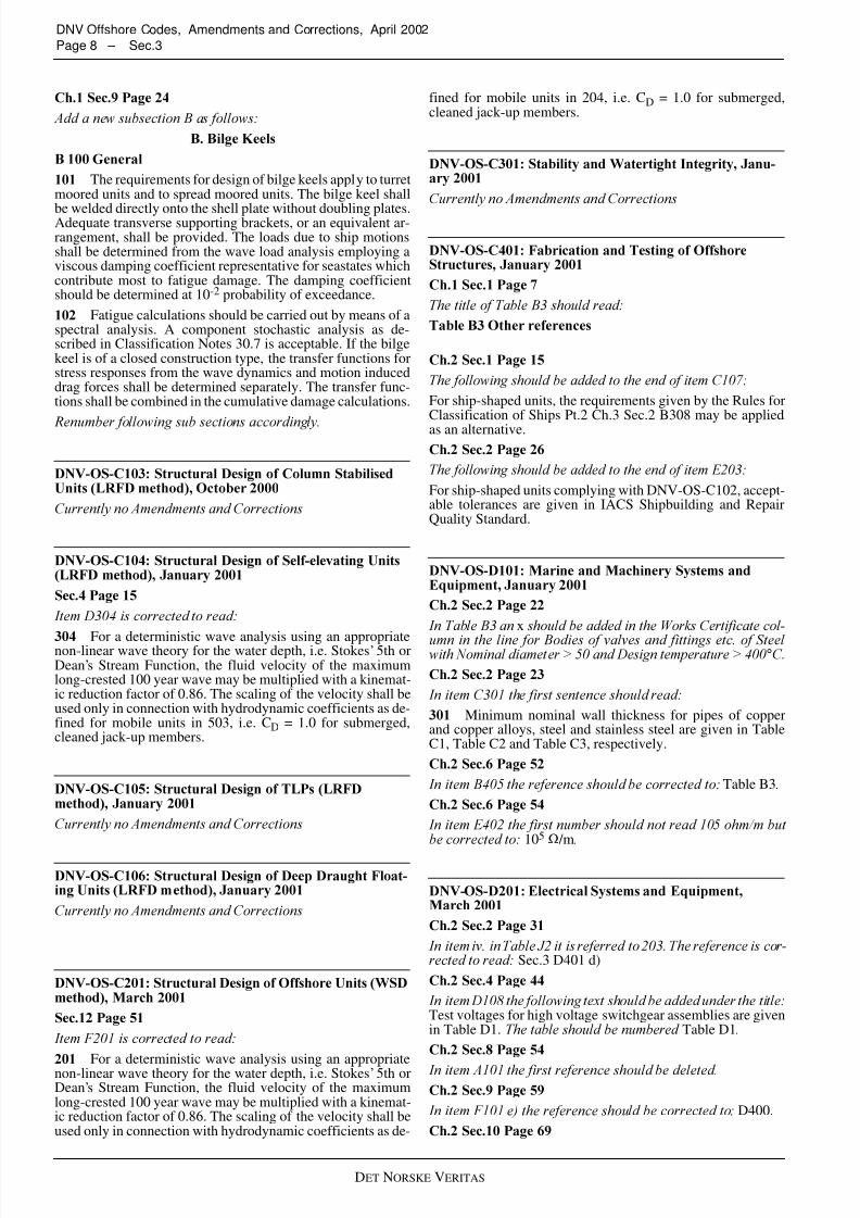
The requirements for design of bilge keels apply to turretmoored units and to spread moored units. The bilge keel shall
be welded directly onto the shell plate without doubling plates.Adequate transverse supporting brackets, or an equivalent ar-rangement, shall be provided. The loads due to ship motionsshall be determined from the wave load analysis employing aviscous damping coefficient representative for seastates whichcontribute most to fatigue damage. The damping coefficientshould be determined at 10 -2 probability of exceedance.
Fatigue calculations should be carried out by means of aspectral analysis. A component stochastic analysis as de-scribed in Classification Notes 30.7 is acceptable. If the bilgekeel is of a closed construction type, the transfer functions forstress responses from the wave dynamics and motion induceddrag forces shall be determined separately. The transfer func-tions shall be combined in the cumulative damage calculations.
For a deterministic wave analysis using an appropriatenon-linear wave theory for the water depth, i.e. Stokes ’ 5th orDean ’s Stream Function, the fluid velocity of the maximumlong-crested 100 year wave may be multiplied with a kinemat-ic reduction factor of 0.86. The scaling of the velocity shall beused only in connection with hydrodynamic coefficients as de-fined for mobile units in 503, i.e. C D = 1.0 for submerged,cleaned jack-up members.
For a deterministic wave analysis using an appropriatenon-linear wave theory for the water depth, i.e. Stokes ’ 5th orDean ’s Stream Function, the fluid velocity of the maximumlong-crested 100 year wave may be multiplied with a kinemat-ic reduction factor of 0.86. The scaling of the velocity shall beused only in connection with hydrodynamic coefficients as de-
fined for mobile units in 204, i.e. C D = 1.0 for submerged,cleaned jack-up members.
For ship-shaped units, the requirements given by the Rules forClassification of Ships Pt.2 Ch.3 Sec.2 B308 may be appliedas an alternative.
For ship-shaped units complying with DNV-OS-C102, accept-able tolerances are given in IACS Shipbuilding and RepairQuality Standard.
x
°
Minimum nominal wall thickness for pipes of copper
and copper alloys, steel and stainless steel are given in TableC1, Table C2 and Table C3, respectively.
Table B3
105 Ω /m
Sec.3 D401 d)
Test voltages for high voltage switchgear assemblies are givenin Table D1. Table D1
D400.

7/21/2019 DNV Amendments.pdf
http://slidepdf.com/reader/full/dnv-amendmentspdf 9/18DET NORSKE V ERITAS
DNV Offshore Codes, Amendments and Corrections, April 2002 Sec.3 – Page 9
— reverse power protection.
The voltage and speed regulation under normal and transientconditions shall be within the limits given in Sec.2 A, Sec.2 E,Sec.5 B and the Rules for Classification of Ships Pt.4 Ch.3.
User inputdevice.
One command location is to be designated as the main
command location. The main command location is to be inde-pendent of other command locations.
200 k Ω
C100
Ch.2 Sec.1F500
As well as representing DNV's interpretation of safe en-gineering practice for general use by the offshore industry, theoffshore standards also provide the technical basis for DNVclassification, certification and verification services.
A complete description of principles, procedures, appli-cable class notations and technical basis for offshore classifi-cation is given by the DNV Offshore Service Specifications(OSS).
Classification procedures and requirements specificallyapplicable in relation to the technical requirements given inCh.2 of this standard are given in this chapter.
Any deviations, exceptions and modifications to the de-sign codes and standards given as recognised reference codesshall be approved by DNV.
Where codes and standards call for the extent of criticalinspections and tests to be agreed between contractor or man-ufacturer and client, the resulting extent is to be agreed withDNV.
DNV may accept alternative solutions found to repre-sent an overall safety level equivalent to that stated in the re-quirements of this standard.
Equipment shall be certified consistent with its functionsand importance for safety.
Equipment referred to in this standard will be catego-rised as follows:
— equipment related to safety for which a DNV certificate isrequired.
Category I equipment is subdivided into IA and IB categorisa-tion.
— equipment related to safety for which a works certificateprepared by the manufacturer is accepted.
For equipment category I, the following approval proce-dure shall be followed:
— design approval, followed by a design verification report(DVR) or type approval certificate
— fabrication survey followed by issuance of a product cer-tificate.
Depending on the required extent of survey, category Iequipment is subdivided into IA and IB with the specified re-quirements as given below:
— pre-production meeting, as applicable, prior to the start of fabrication
— class survey during fabrication— witness final functional, pressure and load tests, as appli-
cable— review fabrication record.
— pre-production meeting (optional)— witness final functional, pressure and load tests, as appli-
cable— review fabrication record.
The extent of required survey by DNV is to be decided on thebasis of manufacturer's QA/QC system, manufacturing surveyarrangement (MSA) with DNV and type of fabrication meth-ods.
It should be noted that the scopes defined for category IA and IBare typical and adjustments may be required based on considera-tions such as:- complexity and size of a delivery- previous experience with equipment type- maturity and effectiveness of manufacturer ’s quality assur-
ance system

7/21/2019 DNV Amendments.pdf
http://slidepdf.com/reader/full/dnv-amendmentspdf 10/18DET NORSKE VERITAS
DNV Offshore Codes, Amendments and Corrections, April 2002Page 10 – Sec.3
- degree of subcontracting.
---e-n-d---of---G-u-i-d-a-n-c-e---n-o-t-e---
Equipment of category II is normally accepted on the ba-sis of a works certificate prepared by the manufacturer. Thecertificate shall contain the following data as a minimum:
— equipment specification or data sheet— limitations with respect to operation of equipment— statement (affidavit) from the manufacturer to confirm
that the equipment has been constructed, manufacturedand tested according to the recognised methods, codes andstandards.
Independent test certificate or report for the equipment or ap-proval certificate for manufacturing system may also be accept-ed.
---e-n-d---of---G-u-i-d-a-n-c-e---n-o-t-e---
Categorisation of safety critical equipment is given in
Table B1. Equipment that is considered important for safety,which is not listed, shall be categorised after special consider-ation.
B103, C202, C402 and C601.
Ch.2Sec.1 C400
Ch.2 Sec.5F
Sec.2 B400
Sec.2 A202
Sec.2 G300
Ch.2 Sec.5 D
Ch.2 Sec.4P
DNV-OS-F101 Submarine Pipeline Systems, 2000
British SteelNirasRøntgen Technische Dienst bvSeaflexShaw Pipeline Services Ltd.Vallourec & Mannesmann
yield stress
The maximum pressure that can beattained at the wellhead during closure of valves closest to thewellhead (wellhead isolation). This implies that pressure tran-sients due to valve closing shall be included.
is determined by:
LSZ = |L1| - |L2| - |L3|L1 = lowest astronomic tide level (LAT)
L2 = 30% of the splash zone wave-related height definedin 303L3 = upward motion of the riser, if applicable
is determined by:
USZ = |U1| - |U2| - |U3|U1 = highest astronomic tide level (HAT)U2 = 70% of the splash zone wave-related height defined
in 303U3 = settlement or downward motion of the riser, if appli-
cable.
BM Base materialL Load effectPWHT Post weld heat treatmentRT Radiographic testingST Surface testingToFD Time of flight detectionUT Ultrasonic testing
Fire dampers XFire water pumps XPressurised components in fire extinguishing sys-tem
X
Fire hose X
Hose reels and associated equipment XNozzles XEquipment for fixed fire fighting installations XFire resisting divisions and materials XDoors XWindows XFire and gas detectors XWheeled and portable extinguishing system X

7/21/2019 DNV Amendments.pdf
http://slidepdf.com/reader/full/dnv-amendmentspdf 11/18DET NORSKE V ERITAS
DNV Offshore Codes, Amendments and Corrections, April 2002 Sec.3 – Page 11
For the system pressure test condition, the local test pressure isconsidered as incidental pressure. In order to calculate the corre-sponding p ld, included in ∆pd above, the local test pressure shallbe calculated as:
where h ref is the vertical distance between the point in questionand the reference height and γ inc should be 1.1. The same ap-proach applies to when the shut-in pressure is used.
---e-n-d---of---G-u-i-d-a-n-c-e---n-o-t-e---
The load effect factors apply to all design formats unless ex-
plicitly stated.
pb(t2) = Burst pressure Eq. (5.15)αc = Flow stress parameter accounting for strain harden-
ing given by:
but maximum 1.20
The maximum yield to ultimate stress ration, αh, is found in Ta-ble 6-3 and Table 6-6. The increase of this factor with 0.02 in ac-cordance with footnote 5 and 3 in these tables respectively doesnot apply since it is already included in the factor 0.78.
---e-n-d---of---G-u-i-d-a-n-c-e---n-o-t-e---
Propagation buckling cannot be initiated unless local
buckling has occurred. In case the external pressure exceedsthe criteria given below, buckle arrestors should be installedand spacing determined based on consequences of failure. Thepropagating buckle criterion reads:
Linepipe formed from strip (skelp) and welded with onelongitudinal seam, without the use of filler metal. The longitu-dinal seam is generated by high frequency current (minimum100 kHz) applied by induction or conduction. The weld area(heat affected area) or the entire pipe shall be heat treated. Theforming may be followed by cold expansion to obtain the re-quired dimensions.
If materials shall be used at a design temperature above50°C, the yield strength at the T max may be determined duringthe qualification of the manufacturing procedure specification.This information shall be obtained either by use of the curvesin Sec.5 B600 or by testing.
The hardness of base material, cladding material, HAZ,weld metal and the metallurgical bonding area shall meet therelevant requirements of this standard (see Table 6-3 and 6-6).
Plates and strip shall be subject to 100% visual examina-tion on both sides. The inspection shall be performed in a suf-ficiently illuminated area (approximately 500 lx) by trainedpersonnel with sufficient visual acuity (e.g. Jaegar J-w eye-sight test at 300 mm within the last 12 months). The surfacefinish produced by the manufacturing process, shall ensure thatsurface imperfections can be detected by visual inspection.
HFW, EBW and LBW pipes, only.
m mm
Repair welding of the weld seam is allowed for SAWLand SAWH pipes only and shall be performed in accordancewith qualified welding repair procedures. Requirements forwelding repair procedures are given in Appendix C. Repairwelding may only be performed subject to the following limi-tations:
∆pd γ pp t
γ in c--------- ρtgh ref pe–+ =
αc 1 β–( ) βf uf y----+=
β0.4 q h for D/t 2 15<+
0( .4 q h ) 60 D/t 2–( ) /45 for 15 D/t 2≤ 60≤+
0 for D/t 2 60>=
qh
p ld pe–( )pb t2( )----------------------- 2
3------- for p ld pe>
0 for p ld pe≤=
ppr 35f yαfab
t2D---- 2.5
=
10 -2 - 10 -3 To be evaluated on a case by case basis
Metallographicexamination
Pipe bodyWeldment
Q(&P 9)Q
Q&PQ&P
Q&PQ&P
pe
ppr
γ mγ sc-------------≤

7/21/2019 DNV Amendments.pdf
http://slidepdf.com/reader/full/dnv-amendmentspdf 12/18DET NORSKE VERITAS
DNV Offshore Codes, Amendments and Corrections, April 2002Page 12 – Sec.3
The out-of-roundness for pipe ends shall be calculatedby the following formula:
The chemical composition, taken from the product anal-ysis, of material for hot-formed components, castings andforgings, shall not exceed the values given in Table 7-4. Thenotes given in Table 7-5 shall apply, except Note 9 and Note10.
For material to be quenched and tempered, the contentof hardening elements Cr, Mo, Cu and Ni shall be sufficient toobtain the desired microstructure in the centre of the compo-nent. The selected chemical composition shall have adequatehardenability to ensure through thickness hardening of the re-spective component.
Mother pipe in C-Mn steels shall be delivered in the nor-
malised, quenched and tempered or TMCP condition.
In general all the requirements given in Sec.6 D100 shallapply. The chemical composition of pipe for bends shall com-ply with Table 6-7 and Table 6-8 as relevant.
In situations where dedicated mother pipes are not avail-able for manufacturing of bends, the factors given in G100 andG200, especially G108, should be considered in order to selectthe most appropriate pipe for bend manufacturing.
— Base material in the arc outer radius longitudinal andtransverse (total 2 specimens)
— Base material in the start transition area outer radius lon-gitudinal and transverse (total 2 specimens) unless 903 isapplicable.
— Base material in the arc outer radius longitudinal andtransverse (total 2 sets)— Base material in the start transition area outer radius lon-
gitudinal and transverse (total 2 sets) unless 903 is appli-cable.
— Cross weld tensile testing in the arc area (one specimen)— Cross weld tensile testing in the start transition area (one
specimen) unless 903 is applicable
— Weld metal, FL, FL + 2 mm and FL + 5 mm in the arc (4sets)
— Weld metal in the start transition area (1 set) unless 903 isapplicable.
The concrete coating shall be reinforced by steel barswelded to cages or by wire mesh steel. The following recom-mendations apply: For welded cages, the spacing between cir-cumferential bars should be maximum 120 mm. Steel barsshould have a diameter of 6 mm minimum. The average crosssectional area of steel reinforcement in the circumferential di-
rection should be minimum 0.5% of the longitudinal concretecross section. The corresponding cross sectional area of steelreinforcement in the longitudinal direction should be minimum0.08% of the transverse concrete cross section.
Greatest difference in pipe diameterbetween pipe ends (each pipe meas-ured)
R 2) 12.5% t
Greatest difference in pipediameter between pipe ends(each pipe measured)
10% 10% t, but maximum 3 mm
Diameter pipe body310 < D 1) < 610 mm
10% ± 0.75% D 1), but maximum ± 3.0 mm
Bolt Nut Size rangeASTM A320,Grade L7
ASTM A194, Grade 4/S3 (Low-temperature requirement forGrade 4 and Grade 7 nuts)
< 50 mm
ASTM A320,Grade L43
ASTM A194, Grade 7 < 100 mm

7/21/2019 DNV Amendments.pdf
http://slidepdf.com/reader/full/dnv-amendmentspdf 13/18DET NORSKE V ERITAS
DNV Offshore Codes, Amendments and Corrections, April 2002 Sec.3 – Page 13
Key word Reference Comment or aspectCharacteristic materialstrength
Sec.5 B600 f k Sec.5 B604 Relation to supplementary requirement USec.5 B604 Guidancenote
Proposed (conservative) de-rating stresses
Sec.5 B606 Reduction due to the UO/UOE processSec.5 D505 and Sec.5D506
Reduction in longitudinal direction
Crossing Sec.2 B303 Evaluation of risksSec.3 C204 SurveySec.5 B102 Minimum vertical distanceSec.9 B300 Specification
Golden weld Sec.9 A807 RequirementsInstallation Sec.2 C400 Safety class
Sec.5 H100(D) Design criteriaSec.5 H200 Pipe straightnessSec.9 Installation phase
Linepipe NDT Level Sec.5 B500 Design – generalSec.6 B100 General introduction and designationTable 6-13 NDT requirements
Mill pressure test Sec.1 C200 DefinitionSec.5 B200 Link between mill pressure test and designSec.5 D401 Reduced mill test pressure implication on pressure containment capacitySec.6 E1104 Basic RequirementSec.6 E1105 Maximum test pressureSec.6 E1108 Waiving of mill test – UOE-pipes, conditions
Minimum wall thick-ness
Sec.5 B400 Minimum 12 mm and when it appliesSec.5 C300 When to use minimum wall thickness, relation to nominal thickness and corrosion allow-
ance
Ovality Eq. (5-18) and Eq. (5-21) Minimum allowed ovality for collapse
Sec.5 D800 Maximum allowed ovality, as installedTable 6-14 and Table6-15
Maximum allowed ovality, line pipe specification
Pressure - general Sec.1 C200 DefinitionsSec.3 B300 Pressure control system Table 3-1 Choice of PressureTable 5-7 Pressure load effect factors Table 3-1 Choice of PressureSec.4 B202, Sec.4B203
Characteristic values
Pressure - incidental Sec.12 F600 Benefit of lower incidental pressureSec.3 B300 Pressure control systemTable 3-1 Selection of incidental pressure during pressure test and for full shut-in pressure
Reeling Sec.5 D1006 Fracture assessment – when supplementary requirement P comes into forceSec.5 D1100 Engineering criticality assessmentEq. (5-25) Capacity formulaTable 5-8 Condition factorSec.6 D300 Supplementary requirement PSec.6 D400 Supplementary requirement DSec.9 E Testing
Spiral welded Sec.5 A204 RequirementsStrain hardening Eq. 5.26 In capacity formula; strain
Eq. 5.24 Capacity formula SMYS/SMTS - (in αc)Table 6-3 SMYS and SMTSTable 6-3 αh (YS/UTS)

7/21/2019 DNV Amendments.pdf
http://slidepdf.com/reader/full/dnv-amendmentspdf 14/18DET NORSKE VERITAS
DNV Offshore Codes, Amendments and Corrections, April 2002Page 14 – Sec.3
Even though the safety factor is provided in the propagatingpressure formula, it is recommended to decrease this with 15%(from 35 to 30) for the propagating pressure resistance of thebuckle arrestor. This to decrease the failure probability to theunconditioned safety level in line with normal ULS checks.
Assessment at Level 2 is considered safe provided that thegirth welds will not be subjected to conditions during operation
that may lead to failure by fatigue crack growth or unstablefracture.
If the total displacement, V g, is measured at a distance z ≤ 0.2afrom the physical crack mouth then the CMOD can be calcu-lated from:
δ
ksi = 6.895 MPa; 1 MPa = 0.145 ksi; ksi = 1000 psi (lb f/in 2)
System pressure test Sec.1 C200 DefinitionSec.5 B200 Link to designSec.5 B202 RequirementsSec.5 B203 Waiving of system pressure testSec.5 B204 Safety class during system pressure testSec.5 D400 Limit state check - pressure containmentSec.5 D500 Limit state check -local bucklingSec.9 O500 Execution of the test(filling, holding time etc)
Weld onto pipe Sec.7 B1203 Requirements for doubler plates etc.
(Continued)
E Young ’s modulus X ν Poisson ’s ratio Xα Temperature expansion, as function of the
temperature (within the actual temperaturerange)
X
SMYS Specified minimum yield stress Table 6-3 and Table 6-6 X X X X Xf y, temp Yield stress temperature derating value Sec.5 B603, Table 5-2
and Fig. 5-1 X X X X X
SMTS Specified minimum tensile strength Table 6-3 and Table 6-6 X - X - -f u, temp Tensile strength temperature derating value Sec.5 B603, Table 5-2
and Fig. 5-1 X - X - -
αA Ultimate strength anisotropy factor Table 5-2 and Table 6-3Note 4 - - X - -
αfab Fabrication factor Table 5-3 - X (X) (X) X αu(U) increased utilisation Table 5-2 X X X X Xαh(P)1 Strain hardening value Table 6-3, Table 6-6
and Sec.6 D304 - - - X -
αc(U) Flow stress parameter Eq. 5.23 - - X - -
f 0 ′f 0 0 .030 1 D
120t-----------+
2εcDt
---- 2
+
1Pe
Pc-----–
------------------------------------------------------------------------------ (12.12)=
δ J
mσYS σTS+
2--------------------------
-------------------------------=

7/21/2019 DNV Amendments.pdf
http://slidepdf.com/reader/full/dnv-amendmentspdf 15/18DET NORSKE V ERITAS
DNV Offshore Codes, Amendments and Corrections, April 2002 Sec.3 – Page 15
Displacement controlled condition = NDT level 1
DNV-OS-F101 Submarine Pipeline Systems
In addition to the simplified stress criteria given below, thelimit states for Concrete Crushing (K200), Fatigue (Sec.5D700) and Rotation (Sec.5 H203) shall be satisfied. Referenceis further made to Endal et. al. (1995) for guidance on the Ro-tation limit state.
For static loading the calculated strain shall satisfy Criterion Iin Table 12-5. The strain shall include effects of bending, axialforce and local roller loads. Effects due to varying stiffness(e.g. strain concentration at field joints or buckle arrestors)need not be included.
For combined static and dynamic loads the equivalent stress inthe sagbend and at the stinger tip shall satisfy the allowablestress format ASD as given in F1200, however, η shall be 0.87.
The mill test pressure is lower in ISO than in this stand-ard. The ISO requirement is:
This hoop stress formula for the ISO mill pressure test is dif-ferent from the formula in ISO 13623 and DNV (which areidentical). Hence, the mill test pressure difference compared tothis standard depends on D/t.
This conversion is not applicable to API 5L type specimens
---e-n-d---of---G-u-i-d-a-n-c-e---n-o-t-e---
(Clarification)
The type and number of ultrasonic probes shall be suffi-cient to ensure that the base material, or the weld and the areaadjacent to the weld, is:
— scanned from both sides of the weld for flaws oriented par-allel to the longitudinal weld axis
— scanned from both directions approximately parallel tolongitudinal weld axis for flaws oriented transverse to thelongitudinal weld axis
— fully covered by ultrasound beams that are approximatelyperpendicular to the surface of flaws that are reflecting theultrasound.
It may be necessary to include tandem, TOFD and/or focusedprobes in order to enhance the probability of detection or char-acterisation of flaws.
The maximum allowable flaw sizes from the ECA shall be re-duced in length and height with a flaw sizing error, that basedon the data from the qualification testing will give a 95% con-fidence against under sizing of flaws.
Equipment and procedures used for the ultrasonic test-ing shall comply with the requirements of subsection D. Therequirements for automated NDT processes given in subsec-tion D are additional to the requirements of any code or stand-ard referred to in this subsection where automated NDTmethods are prescribed or optional.
For ultrasonic testing of the base material the require-ments of F100 and F200 shall apply.
— a sample pipe shall be fitted with one 3.0 mm Ø through
drilled hole at each end. The distance from the pipe end tothe hole shall be equal to the length not covered by the ul-trasonic testing equipment during production testing. Priorto start of production the pipe shall be passed through theultrasonic testing equipment at the operational scanningvelocity. For acceptance of the equipment both holes needto be detected by all probes. At the manufactures optionthese holes may be included in the reference block.
The acceptance criteria are:
— Table D-4 and lack of fusion and lack of penetration are
not permitted.
The length of the N5 notches shall be 1.5 times the probe (crys-tal) element size or 20 mm, whichever is the shorter. Thelength does not include any rounded corners. The width of theN5 notches shall not exceed 1 mm.
p 0.952t mi n
D------------- SMYS=
Undercut, if meas-ured by mechanical
means
IndividualDepth d
d > 1.0 mm1.0 mm ≥ d ≥ 0.5 mm0.5 mm ≥ d ≥ 0.2 mm< 0.2 mm
Permitted length
Not permitted50 mm100 mmunlimited
Accumulated length in any 300 mm lengthof weld: < 4 t, maximum 100 mm

7/21/2019 DNV Amendments.pdf
http://slidepdf.com/reader/full/dnv-amendmentspdf 16/18DET NORSKE VERITAS
DNV Offshore Codes, Amendments and Corrections, April 2002Page 16 – Sec.3
N5 notches N3 (3% of thickness)notches
The recording or marking system shall clearly indicate
the location of imperfections relative to the 12 o ’clock positionof the weld, with a ± 1% accuracy. The system resolution shallbe such that each segment of recorded data from an individual
inspection channel does not represent more than 2 mm of cir-cumferential weld distance.

7/21/2019 DNV Amendments.pdf
http://slidepdf.com/reader/full/dnv-amendmentspdf 17/18DET NORSKE V ERITAS
DNV Offshore Codes, Amendments and Corrections, April 2002 Sec.4 – Page 17
LIFT NSP
Openings
700 Drilling general
Y, FI Y, R, FI
Y, FI Y, R, FI
’Ship ’, ’Col-
umn-stab. ’ Self-elevating ’ 1A1 (NSP) MODU ’Ship ’, ’Col-
umn-stab. ’ Self-elevating ’ 1A1, OI MODU ’Tension-
leg ’ Deep-draught' OI MODU 'Ship', 'Col-
umn-stab.' Self-elevating' 1A1 (NSP) MODU 'Ship', 'Col-
umn-stab.' Self-elevating' 1A1, OI MODU 'Tension-
leg ’ Deep-draught' OI MODU 'Ship', 'Col-
umn-stab.' Self-elevating' 1A1, OI MODU 'Tension-
leg ’ Deep-draught' OI MODU
700 Drilling general
700 Drilling general:
'Ship', 'Col-
umn-stab.' Self-elevating' 1A1, OI DRU 'Tension-leg ’
Deep-draught' OI DRU 'Ship', 'Col-
umn-stab.' Self-elevating' 1A1, OI DRU 'Tension-leg ’
Deep-draught' OI DRU
See Section 2.6, 2.8.7 and 2.12.
MODU 1989 MODU Code as amended 1991
Z030 Local arrangement plan - Drilling area Y DRU DRU DRU DRU DRU

7/21/2019 DNV Amendments.pdf
http://slidepdf.com/reader/full/dnv-amendmentspdf 18/18
DNV Offshore Codes, Amendments and Corrections, April 2002Page 18 – Sec.4