DNV-RP-F302: Selection and use of Subsea Leak Detection ... · PDF filerecommended practice...
36
RECOMMENDED PRACTICE DET NORSKE VERITAS DNV-RP-F302 SELECTION AND USE OF SUBSEA LEAK DETECTION SYSTEMS APRIL 2010
Transcript of DNV-RP-F302: Selection and use of Subsea Leak Detection ... · PDF filerecommended practice...

RECOMMENDED PRACTICE
DET NORSKE VERITAS
DNV-RP-F302
SELECTION AND USE OF SUBSEA LEAK DETECTION SYSTEMS
APRIL 2010
FOREWORDDET NORSKE VERITAS (DNV) is an autonomous and independent foundation with the objectives of safeguarding life, prop-erty and the environment, at sea and onshore. DNV undertakes classification, certification, and other verification and consultancyservices relating to quality of ships, offshore units and installations, and onshore industries worldwide, and carries out researchin relation to these functions.DNV Offshore Codes consist of a three level hierarchy of documents:— Offshore Service Specifications. Provide principles and procedures of DNV classification, certification, verification and con-
sultancy services.— Offshore Standards. Provide technical provisions and acceptance criteria for general use by the offshore industry as well as
the technical basis for DNV offshore services.— Recommended Practices. Provide proven technology and sound engineering practice as well as guidance for the higher level
Offshore Service Specifications and Offshore Standards.DNV Offshore Codes are offered within the following areas:A) Qualification, Quality and Safety MethodologyB) Materials TechnologyC) StructuresD) SystemsE) Special FacilitiesF) Pipelines and RisersG) Asset OperationH) Marine OperationsJ) Cleaner EnergyO) Subsea Systems
Amendments and Corrections This document is valid until superseded by a new revision. Minor amendments and corrections will be published in a separatedocument normally updated twice per year (April and October). For a complete listing of the changes, see the “Amendments and Corrections” document located at: http://webshop.dnv.com/global/.The electronic web-versions of the DNV Offshore Codes will be regularly updated to include these amendments and corrections.
Comments may be sent by e-mail to [email protected] subscription orders or information about subscription terms, please use [email protected] information about DNV services, research and publications can be found at http://www.dnv.com, or can be obtained from DNV, Veritas-veien 1, NO-1322 Høvik, Norway; Tel +47 67 57 99 00, Fax +47 67 57 99 11.
© Det Norske Veritas. All rights reserved. No part of this publication may be reproduced or transmitted in any form or by any means, including pho-tocopying and recording, without the prior written consent of Det Norske Veritas.
Computer Typesetting (Adobe FrameMaker) by Det Norske Veritas.Printed in Norway.
If any person suffers loss or damage which is proved to have been caused by any negligent act or omission of Det Norske Veritas, then Det Norske Veritas shall pay compensation to such personfor his proved direct loss or damage. However, the compensation shall not exceed an amount equal to ten times the fee charged for the service in question, provided that the maximum compen-sation shall never exceed USD 2 million.In this provision "Det Norske Veritas" shall mean the Foundation Det Norske Veritas as well as all its subsidiaries, directors, officers, employees, agents and any other acting on behalf of DetNorske Veritas.
Recommended Practice DNV-RP-F302, April 2010 Introduction – Page 3
INTRODUCTION
— BackgroundProduction systems for hydrocarbons are complex instal-lations and it is known in the industry that smaller andlarger unwanted leakages occur and cause discharge of hy-drocarbons to the surroundings. Today, both operators andauthority awareness towards the environmental impact ofoil and gas production is constantly increasing. In spite of the fact that methods for subsea leak detectionhave been available in the market for years, there are stillgaps to fill concerning the design, engineering and opera-tion of such methods to make them reliable for detectionof discharge to the environment. Thus, there is a need foran industry reference in this technology field which can
serve as a guideline today and a tool for coordinating thedevelopment of the field in the future. This Recommended Practice (RP) summarizes current in-dustry experiences and knowledge with relevance to selec-tion and use of detectors for a subsea leak detectionsystem. It covers relevant regulations, field experience andavailable technologies and also gives guidance on how todesign and operate a system for subsea leak detection andrecommendations for developments needed in this field oftechnology.
— AcknowledgmentThis RP is developed within a Joint Industry Project. in-cluding: ConocoPhillips, ENI Norge, Shell and Statoil. Inaddition a broad selection of engineering companies andsubsea leak detection technology suppliers have partici-pated in workshops and hearing rounds.
DET NORSKE VERITAS

Recommended Practice DNV-RP-F302, April 2010Page 4 – Introduction
DET NORSKE VERITAS

Recommended Practice DNV-RP-F302, April 2010 Contents – Page 5
CONTENTS
1. INTRODUCTION .................................................. 71.1 Objective...................................................................71.2 Basis ..........................................................................71.3 Regulations...............................................................71.3.1 Norway ............................................................................... 71.3.2 United Kingdom ................................................................. 81.3.3 USA .................................................................................... 81.3.4 EU ....................................................................................... 81.4 Limitations ...............................................................8
2. EXPERIENCE TO DATE..................................... 82.1 Background..............................................................82.2 History ......................................................................92.3 Field experience ......................................................92.4 Where and when leaks occur................................10
3. LEAK DETECTION TECHNOLOGIES AND THEIR CHARACTERISTICS ................. 11
3.1 Description of technologies ...................................113.1.1 Active acoustic methods ................................................... 113.1.2 Bio sensor methods........................................................... 113.1.3 Capacitance methods ....................................................... 113.1.4 Fibre optic methods .......................................................... 123.1.5 Fluorescent methods ......................................................... 123.1.6 Methane sniffer methods .................................................. 123.1.7 Semi-conductor methods .................................................. 123.1.8 Optical NDIR methods ..................................................... 123.1.9 Optical camera methods ................................................... 123.1.10 Passive acoustic methods.................................................. 133.1.11 Mass balance methods ...................................................... 133.2 SINTEF laboratory test ........................................13
4. DESIGN OF SUBSEA LEAK DETECTION SYSTEMS ............................................................. 14
4.1 General requirements ...........................................144.2 System performance requirements
and technology selection .......................................144.3 Combining technologies ........................................15
5. OPERATING PHILOSOPHY ............................ 15
5.1 Operating procedures ........................................... 155.1.1 Warning display and action .............................................. 155.2 Sensitivity and response time ............................... 155.2.1 Requirements from operators ........................................... 155.2.2 Findings from laboratory tests .......................................... 165.3 Trouble shooting, data download
and self diagnosis................................................... 16
6. INSTALLATION AND INTERFACES............. 166.1 General .................................................................. 166.2 Communication bandwidth.................................. 166.3 Communication interface ..................................... 166.4 Power requirements.............................................. 166.5 Test methods.......................................................... 166.6 Technology specific requirements ....................... 166.6.1 Active acoustic methods ................................................... 166.6.2 Bio sensor methods........................................................... 166.6.3 Capacitance methods ....................................................... 176.6.4 Methane sniffer methods .................................................. 176.6.5 Optical Cameras ............................................................... 176.6.6 Passive acoustic methods.................................................. 17
7. CALIBRATION, INSPECTION AND INTERVENTION ...................................... 18
8. CHALLENGES FOR FURTHER RESEARCH AND DEVELOPMENT .............. 19
8.1 Technology............................................................. 198.2 Operation of leak detection systems .................... 198.3 Requirements......................................................... 198.4 Collection of statistical data ................................. 19
9. REFERENCES..................................................... 20
APP. A SUGGESTED FUNCTIONAL REQUIREMENTS FOR SUBSEA LEAK DETECTION SYSTEMS ........... 21
APP. B LEGISLATION.................................................. 22
APP. C SUBSEA LEAK DETECTION INSTALLED BASE........................................................... 25
APP. D SUBSEA LEAK DETECTORS SUPPLIER TECHNICAL DATA......................................................... 32
DET NORSKE VERITAS

Recommended Practice DNV-RP-F302, April 2010Page 6 – Contents
DET NORSKE VERITAS

Recommended Practice DNV-RP-F302, April 2010Page 7
1. Introduction1.1 ObjectiveThe objective of this best practice is to summarize industryexperiences and knowledge with relevance to selection and useof detectors for a subsea leak detection system. The intent isthat this document can be used as a technical and practicalguideline and reference for operators, suppliers, regulators anddecision makers in the field of subsea leak detection. The ref-erencing of this document will not substitute the developmentof a field specific leak detection strategy, but can rather be anelement in one. It is emphasized that the application of subsea leak detectionsystems shall not reduce the safety level for subsea systems interms of design, manufacture, quality assurance etc.It is also emphasized that the performance of a subsea leakdetection system is not determined by the technical specifica-tion of the detector technology alone, but by an overall assess-ment of technical data, system layout and system operation.
1.2 BasisOLF (The Norwegian Oil Industry Association) has through aJIP taken the initiative to improve practice in the industryregarding detection of subsea hydrocarbon leaks. The JIP part-ners have been Conoco Philips, ENI, Shell and Statoil. Thisbest practice is a product of the JIP. The development of thisdocument has been coordinated by DNV and the content isbased on input from a broad selection of operators and suppli-ers in the industry.Production systems for hydrocarbons are complex installationsand it is known in the industry that smaller and largerunwanted leakages occur and cause discharge of hydrocarbonsto the surroundings. Today, both operators and authorityawareness towards the environmental impact of oil and gasproduction is constantly increasing. Subsea leak detection is becoming more important in the petro-leum industry. The regulations of PSA (Petroleum SafetyAuthority) Norway outline requirements for remote measure-ment of acute pollution. Regulatory bodies in UK, USA andalso the European Union describe requirements for detectionof acute pollution. This is further covered in Sec.1.3. As well as detecting leakages, a leak detection system may bedesigned to provide condition monitoring data and may formpart of a life extension strategy if for example the risks of leak-age is considered too high to continue production without con-tinuous monitoring.
1.3 RegulationsIn this section relevant references to legislation are presented.A further description of the legislation referenced below isfound in Appendix B.Subsea leak detection is becoming important in the petroleumindustry. A plan for remote measurement is by regulationsrequired to be included in PDOs in Norway and Alaska. It hasrecently been stated by the Norwegian authorities in relation tofuture production in the Arctic region that there is a need for“early warning system based on detecting leaks at the source”/10/.
1.3.1 NorwayThe Facilities Regulations Section 7 states that (ref. /24/)“Facilities shall be equipped with necessary safety functionswhich at all times are able to:
a) detect abnormal conditionsb) prevent abnormal conditions from developing into situa-
tions of hazard and accidentc) limit harm in the event of accidents.
Requirements to performance shall be set in respect of safetyfunctions. The status of safety functions shall be available inthe central control room.”The Management Regulations Section 1 states (ref. /22/):Risk reduction In risk reduction as mentioned in the Framework RegulationsSection 9 on principles relating to risk reduction, “The party responsible shall choose technical, operationaland organisational solutions which reduce the probability thatfailures and situations of hazard and accident will occur.In addition barriers shall be established which
a) reduce the probability that any such failures and situa-tions of hazard and accident will develop further,
b) limit possible harm and nuisance.
Where more than one barrier is required, there shall be suffi-cient independence between the barriers. The solutions and the barriers that have the greatest riskreducing effect shall be chosen based on an individual as wellas an overall evaluation. Collective protective measures shallbe preferred over protective measures aimed at individuals.” The Management Regulations Section 2 states:Barriers“The operator or the one responsible for the operation of afacility, shall stipulate the strategies and principles on whichthe design, use and maintenance of barriers shall be based, sothat the barrier function is ensured throughout the life time ofthe facility.It shall be known what barriers have been established andwhich function they are intended to fulfil, ref. Section 1 on riskreduction, second paragraph, and what performance require-ments have been defined in respect of the technical, opera-tional or organisational elements which are necessary for theindividual barrier to be effective.It shall be known which barriers are not functioning or havebeen impaired.The party responsible shall take necessary actions to corrector compensate for missing or impaired barriers.”The Authority say in their Activities Regulations /20/, section50, that it is the responsibility of the operator to quickly dis-cover and map pollution from the facility by remote measure-ments (see Appendix B). Further, the guideline to this section50 says that:“a plan for remote measurement should be established, basedon an environmentally oriented risk analysis. The system forremote measurement should comprise the following:
a) procedures and systems for visual observation and notifi-cation
b) procedures for interpretation of monitoring datac) modelling tools to predict transport and spread of acute
pollution,d) procedures for quantifying the leake) other meteorological services that are necessary in order
to support the remote measurement,f) systems for detection of pollution in the recipients.”
Referring to the Norwegian legislation, addressing the issue ofremote measurement of leak detection comprises havingorganizational procedures in place as well as applying moni-toring technologies. The monitoring technology may be basedon detection subsea, topside or both. The organizational andtechnical aspects should all be described in a plan for remotemeasurement.
DET NORSKE VERITAS

Recommended Practice DNV-RP-F302, April 2010 Page 8
1.3.2 United KingdomThe Health and Safety Executive (HSE) in the United Kingdomhave the Pipelines Safety Regulations (PSR) from 1996 /27/ asthe key regulations concerning pipeline safety and integrity.There are at present no specific regulations concerning subseaproduction systems. However, regulation 6 of PSR states:"The operator shall ensure that no fluid is conveyed in a pipe-line unless it has been provided with such safety systems as arenecessary for securing that, so far as is reasonably practica-ble, persons are protected from risk to their health & safety.”The associated PSR guidance states:‘Safety systems also include leak detection systems where theyare provided to secure the safe operation of the pipeline. Themethod chosen for leak detection should be appropriate for thefluid conveyed and operating conditions.”
1.3.3 USAThe Pipeline and Hazardous Materials Safety Administrationin the USA say in § 195.452 of “Transportation of HazardousLiquids by Pipeline” /26/ about “Pipeline integrity manage-ment in high consequence areas”:“Leak detection: An operator must have a means to detectleaks on its pipeline system. An operator must evaluate thecapability of its leak detection means and modify, as neces-sary, to protect the high consequence area. An operator’s eval-uation must, at least, consider, the following factors — lengthand size of the pipeline, type of product carried, the pipeline’sproximity to the high consequence area, the swiftness of leakdetection, location of nearest response personnel, leak history,and risk assessment results.”The Alaska Department Of Environmental Conservation saysin 18 AAC 75 “Oil and Other Hazardous Substances PollutionControl” /25/, paragraph 18 AAC 75.055 “Leak detection,monitoring, and operating requirements for crude oil transmis-sion pipelines.”: “A crude oil transmission pipeline must be equipped with aleak detection system capable of promptly detecting a leak,including (1) if technically feasible, the continuous capabilityto detect a daily discharge equal to not more than one percentof daily throughput; (2) flow verification through an account-ing method, at least once every 24 hours; (3) for a remote pipe-line not otherwise directly accessible, weekly aerialsurveillance, unless precluded by safety or weather condi-tions.”
1.3.4 EUThe EU have developed the IPPC (Integrated Pollution Pre-vention and Control) directive /28/, with the objective to pre-vent and limit industry pollution. The IPPC is based on 4 mainprinciples. One of these is BAT – Best Available Techniques.The IPPC directive shall prevent and limit pollution fromindustry activities. Permissions for industrial installation shallbe given following this directive and be based on the BATprinciple. The definition of BAT can be found in Appendix B.For Norway, SINTEF have written a report on “Use of theBAT (Best Available Techniques) principle for environmentalsafety” /8/ which gives examples of practical implementationof BAT, including detection of subsea leaks.
1.4 LimitationsStatistical analysis /1/ shows that the majority of leaksobserved in the North Sea are close to subsea installations,platforms and flow lines. At the current issue, this best practiceis limited to subsea structures with access to the control sys-tem. The best practice focuses on continuous monitoring prin-ciples for leak detection.For pipeline systems, the reader may refer to DNV-RP-F116Guideline on integrity management of submarine pipeline systems.
Leakages are in this context limited to those originating fromproduction of hydrocarbons in the form of natural gas, oil or mul-tiphase, as these are considered to have the greatest environmen-tal impact. Leak detection may also be of interest for CO2injection systems and hydraulic control systems. Technologiesfor leak detection are, however, still immature and this documentwill focus on leakages from oil and natural gas production, asthis is considered to have the greatest environmental impact.Some detection principles described in this guideline will in the-ory detect any liquid leaking at a certain pressure; others aredepending on the chemical compound for detection.The maturity of the technologies described is varying fromconcepts to commercially delivered products. However, theoperational experience with subsea leak detection only goesback to the 1990’s and is limited to a few of the described tech-nologies. New developments and further developments ofexisting technologies are expected and the descriptions andrecommendations given in this document should be developedaccordingly.This document has been developed based on input from sup-pliers, integrators and end users of leak detection technologiesas well as PSA Norway. The information has been collectedthrough questionnaires, seminars and hearings of this docu-ment. Also, important contributions to this document comefrom the results of previous work done under the OLF JIP onleak detection:
— Statistical analysis performed by ExproSoft in 2005 /1/— Screening of available technologies done by SINTEF in
2006 /2/.— Comparative laboratory test of a selection of technologies
done by SINTEF in 2007 /3/.
The technical data on the different technologies found inAppendix D is based on information given from the suppliers.Collection of evidence to verify these data has not been per-formed during the development of this document.
2. Experience to date2.1 BackgroundSubsea production systems have been developing since thefirst subsea completion as early as 1943 (Lake Erie, USA, 30feet). The need for cost-effective solutions for offshore pro-duction has over time led to an extensive use of increasinglycomplex subsea solutions for the development of existing andnew fields. In parallel to these developments has been the needto detect any leakages that may damage the environment.Currently, most operating companies use a combination oftechnical and organizational measures to detect unwanted dis-charges of oil and gas, among others visual observation. Expe-rience has shown that the current methods and equipmentavailable are not as effective as desired (see item 2.3 andAppendix C). OLF has coordinated a JIP focusing on leak detection. Thisdocument is a result of the 4th phase of the JIP and is based onthe results from completed phases 1, 2 and 3 spanning from2005 to 2007:Phase 1 /1/ was a database review of available information onreported subsea leaks up to the year of 2005, mainly on theNorwegian and UK sectors in the North Sea. The main conclu-sions from Phase 1 were that most leak incidents occur at orclose to subsea installations, most leaks are small and fromsmaller diameter pipes.Phase 2 /2/ of the project was a review of available technolo-gies for subsea leak detection. The main conclusion was thatthere are several different available technologies potentiallysuitable for continuous monitoring of subsea installations.
DET NORSKE VERITAS

Recommended Practice DNV-RP-F302, April 2010Page 9
Phase 3 /3/ consisted of comparable experimental tests of dif-ferent types of subsea leak detection principles. The main con-clusions were that all the technologies tested in theseexperiments work well under laboratory conditions; both crudeoil and gas leakages were detected. However, the technologiesperform differently under varied conditions, due to their differ-ent strengths and limitations. Generally, gas leakages are eas-ier to detect than crude oil leakages.
2.2 HistoryIn the past decades, detection of gas pipeline ruptures nearplatforms has been in focus, to protect personnel and structuresfrom explosion risk. Pipeline emergency shut down systemsbased on pressure monitoring have been installed by mostoperators. These systems generally work satisfactorily undernormal production operations and when automatic warningsare included in the system. However, problems may arise dur-ing transients for example at start-up after shut down periodsand when the systems rely on the operator reacting to the datainstead of automatic warnings. The forward trend in Norway seems to be adding permanentlyinstalled leak detection systems. The international trend pointstowards leak detection systems mounted on mobile units(ROVs) and deepwater applications. Inspection surveys aretypically done once a year1). However, this may not prove suf-ficient for an increasing number of complex and large subseastructures.
1) The inspection interval will depend on the field specific inspectionplan.
Figure 2-1Subsea production to shore
2.3 Field experience The field experience to date with leak detection systems is lim-ited to the Norwegian sector and this field of technology isgenerally young. The existing experience includes problemswith false alarms and consequently disabled sensors as well asfields where one has accomplished solutions that are described
as promising. Subsea leak detection should be regarded as amonitoring system and is not at present mature enough to fulfilthe requirements normally set for a safety system.Below some field developments which include subsea leakdetection systems are listed. The list is not complete, but isbelieved to be a representative selection of the experience todate. In Appendix C, a broader selection of installed leakdetection systems is included.
— Snøhvit, Statoil – The Snøhvit Field is the first field devel-opment in the Barents Sea and has been developed by Sta-toil. It is a fully subsea field development concept and thebest available technology at the time was used. The fulldevelopment including future wells comprises twenty pro-duction wells and one CO2 injection well. The leak detec-tion system is based on capacitive detectors with ahydrocarbon collector at each wellhead. Snøhvit has expe-rienced some challenges with its subsea leak detectors inthe sense that they have at times given readings outside the0 to 100 range, which is the defined range for these detec-tors. However, Snøhvit has also had one positive identifi-cation of a gas leakage at one well. At this instance, thedetectors changed values from 0 to 100 and this indicationof leak was verified by a corresponding pressure loss in thesubsea system. This resulted in the well being shut downand further investigations were conducted. The conclusionwas that there had been an intermittent leak from a stem ina valve. Snøhvit has also had a leak that was not detectedby the capacitance detector, because the leak was outsidethe hydrocarbon collector roof, which is a requirement forthis type of detectors.
— Tampen Link, Statoil – A 23 km long pipeline connectingthe Statfjord field with the UK sector of the North Sea. Thediameter of the pipe is 32”. Tampen link has five subsealeak monitors on the Norwegian sector in the North Sea.These detectors are ultrasonic non-intrusive acoustic leakmonitors. The Leak Monitors are retrofitted on two 20”gas valves on the seabed to verify/disprove through-valvegas leakage. These valves are open and they will be shut toclose off the bypass alternative. The Leak Monitors areself-contained and are deployed by ROV to operate con-tinuously for periods up to one month. The monitors willbe used during the closing of the two valves, and may laterbe operated on demand to verify their condition at a laterstage.
— Tordis, Statoil – A passive acoustic leak detector wasinstalled in 2007. The offshore commissioning includedleakage testing but no positive warnings were triggeredduring liquid (water) discharge below 200 bar differentialpressure. Warnings were triggered at 200 bar. Investiga-tions revealed humidity in the hydrophones which wasbelieved to explain lack of detection. The passive acousticdetector will be installed again in 2010 after a new hydro-phone sealing technique is tested.
— One leak on Norwegian sector in 2003 released 750 m3 ofoil over 6 hours before it was detected. In spite of installedprocess surveillance of pressure, flow and temperature, theleak was detected as an oil slick and odour around the plat-form. The leak occurred when re-starting the subsea wellsafter a 2-week shutdown. Investigations succeeding theleak found that the process surveillance records showedthe leak as manifold pressure dropping to seabed pressure.This pressure drop was, however, not recognised duringthe re-start. A learning point from this accident was theneed for increased process surveillance and/or ROVobservation when starting up subsea facilities.
DET NORSKE VERITAS

Recommended Practice DNV-RP-F302, April 2010 Page 10
Figure 2-2Three cone shaped acoustic leak detectors installed on Tordis
2.4 Where and when leaks occurThis section presents available data on where leaks occur on
subsea structures. This information may be used as an inputwhen evaluating what components are of particular interest formonitoring.The statistics are taken from /1/. This report covers pipelinesand subsea equipment and was written in 2005. The leak sizes are not listed in the PTIL/NPD file. Based on theinformation provided for each event, the leak sizes have beencategorized in following four categories /1/ 2).
1) Large2) Medium3) Small4) Very small.2) Categorization of leakages into specific size categories is not availa-
ble in the current statistical data. Determining the size of a leak hasbeen based on hole size, volume of leaked medium, reported actionstaken, etc. which in turn is highly dependent on parameters as time,pressure, pipe dimension etc.
The large leak size type is used where a large crack, split, rup-ture or a substantial volume of fluids have leaked out. Themedium leak size is used for incidents where the leak seems tohave been significant, but not large. The small leak size cate-gory is used for incidents where the leak seems small, but cor-rective actions are initiated. The very small leak size categorywas used for incidents where no corrective actions were initi-ated. Typically the risk reduction measure was to observe theleak for further development.Detection of very small leakages is interesting for monitoring(not repair) purposes.The report from phase 1 /1/ concludes that only the PSA subsearelease database has relevant data for subsea installations. 11leaks were reported in total up to 2005. 6 of these are catego-rised as very small leaks. 1 of the 11 leaks was categorised asa large leak, meaning that a substantial volume of fluid leakedout. It should be noted that these 11 incidents may not repre-sent the full picture, as some leakages may have not beendetected and/or reported
Figure 2-3Number of reported subsea leaks in Norwegian sector up to 2005 /1/. The graph shows the data in Table 2-1 displayed by location relative to the subsea installation and by leak size as defined in /1/.
Table 2-1 Location and sizes for reported leakson subsea installations in Norwegian sectorLocation Large
leakMedium leak
Small Leak
Very Small leak
Total
Mid line (>500 m from installation)
0 0 1 2 3
Subsea well/tem-plate/manifold (500 m radius)
1 2 1 3 7
Unknown 0 0 0 1 1Total 1 2 2 6 11
Large Medium SmallVerysmall Total
0
2
4
6
8
10
12
>500 m from installation<500 m from installationUnknown locationTotal
DET NORSKE VERITAS

Recommended Practice DNV-RP-F302, April 2010Page 11
The detection methods reported are mainly by ROV inspectionand human observations. A few incidents are reported detectedby pressure testing and automatic shut down/pressure loss ofwell. It should be noted that the statistics show that the largesthydrocarbon leaks occur when the operation is unsteady (shut-in, start-up, maintenance etc). These are phases when massbalance cannot be used for leak monitoring due to unstableflow and pressure readings.Structure components reported being subject to leaks are con-nections, connectors, flanges, seals, valves and welds. Thesecan be considered critical points for monitoring of possibleleaks. Leaks caused by materials failure, due to corrosion, cracking,external impact, etc. can in theory occur in all structures andcritical points for these failures may be harder to identify.However, it can be possible also for these failure modes toidentify where a failure is most likely to occur (based on designand environmental parameters) and define these locations ascritical points for monitoring.A questionnaire for industry input /5/ distributed to oil compa-nies, subsea system suppliers and subsea leak detector suppli-ers asked the recipients where leaks on subsea structuresnormally occur, to their experience. The replies were that leaksnormally occur on flanges/connections and valves. Small borepiping was also mentioned.The same questionnaires asked about failure modes causingleaks. Corrosion and bad installation were reported back as themost important ones, followed by impact, erosion, non-metal-lic seal degradation and failure of valve seats.
3. Leak detection technologies and their characteristics 3.1 Description of technologiesPrinciples and methods for leak detection are in the literatureassociated with many concepts, including surface detection,inspection and permanent subsea monitoring. An importanttarget for detection of leakages subsea is to achieve early warn-ing of small to medium sized leaks for monitoring and correc-tive actions.The focus of this text is permanently installed subsea sensorsthat require access to the subsea control system for continuousmonitoring subsea. Some of the principles are independent ofthe subsea control system. Some of the principles described below provide area coverage,which means that they can place the leakage relative to theposition of the sensor. The accuracy of the placement, therange covered and positioning parameters vary from principleto principle. Other technologies are point sensors that detect aleakage in their vicinity but can not determine the location ofthe leak. Point sensors may be an option for monitoring of highrisk leak points.The available technologies are divided into the following cat-egories:
— active acoustic methods*— bio sensor methods— capacitance methods*— fibre optic methods— fluorescent methods— methane sniffer methods*— optical camera methods*— passive acoustic methods*— mass balance methods.
One product representing each of the technologies marked by
“*” were tested in the SINTEF laboratory test, item 3.2.At the time of writing, mainly qualitative functional descrip-tions for operation of the different technologies are available. The descriptions given below are based on information fromsuppliers and the industry collected directly and via question-naires and from technology screening and comparative labora-tory tests done by SINTEF /2/, /3/, /4/, /5/. Available supplier technical data for the different technologiesare given in Appendix D. Technical requirements for installa-tion of each of these technologies are covered in item 6.6.It should be noted that, although it is the intention, the over-view presented here may not include all available technolo-gies.
3.1.1 Active acoustic methodsActive acoustic sensors are sonar detectors. The detector emitspulses of sound that are reflected by boundaries between dif-ferent media (boundaries of impedance change3). Fluids of dif-ferent density will have different acoustic impedance. Thismeans that as the sound pulse travels through water and hits abubble of gas or droplet of oil, sound will be reflected back.This technology does not depend on the leaking medium beingof a specific composition; however, the acoustic impedancemust be different to that of water. 3) The impedance is a material characteristic and depends on sound ve-
locity, density, salinity and temperature of the medium.
Active acoustic methods give area coverage and leak position-ing is possible. This technology has high sensitivity for gas,due to the high impedance contrast to water. Larger droplets orplumes of a leaking medium will give a stronger backscatteredacoustic signal and are easier to detect.A limitation to the active acoustic method is that it can be sen-sitive to shadowing of the acoustic signal by the subsea struc-tures. This may, however, be solved by using more than onedetector. Also, some active acoustic detectors currently gener-ate a lot of data. Suppliers are currently working on new solu-tions that will make subsea interfacing easier and allow moreefficient data transfer. Experience has shown that the perform-ance will depend on water depth, as gas bubble size willchange with water depth.Active acoustic sensors have been commercially delivered foruse on ROV and have been used to find leaks in the North Sea.Solutions for permanent monitoring are under development.
3.1.2 Bio sensor methodsBio sensors utilize the response of organisms to pollution inthe surroundings. Suitable organisms are placed on the struc-ture to be monitored. One example of an organism used as sen-sors are mussels. Sensors register the heart rhythm and thedegree and frequency of opening and closing of the clam.This is a point sensing method. Positioning the leakage relativeto the sensor will not be possible, but area coverage may beachieved by using several sensors. The sensitivity compared tosize of leak will be dependent on distance to the leak and driftof the leaking medium.Direct contact with the leaking medium is required. Seawatercurrents may lead the leaking medium away from the sensor.This technology concept is currently under testing in shallowwater and with access to topside facilities. The concepts thatinclude bio sensors combine them with other sensors (e.g.semi-conductor (item 3.1.7), temperature meters, salinitymeters and hydrophones). Different organisms may be usedwhen entering into deeper waters.
3.1.3 Capacitance methods Capacitive sensors measure change in the dielectric constant ofthe medium surrounding the sensor. The capacitor is formedby two concentric, insulated capacitor plates in the same plane,
DET NORSKE VERITAS

Recommended Practice DNV-RP-F302, April 2010 Page 12
the one being a disc and the other being a surrounding annulus.The sensors capacitance is directly proportional to the dielec-tric constant of the medium between the capacitor plates. Thedielectric constants of seawater and hydrocarbons are very dif-ferent. If the sensor gets in direct contact with hydrocarbons,this will show as a change in the measured capacitance. The capacitance method is a point sensing method. Positioningthe leakage relative to the sensor will not be possible. The sen-sitivity compared to size of leak will be dependent on distanceto the leak and drift of the leaking medium. When leakingmedium comes in contact with the sensor, the sensitivity is high.A limitation to this product is that direct contact with the leak-ing medium is required. Seawater currents or buoyancy effectsmay lead the leaking medium away from the sensor. This canbe solved by installing a collector for hydrocarbons over themonitored structure. Where template protective covers areused as protection to fishery, these covers can be modified toserve as a hydrocarbon collector. Laboratory tests have shownchallenges with collecting oil, since the oil flow does not stopin the collector. This effect may be less significant in a realisticsubsea environment, due to the much larger size of a templateroof collector compared to the experimental collector. Addi-tionally, live crude oil always contains some natural gas whichmay be easier to collect by the template roof.The product maturity of capacitance sensors is high. Thesesensors have been on the market since the 1990s. Operatorshave experienced some false alarms from these sensors (ref.Appendix C). However, by number of installed sensors, thistype is the most common.
3.1.4 Fibre optic methodsFibre optic methods are used for locating and measuringmechanical disturbances at acoustic frequencies along a con-tinuous optical fibber. Disturbances can be caused by e.g.vibrations, seismic waves or acoustic signals from for exampleleaking gas or liquids. Simultaneous disturbances may bedetected and positioned to approximately one meter accuracyalong the fibre.By performing comparison with a data library the likely causeof the disturbance can be proposed.There is a trade-off between spatial resolution along the sens-ing fibre and detection sensitivity. For example, if it is not nec-essary to isolate the detection of vibrations between everyadjacent meter of fibre, but ten meters would be acceptable,then the detection sensitivity can be increased by roughly a fac-tor of ten. A benefit with fibre optic methods is that no power or electron-ics is required along the length of the cable and it is immune toelectrical interference.For monitoring of subsea structures, this technology has notyet been taken beyond the conceptual stage. The concept hasbeen tested for pipelines onshore.This technology will not be covered further in this version ofthis document. Some technical parameters are found in Appen-dix D.
3.1.5 Fluorescent methodsFluorescent detectors use a light source of a certain wavelengthfor exciting molecules in the target material to a higher energylevel. The molecules then relax to a lower state and light isemitted at a different wavelength which can be picked up by adetector.To use fluorescent methods, the medium to be detected mustnaturally fluoresce or a fluorescent marker must be added intothe fluid. This is the reason why this technology has tradition-ally been adopted for subsea inspection and pressure testing.However, many hydraulic fluids have fluorescent markersadded as standard. For hydrocarbon leak detection, crude oil
has significant natural fluorescence. Fluorescent technology has been proven for use with ROVsand is currently under development for permanent installationon subsea structures. However at the time of writing there is noinformation about prototype installations available.Fluorescence based detectors can potentially differentiatebetween hydraulic fluid and oil leaks due to the different fluo-rescence spectrum of these fluids and also provide an indica-tion of the leak size from the relative signal intensity. Thesedetectors can be point sensors or can provide coverage over 3-5 meters line of sight. As with optical cameras marine growth over optics couldpotentially be an issue but may be solved with maintenanceand optimal choice of surface coatings.This technology will not be covered further in this version ofthis document. Some technical parameters are found in Appen-dix D.
3.1.6 Methane sniffer methodsTwo measurement principles exist on the market for measur-ing methane dissolved in water. Both sensor types are based ondissolved methane diffusing over a membrane and into a sen-sor chamber. Methane sniffers are point sensors. Positioningthe leakage relative to the sensor will not be possible.The sensitivity of these sensor types compared to the size of aleak will be dependent on the distance to the leak and the driftof the leaking medium. Both sensor types can detect very smallconcentrations of dissolved gas in water.Limitations to these technologies are that quantification ofleaks is difficult. Also, identifying a leak is dependent on dif-fusion towards the sensor and seawater currents may lead theleaking medium away from the sensor.
3.1.7 Semi-conductor methodsFor the semi-conductor methods, the dissolved methanechanges the resistance of an internal component in the sensorchamber. This generates an electrical signal from the detector.Ongoing developments are aiming at achieving long term sta-bility of 5-10 years for this type of sensors.
3.1.8 Optical NDIR methodsFor the optical non-dispersive infrared spectrometry (NDIR)method, the methane concentration is measured as degree ofabsorption of infrared light at a certain wavelength. The infra-red light is directed through the sensor chamber towards adetector. The intensity of infrared light at the detector will thusbe a measure of the methane concentration, which is measuredelectronically.Sensors with a said long term stability of 3+ years are availabletoday. Ongoing developments are aiming at achieving longterm stability of 5 years or more for this type of sensors.
3.1.9 Optical camera methodsOptical camera methods are based on a video camera for sur-veillance of the subsea system. This technology provides spa-tial coverage and determining the direction from the camera tothe leak can be possible. The capabilities of such methods istypically to record and send 3 -30 min of video and 1 -10 stillpictures per hour. Optical cameras for subsea leak detection are sensitive to waterturbidity. Another limitation is the need for contrast backgroundto detect oil (the camera must be directed towards the yellowstructure). It has been shown in laboratory testing /3/ that cam-eras need additional light for detection beyond 1 m. The limita-tion with extra light is 3-4 meters. Marine growth may also be aproblem; however this can be solved by maintenance.The optical camera technology is in use with ROVs and pilotshave been installed subsea.
DET NORSKE VERITAS
Recommended Practice DNV-RP-F302, April 2010Page 13
3.1.10 Passive acoustic methodsThese sensors contain hydrophones (under water micro-phones) picking up the pressure wave, or sound, generated bya rupture or leak and transmitted through a structure or water.As long as there is a sufficiently strong pressure wave, passiveacoustic sensors are not dependent on the chemical compoundof the leaking medium.Passive acoustic detectors come in variants designed for spa-tial coverage as well as variants for monitoring of specific crit-ical components.Positioning is possible by using more than two sensors for spa-tial coverage. Arrival time of a sound at each sensor can beused to locate the origin of the sound. These sensors are little affected by seawater currents and tur-bidity. Passive acoustic sensors are available on the market andhave been commercially delivered.A limitation to this technology is that the sound from smallleaks might not reach the hydrophones. Background noise maydisturb the measurements and shadowing of the acousticwaves may be a problem. A sufficient pressure drop over theleak path is a requirement for detection. Passive acoustic sensors may also be used for monitoring ofvalve opening and closure, choke opening or adjustments andfunction of rotating machinery.
3.1.11 Mass balance methodsMass balance methods are based on monitoring the pressuredrop between two or more pressure sensors installed in the sub-sea production system. According to a SINTEF report /2/ aleak will have to be above a certain threshold (5% of total flow)to be detected by mass balance. However, the actual thresholdfor detecting a leak will depend on the complexity of the massbalance system, type of process (gas, liquid or mixed), theaccuracy and quantity of the instrumentation available and thepressure drop over other system components for each applica-tion. For example, including pressure and temperature sensorsat the riser base in addition to the Xmas tree and manifold willimprove the system performance. Normally, a feasibility study
is done for each application to calculate the actual achievableaccuracy which may be far better that 5% of the total flow. Forhigh flow rates, the error band of the pressure sensors will berelatively small compared to the pressure drop which gives animproved accuracy for high flow rates.The economical threshold for applying mass balance methodsis considered low, when assuming that most subsea systemsalready apply pressure- and flow sensors. What is needed inaddition is procedures and software for rising and handlingwarnings. Mass balance technology is mature and can act as a comple-mentary principle to the younger technologies describedabove. Mass balance can also cover the pipeline system.
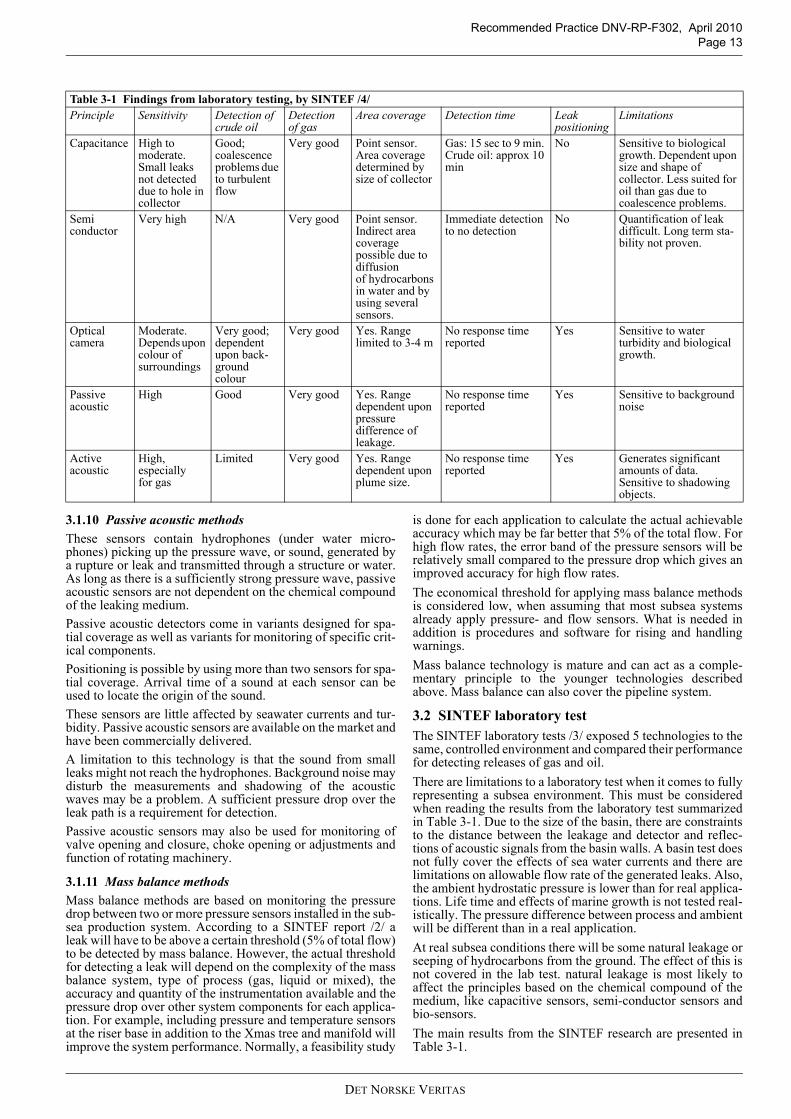
3.2 SINTEF laboratory testThe SINTEF laboratory tests /3/ exposed 5 technologies to thesame, controlled environment and compared their performancefor detecting releases of gas and oil.There are limitations to a laboratory test when it comes to fullyrepresenting a subsea environment. This must be consideredwhen reading the results from the laboratory test summarizedin Table 3-1. Due to the size of the basin, there are constraintsto the distance between the leakage and detector and reflec-tions of acoustic signals from the basin walls. A basin test doesnot fully cover the effects of sea water currents and there arelimitations on allowable flow rate of the generated leaks. Also,the ambient hydrostatic pressure is lower than for real applica-tions. Life time and effects of marine growth is not tested real-istically. The pressure difference between process and ambientwill be different than in a real application.At real subsea conditions there will be some natural leakage orseeping of hydrocarbons from the ground. The effect of this isnot covered in the lab test. natural leakage is most likely toaffect the principles based on the chemical compound of themedium, like capacitive sensors, semi-conductor sensors andbio-sensors.The main results from the SINTEF research are presented inTable 3-1.
Table 3-1 Findings from laboratory testing, by SINTEF /4/Principle Sensitivity Detection of
crude oil Detection of gas
Area coverage Detection time Leak positioning
Limitations
Capacitance High to moderate. Small leaks not detected due to hole in collector
Good;coalescence problems due to turbulent flow
Very good Point sensor. Area coverage determined by size of collector
Gas: 15 sec to 9 min. Crude oil: approx 10 min
No Sensitive to biological growth. Dependent upon size and shape of collector. Less suited for oil than gas due to coalescence problems.
Semi conductor
Very high N/A Very good Point sensor. Indirect area coveragepossible due to diffusionof hydrocarbons in water and by using several sensors.
Immediate detection to no detection
No Quantification of leak difficult. Long term sta-bility not proven.
Optical camera
Moderate. Depends upon colour ofsurroundings
Very good; dependent upon back-ground colour
Very good Yes. Range limited to 3-4 m
No response time reported
Yes Sensitive to water turbidity and biological growth.
Passive acoustic
High Good Very good Yes. Range dependent upon pressure difference of leakage.
No response time reported
Yes Sensitive to background noise
Active acoustic
High, especially for gas
Limited Very good Yes. Range dependent upon plume size.
No response time reported
Yes Generates significant amounts of data. Sensitive to shadowing objects.
DET NORSKE VERITAS

Recommended Practice DNV-RP-F302, April 2010 Page 14
4. Design of subsea leak detection systemsThe design of the leak detection system should be integrated inthe overall subsea system design. According to industry input/5/, the structures where leak detectors have been installed todate are mainly Xmas trees, templates and manifolds. Thefeedback from subsea system integrators /12/ is that integrat-ing the sensors to subsea structures mechanically, and to thecontrol system, in most cases is solvable, but that it is impor-tant that this requirement is identified early in the design proc-ess. The leak detection system should therefore be included asa primary design requirement and not considered as an add-onlate in the design process.
4.1 General requirementsThe leak detection system should as a minimum comply withthe requirements found in ISO 13628-6.The specific contents of the qualification activities must be tai-lored for each technology. DNV-RP-A203 Qualification Pro-cedures for New Technology /15/ may be used as a guidelinefor the qualification process.
4.2 System performance requirements and technol-ogy selectionFor designing an appropriate leak detection system to beapplied for a specific field, performance requirements for thesystem should be developed. The requirements should bebased on:
— authority requirements— environmental and safety risk analysis for the specific field— corporate requirements— field specific conditions that will affect the performance
— interface to the control system — integration into the overall operational management phi-
losophy of the subsea equipment.
A leak detection system comprises selected leak detectiontechnologies as well as tools for data management, operationalprocedures (ref. item 5.1) and layout/placement of sensors.The total system layout should fulfil the developed field spe-cific performance requirements. This is also discussed in theOLF guideline “Recommended procedure for evaluatingremote measuring initiatives” /7/.The selection of sensors must be optimized for each applica-tion. A risk assessment may be valuable to identify the loca-tions on subsea production system where it is most likely thatleakages will occur and hence where to place the detectors. Itis also necessary to take into account process medium, processpressure and external conditions at the site. To enable opera-tors to select the right sensor types for their system, all com-mercial available leak detection technologies should have aspecification sheet specifying parameters like:
— mechanical, electrical and communication interfaces— bandwidth requirements — power requirements— requirements to location and environment (current etc.) — sensitivity to noise and other effects from other compo-
nents — design pressure, design temperature— test conditions, e.g. water depth, pressure and temperature,
for qualification testing and FAT testing— sensitivity and drift— ability to determine location of leak.
Figure 4-1The figure gives an illustration of the process for determining the performance requirements for a subsea leak detection system. In thisfigure it is assumed that the subsea production system is designed in such a way that the probability of large leaks is lower than theprobability of smaller leaks, as indicated by the graph. This assumption is supported by the statistics described in item 2.4 and /1/.
DET NORSKE VERITAS

Recommended Practice DNV-RP-F302, April 2010Page 15
A suggested principal for designing a subsea leak detectionsystem is illustrated by Figure 4-1. The engineering of a subsealeak detection system for a field will involve determining thethresholds A, B and C (Figure 4-1) and required detectiontimes, based on the environmental and safety risk analysis forthe field. Subsequently, the subsea leak detection system is tai-lored based on the specifications of available technologies, thefield specific conditions, connectivity to the control systemand operational management philosophy of the subsea equip-ment. There may be gaps between the desired and achievableperformance of the leak detection system. These gaps may beaddressed by adjustments to the mass balance system or theinspection methods / intervals.As indicated in Figure 4-1, leaks over a certain size C will bedetectable by mass balance and SLD. The smallest leaks, below a threshold A, may not be detectableby any methods. The conditions specific to the field (environment, productionprocess, field layout, fluid composition, etc.) will together withthe performance specifications of the technologies determine thethreshold B between what will be detectable by the leak detec-tion system and what must be detected during inspection. Theinspection interval must be determined from how long a leak ofsize B can be allowed to endure, considering the HSE risk.The target leak regime for the subsea leak detection systemwill be the shaded area in the graph, namely leaks of mediumprobability and between size thresholds B and C. The detectiontime may (depending on technology types) be dependent onthe size of the leak, as indicated by the limit line at leak sizethreshold Y. The general principal is that detection time shouldbe lower for larger leaks in order to reduce the consequencesof the leak.Suggested functional requirements for subsea leak detectionsystems are found in Appendix A.
4.3 Combining technologiesCombining two or more types of sensors may provide moreconfidence in the overall leakage detection system. Comple-mentary sensor technologies should be selected to compensatefor the respective weaknesses and enable indication of a leakevent from one sensor type to be confirmed by positive indica-tions from the other sensor type.One of the selected technologies should be able to performdetection over an area (not be limited to point sensing). Pointsensors may be installed over critical leak points. The downside of combining more sensors can be the additionalcomplexity relating to the subsea control system. In additionthere is the commercial impact of having more detectors topurchase, service and integrate. Further, the scenario of onesensor type triggering a warning and the other not needs to beconsidered.The selection of one sensor type versus two or more should bebased on system integration and performance requirements(ref item 4.2). E.g. in an especially sensitive area where a leak-age of hydrocarbons will have huge safety or environmentalimpact, the additional cost and complexity may be acceptableand even required. In an area where the consequences are less,and it is less likely that leakage will occur, a more simple sen-sor solution may be acceptable.
5. Operating PhilosophyThe objective of this section is to advise on the operation ofsubsea leak detection systems.
5.1 Operating proceduresThe operation should be in line with the principle Detect –Confirm – Act:
— Detect: The subsea detector sends a warning to the topsidecontrol room
— Confirm: The operator checks if the warning is real orfalse according to established procedures
— Act: If the warning is false, the warning is cancelled andan investigation of why the false warning occurred is ini-tiated. If the warning is real, the operator acts according toan emergency preparedness plan on what to do with theoperation of the subsea production system and what to doabout further warning of facility personnel, preparednesspersonnel and authorities
A general approach to how to operate a measuring system isfound in ISO 10012 “Measurement Management Systems –Requirements for Measurement Processes and measuringequipment” /18/.
5.1.1 Warning display and actionMost permanent subsea leak detection principles rely on thesubsea control system to convey the detection of hydrocarbonsto a topside or onshore facility. The signal will trigger a formof warning.It is assumed that a warning signal will either be transformedto an audio or visual warning (e.g. signal lamp), and subse-quently this signal will be observed by a human operator whowill decide on the actions to follow. The maturity of subsea leak detection technologies is today toolow to have an independent safety function. Setting firm limitsfor what detector response represents a positive finding of aleak is challenging. Further investigation of a leakage warningis needed for confirmation and quantification of the leak. Thefurther investigation may include:
— check of parallel systems (e.g. mass balance)— downloading of raw data from the detector giving the
warning for further analysis — inspection on surface visually, by satellite, radar, plane
etc.— inspection subsea e.g. by ROV.
The operator response upon a warning from the leak detectionsystem must be captured in operational procedures for the leakdetection system.
5.2 Sensitivity and response timeField experiences referenced in Appendix C show thatunwanted warnings are frequently experienced with subsealeak detectors. One reason behind this is natural seepage of gasfrom the seabed. Technically, sensitivity and unwanted warn-ings are not independent factors when designing detectors. Asensor designed for high sensitivity to hydrocarbons will moreeasily trigger a warning due to natural seepage. The response time and efficiency of a subsea leak detector willdepend on the sensors technical performance but also on howit is integrated into a system and operated.
5.2.1 Requirements from operatorsA requirement from the operators of subsea leak detection sys-tems is that the number of false warnings is minimized. At thesame time, response time should be as short as possible formajor leaks. To avoid false warnings and maintain operator confidence inleak detection system, a longer response time should beaccepted for small leaks.Specific requirements on response time, allowable leak ratesand released volume (i.e. defining large, medium, small andvery small leaks) should be developed for each field. Theserequirements should be based on a field specific environmentaland safety risk analysis and the emergency preparedness forthe field (see also item 4.2).
DET NORSKE VERITAS
Recommended Practice DNV-RP-F302, April 2010 Page 16
The system should be manned by a trained operator whoknows what the detectors measure and the system limitations.The data display should be of such a quality that it is easy tointerpret for a trained operator.
5.2.2 Findings from laboratory testsThe SINTEF report /3/ describes the response time for sometechnologies during the tests. Please see Table 3-1 for therecorded test results. It should be noted, however, that theseresponse times are found under laboratory conditions andshould not be directly applied for subsea applications.
5.3 Trouble shooting, data download and self diagnosisThe leak detectors have limited field history, and will requireclose follow up in operation. A high data rate transparent com-munication interface will enable the operator to evaluate datafrom the detector, perform fault tracing, download updatedsoftware or even reprocess raw data on topside computers (seealso item 6.3).Detector self diagnosis should be developed for known failuremodes. Redundancy and automatic disabling of componentsshould be implemented to avoid the effect of these failure modes.
6. Installation and interfaces6.1 General The various sensor types will have different requirements forparameters like mechanical interface, required space, powerneeds, communication link bandwidth, etc. Likewise, eachsubsea system will have different capacities available for suchparameters for the leak detection sensors. Procedures for cor-rect installation and positioning of the leak detectors should beavailable for all commercially available technologies.Below, some general guidelines are given for interfacing to thesubsea control system and for testing of a subsea leak detectionsystem, followed by technology specific requirements.
6.2 Communication bandwidthBandwidth capacity for subsea leak detectors is in general alesser challenge for new fields than for retrofit to existingfields. However, bandwidth limitations can be imposed on thesubsea leak detection system depending on the field specificspare bandwidth capacity.
6.3 Communication interfaceThe SIIS (Subsea Instrumentation Interface Standardization) /9/
JIP is an initiative from the industry. The aim is to standardizethe interface between subsea sensors and the subsea control sys-tem. SIIS has developed levels for defining subsea instrumenta-tion interfaces. Referring to the SIIS definition /9/, advanced detectors shouldtypically have a SIIS level 3 interface (Ethernet TCP/IP), whilesimpler or more proven detectors could use a SIIS level 2(CANOPEN fault tolerant, ISO 11898-3) interface. In thefuture, sensors complying with the SIIS standards are what oilcompanies most likely will request and what will be the easiestto interface to their system designs. Please also see item 5.3.
6.4 Power requirementsISO 13628-6 /14/ may serve as a reference for the powerrequirements for subsea leak detectors. Subsea control systems are optimized for power. Thus, keep-ing the power requirements for the subsea leak detection sys-tem to a minimum will always be a benefit.
6.5 Test methodsThe leak detection system should be tested to verify that itmeets the specified functional requirements (ref item 4.2). FAT is described in ISO 13628-6 /14/.System level tests are described in ISO 13628-1 and 13628-6 /14/.Descriptions of sensor specific test methods should be pro-vided by the vendor for all commercially available leak detec-tion systems.
6.6 Technology specific requirements
6.6.1 Active acoustic methodsDue to the active function and high processing demands, someactive acoustic detectors require more bandwidth and powerthan passive acoustic detectors. For size, weight and further technical parameters, please referto Appendix D.
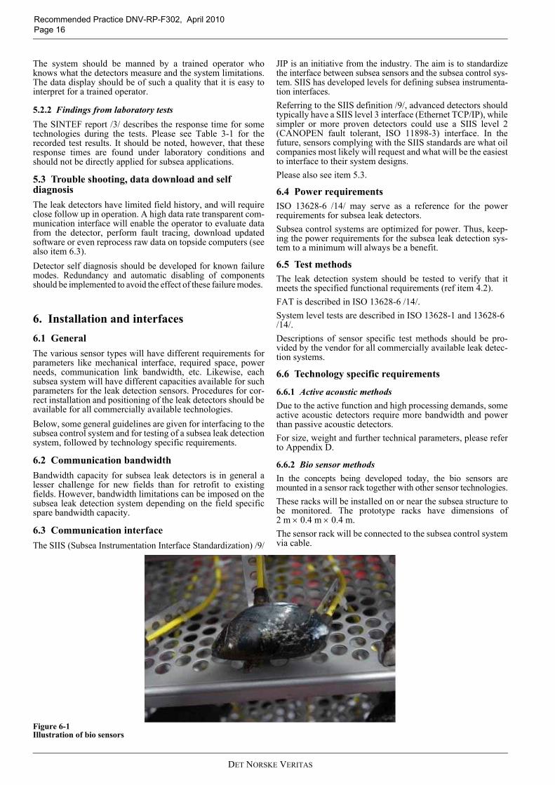
6.6.2 Bio sensor methodsIn the concepts being developed today, the bio sensors aremounted in a sensor rack together with other sensor technologies.These racks will be installed on or near the subsea structure tobe monitored. The prototype racks have dimensions of2 m × 0.4 m × 0.4 m.The sensor rack will be connected to the subsea control systemvia cable.
Figure 6-1Illustration of bio sensors
DET NORSKE VERITAS
Recommended Practice DNV-RP-F302, April 2010Page 17
6.6.3 Capacitance methods Capacitive sensors are point sensors dependant on a hydrocar-bon collector. Typical location of this type of sensor will be bolted on to acollector, typically in the shape of a protection structure, abovean expected leak point. The protection structure is producedout of either steel or composite material or a combination ofthese. In order to collect hydrocarbons, the protection structureneeds to be leak tight. A vent hole to release natural seepagemay be required. Protection covers with several holes or in theshape of grids will not provide the required hydrocarbon col-lection.Retrofit of capacitance sensors may be a challenge since manytemplate covers today are gratings and not solid covers that canbe used for hydrocarbon collection. Solid covers are in generalfound on the NCS and in some British fields. The electrical interface will be via cable. For size, weight and further technical parameters, please referto Appendix D.
6.6.4 Methane sniffer methods
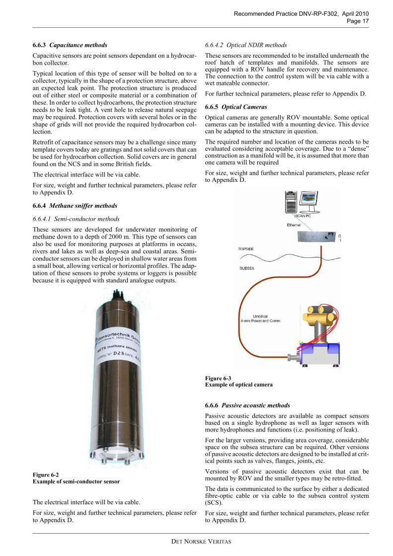
6.6.4.1 Semi-conductor methodsThese sensors are developed for underwater monitoring ofmethane down to a depth of 2000 m. This type of sensors canalso be used for monitoring purposes at platforms in oceans,rivers and lakes as well as deep-sea and coastal areas. Semi-conductor sensors can be deployed in shallow water areas froma small boat, allowing vertical or horizontal profiles. The adap-tation of these sensors to probe systems or loggers is possiblebecause it is equipped with standard analogue outputs.
Figure 6-2Example of semi-conductor sensor
The electrical interface will be via cable. For size, weight and further technical parameters, please referto Appendix D.
6.6.4.2 Optical NDIR methodsThese sensors are recommended to be installed underneath theroof hatch of templates and manifolds. The sensors areequipped with a ROV handle for recovery and maintenance.The connection to the control system will be via cable with awet mateable connector.For further technical parameters, please refer to Appendix D.
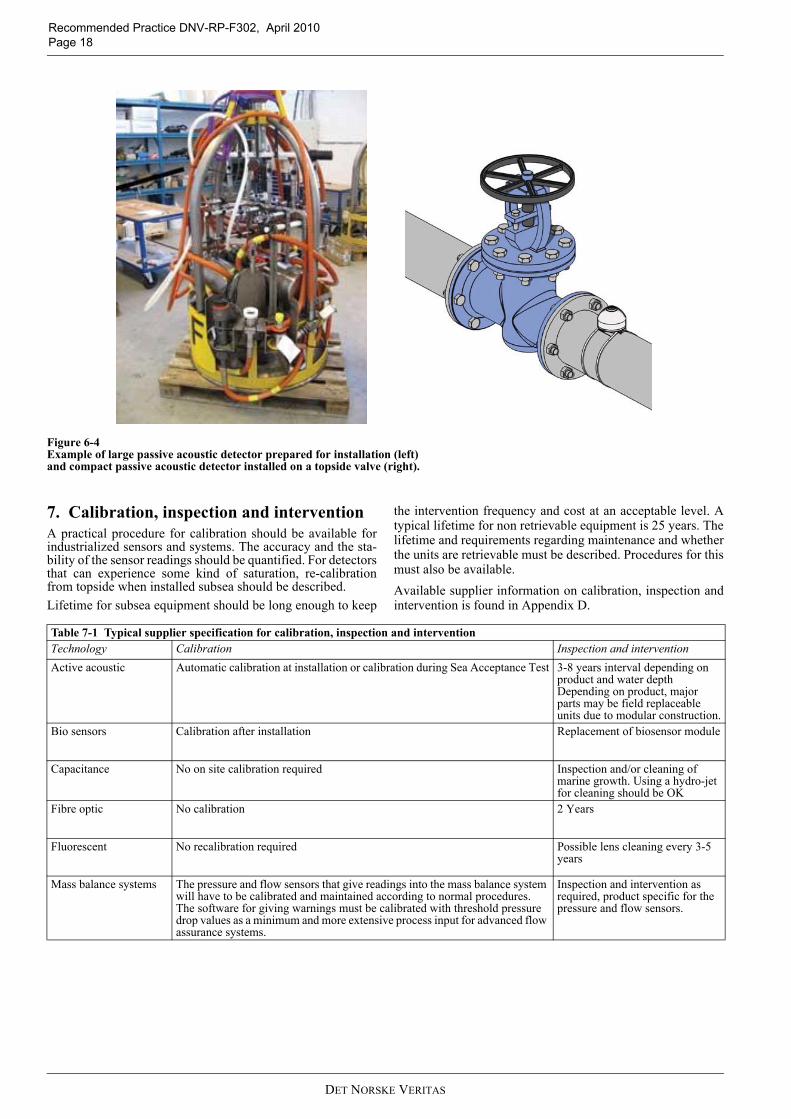
6.6.5 Optical CamerasOptical cameras are generally ROV mountable. Some opticalcameras can be installed with a mounting device. This devicecan be adapted to the structure in question. The required number and location of the cameras needs to beevaluated considering acceptable coverage. Due to a “dense”construction as a manifold will be, it is assumed that more thanone camera will be requiredFor size, weight and further technical parameters, please referto Appendix D.
Figure 6-3Example of optical camera
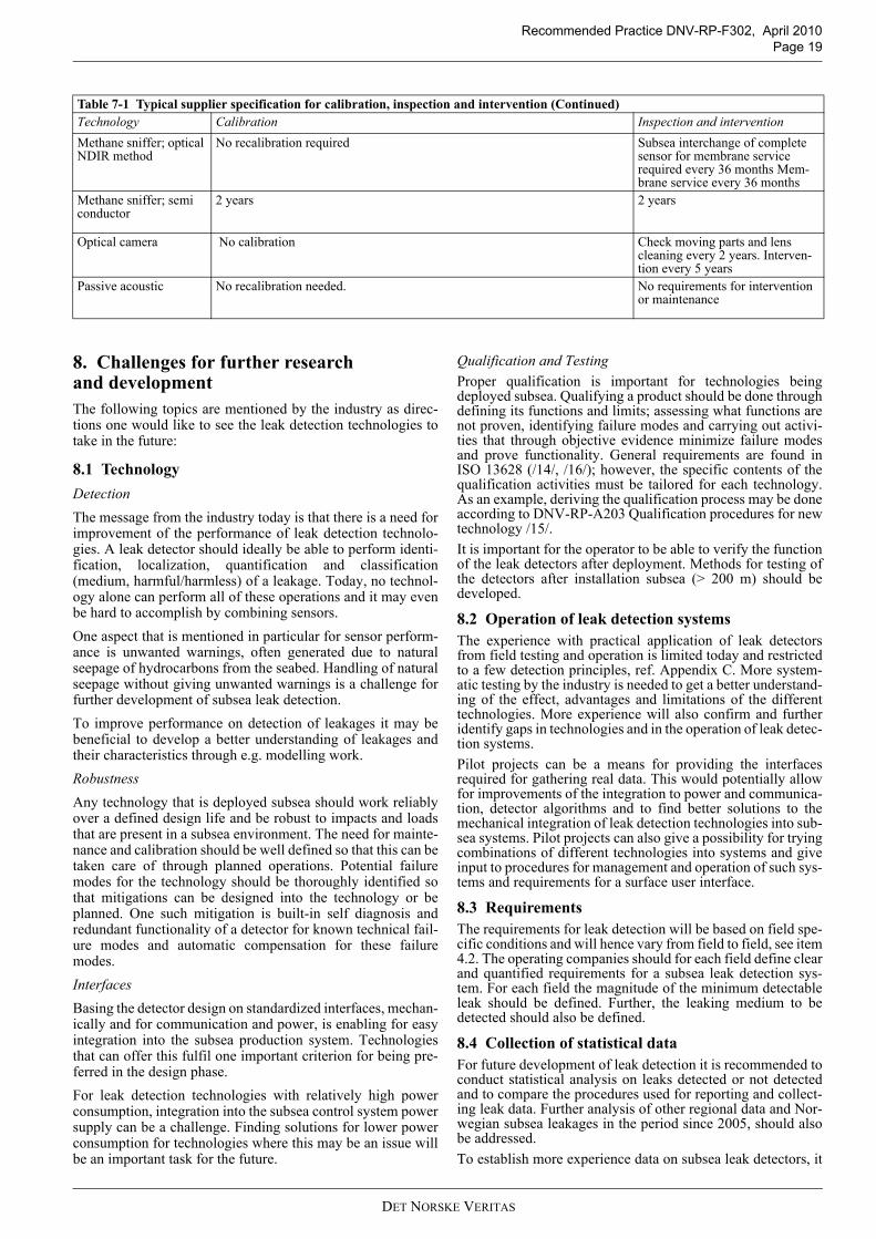
6.6.6 Passive acoustic methodsPassive acoustic detectors are available as compact sensorsbased on a single hydrophone as well as lager sensors withmore hydrophones and functions (i.e. positioning of leak). For the larger versions, providing area coverage, considerablespace on the subsea structure can be required. Other versionsof passive acoustic detectors are designed to be installed at crit-ical points such as valves, flanges, joints, etc.Versions of passive acoustic detectors exist that can bemounted by ROV and the smaller types may be retro-fitted.The data is communicated to the surface by either a dedicatedfibre-optic cable or via cable to the subsea control system(SCS).For size, weight and further technical parameters, please referto Appendix D.
DET NORSKE VERITAS
Recommended Practice DNV-RP-F302, April 2010 Page 18
Figure 6-4Example of large passive acoustic detector prepared for installation (left) and compact passive acoustic detector installed on a topside valve (right).
7. Calibration, inspection and intervention A practical procedure for calibration should be available forindustrialized sensors and systems. The accuracy and the sta-bility of the sensor readings should be quantified. For detectorsthat can experience some kind of saturation, re-calibrationfrom topside when installed subsea should be described.Lifetime for subsea equipment should be long enough to keep
the intervention frequency and cost at an acceptable level. Atypical lifetime for non retrievable equipment is 25 years. Thelifetime and requirements regarding maintenance and whetherthe units are retrievable must be described. Procedures for thismust also be available.Available supplier information on calibration, inspection andintervention is found in Appendix D.
Table 7-1 Typical supplier specification for calibration, inspection and interventionTechnology Calibration Inspection and interventionActive acoustic Automatic calibration at installation or calibration during Sea Acceptance Test 3-8 years interval depending on
product and water depthDepending on product, major parts may be field replaceable units due to modular construction.
Bio sensors Calibration after installation Replacement of biosensor module
Capacitance No on site calibration required Inspection and/or cleaning of marine growth. Using a hydro-jet for cleaning should be OK
Fibre optic No calibration 2 Years
Fluorescent No recalibration required Possible lens cleaning every 3-5 years
Mass balance systems The pressure and flow sensors that give readings into the mass balance system will have to be calibrated and maintained according to normal procedures.The software for giving warnings must be calibrated with threshold pressure drop values as a minimum and more extensive process input for advanced flow assurance systems.
Inspection and intervention as required, product specific for the pressure and flow sensors.
DET NORSKE VERITAS
Recommended Practice DNV-RP-F302, April 2010Page 19
8. Challenges for further research and development The following topics are mentioned by the industry as direc-tions one would like to see the leak detection technologies totake in the future:
8.1 TechnologyDetectionThe message from the industry today is that there is a need forimprovement of the performance of leak detection technolo-gies. A leak detector should ideally be able to perform identi-fication, localization, quantification and classification(medium, harmful/harmless) of a leakage. Today, no technol-ogy alone can perform all of these operations and it may evenbe hard to accomplish by combining sensors.One aspect that is mentioned in particular for sensor perform-ance is unwanted warnings, often generated due to naturalseepage of hydrocarbons from the seabed. Handling of naturalseepage without giving unwanted warnings is a challenge forfurther development of subsea leak detection. To improve performance on detection of leakages it may bebeneficial to develop a better understanding of leakages andtheir characteristics through e.g. modelling work.RobustnessAny technology that is deployed subsea should work reliablyover a defined design life and be robust to impacts and loadsthat are present in a subsea environment. The need for mainte-nance and calibration should be well defined so that this can betaken care of through planned operations. Potential failuremodes for the technology should be thoroughly identified sothat mitigations can be designed into the technology or beplanned. One such mitigation is built-in self diagnosis andredundant functionality of a detector for known technical fail-ure modes and automatic compensation for these failuremodes.InterfacesBasing the detector design on standardized interfaces, mechan-ically and for communication and power, is enabling for easyintegration into the subsea production system. Technologiesthat can offer this fulfil one important criterion for being pre-ferred in the design phase.For leak detection technologies with relatively high powerconsumption, integration into the subsea control system powersupply can be a challenge. Finding solutions for lower powerconsumption for technologies where this may be an issue willbe an important task for the future.
Qualification and TestingProper qualification is important for technologies beingdeployed subsea. Qualifying a product should be done throughdefining its functions and limits; assessing what functions arenot proven, identifying failure modes and carrying out activi-ties that through objective evidence minimize failure modesand prove functionality. General requirements are found inISO 13628 (/14/, /16/); however, the specific contents of thequalification activities must be tailored for each technology.As an example, deriving the qualification process may be doneaccording to DNV-RP-A203 Qualification procedures for newtechnology /15/.It is important for the operator to be able to verify the functionof the leak detectors after deployment. Methods for testing ofthe detectors after installation subsea (> 200 m) should bedeveloped.
8.2 Operation of leak detection systemsThe experience with practical application of leak detectorsfrom field testing and operation is limited today and restrictedto a few detection principles, ref. Appendix C. More system-atic testing by the industry is needed to get a better understand-ing of the effect, advantages and limitations of the differenttechnologies. More experience will also confirm and furtheridentify gaps in technologies and in the operation of leak detec-tion systems.Pilot projects can be a means for providing the interfacesrequired for gathering real data. This would potentially allowfor improvements of the integration to power and communica-tion, detector algorithms and to find better solutions to themechanical integration of leak detection technologies into sub-sea systems. Pilot projects can also give a possibility for tryingcombinations of different technologies into systems and giveinput to procedures for management and operation of such sys-tems and requirements for a surface user interface.
8.3 RequirementsThe requirements for leak detection will be based on field spe-cific conditions and will hence vary from field to field, see item4.2. The operating companies should for each field define clearand quantified requirements for a subsea leak detection sys-tem. For each field the magnitude of the minimum detectableleak should be defined. Further, the leaking medium to bedetected should also be defined.
8.4 Collection of statistical dataFor future development of leak detection it is recommended toconduct statistical analysis on leaks detected or not detectedand to compare the procedures used for reporting and collect-ing leak data. Further analysis of other regional data and Nor-wegian subsea leakages in the period since 2005, should alsobe addressed. To establish more experience data on subsea leak detectors, it
Methane sniffer; optical NDIR method
No recalibration required Subsea interchange of complete sensor for membrane service required every 36 months Mem-brane service every 36 months
Methane sniffer; semi conductor
2 years 2 years
Optical camera No calibration Check moving parts and lens cleaning every 2 years. Interven-tion every 5 years
Passive acoustic No recalibration needed. No requirements for intervention or maintenance
Table 7-1 Typical supplier specification for calibration, inspection and intervention (Continued)Technology Calibration Inspection and intervention
DET NORSKE VERITAS

Recommended Practice DNV-RP-F302, April 2010 Page 20
is recommended that this information is reported throughOREDA (Offshore Reliability Data) /19/, preferably per tech-nology type as described in this document.Learning from history by collection and analysis of successesand failures in operation of subsea leak detection system is rec-
ommended. Such an activity may reveal what parameters thatdrive the successes and failures and enable better managementof these parameters in the future to increase the number of suc-cesses within subsea leak detection.
9. References
/1/ ‘Subsea Leak Experience, Pipelines and Subsea Installations’, ExproSoft, Report no 1611104/1, 2005-01-25, Report for OLF’s leak detection project phase I
/2/ ‘Subsea Leak Detection – Screening of Systems’, SINTEF Petroleumsforskning AS, Report no. 29.6215.00/01/05, 24 November 2006, Report for OLF’s leak detection project phase II
/3/ ‘Subsea Leak Detection Phase 3 – Comparative experimental tests of different detection principles’, SINTEF Petroleumsforskning AS, Report no. 31.6911.00/01/07, 25 September 2007, Report for OLF’s leak detection project phase III
/4/ ‘Technology update on subsea leak detection systems - Input to Subsea Leak Detection Phase 4’ SINTEF report no. 31.6965.00/01/09, 08.05.2009
/5/ Results from industry questionnaire by DNV, March 2009, confidential. Respondents involve regulatory bodies, operators, subsea sys-tem suppliers and subsea leak detector suppliers. Please note that the data collected by this questionnaire cannot be viewed as scientific data.
/6/ www.ptil.no, Petroleum Safety Authority Norway web page/7/ ‘Recommended procedure for evaluating remote measuring initiatives’, OLF guideline no.100, 15.09.04/8/ ‘Bruk av BAT (Beste Tilgjengelige Teknikker) -prinsippet
for miljøsikkerhet (Use of the BAT (Best Available Techniques) principle for environmental safety)’, SINTEF report no. SINTEF A4531, 15.02.2008
/9/ http://www.siis-jip.com/, web site for the Joint Industry Project for Subsea Instrumentation Interface Standardisation/10/ ‘Technology strategy for the Arctic, Extract from the OG21 Strategy’, OG21 document September 2006, http://www.og21.org/filestore/
Strategy_reports/StrategyforArctic.doc/11/ ‘Subsea leak detection. Regulatory and environmental aspects’, Trond Sundby, PSA Norway/12/ OLF seminar on Subsea Leak Detection, Oslo, June 8th and 9th 2009/13/ DNV-RP-F116, ‘Guideline on integrity management of submarine pipeline systems’, 2009/14/ ISO 13628-6:2006(E) ‘Petroleum and natural gas industries – Design and operation of subsea production systems- Part 6: Subsea con-
trol systems’, second edition, 2006-05-15/15/ DNV-RP-A203, ‘Qualification procedures for new technology’, September 2001/16/ ISO 13628-1:2005(E) ‘Petroleum and natural gas industries – Design and operation of subsea production systems- Part 1: General
requirements and recommendations’, second edition, 2005-11-15/17/ ISO 11898 / IEC 61162-400:2001(E) ‘Maritime navigation and radio communication equipment and systems - Digital interfaces - Part
400: Multiple talkers and multiple listeners - Ship systems interconnection - Introduction and general principles’, first edition 2001-11/18/ ISO 10012 ‘Measurement Management Systems – Requirements for Measurement Processes and measuring equipment’, first edition,
2003-04-15 /19/ www.oreda.com, Offshore Reliability Data project web page/20/ ‘Regulations relating to conduct of activities in the petroleum activities (the activities regulations)’, Petroleum Safety Authority Norway
(PSA), 3 September 2001, last amended 21 August 2008/21/ ‘Regulations relating to health, environment and safety in the petroleum activities (the framework regulations)’, Petroleum Safety
Authority Norway (PSA), 31 august 2001, last amended 6 June 2008/22/ ‘Regulations relating to management in the petroleum activities (the management regulations)’, Petroleum Safety Authority Norway
(PSA), 3 September 2001, last amended 21 December 2004./23/ ‘Regulations relating to material and information in the petroleum activities (the information duty regulations)’, Petroleum Safety
Authority Norway (PSA), 3 September 2001, last amended 12 February 2007/24/ ‘Regulations relating to design and outfitting of facilities etc. in the petroleum activities
(the facilities regulations)’, Petroleum Safety Authority Norway (PSA), 3 September 2001, last amended 20 December 2007/25/ 18 AAC 75 ‘Oil and other hazardous substances pollution control’, revised as of October 9, 2008, Department Of Environmental Con-
servation, Alaska/26/ DOT 49 CFR Part 195 ‘Transportation of hazardous liquids by pipeline’, October 1st 2008, Pipeline and Hazardous Materials Safety
Administration/27/ Statutory Instrument 1996 No. 825, ‘The Pipelines Safety Regulations’, 1996, The Health and Safety Executive (HSE), United Kingdom/28/ Council Directive 96/61/EC of 24 September 1996 ‘Concerning Integrated Pollution Prevention And Control’, The Council of The
European Union
DET NORSKE VERITAS
Recommended Practice DNV-RP-F302, April 2010Page 21
APPENDIX A SUGGESTED FUNCTIONAL REQUIREMENTS
FOR SUBSEA LEAK DETECTION SYSTEMS
The list below covers parameters that may be relevant for theperformance of a leak detection system for a particular subseainstallation. This list may be used when identifying the per-formance requirements of such a system. Following from the performance requirements, a leak detec-tion system is designed after evaluating what technologiesmust be chosen and integrated and how the total system mustbe operated to meet these requirements.Note that it is not anticipated that a single technology / princi-ple would be able to detect all of the possible leaks in all pos-sible environments.Functional requirements for subsea leak detection systemsmay include but not be restricted to:
1) Media to be detected:
— multiphase flow (oil/gas/water)— natural Gas— other media that it could be of value to detect:
— produced water— injection water— CO2.
— production chemicals including:
— methanol / MEG— hydraulic fluid – oil based— hydraulic fluid - water based— lube oil— fluorescent dye injected for leak detection.
2) Process operating conditions of the media:
— process pressure— process temperature.
3) Facilities to be monitored to include:
— subsea manifolds— subsea PLEMs, PLETs and riser bases— subsea Xmas trees— subsea processing plants.
4) Environment
— water depth— sea temperature— all year or seasonal ice coverage on water surface.— for dispersion of leaks:
— salinity— sea current.
5) Leak quantification / identification
— detection level / concentration— sensing with some degree of spatial coverage and leakage
localization — independent principles or technologies for confirmation /
verification of leakages.
6) Monitoring frequency
— continuous— permanent/temporary installation.
7) Data availability
— real time communication to host— intermittent download.
8) Design
— high focus on system reliability and remote fault diagnosiscapability in design
— inspection and maintenance requirements to be minimizedby careful material selection and redundancy in design
— critical components to be designed as modules and be eas-ily retrievable to surface by remote (diver less) systems.
DET NORSKE VERITAS

Recommended Practice DNV-RP-F302, April 2010 Page 22
APPENDIX B LEGISLATION
B.1 NORWAYThe Guidelines for the Management Regulations /22/ Section1 and 2 states:“Re Section 1Risk reduction When choosing technical, operational and organisationalsolutions as mentioned in the first paragraph, the responsibleparty should apply principles that provide good inherenthealth, safety and environment properties as the basis for suchselections. See also item 5.4.1 and Appendix A of the ISO17776 standard.Situations of hazard and accident as mentioned in the first par-agraph, constitute a collective term that includes both near-misses and accidents that have occurred, as well as otherunwanted conditions that may cause harm, ref. the FrameworkRegulations Section 9 on principles relating to risk reduction.Barriers as mentioned in the second paragraph, may be phys-ical or non-physical, or a combination thereof. The requirement to independence as mentioned in the thirdparagraph, implies that several important barriers shall not beimpaired or cease to function simultaneously, inter alia as aconsequence of a single failure or a single incident. Re Section 2BarriersThe strategies and principles as mentioned in the first para-graph, should, inter alia, be formulated such that they contrib-ute to giving all involved parties a common understanding ofthe basis for the requirements for the individual barriers,including what connection there is between risk and hazardassessments and the requirements on and to barriers.In order to fulfil the requirement for stipulation of strategiesand principles, the IEC 61508 standard and OLF guidelinesNo. 70 revision 2 should be used for safety systems.Performance as mentioned in the second paragraph, may,inter alia, refer to capacity, reliability, availability, efficiency,ability to withstand loads, integrity and robustness.”The Authority says in the Activities Regulations, section 50:Remote measurement of acute pollution /20/:‘The operator shall establish a remote measurement systemthat provides sufficient information to ensure that acute pollu-tion from the facility is quickly discovered and mapped.’The guideline to section 50 reads:“Remote measurement of acute pollutionRemote measurement means a system that, independent of vis-ibility, light and weather conditions, can discover and mappositions and extent of pollution on the surface of the sea. Sucha system may consist of satellite-based and/or aircraft-basedactive sensors in combination with passive sensors in aero-planes, helicopters, on the facility or vessel during periodswhen visibility and light conditions make this possible. The purpose of the remote measurement is to ensure that theinformation concerning the pollution is sufficient, so that thecorrect actions are taken in order to stop, limit and map thepollution.The system for discovering acute pollution should consist of
a) procedures and systems for visual observation and notifi-cation from facilities, vessels and aircraft,
b) procedures for interpretation of monitoring data from thevarious available sensors,
c) modelling tools to predict transport and spread of acutepollution,
d) procedures for quantifying oil and chemicals with the aidof area measurement and colour thickness maps for therelevant types of oil and chemicals,
e) other meteorological services that are necessary in orderto support the remote measurement,
f) systems for detection of pollution in the recipients.
In order that the remote measurement system shall discoversignificant pollution as mentioned in literas a through f, thearea surrounding the facility should be subjected to remotemeasurement on a regular basis. There should be a plan forremote measurement based on an environmentally orientedrisk analysis, cf. the Management Regulations Section 16 onenvironmentally oriented risk and emergency preparednessanalyses.”A selection of further relevant requirements in the context ofleak detection from the Petroleum Safety Authority Norway isfound below. The list includes examples only and shall not beregarded as complete list of requirements.
B.2 THE EUROPEAN COMMISSIONThe IPPC (Integrated Pollution Prevention and Control) /28/directive of the European Commission is based on 4 main prin-ciples. One of these is BAT – Best Available Techniques. TheIPPC directive shall prevent and limit pollution from industryactivities. Permissions for industrial installation shall be givenfollowing this directive and be based on the BAT principle. BAT is defined as follows:From COUNCIL DIRECTIVE 96/61/EC of 24 September1996:“Best Available Techniques shall mean the most effective and
Framework HSE regulation /21/Section 4 DefinitionsSection 9 Principles relating to risk reductionSection 27 Duty to monitor the external environmentManagement regulation /22/Section 5 Internal requirementsSection 6 Acceptance criteria for major accident risk and envi-
ronmental riskSection 13 General requirements to analysesSection 15 Quantitative risk analyses and emergency prepared-
ness analysesSection 16 Environmentally oriented risk and emergency prepar-
edness analysesInformation duty regulation /23/Section 5 Requirement on consent to certain petroleum activi-
tiesSection 6 Contents of application for consentSection 11 Alert and notification to the supervisory authorities of
situations of hazard and accidentFacilities regulation /24/Section 4 Design of facilitiesSection 7 Safety functionsActivities regulation /20/Section 50 Remote measurement of acute pollution Section 52 Environmental monitoringSection 43 ClassificationFurther information can be found at www.ptil.no
DET NORSKE VERITAS

Recommended Practice DNV-RP-F302, April 2010Page 23
advanced stage in the development of activities and their meth-ods of operation which indicate the practical suitability of par-ticular techniques for providing in principle the basis foremission limit values designed to prevent and, where that is notpracticable, generally to reduce emissions and the impact onthe environment as a whole:- "techniques" shall include both the technology used and theway in which the installation is designed, built, maintained,operated and decommissioned, - "available" techniques shall mean those developed on a scalewhich allows implementation in the relevant industrial sector,under economically and technically viable conditions, takinginto consideration the costs and advantages, whether or notthe techniques are used or produced inside the Member Statein question, as long as they are reasonably accessible to theoperator, - "best" shall mean most effective in achieving a high generallevel of protection of the environment as a whole.” The BAT principle is also referenced in PSA Norway’s Frame-work regulation /21/, section 9, paragraph 2:“In effectuating risk reduction the party responsible shallchoose the technical, operational or organisational solutionswhich according to an individual as well as an overall evalua-tion of the potential harm and present and future use offer thebest results, provided the associated costs are not significantlydisproportionate to the risk reduction achieved.”From the guideline to section 9:“The second paragraph expresses the principle of best availa-ble technology (the BAT principle). This entails that the partyresponsible for the petroleum activities must base its planningand operation on the technology and methods that, based onan overall assessment, produce the best and most effectiveresults.”More information can be found at http://eippcb.jrc.es/http://ec.europa.eu/environment/air/pollutants/stationary/ippc/index.htm
B.3 THE UNITED KINGDOMThe Health and Safety Executive (HSE) in the United King-dom have the Pipelines Safety Regulations [PSR] (SI 1996/825) /27/ as the key regulations concerning pipeline safety andintegrity. There are at present no specific regulations concern-ing subsea production systems. The regulations came intoforce in 1996, replacing earlier prescriptive legislation on themanagement of pipeline safety with a more integrated, goal-setting, risk based approach encompassing both onshore andoffshore pipelines. PSR does not cover the environmentalaspects of accidents arising from pipelines but compliancewith the regulations will help to ensure that a pipeline isdesigned, constructed and operated safely, provide a means ofsecuring pipeline integrity and thereby will contribute byreducing risks to the environment. More specifically in relation to pipeline leak detection sys-tems which are covered (but not explicitly) by Reg. 6 of PSR -Safety systems. The regulation states:“The operator shall ensure that no fluid is conveyed in a pipe-line unless it has been provided with such safety systems as arenecessary for securing that, so far as is reasonably practica-ble, persons are protected from risk to their health & safety.” However, the associated PSR guidance L82 booklet (ISBN 07176 1182 5) states:“36 Safety systems also include leak detection systems wherethey are provided to secure the safe operation of the pipeline.The method chosen for leak detection should be appropriatefor the fluid conveyed and operating conditions.”
HSE Information relating to Pipeline safety and integrity canbe found on the HSE web http://www.hse.gov.uk
B.4 THE UNITED STATESPipeline and Hazardous Materials Safety Administration, DOTPart 195 - Transportation Of Hazardous Liquids By Pipeline /26/§ 195.134 CPM leak detection.“This section applies to each hazardous liquid pipeline trans-porting liquid in single phase (without gas in the liquid). Onsuch systems, each new computational pipeline monitoring(CPM) leak detection system and each replaced component ofan existing CPM system must comply with section 4.2 of API1130 in its design and with any other design criteria addressedin API 1130 for components of the CPM leak detection sys-tem.”§ 195.452 Pipeline integrity management in high consequenceareas.“Leak detection. An operator must have a means to detectleaks on its pipeline system. An operator must evaluate thecapability of its leak detection means and modify, as neces-sary, to protect the high consequence area. An operator’s eval-uation must, at least, consider, the following factors — lengthand size of the pipeline, type of product carried, the pipeline’sproximity to the high consequence area, the swiftness of leakdetection, location of nearest response personnel, leak history,and risk assessment results.”Alaska Department Of Environmental Conservation. 18 AAC75“Oil and Other Hazardous Substances Pollution Control”,Revised as of October 9, 2008 /25/:18 AAC 75.055 Leak detection, monitoring, and operatingrequirements for crude oil transmission pipelines. “(a) A crude oil transmission pipeline must be equipped with aleak detection system capable of promptly detecting a leak,including(1) if technically feasible, the continuous capability to detect adaily dischargeequal to not more than one percent of daily throughput;(2) flow verification through an accounting method, at leastonce every 24 hours;and Register 188, January 2009 ENVIRONMENTAL CON-SERVATION 12(3) for a remote pipeline not otherwise directly accessible,weekly aerial surveillance, unless precluded by safety orweather conditions.(b) The owner or operator of a crude oil transmission pipelineshall ensure that the incoming flow of oil can be completelystopped within one hour after detection of a discharge.(c) If aboveground oil storage tanks are present at the crudeoil transmission pipeline facility, the owner or operator shallmeet the applicable requirements of 18 AAC 75.065, 18 AAC75.066 and 18 AAC 75.075.(d) For facility oil piping connected to or associated with themain crude oil transmissionpipeline, the owner or operator shall meet the requirements of18 AAC 75.080. (Eff. 5/14/92,Register 122; am 12/30/2006, Register 180)18 AAC 75.425. Oil discharge prevention and contingencyplan contents. (a) An oil discharge prevention and contingency plan submit-ted for approval under 18 AAC 75.400 - 18 AAC 75.495 mustbe in a form that is usable as a working plan for oil dischargeprevention, control, containment, cleanup, and disposal. A
DET NORSKE VERITAS
Recommended Practice DNV-RP-F302, April 2010 Page 24
plan must contain enough information, analyses, supportingdata, and documentation to demonstrate the plan holder's abil-ity to meet the requirements of AS 46.04.030 and 18 AAC75.400 - 18 AAC 75.495.(b) The plan for a facility comprised of multiple operations asdescribed at 18 AAC 75.442, must describe, for each categoryof operation at the facility, the appropriate response measuresto meet the applicable portion of the response planning stand-ard.(c) The submitted plan must be accompanied by a cover page(…)(d) The plan must (…)(e) The information in the plan must include(1) Part 1 - Response Action Plan: (…)(2) Part 2 - Prevention Plan: The prevention plan must includea detailed description of all oil discharge prevention measuresand policies employed at the facility, vessel, or operation, withreference to the specific oil discharge risks involved. The pre-vention planmust describe how the applicant meets all the applicablerequirements of 18 AAC 75.005-18 AAC 75.085. The prevention plan may be submitted as aseparate volume, and must include, Register 188, January2009 ENVIRONMENTAL CONSERVATION 119 at a mini-mum, the following information:(A) discharge prevention programs - a description and sched-ule of regular oil discharge prevention, inspection, and main-tenance programs in place at the facility or operation,including(i) oil discharge prevention training programs required by 18AAC 75.020(a);(ii) substance abuse and medical monitoring programsrequired by 18 AAC 75.007(e);(iii) security and surveillance programs required by 18 AAC75.007(f).(B) discharge history -a history of all known oil dischargesgreater than 55 gallons that have occurred at the facility (…)(C) potential discharge analysis - an analysis of potential oildischarges, including size, frequency, cause, duration, andlocation, and a description of actions taken to prevent a poten-tial discharge;(D) specific conditions - a description of(i) any conditions specific to the facility or operation thatmight increase the risk of a discharge, including physical ornavigation hazards, traffic patterns, and other site-specificfactors; and(ii) any measures that have been taken to reduce the risk of adischarge attributable to these conditions, including a sum-mary of operating procedures designed to mitigate the risk ofa discharge;(E) discharge detection - a description of the existing and pro-posed means of discharge detection, including surveillance
schedules, leak detection, observation wells, monitoring sys-tems, and spill-detection instrumentation; if electronic ormechanical instrumentation is employed, detailed specifica-tions, including threshold Register 188, January 2009 ENVI-RONMENTAL CONSERVATION 120 detection, sensitivities,and limitations of equipment must be provided;(F) waivers - (…)(3) Part 3 - Supplemental Information: (…)(4) Part 4 -- Best Available Technology Review: Unless appli-cation of a state requirement would be pre-empted by federallaw, the plan must provide for the use of best available tech-nology consistent with the applicable criteria in 18 AAC75.445(k). In addition, the plan must (A) identify technologies applicable to the applicant's opera-tion that are not subject to response planning or performancestandards specified in 18 AAC 75.445(k)(1) and (2); thesetechnologies include, at a minimum,(i) for all contingency plans, communications described under(1)(D) of this subsection; source control procedures to stop thedischarge at its source and prevent its further spreaddescribed under (1)(F)(i) of this subsection; trajectory analy-ses and forecasts described under (1)(F)(iv) of this subsection;and wildlife capture, treatment, and release procedures andmethods described under (1)(F)(xi) of this subsection;(ii) for a terminal, a crude oil transmission pipeline, or anexploration and production contingency plan: cathodic pro-tection or another approved corrosion control system ifrequired by 18 AAC 75.065(h)(2), (i)(3), or (j)(3); a leak detec-tion system for each tank if required by 18 AAC 75.065(i)(4) or(j)(4);any other prevention or control system approved by thedepartment under 18 AAC 75.065(h)(1)(D); a means of imme-diately determining the liquid level of bulk storage tanks asspecified in 18 AAC 75.065(k)(3) and (4) or in 18 AAC75.066(g)(1)(C) and (D); maintenance practices for buriedmetallic piping containing oil as required by 18 AAC75.080(b); protective coating and cathodic protection ifrequired by 18 AAC 75.080(d) (k)(1),(l) or (m); and corrosionsurveys required by 18 AAC 75.080(k)(2); Register 188, Janu-ary 2009 ENVIRONMENTAL CONSERVATION125(iii) for a tank vessel contingency plan: (…)(iv) for a crude oil transmission pipeline contingency plan:leak detection, monitoring, and operating requirements forcrude oil pipelines that include prompt leak detection asrequired by 18 AAC 75.055(a);(v) for a barge contingency plan: (…)(vi) for a railroad tank car contingency plan (…)(B) for each applicable technology under (A) of this para-graph, identify all available technologies and include a writtenanalysis of each technology, using the applicable criteria in 18AAC 75.445(k)(3); and(C) include a written justification that the technology proposedto be used is the best available for the applicant's operation.”
DET NORSKE VERITAS

Recommended Practice DNV-RP-F302, April 2010Page 25
APP
EN
DIX
C
SUB
SEA
LE
AK
DE
TE
CT
ION
INST
AL
LE
D B
ASE
Tabl
e C
-1 S
ubse
a L
eak
Det
ecto
rs -
Inst
alle
d B
ase
(The
dat
a be
low
is c
olle
cted
from
the
field
ope
rato
rs. T
he d
ata
is p
rovi
ded
as in
form
atio
n on
ly, n
o qu
ality
che
ck o
f the
dat
a ha
s bee
n pe
rfor
med
)Fi
eld
Ope
rato
rLe
ak d
etec
-tio
n te
chno
l-og
y
# se
nsor
s de
liver
edIn
stal
led
year
Inst
alle
d on
st
ruct
ure
How
is th
e da
ta
from
the
tech
nol-
ogy
man
aged
/ in
tegr
ated
in y
our
oper
atio
n?
Det
ecto
rs
still
in u
se?
Leak
s ide
ntifi
ed
by th
e te
chno
l-og
y? P
leas
e de
scrib
e
Hav
e yo
u ha
d le
aks t
hat t
he
tech
nolo
gy d
id
not d
etec
t?
Plea
se d
escr
ibe
Fals
e al
arm
s?
Oth
er fa
ilure
m
odes
? Pl
ease
de
scrib
e
Parti
cula
r ch
alle
nges
?C
omm
ents
, ex
perie
nces
Alv
eSt
atoi
lC
apac
itanc
e1
2009
XM
TC
ontro
l sys
tem
yes
No
No
yes
subs
ea
test
ing
Dra
ugen
Shel
lC
apac
itanc
e3
1993
XM
T
yes
yes
test
ing
*ven
t hol
es o
n pr
o-te
ctio
n st
ruct
ure
*dur
ing
com
mis
-si
onin
g th
ey d
idn'
t gi
ve p
ositi
ve si
gnal
du
ring
test
ing
(hyd
raul
ic fl
uid
bein
g inj
ecte
d in
the
vici
nity
)*t
hey
wer
e th
en
pulle
d an
d te
sted
in
a hy
perb
aric
cha
m-
ber,
whe
re th
ey
wor
ked
*no
firm
con
clu-
sion
,G
ullfa
ks
Stat
oil
Cap
acita
nce
13
Gul
lfaks
St
atoi
lPa
ssiv
e ac
oust
ic
(sm
all)
Hei
drun
NF
Stat
oil
Cap
acita
nce
All
12
wel
ls20
01FC
Mas
ala
rm i
SAS
All
in u
se
but t
wo
of
them
giv
es
alar
ms c
on-
tinou
sly
due
to sh
al-
low
gas
.
No
No
Man
y fa
lse
alar
ms d
ue to
sh
allo
w g
as in
ar
ea
Hei
drun
Sa
telit
eSt
atoi
lO
ptic
al c
am-
era
20
09B
rack
et
on G
uide
-po
st
vide
o on
web
br
owse
r Pr
esen
tly
out o
f ord
erN
oN
o
Pr
esen
tly o
ut o
f or
der d
ue to
ear
t fa
ult.
Cam
era
is
retri
eved
, but
will
be
inst
alle
d af
ter
refu
rbis
hmen
t.
DET NORSKE VERITAS
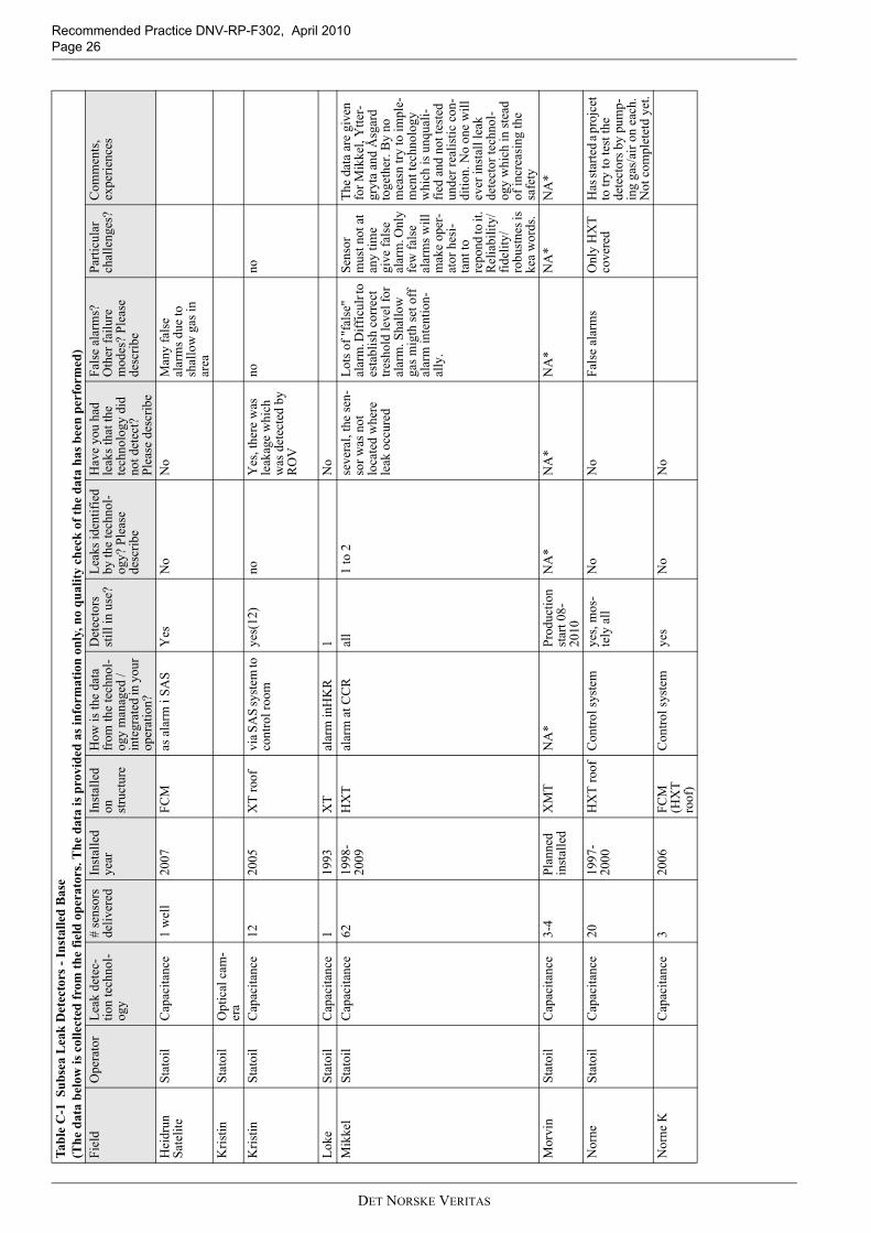
Recommended Practice DNV-RP-F302, April 2010 Page 26
Hei
drun
Sa
telit
eSt
atoi
lC
apac
itanc
e1
wel
l20
07FC
Mas
ala
rm i
SAS
Yes
No
No
Man
y fa
lse
alar
ms d
ue to
sh
allo
w g
as in
ar
ea
Kris
tinSt
atoi
lO
ptic
al c
am-
era
Kris
tinSt
atoi
lC
apac
itanc
e12
2005
XT
roof
via S
AS
syst
em to
co
ntro
l roo
mye
s(12
)no
Yes
, the
re w
as
leak
age
whi
ch
was
det
ecte
d by
R
OV
nono
Loke
Stat
oil
Cap
acita
nce
119
93X
Tal
arm
inH
KR
1
No
M
ikke
lSt
atoi
lC
apac
itanc
e62
1998
-20
09H
XT
alar
m a
t CC
Ral
l1
to 2
seve
ral,
the
sen-
sor w
as n
ot
loca
ted
whe
re
leak
occ
ured
Lots
of "
fals
e"
alar
m. D
iffic
ulr t
o es
tabl
ish
corr
ect
tresh
old
leve
l for
al
arm
. Sha
llow
ga
s mig
th se
t off
al
arm
inte
ntio
n-al
ly.
Sens
or
mus
t not
at
any
time
give
fals
e al
arm
. Onl
y fe
w fa
lse
alar
ms w
ill
mak
e op
er-
ator
hes
i-ta
nt to
re
pond
to it
. R
elia
bilit
y/fid
elity
/ro
bust
nes i
s ke
a w
ords
.
The
data
are
giv
en
for M
ikke
l, Y
tter-
gryt
a an
d Å
sgar
d to
geth
er. B
y no
m
easn
try
to im
ple-
men
t tec
hnol
ogy
whi
ch is
unq
uali-
fied
and
not t
este
d un
der r
ealis
tic c
on-
ditio
n. N
o on
e w
ill
ever
inst
all l
eak
dete
ctor
tech
nol-
ogy
whi
ch in
stea
d of
incr
easi
ng th
e sa
fety
Mor
vin
Stat
oil
Cap
acita
nce
3-4
Plan
ned
inst
alle
dX
MT
NA
*Pr
oduc
tion
star
t 08-
2010
NA
*N
A*
NA
*N
A*
NA
*
Nor
neSt
atoi
lC
apac
itanc
e20
1997
-20
00H
XT
roof
Con
trol s
yste
mye
s, m
os-
tely
all
No
No
Fals
e al
arm
sO
nly
HX
T co
vere
dH
as st
arte
d a pr
ojce
t to
try
to te
st th
e de
tect
ors b
y pu
mp-
ing
gas/
air o
n ea
ch.
Not
com
plet
etd
yet.
Nor
ne K
C
apac
itanc
e3
2006
FCM
(H
XT
roof
)
Con
trol s
yste
mye
sN
oN
o
Tabl
e C
-1 S
ubse
a L
eak
Det
ecto
rs -
Inst
alle
d B
ase
(The
dat
a be
low
is c
olle
cted
from
the
field
ope
rato
rs. T
he d
ata
is p
rovi
ded
as in
form
atio
n on
ly, n
o qu
ality
che
ck o
f the
dat
a ha
s bee
n pe
rfor
med
)Fi
eld
Ope
rato
rLe
ak d
etec
-tio
n te
chno
l-og
y
# se
nsor
s de
liver
edIn
stal
led
year
Inst
alle
d on
st
ruct
ure
How
is th
e da
ta
from
the
tech
nol-
ogy
man
aged
/ in
tegr
ated
in y
our
oper
atio
n?
Det
ecto
rs
still
in u
se?
Leak
s ide
ntifi
ed
by th
e te
chno
l-og
y? P
leas
e de
scrib
e
Hav
e yo
u ha
d le
aks t
hat t
he
tech
nolo
gy d
id
not d
etec
t?
Plea
se d
escr
ibe
Fals
e al
arm
s?
Oth
er fa
ilure
m
odes
? Pl
ease
de
scrib
e
Parti
cula
r ch
alle
nges
?C
omm
ents
, ex
perie
nces
DET NORSKE VERITAS

Recommended Practice DNV-RP-F302, April 2010Page 27
Orm
en
Lang
eSh
ell
Pass
ive
acou
stic
3
At e
ach
tem
plat
e
2
out o
f 3 u
nits
re
turn
ed to
shor
e for
re
plac
amen
t of
hydr
opho
nes d
ue to
co
ntru
ctio
n er
ror.
The t
hird
uni
t is c
ol-
lect
ing
data
but
will
al
so n
eed
to g
et th
e hy
drop
hone
s re
plac
ed.
Rim
faks
, Sk
infa
ks
Stat
oil
Cap
acita
nce
12
Urd
Stat
oil
Cap
acita
nce
820
05-
2006
XM
TC
ontro
l sys
tem
yes
No
No
yes
subs
ea te
st-
ing
UM
C N
orth
C
orm
oran
t Sh
ell
Cap
acita
nce
Sigy
n St
atoi
lC
apac
itanc
e3
2002
XT
alar
m in
HK
R3
N
o
Skar
vB
P N
orge
Cap
acita
nce
XM
T an
d m
anifo
ld
Slei
pner
V
est S
VA
NSt
atoi
lC
apac
itanc
e4
2004
XT
alar
m in
HK
R4
N
o
Slei
pner
Øst
SL
ØSt
atoi
lC
apac
itanc
e2
1993
XT
alar
m in
HK
R2
N
o
Snor
re U
PASt
atoi
lC
apac
itanc
e4
Firs
t in
stal
la-
tion 1
992.
La
st is
tal-
latio
n af
ter
repa
ir 20
08
Yes
, 2
dete
ctor
s ab
ove
each
ot
her i
n ea
ch e
nd
of th
e pr
otec
-tio
n ro
of
Ala
rm o
n op
era-
tion
scre
en. S
ig-
nal t
hrou
gh th
e su
bsea
con
trole
sy
stem
4Th
e det
ecto
rs ar
e pl
ace
up u
nder
th
e co
llect
ion
roof
and
we h
ave
dete
cted
col
lec-
tion
of n
on-w
ater
No,
but
har
d to
sa
y fo
r sur
eIt
has b
een
very
di
ffic
ult t
o m
ake
thes
e de
tect
or
wor
k pro
perly
. So
we
don'
t kno
w if
it
is a
inst
rum
ent
failu
re o
r not
The
chal
-la
nge
has
been
to
mak
e th
is
dete
ctor
s w
ork
prop
-er
ly. T
here
is
no
poss
i-bi
lity
to se
e if
ther
e is
oi
l or g
as
colle
cted
un
der t
he
roof
by
RO
V.
The
Snor
re S
PS is
co
vere
d by
a ro
of
that
can
col
lect
as
muc
h as
40m
3 of
sp
illed
hydr
aulic
oil,
gas a
nd/o
r hyd
ro-
carb
. It i
s pos
sibl
e to
em
ty th
e ro
of to
th
e Sn
orre
Pla
tt-fo
rm b
y us
e of
the
3" se
rvis
e lin
es. I
t is
not p
ossi
ble
to c
on-
firm
that
the
roof
is
empt
Tabl
e C
-1 S
ubse
a L
eak
Det
ecto
rs -
Inst
alle
d B
ase
(The
dat
a be
low
is c
olle
cted
from
the
field
ope
rato
rs. T
he d
ata
is p
rovi
ded
as in
form
atio
n on
ly, n
o qu
ality
che
ck o
f the
dat
a ha
s bee
n pe
rfor
med
)Fi
eld
Ope
rato
rLe
ak d
etec
-tio
n te
chno
l-og
y
# se
nsor
s de
liver
edIn
stal
led
year
Inst
alle
d on
st
ruct
ure
How
is th
e da
ta
from
the
tech
nol-
ogy
man
aged
/ in
tegr
ated
in y
our
oper
atio
n?
Det
ecto
rs
still
in u
se?
Leak
s ide
ntifi
ed
by th
e te
chno
l-og
y? P
leas
e de
scrib
e
Hav
e yo
u ha
d le
aks t
hat t
he
tech
nolo
gy d
id
not d
etec
t?
Plea
se d
escr
ibe
Fals
e al
arm
s?
Oth
er fa
ilure
m
odes
? Pl
ease
de
scrib
e
Parti
cula
r ch
alle
nges
?C
omm
ents
, ex
perie
nces
DET NORSKE VERITAS
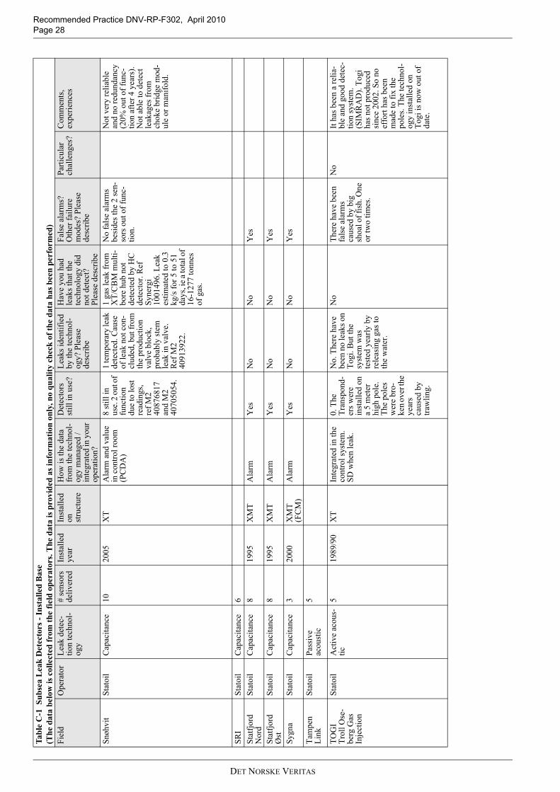
Recommended Practice DNV-RP-F302, April 2010 Page 28
Snøh
vit
Stat
oil
Cap
acita
nce
1020
05X
TA
larm
and
val
ue
in c
ontro
l roo
m
(PC
DA
)
8 st
ill in
us
e. 2
out
of
func
tion
due
to lo
st
read
ings
, re
f M2
4087
6817
an
d M
2 40
7050
54.
1 te
mpo
rary
leak
de
tect
ed. C
ause
of
leak
not
con
-cl
uded
, but
from
th
e pr
oduc
tion
valv
e bl
ock,
pr
obab
ly st
em
leak
in v
alve
. R
ef M
2 40
9139
22.
1 ga
s lea
k fr
om
XT/
CB
M m
ulti-
bore
hub
not
de
tect
ed b
y H
C
dete
ctor
. Ref
Sy
nerg
i 10
0149
6. L
eak
estim
ated
to 0
.3
kg/s
for 5
to 5
1 da
ys, i
e a to
tal o
f 16
-127
7 to
nnes
of
gas
.
No
fals
e al
arm
s be
side
s the
2 se
n-so
rs o
ut o
f fun
c-tio
n.
N
ot v
ery
relia
ble
and
no re
dund
ancy
(2
0% o
ut o
f fun
c-tio
n af
ter 4
yea
rs).
Not
abl
e to
det
ect
leak
ages
from
ch
oke
brid
ge m
od-
ule
or m
anifo
ld.
SRI
Stat
oil
Cap
acita
nce
6
Stat
fjord
N
ord
Stat
oil
Cap
acita
nce
819
95X
MT
Ala
rmY
esN
oN
oY
es
Stat
fjord
Ø
stSt
atoi
lC
apac
itanc
e8
1995
XM
TA
larm
Yes
No
No
Yes
Sygn
aSt
atoi
lC
apac
itanc
e3
2000
XM
T(F
CM
)A
larm
Yes
No
No
Yes
Tam
pen
Link
Stat
oil
Pass
ive
acou
stic
5
TOG
I Tr
oll O
se-
berg
Gas
In
ject
ion
Stat
oil
Act
ive
acou
s-tic
519
89/9
0X
TIn
tegr
ated
in th
e co
ntro
l sys
tem
. SD
whe
n le
ak.
0. T
he
Tran
spon
d-er
s wer
e in
stal
led
on
a 5
met
er
high
pol
e.
The
pole
s w
ere
bro-
ken o
ver t
he
year
s ca
used
by
traw
ling.
No.
The
re h
ave
been
no
leak
s on
Togi
. But
the
syst
em w
as
test
ed y
early
by
rele
asin
g ga
s to
the
wat
er.
No
Ther
e ha
ve b
een
fals
e al
arm
s ca
used
by
big
shoa
l of f
ish.
One
or
two
times
.
No
It ha
s bee
n a
relia
-bl
e an
d go
od d
etec
-tio
n sy
stem
. (S
IMR
AD
). To
gi
has n
ot p
rodu
ced
sinc
e 20
02. S
o no
ef
fort
has b
een
mad
e to
fix
the
pole
s. Th
e te
chno
l-og
y in
stal
led
on
Togi
is n
ow o
ut o
f da
te.
Tabl
e C
-1 S
ubse
a L
eak
Det
ecto
rs -
Inst
alle
d B
ase
(The
dat
a be
low
is c
olle
cted
from
the
field
ope
rato
rs. T
he d
ata
is p
rovi
ded
as in
form
atio
n on
ly, n
o qu
ality
che
ck o
f the
dat
a ha
s bee
n pe
rfor
med
)Fi
eld
Ope
rato
rLe
ak d
etec
-tio
n te
chno
l-og
y
# se
nsor
s de
liver
edIn
stal
led
year
Inst
alle
d on
st
ruct
ure
How
is th
e da
ta
from
the
tech
nol-
ogy
man
aged
/ in
tegr
ated
in y
our
oper
atio
n?
Det
ecto
rs
still
in u
se?
Leak
s ide
ntifi
ed
by th
e te
chno
l-og
y? P
leas
e de
scrib
e
Hav
e yo
u ha
d le
aks t
hat t
he
tech
nolo
gy d
id
not d
etec
t?
Plea
se d
escr
ibe
Fals
e al
arm
s?
Oth
er fa
ilure
m
odes
? Pl
ease
de
scrib
e
Parti
cula
r ch
alle
nges
?C
omm
ents
, ex
perie
nces
DET NORSKE VERITAS

Recommended Practice DNV-RP-F302, April 2010Page 29
Tord
is
Stat
oil
Cap
acita
nce
19
94
Tord
is fi
eld
was
in
stal
led
with
hy
droc
arbo
n de
tect
ors,
but
thes
e w
ere
aban
-do
ned
due
to
man
y fa
lse
alar
ms.
Tord
is IO
RSt
atoi
lPa
ssiv
e ac
oust
ic3
2007
SSB
I (s
ubse
a se
para
tor)
Still
not
wor
king
, m
odul
es o
nsho
re
for t
estin
g ve
rifi-
catio
n
No,
will
be
re-in
stal
led
whe
n re
ady.
No
No
No
Def
inin
g th
e di
ffer
-en
t lea
k se
ctor
s.
New
inst
alla
tions
at
T&V
fiel
ds w
ith
acou
stic
sens
ors
seem
to sh
ow so
me
prog
ress
, but
still
in
thei
r inf
ancy
. Mos
t lik
ely
the
way
for-
war
d.Tr
oll P
ilot
Stat
oil
Pass
ive
acou
stic
not p
er-
man
ent
inst
alla
-tio
n
Tyrih
ans
Stat
oil
Cap
acita
nce
420
08 -
2009
XT-
Roo
fD
ata
from
the
sens
or a
re se
nt to
co
ntro
l roo
m.
War
ning
s sho
wn
in c
ontro
l roo
m
42
leak
s dur
ing
star
t-up
of w
ells
du
e to
shal
low
ga
s.
Non
eSh
allo
w g
asN
one
Onl
y 4
of 1
2 w
ells
in
pro
dukt
ion
Veg
aSt
atoi
lPa
ssiv
e ac
oust
ic0
Plan
ned
inst
alle
dN
A*
NA
*N
A*
NA
*N
A*
NA
*N
A*
NA
*
Vig
dis
Stat
oil
Pass
ive
acou
stic
120
08m
anifo
ldSe
ctor
ala
rms
back
to C
R if
no
ises
exp
eri-
ence
d
yes
No
No
Yes
. Dur
ing
ves-
sel o
pera
tions
at
othe
r loc
atio
ns a
t th
e fie
ld. T
unin
g of
the
syst
em
whe
n in
stal
led
impo
rtant
for
build
ing
conf
i-de
nce
in th
e sy
s-te
m. F
alse
ala
rms
low
er th
e co
nfi-
denc
e fo
r the
sys-
tem
.
Def
inin
g th
e di
ffer
-en
t lea
k se
ctor
s.
Ym
e St
atoi
lC
apac
itanc
e2
Tabl
e C
-1 S
ubse
a L
eak
Det
ecto
rs -
Inst
alle
d B
ase
(The
dat
a be
low
is c
olle
cted
from
the
field
ope
rato
rs. T
he d
ata
is p
rovi
ded
as in
form
atio
n on
ly, n
o qu
ality
che
ck o
f the
dat
a ha
s bee
n pe
rfor
med
)Fi
eld
Ope
rato
rLe
ak d
etec
-tio
n te
chno
l-og
y
# se
nsor
s de
liver
edIn
stal
led
year
Inst
alle
d on
st
ruct
ure
How
is th
e da
ta
from
the
tech
nol-
ogy
man
aged
/ in
tegr
ated
in y
our
oper
atio
n?
Det
ecto
rs
still
in u
se?
Leak
s ide
ntifi
ed
by th
e te
chno
l-og
y? P
leas
e de
scrib
e
Hav
e yo
u ha
d le
aks t
hat t
he
tech
nolo
gy d
id
not d
etec
t?
Plea
se d
escr
ibe
Fals
e al
arm
s?
Oth
er fa
ilure
m
odes
? Pl
ease
de
scrib
e
Parti
cula
r ch
alle
nges
?C
omm
ents
, ex
perie
nces
DET NORSKE VERITAS

Recommended Practice DNV-RP-F302, April 2010 Page 30
Ytte
rgry
taSt
atoi
lC
apac
itanc
eSe
e M
ikke
lSe
e M
ikke
lSe
e M
ikke
lSe
e M
ikke
lSe
e M
ikke
lSe
e M
ikke
lSe
e M
ikke
lSe
e M
ikke
lSe
e M
ikke
lSe
e M
ikke
l
Åsg
ard
Stat
oil
Cap
acita
nce
See
Mik
kel
See
Mik
kel
See
Mik
kel
See
Mik
kel
See
Mik
kel
See
Mik
kel
See
Mik
kel
See
Mik
kel
See
Mik
kel
See
Mik
kel
Åsg
ard
Stat
oil
Opt
ical
cam
-er
a
va
lve
* N
A =
Not
App
licab
le
Tabl
e C
-1 S
ubse
a L
eak
Det
ecto
rs -
Inst
alle
d B
ase
(The
dat
a be
low
is c
olle
cted
from
the
field
ope
rato
rs. T
he d
ata
is p
rovi
ded
as in
form
atio
n on
ly, n
o qu
ality
che
ck o
f the
dat
a ha
s bee
n pe
rfor
med
)Fi
eld
Ope
rato
rLe
ak d
etec
-tio
n te
chno
l-og
y
# se
nsor
s de
liver
edIn
stal
led
year
Inst
alle
d on
st
ruct
ure
How
is th
e da
ta
from
the
tech
nol-
ogy
man
aged
/ in
tegr
ated
in y
our
oper
atio
n?
Det
ecto
rs
still
in u
se?
Leak
s ide
ntifi
ed
by th
e te
chno
l-og
y? P
leas
e de
scrib
e
Hav
e yo
u ha
d le
aks t
hat t
he
tech
nolo
gy d
id
not d
etec
t?
Plea
se d
escr
ibe
Fals
e al
arm
s?
Oth
er fa
ilure
m
odes
? Pl
ease
de
scrib
e
Parti
cula
r ch
alle
nges
?C
omm
ents
, ex
perie
nces
Tabl
e C
-2 S
ubse
a L
eak
Det
ecto
rs -
Fiel
ds w
ith n
o le
ak d
etec
tion
inst
alle
d Fi
eld
Ope
rato
rFr
am V
est/Ø
stSt
atoi
lH
eidr
un V
IKS
Stat
oil
Njo
rdSt
atoi
lO
sebe
rg D
elta
Stat
oil
Ose
berg
Ves
tflan
ken
Stat
oil
Ose
berg
Sør
KSt
atoi
lO
sebe
rg S
ør J
Stat
oil
Skirn
e/B
yggv
eSt
atoi
l on
beho
lf of
Tot
alSn
orre
BSt
atoi
lTr
oll B
and
C.
Stat
oil
Tune
Stat
oil
Val
eSt
atoi
lV
ilje
Stat
oil
DET NORSKE VERITAS
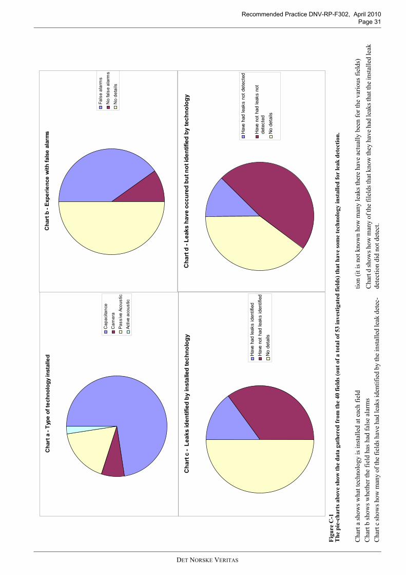
Recommended Practice DNV-RP-F302, April 2010Page 31
Figu
re C
-1
The
pie
-cha
rts a
bove
show
the
data
gat
here
d fr
om th
e 40
fiel
ds (o
ut o
f a to
tal o
f 53
inve
stig
ated
fiel
ds) t
hat h
ave
som
e te
chno
logy
inst
alle
d fo
r le
ak d
etec
tion.
Cha
rt a
show
s wha
t tec
hnol
ogy
is in
stal
led
at e
ach
field
Cha
rt b
show
s whe
ther
the
field
has
had
fals
e al
arm
sC
hart
c sh
ows h
ow m
any
of th
e fie
lds h
ave
had
leak
s ide
ntifi
ed b
y th
e in
stal
led
leak
det
ec-
tion
(it is
not
kno
wn
how
man
y le
aks t
here
hav
e ac
tual
ly b
een
for t
he v
ario
us fi
elds
)C
hart
d sh
ows h
ow m
any
of th
e file
lds t
hat k
now
they
hav
e had
leak
s tha
t the
inst
alle
d le
akde
tect
ion
did
not d
etec
t.Cha
rt b
- Ex
perie
nce
with
fals
e al
arm
s
Fals
e al
arm
s
No
fals
e al
arm
s
No
deta
ils
Cha
rt c
- Le
aks
iden
tifie
d by
inst
alle
d te
chno
logy
Hav
e ha
d le
aks
iden
tifie
dH
ave
not h
ad le
aks
iden
tifie
dN
o de
tails
Cha
rt d
- Lea
ks h
ave
occu
red
but n
ot id
entif
ied
by te
chno
logy
Hav
e ha
d le
aks
not d
etec
ted
Hav
e no
t had
leak
s no
tde
tect
edN
o de
tails
Cha
rt a
- Ty
pe o
f tec
hnol
ogy
inst
alle
d
Cap
acita
nce
Cam
era
Pas
sive
Aco
ustic
Activ
e ac
oust
ic
DET NORSKE VERITAS

Recommended Practice DNV-RP-F302, April 2010 Page 32
- -
APP
EN
DIX
D
SUB
SEA
LE
AK
DE
TE
CT
OR
S SU
PPL
IER
TE
CH
NIC
AL
DA
TA
Tabl
e D
-1 D
etec
tors
- Su
pplie
r Te
chni
cal D
ata
Tech
-no
logy
Cal
ibra
-tio
n/R
e-ca
li-br
atio
n
Mai
nte-
nanc
eM
echa
ni-
cal i
nter
-fa
ce
Wei
ght
[kg]
Dim
ensi
ons
Con
nec-
tion
to
pow
er
and
com
-m
unic
a-tio
n
Pow
er
need
Ban
d-w
idth
ne
ed
Mat
urity
1D
etec
tabl
e re
leas
e lim
it or
oth
er a
ccu-
racy
info
rmat
ion
Det
ecta
ble
med
iaD
etec
tion
rang
eR
elia
bil-
ity d
ata
2D
esig
n lif
e [y
ears
]
Wat
er
dept
h [m
]
Tem
-pe
ra-
ture
[°
C]
Act
ive
acou
stic
Cal
ibra
-tio
n du
r-in
g Se
a A
ccep
t-an
ce T
est
3-5
year
s in
terv
al
Mou
nted
on
RO
V
skid
or
dire
ctly
to
tem
plat
e st
ruct
ure.
W
ill b
e de
sign
ed to
be
RO
V
retie
vabl
e.
Rec
eive
ar
ray 9
.6
(dry
),su
bsea
bo
ttle
24.8
(d
ry),
trans
mit
arra
y 4.5
(d
ry),
Rec
eive
r: 10
2 x
496
x 13
1mm
Tran
smit-
ter:
240
x 86
x
99m
mSu
bsea
B
ottle
: 53
0.9
x 17
4mm
48V
, Et
hern
et40
W -
100W
Hig
h,
deve
lop-
men
t go
al is
1- 10
Mbi
t et
hern
et
inte
rfac
e
Bas
elin
e of
fsho
re
prod
uct:
Com
mer
-ci
ally
del
iv-
ered
.Su
bsea
ver
-si
on: C
on-
cept
Smal
l gas
leak
ages
(0
.35
mm
noz
zle,
2
bar p
ress
ure
diff
er-
ence
) det
ecte
d at
ab
out 3
0 m
eter
s. Fl
uid l
eak f
rom
5mm
no
zzle
with
15b
ar
pres
sure
diff
eren
ce
dete
cted
at 5
0m
Not
dep
end-
ent o
n ch
em-
ical
co
mpo
und a
s lo
ng a
s ac
oust
ic
impe
danc
e is
diff
eren
t to
that
of s
ea-
wat
er.
depe
nds o
n le
ak si
ze a
nd
med
ia. S
mal
l ga
s lea
ks se
en
up to
125
m
rang
e. F
luid
se
en u
p to
50m
ra
nge
(max
i-m
um te
st ra
nge
to d
ate
NA
*N
A*
400
and
6000
ve
r-si
ons
avai
l-ab
le
-5 to
40
(ope
ratio
n)-3
0 to
55 (s
tor-
age)
Cal
i-br
ates
au
tom
ati-
cally
at
inst
alla
-tio
n. N
o re
calib
ra-
tion
need
ed.
Dee
p-en
ing
on
wat
er
deph
t fr
om 4
-8
year
s in
terv
al
RO
V
mou
ntab
le
on X
mas
tre
e, n
o pr
e in
stal
latio
n re
quire
d
<11k
g co
m-
plet
e un
it (d
ry)
226
x 62
x
154
mm
15-3
6V
10
0 Mb/
s Et
hern
et16
Mb/
s R
S-48
5
Typ:
15
W
< 30
W
- depe
nden
t on
requ
ired up
dat-
ing
rate
Dep
end-
ent o
m
requ
ier-
men
t an
d in
from
a-tio
n, ca
n be
low
96
00
Bau
d -
syst
em
spes
ific
Prot
otyp
esA
ngul
ar re
solu
tion
< 0.
75°
Ran
ge re
solu
tion
< 10
mm
Not
dep
end-
ent o
n ch
em-
ical
co
mpo
und a
s lo
ng a
s ac
oust
ic
impe
danc
e is
diff
eren
t to
that
of s
ea-
wat
er.
Ang
le h
oriz
on-
tal 9
0° o
r 120
°A
ngle
ver
tical
20
°R
ange
1 to
<
100
m
NA
*25
300 o
r 30
00-2
0-60
Bio
sen-
sors
Cal
ibra
-tio
n af
ter
inst
alla
-tio
n
Rep
lace
men
t of
bios
en-
sor
mod
ule
Inst
alle
d in
a
sens
or
rack
inte
-gr
ated
or i
n pr
oxim
ity
of th
e m
on-
itore
d st
ruct
ure
Bio
sen-
sor m
od-
ule:
2-3
(in
air)
Prot
otyp
e ra
cks a
re 2
m
x 0
.4 m
x
0.4
m (p
hys-
ical
, che
mi-
cal a
nd
biol
ogic
al
sens
or
arra
y)
Con
-ne
cted
to
subs
ea
cont
rol
syst
em
via c
able
. R
S-48
5 or
Eth
er-
net
appr
ox.1
0WLo
wPi
lots
in
stal
led f
or
shal
low
w
ater
. Con
-ce
pt fo
r de
ep w
ater
< 0.
06 p
pm o
n hy
droc
arbo
ns (r
aw
oil)
Not
dep
end-
ent o
n ch
em-
ical
co
mpo
und,
sp
ecifi
catio
n w
ill d
epen
d on
sele
cted
bi
osen
sor.
Dep
endi
ng o
n le
ak si
ze,
med
ia a
nd se
a cu
rren
t (u
pstre
am/
dow
nstre
am
appr
oach
)
NA
*N
A*
100
(500
fr
om
2012
)
Oce
ante
mpe
rat
ure
rang
e.
DET NORSKE VERITAS

Recommended Practice DNV-RP-F302, April 2010Page 33
- -
Cap
aci-
tanc
eN
o re
cali-
brat
ion
requ
ired
Cle
an-
ing.
U
sing
a hy
dro-
jet
shou
ld
be O
K
Bol
ted
on
to c
over
ab
ove
leak
po
int.
<5<1
000
ccm
=
1 l
4-20
mA
an
d C
AN
Bus
24 V
, 0.
5 W
Low
Com
mer
-ci
ally
del
iv-
ered
and
qu
alifi
ed
Even
smal
l lea
ks a
re
dete
cted
.A
ll hy
dro-
carb
ons
Dep
endi
ng o
n ov
eral
l sys
tem
de
sign
.
App
rox.
30
0 uni
ts
deliv
-er
ed, n
o re
turn
s an
d no
re
ports
of
failu
re
afte
r in
stal
la-
tion.
2540
00,
deep
er i
f re
quir
ed.
All
sea
tem
per
atur
es
OK
.
Fibe
r op
ticN
o ca
li-br
atio
n2
Yea
rsSy
stem
Sp
ecif
20kg
- su
rfac
e eq
uip-
men
t
56x4
5x15
cm
sEt
hern
et
at su
r-fa
ce
240/
110v
30
0w
at
sura
ce
Syst
em
spef
icC
once
pt
test
ed (t
op-
side
for
pipe
lines
)
Gas
bub
ble
at 1
Hz
dete
cted
. Lo
w p
res-
sure
thre
shol
d ap
prox
2ba
r. N
o up
per l
imit
Not
dep
end-
ent o
n ch
em-
ical
co
mpo
und,
de
tect
s vi
brat
ions
ca
used
by
a le
ak
Dep
ende
nt o
n en
ergy
, but
ty
pica
lly 5
m
NA
*20
4000
+5 to
+5
0
(ope
ratio
n)
Fluo
res-
cent
No
reca
li-br
atio
n re
quire
d
Poss
i-bl
e len
s cl
ean-
ing
ever
y 3-
5 ye
ars
Bol
ted
on
to X
T an
d SP
S
10 -1
5 in
air
Ø20
0x20
0mm
, 10
0x20
0x20
0mm
4 w
ire
Tron
ic/
Can
bus/
4-20
mA
24V
, <1
0WLo
wIn
use
with
R
OV
. Con
-ce
pt ve
rsio
n fo
r sub
sea
Wid
e dy
nam
ic
rang
e. <
100p
pm
@4m
Cru
de o
il.Pr
oduc
tion
fluid
s with
flu
ores
cent
m
arke
rs
3-5m
NA
*N
A*
NA
*N
A*
Met
h-an
e sn
iffer
; op
tical
N
DIR
m
etho
d
No
reca
li-br
atio
n re
quire
d
Mem
-br
ane
serv
ice
ever
y 36
m
onth
s
RO
V
mou
ntab
le/
inte
r-ch
ange
a-bl
e by
wet
-m
atea
ble
plug
s and
R
OV
han
-dl
e
5,2
in a
ir2,
7 in
w
ater
Dia
met
er
90m
m,
leng
th
700m
m
wet
-m
atea
-bl
e pl
ug
3 W
low
com
mer
-ci
ally
del
iv-
ered
very
smal
l lea
ksM
etha
neN
A*
Stab
ility
3
year
s. N
ew v
er-
sion
5
year
s
1060
00-4
up
to50
Met
h-an
e sn
iffer
; se
mi
cond
uc-
tor
2 ye
ars
2 ye
ars
adap
tabl
e to
fit a
ppli-
catio
n
0.5k
g in
w
ater
Ø 4
9 m
m x
20
0 m
mw
et-
mat
ea-
ble
plug
1WLo
wB
asel
ine
prod
uct
com
mer
-ci
ally
del
iv-
ered
. C
once
pt
vers
ion
for
subs
ea
very
smal
l lea
ksM
etha
nelo
wer
rang
e lim
it 1n
M
(oce
anic
bac
k-gr
ound
)
lifet
ime
5 ye
ars
540
000-
30
Tabl
e D
-1 D
etec
tors
- Su
pplie
r Te
chni
cal D
ata
(Con
tinue
d)
Tech
-no
logy
Cal
ibra
-tio
n/R
e-ca
li-br
atio
n
Mai
nte-
nanc
eM
echa
ni-
cal i
nter
-fa
ce
Wei
ght
[kg]
Dim
ensi
ons
Con
nec-
tion
to
pow
er
and
com
-m
unic
a-tio
n
Pow
er
need
Ban
d-w
idth
ne
ed
Mat
urity
1D
etec
tabl
e re
leas
e lim
it or
oth
er a
ccu-
racy
info
rmat
ion
Det
ecta
ble
med
iaD
etec
tion
rang
eR
elia
bil-
ity d
ata
2D
esig
n lif
e [y
ears
]
Wat
er
dept
h [m
]
Tem
-pe
ra-
ture
[°
C]
DET NORSKE VERITAS

Recommended Practice DNV-RP-F302, April 2010 Page 34
- . r - 5
Opt
ical
ca
mer
aN
oC
heck
m
ov-
ing
parts
an
d le
ns
clea
n-in
g ev
ery
2 ye
ars.
Inte
r-ve
ntio
n ev
ery
5 ye
ars
RO
V
mou
ntab
le
on X
mas
tre
e, n
o pr
e in
stal
latio
n re
quire
d
cam
era
3.2
in
air.
Ligh
t 4.
1 in
ai
r.
ø100
x200
mm
. 88
0*55
0*45
0
4 w
ire
troni
c.
Com
mu-
nica
tion
via
pow
er
line.
96 W
Med
ium
. Com
-m
unic
a-tio
n on
se
para
te
line
or
via
sub-
sea
con-
trol
syst
em
Firs
t pro
to-
type
with
pa
ttern
rec-
ogni
tion
read
y in
20
06
Not
def
ined
All
hydr
ocar
-bo
ns a
nd
inje
cted
ch
emic
als
10 m
eter
sN
A*
2510
00
mad
e in
alu
-m
in-
ium
3000
m
ade
in ti
ta-
nium
Pass
ive
acou
stic
Ada
pts t
o ba
ck-
grou
nd
nois
e at
in
stal
la-
tion
site
. N
o re
cali-
brat
ion
requ
ired
Non
RO
V
mou
ntin
g,
for l
arge
r ty
pe o
f sys
-te
ms a
spe-
cial
con
e is
re
quire
d
Smal
ler
type
2-3,
la
rger
ty
pe 2
50
in a
ir
Smal
ler t
ype
ø64
x 35
7mm
, la
rger
type
ø1
x 1
.8 m
NA
*La
rger
ty
pe:
25 W
Dep
end-
ent o
m
proc
ess-
ing
sub-
sea
or
tops
ide.
Pr
oces
s-in
g to
p-si
de
requ
ires
mor
e ba
nd-
wid
th
Com
mer
-ci
ally
del
iv-
ered
, bot
h la
rger
and
sm
alle
r ty
pe
Smal
ler t
ype:
5 li
ter/
min
@ 2
5Bar
diff
pr
essu
re a
t 2m
dis
-ta
nce.
Det
ectio
n ra
nge
50m
with
in
crea
sed
leak
age
rate
. Lar
ger t
ype:
5
liter
/ min
@ 5
Bar
di
ff p
ress
ure
at 5
m
dist
ance
. Det
ectio
n ra
nge
1000
m w
ith
incr
ease
d le
akag
e ra
te.
Not
impo
r-ta
nt, a
ll le
aks
as d
escr
ibed
un
der
'Det
ecta
ble
rele
ase
limit'
See
dete
ctab
le
rele
ase
limit
25.8
year
ca
lcu-
late
d M
TBF
base
d on
da
ta-
heet
s, EP
RD
-97
and
M
IL-
HD
BK
-21
7F.
5 fo
r sm
all
type
an
d 25
fo
r la
rge
type
.
2500
oper
a-tio
nal
in se
a w
ater
: 5
- +30
Ons
hoe
test
te
mpe
rat
ure
-20
- +7
0.
Stor
-ag
e -4
0- +
70
Cal
i-br
ates
au
tom
ati-
cally
at
inst
alla
-tio
n. N
o re
calib
ra-
tion
need
ed.
Non
RO
V
mou
ntab
le
on X
mas
tre
e, n
o pr
e in
stal
latio
n re
quire
d
<7kg
se
nsor
un
it (d
ry)
< 15
kg
funn
el
(dry
)
324x
ø9
0mm
C
on-
nect
ed to
su
bsea
co
ntro
l sy
stem
vi
a R
S485
, C
anB
us,
Prof
i-bu
s, M
odbu
s or
Eth
er-
net
0,8W
, 12
-38
VD
C
min
i-m
um
1200
ba
ud,
upto
115
Kba
ud
Com
mer
-ci
ally
del
iv-
ered
Min
imum
for l
iqui
d:
dP>3
bar
, min
. lea
k-ag
e ra
te 0
.1 l/
min
M
inim
um fo
r gas
: dP
>1 b
ar, m
in. l
eak-
age
rate
0.1
l/m
inin
stru
men
t to
be
clos
e to
leak
sour
ce -
mec
hani
cal o
n to
st
ruct
ure
or v
alve
s
Shor
t are
a co
vera
ge
with
in ra
dius
of
3 m
eter
s -
leak
s nee
d to
be
larg
er to
be
dete
cted
be
yond
this
ar
ea
Del
iv-
ered
in
seve
ral
vers
ions
- m
ore
than
10
00
syst
ems
inst
alle
d su
bsea
M
TBF
calc
ula-
tions
>
140
Yea
rs
+30
4500
-20-
21
Tabl
e D
-1 D
etec
tors
- Su
pplie
r Te
chni
cal D
ata
(Con
tinue
d)
Tech
-no
logy
Cal
ibra
-tio
n/R
e-ca
li-br
atio
n
Mai
nte-
nanc
eM
echa
ni-
cal i
nter
-fa
ce
Wei
ght
[kg]
Dim
ensi
ons
Con
nec-
tion
to
pow
er
and
com
-m
unic
a-tio
n
Pow
er
need
Ban
d-w
idth
ne
ed
Mat
urity
1D
etec
tabl
e re
leas
e lim
it or
oth
er a
ccu-
racy
info
rmat
ion
Det
ecta
ble
med
iaD
etec
tion
rang
eR
elia
bil-
ity d
ata
2D
esig
n lif
e [y
ears
]
Wat
er
dept
h [m
]
Tem
-pe
ra-
ture
[°
C]
DET NORSKE VERITAS
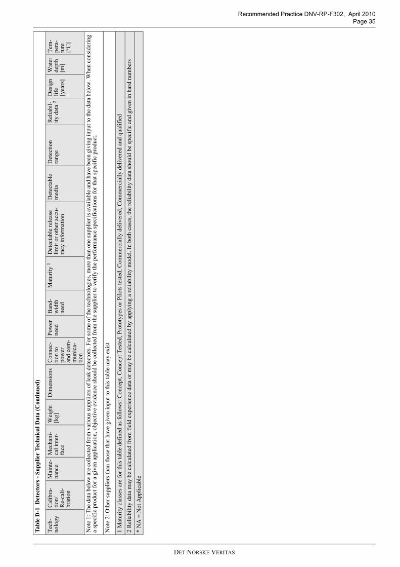
Recommended Practice DNV-RP-F302, April 2010Page 35
Note
1: T
he d
ata
belo
w a
re c
olle
cted
from
var
ious
supp
liers
of l
eak
dete
ctor
s. Fo
r som
e of
the
tech
nolo
gies
, mor
e th
an o
ne su
pplie
r is a
vaila
ble
and
have
bee
n gi
ving
inpu
t to
the
data
bel
ow. W
hen
cons
ider
ing
a sp
ecifi
c pr
oduc
t for
a g
iven
app
licat
ion,
obj
ectiv
e ev
iden
ce sh
ould
be
colle
cted
from
the
supp
lier t
o ve
rify
the
perf
orm
ance
spec
ifica
tions
for t
hat s
peci
fic p
rodu
ct.
Not
e 2:
Oth
er su
pplie
rs th
an th
ose
that
hav
e gi
ven
inpu
t to
this
tabl
e m
ay e
xist
1 M
atur
ity c
lass
es a
re fo
r thi
s tab
le d
efin
ed a
s fol
low
s: C
once
pt, C
once
pt T
este
d, P
roto
type
s or P
ilots
test
ed, C
omm
erci
ally
del
iver
ed, C
omm
erci
ally
del
iver
ed a
nd q
ualif
ied
2 R
elia
bilit
y da
ta m
ay b
e ca
lcul
ated
from
fiel
d ex
perie
nce
data
or m
ay b
e ca
lcul
ated
by
appl
ying
a re
liabi
lity
mod
el. I
n bo
th c
ases
, the
relia
bilit
y da
ta sh
ould
be
spec
ific
and
give
n in
har
d nu
mbe
rs
* N
A =
Not
App
licab
le
Tabl
e D
-1 D
etec
tors
- Su
pplie
r Te
chni
cal D
ata
(Con
tinue
d)
Tech
-no
logy
Cal
ibra
-tio
n/R
e-ca
li-br
atio
n
Mai
nte-
nanc
eM
echa
ni-
cal i
nter
-fa
ce
Wei
ght
[kg]
Dim
ensi
ons
Con
nec-
tion
to
pow
er
and
com
-m
unic
a-tio
n
Pow
er
need
Ban
d-w
idth
ne
ed
Mat
urity
1D
etec
tabl
e re
leas
e lim
it or
oth
er a
ccu-
racy
info
rmat
ion
Det
ecta
ble
med
iaD
etec
tion
rang
eR
elia
bil-
ity d
ata
2D
esig
n lif
e [y
ears
]
Wat
er
dept
h [m
]
Tem
-pe
ra-
ture
[°
C]
DET NORSKE VERITAS

Recommended Practice DNV-RP-F302, April 2010 Page 36
DET NORSKE VERITAS