DNV-OS-C301: Stability and Watertight Integrity
34
OFFSHORE STANDARD DET NORSKE VERITAS DNV-OS-C301 STABILITY AND WATERTIGHT INTEGRITY APRIL 2011
Transcript of DNV-OS-C301: Stability and Watertight Integrity

OFFSHORE STANDARD
DNV-OS-C301STABILITY AND WATERTIGHT INTEGRITY
APRIL 2011
DET NORSKE VERITAS
FOREWORDDET NORSKE VERITAS (DNV) is an autonomous and independent foundation with the objectives of safeguarding life,property and the environment, at sea and onshore. DNV undertakes classification, certification, and other verification andconsultancy services relating to quality of ships, offshore units and installations, and onshore industries worldwide, andcarries out research in relation to these functions.
DNV service documents consist of amongst other the following types of documents:— Service Specifications. Procedual requirements.— Standards. Technical requirements.— Recommended Practices. Guidance.
The Standards and Recommended Practices are offered within the following areas:A) Qualification, Quality and Safety MethodologyB) Materials TechnologyC) StructuresD) SystemsE) Special FacilitiesF) Pipelines and RisersG) Asset OperationH) Marine OperationsJ) Cleaner EnergyO) Subsea Systems
The electronic pdf version of this document found through http://www.dnv.com is the officially binding version© Det Norske Veritas
Any comments may be sent by e-mail to [email protected] subscription orders or information about subscription terms, please use [email protected] Typesetting (Adobe Frame Maker) by Det Norske Veritas
This service document has been prepared based on available knowledge, technology and/or information at the time of issuance of this document, and is believed to reflect the best ofcontemporary technology. The use of this document by others than DNV is at the user's sole risk. DNV does not accept any liability or responsibility for loss or damages resulting fromany use of this document.

Offshore Standard DNV-OS-C301, APRIL 2011Changes – Page 3
CHANGES• GeneralThis document supersedes DNV-OS-C301, October 2010.
Main changes in April 2011:— The standard has been altered (mainly Ch.2 Sec.2) to align with the requirements in DNV's “Classification
Rules for Ships” book.— Material requirements to water- and weathertight doors and hatches have been added to Ch.2. Sec.2.— The requirements related to drainage arrangement in order to prevent corrosion have been added.— Mandatory requirements to check buckling of weathertight closing appliances have been added to Ch.2
Sec.2.— A number of clarifications have been added to test requirements of water- and weathertight closing
appliances (Ch.2 Sec.2 I).— Ch.3 Sec.1 has been updated. A number of components have been set as mandatory for certification.
DET NORSKE VERITAS
Offshore Standard DNV-OS-C301, APRIL 2011 Page 4 – Contents
CONTENTS
CH. 1 INTRODUCTION.............................................................................................................................. 6
Sec. 1 Introduction ........................................................................................................................................ 7
A. General ............................................................................................................................................................................ 7A 100 Introduction........................................................................................................................................................... 7A 200 Objectives ............................................................................................................................................................. 7
B. Normative References..................................................................................................................................................... 7B 100 General.................................................................................................................................................................. 7B 200 Reference documents ............................................................................................................................................ 7
C. Informative References ................................................................................................................................................... 8C 100 General.................................................................................................................................................................. 8
D. Definitions ...................................................................................................................................................................... 8D 100 Verbal forms ......................................................................................................................................................... 8D 200 Definitions ............................................................................................................................................................ 8D 300 Abbreviations and symbols................................................................................................................................. 10
E. Documentation .............................................................................................................................................................. 10E 100 General................................................................................................................................................................ 10
CH. 2 TECHNICAL PROVISIONS.......................................................................................................... 11
Sec. 1 Stability ............................................................................................................................................. 12
A. General .......................................................................................................................................................................... 12A 100 Scope................................................................................................................................................................... 12
B. Determination of Wind Forces...................................................................................................................................... 12B 100 Heeling moment curves ...................................................................................................................................... 12
C. Determination of Lightweight....................................................................................................................................... 13C 100 Inclining test ....................................................................................................................................................... 13
D. Intact Stability Requirements........................................................................................................................................ 14D 100 General................................................................................................................................................................ 14D 200 Ship shaped units or installations........................................................................................................................ 14D 300 Column stabilised units....................................................................................................................................... 15D 400 Self elevating units or installations ..................................................................................................................... 15D 500 Deep draught floating installations ..................................................................................................................... 15
E. Damage Stability Requirements.................................................................................................................................... 15E 100 General................................................................................................................................................................ 15E 200 Ship shaped units or installations........................................................................................................................ 15E 300 Self elevating units or installations ..................................................................................................................... 16E 400 Column stabilised units or installations .............................................................................................................. 16E 500 Deep draught floating installations ..................................................................................................................... 17E 600 Extent of damage – ship shaped and self elevating units or installations........................................................... 17E 700 Extent of damage – column stabilised units and deep draught floating installations ......................................... 18E 800 Chain lockers ...................................................................................................................................................... 18E 900 Load line and draught marks............................................................................................................................... 18E 1000 Extent of watertight and weathertight closing of external openings................................................................... 18E 1100 Internal watertight integrity and subdivision ...................................................................................................... 18E 1200 Loading computers ............................................................................................................................................. 18
Sec. 2 Watertight Integrity, Freeboard and Weathertight Closing Appliances.................................... 19
A. General .......................................................................................................................................................................... 19A 100 Application.......................................................................................................................................................... 19
B. Materials........................................................................................................................................................................ 19B 100 Technical requirements....................................................................................................................................... 19B 200 Supplementary classification requirements ........................................................................................................ 19
C. Watertight Integrity....................................................................................................................................................... 19C 100 General................................................................................................................................................................ 19C 200 Internal openings................................................................................................................................................. 19C 300 External openings ............................................................................................................................................... 20C 400 Strength of watertight doors and hatch covers.................................................................................................... 20
DET NORSKE VERITAS
Offshore Standard DNV-OS-C301, APRIL 2011 Contents – Page 5
C 500 Frame and bulkhead interface............................................................................................................................. 22C 600 Operation and control of watertight doors and hatch covers .............................................................................. 22
D. Weathertight Closing Appliances ................................................................................................................................. 23D 100 General................................................................................................................................................................ 23D 200 Weathertight doors.............................................................................................................................................. 23D 300 Weathertight hatch coamings and covers ........................................................................................................... 24D 400 Gaskets and closing devices................................................................................................................................ 24D 500 Drainage arrangement......................................................................................................................................... 25D 600 Buckling check ................................................................................................................................................... 25
E. Freeboard ...................................................................................................................................................................... 26E 100 General................................................................................................................................................................ 26E 200 Self elevating units or installations ..................................................................................................................... 26E 300 Column stabilised units or installations .............................................................................................................. 26
F. Ventilators and Air Pipes .............................................................................................................................................. 26F 100 General................................................................................................................................................................ 26
G. Inlets, Discharges and Scuppers.................................................................................................................................... 27G 100 Sea inlets and discharges in closed systems ....................................................................................................... 27G 200 Discharges........................................................................................................................................................... 27G 300 Scuppers.............................................................................................................................................................. 28
H. Side Scuttles and Windows........................................................................................................................................... 28H 100 General................................................................................................................................................................ 28
I. Testing of Doors and Hatch Covers .............................................................................................................................. 28I 100 Pressure testing of watertight doors and hatch covers ........................................................................................ 28I 200 Hose testing of watertight and weathertight doors and hatch covers.................................................................. 29I 300 Function testing of watertight doors and hatch covers ....................................................................................... 29
J. Closing Arrangements for Doors and Hatch Covers .................................................................................................... 29J 100 Description of waterlines (beach lines)............................................................................................................... 29J 200 Description of location of openings.................................................................................................................... 29J 300 Operation and locking......................................................................................................................................... 30
CH. 3 CERTIFICATION AND CLASSIFICATION .............................................................................. 32
Sec. 1 General .............................................................................................................................................. 33
A. Introduction ................................................................................................................................................................... 33A 100 Application.......................................................................................................................................................... 33
B. Design Review .............................................................................................................................................................. 33B 100 Documentation requirements .............................................................................................................................. 33B 200 Specific classification requirements ................................................................................................................... 33
C. Certification of Materials and Components .................................................................................................................. 33C 100 General................................................................................................................................................................ 33C 200 Certification requirements under DNV-OS-C301 .............................................................................................. 34
DET NORSKE VERITAS
OFFSHORE STANDARDDNV-OS-C301
STABILITY AND WATERTIGHT INTEGRITY
CHAPTER 1
INTRODUCTION
CONTENTS PAGE
Sec. 1 Introduction.......................................................................................................................... 7
DET NORSKE VERITASVeritasveien 1, NO-1322 Høvik, Norway Tel.: +47 67 57 99 00 Fax: +47 67 57 99 11

Offshore Standard DNV-OS-C301, April 2011 Page 7 – Ch.1 Sec.1
SECTION 1INTRODUCTION
A. General
A 100 Introduction101 This offshore standard provides principles, technical requirements and guidance related to stability,watertight integrity, freeboard and weathertight closing appliances for mobile offshore units and floatingoffshore installations. The types of units and installations that are covered by this standard include:
— ship shaped units— column stabilised units— self elevating units— deep draught units.
Guidance note:For novel designs, not recognised by the typical features of a known type of design, the stability requirements haveto be considered separately and based on an evaluation of risks reflecting the unit's design, the intended operationalaspects and the environmental conditions.
---e-n-d---of---G-u-i-d-a-n-c-e---n-o-t-e---
102 The standard has been written for general worldwide application. Governmental regulations may includerequirements in excess of the provisions by this standard depending on the size, type, location and intendedservice of the offshore unit or installation.
A 200 Objectives201 The objectives of this standard are to:
— provide an internationally acceptable standard of safety by defining minimum requirements for stability,watertight integrity, freeboard and weathertight closing appliances
— serve as a contractual reference document between suppliers and purchasers— serve as a guideline for designers, suppliers, purchasers and regulators— specify procedures and requirements for units or installations subject to DNV certification and
classification.
B. Normative References
B 100 General101 The standards given in 200 include provisions which, through reference in the text, constitute provisionsof this offshore standard. The latest issue of the references shall be used unless otherwise agreed.102 Other recognised standards may be used provided it can be demonstrated that these meet or exceed therequirements of the standards given in 200.103 Any deviations, exceptions and modifications to the design codes and standards shall be documented andagreed between the contractor, purchaser and verifier, as applicable.
B 200 Reference documents201 Applicable DNV documents are given in Table B1.
Table B1 DNV Rules, Standards and Recommended PracticesReference TitleDNV-OS-C201 Structural Design of Offshore Units (WSD method)DNV-OS-D101 Marine and Machinery Systems and Equipment
Rules for Classification of ShipsDNV-RP-A201 Plan Approval Documentation Types – Definitions
DET NORSKE VERITAS

Offshore Standard DNV-OS-C301, April 2011Ch.1 Sec.1 – Page 8
202 Other reference documents are given in Table B2.
C. Informative ReferencesC 100 General101 Informative references are not considered mandatory in the application of this offshore standard, but maybe applied or used for background information.102 Informative references are given in Table C1.
D. Definitions D 100 Verbal forms101 Shall: Indicates requirements strictly to be followed in order to conform to this standard and from whichno deviation is permitted.102 Should: Indicates that among several possibilities one is recommended as particularly suitable, withoutmentioning or excluding others, or that a certain course of action is preferred but not necessarily required. Otherpossibilities may be applied subject to agreement.103 May: Verbal form used to indicate a course of action permissible within the limits of the standard.
D 200 Definitions201 Column stabilised unit: A unit with the main deck connected to the underwater hull or footings bycolumns.202 Damage penetration zone: Defined as 1.5 m from the outer skin. The damage penetration zone is limitedto exposed portions only.203 Damage waterline: The final equilibrium waterline, including the wind heeling moment, after a damage.204 Downflooding: Any flooding of the interior of any part of the buoyant structure of a unit throughopenings which cannot be closed watertight, as appropriate, in order to meet the intact or damage stabilitycriteria, or which are required for operational reason to be left open.205 Dynamic angle: The angle of heel where the area requirement according to the stability requirements ofCh.2 Sec.1 is achieved.206 Exposed portions: Those portions of the structure that are exposed to collision from other units.
Guidance note:For a column stabilised unit, the exposed portions are the portions of the columns, pontoons and bracings which arelocated outboard of a line drawn through the centres of the periphery columns, see Fig. 1.
Table B2 Normative referencesReference TitleICLL 1966 International Convention on Load Lines, 1966, amended by Protocol 1988IMO MODU Code, 2009 Code for the Construction and Equipment of Mobile Offshore Drilling Units, 2009
Table C1 Informative referencesReference TitleISO 1751 Shipbuilding and marine structures - Ships’ side scuttlesISO 3903 Shipbuilding and marine structures - Ships’ ordinary rectangular windowsISO 1095 Shipbuilding and marine structures - Toughened safety glass panes for side scuttlesISO 614 Shipbuilding and marine structures - Toughened safety glass panes for rectangular
windows and side scuttles - Punch method of non-destructive testingSOLAS 1974 The International Convention for the Safety of Life at Sea, 1974, as amended
DET NORSKE VERITAS

Offshore Standard DNV-OS-C301, April 2011 Page 9 – Ch.1 Sec.1
Figure 1 Exposed portions of a column stabilised unit
---e-n-d---of---G-u-i-d-a-n-c-e---n-o-t-e---
207 Field move: The transit voyage which can be completed within 12 hours (transit time) or within the limitsof favourable reliable weather forecasts, whichever is less. However, for certain operating areas and seasons,a field move may exceed 12 hours if justified by independent reliable evidence.
Guidance note:Weather may be considered favourable up to Beaufort condition 6, i.e. average wind speed of 24 knots.
---e-n-d---of---G-u-i-d-a-n-c-e---n-o-t-e---
208 First intercept: The angle of heel where the righting moment curve intercepts the heeling moment curvefor the first time. The first intercept is also known as the static angle of heel.209 Floating offshore installation: A buoyant construction engaged in offshore operations including drilling,production, storage or support functions, and which is designed and built for installation at a particular offshorelocation.210 Freeboard: The distance measured vertically downwards amidship from the upper edge of the deck lineto the upper edge in the related load line.211 Lightweight: The unvariable weight of the unit; i.e. the basis for calculating the loading conditions.Anchors and cables are to be excluded from the lightweight and included in the loading conditions as variableloads.212 Maximum allowable vertical centre of gravity: The maximum vertical centre of gravity (VCG) whichcomplies with both intact and damage stability requirements at a given draught and service mode. All loadingconditions are to have a VCG below the maximum allowable value for the given draught and service mode.The free surface effect of each slack tank should be calculated about the axis at which the moment of inertia isthe greatest.213 Mobile offshore unit: A buoyant construction engaged in offshore operations including drilling,production, storage or support functions, not intended for service at one particular offshore site and which canbe relocated without major dismantling or modification.214 Offshore installation: A collective term to cover any construction, buoyant or non-buoyant, designed andbuilt for installation at a particular offshore location.215 Position 1 and 2: In accordance with Regulation 13 of the International Convention on Load Line 1966(ILLC 1966), adapted to mobile offshore units.216 Safe draught: A draught which can be accepted under loading condition corresponding to damagedcondition with respect to strength, and the requirement for minimum airgap is fulfilled.217 Second intercept: The angle of heel where the righting moment curve intercepts the heeling momentcurve for the second time.218 Self elevating unit: A unit with movable legs capable of raising its hull above the surface of the sea.219 Service modes:
— operation condition, i.e. normal working condition— temporary conditions, i.e. transient conditions during change of draught to reach another service mode or
installation mode
DET NORSKE VERITAS
Offshore Standard DNV-OS-C301, April 2011Ch.1 Sec.1 – Page 10
— survival condition, i.e. in case of severe storms— transit condition.
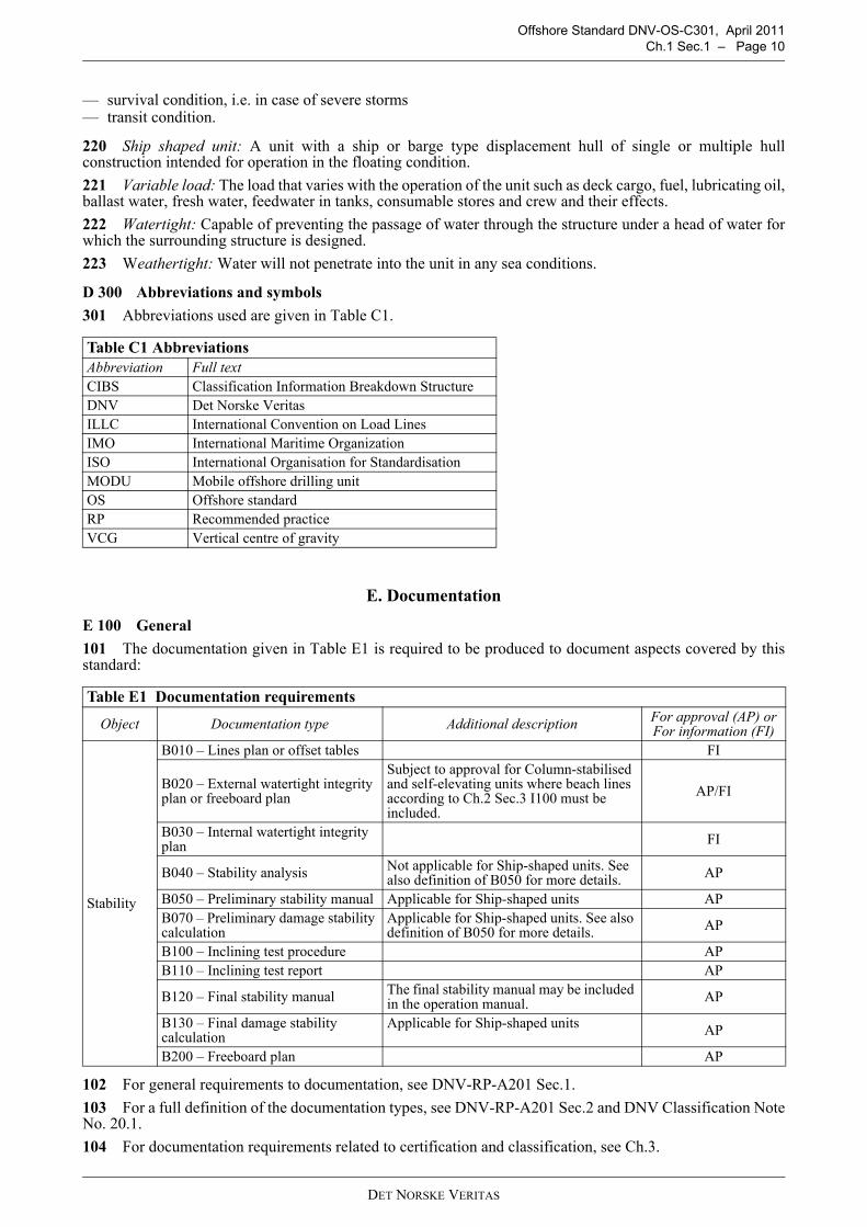
220 Ship shaped unit: A unit with a ship or barge type displacement hull of single or multiple hullconstruction intended for operation in the floating condition.221 Variable load: The load that varies with the operation of the unit such as deck cargo, fuel, lubricating oil,ballast water, fresh water, feedwater in tanks, consumable stores and crew and their effects.222 Watertight: Capable of preventing the passage of water through the structure under a head of water forwhich the surrounding structure is designed.223 Weathertight: Water will not penetrate into the unit in any sea conditions.
D 300 Abbreviations and symbols301 Abbreviations used are given in Table C1.
E. Documentation
E 100 General101 The documentation given in Table E1 is required to be produced to document aspects covered by thisstandard:
102 For general requirements to documentation, see DNV-RP-A201 Sec.1. 103 For a full definition of the documentation types, see DNV-RP-A201 Sec.2 and DNV Classification NoteNo. 20.1.104 For documentation requirements related to certification and classification, see Ch.3.
Table C1 AbbreviationsAbbreviation Full textCIBS Classification Information Breakdown StructureDNV Det Norske VeritasILLC International Convention on Load LinesIMO International Maritime OrganizationISO International Organisation for StandardisationMODU Mobile offshore drilling unitOS Offshore standardRP Recommended practiceVCG Vertical centre of gravity
Table E1 Documentation requirements
Object Documentation type Additional description For approval (AP) or For information (FI)
Stability
B010 – Lines plan or offset tables FI
B020 – External watertight integrity plan or freeboard plan
Subject to approval for Column-stabilised and self-elevating units where beach lines according to Ch.2 Sec.3 I100 must be included.
AP/FI
B030 – Internal watertight integrity plan FI
B040 – Stability analysis Not applicable for Ship-shaped units. See also definition of B050 for more details. AP
B050 – Preliminary stability manual Applicable for Ship-shaped units APB070 – Preliminary damage stability calculation
Applicable for Ship-shaped units. See also definition of B050 for more details. AP
B100 – Inclining test procedure APB110 – Inclining test report AP
B120 – Final stability manual The final stability manual may be included in the operation manual. AP
B130 – Final damage stability calculation
Applicable for Ship-shaped units AP
B200 – Freeboard plan AP
DET NORSKE VERITAS

OFFSHORE STANDARDDNV-OS-C301
STABILITY AND WATERTIGHT INTEGRITY
CHAPTER 2
TECHNICAL PROVISIONS
CONTENTS PAGE
Sec. 1 Stability .............................................................................................................................. 12Sec. 2 Watertight Integrity, Freeboard and Weathertight Closing Appliances ............................ 19
DET NORSKE VERITASVeritasveien 1, NO-1322 Høvik, Norway Tel.: +47 67 57 99 00 Fax: +47 67 57 99 11
Offshore Standard DNV-OS-C301, April 2011 Page 12 – Ch.2 Sec.1
SECTION 1STABILITY
A. GeneralA 100 Scope101 This section gives requirements related to the following design parameters of mobile offshore units andfloating offshore installations:
1) Buoyancy and floatability.2) Wind exposed portions.3) Draught range at various modes of service.4) Watertight and weathertight closing of external openings.5) Internal watertight integrity and watertight subdivision.6) Lightweight and loading conditions.
102 The combination of the design parameters under 101 (1-5) will determine the maximum allowablevertical centre of gravity (VCG) of the unit or installation at the applicable service draughts and modes.103 The loading of the unit or installation at various service draughts and modes shall be within the limits ofmaximum allowable VCG-curves. 104 In order to determine VCG of the actual loading conditions, the lightweight and its centre of gravity mustbe known. This shall be obtained by an inclining test carried out in accordance with C.105 The requirements of this section are based on the IMO MODU Code, 2009. Text which has been takendirectly from the code is written in italics.106 Deep draught floating installations (e.g. SPARs) are not directly covered by the IMO MODU Code.Criteria identical to those of a column stabilised unit or installations have been adopted.
B. Determination of Wind ForcesB 100 Heeling moment curves101 The curves of wind heeling moments should be drawn for wind forces calculated by the following formula:
102 Wind forces shall be considered from any direction relative to the unit and the value of the wind velocityshall be as follows:
— in general a minimum wind velocity of 36 m/s (70 knots) for offshore service shall be used for normaloperating conditions and a minimum wind velocity of 51.5 m/s (100 knots) shall be used for the severestorm conditions
— where a unit is to be limited in operation to sheltered locations (protected inland waters such as lakes, bays,swamps, rivers, etc.) consideration shall be given to a reduced wind velocity of not less than 25.8 m/s (50knots) for normal operating conditions.
103 In calculating the projected areas to the vertical plane, the area of surfaces exposed to wind due to heelor trim, such as under-deck surfaces, etc., shall be included using the appropriate shape factor. Open trusswork may be approximated by taking 30% of the projected block area of both the front and back section, i.e.60% of the projected area of one side.104 In calculating the wind heeling moments, the lever of the wind overturning force shall be taken vertically
F = the wind force (Newton)Cs = the shape coefficient depending on the shape of the structural member exposed to the wind (see
Table B1)Ch = the height coefficient depending on the height above sea level of the structural member exposed to
wind (see Table B2)P = the air mass density (1.222 kg/m3)V = the wind velocity (metres per second)A = the projected area of all exposed surfaces in either the upright or the heeled condition (square
metres)
F 0,5 Cs Ch P V2 A⋅ ⋅ ⋅ ⋅=
DET NORSKE VERITAS

Offshore Standard DNV-OS-C301, April 2011Ch.2 Sec.1 – Page 13
from the centre of pressure of all surfaces exposed to the wind to the centre of lateral resistance of theunderwater body of the unit. The unit is to be assumed floating free of mooring restraint.105 For units supported by dynamic positioning systems, the centre of the thruster force shall be applied asthe centre of lateral resistance.
Guidance note:In case the total maximum thruster force is less than the wind force, the total wind heeling moment may be taken asa combination of wind moment and thruster moment. The lever of the wind force shall in this case be taken to thecentre of the lateral resistance of the hull. The lever of the maximum thruster force is taken vertically from centre ofthe thruster force to the centre of the lateral resistance of the underwater hull.
106 The wind heeling moment curve shall be calculated for a sufficient number of heel angles to define thecurve. For ship-shaped hulls the curve may be assumed to vary as the cosine function of vessel heel.107 Wind heeling moments derived from wind tunnel tests on a representative model of the unit may beconsidered as alternatives to the methods given in 101.
C. Determination of Lightweight
C 100 Inclining test101 An inclining test shall be required for the first unit of a design, when the unit is as near to completion aspossible, to determine accurately the light ship data (weight and position of centre of gravity).102 For successive units which are identical by design, the light ship data of the first unit of the series maybe accepted in lieu of an inclining test, provided the difference in light ship displacement or position of centreof gravity due to weight changes for minor differences in machinery, outfitting or equipment, confirmed by the
Table B1 Values of the coefficient CsShape CsSpherical 0.4Cylindrical 0.5Large flat surface (hull, deckhouse, smooth under-deck areas) 1.0Drilling derrick 1.25Wires 1.2Exposed beams and girders under deck 1.3Small parts 1.4Isolated shapes (crane, beam, etc.) 1.5Clustered deckhouses or similar structures 1.1
Table B2 Values of the coefficient ChHeight above sea level (metres) Ch0 – 15.3 1.0015.3 – 30.5 1.1030.5 – 46.0 1.2046.0 – 61.0 1.3061.0 – 76.0 1.3776.0 – 91.5 1.4391.5 – 106.5 1.48106.5 – 122.0 1.52122.0 – 137.0 1.56137.0 – 152.5 1.60152.5 – 167.5 1.63167.5 – 183.0 1.67183.0 – 198.0 1.70198.0 – 213.5 1.72213.5 – 228.5 1.75228.5 – 244.0 1.77244.0 – 256.0 1.79Above 256 1.80
DET NORSKE VERITAS
Offshore Standard DNV-OS-C301, April 2011 Page 14 – Ch.2 Sec.1
results of a deadweight survey, are less than 1% of the values of the light ship displacement and principalhorizontal dimensions as determined for the first series.
Such dispensation cannot be granted for column stabilised units.
D. Intact Stability Requirements
D 100 General101 Each unit shall be capable of attaining a severe storm condition in a period of time consistent with themeteorological conditions. The procedures recommended and the approximate length of time required,considering both operating conditions and transit conditions, shall be contained in the stability manual. It shallbe possible to achieve the severe storm condition without the removal or relocation of solid consumables orother variable load. However, it may be acceptable loading a unit past the point at which solid consumableswould have to be removed or relocated to go to severe storm condition under the following conditions, providedthe allowable VCG requirement is not exceeded:
1) In a geographic location where weather conditions annually or seasonally do not become sufficientlysevere to require a unit to go to severe storm condition, or
2) Where a unit is required to support extra deck load for a short period of time that falls well within a periodfor which the weather forecast is favourable.
The geographic locations, weather conditions and loading conditions in which this is permitted shall beidentified in the stability manual.
102 Alternative stability criteria may be acceptable, provided an equivalent level of safety is maintained andif it can demonstrate to afford adequate positive initial stability. In determining the acceptability of such criteria,the following will be considered and taken into account as appropriate:
1) Environmental conditions representing realistic winds (including gusts) and waves appropriate for world-wide service in various modes of operation;
2) Dynamic response of a unit. Analysis should include the results of wind tunnel tests, wave tank model tests,and non-linear simulation, where appropriate. Any wind and wave spectra used shall cover sufficientfrequency ranges to ensure that critical motion responses are obtained;
3) Potential for flooding taking into account dynamic responses in a seaway;4) Susceptibility to capsizing considering the unit's restoration energy and the static inclination due to the
mean wind speed and the maximum dynamic response;5) An adequate safety margin to account for uncertainties.
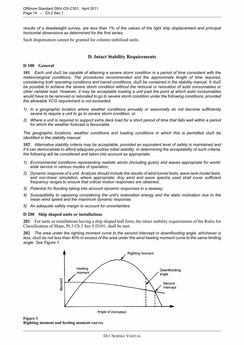
D 200 Ship shaped units or installations201 For units or installations having a ship shaped hull form, the intact stability requirements of the Rules forClassification of Ships, Pt.3 Ch.3 Sec.9 D101, shall be met.202 The area under the righting moment curve to the second intercept or downflooding angle, whichever isless, shall be not less than 40% in excess of the area under the wind heeling moment curve to the same limitingangle. See Figure 1.
Figure 1 Righting moment and heeling moment curves
DET NORSKE VERITAS

Offshore Standard DNV-OS-C301, April 2011Ch.2 Sec.1 – Page 15
D 300 Column stabilised units301 The area under the righting moment curve to the angle of downflooding shall be not less than 30% inexcess of the area under the wind heeling moment curve to the same limiting angle.302 The righting moment curve shall be positive over the entire range of angles from upright to the secondintercept.
D 400 Self elevating units or installations401 The area under the righting moment curve to the second intercept or downflooding angle, whichever isless, shall be not less than 40% in excess of the area under the wind heeling moment curve to the same limitingangle.402 The righting moment curve shall be positive over the entire range of angles from upright to the secondintercept.
D 500 Deep draught floating installations501 The area under the righting moment curve to the second intercept or downflooding angle, whichever isless, shall be not less than 30% in excess of the area under the wind heeling moment curve to the same limitingangle.502 The righting moment curve shall be positive over the entire range of angles from upright to the secondintercept.
E. Damage Stability RequirementsE 100 General101 It shall be demonstrated that the unit or installation complies with the requirements of 200 to 500 bycalculations, which take into consideration the proportions and design characteristics of the unit or installationand the arrangements and configuration of the damaged compartments. In making these calculations it shallbe assumed that the unit or installation is in the worst anticipated service condition as regards stability and isfloating free of mooring restraints.102 The ability to reduce angles of inclination by pumping out or ballasting compartments or application ofmooring forces, etc., shall not be considered as justifying any relaxation of the requirements.103 The following permeability factors shall be assumed in the calculations:
Store rooms: 0.60Engine room: 0.85Tanks, void spaces etc: 0.95
Other permeabilities may be accepted if documented by calculations.104 Alternative subdivision and damage stability criteria may be acceptable provided an equivalent level ofsafety is maintained. The alternative stability criteria, should consider at least the following and take intoaccount:
1) Extent of damage as set out in 600 and 700;2) On column stabilised units, the flooding of any compartment as set out in 402;3) The provision of an adequate margin against capsizing.
E 200 Ship shaped units or installations201 The unit shall have sufficient freeboard and be subdivided by means of watertight decks and bulkheadsto provide sufficient buoyancy and stability to withstand in general the flooding of any one compartment in anyoperating or transit condition consistent with the damage assumptions set out in 600.202 The unit should have sufficient reserve stability in a damaged condition to withstand the wind heelingmoment based on a wind velocity of 25.8 m/s (50 knots) superimposed from any direction. In this condition thefinal waterline, after flooding, should be below the lower edge of any downflooding opening.
DET NORSKE VERITAS

Offshore Standard DNV-OS-C301, April 2011 Page 16 – Ch.2 Sec.1
E 300 Self elevating units or installations
Figure 2 Residual Stability for self-elevating units
301 The unit shall have sufficient freeboard and be subdivided by means of watertight decks and bulkheadsto provide sufficient buoyancy and stability to withstand:
1) in general the flooding of any compartment in any operating or transit condition consistent with the damageassumptions set out in 600; and
2) flooding of any single compartment while meeting the following criterion (see figure 2)
RoS ≥ 7°+(1.5θS), (but at least 10°)where:RoS ≥ 10°
RoS = range of stability, in degrees = θm – θswhere:θm = maximum angle of positive stability, in degreesθs = static angle of inclination after damage, in degrees
The range of stability is determined without reference to the angle of downflooding.302 The unit shall have sufficient reserve stability in a damaged condition to withstand the wind heelingmoment based on a wind velocity of 25.8 m/s (50 knots) superimposed from any direction. In this condition thefinal waterline, after flooding, should be below the lower edge of any downflooding opening.
E 400 Column stabilised units or installations401 The unit shall have sufficient freeboard and be subdivided by means of watertight decks and bulkheadsto provide sufficient buoyancy and stability to withstand a wind heeling moment induced by a wind velocity of25.8 m/s (50 knots) superimposed from any direction in any operating or transit condition, taking the followingconsiderations into account:
1) The angle of inclination after the damage set out in 700 shall not be greater than 17°;2) Any opening (through which progressive flooding may occur) below the final waterline shall be made
watertight, and openings within 4 m above the final waterline shall be made weathertight;3) The righting moment curve, after the damage set out above, shall have, from the first intercept to the lesser
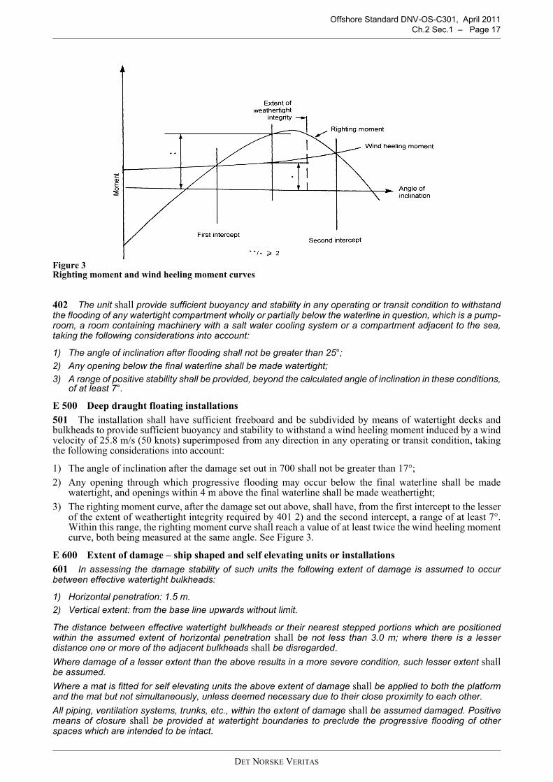
of the extent of weathertight integrity required by 401 2) and the second intercept, a range of at least 7°.Within this range, the righting moment curve shall reach a value of at least twice the wind heeling momentcurve, both being measured at the same angle. See Figure 3.
DET NORSKE VERITAS
Offshore Standard DNV-OS-C301, April 2011Ch.2 Sec.1 – Page 17
Figure 3 Righting moment and wind heeling moment curves
402 The unit shall provide sufficient buoyancy and stability in any operating or transit condition to withstandthe flooding of any watertight compartment wholly or partially below the waterline in question, which is a pump-room, a room containing machinery with a salt water cooling system or a compartment adjacent to the sea,taking the following considerations into account:
1) The angle of inclination after flooding shall not be greater than 25°;2) Any opening below the final waterline shall be made watertight;3) A range of positive stability shall be provided, beyond the calculated angle of inclination in these conditions,
of at least 7°.
E 500 Deep draught floating installations501 The installation shall have sufficient freeboard and be subdivided by means of watertight decks andbulkheads to provide sufficient buoyancy and stability to withstand a wind heeling moment induced by a windvelocity of 25.8 m/s (50 knots) superimposed from any direction in any operating or transit condition, takingthe following considerations into account:
1) The angle of inclination after the damage set out in 700 shall not be greater than 17°;2) Any opening through which progressive flooding may occur below the final waterline shall be made
watertight, and openings within 4 m above the final waterline shall be made weathertight;3) The righting moment curve, after the damage set out above, shall have, from the first intercept to the lesser
of the extent of weathertight integrity required by 401 2) and the second intercept, a range of at least 7°.Within this range, the righting moment curve shall reach a value of at least twice the wind heeling momentcurve, both being measured at the same angle. See Figure 3.
E 600 Extent of damage – ship shaped and self elevating units or installations601 In assessing the damage stability of such units the following extent of damage is assumed to occurbetween effective watertight bulkheads:
1) Horizontal penetration: 1.5 m. 2) Vertical extent: from the base line upwards without limit.
The distance between effective watertight bulkheads or their nearest stepped portions which are positionedwithin the assumed extent of horizontal penetration shall be not less than 3.0 m; where there is a lesserdistance one or more of the adjacent bulkheads shall be disregarded.Where damage of a lesser extent than the above results in a more severe condition, such lesser extent shallbe assumed.Where a mat is fitted for self elevating units the above extent of damage shall be applied to both the platformand the mat but not simultaneously, unless deemed necessary due to their close proximity to each other.All piping, ventilation systems, trunks, etc., within the extent of damage shall be assumed damaged. Positivemeans of closure shall be provided at watertight boundaries to preclude the progressive flooding of otherspaces which are intended to be intact.
DET NORSKE VERITAS

Offshore Standard DNV-OS-C301, April 2011 Page 18 – Ch.2 Sec.1
E 700 Extent of damage – column stabilised units and deep draught floating installations701 In assessing the damage stability of such units, the following extent of damage shall be assumed:
1) Only those columns, underwater hulls and braces on the periphery of the unit shall be assumed to be damaged,and the damage shall be assumed in the exposed portions of the columns, underwater hulls and braces.
2) Columns and braces shall be assumed flooded by damage having a vertical extent of 3.0 m occurring at anylevel between 5.0 m above and 3.0 m below the draughts specified in the stability manual. Where a watertightflat is located within this region, the damage shall be assumed to have occurred in both compartments aboveand below the watertight flat in question. Lesser distances above or below the draughts may be applied uponconsideration, taking into account the actual operating conditions. However, the required damage region shallextend at least 1.5 m above and below the draught specified in the operating manual.
3) No vertical bulkhead shall be assumed damaged, except where bulkheads are spaced closer than adistance of one eighth of the column perimeter at the draught under consideration, measured at theperiphery, in which case one or more of the bulkheads shall be disregarded.
4) Horizontal penetration of damage shall be assumed to be 1.5 m.5) Underwater hull or footings shall be assumed damaged when operating in a transit condition in the same
manner as indicated in 1), 2), 4) and either 3) or 6), having regard to their shape.6) All piping, ventilation systems, trunks, etc., within the extent of damage shall be assumed damaged.
Positive means of closure shall be provided at watertight boundaries to preclude the progressive floodingof other spaces that are intended to be intact.
E 800 Chain lockers801 Chain lockers, which are not provided with weathertight closing appliances, shall be provided with levelalarm or sounding and bilge arrangement or drainage system in accordance with DNV-OS-D101. In this casethe chain pipes will be regarded as downflooding points.802 When chain lockers without weathertight closing appliances are used as ballast tanks, downfloodingthrough chain pipes can be disregarded at a given draught provided that chain lockers are:
— equipped as ballast tanks according to DNV-OS-D101— kept full at the given draught. This shall be stated in the stability manual.
Conditions during the cleaning of chain lockers shall be considered as temporary conditions.
E 900 Load line and draught marks901 The unit or installation shall have load line marks according to the maximum permissible draught in theafloat condition.902 The load line marks will be assigned on the basis of compliance with the requirements of this section aswell as other applicable requirements.903 Draught marks shall be located in positions, which will ensure accurate determination of draughts, trimand heel and where they are clearly visible to personnel operating the unit or installation. The reference lineshall be defined in the stability manual.
E 1000 Extent of watertight and weathertight closing of external openings1001 Watertight closing appliances are required for those external openings being submerged at least up toan angle of heel equal to the first intercept in intact or damage condition, whichever is greater.1002 Weathertight closing appliances are required for those external openings being submerged at least upto an angle of heel equal to the dynamic angle. This applies to any opening within 4.0 m above the finalwaterline as well.
E 1100 Internal watertight integrity and subdivision1101 The internal subdivision shall be adequate to enable the unit or installation to comply with the damagestability requirements of this section.1102 Ducts or piping, which may cause progressive flooding in case of damage, shall generally not be usedin the damage penetration zone.
E 1200 Loading computers1201 Loading computers for stability calculation shall be considered as supplementary to the stability manualor the stability part of the operation manual.
Guidance note:See DNV-OSS-101 Ch.2 Sec.1 F102 for information regarding approval of loading computers.
---e-n-d---of---G-u-i-d-a-n-c-e---n-o-t-e---
DET NORSKE VERITAS

Offshore Standard DNV-OS-C301, April 2011Ch.2 Sec.2 – Page 19
SECTION 2WATERTIGHT INTEGRITY, FREEBOARD AND WEATHERTIGHT
CLOSING APPLIANCES
A. General
A 100 Application101 This section provides requirements with regards to arrangement and design of watertight integrity andfreeboard for self elevating and column stabilised units and installations.102 Watertight integrity, freeboard plan and weathertight closing appliances for ship shaped units orinstallations shall comply with the Rules for Classification of Ships Pt.3 Ch.1, Ch.3 Sec.6 and Sec.9 with thefollowing additional requirements:
a) Doors in unprotected fronts and sides shall be of steel. b) For doors located in exposed positions in sides and front bulkheads, the requirements to sill heights apply
one deck higher than given by the Rules for Classification of Ships Pt.3 Ch.3 Sec.6 B.
103 Piping and electrical systems for operation of watertight closing appliances shall be in accordance withrelevant requirements given in DNV-OS-D101 unless otherwise specified in this section.
B. Materials
B 100 Technical requirements101 Materials for:
— rolled steel for structural applications and pressure vessels— steel tubes, pipes and fittings— steel forgings— steel castings— aluminium alloys
shall comply with the requirements given by DNV-OS-B101 unless otherwise stated in the relevant technicalreference documents.102 Stainless steel shall be with a maximum carbon content of 0.05%. The stainless steel material shall be ofthe white pickled and passivated condition.103 Aluminium shall be of seawater resistant type.
B 200 Supplementary classification requirements201 Certification requirements for materials are given in DNV-OS-B101, Ch.3.202 Rolled, forged or cast elements of steel and aluminium for structural application shall be supplied withDNV material certificates in compliance with the requirements given in DNV-OS-B101.
C. Watertight Integrity
C 100 General101 The number of openings in watertight subdivisions shall be kept to a minimum compatible with thedesign and proper working of the unit or installation. Where penetrations of watertight decks and bulkheads arenecessary for access, piping, ventilation, electrical cables etc., arrangements shall be made to maintain thewatertight integrity of the enclosed compartments.102 Locations of openings where watertight integrity is required, are illustrated in I.103 The strength and arrangement of sliding doors and hatch covers and their frames as well as the capacityof the closing systems shall be sufficient to ensure efficient closing of doors and hatch covers when water witha head of 2.0 m is flowing through the opening, and at an inclination of 17° in any direction.
C 200 Internal openings201 The means to ensure the watertight integrity of internal openings which are used during the operation ofthe unit or installation while afloat, shall comply with a) and b).
DET NORSKE VERITAS

Offshore Standard DNV-OS-C301, April 2011 Page 20 – Ch.2 Sec.2
a) Doors and hatch covers that are frequently used may normally be open if provided for remote closing froma central control room on a deck, which is above any final waterline after flooding and are also to beoperable locally from each side of the bulkhead. Indicators shall be provided at the control room showingwhether the doors or hatch covers are open or closed.
b) The requirements regarding remote control in a) may be dispensed with for those doors or hatch covers,which are normally closed, provided an alarm system (e.g. light signals) is arranged, showing personnel inthe control room whether the doors or hatch covers in question are open or closed. A notice shall be affixedto each such door or hatch cover to the effect that it is not to be left open.Guidance note:Frequently used door or hatch covers are those in major traffic and escape routes and doors likely to be used at least10 times a day.
---e-n-d---of---G-u-i-d-a-n-c-e---n-o-t-e---
202 To ensure the watertight integrity of internal openings which are kept permanently closed during theoperation of the unit or installation, a notice shall be affixed to each such closing appliance to the effect that itis to be kept closed. Manholes fitted with closely bolted covers need not be so marked.203 Where valves are provided at watertight boundaries to maintain watertight integrity, these valves shallbe capable of being operated from a control room. Valve position indicators shall be provided at the remotecontrol station.If the valves are remotely operated by means of mechanical devices, operation from a deck, which is above anyfinal waterline after flooding will be accepted. Valve position indicators shall be provided at the remote controlstation.
C 300 External openings301 Where watertight integrity is dependent on external openings, which are used during the operation of theunit or installation while afloat, they shall comply with a), b) and c).
a) The lower edge of openings of air pipes (regardless of their closing appliances) shall be above the damagewaterline.
b) The lower edge of ventilator openings, doors and hatch covers with manually operated means ofweathertight closures shall be above damage waterline, unless 303 applies.
c) Openings such as manholes fitted with closely bolted covers, and side scuttles or windows of the non-opening type with inside hinged deadlights may be submerged.
302 The requirements of 301 b) apply where the watertight integrity is dependent on external openings,which are permanently closed during the operation of the unit or installation, while afloat.303 External doors and hatch covers of limited size may be accepted between the damage waterline andfreeboard deck provided they are watertight closeable locally and by remote operation of the closing appliancesfrom the control room, with indicators showing whether the openings are closed or open.
C 400 Strength of watertight doors and hatch covers401 Watertight doors and hatch covers for internal and external openings shall be designed with a strengthequivalent to or better than required for the watertightness of the structure in which they are positioned.402 Strength of watertight doors and hatches in general shall comply with structural requirements stated inDNV-OS-C101 (LRFD) Sec. 5 or DNV-OS-C201 (WSD) Sec. 5 whichever is relevant.403 Provided flooding is a possible mode of failure based upon the damage assumptions as given in Sec.1,for compartments on both sides of a watertight door or hatch cover, the watertight door or hatch cover shall bedesigned to withstand the design pressure from both sides.404 The design pressure shall be taken as the waterhead corresponding to the vertical distance between theload point and the deepest waterline after damage.405 PlatingThe thickness of plating subjected to lateral pressure shall not be less than:
ka = correction factor for aspect ratio of plate field= (1.1 minus 0.25 s/l)2
ppf
da
kpsk
t⋅
⋅⋅⋅=
σ5.16 (mm)
DET NORSKE VERITAS

Offshore Standard DNV-OS-C301, April 2011Ch.2 Sec.2 – Page 21
Guidance note:The plating is normally assumed to be simply supported along the edges.
---e-n-d---of---G-u-i-d-a-n-c-e---n-o-t-e---
406 The thickness of plating is in no case to be less than the minimum bulkhead thickness.407 Stiffeners on doors and hatch coversThe section modulus of panel stiffeners shall not be less than:
The effective flange of the plate shall be included when calculating actual section modulus of the stiffeners.408 Minimum stiffness of door and hatch cover edge stiffenersEdge stiffeners of doors and hatch covers shall have a moment of inertia not less than:
The effective flange of the plate shall be included when calculating the actual moment of inertia of thestiffeners.409 Stiffness of door and hatch cover framesThe frames (coamings) shall have necessary stiffness to avoid large deflections resulting in leakage in thedamage condition.
= maximum 1.0 for s/l = 0.4= minimum 0.72 for s/l = 1.0
pd = design pressure in kN/m2 corresponding to the head of water to damage waterlinekpp = fixation parameter for plates
kpp = 1.0 for clamped edges= 0.5 for simply supported edges
σf = minimum yield strength in N/mm2
s = stiffener spacing in m, measured along the platingl = stiffener span in m, measured along the top flange of the member
l = stiffener span in m. For doors with stiffeners in one direction only l shall be taken as the span length between cleat support points in door
m = bending moment factorm = 8 if simply supported at both ends, or simply supported at one end and fixed at the other end
= 12 if fixed at both endsks is dependent on support condition:ks = 1.0 if at least one end is clamped
= 0.9 if both ends are simply supported.pd = design pressure (kN/mm2) as given in 405
pe = packing line pressure along edges in N/mm, minimum 5 N/mm= pd b, whichever is greater
pd = design pressure (kN/mm2) as given in 405b = load breadth, normally taken as h/3 or w/2, whichever is less, whereh and w are height and width of door or hatch in m.a = distance between closing devices in m, to be measured along door or hatch edges
62
10⋅=sf
d
kmsplZ
σ(mm3)
44108 apI e= (mm4)
DET NORSKE VERITAS

Offshore Standard DNV-OS-C301, April 2011 Page 22 – Ch.2 Sec.2
The frame shall be continuous on all four sides. The frame shall have a section moment of inertia on each sideof not less than:
410 Securing devices shall be designed for the load acting also on the opposite side of where they arepositioned. Allowable stresses in securing devices are as follows:
The conversion factor f1 shall be taken as:
σf= minimum yield strength in N/mm2
C 500 Frame and bulkhead interface501 Door or hatch frames shall be installed, as appropriate by either bolting through air tight isolationgaskets, or by a continuous fillet weld all around. Frames shall be reinforced at hinges, locks and closing devicepositions. Detailing shall minimise galvanic corrosion502 To reduce transmission of forces from bulkhead into the frame which may affect proper alignment andoperation of a door or hatch, maximum plate buckling at perimeter of cut-out shall be 5 mm along astraightedge. Alternatively the cut-out maybe terminated at a welded angle profile, into which the frame maybe welded or bolted.
Guidance note:For frames located in high-stress areas it is recommended to arrange cut-out with corner radius more than 50 mm inorder to reduce stress concentration and possible fatigue issues.
---e-n-d---of---G-u-i-d-a-n-c-e---n-o-t-e---
503 The door (hatch) frame shall have no groove at the bottom in which dirt might lodge and prevent the door(hatch) from closing properly.
Guidance note:The recess of the flush hatches located on main deck is prone to corrosion. Therefore, it is recommended that hatchcovers are supplied with an operation and maintenance manual including:
— opening and closing instructions— maintenance requirements for packing, securing devices and operating times— cleaning instructions for the drainage system— corrosion prevention instructions— list of spare parts.
---e-n-d---of---G-u-i-d-a-n-c-e---n-o-t-e---
C 600 Operation and control of watertight doors and hatch covers601 Frequently used watertight doors or hatch covers shall be arranged for emergency remote closingaccording to the principles given in 200.602 In addition to means for remote closing, it shall be possible to open and close the doors or hatch coverslocally from both sides by use of e.g. a mechanical device or hydraulic system with stored energy. The storedenergy may be a hydraulic accumulator connected to a centralised hydraulic system by a non-return valve. Thecapacity shall be sufficient for opening and closing the door or hatch cover three times.603 The device for local operation shall be designed with a neutral spring return position in which the doorsor hatch covers shall stop closing. The device shall be located easily accessible for the personnel passing thedoor or hatchway.
pd = design pressure (kN/mm2) as given in 405 b = the shorter dimension of the opening in mh = the longer dimension of the opening in m.
normal stress: σ = 165 f1 N/mm2 shear stress: τ = 110 f1 N/mm2 equivalent stress:
43102.3 bhpI d= (mm4)
122 2003 fe =+= τσσ
2401ff
σ=
DET NORSKE VERITAS
Offshore Standard DNV-OS-C301, April 2011Ch.2 Sec.2 – Page 23
604 The movement of the local operating device shall be in the same direction as the movement of door orhatch cover.605 The arrangement shall be such that the door or hatch cover will close automatically only if opened bylocal control after being closed from the central control station. The total closing time shall not be less than 30s or more than 60 s.606 Red lights shall be arranged for warning of personnel locally operating the doors or hatch covers thatthese have been remotely closed.607 An audible local alarm shall sound when the doors or hatch covers are moving to closed position.608 All watertight doors or hatch covers shall be provided with positive means of indication which will showat a central control station whether the doors or hatch covers are open or closed.609 Any failure of the remote control system shall not cause opening of closed doors or hatch covers. Failureon one door or hatch cover shall not put any other door or hatch cover out of function.610 Power supply shall be a separate independent source with stored energy for each door or hatch cover ora common redundant system with two independent sources capable of closing at least 50% of all doors or hatchcovers in not more than 60 s.611 The electrical power required for operation, control and monitoring shall be supplied from theemergency switchboard either directly or by a dedicated distribution board situated above the area that may beflooded in a damage condition.612 The power sources for operation, control and monitoring shall be monitored by alarm.
D. Weathertight Closing Appliances
D 100 General101 This sub-section gives requirements for the arrangement of weathertight openings and their closingappliances. The closing appliances shall in general have a strength at least corresponding to the requiredstrength of the part of the hull in which they are fitted.For side scuttles and windows, however, the pressure head shall not be taken less than 2.5 m water column.
Guidance note:Some requirements are also governed by the regulations in the «International Convention of Load Lines 1966»:- doors in reg.12- definition of positions in reg.13- hatchways in reg.14 to reg.16- machinery space openings in reg.17- miscellaneous openings in reg.18- ventilators in reg.19- air pipes in reg.20- scuppers, inlets and discharges in reg.22- side scuttles in reg.23- freeing ports in reg.24- special requirements in reg.25 to reg.27.
---e-n-d---of---G-u-i-d-a-n-c-e---n-o-t-e---
Regarding location of openings where weathertight integrity is required, see J.
D 200 Weathertight doors201 Weathertight doors shall be of steel or equivalent material.The doors shall be designed and documented for a strength equivalent to or better than that required for theweathertightness of the structure in which they are positioned.Doors should generally open outwards to provide additional security against impact of the sea.202 Sill heightsOpenings as mentioned in 201 shall in general have a sill height of not less than 380 mm.The following openings in position 1 shall have sill heights not less than 600 mm:
— companionways— openings in superstructures and in bulkheads at ends and sides of deckhouses where access is not provided
from the deck above— openings in engine casings.
DET NORSKE VERITAS
Offshore Standard DNV-OS-C301, April 2011 Page 24 – Ch.2 Sec.2
D 300 Weathertight hatch coamings and covers301 The minimum height of coamings for hatch covers with weathertight covers shall normally not be lessthan:
— 600 mm in position 1— 450 mm in position 2.
Guidance note:In accordance with Regulation 13 of the International Convention on Load Line 1966 (ICLL 1966):Position 1 - Upon exposed freeboard and raised quarter decks, and upon exposed superstructure decks situatedforward of a point located a quarter of the ship’s length from the forward perpendicular.Position 2 - Upon exposed superstructure decks situated abaft a quarter of the ship’s length from the forwardperpendicular.
---e-n-d---of---G-u-i-d-a-n-c-e---n-o-t-e---
302 Manholes and small scuttles with coaming height less than given in 301 and flush scuttles may beallowed when they are closed by watertight covers. Unless secured by closely spaced bolts, the covers shall bepermanently attached.303 Coamings with height less than given in 301 may be accepted for column stabilised units or installationsupon special consideration.304 Hatch covers shall be mechanically lockable in the open position.305 Materials for steel hatch covers shall satisfy the requirements given for structural materials.Other material than steel may be used, provided the strength and stiffness of the covers are equivalent to thestrength and stiffness of steel covers.306 The design sea pressure on weathertight deck hatch covers is given in the section for design loads in theoffshore standard relevant for type of unit or installation considered.307 The plating thickness depending on lateral pressure is given in DNV-OS-C201. The thickness of the topplating shall not be less than 6 mm.308 The section modulus requirement of stiffeners is given in DNV-OS-C201. The requirements for sectionmodulus and moment of inertia of hatch girders are given in DNV-OS-C201.
D 400 Gaskets and closing devices401 The requirements in 402 to 410 apply to steel hatch covers on weather decks with ordinary gasketarrangement between hatch cover and coaming and gaskets arranged for vertical gasket pressure in jointsbetween hatch cover elements.Other gasket arrangements shall be specially considered.402 The gasket material shall be of satisfactory air- and seawater-, and if necessary, oil-resistant quality,effectively secured along the edges of the hatch cover.The hatchway coamings or steel parts on adjacent covers in contact with the gaskets shall be well roundedwhere necessary.Where necessitated by the type and design of the unit or installation, mass forces from heavy covers or cargostowed on the hatch covers as well as forces due to sea pressure should be transferred to the coaming or thedeck by direct contact, obtained by suitable devices, while sealing is achieved by means of relatively softgaskets.403 The gaskets and securing arrangements shall either be designed for the expected relative movementbetween cover and coaming, or special devices shall be fitted to restrict such movement.404 Panel hatch covers on weather decks shall be secured by bolts, wedges or similar arrangement, suitablyspaced alongside the coamings and between the hatch cover sections.405 Where hydraulic cleating is applied, the system shall remain mechanically locked in closed position inthe event of failure of the hydraulic system or power supply.406 Spare securing elements shall be kept on board; the number depending on the total number fitted, as wellas type of element, special material used, etc.407 Ordinary gasketed hatch covers shall be secured to the coaming by a net bolt area for each bolt not lessthan:
a = spacing of bolts in m.
A 1.4 a (cm2)=
DET NORSKE VERITAS

Offshore Standard DNV-OS-C301, April 2011Ch.2 Sec.2 – Page 25
The bolt diameter shall not be less than 16 mm.408 The bolt diameter shall not be less than 22 mm for hatchways exceeding 5 m2 in area.409 Between cover elements the gasket line pressure shall be maintained by a bolt area as given in 406.410 For gasket line pressures exceeding 5 N/mm, the net bolt area shall be increased accordingly. The gasketline pressure shall be specified.411 Hatch covers on exposed decks with reduced coaming height shall be especially considered.
D 500 Drainage arrangement501 On weather deck hatch covers drainage shall be arranged inside the line of gasket by means of a gutterbar or vertical extension of the hatch side and end of coaming.502 Drain openings shall be arranged at the end of drain channels and shall be provided with effective meansfor preventing ingress of water from outside, such as non-return valves or equivalent.503 Cross-joints of multi-panel covers shall be arranged with drainage of water from the space above gasketand a drainage channel below the gasket.504 If a continuous outer steel contact between cover and hull structure is arranged, drainage from the spacebetween the steel contact and the gasket is also to be provided for.
D 600 Buckling check601 Hatch cover top or bottom plating acting as compression flanges in hatch cover main stiffening members(girders) shall be effectively stiffened against buckling.In the middle half part of simply supported span the critical buckling stress is normally not to be less than:
— for hatchways in position 1 or 2:
η = stability factor (usage factor) = 0.77 for sea loads and wave induced liquid loads = 0.87 for other loadsZR= Z according to C407 ZA= actual section modulus in plate flange.The critical buckling stress may be taken as:
or
k = 4 for plating with local stiffeners parallel to main stiffening members
= for plating with local stiffeners perpendicular to main stiffening members
c = 1.21 when local stiffeners are angles or T-sections = 1.10 when local stiffeners are bulb flats = 1.05 when local stiffeners are flat bars.
E. FreeboardE 100 General101 The requirements of the ICLL 1966 with respect to weathertightness and watertightness of decks,
A
Rfc Z
Zη
σσ
58.0= (N/mm2),
21f
e
σσ ≤σc = σe1 when
)4
1(1e
ffc σ
σσσ −=
21f
e
σσ fwhen (N/mm2)
22
1⎥⎥⎦
⎤
⎢⎢⎣
⎡⎟⎠⎞
⎜⎝⎛+
lsc
DET NORSKE VERITAS

Offshore Standard DNV-OS-C301, April 2011 Page 26 – Ch.2 Sec.2
superstructures, deckhouses, doors, hatchway covers, other openings, ventilators, air pipes, scuppers, inlets anddischarges, etc. are taken as a basis for all units or installations in the afloat condition.102 The requirements for hatchways, doors and ventilators are depending upon the position as defined in theICLL 1966, Reg. 13.103 The minimum freeboard of units or installations, which cannot be computed by the normal methods laiddown by the ICLL 1966, shall be determined on the basis of meeting the applicable intact stability, damagestability and structural requirements for transit and operational conditions while afloat. The freeboard shall notbe less than that calculated in accordance with the ICLL 1966, where applicable.
E 200 Self elevating units or installations201 Load lines for self elevating units are calculated under the terms of the ICLL 1966. When floating orwhen in transit from one operational area to another, the units shall be subject to all the conditions ofassignment of the ICLL 1966 unless specifically excepted. The regulations of relevant national authorities shallalso be observed.202 Self elevating units or installations shall not be subject to the terms of the ICLL 1966 while they aresupported by the seabed or are in the process of lowering or raising their legs. 203 In general, heights of hatch and ventilator coamings, air pipes, door sills, etc. in exposed positions andtheir means of closing are determined by consideration of both intact and damage stability requirements.204 Side scuttles below freeboard deck shall be of the non-opening type with inside hinged deadlight.
E 300 Column stabilised units or installations301 Load lines for column stabilised units or installations shall be based on:
— the strength of the structure— the air gap between waterline and deck structure— the intact and damage stability requirements.
302 The conditions of assignment shall be based on the requirements of the ICLL 1966. The regulations ofrelevant national authorities shall also be observed.303 In general, heights of hatch and ventilator coamings, air pipes, door sills, etc., in exposed positions andtheir means of closing are determined by consideration of both intact and damage stability requirements.304 The freeboard deck (reference deck) is defined as the lowest continuous deck exposed to weather andsea, which has permanent means of closing and below which all openings are watertight closed at sea.305 Side scuttles and windows, including those of non-opening type, or other similar openings, shall not befitted below the freeboard deck.306 For the first tier on the freeboard deck, the requirements as for position 2 in the ICLL 1966 apply withrespect to openings, sill heights, coaming heights and weathertight closing appliances. Side scuttles andwindows on first tier need not be fitted with inside hinged deadlights if they are not below damage waterline.For the second tier, weathertight closing appliances are required, but sill or coaming heights may be omitted.Above the second tier, weathertight closing appliances are required if openings are located below theweathertight beach line (as defined in J100) and give access to a space included in the buoyant volume.307 Deckhouses and wells on the first and second tiers, which are not weathertight closed as described in306, shall be provided with satisfactory drainage. The total drainage cross sectional area shall not be less than0.30% of the deck area for the deckhouse or well. The drainage shall be arranged so that it will preventaccumulation of water in any part of the space.
F. Ventilators and Air Pipes
F 100 General101 Ventilators to spaces below freeboard deck or to deckhouses closed weathertight shall have a coamingheight of at least:
— 900 mm in position 1— 760 mm in position 2.
102 The thickness of ventilator coamings, air pipes, and exhaust pipes shall not be less than given in the
DET NORSKE VERITAS

Offshore Standard DNV-OS-C301, April 2011Ch.2 Sec.2 – Page 27
Tables E1 and E2.
For intermediate external diameters the wall thickness shall be obtained by linear interpolation. Coamings withheight exceeding 900 mm shall be supported by stays or equivalent arrangements.103 The deck plating in way of deck openings for ventilator coamings shall be of sufficient thickness andefficiently stiffened.104 The openings shall be provided with permanently attached weathertight efficient means of closing.105 Ventilators with coaming height of more than 4.5 m in position 1, or more than 2.3 m in position 2, neednot be fitted with closing arrangement.106 Stability requirements may necessitate closing appliances.
Guidance note:Special closing arrangement may be required by national maritime administrations.
---e-n-d---of---G-u-i-d-a-n-c-e---n-o-t-e---
107 The height of air pipes, measured from the deck to the point where water may have access below, shallnot be less than 760 mm on freeboard deck and 450 mm on superstructure deck.108 Where air pipes of heights as required in 106 will cause difficulties in operation of the unit or installation,a lower height may be accepted, provided that relevant regulatory bodies are satisfied that the closingarrangement and other circumstances justify a lower height.109 Openings of air pipes shall be provided with permanently attached efficient means of closing. Theclosing appliances shall be so constructed that damage to the tanks by overpumping or occasionally possiblevacuum by discharging is prevented.110 All air pipes shall be well protected.
G. Inlets, Discharges and ScuppersG 100 Sea inlets and discharges in closed systems101 Valves for sea inlets and discharges shall be arranged for direct manual operation by means of amechanical device or permanently installed hand pump. Any valve serving a sea inlet or a discharge below theload waterline shall be remotely operated from above the damage waterline.Discharges between load waterline and damage waterline may be fitted with one locally closable non-returnvalve. The valves shall be fitted as close to the inlet or discharge as possible.The controls shall be readily accessible and are to be provided with indicators showing whether the valves areopen or closed. All connections to sea shall be marked:
SEA DIRECT.102 The wall thickness of the pipes shall be as required in 204 and DNV-OS-D101.
G 200 Discharges201 Discharges leading through the shell either from spaces below the freeboard deck or from spaces requiredto be watertight above the freeboard deck, shall be fitted with one automatic non-return valve at the outboardend with positive means of closing located at a suitable position above the damage waterline.202 If a septic tank is arranged in the system, a discharge with inboard opening located lower than theuppermost load line may be accepted when a loop of the pipe is arranged, extended not less than 0.02 L abovethe summer load waterline, where L is the length of the unit or installation.203 Discharges from spaces above the freeboard deck shall be of steel or material especially resistant tocorrosion.
Table E1 Thickness for self elevating unitsExternal diameter
mmWall thickness
mm≤ 80≥ 165
68.5
Table E2 Thickness for column stabilised units or installationsExternal diameter
mmWall thickness
Above freeboard deckmm
≤ 80≥ 165
57.0
DET NORSKE VERITAS
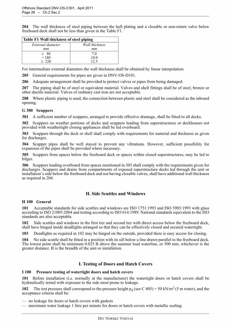
Offshore Standard DNV-OS-C301, April 2011 Page 28 – Ch.2 Sec.2
204 The wall thickness of steel piping between the hull plating and a closable or non-return valve belowfreeboard deck shall not be less than given in the Table F1.
For intermediate external diameters the wall thickness shall be obtained by linear interpolation.205 General requirements for pipes are given in DNV-OS-D101.206 Adequate arrangement shall be provided to protect valves or pipes from being damaged.207 The piping shall be of steel or equivalent material. Valves and shell fittings shall be of steel, bronze orother ductile material. Valves of ordinary cast iron are not acceptable.208 Where plastic piping is used, the connection between plastic and steel shall be considered as the inboardopening.
G 300 Scuppers301 A sufficient number of scuppers, arranged to provide effective drainage, shall be fitted to all decks.302 Scuppers on weather portions of decks and scuppers leading from superstructures or deckhouses notprovided with weathertight closing appliances shall be led overboard.303 Scuppers through the deck or shell shall comply with requirements for material and thickness as givenfor discharges.304 Scupper pipes shall be well stayed to prevent any vibrations. However, sufficient possibility forexpansion of the pipes shall be provided where necessary.305 Scuppers from spaces below the freeboard deck or spaces within closed superstructures, may be led tobilges.306 Scuppers leading overboard from spaces mentioned in 305 shall comply with the requirements given fordischarges. Scuppers and drains from compartments of exposed superstructure decks led through the unit orinstallation’s side below the freeboard deck and not having closable valves, shall have additional wall thicknessas required in 204.
H. Side Scuttles and Windows
H 100 General101 Acceptable standards for side scuttles and windows are ISO 1751:1993 and ISO 3903:1993 with glassaccording to ISO 21005:2004 and testing according to ISO 614:1989. National standards equivalent to the ISOstandards are also acceptable.102 Side scuttles and windows in the first tier and second tier with direct access below the freeboard deck,shall have hinged inside deadlights arranged so that they can be effectively closed and secured watertight.103 Deadlights as required in 102 may be hinged on the outside, provided there is easy access for closing.104 No side scuttle shall be fitted in a position with its sill below a line drawn parallel to the freeboard deck.The lowest point shall be minimum 0.025 B above the summer load waterline, or 500 mm, whichever is thegreater distance. B is the breadth of the unit or installation.
I. Testing of Doors and Hatch Covers
I 100 Pressure testing of watertight doors and hatch covers101 Before installation (i.e. normally at the manufacturer) the watertight doors or hatch covers shall behydraulically tested with exposure to the side most prone to leakage.102 The test pressure shall correspond to the pressure height pd (see C 405) + 50 kN/m2 (5 m water), and theacceptance criteria shall be:
— no leakage for doors or hatch covers with gaskets— maximum water leakage 1 litre per minute for doors or hatch covers with metallic sealing.
Table F1 Wall thickness of steel pipingExternal diameter
mmWall thickness
mm≤ 80= 180≥ 220
7.010.012.5
DET NORSKE VERITAS

Offshore Standard DNV-OS-C301, April 2011Ch.2 Sec.2 – Page 29
I 200 Hose testing of watertight and weathertight doors and hatch covers201 After installation onboard all (every single) watertight and weathertight doors or hatch covers shall behose tested. The water pressure shall be at least 0.2 N/mm2 (2 bar), and the nozzle shall be held at a distanceof maximum 1.5 m from the door or hatch cover. No leakage shall be accepted.As an alternative to hose testing, chalk testing may be applied under special circumstances upon acceptance byall parties involved.
I 300 Function testing of watertight doors and hatch covers301 After installation onboard the operation, control and alarm functions for all watertight doors and hatchcovers shall be tested.The following shall be verified:
a) It shall be possible to close all doors or hatch covers in one group simultaneously within 60 s from thecontrol room.
b) It shall be possible to open and close the doors or hatch covers three times by means of a local device andstored energy.
c) It shall be possible for a person to pass through the doorway or hatchway and at the same time hold bothhandles in the “open position”.
d) It shall be possible to open the door or hatch cover locally from both sides, after being closed centrally, andthe door or hatch cover shall close automatically after such opening.
e) The door or hatch cover shall be mechanically locked in closed position.f) The light and sound signals shall give warning when the door or hatch cover is closed centrally.g) The remote position indicator for doors or hatch covers shall function properly.h) The alarms for the following conditions shall function properly:
— start of standby pump— loss of power to control, alarm and indicating system— low pressure (below lowest permissible).
J. Closing Arrangements for Doors and Hatch CoversJ 100 Description of waterlines (beach lines)101 The following waterlines are required for Column-stabilised and Self-elevating units in order to indicatethe extent of the watertight and weathertight integrity:
— Waterline A (watertight); waterline showing equilibrium position at first intercept between righting andwind heeling moment curves in damage condition.
— Waterline B (weathertight for column-stabilised units); waterline according to area requirement of rightingand wind heeling moment curves (Ch.2 Sec.2 D301), the 7 degrees range criterion (Ch.2 Sec.2 E401 3),and the 4 meters criterion (Ch.2 Sec.2 E401 2), whichever is the most severe.
— Waterline B (weathertight for Self-elevating units); waterline according to area requirement of righting andwind heeling moment curves (Ch.2 Sec.2 D401).Guidance note:The beach lines required above can be omitted if all relevant openings are included in the stability calculations withthe correct positions.
---e-n-d---of---G-u-i-d-a-n-c-e---n-o-t-e---
J 200 Description of location of openings201 The location of openings in relation to the waterlines are defined as (see Figure 1):
I Internal openings in watertight bulkheads, i.e. internal bulkheads assumed watertight in stabilitycalculations.
II External openings below deepest draught according to ICLL 1966.III External openings between deepest draught and freeboard deck.IV External openings above freeboard deck, submerged before equilibrium position at first intercept (line A)
between righting and wind heeling moment curves in damage condition.V External openings:
1) on first and second tier2) submerged between equilibrium position at first intercept (line A) and waterline B.
DET NORSKE VERITAS
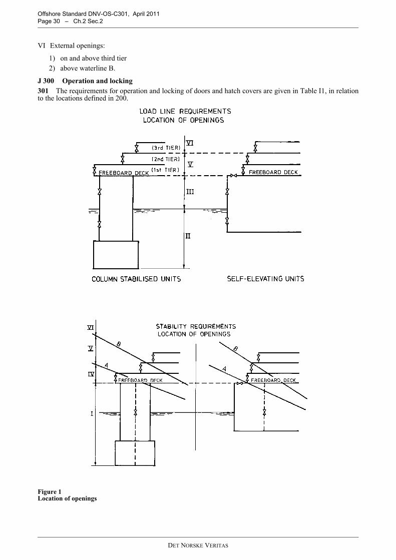
Offshore Standard DNV-OS-C301, April 2011 Page 30 – Ch.2 Sec.2
VI External openings:
1) on and above third tier2) above waterline B.
J 300 Operation and locking301 The requirements for operation and locking of doors and hatch covers are given in Table I1, in relationto the locations defined in 200.
Figure 1 Location of openings
DET NORSKE VERITAS
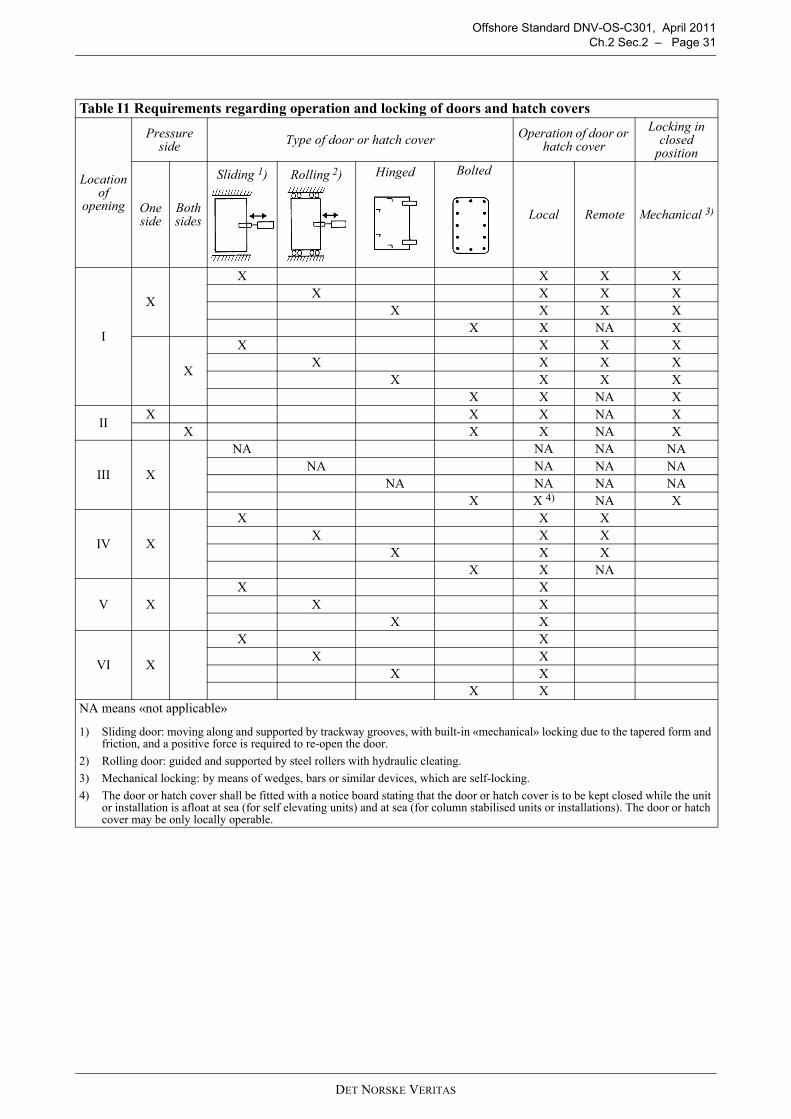
Offshore Standard DNV-OS-C301, April 2011Ch.2 Sec.2 – Page 31
Table I1 Requirements regarding operation and locking of doors and hatch covers
Locationof
opening
Pressure side Type of door or hatch cover Operation of door or
hatch coverLocking in
closed position
Oneside
Bothsides
Sliding 1) Rolling 2) Hinged Bolted
Local Remote Mechanical 3)
I
X
X X X XX X X X
X X X XX X NA X
X
X X X XX X X X
X X X XX X NA X
II X X X NA XX X X NA X
III X
NA NA NA NANA NA NA NA
NA NA NA NAX X 4) NA X
IV X
X X XX X X
X X XX X NA
V XX X
X XX X
VI X
X XX X
X XX X
NA means «not applicable»
1) Sliding door: moving along and supported by trackway grooves, with built-in «mechanical» locking due to the tapered form and friction, and a positive force is required to re-open the door.
2) Rolling door: guided and supported by steel rollers with hydraulic cleating.3) Mechanical locking: by means of wedges, bars or similar devices, which are self-locking.4) The door or hatch cover shall be fitted with a notice board stating that the door or hatch cover is to be kept closed while the unit
or installation is afloat at sea (for self elevating units) and at sea (for column stabilised units or installations). The door or hatch cover may be only locally operable.
DET NORSKE VERITAS
OFFSHORE STANDARDDNV-OS-C301
STABILITY AND WATERTIGHT INTEGRITY
CHAPTER 3
CERTIFICATION AND CLASSIFICATION
CONTENTS PAGE
Sec. 1 General............................................................................................................................... 31
DET NORSKE VERITASVeritasveien 1, NO-1322 Høvik, Norway Tel.: +47 67 57 99 00 Fax: +47 67 57 99 11

Offshore Standard DNV-OS-C301, April 2011 Page 33 – Ch.3 Sec.1
SECTION 1GENERAL
A. IntroductionA 100 Application101 As well as representing DNV’s recommendations on safe engineering practice for general use by theoffshore industry, the offshore standards also provide the technical basis for DNV classification, certificationand verification services.102 A complete description of principles, procedures, applicable class notations and technical basis foroffshore classification is given by the offshore service specifications for classification, see Table A1.
B. Design Review
B 100 Documentation requirements101 Documentation for classification shall be in accordance with the NPS DocReq (DNV NauticusProduction System for documentation requirements) and DNV-RP-A201.
B 200 Specific classification requirements201 Freeboard, see Ch.2 Sec.2 EThe computation of freeboard is not subject to classification. However, the requirements, including thoserelating to certification, of the International Convention on Load Lines 1966 (ILLC 1966) apply to all units andinstallations.
C. Certification of Materials and ComponentsC 100 General101 The product certification is a conformity assessment normally including both design and productionassessment.The production assessment includes inspection and testing during production and/or of the final product.102 Components shall be certified consistent with its functions and importance for safety. The principles ofcategorisation of component certification are given in the relevant offshore service specifications, see TableA1. 103 Product certification shall be documented by the following types of documents:
a) Det Norske Veritas Product Certificate (NV):A document signed by a DNV surveyor stating:
— conformity with rules and standard requirements— that tests are carried out on the certified product itself— that tests are made on samples taken from the certified product itself— that tests are performed in presence of the surveyor or in accordance with special agreements.
b) Works Certificate (W):A document signed by the manufacturer stating:
— conformity with rules and standard requirements— that tests are carried out on the certified product itself— that tests are made on samples taken from the certified product itself— that tests are witnessed and signed by a qualified department of the manufacturers.
c) Test Report (TR):
Table A1 DNV Offshore Service SpecificationsNo. TitleDNV-OSS-101 Rules for Classification of Offshore Drilling and Support UnitsDNV OSS-102 Rules for Classification of Floating Production, Storage and Loading UnitsDNV-OSS-103 Rules for Classification of LNG/LPG Floating Production and Storage Units or Installations
DET NORSKE VERITAS
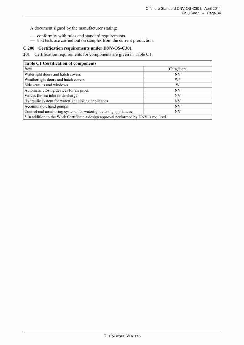
Offshore Standard DNV-OS-C301, April 2011Ch.3 Sec.1 – Page 34
A document signed by the manufacturer stating:
— conformity with rules and standard requirements— that tests are carried out on samples from the current production.
C 200 Certification requirements under DNV-OS-C301201 Certification requirements for components are given in Table C1.
Table C1 Certification of componentsItem CertificateWatertight doors and hatch covers NVWeathertight doors and hatch covers W*Side scuttles and windows WAutomatic closing devices for air pipes NVValves for sea inlet or discharge NVHydraulic system for watertight closing appliances NVAccumulator, hand pumps NVControl and monitoring systems for watertight closing appliances NV* In addition to the Work Certificate a design approval performed by DNV is required.
DET NORSKE VERITAS