DNV-OS-C103 Structural design of column stabilised units ...
57
OFFSHORE STANDARDS DNV-OS-C103 Edition July 2020 Amended August 2021 Structural design of column stabilised units - LRFD method The PDF electronic version of this document available at the DNV website dnv.com is the official version. If there are any inconsistencies between the PDF version and any other available version, the PDF version shall prevail. DNV AS
Transcript of DNV-OS-C103 Structural design of column stabilised units ...

OFFSHORE STANDARDS
DNV-OS-C103 Edition July 2020Amended August 2021
Structural design of column stabilised units- LRFD method
The PDF electronic version of this document available at the DNV website dnv.com is the official version. If thereare any inconsistencies between the PDF version and any other available version, the PDF version shall prevail.
DNV AS

FOREWORD
DNV offshore standards contain technical requirements, principles and acceptance criteria relatedto classification of offshore units.
© DNV AS July 2020
Any comments may be sent by e-mail to [email protected]
This service document has been prepared based on available knowledge, technology and/or information at the time of issuance of thisdocument. The use of this document by other parties than DNV is at the user's sole risk. DNV does not accept any liability or responsibilityfor loss or damages resulting from any use of this document.

CHANGES – CURRENT
This document supersedes the July 2015 edition of DNVGL-OS-C103.The numbering and/or title of items containing changes is highlighted in red.
Amendments August 2021
Topic Reference Description
Rebranding to DNV All This document has been revised due to the rebranding of DNVGL to DNV. The following have been updated: the companyname, material and certificate designations, and references toother documents in the DNV portfolio. Some of the documentsreferred to may not yet have been rebranded. If so, please seethe relevant DNV GL document. No technical content has beenchanged.
Changes July 2020
Topic Reference Description
Clarification of assumptionsand applications
Ch.1 Sec.1 [1.3] Clarified assumptions and applications for this offshorestandard.
Structural categorisation ofmain loadbearing internalstructure
Ch.2 Sec.1 [2] Defined internal structure forming an integral part of the globalstructural strength as primary category.
Material selection also toconsider conditions notcovered in this standard
Ch.2 Sec.1 [3.1.2] Clarified that conditions not covered by the standard shall beconsidered when deciding the material grades.
Through thickness properties Ch.2 Sec.1 [3.1.3] Added typical areas to have Z-quality and guidance on thestress level through the plate requiring Z-quality plates in otherareas.
Inspection of welds in areashaving difficult/limited accessduring fabrication
Ch.2 Sec.1 [4.1.2] Clarified that inspection category I is required for welds withdifficult or limited access during fabrication.
Impact of fabrication scheduleon NDT scope
Ch.2 Sec.1 [4.1.3] Included that welding assembly and the complexity of the job isto be considered when determining extent of inspection.
Inspection of all welds tobe shown on the inspectioncategory plan
Ch.2 Sec.1 [5.1.2] Included reference to DNV-OS-C101 and the inspectionrequirements of the weld.
Structural integrity in way ofpontoon column connections
Ch.2 Sec.1 [5.1.3] Included that structural integrity of the members in theconnection shall be ensured.
Details of structural andinspection categorisation inway of connections
Ch.2 Sec.1 [5.1.4]Ch.2 Sec.1 Figure 5
Ch.2 Sec.1 Figure 6
Clarified that structural and inspection categories to be appliedin for the stiffeners, plates and brackets in typical connectionsare shown in figures.
Changes - current
Offshore standards — DNV-OS-C103. Edition July 2020, amended August 2021 Page 3Structural design of column stabilised units - LRFD method
DNV AS

Topic Reference Description
Removal of redundant text andinclude an objective for thesection
Ch.2 Sec.2 [1] Added Ch.2 Sec.2 [1.1] Objective for easier understanding anddeleted old Ch.2 Sec.2 [2.1] Load point.
Removal of redundant text Ch.2 Sec.2 [3.1.4] Deleted text that is described elsewhere in the document.
Clarification of tank loadcombinations and external seapressure
Ch.2 Sec.2 [3.2.5] Added requirement for combination of tank filling and seapressure.
The maximum sea pressurein ULS is in function of thecalculated upwelling of thewave (air gap)
Ch.2 Sec.2 [4.2.2] Changed the definition of DD in the formula for calculation ofsea pressure to consider the maximum upwelling for units withnegative air gap.Added a minimum value of 25 kN/m2 for environmental seapressure.
Windprofile for units intendedfor world-wide operation
Ch.2 Sec.2 [4.3.7] Added the wind profile to be used for units intended for world-wide operation is the Frøya-wind profile in DNV-RP-C205.
Extreme value of motionresponses in short termanalysis
Ch.2 Sec.3 [2.1.2] Clarified the 90% fractile shall be used for extreme value ofmotion responses in short term analysis.
Model test Ch.2 Sec.3 [2.1.3] Added requirement for model tests for new types of units.
Air gap requirements inoperating draught
Ch.2 Sec.3 [4.1.3] Added criteria for dynamic air gap in operating draught.Zero air gap at the deck box lower edge shall be assumed inoperating draught.
Minimum lateral pressureloads for deck box bottom
Ch.2 Sec.3 [4.1.4] Clarified that minimum lateral pressure shall be considered onthe deck box bottom.
Loads from run-up Ch.2 Sec.3 [4.1.5] Clarified that run-up around the columns shall be considered byassuming a static pressure of 400 kN/m2.
Minimum pressure on outwardfacing bulkheads of deckstructure
Ch.2 Sec.3 [4.1.6] Clarified that the minimum pressure acting on outward facingbulkheads of the deck structure and parts of the upper hulldeck houses is set to 25 kN/m2.
Impact pressure acting oncolumn shell.
Ch.2 Sec.3 [4.1.7] Added a static pressure of 250 kN/m2 for the outward facingsides of the columns.
Position of weak equipment inareas prone to wave load
Ch.2 Sec.3 [4.1.9] Critical equipment should not be in area where wave impactand green sea occurs.
Heeled condition to includeone-compartment damage
Ch.2 Sec.5 [6.1.1] Clarified that in case the actual damage water lines from thestability calculations are used for the calculation of the externalwater pressure in the heeled condition, a heeling of 25 deg forthe heeled condition shall be used.
Removal of required loads thatare not possible or difficult toestimate
Ch.2 Sec.5 [6.1.3] Requirements to equipment and appurtenances in areas givenin Ch.2 Sec.3 [4.1.9].
Drilling operation loads Ch.2 Sec.6 [1.2.2] Clarified that governing loads from drilling operation shall beconsidered in the redundancy analysis of the vertical diagonalbraces.
Changes - current
Offshore standards — DNV-OS-C103. Edition July 2020, amended August 2021 Page 4Structural design of column stabilised units - LRFD method
DNV AS

Topic Reference Description
Coupling between design andfabrication requirements
Ch.2 Sec.6 [3.1.1] Added reference to the DNV-RP-C203 with examples offabrication requirements depending on the SN-curves chosen inthe design phase.
Global model for benign water App.B Table 1 Clarified that hybrid model Sink source and Morison (whenrelevant, for calculation of drag forces) is also applicable for twopontoon column stabilised units in benign water.
Estimate of ice pressure inship rules gives unrealistichigh values.
App.C [2.2.4] Added applicable k1-factor for pressure calculations defined forunits with velocities less than 5 knots to get more realistic icepressures on column stabilize units of typical design.
Editorial correctionsIn addition to the above stated changes, editorial corrections may have been made.
Changes - current
Offshore standards — DNV-OS-C103. Edition July 2020, amended August 2021 Page 5Structural design of column stabilised units - LRFD method
DNV AS

CONTENTS
Changes – current............................................................3
Chapter 1 Introduction..................................................... 8Section 1 Introduction.........................................................................................................8
1 General.................................................................................................................8
2 References........................................................................................................... 9
3 Definitions..........................................................................................................10
4 Symbols..............................................................................................................10
Chapter 2 Technical content........................................... 12Section 1 Structural categorisation, material selection and inspection principles..............12
1 General...............................................................................................................12
2 Structural categorisation....................................................................................12
3 Material selection...............................................................................................13
4 Inspection categories.........................................................................................14
5 Categorisation and inspection level for typical column-stabilised unit details.... 14
Section 2 Design loads...................................................................................................... 20
1 General...............................................................................................................20
2 Permanent loads (G)..........................................................................................20
3 Variable functional loads (Q).............................................................................20
4 Environmental loads (E).................................................................................... 22
5 Deformation loads (D)....................................................................................... 24
6 Accidental loads (A)...........................................................................................25
7 Fatigue loads......................................................................................................25
8 Combination of loads......................................................................................... 25
Section 3 Ultimate limit states (ULS)................................................................................ 26
1 General...............................................................................................................26
2 Method of analyses............................................................................................ 27
3 Scantlings and weld connections....................................................................... 28
4 Air gap............................................................................................................... 29
Section 4 Fatigue limit states (FLS).................................................................................. 32
1 General...............................................................................................................32
2 Fatigue Analyses................................................................................................ 33
Section 5 Accidental limit states (ALS)............................................................................. 36
1 General...............................................................................................................36
2 Collision..............................................................................................................36
Contents
Offshore standards — DNV-OS-C103. Edition July 2020, amended August 2021 Page 6Structural design of column stabilised units - LRFD method
DNV AS
3 Dropped object.................................................................................................. 36
4 Fire.....................................................................................................................37
5 Explosion............................................................................................................37
6 Heeled condition................................................................................................ 37
Section 6 Special considerations....................................................................................... 39
1 Redundancy........................................................................................................39
2 Support of mooring equipment, towing brackets etc......................................... 39
3 Structural details............................................................................................... 39
Chapter 3 Classification and certification........................41Section 1 Classification......................................................................................................41
1 General...............................................................................................................41
Appendix A Column stabilised installations.....................431 Introduction.......................................................................................... 432 Fatigue.................................................................................................. 43
Appendix B Methods and models for designs..................451 Methods and models............................................................................. 45
Appendix C Strength requirements for transit in ice....... 471 General..................................................................................................472 Ice design loads..................................................................................513 Shell plating..........................................................................................524 Frames.................................................................................................. 535 Special arrangement............................................................................. 54
Changes – historic..........................................................56
Contents
Offshore standards — DNV-OS-C103. Edition July 2020, amended August 2021 Page 7Structural design of column stabilised units - LRFD method
DNV AS
CHAPTER 1 INTRODUCTION
SECTION 1 INTRODUCTION
1 General
1.1 GeneralThis offshore standard provides requirements and guidance for the structural design of column-stabilisedunits constructed in steel.
1.2 ObjectivesThe objectives of this standard are to:
— provide an internationally acceptable standard of safety by defining minimum requirements for design ofcolumn-stabilised units
— serve as a contractual reference document between suppliers, purchasers, and certification— serve as a guideline for designers, suppliers, purchasers and regulators— specify procedures and requirements for column-stabilised units subject to DNV verification andclassification.
1.3 Assumptions and applications
1.3.1 A column-stabilised unit is a buoyant structure engaged in operations not intended for service at oneparticular location, and which can be relocated without major dismantling or modification.
1.3.2 A column-stabilised installation is a buoyant structure that remains on location for a prolonged periodof time.
Guidance note:
Throughout this standard the term 'unit' is used as a general term covering requirements for both units and installations, exceptwhere the term 'installation' is used to highlight additional or different requirements that only applies to installations.
---e-n-d---o-f---g-u-i-d-a-n-c-e---n-o-t-e---
1.3.3 The requirements and guidance documented in this standard are generally applicable to allconfigurations of column-stabilised units, typically configured by decks, columns, bracing members, andpontoons.
1.3.4 A column-stabilised unit shall be designed in compliance with the overall safety principles given inDNV-OS-C101 Ch.2 Sec.1.
1.3.5 A column-stabilised unit or installation may be kept on location by either a position mooring system ora dynamic positioning system, or a combination of these methods. Column stabilised units may be designedto rest on the sea-bed.
1.3.6 A column-stabilised unit should be designed to operate in a variety of modes, e.g. transit, operatingand survival. Limiting design criteria for the modes of operation shall be clearly defined and documented.Such limiting design criteria shall include relevant considerations of the following items:
— intact condition, structural strength— damaged condition, structural strength
Chapter 1 Section 1
Offshore standards — DNV-OS-C103. Edition July 2020, amended August 2021 Page 8Structural design of column stabilised units - LRFD method
DNV AS
— negative/positive air gap— areas affected by wave impact and green sea— areas and appurtenances (e.g. piping, air inlets, ducts, cabling.) affected by wave action (if negative airgap)
— accelerations (fastening of equipment)— watertight integrity and hydrostatic stability.
1.3.7 For new designs, and/or unproved design applications of designs where limited or no direct experienceexists, relevant analyses and model testing, shall be performed in order to demonstrate that an acceptablelevel of safety is obtained.
1.3.8 The standard has been written for general world-wide operation. Governmental regulations may specifyrequirements in excess of the provisions given by this standard depending on the size, type, location andintended service of an offshore unit or installation.
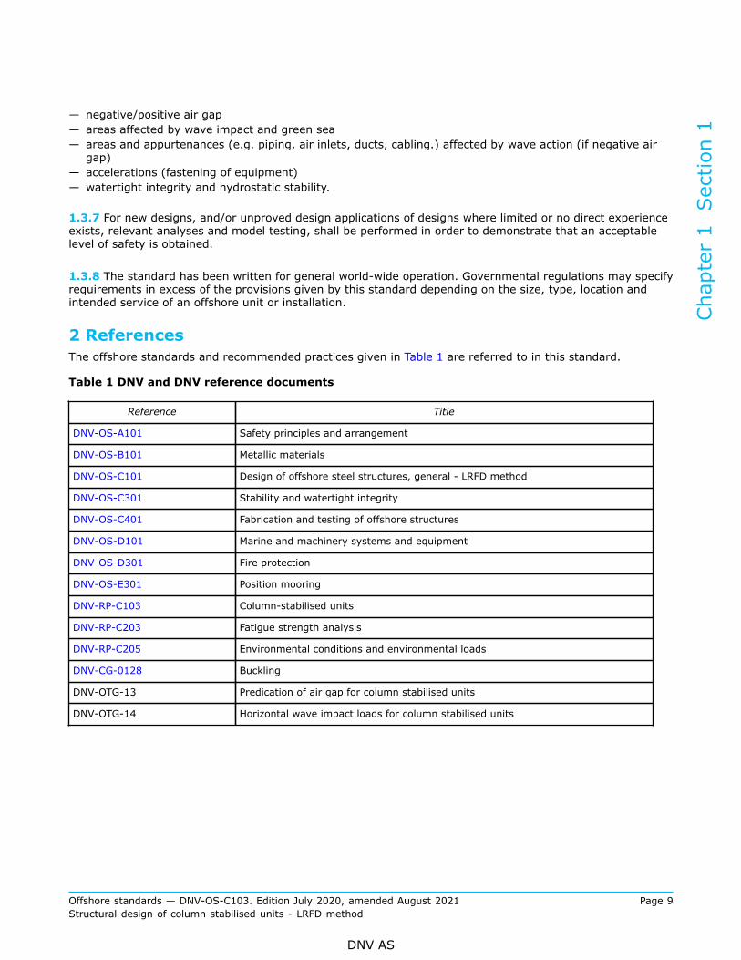
2 ReferencesThe offshore standards and recommended practices given in Table 1 are referred to in this standard.
Table 1 DNV and DNV reference documents
Reference Title
DNV-OS-A101 Safety principles and arrangement
DNV-OS-B101 Metallic materials
DNV-OS-C101 Design of offshore steel structures, general - LRFD method
DNV-OS-C301 Stability and watertight integrity
DNV-OS-C401 Fabrication and testing of offshore structures
DNV-OS-D101 Marine and machinery systems and equipment
DNV-OS-D301 Fire protection
DNV-OS-E301 Position mooring
DNV-RP-C103 Column-stabilised units
DNV-RP-C203 Fatigue strength analysis
DNV-RP-C205 Environmental conditions and environmental loads
DNV-CG-0128 Buckling
DNV-OTG-13 Predication of air gap for column stabilised units
DNV-OTG-14 Horizontal wave impact loads for column stabilised unitsChapter 1 Section 1
Offshore standards — DNV-OS-C103. Edition July 2020, amended August 2021 Page 9Structural design of column stabilised units - LRFD method
DNV AS

3 Definitions
3.1 Verbal forms
Table 2 Verbal forms
Term Definition
shall verbal form used to indicate requirements strictly to be followed in order to conform to the document
should verbal form used to indicate that among several possibilities one is recommended as particularly suitable,without mentioning or excluding others
may verbal form used to indicate a course of action permissible within the limits of the document
3.2 Terms
3.2.1 Transit conditions: all unit movements from one geographical location to another.
3.2.2 Standard terms are given in DNV-OS-C101.
4 Symbols
4.1 Latin characters
= the intercept of the design S-N curve with the log N axis
ah = horizontal acceleration
av = vertical acceleration
g0 = 9.81 m/s2 acceleration due to gravity
h = Weibull shape parameter
hop = vertical distance from the load point to the position of maximum filling height
M = mass of cargo, equipment or other components
m = the inverse slope of the S-N curve
n0 = total number of stress fluctuations during the lifetime of the structure
nI = number of stress fluctuations in I years
pd = design pressure
pdyn = pressure head due to flow through pipes
zb = vertical distance in m from the moulded baseline to the load point
Cw = reduction factor due to wave particle motion (Smith effect)
DD = vertical distance from the moulded baseline to the underside of the deck structure
DFF = design fatigue factor
PHd = horizontal design force
PVd = vertical design force
Chapter 1 Section 1
Offshore standards — DNV-OS-C103. Edition July 2020, amended August 2021 Page 10Structural design of column stabilised units - LRFD method
DNV AS

TE = extreme operating draught measured vertically from the moulded baseline to the assigned loadwaterline.
4.2 Greek characters
Γ = gamma function
α = angle
ρ = density
γc = contingency factor
τd = nominal design shear stress in the girder adjusted for cut-outs
γf = partial load factor
γf,E = partial load factor for environmental loads
γf,G,Q = partial load factor for functional and variable loads.
4.3 AbbreviationsAbbreviations used in this standard are given in DNV-OS-C101.
Chapter 1 Section 1
Offshore standards — DNV-OS-C103. Edition July 2020, amended August 2021 Page 11Structural design of column stabilised units - LRFD method
DNV AS

CHAPTER 2 TECHNICAL CONTENT
SECTION 1 STRUCTURAL CATEGORISATION, MATERIAL SELECTIONAND INSPECTION PRINCIPLES
1 General
1.1 Scope
1.1.1 This section describes the structural categorisation, selection of steel materials and inspectionprinciples to be applied in design, fabrication and testing of column-stabilised units.
1.1.2 The application of structural categories are determined based on the structural significance,consequences of failure and the complexity of the joints. The structural application category determines theselection of steel quality and the inspection extent of the welds.
1.1.3 The steel grades selected for structural components shall be related to weldability and requirements fortoughness properties and shall be in compliance with the requirements given in the DNV-OS-B101.
2 Structural categorisationApplication categories for structural components are defined in DNV-OS-C101 Ch.2 Sec.3. Structuralmembers of column-stabilised units are grouped as follows:Special category
a) Portions of deck plating, heavy flanges, and bulkheads within the upper hull or platform which form 'box'or 'I' type supporting structure which receive major concentrated loads.
b) External shell structure in way of intersections of vertical columns, decks and lower hulls.c) Major intersections of bracing members.d) Material with 'through' thickness properties (z-quality) used at connections of vertical columns, upper
platform decks and upper or lower hulls which are designed to provide proper alignment and adequateload transfer.
e) External brackets, portions of bulkheads, and frames which are designed to receive concentrated loads atintersections of major structural members.
f) Areas of concentrated loads in elements of supporting structure, such as anchor line fairleads, winches,crane pedestals, flare, derricks, drillfloor, etc.
Figure 1 to Figure 4 show typical examples of special structures.Primary category
a) Deck plating, heavy flanges, and bulkheads within the upper hull or platforms which form 'box' or 'I'types of major structural members which do not receive major concentrated loads.
b) External shell structure of vertical columns, pontoons, braces, and upper hulls.c) Internal structure forming an integral part of the global structural strength.d) Bulkheads, decks, stiffeners and girders which provide local reinforcement or continuity of structure in
way of intersections, except areas where the structure is considered for special application.e) Main support structure of heavy substructures and equipment, e.g. anchor line fairleads, cranes,
drillfloor substructure, life boat platform, thruster foundation and helicopter deck, except areas receivingconcentrated loads which are considered as special application.
Secondary category
Chapter 2 Section 1
Offshore standards — DNV-OS-C103. Edition July 2020, amended August 2021 Page 12Structural design of column stabilised units - LRFD method
DNV AS

a) Upper platform decks, or decks of upper hulls except areas where the structure is considered primary orspecial application.
b) Bulkheads, stiffeners, flats or decks and girders in vertical columns, decks, pontoons, diagonal andhorizontal bracing, which are not considered as primary or special application.
c) Deckhouses not being part of global structural strength.d) Other structures not categorised as special or primary.
3 Material selection
3.1 General
3.1.1 Material specifications shall be established for all structural materials. Such materials shall be suitablefor their intended purpose and have adequate properties in all relevant design conditions. Material selectionshall be undertaken in accordance with the principles given in DNV-OS-C101.
3.1.2 When considering criteria appropriate to material grade selection, due consideration shall be given toall relevant phases in the life cycle of the unit. In this connection there may be temporary conditions andcriteria, other than those described by this standard, and/or that are specified from the in-service operationalphase, that provide more severe design requirements in respect to design and selection of material.
Guidance note:
Such criteria may, for example, be design temperature and/or stress levels during marine operations.
---e-n-d---o-f---g-u-i-d-a-n-c-e---n-o-t-e---
3.1.3 In structural cross-joints essential for the overall structural integrity, where tensile stresses are actingnormal to the plane of the plate, the plate material shall be tested to prove the ability to resist lamellartearing (Z-quality).Typical main areas involving cross-joints where z-quality is required irrespective of stress level through theplate are:
— intersection between pontoon and column— intersection between column and deck structure— at critical intersections and complex joints of bracings— at critical intersections and complex joints of heavy supporting structures (such as drill floors, flaretowers, fairleads, crane pedestals, helidecks, lifeboat platforms.)
For other areas the limit for tensile stress is normally 50% of the material's yield stress for the base material.
3.1.4 Material designations and requirements for application are defined in DNV-OS-C101 Ch.2 Sec.3.
3.2 Design and service temperatures
3.2.1 The design temperature for a unit is the reference temperature for assessing areas where the unit canbe transported, installed and operated. The design temperature shall be lower or equal to the lowest meandaily average temperature in air for the relevant areas. For seasonal restricted operations the lowest meandaily average temperature in air for the season may be applied.
3.2.2 The service temperatures for different parts of a unit apply for selection of structural steel. The servicetemperatures are defined in [3.2.3] to [3.2.6]. If different service temperatures than what is defined in[3.2.3] to [3.2.6] are specified for a structural part, then the lower specified value shall be applied.
Chapter 2 Section 1
Offshore standards — DNV-OS-C103. Edition July 2020, amended August 2021 Page 13Structural design of column stabilised units - LRFD method
DNV AS

3.2.3 External structures above the light transit waterline shall not be designed for a service temperaturehigher than the design temperature for the unit.However, for column-stabilised units of conventional type, the pontoon deck is not required to be designedfor a service temperature lower than 0ºC.For units intended to navigate in ice conditions, see App.C.
3.2.4 External structures below the light transit waterline need not be designed for a service temperaturelower than 0ºC.
3.2.5 Internal structures of columns, pontoons and decks shall have the same service temperature as theadjacent external structure, if not otherwise documented.
3.2.6 Internal structures in way of permanently heated rooms need not to be designed for a servicetemperature lower than 0ºC.
4 Inspection categories
4.1 General
4.1.1 Welding and the extent of non-destructive testing during fabrication, shall be in accordance with therequirements stipulated for the appropriate inspection category as defined in DNV-OS-C101 Ch.2 Sec.3.
4.1.2 Inspection categories determined in accordance with DNV-OS-C101 Ch.2 Sec.3 provide requirementsfor the minimum extent of required inspection. Complex connections with limited or difficult fabricationaccess shall be particularly considered with respect to non-destructive testing methods and its abilities ofthe methods to detect defects likely to occur. Such areas shall be inspected during fabrication according toinspection category I and shall be clearly identified on the inspection category plan.
4.1.3 When determining the extent of inspection and the locations of required NDT, in addition to evaluatingdesign parameters (for example fatigue utilisation), consideration should be given to relevant fabricationparameters including:
— location of block (section) joints— welding assembly and complexity of the welding job— manual versus automatic welding— start and stop of weld, etc.
5 Categorisation and inspection level for typical column-stabilisedunit details
5.1 General
5.1.1 Figure 1 to Figure 4 illustrate minimum requirements for structural categorisation and extent ofinspection for typical column-stabilised unit configurations.
5.1.2 All relevant welds described in DNV-OS-C101 Ch.2 Sec.3 [3.3] shall be identified for inclusion in theinspection category plan.
Chapter 2 Section 1
Offshore standards — DNV-OS-C103. Edition July 2020, amended August 2021 Page 14Structural design of column stabilised units - LRFD method
DNV AS

5.1.3 Connections in way of pontoon and column, as indicated in Figure 1 and Figure 2, shall be designedwith due regard to the structural integrity of cross-joints, landings of adjoining striffeners and bulkheads.Continuous material of cross-joints shall be provided with through-thickness properties (Z-quality material).
5.1.4 The shaded areas indicated in Figure 1 to Figure 4 are intended to be three-dimensional and assumedextended into the structure. Stiffeners and brackets welded to the plate at connections in special and primaryareas shall be welded with full penetration welds, as shown in the examples of Figure 1, Figure 2 and Figure4 to Figure 6, and no notches shall be used.
5.1.5 The inspection categories for general pontoon, plate butt welds and girder welds to the pontoon shellshall be determined based upon, amongst others, accessibility and ULS/FLS utilisation.
5.1.6 Major bracket toes should be designated as locations with a mandatory requirement for MPI. Inway of the brace connections as indicated Figure 3, the brace and brace bracket plate fields should be thecontinuous material. These plate fields shall be of material with through-thickness properties (Z-qualitymaterial).
5.1.7 In way of the column and upper hull connection as indicated in Figure 4 the upper hull deck plateshould be the continuous material. These plate fields shall be of material with through-thickness properties(Z-quality material).
1) This is normally fatigue critical, an hence the inspection category shall be increased from II to I, see DNV-OS-C101 Ch.2 Sec.3 [3.3.5].
Figure 1 Structural and inspection categories of pontoon and column connection, twin pontoondesign
Chapter 2 Section 1
Offshore standards — DNV-OS-C103. Edition July 2020, amended August 2021 Page 15Structural design of column stabilised units - LRFD method
DNV AS

Figure 2 Structural and inspection categories of column and ring pontoon connection, ring-pontoon design
Figure 3 Structural and inspection categories of brace connectionChapter 2 Section 1
Offshore standards — DNV-OS-C103. Edition July 2020, amended August 2021 Page 16Structural design of column stabilised units - LRFD method
DNV AS

Figure 4 Structural and inspection categories of column and upper hull connection
Chapter 2 Section 1
Offshore standards — DNV-OS-C103. Edition July 2020, amended August 2021 Page 17Structural design of column stabilised units - LRFD method
DNV AS

Figure 5 Welding integrity and inspection categories of pontoon and column connection in specialarea
Chapter 2 Section 1
Offshore standards — DNV-OS-C103. Edition July 2020, amended August 2021 Page 18Structural design of column stabilised units - LRFD method
DNV AS

Figure 6 Welding integrity and inspection categories of pontoon and column connection in primaryarea
Chapter 2 Section 1
Offshore standards — DNV-OS-C103. Edition July 2020, amended August 2021 Page 19Structural design of column stabilised units - LRFD method
DNV AS

SECTION 2 DESIGN LOADS
1 General
1.1 Objective
1.1.1 The objective of this section is to provide provisions to load components and load combinations to beconsidered in the overall strength analysis as well as design pressures applicable for local design.
1.2 Application
1.2.1 Characteristic loads shall be used as reference loads. Design loads are, in general, defined in DNV-OS-C101 and described in DNV-RP-C103 and DNV-RP-C205.
2 Permanent loads (G)Permanent loads are loads that will not vary in magnitude, position, or direction during the periodconsidered, and include:
— lightweight of the unit, including mass of permanently installed modules and equipment, such asaccommodation, helideck, drilling and production equipment
— hydrostatic pressures resulting from buoyancy— pretension in respect to mooring, drilling and production systems, e.g. mooring lines, risers, etc. SeeDNV-OS-E301.
3 Variable functional loads (Q)
3.1 General
3.1.1 Variable functional loads are loads that may vary in magnitude, position and direction during the periodunder consideration.
3.1.2 Except where analytical procedures or design specifications otherwise require, the value of the variableloads utilised in structural design shall be taken as either the lower or upper design value, whichever givesthe more unfavourable effect. Variable loads on deck areas for local design are given in DNV-OS-C101 Ch.2Sec.2 [4.2].
3.1.3 Variations in operational mass distributions, including variations in tank load conditions in pontoons,shall be adequately accounted for in the structural design.
3.1.4 Design criteria resulting from operational requirements shall be fully considered. Examples of suchoperations may be:
— drilling, production, workover, and combinations thereof— consumable re-supply procedures— maintenance procedures— possible mass re-distributions in extreme conditions.
Chapter 2 Section 2
Offshore standards — DNV-OS-C103. Edition July 2020, amended August 2021 Page 20Structural design of column stabilised units - LRFD method
DNV AS

3.2 Tank loads
3.2.1 A minimum design density (ρ) of 1.025 t/m3shall be considered in the determination of the requiredscantlings of tank structures.
3.2.2 The extent to which it is possible to fill sounding, venting or loading pipe arrangements shall be fullyaccounted for in determination of the maximum design pressure to which a tank may be subjected to.
3.2.3 Dynamic pressure heads resulting from filling of such pipes shall be included in the design pressurehead where such load components are applicable.
3.2.4 All relevant combinations of pressures due to filling of tanks and variation of the sea pressure shall betaken into account in design.
3.2.5 All tanks shall be designed for the following internal design pressure:
where:
av = maximum vertical acceleration, (m/s2), being the coupled motion response applicable tothe tank in question
hop = vertical distance (m) from the load point to the position of maximum filling height. Fortanks adjacent to the sea that are situated below the extreme operating draught (TE), hopshall not be taken less than from the load point to the static sea level. For tanks wherehop shall not be taken less than from the load point to the static sea level, and where thedensity of the content is higher than sea water, the pressure may be calculated assumingthe density of water from the maximum filling level to the still water level.Descriptions and requirements related to different tank arrangements are given in DNV-OS-D101 Ch.2 Sec.3 [3.3] and DNV-OS-D101 Ch.2 Sec.3 [5.2.1]
γf,G,Q = partial load factor, for permanent and functional loads see Sec.3 Table 1
γf,E = partial load factor for environmental loads, see Sec.3 Table 1.
Guidance note:
For preliminary design calculations, av may be taken as 0.3 g0.
---e-n-d---o-f---g-u-i-d-a-n-c-e---n-o-t-e---
3.2.6 For tanks where the air pipe may be filled during filling operations, the following additional internaldesign pressure conditions shall be considered:
pd = (ρ g0 hop + pdyn) γf,G,Q (kN/m2)where:pdyn = pressure (kN/m2) due to flow through pipes, minimum 25 kN/m2.
Guidance note:
This internal pressure needs not to be combined with extreme environmental loads. Normally only static global response needs tobe considered.
---e-n-d---o-f---g-u-i-d-a-n-c-e---n-o-t-e---
Chapter 2 Section 2
Offshore standards — DNV-OS-C103. Edition July 2020, amended August 2021 Page 21Structural design of column stabilised units - LRFD method
DNV AS

3.2.7 For external plate field boundaries the external pressure up to the lowest wave through heightoccurring in the environmental extreme condition, including relative motion of the unit shall be accounted for.
Guidance note:
The external pressure for external plate field boundaries may be taken up to half the pontoon height. See DNV-RP-C103 [3.8].
---e-n-d---o-f---g-u-i-d-a-n-c-e---n-o-t-e---
3.2.8 In cases where the maximum filling height is less than the height to the top of the air pipe, it shall beensured that the tank will not be overpressured during operation and tank testing conditions.
3.2.9 Requirements for testing of tank tightness and structural strength are given in DNV-OS-C401 Ch.2Sec.8.
4 Environmental loads (E)
4.1 General
4.1.1 General considerations for environmental loads are given in DNV-OS-C101 Ch.2 Sec.1 [5] and DNV-OS-C101 Ch.2 Sec.2, and DNV-RP-C205.
4.1.2 Combinations of environmental loads are stated in DNV-OS-C101 Ch.2 Sec.2 Table 4.
4.1.3 Typical environmental loads to be considered in the structural design of a column-stabilised unit are:
— wave loads, including variable pressure, inertia, wave 'run-up', and slamming loads— wind loads— current loads— snow and ice loads.
4.1.4 The following responses due to environmental loads shall be considered in the structural design of acolumn-stabilised unit:
— dynamic stresses for all limit states— rigid body motion, e.g. in respect to air gap and maximum angles of inclination— sloshing— slamming induced vibrations— vortex induced vibrations,e.g. resulting from wind loads on structural elements in a flare tower— environmental loads from mooring and riser system.
4.2 Sea pressures
4.2.1 For load conditions where environmental load effects shall be considered the pressures resulting fromsea loading shall include consideration of the relative motion of the unit.
4.2.2 The design sea pressure acting on the external shell of column-stabilised units in operating conditionsshall be taken as:
where:
Chapter 2 Section 2
Offshore standards — DNV-OS-C103. Edition July 2020, amended August 2021 Page 22Structural design of column stabilised units - LRFD method
DNV AS

and
, minimum 25 kN/m2
where:
TE = draught (m) measured vertically from the moulded baseline to the assigned load waterline. If theunit has more than one draught, the draught providing the highest pressure shall be used
Cw = reduction factor due to wave particle motion (Smith effect) Cw = 0.9 unless otherwisedocumented
DD = vertical distance in m from the moulded baseline to the underside of the deck structure for unitswith positive air gapThe largest relative distance from moulded baseline to the upwelling of the disturbed wave crestshall replace DD if this is proved larger, i.e. negative air gap. The maximum upwelling aroundcolumns shall be used for the entire unit
zb = vertical distance in m from the moulded baseline to the load point
ps = permanent sea pressure
pe = environmental sea pressure.
Guidance note:
For areas around the columns, the upwell may be calculated at positions with a distance of 0.2*D away from the vertical columnexternal surface, where D is the maximum cross-sectional dimension (diameter for circular column, width of square column).
---e-n-d---o-f---g-u-i-d-a-n-c-e---n-o-t-e---
4.2.3 When pressures are acting on both sides of bulkheads, the load factor shall be applied to the netpressure.
4.2.4 The Smith effect (Cw = 0.9) shall only be applied for the maximum wave crest elevation.
4.3 Wind loads
4.3.1 Wind loads shall be accounted for in the design of topside structures subject to significant windexposure, e.g. modules, equipment, exposed structures on deck etc. The mean wind speed over 1 minuteperiod at actual position above the sea level shall be used and combined with accelerations loads.
4.3.2 For structures where wind loads are governing, the mean wind speed period shall be reduced.Guidance note:
For structures not being sensitive to wind gusts a mean wind speed of 3 s may be used for structures with maximum dimension of50 m and 15 s for larger structures.
---e-n-d---o-f---g-u-i-d-a-n-c-e---n-o-t-e---
4.3.3 Fatigue assessments shall be carried out for structures where vortex-shedding may occur.
Chapter 2 Section 2
Offshore standards — DNV-OS-C103. Edition July 2020, amended August 2021 Page 23Structural design of column stabilised units - LRFD method
DNV AS

Guidance note:
It is recommended to design the structure so that the structure is not prone to vortex-shedding. See DNV-RP-C205 for furtherinformation.
---e-n-d---o-f---g-u-i-d-a-n-c-e---n-o-t-e---
4.3.4 The pressure acting on vertical bulkheads only exposed to wind shall not be less than 2.5 kN/m2,unless otherwise documented.
4.3.5 For units intended for unrestricted service (worldwide operation) a wind speed of v1min10m=51.5 m/s for 100 year return period will cover most locations. For installations intended for one specific offshorelocation the relevant site specific values shall be used.
Guidance note:
Wind speed values for some locations can be found in DNV-OS-E301 Ch.2 Sec.1 [2.3.4].
---e-n-d---o-f---g-u-i-d-a-n-c-e---n-o-t-e---
4.3.6 For units intended for world wide operation the wind profile as given in DNV-RP-C205 [2.3.2.11] maybe used. For installations intended for long term service at one offshore location appropriate wind profile shallbe used.
4.3.7 Further details regarding wind design loads are given in DNV-RP-C205.
4.4 Heavy componentsThe forces acting on supporting structures and lashing systems for rigid units of cargo, equipment or otherstructural components should be taken as:
For components exposed to wind, a horizontal force due to the design gust wind shall be added to PHd.
av = vertical acceleration (m/s2)
ah = horizontal acceleration (m/s2)
M = mass of cargo, equipment or other components (t)
PVd = vertical design force
PHd = horizontal design force.
Further considerations with respect to environmental loads are given in DNV-RP-C205.
5 Deformation loads (D)Deformation loads are loads caused by inflicted deformations, such as:
— temperature loads— built-in deformations— built-in excessive misalignments.
Further details and description of deformation loads are given in DNV-OS-C101 Ch.2 Sec.2 [8].
Chapter 2 Section 2
Offshore standards — DNV-OS-C103. Edition July 2020, amended August 2021 Page 24Structural design of column stabilised units - LRFD method
DNV AS

6 Accidental loads (A)The following ALS events shall be considered in respect to the structural design of a column-stabilised unit:
— collision— dropped objects, e.g. from crane handling— fire— explosion— unintended flooding.
Requirements and guidance on accidental loads are given in DNV-OS-C101 and generic loads are given inDNV-OS-A101.
7 Fatigue loads
7.1 General
7.1.1 Repetitive loads, which may lead to significant fatigue damage, shall be evaluated. The following listedsources of fatigue loads shall, as relevant, be considered:
— waves (including those loads caused by slamming and variable (dynamic) pressures)— wind (when structure is prone to vortex induced vibrations)— currents (when structure is prone to vortex induced vibrations)— mechanical loading and unloading, e.g. crane loads.
The effects of both local and global dynamic response shall be properly accounted for when determiningresponse distributions related to fatigue loads.
7.1.2 Further considerations in respect to fatigue loads are given in DNV-RP-C203 and DNV-RP-C205.
8 Combination of loads
8.1 General
8.1.1 Load factors and load combinations for the design limit states are in general, given in DNV-OS-C101.
8.1.2 Structural strength shall be evaluated considering all relevant, realistic load conditions andcombinations. Scantlings shall be determined on the basis of criteria that combine, in a rational manner, theeffects of relevant global and local responses for each individual structural element.Further guidance on relevant load combinations is given in DNV-RP-C103.
8.1.3 A sufficient number of load conditions shall be evaluated to ensure that the characteristic largest (orsmallest) response, for the appropriate return period, has been established.
Chapter 2 Section 2
Offshore standards — DNV-OS-C103. Edition July 2020, amended August 2021 Page 25Structural design of column stabilised units - LRFD method
DNV AS

SECTION 3 ULTIMATE LIMIT STATES (ULS)
1 General
1.1 General
1.1.1 General requirements in respect to methods of analysis and capacity checks are given in DNV-OS-C101.Detailed considerations with respect to analysis methods and models are given in DNV-RP-C103.
1.1.2 Both global and local capacity shall be checked with respect to ULS. The global and local stresses shallbe combined in an appropriate manner.
1.1.3 Analytical models shall adequately describe the relevant properties of loads, stiffness, displacement,response, and satisfactorily account for the local system, effects of time dependency, damping and inertia.
1.1.4 Two sets of design load combinations, a) and b) shall be checked. Partial load factors for ULS checks ofcolumn-stabilised units are given in Table 1.
Table 1 Load factors, ultimate limit states
Load categoriesCombinationof design loads Permanent and variable
functional loads, γf,G,QEnvironmental loads, γf,E Deformation loads, γf,D
a 1.2 1) 0.7 1.0
b 1.0 1.2 1.0
1) If the load is not well defined, e.g. masses or functional loads with great uncertainty, possible overfilling of tanksetc., the coefficient should be increased to 1.3.
1.1.5 The loads shall be combined in the most unfavourable manner, provided the combination is physicallyfeasible and permitted according to the load specifications. For permanent loads, a load factor of 1.0 shall beused in load combination a) where this gives the most unfavourable response.
1.1.6 The material factor γM for ULS yield check should be 1.15 for steel structural elements. Material factorsγM for ULS buckling checks and bolt connections are given in DNV-OS-C101 Ch.2 Sec.4. Material factors γMfor ULS weld connections are given in DNV-OS-C101 Ch.2 Sec.8.
1.2 Global capacity
1.2.1 Gross scantlings may be utilised in the calculation of hull structural strength, provided a corrosionprotection system in accordance with the requirements of DNV-OS-C101, is maintained.
1.2.2 Ultimate strength capacity check shall be performed for all structural members contributing to theglobal and local strength of the unit. The structures to be checked includes, but are not limited to, thefollowing:
Chapter 2 Section 3
Offshore standards — DNV-OS-C103. Edition July 2020, amended August 2021 Page 26Structural design of column stabilised units - LRFD method
DNV AS

— outer shell of pontoons— longitudinal and transverse bulkheads, girders and decks in pontoons— connections between pontoon, columns and bracings— bracings— outer shell of columns— decks, stringers and bulkheads in columns— main load bearing bulkheads, frameworks and decks in the deck structure— connection between bracings and the deck structure— connection between columns and the deck structure— girders in the deck structure.
1.3 Transit condition
1.3.1 The structure should be analysed for zero forward speed. For units in transit with high speed, alsomaximum speed shall be considered in the load and strength calculations.
Guidance note:
Roll and pitch motion at resonance should be somewhat smaller than calculated by a linear wave theory due to flow of water on topof the pontoons. This effect may be accounted for provided rational analysis or tests prove its magnitude.
---e-n-d---o-f---g-u-i-d-a-n-c-e---n-o-t-e---
1.3.2 Slamming on bracings shall be considered as a possible limiting criterion for operation in transit. Theeffect of forward speed shall be accounted for in the slamming calculations.
2 Method of analyses
2.1 General
2.1.1 The analyses shall be performed to evaluate the structural capacity due to global and local effects.Consideration of relevant analysis methods and procedures are given in DNV-RP-C103, and in App.B.
2.1.2 Motion responses such as accelerations and upwelling in order to check the air gap shall be based onthe 90% fractilel value of the extreme response distribution developed from contour lines and short termextreme conditions. Alternatively, long term analysis may be used.
2.1.3 Model tests shall be performed for new types of units. Model testing shall be performed whensignificant non-linear effects cannot be adequately determined by direct calculations. In such cases, timedomain analysis may provide complimentary information and learning.
Guidance note:
— Model test specification should be made in ample time prior to the model test campaign. All relevant aspects should beaddressed, e.g. purpose of the test(s), test set up, selection of sea states and number of tests for each sea condition.
— The model test report should include the same information as the specification. Deviations from the specification should beaddressed. Possible uncertainties and sources of errors should be included and discussed when presenting the results.
---e-n-d---o-f---g-u-i-d-a-n-c-e---n-o-t-e---
2.1.4 Wave loads and motions shall be analysed by use of sink source model in combination with a Morisonmodel when relevant, seeee App.B.
2.1.5 When utilising stochastic analyses for world wide operations the analyses shall be undertaken utilisingNorth Atlantic scatter diagram given in DNV-RP-C205.
Chapter 2 Section 3
Offshore standards — DNV-OS-C103. Edition July 2020, amended August 2021 Page 27Structural design of column stabilised units - LRFD method
DNV AS

2.1.6 For restricted operation the analyses shall be undertaken by utilising relevant site specificenvironmental data for the area(s) the unit or installation will be operated. Restrictions shall be available inthe operation manual.
2.1.7 Where non-linear effects may be considered insignificant, or where such loads may be satisfactorilyaccounted for in a linear analysis, a frequency domain analysis may be adequate. Transfer functions forstructural response shall be established by analyses covering sufficient numbers of wave directions, with anappropriate radial spacing. A sufficient number of wave periods shall be analysed to:
— adequately cover the site specific wave conditions— satisfactorily describe transfer functions at, and around, the wave 'cancellation' and 'amplifying' periods— satisfactorily describe transfer functions at, and around, the heave resonance period of the unit.
2.1.8 Global, wave-frequency, structural responses shall be established by an appropriate methodology, e.g.:
— a design wave analysis— a stochastic analysis.
2.1.9 Design waves established based on the design wave method, see DNV-RP-C103, shall be based on the90% fractile value of the extreme response distribution developed from contour lines and short term extremeconditions.
2.1.10 A global structural model shall represent the global stiffness and should be represented by a largevolume, thin-walled three dimensional finite element model. A thin-walled model should be modelled withshell or membrane elements sometimes in combination with beam elements. The structural connectionsin the model shall be modelled with adequately stiffness in order to represent the actual stiffness in sucha way that the resulting responses are appropriate to the model being analysed. The global model usuallycomprises:
— pontoon shell, longitudinal and transverse bulkheads— column shell, decks, bulkheads and trunk walls— main bulkheads, frameworks and decks for the deck structure ('secondary' decks which are not takingpart in the global structural capacity should not be modelled)
— bracing and transverse beams.
2.1.11 The global analyses shall include consideration of the following load effects as found relevant:
— built-in stresses due to fabrication or mating— environmental loads— different draughts, including operating and survival conditions, as well as different ballast conditionswithin the draughts
— transit.
3 Scantlings and weld connections
3.1 General
3.1.1 Minimum scantlings for plate, stiffeners and girders are given in DNV-OS-C101 Ch.2 Sec.4.
3.1.2 The requirements for weld connections are given in DNV-OS-C101 Ch.2 Sec.8..
Chapter 2 Section 3
Offshore standards — DNV-OS-C103. Edition July 2020, amended August 2021 Page 28Structural design of column stabilised units - LRFD method
DNV AS

4 Air gap
4.1 General
4.1.1 In the ULS condition, positive air gap shall be ensured for waves with a 10-2 annual probabilityof exceedance. However, wave impact as a result of negative air gap may be accepted provided it isdocumented that such loads are adequately accounted for in the design.
Guidance note:
In order to warrant the seaworthiness of units with negative (and positive) air gap model tests, calculation, and HAZID (hazardidentification) analysis according to DNV-OTG-13 and DNV-OTG-14, constitute acceptable ways for determination of air gap andpertinent wave impact loads.
---e-n-d---o-f---g-u-i-d-a-n-c-e---n-o-t-e---
4.1.2 Whenever considered necessary to diminish uncertainties with response variables, analyses undertakento check air gap shallbe calibrated against relevant model test results when available. Such calibration shouldprovide clarity on:
— wave and structure interaction effects, e.g. combination of air gap extremes— wave asymmetry effects— global rigid body motions, including dynamic effects— effects of interacting systems, e.g. mooring and riser systems— effects arising from different draughts.
4.1.3 In the operating condition the unit shall have positive air gap in way of the deck box lower edge.However, if the column and deck box are flush, positive air gap may be limited to the distance between thecolumns as described below. It shall then be demonstrated that the magnitude of negative air gap is lessthan in the survival condition.When evaluating the distance between the columns with positive air gap, 0.25D may be deducted oneither side, measured from the columns main vertical inner side. This implies that no appendages such asblisters or brackets may be taken into consideration, see Figure 1. D is the column cross sectional dimension(diameter for circular column, width of square column). Further, the area under the moonpool opening andthe lifeboat davits shall have positive air gap. The requirements above shall be applied for wave directionsthat are within a range of ±45 deg perpendicular to the side of the deck box.Short term statistics using the 90% fractal or long-term analyses are acceptable analysis methods.
Guidance note:
Operational procedures to maintain adequate air gap, including limiting sea state curves for the operating condition, will be anatural part of the unit’s operational manual. The unit is expected to be in survival condition prior to limiting sea state curves forthe operating condition is exceeded. The decision to go from one operating condition to another, e.g. from operational condition tosurvival condition should be based on weather forecasts (in case observations of wave heights and periods are worse, these shallbe used), and preparation and execution time for de-ballasting. The procedures should also address the fact that sudden drops inwind speed/change in wind direction, causing the unit to heel/trim, will have an adverse effect on the unit’s air gap.
---e-n-d---o-f---g-u-i-d-a-n-c-e---n-o-t-e---Chapter 2 Section 3
Offshore standards — DNV-OS-C103. Edition July 2020, amended August 2021 Page 29Structural design of column stabilised units - LRFD method
DNV AS

Figure 1 Definition of main inner side of column and column cross sectional dimension D.
4.1.4 A lateral local pressure of minimum 70 kN/m2 in ULS shall be applied on parts of the deck box bottomwith positive air gap. For areas with negative air gap, outside of the run-up area, the air gap pressure shallbe based on the vertical wave velocity together with an appropriate slamming factor, which is found in DNV-RP-C205. For parts of the deck box bottom with negative air gap a minimum local pressure of 150 kN/m2 inULS shall be used. Similar to the 'run-up' loads in [4.1.5] the loads shall be treated as environmental loadcomponents, but they may not be considered to occur independent of other environmental loads. The loadshall be applied over an area of 3 m x 3 m in the calculations.
4.1.5 Column 'run-up' load effects shall be accounted for in the design of the structural arrangement inthe way of the column and bottom plate of the deck connection. These 'run-up' loads shall be treated asenvironmental load component, however, they should not be considered as occurring simultaneously withother environmental loads. A ULS-pressure of 400 kN/m2 shall be assumed acting on the bottom of the deckbox in an area of 3 meters around the columns. The pressure may be reduced linearly to the actual air gappressure outside this area. The load shall be applied over an area of 3 m x 3 m in the calculations.
4.1.6 Outward facing bulkheads of the deck structure, that are not directly affected by the wave impactpressures specified in DNV-OTG-14, shall be designed for a minimum impact pressure of 25 KN/m2.This pressure shall be applied to the full height of the deck box for portions of outward facing bulkheads ofthe deck structure that are exposed to spray from wave crest elevations irrespective of air gap. It may alsobe relevant for exposed parts of deck houses and accommodation structures.
4.1.7 The outwards facing sides, see Figure 2, of the columns shall be able to withstand a local static waveimpact pressure of minimum 250 kN/m2 in ULS. A load area of 3 m x 3 m shall be applied between thelowest still water level and the deck box bottom. The strength shall be determined using the minimumscantling formulas in DNV-OS-C101 Ch.2 Sec.4.
Chapter 2 Section 3
Offshore standards — DNV-OS-C103. Edition July 2020, amended August 2021 Page 30Structural design of column stabilised units - LRFD method
DNV AS

Figure 2 Examples of outwards facing column sides
4.1.8 Evaluation of sufficient air gap shall include consideration of all affected structural items includinglifeboat platforms, riser balconies, overhanging deck modules etc.
4.1.9 Equipment and appurtenances, such as air pipes, ventilators, ducts, inlets, cabling, should not belocated in areas that can be affected by wave impact and green sea.
Chapter 2 Section 3
Offshore standards — DNV-OS-C103. Edition July 2020, amended August 2021 Page 31Structural design of column stabilised units - LRFD method
DNV AS

SECTION 4 FATIGUE LIMIT STATES (FLS)
1 General
1.1 General
1.1.1 General requirements for the fatigue limit states are given in DNV-OS-C101 Ch.2 Sec.5. Guidanceconcerning fatigue calculations are given in DNV-RP-C203.
1.1.2 Units intended to follow normal inspection requirements according to e.g. class requirements, i.e.five (5) yearly inspection in sheltered waters or drydock, shall apply design fatigue factors (DFF) andrequirements given in DNV-OS-C101 Ch.2 Sec.5 [1.2].
1.1.3 Units intended to stay on location for prolonged survey period, i.e. without planned sheltered waterinspection or drydock, shall comply with the requirements given in App.A.
1.1.4 The design fatigue life of the unit shall be minimum 20 years.
1.1.5 The remaining fatigue capacity of converted units will be considered on a case-by-case basis, and is afunction of the following parameters:
— results and findings from surveys and assessment of critical details— service history of the unit and estimated remaining fatigue life.
Guidance note:
New structural steel on converted units older than 10 years, may normally be accepted with minimum 15 years documentedfatigue life from the time of conversion.
---e-n-d---o-f---g-u-i-d-a-n-c-e---n-o-t-e---
1.1.6 Local effects, e.g. due to:
— slamming— sloshing— vortex shedding— dynamic pressures— mooring and riser systems
shall be included in the fatigue damage assessment when relevant.
1.1.7 In the assessment of fatigue capacity, consideration shall be given to the effects of stressconcentrations including those occurring as a result of:
— fabrication tolerances, including due regard to tolerances in way of connections involved in matingsequences or section joints
— cut-outs— details at connections of structural sections, e.g. cut-outs to facilitate construction welding— attachments.
1.1.8 Local detailed finite element analyses of critical connections, e.g. intersections of pontoons (ringpontoons), pontoon and column, column and deck and brace connections, shall be undertaken, applying arecognized method, in order to assess the fatigue capacities of the details.
Chapter 2 Section 4
Offshore standards — DNV-OS-C103. Edition July 2020, amended August 2021 Page 32Structural design of column stabilised units - LRFD method
DNV AS

1.1.9 For well known details local finite element analyses may be omitted, provided relevant informationregarding SCF and SN-Curve is available.
2 Fatigue Analyses
2.1 GeneralThe basis for determining the acceptability of fatigue capacity, with respect to wave loads, shall be inaccordance with the requirements given in App.B. The required models and methods are dependent on typeof operation, environment and design type of the unit.
2.2 World-wide operationFor world wide operation the analyses shall be undertaken utilising environmental data, e.g. scatter diagram,spectrum, given in DNV-RP-C205. The North Atlantic scatter diagram shall be utilised.
2.3 Restricted operationFor restricted operation the analyses shall be undertaken utilising relevant environmental data for the area(s)the unit will be operated. The restrictions shall be described in the operation manual for the unit.
2.4 Simplified fatigue analysis
2.4.1 Simplified fatigue analysis may be undertaken in order to establish the general acceptability of fatiguecapacity, or as a screening process to identify the most critical details to be considered in a stochastic fatigueanalysis, see [2.5].
2.4.2 Simplified fatigue analyses shall be undertaken utilising appropriate conservative design parameters.A two-parameter, Weibull distribution, see DNV-RP-C203, may be utilised to describe the long-term stressrange distribution. In such cases the Weibull shape parameter ‘h’, see [2.4.3] for a two-pontoon columnstabilised unit intended for world-wide operation shall, unless otherwise documented, be based on a value ofh = 1.1.
2.4.3 The following formula may be used for simplified fatigue evaluation:
where:
n0 = total number of stress variations during the lifetime of the structure
= extreme stress range (MPa) that is exceeded once out of n0 stress variations.
The extreme stress amplitude
is thus given by
Chapter 2 Section 4
Offshore standards — DNV-OS-C103. Edition July 2020, amended August 2021 Page 33Structural design of column stabilised units - LRFD method
DNV AS

h = the shape parameter of the Weibull stress range distribution
= the intercept of the design S-N curve with the log N axis (see DNV-RP-C203)
= is the complete gamma function (see DNV-RP-C203)
m = the inverse slope of the S-N curve (see DNV-RP-C203)
DFF = design fatigue factor.
2.4.4 A simplified fatigue evaluation shall be based on dynamic stresses from design waves analysed in theglobal analysis as described in Sec.3 [2]. The stresses shall be scaled to the return period of the minimumfatigue life of the unit. In such cases, scaling may be undertaken utilising the appropriate factor found fromthe following:
where:
ni = the number of stress variations in i years appropriate to the global analysis
= the extreme stress range (MPa) that is exceeded once out of ni stress variations.
2.5 Stochastic fatigue analyses
2.5.1 Stochastic fatigue analyses shall be based upon recognised procedures and principles utilising relevantsite specific data or North Atlantic environmental data.
2.5.2 Simplified fatigue analyses should be used as a screening process to identify locations for which adetailed, stochastic fatigue analysis should be undertaken.
2.5.3 Fatigue analyses shall include consideration of the directional probability of the environmental data.Providing that it can be satisfactorily checked, scatter diagram data may be considered as being directionallyspecific. Scatter diagram for world wide operations (North Atlantic scatter diagram) is given in DNV-RP-C203.Relevant wave spectra and energy spreading shall be utilised as relevant. A Pierson-Moskowitz spectrum anda cos4 spreading function should be utilised in the evaluation of column-stabilised units.
2.5.4 Structural response shall be determined based upon analyses of an adequate number of wavedirections. Transfer functions shall be established based upon consideration of a sufficient number of periods,such that the number, and values of the periods analysed:
— adequately cover the wave data— satisfactorily describe transfer functions at, and around, the wave 'cancellation' and 'amplifying' periods(consideration should be given to take into account that such 'cancellation' and 'amplifying' periods maybe different for different elements within the structure)
— satisfactorily describe transfer functions at, and around, the relevant excitation periods of the structure.
Stochastic fatigue analyses utilising simplified structural model representations of the unit, e.g. a spaceframe model, may form basis for identifying locations for which a stochastic local fine-mesh fatigue analysis,
Chapter 2 Section 4
Offshore standards — DNV-OS-C103. Edition July 2020, amended August 2021 Page 34Structural design of column stabilised units - LRFD method
DNV AS

utilising a detailed model of the structure, should be undertaken, e.g. at critical intersections. See also App.Bfor more details regarding models and methods.
Chapter 2 Section 4
Offshore standards — DNV-OS-C103. Edition July 2020, amended August 2021 Page 35Structural design of column stabilised units - LRFD method
DNV AS

SECTION 5 ACCIDENTAL LIMIT STATES (ALS)
1 General
1.1 General
1.1.1 Accidental state analysis shall satisfy relevant strength criteria given in this standard and in DNV-OS-C101 Ch.2. The damage consequences of other accidental events shall be specially considered in each case,applying an equivalent standard of safety.
1.1.2 Following the loads and consequential damage due to accidental events or accidental flooding, such as:
— collision— dropped objects, e.g. from crane handling— fire— explosion— unintended flooding,
the unit shall provide sufficient robustness to comply with the requirements specified in DNV-OS-C101 Ch.2Sec.1. Requirements for watertight integrity and hydrostatic stability are given in DNV-OS-C301.
2 Collision
2.1 General
2.1.1 In accordance with DNV-OS-A101 Ch.2 Sec.1 a collision between a supply vessel and a column of acolumn-stabilised unit shall be considered for all elements which may be exposed to sideway, bow or sterncollision. The vertical extent of the collision zone shall be based on the depth and draught of the supplyvessel and the relative motion between the supply vessel and the unit.
Guidance note:
National authorities may require higher impact energies.
---e-n-d---o-f---g-u-i-d-a-n-c-e---n-o-t-e---
2.1.2 On operating draughts a collision will normally only cause local damage of the column. However, for aunit with slender columns, the global strength shall be checked.
2.1.3 A collision against a brace will normally cause complete failure of the brace and its connections, e.g. K-joints. These parts shall be assumed non-effective for check of the residual strength of the unit after collision.This requirement is covered by the general requirements in Sec.6 [1.2].
3 Dropped object
3.1 General
3.1.1 Critical areas for dropped objects shall be determined on the basis of the actual movement ofpotentially dropped objects relative to the structure of the unit itself. Where a dropped object is a relevantaccidental event, the impact energy shall be established and the structural consequences of the impactassessed.
Chapter 2 Section 5
Offshore standards — DNV-OS-C103. Edition July 2020, amended August 2021 Page 36Structural design of column stabilised units - LRFD method
DNV AS

A dropped object on a brace may cause complete failure of the brace or its connections, e.g. K-joints. Theseparts shall be assumed to be non-effective for the check of the residual strength of the unit after droppedobject impact. This requirement is covered by the general requirements in Sec.6 [1.2].
3.1.2 Critical areas for dropped objects shall be determined on the basis of the actual movement of loadsassuming a drop direction within an angle with the vertical direction:
— 10° in air, for floating units— 5° in air, for bottom supported units— 15° in water.
Dropped objects shall be considered for vital structural elements of the unit within the areas given above.
4 Fire
4.1 General
4.1.1 The main load-bearing structure that is subjected to a fire shall maintain its structural capacity for therated heat loads.The following fire scenarios shall be considered:
— fire inside the unit— fire on the sea surface.
4.1.2 Further requirements concerning accidental limit state events involving fire is given in DNV-OS-A101.
4.1.3 Assessment of fire may be omitted provided assumptions made in DNV-OS-D301 are met.
5 Explosion
5.1 General
5.1.1 In respect to design, considering loads resulting from explosions, one or a combination of the followingdesign philosophies are relevant:
— hazardous areas are located in unconfined (open) locations and that sufficient shielding mechanisms,e.g.blast walls, are installed
— hazardous areas are located in partially confined locations and the resulting, relatively smalloverpressures are accounted for in the structural design
— hazardous areas are located in enclosed locations and pressure relief mechanisms are installed, e.g. blastpanels designed to take the resulting overpressure.
5.1.2 As far as practicable, structural design accounting for large plate field rupture resulting from explosionloads should be avoided and instead take alternative mitigating measures to minimize effects from explosion.
6 Heeled condition
6.1 General
6.1.1 The overall structural strength and watertight boundaries that are exposed to flooding pressures fromthe calculated angles of heel described in DNV-OS-C301 Ch.2 Sec.1 shall be documented.
Chapter 2 Section 5
Offshore standards — DNV-OS-C103. Edition July 2020, amended August 2021 Page 37Structural design of column stabilised units - LRFD method
DNV AS

Guidance note:
For column stabilised units the angle of heel corresponding to accidental flooding in transit conditions, or flooding of pump room,room containing machinery or compartment adjacent to sea at operating and survival draughts will normally not be governing forthe design, i.e. an angle of 17o may be sufficient for preliminary design for all watertight boundaries that are exposed to flooding.Other design shall use an angle of 25o for the structural calculations, unless otherwise documented, to account for maximalallowable heeling in the damage stability requirements in DNV-OS-C301.
---e-n-d---o-f---g-u-i-d-a-n-c-e---n-o-t-e---
6.1.2 The unit shall be designed for environmental conditions corresponding to a one (1) year return periodafter damage, see DNV-OS-C101.
Guidance note:
The environmental loads may be disregarded if the material factor is taken as γM = 1.33.
Static water pressure together with γM = 1.33 should be used for submerged areas, since the wave height and motions of theunit in heeled condition after flooding of compartments in the collision zone are normally not calculated correctly with a linearhydrodynamic software.
Similarly, for equipment on the deck the environmental loads should be included together with γM = 1.0, in order to includeoverturning moments in the foundations. Accelerations from the intact condition may be used for simplicity.
---e-n-d---o-f---g-u-i-d-a-n-c-e---n-o-t-e---
6.1.3 Local exceedance of the structural resistance is acceptable provided redistribution of forces due toyielding, buckling and fracture is accounted for.
Chapter 2 Section 5
Offshore standards — DNV-OS-C103. Edition July 2020, amended August 2021 Page 38Structural design of column stabilised units - LRFD method
DNV AS

SECTION 6 SPECIAL CONSIDERATIONS
1 Redundancy
1.1 GeneralStructural robustness shall comply with the principles given in DNV-OS-C101 Ch.2 Sec.1 [2.1] bedemonstrated by appropriate analyses. Slender, main load bearing structural elements shall be demonstratedto be redundant in the accidental limit state condition.
1.2 Brace arrangements
1.2.1 For brace systems the following listed considerations shall apply:
— brace structural arrangements shall be investigated for relevant combinations of global and local loads— structural redundancy of slender bracing systems shall normally include brace node redundancy, i.e. allbraces entering the node, in addition to individual brace element redundancy
— brace end connection, e.g. brace and column connections, shall be designed such that the brace elementitself will fail before the end connection
— underwater braces shall be watertight and have a leakage detection system— the effect of slamming on braces shall be considered, e.g. in transit condition.
1.2.2 For drilling units with vertical diagonal braces governing load cases from the drilling operation shall betaken into account.
2 Support of mooring equipment, towing brackets etc.
2.1 GeneralStructure supporting mooring equipment such as fairleads and winches, towing brackets, shall be designedfor the loads and acceptance criteria specified in DNV-OS-E301 Ch.2 Sec.4. Details related to design ofsupporting structure for mooring equipment may be found in DNV-RP-C103.
3 Structural details
3.1 General
3.1.1 In the design phase attention shall be given, particularly to highly stressed areas, such that the designincorporates required assumptions on which the design of the details is based, and enables good fabrication,NDT and inspection practice.See DNV-RP-C203 related to requirements, e.g.:
— welding in flat position for certain SN-curves— reduced tolerances for butt welds perpendicular to direction of maximum principal stress shall beconsidered in the fatigue calculations
— fatigue critical areas in primary and secondary areas are to be upgraded to the design and fabricationrequirements for special areas
— NDT and Inspection requirements during fabrication.
3.1.2 In way of critical connections, structural continuity shall be maintained through joints with the axialstiffening members and shear web plates being made continuous. Particular attention should be given to
Chapter 2 Section 6
Offshore standards — DNV-OS-C103. Edition July 2020, amended August 2021 Page 39Structural design of column stabilised units - LRFD method
DNV AS

weld detailing and geometric form at the point of the intersections of the continuous plate fields with theintersecting structure.
Chapter 2 Section 6
Offshore standards — DNV-OS-C103. Edition July 2020, amended August 2021 Page 40Structural design of column stabilised units - LRFD method
DNV AS

CHAPTER 3 CLASSIFICATION AND CERTIFICATION
SECTION 1 CLASSIFICATION
1 General
1.1 Introduction
1.1.1 As well as representing DNV’s recommendations on safe engineering practice for general use by theoffshore industry, the offshore standards also provide the technical basis for DNV classification, certificationand verification services.
1.1.2 This chapter identifies the specific documentation, certification and surveying requirements to beapplied when using this standard for certification and classification purposes.
1.1.3 A complete description of principles, procedures, applicable class notations and technical basis foroffshore classification is given by the applicable DNV rules for classification of offshore units as listed in Table1.
Table 1 DNV rules for classification - offshore units
Reference Title
DNV-RU-OU-0101 Offshore drilling and support units
DNV-RU-OU-0102 Floating production, storage and loading units
DNV-RU-OU-0103 Floating LNG/LPG production, storage and loading units
1.2 Application
1.2.1 It is assumed that the units will comply with the requirement for retention of the class as defined inthe above listed rules.
1.2.2 Where codes and standards call for the extent of critical inspections and tests to be agreed betweencontractor or manufacturer and client, the resulting extent shall be agreed with DNV.
1.2.3 DNV may accept alternative solutions found to represent an overall safety level equivalent to thatstated in the requirements of this standard.
1.2.4 Any deviations, exceptions and modifications to the design codes and standards given as recognisedreference codes shall be approved by DNV.
1.3 DocumentationDocumentation shall be submitted to the Society by the customer in accordance with a project specificdocumentation requirement list and DNV-CG-0550 Sec.6. If additional documentation and/or information arerequired, the Society will ask for this specifically.
Chapter 3 Section 1
Offshore standards — DNV-OS-C103. Edition July 2020, amended August 2021 Page 41Structural design of column stabilised units - LRFD method
DNV AS

1.4 RestrictionsAny restrictions and/or limitations imposed on the unit will be entered into the Appendix to ClassificationCertificate.
Chapter 3 Section 1
Offshore standards — DNV-OS-C103. Edition July 2020, amended August 2021 Page 42Structural design of column stabilised units - LRFD method
DNV AS
APPENDIX A COLUMN STABILISED INSTALLATIONS
1 Introduction
1.1 Application
1.1.1 The requirements and guidance given in this appendix are supplementary requirements forinstallations intended to stay on location for permanent use or prolonged periods, i.e. more than five (5)years.
1.1.2 The installations shall be designed for site specific environmental criteria for the area(s) the unit will belocated.
1.2 Facilities for inspection on locationInspections may be carried out on location based on procedures outlined in a maintenance system andinspection arrangement, without interrupting the function of the unit. The following matters should be takeninto consideration to be able to carry out condition monitoring on location:
— arrangement for underwater inspection of hull, propellers, thrusters and openings affecting the unit’sseaworthiness
— means of blanking of all openings— marking of the underwater hull— use of corrosion resistant materials for propeller— accessibility of all tanks and spaces for inspection— corrosion protection of hull— maintenance and inspection of thrusters— ability to gas free and ventilate tanks— provisions to ensure that all tank inlets are secured during inspection— testing facilities of all important machinery.
2 Fatigue
2.1 Design fatigue factors
2.1.1 Design fatigue factors (DFF) are introduced as fatigue safety factors. DFF shall be applied to structuralelements according to the principles in DNV-OS-C101 Ch.2 Sec.5.
Appendix A
Offshore standards — DNV-OS-C103. Edition July 2020, amended August 2021 Page 43Structural design of column stabilised units - LRFD method
DNV AS

Figure 1 Example illustrating considerations relevant for selection of DFF in a typical pontoonsection
2.1.2 When defining the appropriate DFF for a specific fatigue sensitive detail, consideration shall be given tothe availability for inspection and repair as given in DNV-OS-C101 Ch.2 Sec.5.
2.1.3 For fatigue evaluation of column-stabilised installations, reference to the draught that is intended to beutilised during condition monitoring, shall be given as basis for the selection of DFF.
Guidance note:
If significant adjustment in draught of the unit is possible to provide satisfactory access with respect to inspection, maintenanceand repair, account may be taken of this possibility in the determination of the DFF. In such cases, a sufficient margin in respect tothe minimum inspection draught should be considered when deciding upon the appropriate DFF in relation to the criteria for belowsplash zone as opposed to above splash zone. Where draught adjustment possibilities exist, a reduced extent of splash zone maybe applicable.
Vertical extent of splash zone is given in DNV-OS-C101 Ch.2 Sec.9.
---e-n-d---o-f---g-u-i-d-a-n-c-e---n-o-t-e---
Appendix A
Offshore standards — DNV-OS-C103. Edition July 2020, amended August 2021 Page 44Structural design of column stabilised units - LRFD method
DNV AS

APPENDIX B METHODS AND MODELS FOR DESIGNS
1 Methods and models
1.1 General
1.1.1 The guidance given in this appendix is normal practice for methods and models utilised in design oftypical column-stabilised units i.e. ring-pontoon design and two-pontoon design.For further details, see DNV-RP-C103.
1.1.2 Table 1 gives guidance on methods and models normally applied in the design of typical column-stabilised units. For new designs deviating from well-known designs, e.g. by the slenderness of the structureand the arrangement of the load bearing elements, etc., the relevance of the methods and models should beconsidered.
1.2 World wide operation
1.2.1 Design for world wide operation shall be based on the environmental criteria given by the NorthAtlantic scatter diagram, see DNV-RP-C205.
1.2.2 The simplified fatigue method described in Ch.2 Sec.4 may be utilised for a two-pontoon column-stabilised unit with a Weibull parameter of 1.1. For units intended to operate for a longer period, seedefinition 'Y' below, the simplified fatigue method should be verified by a stochastic fatigue analysis of themost critical details.
1.3 Benign waters or restricted areas
1.3.1 Design for restricted areas or benign waters shall be based on site specific environmental data for thearea(s) the unit shall operate.
1.3.2 The simplified fatigue method described in Ch.2 Sec.4 shall be based on a Weibull parameter calculatedbased on site specific criteria.
Table 1 Methods and models which should be used for design of typical column-stabilised units
Two-pontoon column stabilised unit Ring-pontoon column stabilised unit
Hydrodynamicmodel
Globalstructuralstrengthmodel
Fatiguemethod
Hydrodynamicmodel
Globalstructuralstrengthmodel
Fatiguemethod
X 1 3 5 1 4 6Harsh environment,restricted areas orworld wide Y 1 3 6 1 4 6
X 1 2 5 1 4 6Benign areas
Y 1 3 5 1 4 6
Appendix B
Offshore standards — DNV-OS-C103. Edition July 2020, amended August 2021 Page 45Structural design of column stabilised units - LRFD method
DNV AS

Two-pontoon column stabilised unit Ring-pontoon column stabilised unit
Hydrodynamicmodel
Globalstructuralstrengthmodel
Fatiguemethod
Hydrodynamicmodel
Globalstructuralstrengthmodel
Fatiguemethod
Definitions
X-unit following normal class survey intervals (survey in sheltered waters or drydock every four (4) to five (5) years).
Y-unit located for a longer period on location – surveys carried out in-water at location.
Hydrodynamic models
1) Hybrid model - Sink-source and Morison (when relevant, for calculation of drag forces) using disturbed waveformulations.
Global structural models
2) Beam model.
3) Combined beam and shell model. The extent of the beam and shell models may vary depending on the design. Fortypical beam structures a beam model alone may be acceptable.
4) Complete shell model.
Fatigue method
5) Simplified fatigue analysis.
6) Stochastic fatigue analysis, based on a screening process with simplified approach to identify critical details.
Harsh environment, restricted areas or world wide
- Units (X) designed for operation based on world wide requirements given in DNV-RP-C205.
- Units (Y) designed for operation based on site specific requirements.
Benign waters
- Units (X) designed for operation based on site specific criteria for benign waters.
- Units (Y) designed for operation based on site specific criteria for benign waters.
Guidance note:
Benign area:
Simplifications with respect to modelling procedures required for design documentation may be accepted for units intended foroperations i benign areas, where the environmental design conditions dominate for the design of the unit, are less strict than forworld-wide operation. Such an acceptance may be given based on a case by case evaluation.
Units operating in benign areas are less dominated by environmental loads. Therefore, the ULS-b condition and fatigue capacityfor standard performed detail are of minor importance for the design, and simplifications as described in the table above may beaccepted.
---e-n-d---o-f---g-u-i-d-a-n-c-e---n-o-t-e---
Appendix B
Offshore standards — DNV-OS-C103. Edition July 2020, amended August 2021 Page 46Structural design of column stabilised units - LRFD method
DNV AS

APPENDIX C STRENGTH REQUIREMENTS FOR TRANSIT IN ICE
1 General
1.1 Introduction
1.1.1 This appendix describes strength criteria for column-stabilized units in transit intended to be navigatedin light to difficult ice condition with the assistance of icebreakers, when necessary.
1.1.2 The ice conditions, as basis for transit, are categorized with the assumption that icebreaking is carriedout according to qualified ice management procedures.
1.2 Scope
1.2.1 This section describes the criteria and adjustment necessary for the structural assessment when takingthe special features of these types of unit into consideration.
1.2.2 Thrusters, associated shaft and machinery arrangements situated 7 m below the lowest ice waterline(LIWL) are not considered affected by the explicit requirements for ice-strengthening.
1.3 Application
1.3.1 The requirements for column-stabilized units of twin hull type strengthened for navigation in ice intransit condition are described by the notations given in Table 1.
Table 1 Ice notations for column-stabilized units in transit condition
Ice-T(1A) Intended for navigating in difficult ice conditions.
Ice-T(1B) Intended for navigating in moderate ice conditions.
Ice-T(1C) Intended for navigating in light ice conditions.
Guidance note:
The limiting ice interaction capabilities and capacities of the hull shall be specified by the client and should be determined based onthe anticipated environmental conditions, ice detection and ice management system, operational and emergency procedures.
---e-n-d---o-f---g-u-i-d-a-n-c-e---n-o-t-e---
1.3.2 The ice strengthening requirements for transit shall, as far as practicable, be determined by DNV-RU-SHIP Pt.6 Ch.6 Sec.3 Ice strengthening for the Northern Baltic - Ice, the specific ice class notations Ice-1A,Ice-1B and Ice-1C therein and the adaptions given in this section.
1.3.3 Unless defined as 'special structure', material of shell plating and ice frames of the pontoons in the icebelt above LIWL shall be selected according to DNV-OS-C101 Ch.2 Sec.3 Table 5, 'primary structure', andthe specified design temperature (see Ch.2 Sec.1 [3.2]). Materials in the ice belt below LIWL need not to bedesigned for a service temperature lower than 0°C.
1.3.4 Materials for shell plating and stiffeners of pontoons above LIWL, which are falling outside the ice belt,shall be selected according to Ch.2 Sec.1 and the specified service temperature.
Appendix C
Offshore standards — DNV-OS-C103. Edition July 2020, amended August 2021 Page 47Structural design of column stabilised units - LRFD method
DNV AS

1.3.5 Materials for exposed portion of columns shall be selected according to Ch.2 Sec.1 and the specifiedservice temperature.
1.3.6 Welding of frames, stringers, equipment and structures mounted in the ice-belt region shall bedesigned according to DNV-OS-C101 Ch.2 Sec.8.
1.3.7 Local ice strengthening according to DNV-RU-SHIP Pt.6 Ch.6 Sec.3 should, when designed applyingthe LRFD-format according to DNV-OS-C101 Ch.2 Sec.1 [4.4] load factors for ULS, be based on anenvironmental factor ϒf = 1.0 and a material factor ϒm = 1.0.
1.4 Definitions
1.4.1 Terms and definitionsTerms and definitions used in connection with navigation in ice may be found in ISO 19906 Petroleum andnatural gas industries – arctic offshore structures, chapter 3.
1.4.2 Transit ice managementIce management in transit condition is in this context defined as the physical activities that are required frome.g. icebreakers to break ice and/or for towing such that the unit can be safely navigated within specifiedcomposed ice features.
Guidance note:
Ice management, see also ISO 19906 Petroleum and natural gas industries – arctic offshore structures.
---e-n-d---o-f---g-u-i-d-a-n-c-e---n-o-t-e---
1.4.3 Extent of ice strengthening for transit is shown in Figure 1 to Figure 4. Terms used on the figures aredefined in DNV-RU-SHIP Pt.6 Ch.6. For the term bow region, the definition in [1.4.8] shall be used.
Figure 1 Column extended to the breath of the pontoon
Appendix C
Offshore standards — DNV-OS-C103. Edition July 2020, amended August 2021 Page 48Structural design of column stabilised units - LRFD method
DNV AS

Figure 2 Column of round type
Appendix C
Offshore standards — DNV-OS-C103. Edition July 2020, amended August 2021 Page 49Structural design of column stabilised units - LRFD method
DNV AS

Figure 3 Column feature design
Figure 4 Ice belt for transit draft (shown for square columns extended to breath of pontoon)
1.4.4 Ice ride-downIn this context understood to be when ice is deflected downwards, especially when ice rubble has formed infront of columns and landing on top of pontoon.
Appendix C
Offshore standards — DNV-OS-C103. Edition July 2020, amended August 2021 Page 50Structural design of column stabilised units - LRFD method
DNV AS

1.4.5 Narrow pontoon freeboard (Tf).Used for column-stabilized units to describe the particularly low freeboard features of the pontoon in transitwhich may cause ice ride-down when navigating in waves.
1.4.6 Bracing air clearance is used in the context to describe the minimum clearance between the lowesttransverse horizontal bracings and UIWL.
1.4.7 Inboard and outboard ice belt regions of the pontoons are used to describe and differentiate the icebelt in the midbody with respect to probability of hit. Inward midbody is normally the region in-between thepontoons.
1.4.8 The bow region is defined as the distance from the stem to a line parallel to and 0.04 L aft of theforward borderline of the part of the pontoon where the waterlines run parallel to the centreline. The overlapof the borderline does not need to exceed 5 m. For stems of pontoons of which the waterlines are mainlyrunning parallel to the centerline, the bow region shall not be taken less than the distance from the stem tothe first point of the column footing where the tangential at the point is running in parallel with the centerlineof the pontoon. Fore of this column footing, the columns shall be reinforced at a height of 1m accordingstrength criteria given in [2].
2 Ice design loads
2.1 Height of the ice load areaThe design ice height (h) for the respective ice classes shall be taken from DNV-RU-SHIP Pt.6 Ch.6 Sec.3.
2.2 Ice pressure
2.2.1 The design ice pressure (p) for ice belt regions of pontoons and columns facing ice shall be determinedfrom DNV-RU-SHIP Pt.6 Ch.6 Sec.3.
2.2.2 Design ice pressure (p) of areas falling outside the ice-belt, but which are considered prone to ice ride-down shall be particularly investigated by taking the kinematics of ice into consideration.
Guidance note:
The ice design pressure (p) acting on the pontoon deck of the bow may, unless more precise data is available, be taken as:
Ice-T(1A): p = 1200 kN/m2
Ice-T(1B): p = 800 kN/m2
Ice-T(1C): p = 600 kN/m2
---e-n-d---o-f---g-u-i-d-a-n-c-e---n-o-t-e---
2.2.3 The value for C1 is given in Table 2.
Table 2 Values of C1
Midbody 1) 2)Ice notation Bow 1) 2)
Outboard InwardStern
Ice-T(1A) 1.0 0.85 0.75 0.65
Ice-T(1B) 1.0 0.70 0.55 0.45
Appendix C
Offshore standards — DNV-OS-C103. Edition July 2020, amended August 2021 Page 51Structural design of column stabilised units - LRFD method
DNV AS

Midbody 1) 2)Ice notation Bow 1) 2)
Outboard InwardStern
Ice-T(1C) 1.0 0.50 0.35 0.25
1) Applicable for the exposed portion of the forward columns, see [1.4.3], when the minimum pontoon freeboard isless than 0.5 m for Ice-T(1A) and 0.4 m for Ice-T(1B) and Ice-T(1C)
2) Ice-T(1A), for portion of columns when pontoon freeboard: 0.5m ≤ Tf < 1.5 m; C1 = 1.17 - 0.35TfIce-T (1B) and Ice-T(1A), for portion of columns when pontoon freeboard: 0.4 m ≤ Tf < 1.5 m; C1 = 1.20 -0.5 Tf
2.2.4 The value for Cd is given in DNV-RU-SHIP Pt.6 Ch.6 Sec.3 [7.3]. For units with speed less than 5 knots,k1≤ 12.
3 Shell plating
3.1 Vertical extension of ice strengthening for plating
3.1.1 The vertical extension of the ice belt (see Figure 1 to Figure 4) shall not be less than given in Table 3.
Table 3 Vertical extension of ice belt
Ice notation Region Above UIWL [m] Below LIWL [m]
Bow 0.90
Ice-T(1A) Midbody
Stern
See [1.4.3]0.75
Bow 0.70Ice-T(1B)and
Ice-T(1C)Midbody
Stern
See [1.4.3]0.60
3.2 Plate thickness in the ice belt
3.2.1 Plate thickness for transverse and longitudinal framing for ice belt regions of pontoons and columnsfacing ice shall be determined from DNV-RU-SHIP Pt.6 Ch.6 Sec.3.
3.2.2 For areas of the pontoon deck exposed to ice ride-down in the bow region, the plate thickness maygenerally be determined as if transversely framed, irrespective of the actual stiffening direction of the deck.
3.2.3 Minimum plate thickness for unstiffened plates of pontoons with shell radius shall be determined by theformula:
Appendix C
Offshore standards — DNV-OS-C103. Edition July 2020, amended August 2021 Page 52Structural design of column stabilised units - LRFD method
DNV AS

where:
The value shall not be taken less than 0.8.
In case the longitudinal stiffeners are positioned outside the curvature, R shall be substituted byR1 = R + 0.5 (a + b). The length a + b shall normally not exceed s/3, see Figure 5.
Figure 5 Pontoon with shell radius in the ice belt region
4 Frames
4.1 Vertical extension of ice framingVertical extension of the ice strengthening shall be at least as given in Table 4.
Table 4 Vertical extension of ice strengthening of the framing
Ice notation Region Above UIWL [m] Below LIWL [m]
Bow 1.6
Midship 1.3Ice-T(1A), Ice-T(1B),
Ice-T(1C)Stern
See [1.4]
1.0
Appendix C
Offshore standards — DNV-OS-C103. Edition July 2020, amended August 2021 Page 53Structural design of column stabilised units - LRFD method
DNV AS

4.2 Transverse and longitudinal framesTransverse and longitudinal frames shall be designed according to DNV-RU-SHIP Pt.6 Ch.6 Sec.3 [9.2] andDNV-RU-SHIP Pt.6 Ch.6 Sec.3 [9.3].
4.3 Structural detailsStructural details shall be designed according to DNV-RU-SHIP Pt.6 Ch.6 Sec.3 [9.4].
4.4 Ice stringers and web framesIce stringers and web frames shall be designed according to DNV-RU-SHIP Pt.6 Ch.6 Sec.3 [10] and DNV-RU-SHIP Pt.6 Ch.6 Sec.3 [11].
5 Special arrangement
5.1 Bracings air clearanceBracing air clearance shall not be less than:
— 1.8 m when ice notation Ice-T(1A)— 1.5 m when ice notation Ice-T(1B)— 1.2 m when ice notation Ice-T(1C).
5.2 Towing arrangement
5.2.1 Column-stabilized units intended for navigation according to Ice-T(1A), Ice-T(1B) and Ice-T(1C)shall be provided with a towing arrangement according DNV-OS-E301.
Guidance note:
The unit should be able to receive towing assistance if encroached in ice and/or upon loss of power. The emergency towingarrangement may be used for this purpose provided the gear is prepared for easy connection to icebreaker/tug. Such arrangementis subject to appraisal by class.
---e-n-d---o-f---g-u-i-d-a-n-c-e---n-o-t-e---
5.3 Equipment and structures mounted in ice-belt region
5.3.1 Equipment mounted, or bracings landing in the ice-belt region, shall be protected against iceinteraction, or be adequately designed to withstand the ice loads.
5.3.2 Structures, equipment and its supporting structures to the pontoon deck described in [5.3.1] shallbe designed to withstand the ice loads as specified in Figure 6. Access manholes and other bolted openingsin the ice belt region (e.g on top of pontoons and column shell) to tanks and other spaces shall not bepermitted.
Appendix C
Offshore standards — DNV-OS-C103. Edition July 2020, amended August 2021 Page 54Structural design of column stabilised units - LRFD method
DNV AS

Figure 6 Equipment mounted on pontoon deck
Appendix C
Offshore standards — DNV-OS-C103. Edition July 2020, amended August 2021 Page 55Structural design of column stabilised units - LRFD method
DNV AS

CHANGES – HISTORIC
July 2015 edition
Amendments July 2018Topic Reference Description
Reference to DNVGL-OTG-13and DNVGL-OTG-14 Ch.2 Sec.3 [4.1.1]
Guidance note included with reference given to DNVGL-OTG-13 and DNVGL-OTG-14 for air gap predication andwave impact loads.
Ch.2 Sec.3 [2.1.2] Guidance note included for model test specification andmodel test reporting.
App.A [2.1.3] Old subsection [2.2] removed and replaced with aguidance note.
App.C [2.2.4] New subsection added with value for Cd.
Editorical updates andreferences
App.C [3.2.3] Formula updated.
Main changes July 2015
• GeneralThe revision of this document is part of the DNV GL merger, updating the previous DNV standard into a DNVGL format including updated nomenclature and document reference numbering, e.g.:
— Main class identification 1A1 becomes 1A.— DNV replaced by DNV GL.— DNV-RP-A201 to DNVGL-CG-0168. A complete listing with updated reference numbers can be found onDNV GL's homepage on internet.
To complete your understanding, observe that the entire DNV GL update process will be implementedsequentially. Hence, for some of the references, still the legacy DNV documents apply and are explicitlyindicated as such, e.g.: rules for ships has become DNV rules for ships.
Changes – historic
Offshore standards — DNV-OS-C103. Edition July 2020, amended August 2021 Page 56Structural design of column stabilised units - LRFD method
DNV AS

About DNVDNV is the independent expert in risk management and assurance, operating in more than 100countries. Through its broad experience and deep expertise DNV advances safety and sustainableperformance, sets industry benchmarks, and inspires and invents solutions.
Whether assessing a new ship design, optimizing the performance of a wind farm, analyzing sensordata from a gas pipeline or certifying a food company’s supply chain, DNV enables its customers andtheir stakeholders to make critical decisions with confidence.
Driven by its purpose, to safeguard life, property, and the environment, DNV helps tackle thechallenges and global transformations facing its customers and the world today and is a trustedvoice for many of the world’s most successful and forward-thinking companies.
WHEN TRUST MATTERS