
DNP Instruction Manual CX210 - Javelin and Dai Nippon …€¦ · · 2007-09-06>Counter Reset...
48
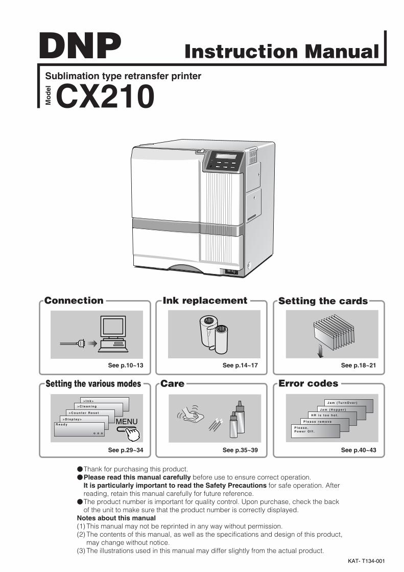
Jam (TurnOver) Jam (Hopper) HR is too hot. Please remove MEDIA FILM Please, Power Off. >Ink> >Cleaning >Counter Reset >Display> Ready MENU Instruction Manual Sublimation type retransfer printer Model Error codes Setting the cards Care Setting the various modes Ink replacement Connection *** CX210 KAT- T134-001 DNP See p.10~13 See p.14~17 See p.18~21 See p.29~34 See p.35~39 See p.40~43 Thank for purchasing this product. Please read this manual carefully before use to ensure correct operation. It is particularly important to read the Safety Precautions for safe operation. After reading, retain this manual carefully for future reference. The product number is important for quality control. Upon purchase, check the back of the unit to make sure that the product number is correctly displayed. Notes about this manual (1) This manual may not be reprinted in any way without permission. (2) The contents of this manual, as well as the specifications and design of this product, may change without notice. (3) The illustrations used in this manual may differ slightly from the actual product.
Transcript of DNP Instruction Manual CX210 - Javelin and Dai Nippon …€¦ · · 2007-09-06>Counter Reset...
J a m ( Tu r n O v e r )
J a m ( H o p p e r )
H R i s t o o h o t .
P l e a s e r e m o v eM E D I A F I L M
P l e a s e ,P o w e r O f f .
> I n k >
> C l e a n i n g
> C o u n t e r R e s e t
> D i s p l a y >
R e a d y MENU
Instruction ManualSublimation type retransfer printer
Mo
del
Error codes
Setting the cards
CareSetting the various modes
Ink replacementConnection
* * *
CX210
KAT- T134-001
DNP
See p.10~13 See p.14~17 See p.18~21
See p.29~34 See p.35~39 See p.40~43
�Thank for purchasing this product.�Please read this manual carefully before use to ensure correct operation.
It is particularly important to read the Safety Precautions for safe operation. Afterreading, retain this manual carefully for future reference.
�The product number is important for quality control. Upon purchase, check the backof the unit to make sure that the product number is correctly displayed.
Notes about this manual(1) This manual may not be reprinted in any way without permission.(2) The contents of this manual, as well as the specifications and design of this product,
may change without notice.(3) The illustrations used in this manual may differ slightly from the actual product.
2
Declaration of Conformity
Model Number: CX210yyyyy(y=A-Z,0-9 or blank)
Product name: Card Printer
We herewith declare that the above mentioned product complies with the following council
directives and harmonized standards.
Council Directives: 89/336/EEC relating to electromagnetic compatibility.
73/23/EEC relating to electrical equipment designed for use within
certain voltage limits.
Harmonized Standards: EN55022:1998+A1 2000 Class A
EN55024:1998
EN61000-3-2:1995+A1:1998+A2:1998+A14:2000
EN61000-3-3:1995
EN60950:2000
Manufacture:
Victor Data Systems Co., Ltd.
1644, Shimotsuruma, Yamato-shi, Kanagawa-ken, 242-8514, Japan
Importer and distributer:
DAI NIPPON PRINTING CO., LTD.
1-1 Ichigaya-kagacho, 1-chome Shinjuku-ku, Tokyo 162-8001 Japan
Phone: +81-3-3266-3344 Facsimile: +81-3-3266-2732
Year to begin affixing CE Marking: 2002
Yamato-shi, March.21.2002
Place, Date Tateki Hisanaga General Manager-Quality Control
Victor Data Systems Co., Ltd.
3
For Europe only
Warning
This is a Class A product. In a domestic environment this product may cause radio interference in which
case the user may be required to take adequate measures.
For USA only
NOTE: This equipment has been tested and found to comply with the limits for a Class A digital device,
pursuant to Part 15 of the FCC Rules. These limits are designed to provide reasonable protection
against harmful interference when the equipment is operated in a commercial environment. This
equipment generates, used, and can radiate radio frequency energy and, if not installed and used
in accordance with the instruction manual, may cause harmful interference to radio
communications.
Operation of this equipment in a residential area is likely to cause harmful interference in which
case the user will be required to correct the interference at his own expense.
CAUTION: Changes or modifications not approved by party responsible for compliance could void user’s
authority to operate the equipment.
Machine Noise
Sound power level: less than 70 dB (A) according to DIN45635 part 19 (EN27779).
The measurements are to be made according to DIN 45635 part 2019 or EN27779, respectively.
4
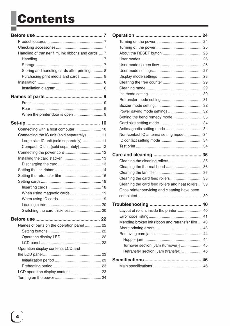
ContentsBefore use .................................................... 7
Product features .................................................... 7
Checking accessories............................................ 7
Handling of transfer film, ink ribbons and cards .... 7
Handling ............................................................. 7
Storage .............................................................. 7
Storing and handling cards after printing ........... 8
Purchasing print media and cards ..................... 8
Installation ............................................................. 8
Installation diagram ............................................ 8
Names of parts ............................................ 9Front ................................................................... 9
Rear ................................................................... 9
When the printer door is open ........................... 9
Set-up ......................................................... 10Connecting with a host computer ........................ 10
Connecting the IC unit (sold separately) ............. 11
Large size IC unit (sold separately) ................. 11
Compact IC unit (sold separately) .................... 12
Connecting the power cord .................................. 12
Installing the card stacker .................................... 13
Discharging the card ........................................ 13
Setting the ink ribbon ........................................... 14
Setting the retransfer film .................................... 16
Setting cards........................................................ 18
Inserting cards ................................................. 18
When using magnetic cards............................. 19
When using IC cards........................................ 19
Loading cards .................................................. 20
Switching the card thickness ............................ 20
Before use .................................................. 22Names of parts on the operation panel ............... 22
Setting buttons ................................................. 22
Operation display LED ..................................... 22
LCD panel ........................................................ 22
Operation display contents LCD and
the LCD panel ...................................................... 23
Initialization period ........................................... 23
Preheating period............................................. 23
LCD operation display content ............................ 23
Turning on the power ........................................... 24
Operation ................................................... 24Turning on the power ........................................... 24
Turning off the power ........................................... 25
About the RESET button ..................................... 25
User modes ......................................................... 26
User mode screen flow ........................................ 26
User mode settings.............................................. 27
Display mode settings ......................................... 28
Clearing the free counter ..................................... 29
Cleaning mode .................................................... 29
Ink mode setting .................................................. 30
Retransfer mode setting ...................................... 31
Buzzer mode setting ............................................ 32
Power saving mode settings ................................ 32
Setting the bend remedy mode ........................... 33
Card size setting mode ........................................ 34
Antimagnetic setting mode .................................. 34
Non-contact IC antenna setting mode ................. 34
IC contact setting mode ....................................... 34
Test print .............................................................. 34
Care and cleaning ..................................... 35Cleaning the cleaning rollers ............................... 35
Cleaning the thermal head .................................. 36
Cleaning the fan filter ........................................... 36
Cleaning the card feed rollers .............................. 38
Cleaning the card feed rollers and heat rollers .... 39
Once printer servicing and cleaning have been
completed ............................................................ 39
Troubleshooting ........................................ 40Layout of rollers inside the printer ....................... 40
Error code listing.................................................. 41
Mending broken ink ribbon and retransfer film .... 43
About printing errors ............................................ 43
Removing card jams ............................................ 44
Hopper jam ...................................................... 44
Turnover section [Jam (turnover)] .................... 45
Retransfer section [Jam (transfer)] ................... 45
Specifications ............................................ 46Main specifications .............................................. 46
5
(to the next page)Notes for safe operationBefore you use
Read these notes on safety thoroughly before operating your printer in order to use the unit properly. Once youstart using the unit, this manual should be put aside the unit, or at a convenient place where you can look up the
manual any time as you need.
WARNING
WARNING CAUTION� If you ignore the warning with this mark, and handle
the unit in a wrong way, death or serious injuries mayoccur.
� If you ignore the caution with this mark, and handlethe unit in a wrong way, injuries or damages toproperties may occur.
� If the abnormal phenomena as listed below areseen, immediately stop operating the unit.Continuing operation may cause a fire or electricshock.
•Smoke or odd smell comes out from the machine.•Water or metal went into the machine.•The unit fell to the floor, or the cabinet was broken.•The power cable is damaged (exposed lead, broken cable,
etc.)If you see these phenomena, turn off the power, pull out thepower plug, and contact your dealer as soon as possible. Donot try to repair it by yourself. It is dangerous.
�Do not remove the screws, or disassemble oralter the machine.
•High-voltage components are contained in the unit.Touching these areas may result in an electric shock.
•Ask your dealer if you want your printer inspected orrepaired.
•Do not remove the external covers of the machine. You mayget an electric shock.
�Do not work on the power cable, or giveexcessive force on it. Do not put heavy objectssuch as furniture on the cable.
•The cable may be damaged, causing a fire or electricshock.
•When you find a defect on the power cable, such asexposed lead, stop using the unit, and consult your dealer.
�Do not use the machine with the power pluginserted incompletely.
•The machine generates heat due to incomplete contact,causing a fire or electric shock.
•Do not put many cords on a single plug socket. The powercords also heats up.
�Do not use the machine with dusts piled on thepower plug. Do not put a metallic materialadjacent to the power plug.
•Dusts and metal are conductive, causing a fire or electricshock.
•Pull out the power plug from the outlet every six months,and clean the dusts piled on the legs and body of the plug.
�Do not use a line voltage other than instructed.•Using a line voltage or power supply which is not specified
may cause a fire or electric shock.
�Do not put foreign materials from the openings ofthe machine (e.g., vents, card slots, cassette inlet,etc.)
•Metals, flammable things, and other foreign materials maycause a fire or electric shock if entering into the machine.
• If these things went into the machine, immediately turn offthe power, pull out the power plug, and ask your dealer torepair. Do not try to repair it by yourself. It is dangerous.
�Do not put a container with liquid in it, or smallmetal ornaments and the like on the machine.
•The liquid or metal entering into the machine acts as aconductor, causing a fire or electric shock.
• If liquid or metal went into the machine, immediately turn offthe power, pull out the power plug, and ask your dealer torepair. Do not try to repair it by yourself. It is dangerous.
�Do not place the machine on a rickety table orslanting places.
•The machine may fall out of the table or fall over, which maydamage the machine or injure you.
• If the machine is damaged by falling or turnover,immediately turn off the power, pull out the power plug, andask your dealer to repair. Do not try to repair it by yourself. Itis dangerous.
�Do not wet the machine with water.•Using the machine at a place where water splashes on the
machine, or wetting the machine with water (applying,throwing, or spilling water over the machine) may cause afire or electric shock.
• If water entered into the machine, immediately turn off thepower, pull out the power plug, and ask your dealer torepair. Do not try to repair it by yourself. It is dangerous.
�Do not touch the machine with wet hands.•Touching the machine with wet hands may cause an
electric shock.
�Do not touch the power plug during electricalstorms.
•Lightning may cause an electric shock.
6
Notes for safe operation (continued)
�Pull out the power plug before cleaning themachine.
•This is for preventing electric shocks.
�Pull out the power plug when you won’t use themachine for a prolonged period of time to assuresafety.
•Remove the power plug from the outlet for safety when youwon’t use the machine for a long time.
�Do not move the machine with the power cableand other electric cables connected.
•The cables may be damaged while being moved, whichmay cause a fire or electric shock.
•You may stumble over the cable and get injured.
�Do not move the machine with objects placed onit.
•They may fall on you and hurt you.
�Do not put heavy objects on the machine.•They may fall on you and hurt you.
�Do not block the vents.•Heat generated inside the machine cannot escape, which
may cause a fire.
�Be sure to work with two persons when youunpack, move or lift the machine.
• If you work alone, you may be injured by the fallen machineor hurt your back by lifting a heavy machine by yourself.
� Inspection•Ask you dealer or a qualified person to inspect the machine,
typically once every two to three years. Operating themachine with dusts piling on the components for aprolonged period of time may cause a fire or a malfunctionof the machine. It will be particularly effective to inspect themachine before wet rainy season. Consult your dealer onthe costs of inspection.
�Do not put the machine at a place where it will bewet with steam (e.g., from a humidifier), or at aexcessively humid or dusty place.
•The oil, water and dusts act as conductors, which maycause a fire or electric shock.
CAUTION
�Ground the machine with the attached electriccord when connecting it to the utility outlet.
•Using a cord other than the one supplied for grounding maycause an electric shock when the machine fails.
�Do not put your head or yourself into thepackaging bag.
•Do not play with the packaging bag. You may suffocateyourself.
•Give close attention to small children who may want to playwith the packaging bag.
�Do not use the machine while it has a fault.•Do not use the machine while it has a fault, as this may
cause a fire or electric shock.• Immediately turn off the power, pull out the power plug, and
ask your dealer to repair. Do not try to repair it by yourself. Itis dangerous.
�Do not put the machine at a place where itbecomes excessively hot.
•The surface and internal components may deteriorate. Alsothere is a danger of a fire. Special care should be taken forexposure to direct sunlight or a heater adjacent to themachine.
�Hold the body of the power plug when pulling itout.
•Do not pull out the plug by holding the cable. The cablemay be broken or damaged which may in turn cause a fireor electric shock.
�Do not touch the power plug with a wet hand•You may get an electric shock.
�Do not lay the power cable near the heatingequipment.
•The covering of the cable will melt due to heat from suchequipment, which may cause a fire or electric shock.
�The heat rollers and adjacent areas become hotduring operation.
•Be careful not to touch the heat rollers and adjacent areaswhen replacing the ink ribbon or retransfer film, or removejammed cards.
•Wait until the heat rollers get cooled down to prevent burns.
�Be careful of jamming your hand or fingers in thecard tray, card bracket on the hopper, or printerdoor.
•Replace the ink ribbon or retransfer film, or remove jammedcards with care not to jam your hand or fingers in themechanism, which may cause an injury.
�Do not use a power cable other than the specifiedcable for connection.
• If you use an unspecified power cable for connection orextension, heat may accumulate in the cable, causing a fire.
7
(to the next page)Before useProduct features
�This card printer allows printing of high-quality, full-color images equivalent to photographic quality ontostandard size (ISO 7810 compliance) plastic cardsusing sublimation type transfer printing.
�Use of sublimation type retransfer printing enablesprinting of cards other than those made of PVC andnon-contact IC cards, etc. with uneven surfaces thatwere previously difficult to print directly.
�Printing with no margins on all sides is possible.
�The host interface utilizes SCSI (asynchronous)mode. The unit has a built-in SCSI bus terminator.
Checking accessories
Please check for any missing accessories whenopening the box.
�Power cord: AC100V type: · · · · · · · · · · · 1 unit(For Japan)AC120V type: · · · · · · · · · · · 1 unit(For North America)AC220V-240V cord: · · · · · · · 1 unit(For Europe)
* The detached power cords vary according to modeland country of purchase.
�Cleaning card : 1 unit
�Card stacker : 1 unit
� Instruction manual : English · · · · · · · · · 1 unitJapanese · · · · · · · 1 unit
� Ink ribon cassette : 1 unit
�Retransfer film : 1 unitcassette
�Ferrite core : 2 units(Standard model : 1 unit,built-in IC encoder model : 2units)
�Binder(for securing : 4 unitsthe ferrite core) (Standard model : 2 units,
built-in IC encoder model : 4units)
�Jog lever (inside the card tray): 1 unit
Some card materials may not be suitable for printing. Consultyour dealer regarding the materials to be used andspecifications required before purchase.
Handling of transfer film,ink ribbons and cards
Handling
Take note of the following points when handling printmedia (retransfer film and ink ribbons) and cards.
• Use of bent or damaged cards may result in cardfeed error.
• Do not touch the print media or the printed surfaceof cards directly with the hands as this may causeblurring of the print.
• Foreign materials on the printing area may result inmisprints. Always load the print media and cards ina clean environment.
• Static build-up in the print media or cards cancause errors. To avoid causing static electricity, donot rub cards together.
• When replacing or replenishing print media orcards that have been stored at low temperatures, letthe print media or cards sit for at least one hour atthe same temperature as location where the printeris to be used before use. Using print media or cardsas they are may cause condensation and result inmalfunction or print errors.
Storage
The storage condition of the print media (retransfer filmand ink ribbons) and cards may have a stronginfluence on the print quality. Select a storage locationthat fits the following criteria:
Storage environmentStorage temperature : 5°C to 25°CStorage environment relative humidity : 40% to 60%
Storage locationTo avoid deterioration of the print media, do not storein the following locations:
• Locations exposed to direct sunlight• Locations with high humidity• Locations near organic solvents or diazo copiers.
Storage periodUse within one year.
8
Before use (continued)
Storing and handling cards after printing
Avoid storing the cards in locations exposed to directsunlight or with high humidity.Furthermore, avoid contact with the followingchemicals and stationery, as they can causediscoloration or fading of the cards:
• Organic solvents such as alcohol, film cleaner,diazo copies, etc.
• Soft vinyl chlorides, document cases, pass holders,erasers, etc.
• Hair-dressing products and cosmetics, etc.
Purchasing print media and cards
Contact your dealer regarding the purchase of printmedia (retransfer film and ink ribbons) and cards.Always use the products specified below.
Print mediaUse only the ink ribbons and retransfer film specifiedfor this unit. For the names of these products refer to“Main Specifications” on p. 46 of this manual.
We can accept no liability for anyproblems arising as a result of the use of media usingmaterials other than those specified.
Card materialISO/IEC 7810 type ID1 (dimensions) :
equivalent productISO/IEC 7811-2 (Magnetic stripe) :
equivalent productISO/IEC 7816 (IC card) : equivalent product
The materials of some cards may not be suitable forprinting. Consult your dealer regarding the materials tobe used and specifications required before purchase.
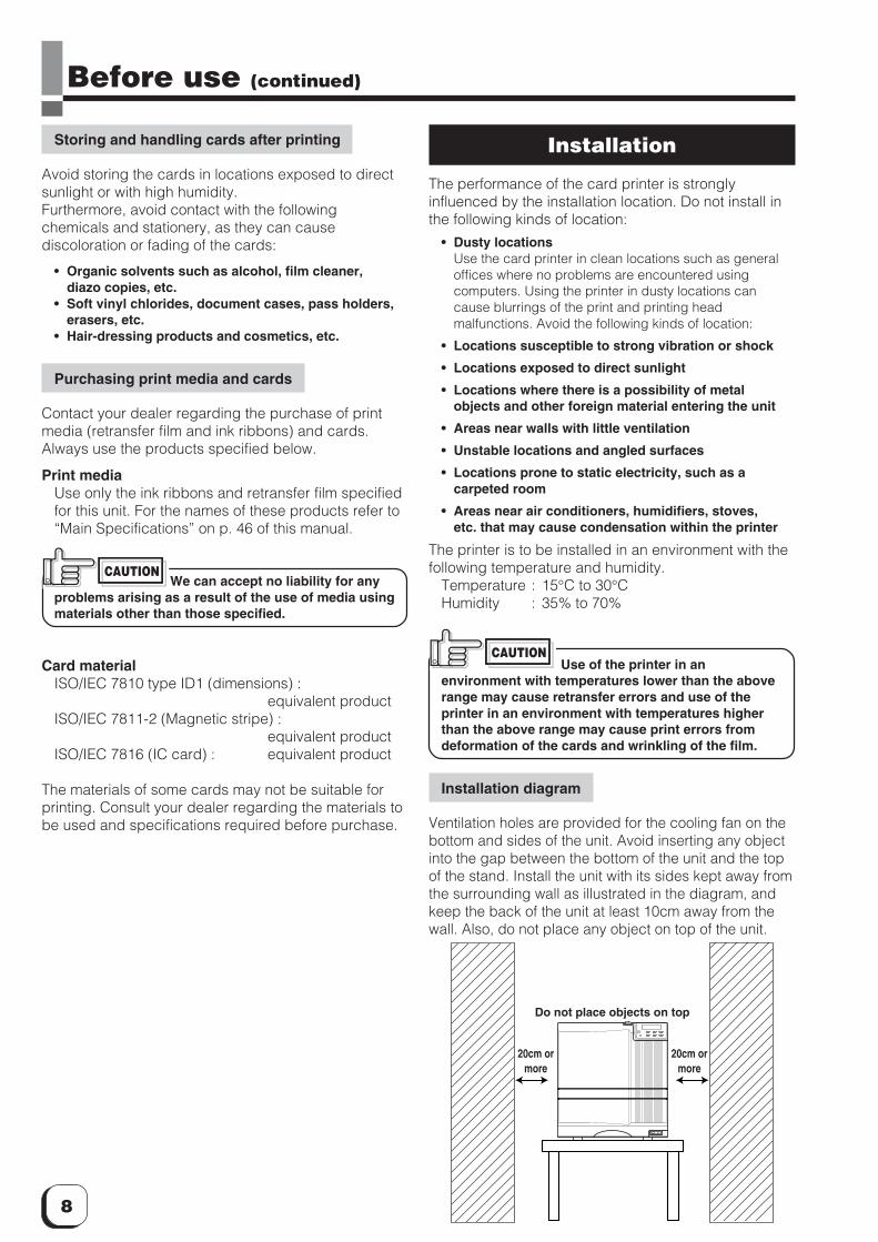
Do not place objects on top
20cm ormore
20cm ormore
Installation
The performance of the card printer is stronglyinfluenced by the installation location. Do not install inthe following kinds of location:
• Dusty locationsUse the card printer in clean locations such as generaloffices where no problems are encountered usingcomputers. Using the printer in dusty locations cancause blurrings of the print and printing headmalfunctions. Avoid the following kinds of location:
• Locations susceptible to strong vibration or shock
• Locations exposed to direct sunlight
• Locations where there is a possibility of metalobjects and other foreign material entering the unit
• Areas near walls with little ventilation
• Unstable locations and angled surfaces
• Locations prone to static electricity, such as acarpeted room
• Areas near air conditioners, humidifiers, stoves,etc. that may cause condensation within the printer
The printer is to be installed in an environment with thefollowing temperature and humidity.
Temperature : 15°C to 30°CHumidity : 35% to 70%
Use of the printer in anenvironment with temperatures lower than the aboverange may cause retransfer errors and use of theprinter in an environment with temperatures higherthan the above range may cause print errors fromdeformation of the cards and wrinkling of the film.
Installation diagram
Ventilation holes are provided for the cooling fan on thebottom and sides of the unit. Avoid inserting any objectinto the gap between the bottom of the unit and the topof the stand. Install the unit with its sides kept away fromthe surrounding wall as illustrated in the diagram, andkeep the back of the unit at least 10cm away from thewall. Also, do not place any object on top of the unit.
CAUTION
CAUTION
9
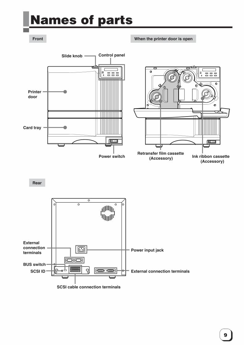
Names of partsFront When the printer door is open
Slide knob Control panel
Printerdoor
Card tray
Power switchRetransfer film cassette
(Accessory) Ink ribbon cassette(Accessory)
Rear
Externalconnectionterminals
Power input jack
External connection terminals
SCSI cable connection terminals
SCSI ID
BUS switch
10
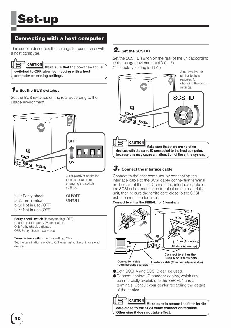
Set-upConnecting with a host computer
This section describes the settings for connection witha host computer.
Make sure that the power switch isswitched to OFF when connecting with a hostcomputer or making settings.
1. Set the BUS switches.
Set the BUS switches on the rear according to theusage environment.
bit1: Parity check ON/OFFbit2: Termination ON/OFFbit3: Not in use (OFF)bit4: Not in use (OFF)
Parity check switch (factory setting: OFF)Used to set the parity switch feature.ON: Parity check activatedOFF: Parity check inactivated
Termination switch (factory setting: ON)Set the termination switch to ON when using the unit as a enddevice.
CAUTION
2. Set the SCSI ID.
Set the SCSI ID switch on the rear of the unit accordingto the usage environment (ID 0 – 7).(The factory setting is ID 0.)
Make sure that there are no otherdevices with the same ID connected to the host computer,because this may cause a malfunction of the entire system.
3. Connect the interface cable.
Connect to the host computer by connecting theinterface cable to the SCSI cable connection terminalon the rear of the unit. Connect the interface cable tothe SCSI cable connection terminal on the rear of theunit, then secure the ferrite core close to the SCSIcable connection terminal.
�Both SCSI A and SCSI B can be used.�Connect contact-IC encoder cables, which are
commercially available to the SERIAL1 and 2terminals. Consult your dealer regarding the detailsof the cables.
Make sure to secure the filter ferritecore close to the SCSI cable connection terminal.Otherwise it does not take effect.
CAUTION
CAUTION
A screwdriver or similartools is required forchanging the switchsettings.
1 2 3 4
ON
OFF
A screwdriver orsimilar tools isrequired forchanging the switchsettings.
0
3 6
1
4
72
5
SCSI ID
Connect to either the SERIAL1 or 2 terminals
Core (Accessory)
Binder (Accessory)
Connect to either theSCSI A or B terminals
Connection cable(Commercially available)
Interface cable (Commercially available)
11
(to the next page)
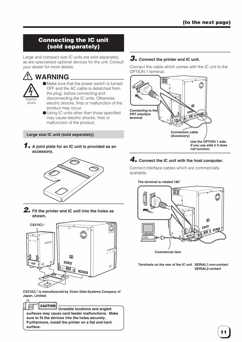
Use the OPTION 1 side.If you use side 2 it doesnot function.
Electricshock
Connecting to thePRT interfaceterminal
Connection cable(Accessory)
Commercial item
Terminals on the rear of the IC unit SERIAL1:non-contactSERIAL2:contact
The terminal is rotated 180°
CX21ICL*
3. Connect the printer and IC unit.
Connect the cable which comes with the IC unit to theOPTION 1 terminal.
4. Connect the IC unit with the host computer.
Connect interface cables which are commerciallyavailable.
Connecting the IC unit(sold separately)
Large and compact size IC units are sold separately,as are specialized optional devices for the unit. Consultyour dealer for more details.
WARNING�Make sure that the power switch is turned
OFF and the AC cable is detatched fromthe plug, before connecting anddisconnecting the IC units. Otherwiseelectric shocks, fires or malfunction of theproduct may occur.
�Using IC units other than those specifiedmay cause electric shocks, fires ormalfunction of the product.
Large size IC unit (sold separately)
1. A joint plate for an IC unit is provided as anaccessory.
2. Fit the printer and IC unit into the holes asshown.
CX21ICL* is manufactured by Victor Data Systems Company ofJapan, Limited.
Unstable locations and angledsurfaces may cause card feeder malfunctions. Makesure to fit the devices into the holes securely.Furthermore, install the printer on a flat and hardsurface.
CAUTION
12
Set-up (continued)
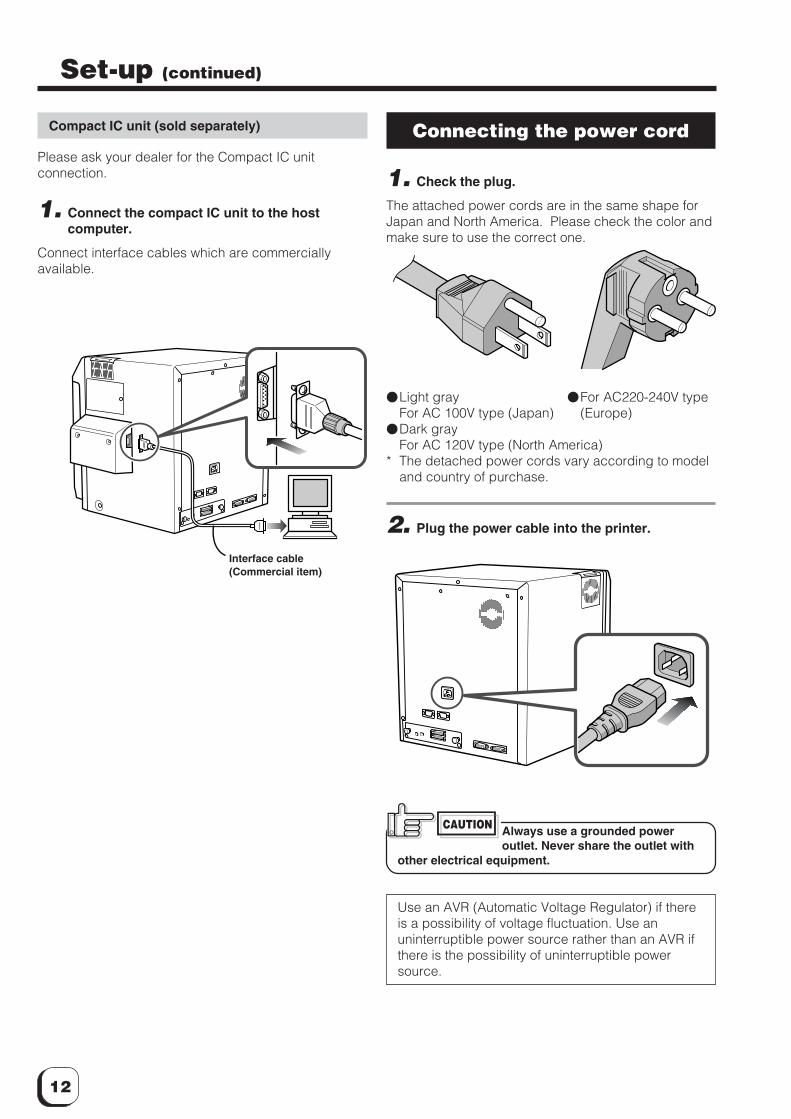
Compact IC unit (sold separately)
Please ask your dealer for the Compact IC unitconnection.
1. Connect the compact IC unit to the hostcomputer.
Connect interface cables which are commerciallyavailable.
Connecting the power cord
1. Check the plug.
The attached power cords are in the same shape forJapan and North America. Please check the color andmake sure to use the correct one.
�Light gray �For AC220-240V typeFor AC 100V type (Japan) (Europe)
�Dark grayFor AC 120V type (North America)
* The detached power cords vary according to modeland country of purchase.
2. Plug the power cable into the printer.
Always use a grounded poweroutlet. Never share the outlet with
other electrical equipment.
Use an AVR (Automatic Voltage Regulator) if thereis a possibility of voltage fluctuation. Use anuninterruptible power source rather than an AVR ifthere is the possibility of uninterruptible powersource.
Interface cable(Commercial item)
CAUTION
13
(to the next page)
Card dischargeslot
Claw
Card stacker(accessory)
Card stackerreceptacle
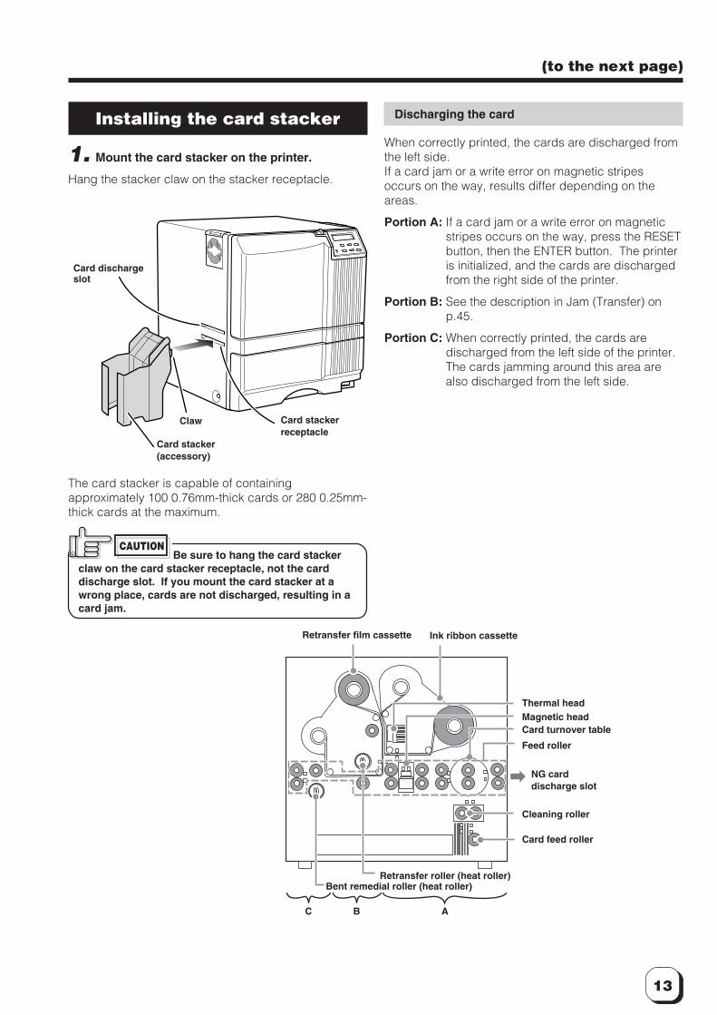
Installing the card stacker
1. Mount the card stacker on the printer.
Hang the stacker claw on the stacker receptacle.
The card stacker is capable of containingapproximately 100 0.76mm-thick cards or 280 0.25mm-thick cards at the maximum.
Be sure to hang the card stackerclaw on the card stacker receptacle, not the carddischarge slot. If you mount the card stacker at awrong place, cards are not discharged, resulting in acard jam.
CAUTION
Discharging the card
When correctly printed, the cards are discharged fromthe left side.If a card jam or a write error on magnetic stripesoccurs on the way, results differ depending on theareas.
Portion A: If a card jam or a write error on magneticstripes occurs on the way, press the RESETbutton, then the ENTER button. The printeris initialized, and the cards are dischargedfrom the right side of the printer.
Portion B: See the description in Jam (Transfer) onp.45.
Portion C: When correctly printed, the cards aredischarged from the left side of the printer.The cards jamming around this area arealso discharged from the left side.
C B A
Retransfer film cassette Ink ribbon cassette
Thermal headMagnetic headCard turnover table
Feed roller
NG carddischarge slot
Cleaning roller
Card feed roller
Retransfer roller (heat roller)Bent remedial roller (heat roller)
14
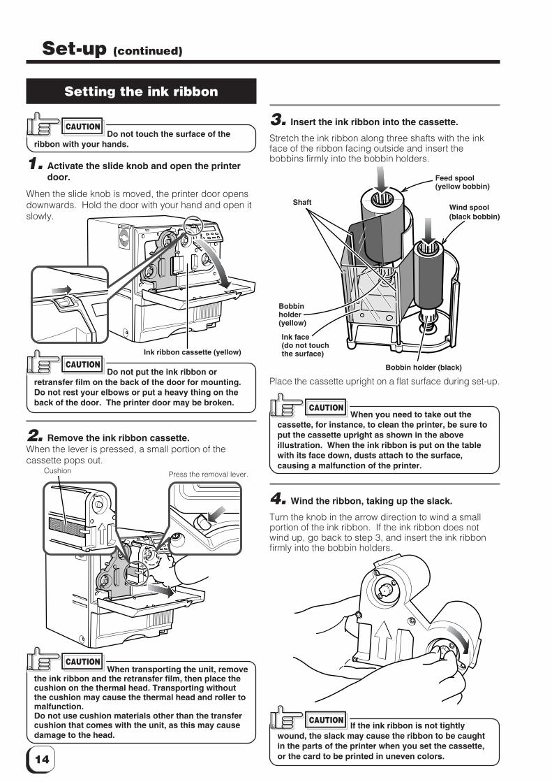
3. Insert the ink ribbon into the cassette.
Stretch the ink ribbon along three shafts with the inkface of the ribbon facing outside and insert thebobbins firmly into the bobbin holders.
Place the cassette upright on a flat surface during set-up.
When you need to take out thecassette, for instance, to clean the printer, be sure toput the cassette upright as shown in the aboveillustration. When the ink ribbon is put on the tablewith its face down, dusts attach to the surface,causing a malfunction of the printer.
4. Wind the ribbon, taking up the slack.
Turn the knob in the arrow direction to wind a smallportion of the ink ribbon. If the ink ribbon does notwind up, go back to step 3, and insert the ink ribbonfirmly into the bobbin holders.
If the ink ribbon is not tightlywound, the slack may cause the ribbon to be caughtin the parts of the printer when you set the cassette,or the card to be printed in uneven colors.
Setting the ink ribbon
Do not touch the surface of theribbon with your hands.
1. Activate the slide knob and open the printerdoor.
When the slide knob is moved, the printer door opensdownwards. Hold the door with your hand and open itslowly.
Do not put the ink ribbon orretransfer film on the back of the door for mounting.Do not rest your elbows or put a heavy thing on theback of the door. The printer door may be broken.
2. Remove the ink ribbon cassette.When the lever is pressed, a small portion of thecassette pops out.
When transporting the unit, removethe ink ribbon and the retransfer film, then place thecushion on the thermal head. Transporting withoutthe cushion may cause the thermal head and roller tomalfunction.Do not use cushion materials other than the transfercushion that comes with the unit, as this may causedamage to the head.
CAUTION
Set-up (continued)
CAUTION
Press the removal lever.
Ink ribbon cassette (yellow)
CAUTION
Shaft
Bobbinholder(yellow)
Ink face(do not touchthe surface)
Bobbin holder (black)
Wind spool(black bobbin)
Feed spool(yellow bobbin)
CAUTION
CAUTION
Cushion
15
(to the next page)
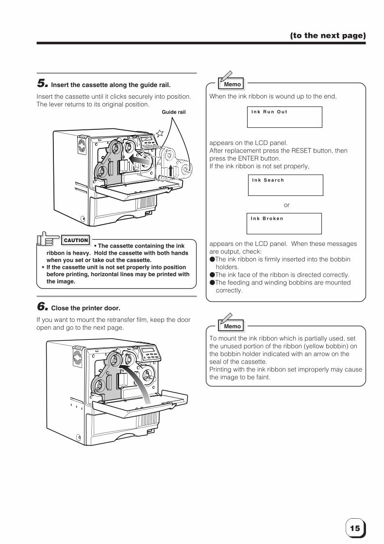
5. Insert the cassette along the guide rail.
Insert the cassette until it clicks securely into position.The lever returns to its original position.
• The cassette containing the inkribbon is heavy. Hold the cassette with both handswhen you set or take out the cassette.
• If the cassette unit is not set properly into positionbefore printing, horizontal lines may be printed withthe image.
6. Close the printer door.
If you want to mount the retransfer film, keep the dooropen and go to the next page.
Guide rail
CAUTION
I n k R u n O u t
I n k S e a r c h
I n k B r o k e n
Memo
When the ink ribbon is wound up to the end,
appears on the LCD panel.After replacement press the RESET button, thenpress the ENTER button.If the ink ribbon is not set properly,
or
appears on the LCD panel. When these messagesare output, check:�The ink ribbon is firmly inserted into the bobbin
holders.�The ink face of the ribbon is directed correctly.�The feeding and winding bobbins are mounted
correctly.
Memo
To mount the ink ribbon which is partially used, setthe unused portion of the ribbon (yellow bobbin) onthe bobbin holder indicated with an arrow on theseal of the cassette.Printing with the ink ribbon set improperly may causethe image to be faint.
16
Set-up (continued)
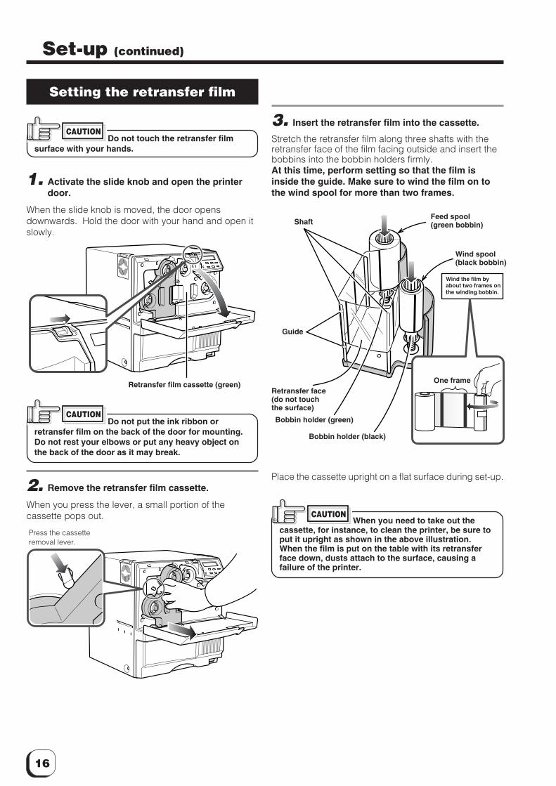
Setting the retransfer film
Do not touch the retransfer filmsurface with your hands.
1. Activate the slide knob and open the printerdoor.
When the slide knob is moved, the door opensdownwards. Hold the door with your hand and open itslowly.
Do not put the ink ribbon orretransfer film on the back of the door for mounting.Do not rest your elbows or put any heavy object onthe back of the door as it may break.
2. Remove the retransfer film cassette.
When you press the lever, a small portion of thecassette pops out.
CAUTION
Press the cassetteremoval lever.
3. Insert the retransfer film into the cassette.
Stretch the retransfer film along three shafts with theretransfer face of the film facing outside and insert thebobbins into the bobbin holders firmly.At this time, perform setting so that the film isinside the guide. Make sure to wind the film on tothe wind spool for more than two frames.
Place the cassette upright on a flat surface during set-up.
When you need to take out thecassette, for instance, to clean the printer, be sure toput it upright as shown in the above illustration.When the film is put on the table with its retransferface down, dusts attach to the surface, causing afailure of the printer.
Retransfer film cassette (green)
CAUTION
CAUTION
Shaft
Bobbin holder (green)
Retransfer face(do not touchthe surface)
Feed spool(green bobbin)
Wind spool(black bobbin)
Bobbin holder (black)
Wind the film byabout two frames onthe winding bobbin.
One frame
Guide
17
(to the next page)
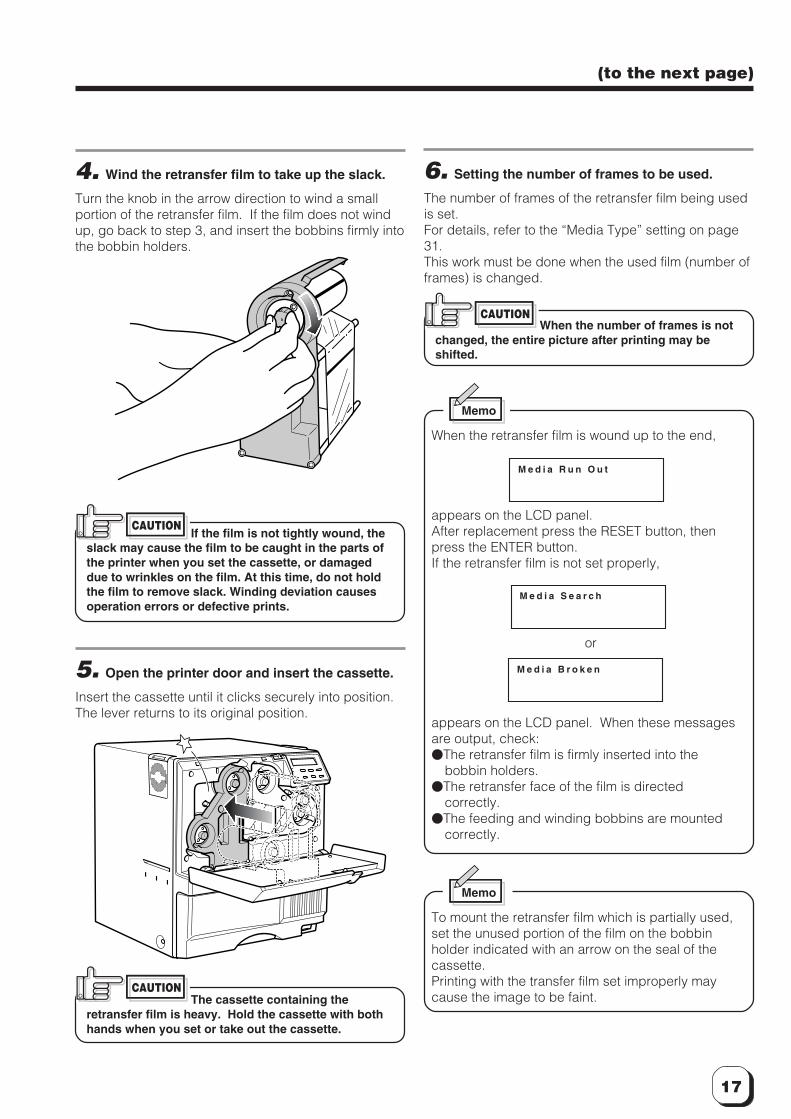
4. Wind the retransfer film to take up the slack.
Turn the knob in the arrow direction to wind a smallportion of the retransfer film. If the film does not windup, go back to step 3, and insert the bobbins firmly intothe bobbin holders.
If the film is not tightly wound, theslack may cause the film to be caught in the parts ofthe printer when you set the cassette, or damageddue to wrinkles on the film. At this time, do not holdthe film to remove slack. Winding deviation causesoperation errors or defective prints.
5. Open the printer door and insert the cassette.
Insert the cassette until it clicks securely into position.The lever returns to its original position.
The cassette containing theretransfer film is heavy. Hold the cassette with bothhands when you set or take out the cassette.
CAUTION
6. Setting the number of frames to be used.
The number of frames of the retransfer film being usedis set.For details, refer to the “Media Type” setting on page31.This work must be done when the used film (number offrames) is changed.
When the number of frames is notchanged, the entire picture after printing may beshifted.
CAUTION
M e d i a R u n O u t
M e d i a S e a r c h
M e d i a B r o k e n
Memo
When the retransfer film is wound up to the end,
appears on the LCD panel.After replacement press the RESET button, thenpress the ENTER button.If the retransfer film is not set properly,
or
appears on the LCD panel. When these messagesare output, check:�The retransfer film is firmly inserted into the
bobbin holders.�The retransfer face of the film is directed
correctly.�The feeding and winding bobbins are mounted
correctly.
Memo
To mount the retransfer film which is partially used,set the unused portion of the film on the bobbinholder indicated with an arrow on the seal of thecassette.Printing with the transfer film set improperly maycause the image to be faint.
CAUTION
18
Set-up (continued)
Setting cards
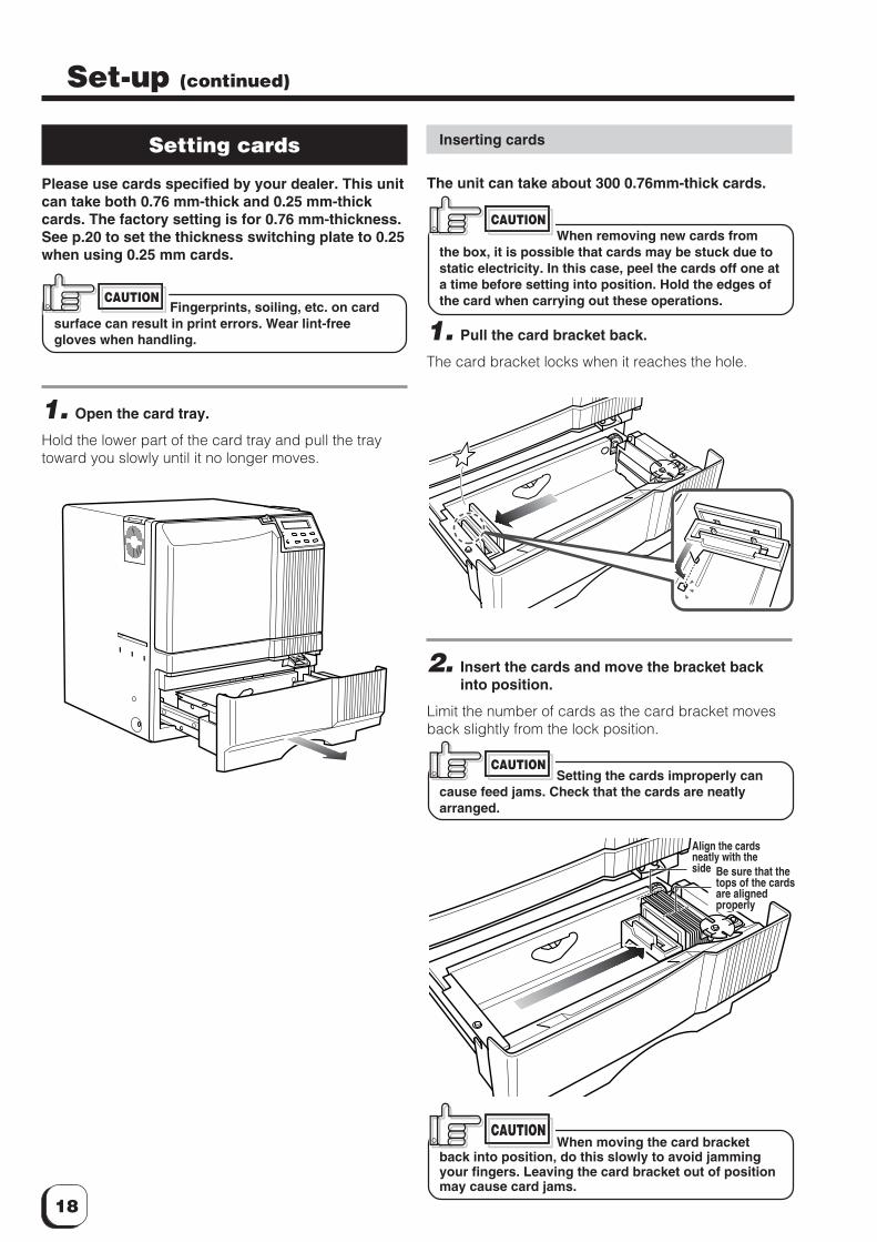
Please use cards specified by your dealer. This unitcan take both 0.76 mm-thick and 0.25 mm-thickcards. The factory setting is for 0.76 mm-thickness.See p.20 to set the thickness switching plate to 0.25when using 0.25 mm cards.
Fingerprints, soiling, etc. on cardsurface can result in print errors. Wear lint-freegloves when handling.
1. Open the card tray.
Hold the lower part of the card tray and pull the traytoward you slowly until it no longer moves.
CAUTION
Inserting cards
The unit can take about 300 0.76mm-thick cards.
When removing new cards fromthe box, it is possible that cards may be stuck due tostatic electricity. In this case, peel the cards off one ata time before setting into position. Hold the edges ofthe card when carrying out these operations.
1. Pull the card bracket back.
The card bracket locks when it reaches the hole.
2. Insert the cards and move the bracket backinto position.
Limit the number of cards as the card bracket movesback slightly from the lock position.
Setting the cards improperly cancause feed jams. Check that the cards are neatlyarranged.
When moving the card bracketback into position, do this slowly to avoid jammingyour fingers. Leaving the card bracket out of positionmay cause card jams.
CAUTION
CAUTION
CAUTION
Align the cardsneatly with theside Be sure that the
tops of the cardsare alignedproperly
19
(to the next page)
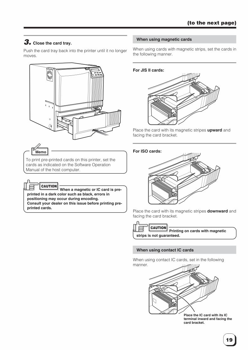
3. Close the card tray.
Push the card tray back into the printer until it no longermoves.
Memo
To print pre-printed cards on this printer, set thecards as indicated on the Software OperationManual of the host computer.
When a magnetic or IC card is pre-printed in a dark color such as black, errors inpositioning may occur during encoding.Consult your dealer on this issue before printing pre-printed cards.
When using magnetic cards
When using cards with magnetic strips, set the cards inthe following manner.
For JIS II cards:
Place the card with its magnetic stripes upward andfacing the card bracket.
For ISO cards:
Place the card with its magnetic stripes downward andfacing the card bracket.
Printing on cards with magneticstrips is not guaranteed.
When using contact IC cards
When using contact IC cards, set in the followingmanner.
CAUTION
Place the IC card with its ICterminal inward and facing thecard bracket.
CAUTION
20
Set-up (continued)
Loading cards
Load cards when the printer’s LCD shows the message“Ready” or “No Card,” etc. and not when printeroperations have stopped due to an error. Cards canalso be loaded when the power supply is not switchedon. If there is a drop in the volume of remaining cards(under 20 cards with a thickness of 0.76mm), theelectronic beep sounds before every feeding.
During printing, if there is a drop in the volume ofremaining cards (under 20 cards with a thicknessof 76mm) an electronic beep sounds.When “Loading” is displayed on the LCD, do notopen the card tray under any circumstances.The unit is currently feeding cards. If a messageother than the one above is displayed, cards canbe loaded even while the unit is printing. However,you are recommended to load cards when the unitis not printing.
To prevent defective printing caused bysuspended printing or vibration as a result ofopening and closing the card tray, load cardswith care.
R e a d y N o C a r d
OR
L o a d i n g
Switching the card thickness
Depending on the material, some 0.25mm thick cardsmay not be suitable for printing. Consult your dealerregarding the materials and specifications of the cardbefore purchasing.
WARNING�Before switching the thickness, turn off the
printer and the devices connecting to theprinter, and take off their power plugs fromthe outlet to prevent an electric shock.
CAUTION�When switching the card thickness, be
careful not to remove the screws exceptthose instructed. Removing uninstructedscrews may cause injuries or amalfunction of the printer.
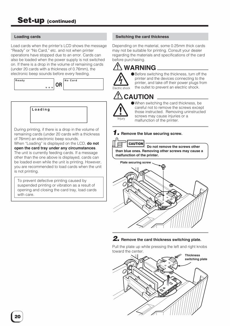
1. Remove the blue securing screw.
Do not remove the screws otherthan blue ones. Removing other screws may cause amalfunction of the printer.
2. Remove the card thickness switching plate.
Pull the plate up while pressing the left and right knobstoward the center.
Injury
Electric shock
CAUTION
Plate securing screw
0.250.76
Thicknessswitching plate
0.76 0.25
21
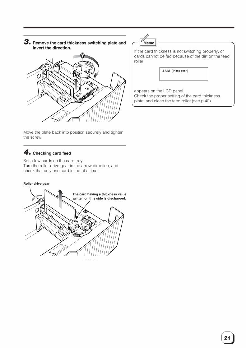
3. Remove the card thickness switching plate andinvert the direction.
Move the plate back into position securely and tightenthe screw.
4. Checking card feed
Set a few cards on the card tray.Turn the roller drive gear in the arrow direction, andcheck that only one card is fed at a time.
0.25 0.76
0.760.25
Roller drive gear
The card having a thickness valuewritten on this side is discharged.
Memo
If the card thickness is not switching properly, orcards cannot be fed because of the dirt on the feedroller,
appears on the LCD panel.Check the proper setting of the card thicknessplate, and clean the feed roller (see p.40).
J A M ( H o p p e r )
22
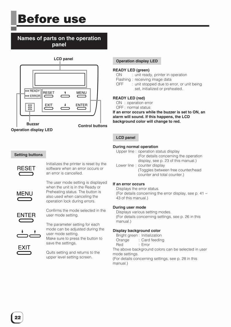
Before useNames of parts on the operation
panel
Setting buttons
Initializes the printer is reset by thesoftware when an error occurs oran error is cancelled.
The user mode setting is displayedwhen the unit is in the Ready orPreheating status. The button isalso used when canceling theoperation lock during errors.
Confirms the mode selected in theuser mode setting.
The parameter setting for eachmode can be adjusted during theuser mode setting.Make sure to press the button tosave the settings.
Quits setting and returns to theupper level setting screen.
RESET
EXIT
MENU
ENTER
READY
ERROR
LCD panel
Operation display LEDControl buttons
ENTER
EXIT
MENU
RESET
Operation display LED
READY LED (green)ON : unit ready, printer in operationFlashing : receiving image dataOFF : unit stopped due to error, or unit being
set, initialized or preheated.
READY LED (red)ON : operation errorOFF : normal status
If an error occurs while the buzzer is set to ON, analarm will sound. If this happens, the LCDbackground color will change to red.
LCD panel
During normal operationUpper line : operation status display
(For details concerning the operationdisplay, see p. 23 of this manual.)
Lower line : counter display(Toggles between free counter/headcounter and total counter.)
If an error occursDisplays the error status.(For details concerning the error display, see p. 41 ~43 of this manual.)
During user modeDisplays various setting modes.(For details concerning settings, see p. 26 in thismanual.)
Display background colorBright green : InitializationOrange : Card feedingRed : Error
The above background colors can be selected in usermode settings.(For details concerning settings, see p. 28 in thismanual.)
Buzzar
23
(to the next page)
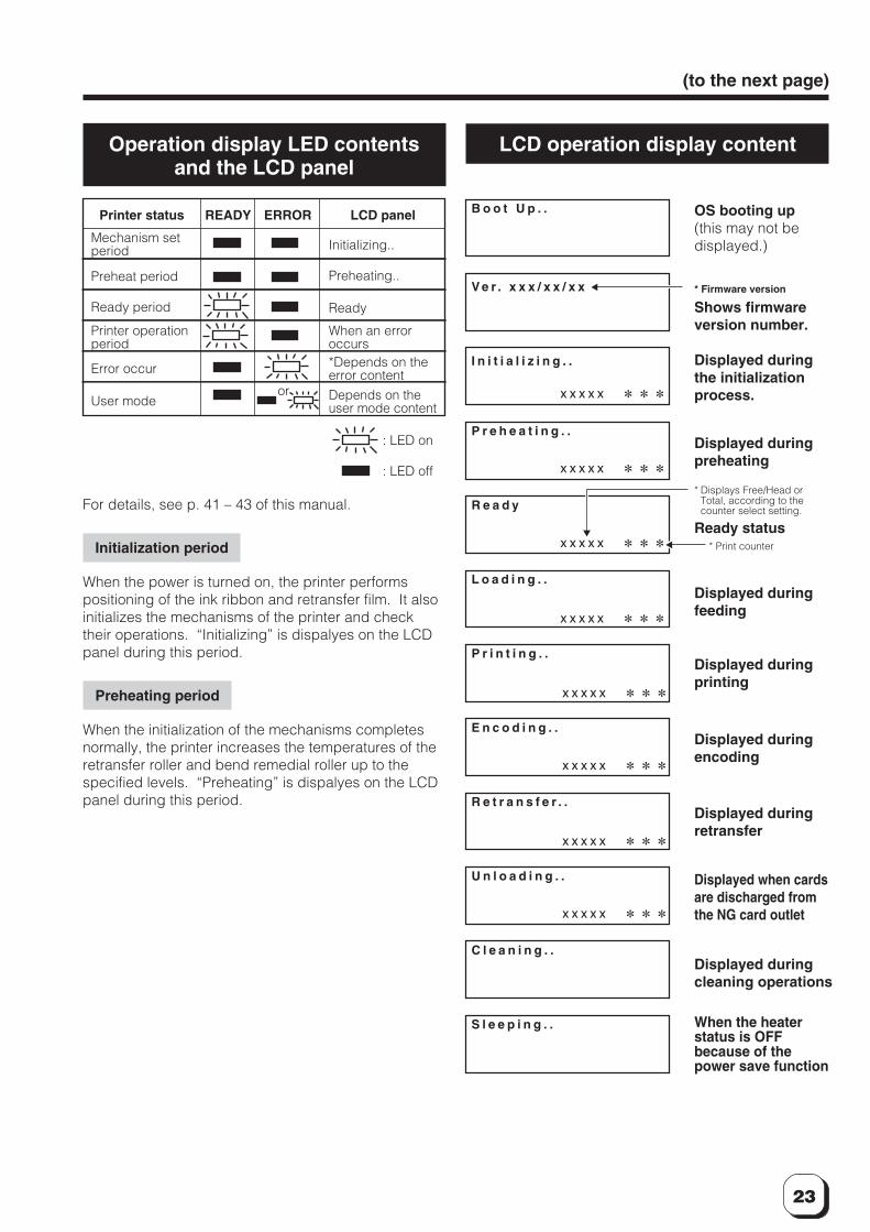
Operation display LED contentsand the LCD panel
For details, see p. 41 – 43 of this manual.
Initialization period
When the power is turned on, the printer performspositioning of the ink ribbon and retransfer film. It alsoinitializes the mechanisms of the printer and checktheir operations. “Initializing” is dispalyes on the LCDpanel during this period.
Preheating period
When the initialization of the mechanisms completesnormally, the printer increases the temperatures of theretransfer roller and bend remedial roller up to thespecified levels. “Preheating” is dispalyes on the LCDpanel during this period.
LCD operation display content
Printer status
Mechanism setperiod
Preheat period
Ready period
Printer operationperiod
Error occur
User mode
READY ERROR LCD panel
Initializing..
Preheating..
Ready
When an erroroccurs*Depends on theerror content
Depends on theuser mode content
or
: LED on
: LED off
I n i t i a l i z i n g . .
P r e h e a t i n g . .
L o a d i n g . .
P r i n t i n g . .
E n c o d i n g . .
R e t r a n s f e r . .
U n l o a d i n g . .
C l e a n i n g . .
S l e e p i n g . .
R e a d y
B o o t U p . .
V e r . x x x / x x / x x
x x x x x
x x x x x
x x x x x
x x x x x
x x x x x
x x x x x
x x x x x
x x x x x
OS booting up(this may not bedisplayed.)
* Firmware version
Shows firmwareversion number.
Displayed duringthe initializationprocess.
Displayed duringpreheating
* Displays Free/Head orTotal, according to thecounter select setting.
Displayed duringfeeding
Ready status* Print counter
Displayed duringprinting
Displayed duringencoding
Displayed duringretransfer
Displayed when cardsare discharged fromthe NG card outlet
Displayed duringcleaning operations
When the heaterstatus is OFFbecause of thepower save function
24
OperationTurning on the power
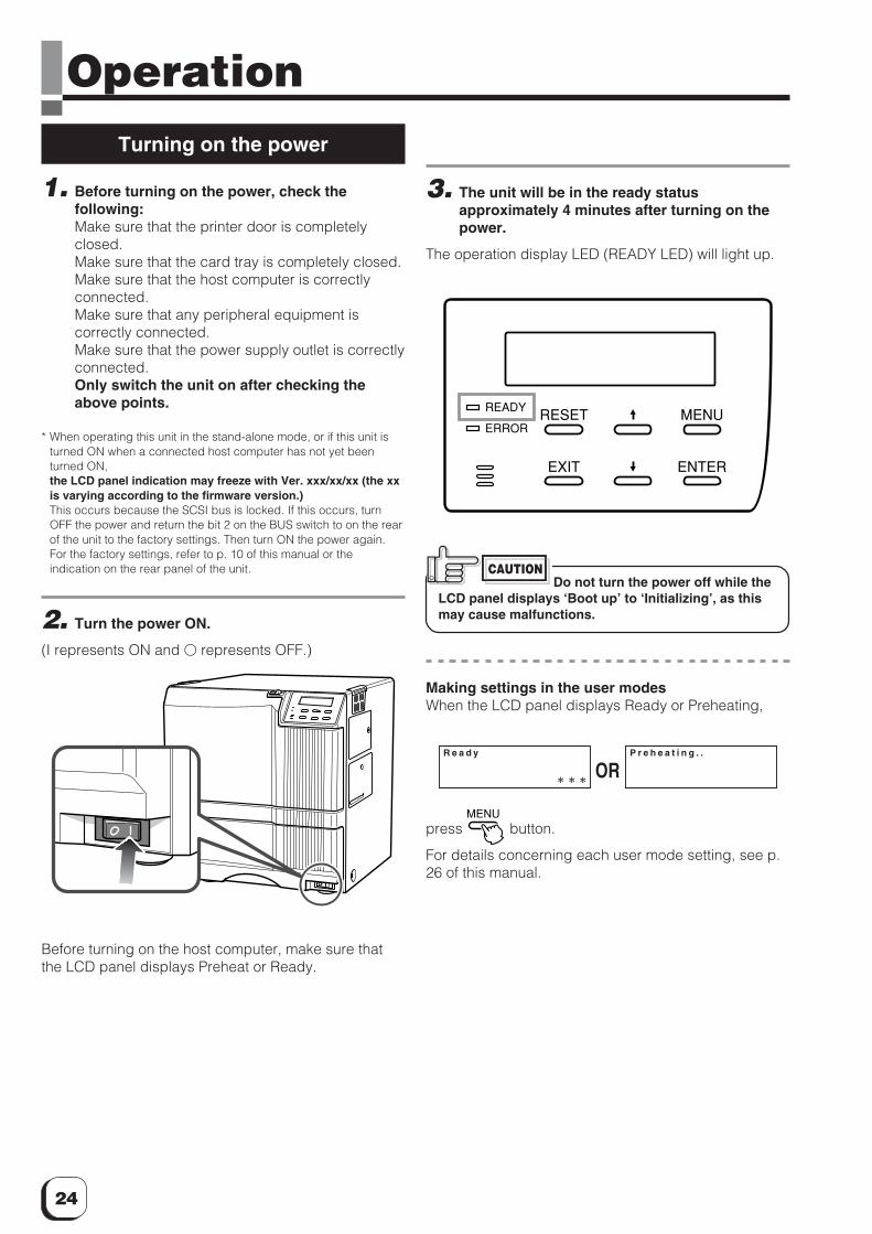
1. Before turning on the power, check thefollowing:Make sure that the printer door is completelyclosed.Make sure that the card tray is completely closed.Make sure that the host computer is correctlyconnected.Make sure that any peripheral equipment iscorrectly connected.Make sure that the power supply outlet is correctlyconnected.Only switch the unit on after checking theabove points.
* When operating this unit in the stand-alone mode, or if this unit isturned ON when a connected host computer has not yet beenturned ON,the LCD panel indication may freeze with Ver. xxx/xx/xx (the xxis varying according to the firmware version.)This occurs because the SCSI bus is locked. If this occurs, turnOFF the power and return the bit 2 on the BUS switch to on the rearof the unit to the factory settings. Then turn ON the power again.For the factory settings, refer to p. 10 of this manual or theindication on the rear panel of the unit.
2. Turn the power ON.
(I represents ON and � represents OFF.)
Before turning on the host computer, make sure thatthe LCD panel displays Preheat or Ready.
3. The unit will be in the ready statusapproximately 4 minutes after turning on thepower.
The operation display LED (READY LED) will light up.
Do not turn the power off while theLCD panel displays ‘Boot up’ to ‘Initializing’, as thismay cause malfunctions.
Making settings in the user modesWhen the LCD panel displays Ready or Preheating,
press MENU
button.
For details concerning each user mode setting, see p.26 of this manual.
RESET
EXIT
MENU
ENTER
READY
ERROR
ORR e a d y P r e h e a t i n g . .
CAUTION
25
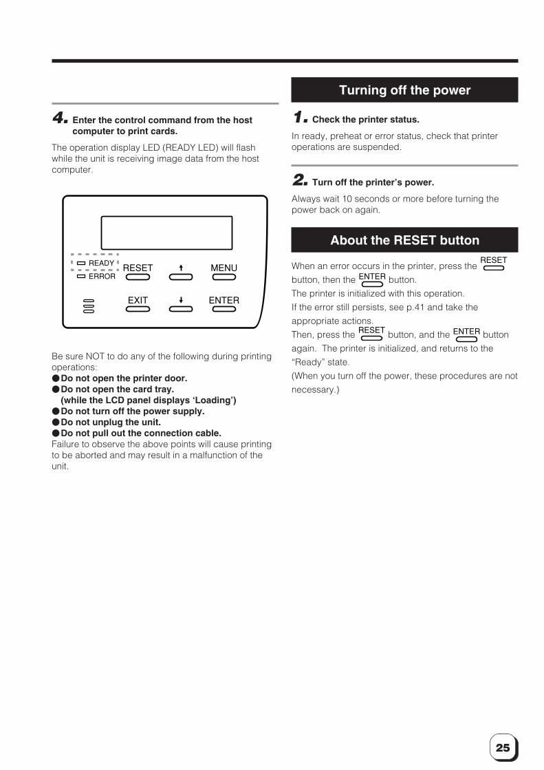
4. Enter the control command from the hostcomputer to print cards.
The operation display LED (READY LED) will flashwhile the unit is receiving image data from the hostcomputer.
Be sure NOT to do any of the following during printingoperations:�Do not open the printer door.�Do not open the card tray.
(while the LCD panel displays ‘Loading’)�Do not turn off the power supply.�Do not unplug the unit.�Do not pull out the connection cable.Failure to observe the above points will cause printingto be aborted and may result in a malfunction of theunit.
RESET
EXIT
MENU
ENTER
READY
ERROR
Turning off the power
1. Check the printer status.
In ready, preheat or error status, check that printeroperations are suspended.
2. Turn off the printer’s power.
Always wait 10 seconds or more before turning thepower back on again.
About the RESET button
When an error occurs in the printer, press the RESET
button, then the ENTER button.
The printer is initialized with this operation.
If the error still persists, see p.41 and take the
appropriate actions.
Then, press the RESET button, and the ENTER button
again. The printer is initialized, and returns to the
“Ready” state.
(When you turn off the power, these procedures are not
necessary.)
26
Operation (continued)
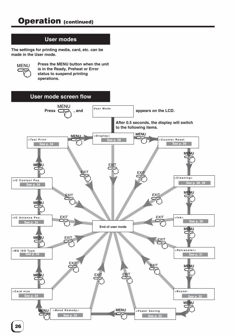
User modes
The settings for printing media, card, etc. can bemade in the User mode.
Press the MENU button when the unitis in the Ready, Preheat or Errorstatus to suspend printingoperations.
User mode screen flow
MENU
MENU
MENU
MENU
MENU
MENU
MENU
MENU
MENU
MENU
MENU
MENU
MENU MENU
MENU
MENU
MENU
MENU
MENU
MENU
MENU
MENU
MENU
MENU
MENU
MENU MENU
EXIT
EXIT
EXIT
EXIT
EXIT
EXITEXIT
EXIT
EXIT
EXIT
EXIT
EXIT EXIT> C l e a n i n g >
> I n k >
> R e t r a n s f e r >
> B u z z e r
> T e s t P r i n t
> P o w e r S a v i n g> B e n d R e m e d y >
> C a r d s i z e
> M G I S O T y p e
> I C A n t e n n a P o s .
> C o u n t e r R e s e t
> D i s p l a y >
> I C C o n t a c t P o s .
U s e r M o d eMENUPress , and appears on the LCD.
After 0.5 seconds, the display will switchto the following items.
See p. 34See p. 28
See p. 34
See p. 34
See p. 34
See p. 34
See p. 33 See p. 32
See p. 38, 39
See p. 30
See p. 31
See p. 32
See p. 29
End of user mode
27
(to the next page)
User mode settings
> B e n d R e m e d y >
> R e t r a n s f e r > > > M e d i a T y p e
> > T e m p . L e v e l
> > S p e e d ( F r o n t )
> > S p e e d ( B a c k )
S t a n d a r d : 0
0 ( S t a n d a r d )
- 2
- 2
Standard : 0
Standard
0
+2
+2
0
+2
None
YMCK : 0
0
0
0
SKY BLUE
off
Standard
Hi-Co
On
Total
> > T e m p L e v e l
> > S p e e d
> > C o o l i n g T i m e
o f f
- 2
- 2
> I n k > > > I n k T y p e
> > B l a c k L e v e l
Y M C K : 0
0 ( S t a n d a r d )
> > B l a c k M o d e
> > S P - I n k 1
S t a n d a r d
- 3
> D i s p l a y >
> P o w e r S a v i n g
> > C o u n t e r
> > C o n t r a s t
> > B a c k C o l o r
To t a l
- 2
B L U E
> C l e a n i n g >
> C a r d S i z e
> M G I S O T y p e
> B u z z e r
> T e s t P r i n t
> C o u n t e r R e s e t
O f f
O K ?
S t a n d a r d
L o - C o
O n
O K ?
O K ?
> I C A n t e n n a P o s .
N o n e
> I c C o n t a c t P o s .
N o n e
> > S P - I n k 2 L e v e l
Main menu Submenu Factory setting
Display mode
Ink mode
Retransfer mode
Bend Remedymode
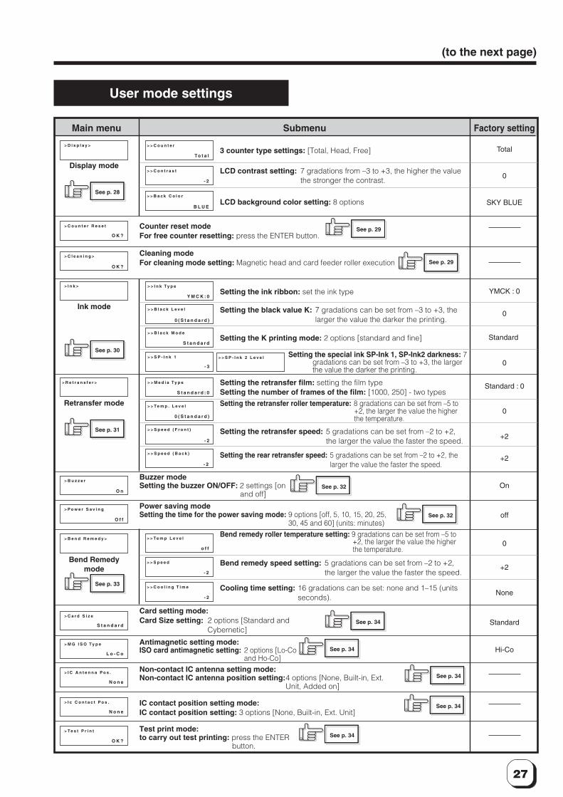
3 counter type settings: [Total, Head, Free]
LCD contrast setting: 7 gradations from –3 to +3, the higher the valuethe stronger the contrast.
LCD background color setting: 8 optionsSee p. 28
See p. 30
See p. 31
See p. 33
See p. 29
See p. 29
See p. 32
See p. 32
See p. 34
See p. 34
See p. 34
See p. 34
See p. 34
Counter reset modeFor free counter resetting: press the ENTER button.
Cleaning modeFor cleaning mode setting: Magnetic head and card feeder roller execution
Setting the ink ribbon: set the ink type
Setting the black value K: 7 gradations can be set from –3 to +3, thelarger the value the darker the printing.
Setting the K printing mode: 2 options [standard and fine]
Setting the retransfer film: setting the film typeSetting the number of frames of the film: [1000, 250] - two typesSetting the retransfer roller temperature: 8 gradations can be set from –5 to
+2, the larger the value the higherthe temperature.
Setting the retransfer speed: 5 gradations can be set from –2 to +2,the larger the value the faster the speed.
Setting the rear retransfer speed: 5 gradations can be set from –2 to +2, thelarger the value the faster the speed.
Buzzer modeSetting the buzzer ON/OFF: 2 settings [on
and off]
Power saving modeSetting the time for the power saving mode: 9 options [off, 5, 10, 15, 20, 25,
30, 45 and 60] (units: minutes)Bend remedy roller temperature setting: 9 gradations can be set from –5 to
+2, the larger the value the higherthe temperature.
Bend remedy speed setting: 5 gradations can be set from –2 to +2,the larger the value the faster the speed.
Cooling time setting: 16 gradations can be set: none and 1–15 (unitsseconds).
Card setting mode:Card Size setting: 2 options [Standard and
Cybernetic]
Antimagnetic setting mode:ISO card antimagnetic setting: 2 options [Lo-Co
and Ho-Co]Non-contact IC antenna setting mode:Non-contact IC antenna position setting:4 options [None, Built-in, Ext.
Unit, Added on]
IC contact position setting mode:IC contact position setting: 3 options [None, Built-in, Ext. Unit]
Test print mode:to carry out test printing: press the ENTER
button.
Setting the special ink SP-Ink 1, SP-Ink2 darkness: 7gradations can be set from –3 to +3, the largerthe value the darker the printing.
28
Operation (continued)
Display mode settings
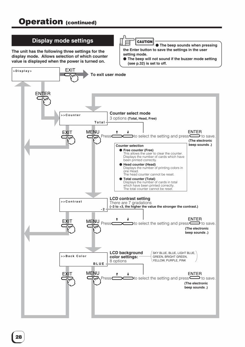
The unit has the following three settings for thedisplay mode. Allows selection of which countervalue is displayed when the power is turned on.
CAUTION� The beep sounds when pressing
the Enter button to save the settings in the usersetting mode.� The beep will not sound if the buzzer mode setting
(see p.32) is set to off.
> D i s p l a y >
> > C o u n t e r
> > C o n t r a s t
> > B a c k C o l o r
To t a l
- 2
B L U E
ENTER
ENTER
ENTER
MENU
MENU
MENU
EXIT
EXIT
EXIT
ENTER
EXIT
SKY BLUE, BLUE, LIGHT BLUE, GREEN, BRIGHT GREEN, YELLOW, PURPLE, PINK
To exit user mode
Counter select mode3 options (Total, Head, Free)
Press to select the setting and press to save.
Counter selection� Free counter (Free)
This allows the user to clear the counter.Displays the number of cards which havebeen printed correctly.
� Head counter (Head)Displays the number of printing colors inone Head.The head counter cannot be reset.
� Total counter (Total)Displays the number of cards in totalwhich have been printed correctly.The total counter cannot be reset.
LCD contrast settingThere are 7 gradations(–3 to +3, the higher the value the stronger the contrast.)
LCD backgroundcolor settings:8 options
Press to select the setting and press to save.
Press to select the setting and press to save.
(The electronicbeep sounds .)
(The electronicbeep sounds .)
(The electronicbeep sounds .)
29
(to the next page)
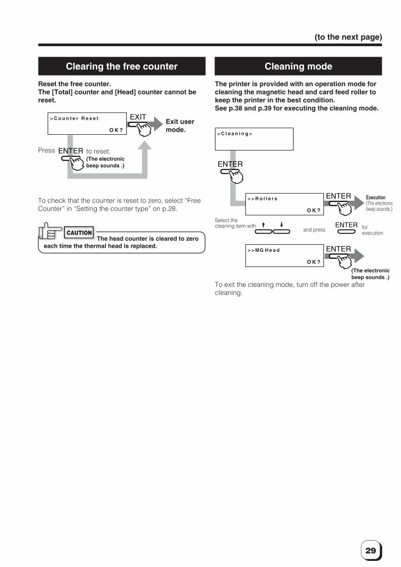
Clearing the free counter
Reset the free counter.The [Total] counter and [Head] counter cannot bereset.
Cleaning mode
The printer is provided with an operation mode forcleaning the magnetic head and card feed roller tokeep the printer in the best condition.See p.38 and p.39 for executing the cleaning mode.
> C o u n t e r R e s e t
O K ?
EXIT
ENTER
Exit usermode.
Press to reset.(The electronicbeep sounds .)
To check that the counter is reset to zero, select “FreeCounter” in “Setting the counter type” on p.28.
CAUTIONThe head counter is cleared to zero
each time the thermal head is replaced.
> C l e a n i n g >
> > R o l l e r s
O K ?
> > MG H e a d
O K ?
ENTER
ENTER
ENTER
ENTER
Execution(The electronicbeep sounds.)
and press
Select thecleaning item with
To exit the cleaning mode, turn off the power aftercleaning.
forexecution.
(The electronicbeep sounds .)
30
Operation (continued)
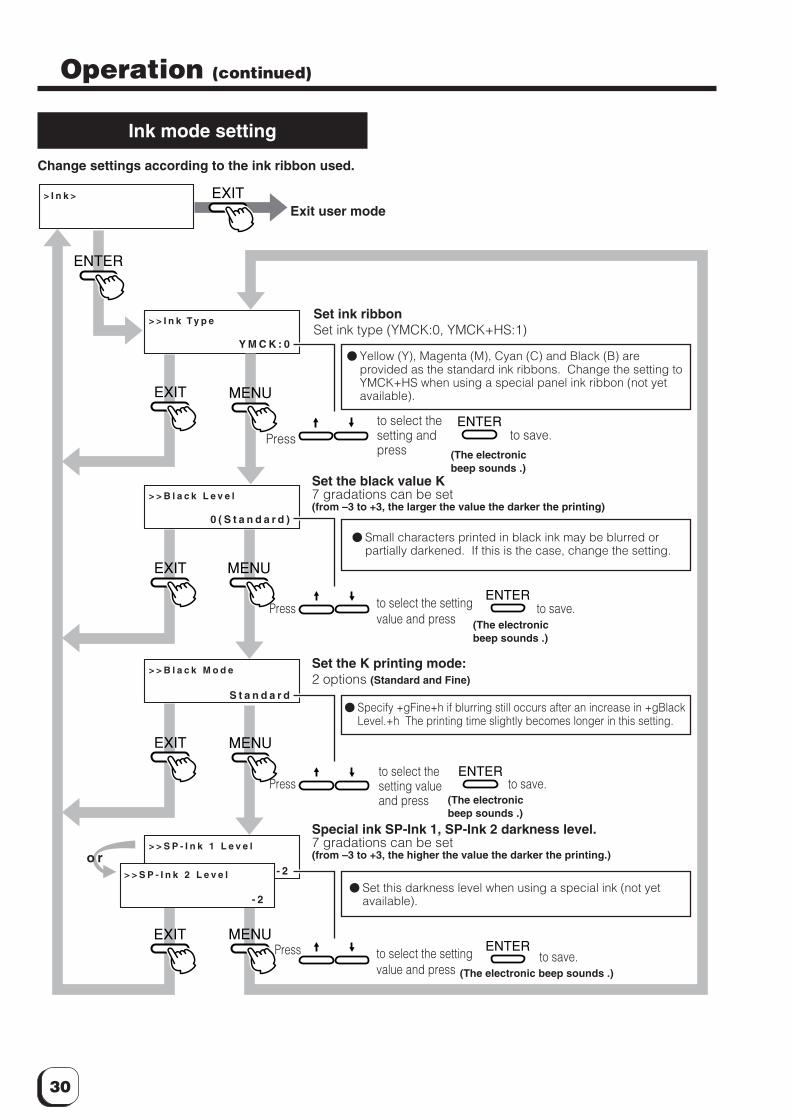
Ink mode setting
Change settings according to the ink ribbon used.
> I n k >
> > B l a c k L e v e l
> > B l a c k M o d e
> > I n k T y p e
Y M C K : 0
0 ( S t a n d a r d )
S t a n d a r d
> > S P - I n k 1 L e v e l
- 2
ENTER
ENTER
ENTER
ENTER
MENU
MENU
MENU
MENU
EXIT
EXIT
EXIT
EXIT
ENTER
EXIT
> > S P - I n k 2 L e v e l
- 2
o r
Exit user mode
Set ink ribbonSet ink type (YMCK:0, YMCK+HS:1)
(The electronicbeep sounds .)
Set the black value K7 gradations can be set(from –3 to +3, the larger the value the darker the printing)
Set the K printing mode:2 options (Standard and Fine)
Special ink SP-Ink 1, SP-Ink 2 darkness level.7 gradations can be set(from –3 to +3, the higher the value the darker the printing.)
Press
to save.
to save.to select thesetting andpress
Press to select the settingvalue and press
to save.Pressto select thesetting valueand press
to save.Press to select the settingvalue and press
� Yellow (Y), Magenta (M), Cyan (C) and Black (B) areprovided as the standard ink ribbons. Change the setting toYMCK+HS when using a special panel ink ribbon (not yetavailable).
� Small characters printed in black ink may be blurred orpartially darkened. If this is the case, change the setting.
� Specify +gFine+h if blurring still occurs after an increase in +gBlackLevel.+h The printing time slightly becomes longer in this setting.
� Set this darkness level when using a special ink (not yetavailable).
(The electronicbeep sounds .)
(The electronicbeep sounds .)
(The electronic beep sounds .)
31
(to the next page)
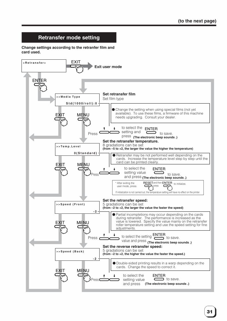
Retransfer mode setting
Change settings according to the retranfer film andcard used.
> R e t r a n s f e r >
> > M e d i a T y p e
> > T e m p . L e v e l
> > S p e e d ( F r o n t )
> > S p e e d ( B a c k )
S t d ( 1 0 0 0 / r o l l ) : 0
0 ( S t a n d a r d )
- 2
- 2
ENTER
ENTER
ENTER
ENTER
RESET ENTER
MENU
MENU
MENU
MENU
EXIT
EXIT
EXIT
EXIT
ENTER
EXIT
Set retransfer filmSet film type
(The electronic beep sounds .)Set the retransfer temperature.8 gradations can be set(from –5 to +2, the larger the value the higher the temperature)
Set the reverse retransfer speed:5 gradations can be set(from –2 to +2, the higher the value the faster the speed.)
Exit user mode
If initialization is not carried out, the temperature setting will have no effect on the printer.
Set the retransfer speed:5 gradations can be set(from –2 to +2, the larger the value the faster the speed)
to select thesetting andpress
to select thesetting valueand press
to select the settingvalue and press
to select thesetting valueand press
Press to save.
Press to save.
Press to save.
Press to save.
� Change the setting when using special films (not yetavailable). To use these films, a firmware of this machineneeds upgrading. Consult your dealer.
� Retransfer may be not performed well depending on thecards. Increase the temperature level step by step until thecard can be printed clearly.
� Partial incompletions may occur depending on the cardsduring retransfer. The performance is increased as thevalue is lowered. Specify the value mainly on the retransferroller temperature setting and use the speed setting for fineadjustments.
� Double-sided printing results in a warp depending on thecards. Change the speed to correct it.
* After exiting theuser mode, press
and thenpress
to initialize.
(The electronic beep sounds .)
(The electronic beep sounds .)
(The electronic beep sounds .)
32
Operation (continued)
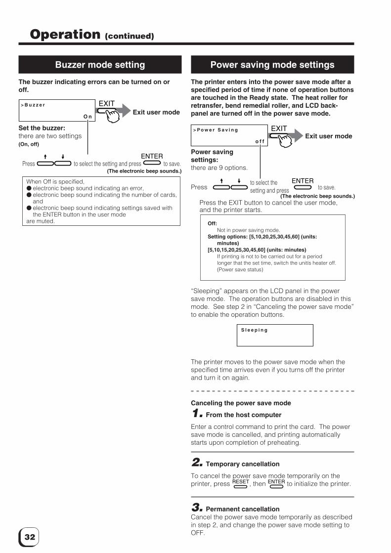
Buzzer mode setting
The buzzer indicating errors can be turned on oroff.
Power saving mode settings
The printer enters into the power save mode after aspecified period of time if none of operation buttonsare touched in the Ready state. The heat roller forretransfer, bend remedial roller, and LCD back-panel are turned off in the power save mode.
> B u z z e r
O n
EXIT
ENTER
Exit user mode
Set the buzzer:there are two settings(On, off)
Press to select the setting and press to save.(The electronic beep sounds.)
> P o w e r S a v i n g
o f f
EXIT
ENTER
Exit user mode
Power savingsettings:there are 9 options.
(The electronic beep sounds.)
Off:Not in power saving mode.
Setting options: [5,10,20,25,30,45,60] (units:minutes)
[5,10,15,20,25,30,45,60] (units: minutes)If printing is not to be carried out for a periodlonger that the set time, switch the unitís heater off.(Power save status)
When Off is specified,� electronic beep sound indicating an error,� electronic beep sound indicating the number of cards,
and� electronic beep sound indicating settings saved with
the ENTER button in the user modeare muted.
Pressto select thesetting and press to save.
Press the EXIT button to cancel the user mode,and the printer starts.
“Sleeping” appears on the LCD panel in the powersave mode. The operation buttons are disabled in thismode. See step 2 in “Canceling the power save mode”to enable the operation buttons.
The printer moves to the power save mode when thespecified time arrives even if you turns off the printerand turn it on again.
Canceling the power save mode
1. From the host computer
Enter a control command to print the card. The powersave mode is cancelled, and printing automaticallystarts upon completion of preheating.
2. Temporary cancellation
To cancel the power save mode temporarily on theprinter, press RESET, then ENTER to initialize the printer.
3. Permanent cancellationCancel the power save mode temporarily as describedin step 2, and change the power save mode setting toOFF.
S l e e p i n g
33
(to the next page)
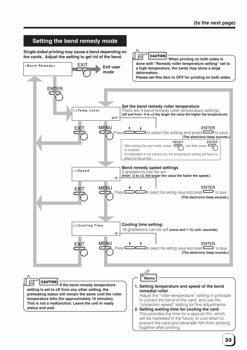
Setting the bend remedy mode
Single-sided printing may cause a bend depending onthe cards. Adjust the setting to get rid of the bend.
CAUTION
> B e n d R e m e d y >
> > T e m p L e v e l
> > S p e e d
> > C o o l i n g T i m e
o f f
- 2
- 2
ENTER
ENTER
MENU
MENU
MENU
EXIT
EXIT
EXIT
ENTER
EXIT
RESET ENTER
ENTER
Set the bend remedy roller temperatureThere are 9 bend remedy roller temperature settings:(off and from –5 to +2 the larger the value the higher the temperature).
Bend remedy speed settings5 gradations can be set(from –2 to +2, the larger the value the faster the speed.)
Exit usermode
* After exiting the user mode, press and then pressto initialize.If initialization is not carried out, the temperature setting will have noeffect on the printer.
Cooling time setting:16 gradations can be set (none and 1-15, unit: seconds).
Press to select the setting and press to save.
Press to select the setting value and press to save.
Press to select the setting value and press to save.
If the bend remedy temperaturesetting is set to off from any other setting, thepreheating status will remain the same until the rollertemperature falls (for approximately 10 minutes).This is not a malfunction. Leave the unit in readystatus and wait.
Memo
1. Setting temperature and speed of the bendremedial rollerAdjust the “roller temperature” setting in principleto correct the bend of the card, and use the“correction speed” setting for fine adjustments.
2. Setting waiting time for cooling the cardThis provides the time for a special film, whichwill be marketed in the future, to cool down toprevent the card and retransfer film from stickingtogether after printing.
(The electronic beep sounds.)
(The electronic beep sounds.)
(The electronic beep sounds.)
CAUTIONWhen printing on both sides is
done with “Remedy roller temperature setting” set toa high temperature, the cards may show a largedeformation.Please set this item to OFF for printing on both sides.
34
Operation (continued)
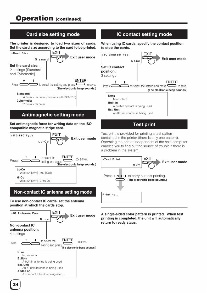
Card size setting mode
The printer is designed to load two sizes of cards.Set the card size according to the card to be printed.
> C a r d S i z e
S t a n a r d
EXIT
ENTER
Exit user mode
Set the card size:2 settings [Standardand Cybernetic]
Press to select the setting and press to save.(The electronic beep sounds.)
Standard:54.0mm × 85.6mm (complies with ISO7810)
Cybernetic:57.5mm × 85.0mm
Antimagnetic setting mode
Set antimagnetic force for writing data on the ISOcompatible magnetic stripe card.
> M G I S O T y p e
L o - C o
EXIT
ENTER
Exit user mode
(The electronic beep sounds.)
Lo-Co238×102 [A/m] (300 [Oe])
Hi-Co218×103 [A/m] (2750 Oe])
Non-contact IC antenna setting mode
To use non-contact IC cards, set the antennaposition at which the cards stop.
> I C C o n t a c t P o s .
N o n e
EXIT
ENTER
Exit user mode
Set IC contactposition:3 settings
Press to select the setting and press to save.(The electronic beep sounds.)
NoneNo contact
Built-inA built-in contact is being used
Ext. UnitAn IC unit contact is being used
IC contact setting mode
When using IC cards, specify the contact positionto stop the cards.
> T e s t P r i n t
O K ?
P r i n t i n g . .
ENTER
EXIT
Test print
Test print is provided for printing a test patterncontained in the printer (there is only one pattern).Operating the printer independent of the host computerenables you to find out the source of trouble if there isa problem in the system.
Exit user mode
A single-sided color pattern is printed. When testprinting is completed, the unit will automaticallyreturn to ready staus.
Pressto select thesetting and press
to save.
Press to carry out test printing. (The electronic beep sounds.)
> I C A n t e n n a P o s .
N o n e
EXIT
ENTER
Non-contact ICantenna position:4 settings
Exit user mode
(The electronic beep sounds.)
Press to select thesetting and press
to save.
NoneNo antenna
Built-inA built-in antenna is being used
Ext. UnitAn IC unit antenna is being used
Added onA compact IC unit is being used.
35
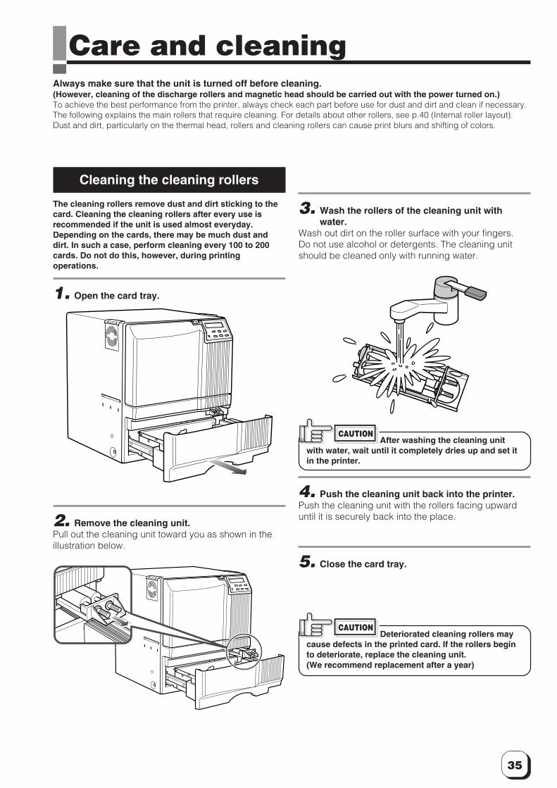
Care and cleaningAlways make sure that the unit is turned off before cleaning.(However, cleaning of the discharge rollers and magnetic head should be carried out with the power turned on.)To achieve the best performance from the printer, always check each part before use for dust and dirt and clean if necessary.The following explains the main rollers that require cleaning. For details about other rollers, see p.40 (Internal roller layout).Dust and dirt, particularly on the thermal head, rollers and cleaning rollers can cause print blurs and shifting of colors.
3. Wash the rollers of the cleaning unit withwater.
Wash out dirt on the roller surface with your fingers.Do not use alcohol or detergents. The cleaning unitshould be cleaned only with running water.
4. Push the cleaning unit back into the printer.Push the cleaning unit with the rollers facing upwarduntil it is securely back into the place.
5. Close the card tray.
After washing the cleaning unitwith water, wait until it completely dries up and set itin the printer.
CAUTION
Deteriorated cleaning rollers maycause defects in the printed card. If the rollers beginto deteriorate, replace the cleaning unit.(We recommend replacement after a year)
CAUTION
Cleaning the cleaning rollers
The cleaning rollers remove dust and dirt sticking to thecard. Cleaning the cleaning rollers after every use isrecommended if the unit is used almost everyday.Depending on the cards, there may be much dust anddirt. In such a case, perform cleaning every 100 to 200cards. Do not do this, however, during printingoperations.
1. Open the card tray.
2. Remove the cleaning unit.Pull out the cleaning unit toward you as shown in theillustration below.
36
Cleaning (continued)
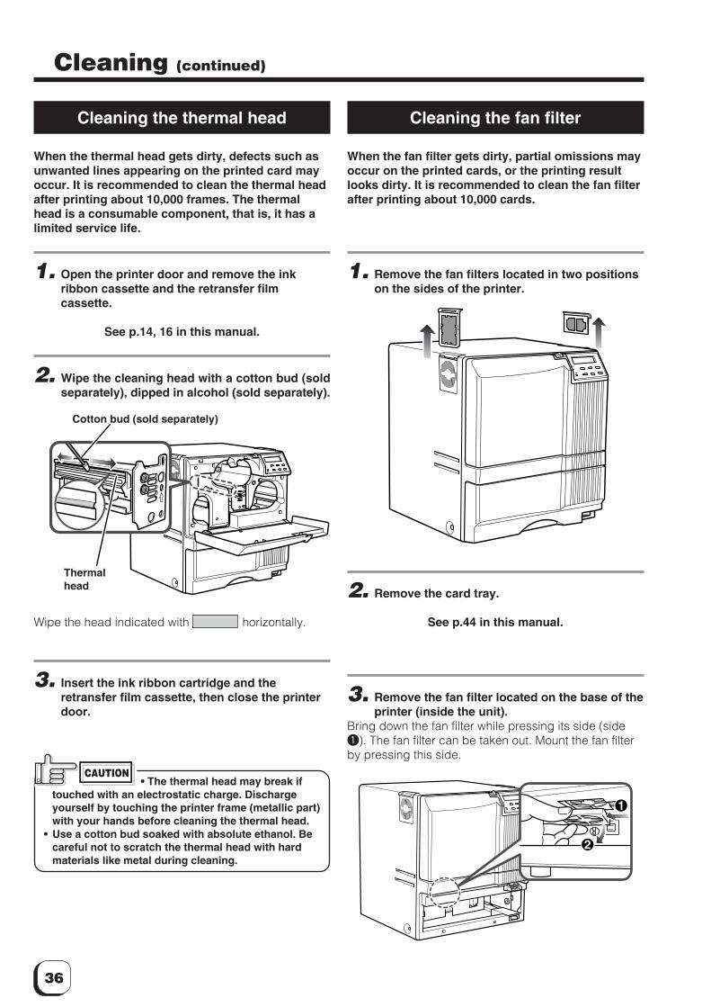
Cleaning the thermal head
When the thermal head gets dirty, defects such asunwanted lines appearing on the printed card mayoccur. It is recommended to clean the thermal headafter printing about 10,000 frames. The thermalhead is a consumable component, that is, it has alimited service life.
1. Open the printer door and remove the inkribbon cassette and the retransfer filmcassette.
See p.14, 16 in this manual.
2. Wipe the cleaning head with a cotton bud (soldseparately), dipped in alcohol (sold separately).
Wipe the head indicated with horizontally.
3. Insert the ink ribbon cartridge and theretransfer film cassette, then close the printerdoor.
Cleaning the fan filter
When the fan filter gets dirty, partial omissions mayoccur on the printed cards, or the printing resultlooks dirty. It is recommended to clean the fan filterafter printing about 10,000 cards.
1. Remove the fan filters located in two positionson the sides of the printer.
2. Remove the card tray.
See p.44 in this manual.
3. Remove the fan filter located on the base of theprinter (inside the unit).
Bring down the fan filter while pressing its side (side1). The fan filter can be taken out. Mount the fan filterby pressing this side.
Thermalhead
Cotton bud (sold separately)
• The thermal head may break iftouched with an electrostatic charge. Dischargeyourself by touching the printer frame (metallic part)with your hands before cleaning the thermal head.
• Use a cotton bud soaked with absolute ethanol. Becareful not to scratch the thermal head with hardmaterials like metal during cleaning.
CAUTION
1
2
37
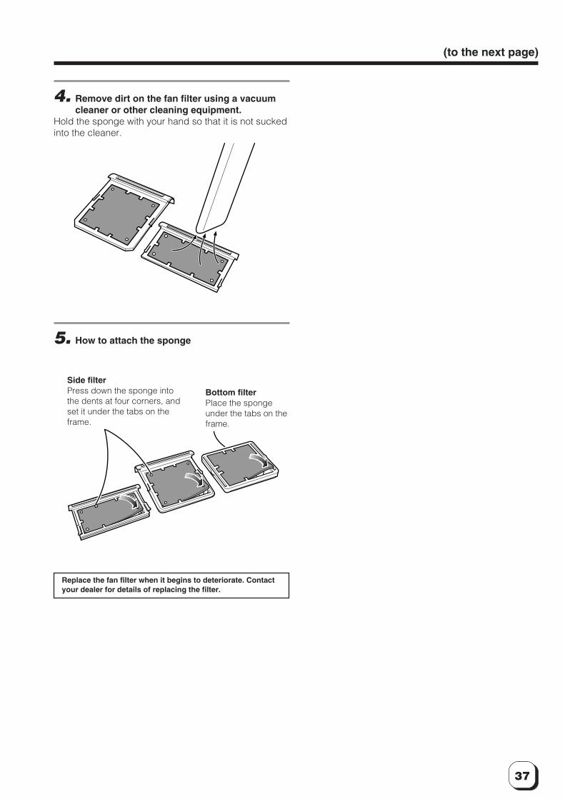
(to the next page)
4. Remove dirt on the fan filter using a vacuumcleaner or other cleaning equipment.
Hold the sponge with your hand so that it is not suckedinto the cleaner.
5. How to attach the sponge
Side filterPress down the sponge intothe dents at four corners, andset it under the tabs on theframe.
Replace the fan filter when it begins to deteriorate. Contactyour dealer for details of replacing the filter.
Bottom filterPlace the spongeunder the tabs on theframe.
38
Cleaning the card feed rollers
Dirty rollers are the major cause of jamming of thecards. It is recommended to clean the rollers onceafter printing about 1,000 cards. It is alsorecommended to carry out cleaning before thework, because the retransfer roller (heat roller) doesnot operate while it is hot.
1. Remove the retransfer film cassette.
See p.16 in this manual.
2. Turn on the power of the printer.The printer initializes, and the [No Cassette] error isindicated.
3. From user mode select cleaning mode.
4. Press the ENTER button. Select [Rollers] with↑ and ↓ buttons, and press the ENTER button.
See p.26 in this manual.
Insert the cleaning card in about 10 seconds. If youfails to set the card within this time, the printer returns to“Start OK?” Press the ENTER button again to proceed.
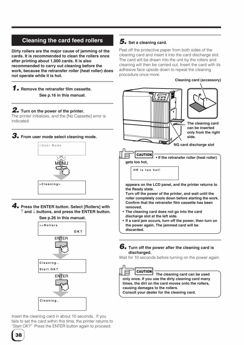
5. Set a cleaning card.
Peel off the protective paper from both sides of thecleaning card and insert it into the card discharge slot.The card will be drawn into the unit by the rollers andcleaning will then be carried out. Insert the card with itsadhesive face upside down to repeat the cleaningprocedure once more.
> C l e a n i n g >
> U s e r M o d e
MENU
> > R o l l e r s
O K ?
C l e a n i n g . .
S t a r t O K ?
ENTER
C l e a n i n g . .
ENTER
• If the retransfer roller (heat roller)gets too hot,
appears on the LCD panel, and the printer returns tothe Ready state.Turn off the power of the printer, and wait until theroller completely cools down before starting the work.Confirm that the retransfer film cassette has beenremoved.
• The cleaning card does not go into the carddischarge slot at the left side.
• If a card jam occurs, turn off the power, then turn onthe power again. The jammed card will bediscarded.
CAUTION
H R i s t o o h o t !
Cleaning card (accessory)
The cleaning cardcan be insertedonly from the rightside.
NG card discharge slot
6. Turn off the power after the cleaning card isdischarged.
Wait for 10 seconds before turning on the power again.
The cleaning card can be usedonly once. If you use the dirty cleaning card manytimes, the dirt on the card moves onto the rollers,causing damages to the rollers.Consult your dealer for the cleaning card.
CAUTION
39
Cleaning the card feed rollers andheat rollers
Dirty magnetic head will cause a write/read error. Itis recommended to clean the magnetic head afterprinting about 1,000 cards. Cleaning the magnetichead is not necessary if the magnetic stripe card isnot used.
1. Keep the ink ribbon and retransfer filmcassettes in their mounting positions.
See p.14 to p.17 of this manual.
2. Turn on the power of the printer.Go to the next step when the printer is in the Preheat orReady state.
3. Specify the “cleaning” mode in the user mode.
See p.26 in this manual.
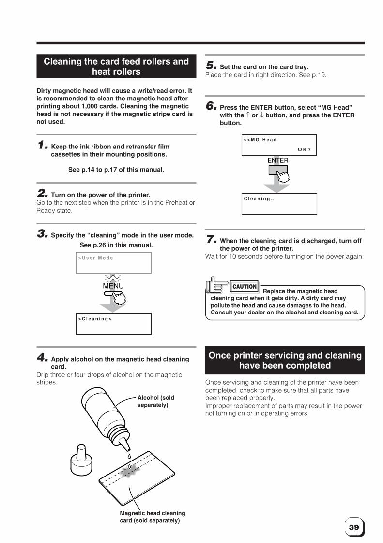
4. Apply alcohol on the magnetic head cleaningcard.
Drip three or four drops of alcohol on the magneticstripes.
> C l e a n i n g >
> U s e r M o d e
MENU
Magnetic head cleaningcard (sold separately)
Alcohol (soldseparately)
5. Set the card on the card tray.Place the card in right direction. See p.19.
6. Press the ENTER button, select “MG Head”with the ↑ or ↓ button, and press the ENTERbutton.
7. When the cleaning card is discharged, turn offthe power of the printer.
Wait for 10 seconds before turning on the power again.
> > M G H e a d
O K ?
C l e a n i n g . .
ENTER
Replace the magnetic headcleaning card when it gets dirty. A dirty card maypollute the head and cause damages to the head.Consult your dealer on the alcohol and cleaning card.
CAUTION
Once printer servicing and cleaninghave been completed
Once servicing and cleaning of the printer have beencompleted, check to make sure that all parts havebeen replaced properly.Improper replacement of parts may result in the powernot turning on or in operating errors.
40
J a m ( Tu r n O v e r )
J a m ( H o p p e r )
J a m ( Tr a n s f e r )
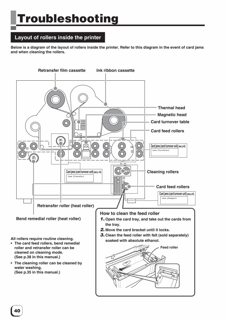
TroubleshootingLayout of rollers inside the printer
Below is a diagram of the layout of rollers inside the printer. Refer to this diagram in the event of card jamsand when cleaning the rollers.
Retransfer film cassette Ink ribbon cassette
Thermal head
Card feed rollers
Card jams (card turnover unit) (see p.45)
Card jams (card turnover unit) (see p.44)
Card jams (card turnover unit) (see p. 45) Cleaning rollers
Card feed rollers
Bend remedial roller (heat roller)
Retransfer roller (heat roller)
All rollers require routine cleaning.• The card feed rollers, bend remedial
roller and retransfer roller can becleaned on cleaning mode.(See p.38 in this manual.)
• The cleaning roller can be cleaned bywater washing.(See p.35 in this manual.)
Magnetic head
Card turnover table
How to clean the feed roller1. Open the card tray, and take out the cards from
the tray.2. Move the card bracket until it locks.3. Clean the feed roller with felt (sold separately)
soaked with absolute ethanol.
Feed roller
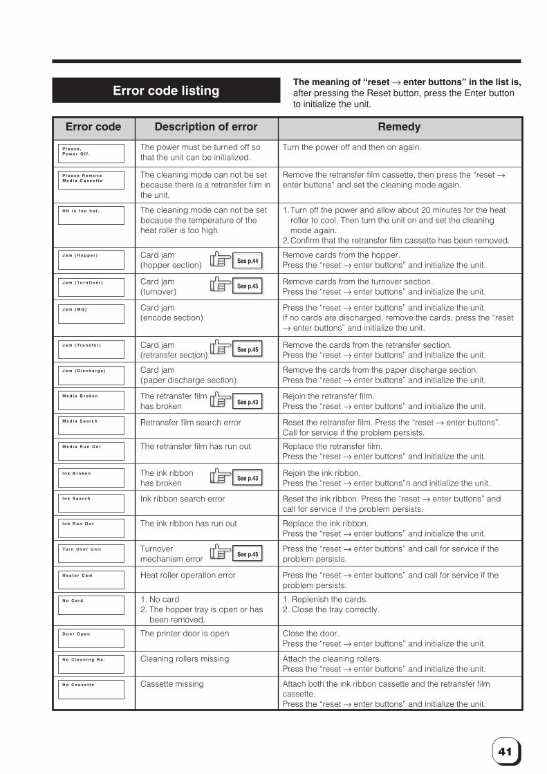
41
P l e a s e ,P o w e r O f f .
P l e a s e R e m o v eM e d i a C a s s e t t e
H R i s t o o h o t .
J a m ( H o p p e r )
J a m ( Tu r n O v e r )
J a m ( M G )
J a m ( Tr a n s f e r )
J a m ( D i s c h a r g e )
M e d i a B r o k e n
M e d i a S e a r c h
M e d i a R u n O u t
I n k B r o k e n
I n k S e a r c h
I n k R u n O u t
Tu r n O v e r U n i t
H e a t e r C a m
N o C a r d
D o o r O p e n
N o C l e a n i n g R o .
N o C a s s e t t e
Error code listingThe meaning of “reset → enter buttons” in the list is,after pressing the Reset button, press the Enter buttonto initialize the unit.
Error code Description of error Remedy
The power must be turned off sothat the unit can be initialized.
Turn the power off and then on again.
The cleaning mode can not be setbecause there is a retransfer film inthe unit.
Remove the retransfer film cassette, then press the “reset →enter buttons” and set the cleaning mode again.
The cleaning mode can not be setbecause the temperature of theheat roller is too high.
1.Turn off the power and allow about 20 minutes for the heatroller to cool. Then turn the unit on and set the cleaningmode again.
2.Confirm that the retransfer film cassette has been removed.
Card jam(hopper section)
Remove cards from the hopper.Press the “reset → enter buttons” and initialize the unit.
Card jam(turnover)
Remove cards from the turnover section.Press the “reset → enter buttons” and initialize the unit.
Card jam(encode section)
Press the “reset → enter buttons” and initialize the unit.If no cards are discharged, remove the cards, press the “reset→ enter buttons” and initialize the unit.
Card jam(retransfer section)
Remove the cards from the retransfer section.Press the “reset → enter buttons” and initialize the unit.
Card jam(paper discharge section)
Remove the cards from the paper discharge section.Press the “reset → enter buttons” and initialize the unit.
The retransfer filmhas broken
Rejoin the retransfer film.Press the “reset → enter buttons” and initialize the unit.
Retransfer film search error Reset the retransfer film. Press the “reset → enter buttons”.Call for service if the problem persists.
The retransfer film has run out Replace the retransfer film.Press the “reset → enter buttons” and initialize the unit.
The ink ribbonhas broken
Rejoin the ink ribbon.Press the “reset → enter buttons”n and initialize the unit.
Ink ribbon search error Reset the ink ribbon. Press the “reset → enter buttons” andcall for service if the problem persists.
The ink ribbon has run out Replace the ink ribbon.Press the “reset → enter buttons” and initialize the unit.
Turnovermechanism error
Press the “reset → enter buttons” and call for service if theproblem persists.
Heat roller operation error Press the “reset → enter buttons” and call for service if theproblem persists.
1. No card2. The hopper tray is open or has
been removed.
1. Replenish the cards.2. Close the tray correctly.
The printer door is open Close the door.Press the “reset → enter buttons” and initialize the unit.
Cleaning rollers missing Attach the cleaning rollers.Press the “reset → enter buttons” and initialize the unit.
Cassette missing Attach both the ink ribbon cassette and the retransfer filmcassette.Press the “reset → enter buttons” and initialize the unit.
See p.44
See p.45
See p.45
See p.43
See p.43
See p.45
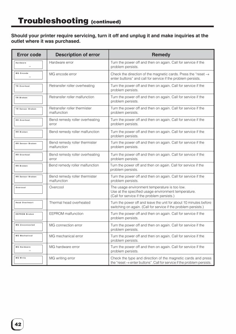
42
T R O v e r h e a t
T R B r o k e n
T R S e n s o r B r o k e n
R R O v e r h e a t
R R B r o k e n
R R S e n s o r B r o k e n
R R O v e r h e a t
R R B r o k e n
R R S e n s o r B r o k e n
O v e r c o o l
H e a d O v e r h e a r t
E E P R O M B r o k e n
M G U n c o n n e c t e d
M G M e c h a n i c a l
M G H a r d w a r e
* *
M G W r i t e
H a r d w a r e
* *
M G E n c o d e
* *
Error code Description of error Remedy
Retransfer roller overheating Turn the power off and then on again. Call for service if theproblem persists.
Troubleshooting (continued)
Should your printer require servicing, turn it off and unplug it and make inquiries at theoutlet where it was purchased.
Retransfer roller malfunction Turn the power off and then on again. Call for service if theproblem persists.
Retransfer roller thermistermalfunction
Turn the power off and then on again. Call for service if theproblem persists.
Bend remedy roller overheatingerror
Turn the power off and then on again. Call for service if theproblem persists.
Bend remedy roller malfunction Turn the power off and then on again. Call for service if theproblem persists.
Bend remedy roller thermistermalfunction
Turn the power off and then on again. Call for service if theproblem persists.
Overcool The usage environment temperature is too low.Use at the specified usage environment temperature.(Call for service if the problem persists.)
Thermal head overheated Turn the power off and leave the unit for about 10 minutes beforeswitching on again. (Call for service if the problem persists.)
EEPROM malfunction Turn the power off and then on again. Call for service if theproblem persists.
MG connection error Turn the power off and then on again. Call for service if theproblem persists.
MG mechanical error Turn the power off and then on again. Call for service if theproblem persists.
MG hardware error Turn the power off and then on again. Call for service if theproblem persists.
MG writing error Check the type and direction of the magnetic cards and pressthe “reset → enter buttons”. Call for service if the problem persists.
Hardware error Turn the power off and then on again. Call for service if theproblem persists.
MG encode error Check the direction of the magnetic cards. Press the “reset →enter buttons” and call for service if the problem persists.
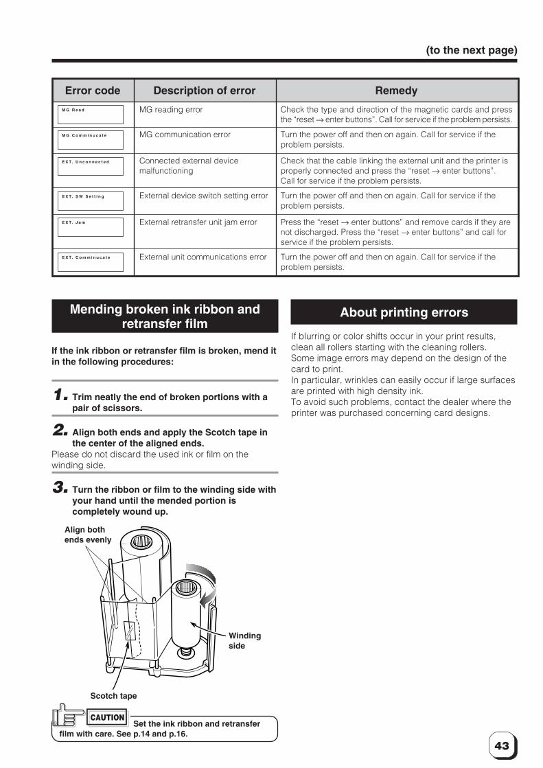
43
(to the next page)
E X T. U n c o n n e c t e d
E X T. S W S e t t i n g
E X T. J a m
E X T. C o m m i n u c a t e
M G R e a d
M G C o m m i n u c a t e
Error code Description of error Remedy
Connected external devicemalfunctioning
Check that the cable linking the external unit and the printer isproperly connected and press the “reset → enter buttons”.Call for service if the problem persists.
External device switch setting error Turn the power off and then on again. Call for service if theproblem persists.
External retransfer unit jam error Press the “reset → enter buttons” and remove cards if they arenot discharged. Press the “reset → enter buttons” and call forservice if the problem persists.
External unit communications error Turn the power off and then on again. Call for service if theproblem persists.
Mending broken ink ribbon andretransfer film
If the ink ribbon or retransfer film is broken, mend itin the following procedures:
1. Trim neatly the end of broken portions with apair of scissors.
2. Align both ends and apply the Scotch tape inthe center of the aligned ends.
Please do not discard the used ink or film on thewinding side.
3. Turn the ribbon or film to the winding side withyour hand until the mended portion iscompletely wound up.
About printing errors
If blurring or color shifts occur in your print results,clean all rollers starting with the cleaning rollers.Some image errors may depend on the design of thecard to print.In particular, wrinkles can easily occur if large surfacesare printed with high density ink.To avoid such problems, contact the dealer where theprinter was purchased concerning card designs.
Align bothends evenly
Scotch tape
Windingside
Set the ink ribbon and retransferfilm with care. See p.14 and p.16.
CAUTION
MG reading error Check the type and direction of the magnetic cards and pressthe “reset → enter buttons”. Call for service if the problem persists.
MG communication error Turn the power off and then on again. Call for service if theproblem persists.
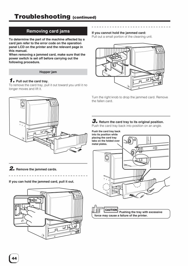
44
Troubleshooting (continued)
Removing card jams
To determine the part of the machine affected by acard jam refer to the error code on the operationpanel LCD on the printer and the relevant page inthis manual.When removing a jammed card, make sure that thepower switch is set off before carrying out thefollowing procedure.
Hopper jam
1. Pull out the card tray.To remove the card tray, pull it out toward you until it nolonger moves and lift it.
2. Remove the jammed cards.
If you can hold the jammed card, pull it out.
3. Return the card tray to its original position.Push the card tray back into position on an angle.
Push the card tray backinto its position whileplacing the card traytabs on the folded overmetal plates.
If you cannot hold the jammed card:Pull out a small portion of the cleaning unit.
Turn the right knob to drop the jammed card. Removethe fallen card.
Pushing the tray with excessiveforce may cause a failure of the printer.
CAUTION
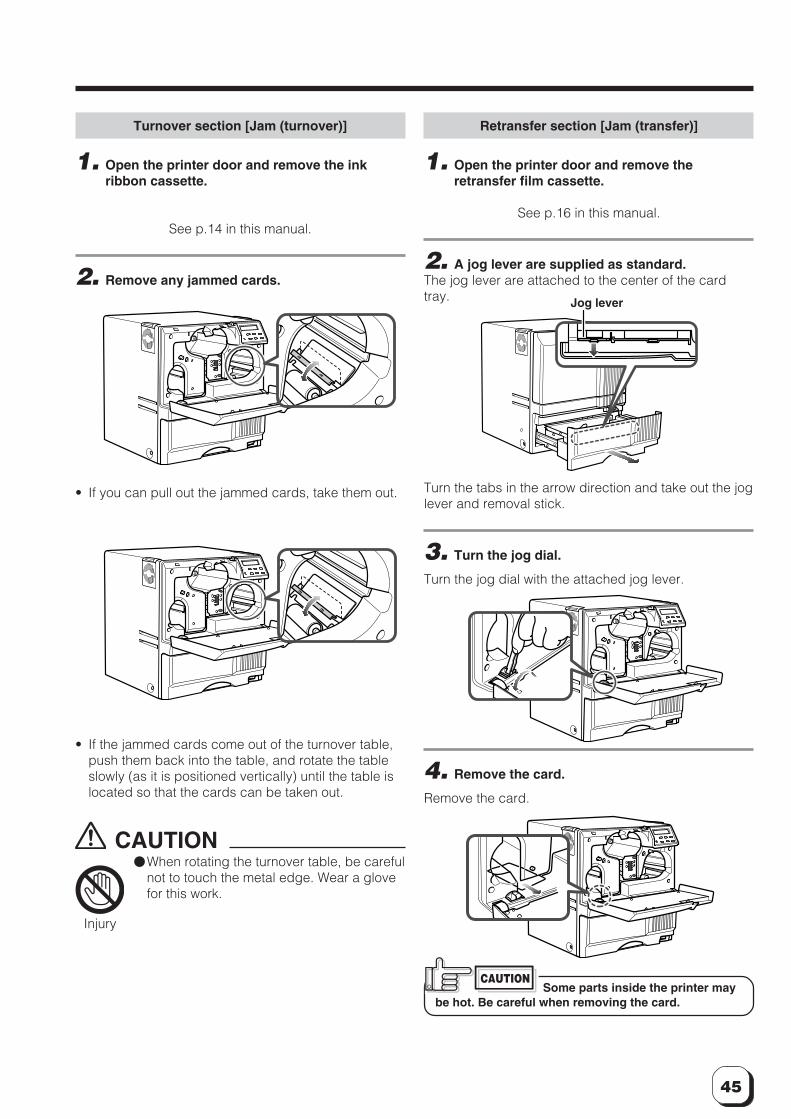
45
Turnover section [Jam (turnover)]
1. Open the printer door and remove the inkribbon cassette.
See p.14 in this manual.
2. Remove any jammed cards.
Retransfer section [Jam (transfer)]
1. Open the printer door and remove theretransfer film cassette.
See p.16 in this manual.
2. A jog lever are supplied as standard.The jog lever are attached to the center of the cardtray.
Turn the tabs in the arrow direction and take out the joglever and removal stick.
3. Turn the jog dial.
Turn the jog dial with the attached jog lever.
4. Remove the card.
Remove the card.
Some parts inside the printer maybe hot. Be careful when removing the card.
CAUTION
• If the jammed cards come out of the turnover table,push them back into the table, and rotate the tableslowly (as it is positioned vertically) until the table islocated so that the cards can be taken out.
CAUTION�When rotating the turnover table, be careful
not to touch the metal edge. Wear a glovefor this work.
Injury
• If you can pull out the jammed cards, take them out.
Jog lever
46
SpecificationsMain specifications
Recording method : Sublimation type retransferFeed format : Automatic feedRecording density : 300 dpiExpression gradation : 256 gradations for each colorPrinting time : Approx. 29 seconds (for single-
sided printing, excluding datatransfer time)
Interface : Compliant with SCSI II (standard)Operating environment conditions
Temperature: 15°C ~ 30°CHumidity: 35% ~ 70% (nocondensation)
Storage environment conditionsTemperature: -15°C ~ 55°CHumidity: 20% ~ 80%
Power supply : 100~120ACV/220~240ACV(allowance±10%)
Current dissipation : 7.0A (for 100V system)/5.0A (for200V system)
Mass : Standard 22kgExcluding the built-in magneticencoder
Accessories : Power cable for 100ACV ......... 1Light gray (Japan)for 120ACV .............................. 1Dark gray (North America)for 220 ~ 240ACV .................... 1(Europe)*The detached power cordsvary according to model andcountry of purchase.
Cleaning card ×1Instruction manual Japanese ×1English ×1Card stacker ×1Ink ribbon cassette ×1Retransfer film cassette ×1Ferrite core ×2(Standard model: 1 unit, built-inIC encoder model: 2 units)Binder ×4(Standard model: 2 units, built-inIC encoder model: 4 units)Jog lever (contained in thecard tray) ×1
CX21ICL Series (Large-type IC unit)Power supply : Fed from the printer.
DC 5V±5%, DC 12V±5%, DC 24V±5%Current dissipation : 500mA, 300mA, 1AMass : 3.5kgDimension (mm) : 110(W) × 221(D) × 255(H)Accessories : Joint plate × 1
Inter-unit cable × 1
CX21ICS Series (Compact IC unit)Power supply : Fed from the printer.Mass : 0.5kgDimension (mm) : 50(W) × 152(D) × 115(H)Accessories : Screw (with washer) × 3
Screw (without washer) × 2
The specifications and external appearance of this product are subject to change for improvementswithout a prior notice.
Products sold separately: Ink ribbon, retransfer film
• 1,000 frames/set• 250 frames/set
Model: VIM-296PR-2
: Cleaning card10 cards/setModel: CX210-CC1
: Compact IC unitNon-contact IC encoderModel: CX211CS
: Large-type IC unitMounts either a Non-contact or
contact IC encoder.Model: CX211CL

47
343 347
381
External appearance and dimensions
Front view Side viewunit/mm
C 2002 VICTOR DATA SYSTEMS COMPANY OF JAPAN, LIMITEDKAT-T134-001
0203(VP)
Su
blim
atio
n typ
e re
tran
sfer p
rinte
r CX
21
0 In
struc
tion
Ma
nu
al
DNPDistributor: DAI NIPPON PRINTING CO., LTD.
1-1 Ichigaya-kagacho,
1-chome Shinjuku-ku,
Tokyo 162-8001 Japan
Phone: +81-3-3266-3344
Facsimile: +81-3-3266-2732


