Model XID5xxie Retransfer Printer - Nexus | Kartendrucker ... 5xxie/Manual/XID5xxie... · Jam...
53
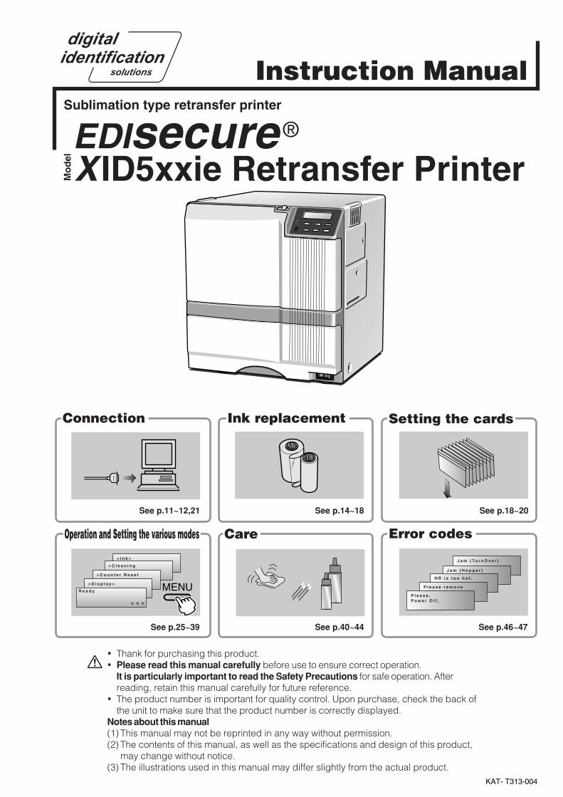
KAT- T313-004 Jam (TurnOver) Jam (Hopper) HR is too hot. Please remove MEDIA FILM Please, Power Off. >Ink> >Cleaning >Counter Reset >Display> Ready MENU Instruction Manual Sublimation type retransfer printer Error codes Setting the cards Care Operation and Setting the various modes Ink replacement Connection *** Model X ID5xxie Retransfer Printer EDIsecure ® See p.11~12,21 See p.14~18 See p.18~20 See p.25~39 See p.40~44 See p.46~47 • Thank for purchasing this product. • Please read this manual carefully before use to ensure correct operation. It is particularly important to read the Safety Precautions for safe operation. After reading, retain this manual carefully for future reference. • The product number is important for quality control. Upon purchase, check the back of the unit to make sure that the product number is correctly displayed. Notes about this manual (1) This manual may not be reprinted in any way without permission. (2) The contents of this manual, as well as the specifications and design of this product, may change without notice. (3) The illustrations used in this manual may differ slightly from the actual product.
Transcript of Model XID5xxie Retransfer Printer - Nexus | Kartendrucker ... 5xxie/Manual/XID5xxie... · Jam...
KAT- T313-004
J a m ( Tu r n O v e r )
J a m ( H o p p e r )
H R i s t o o h o t .
P l e a s e r e m o v eM E D I A F I L M
P l e a s e ,P o w e r O f f .
> I n k >
> C l e a n i n g
> C o u n t e r R e s e t
> D i s p l a y >
R e a d y MENU
Instruction ManualSublimation type retransfer printer
Error codes
Setting the cards
CareOperation and Setting the various modes
Ink replacementConnection
* * *
Mo
del X ID5xxie Retransfer Printer
EDIsecure ®
See p.11~12,21 See p.14~18 See p.18~20
See p.25~39 See p.40~44 See p.46~47
• Thank for purchasing this product.• Please read this manual carefully before use to ensure correct operation.
It is particularly important to read the Safety Precautions for safe operation. Afterreading, retain this manual carefully for future reference.
• The product number is important for quality control. Upon purchase, check the back ofthe unit to make sure that the product number is correctly displayed.
Notes about this manual(1) This manual may not be reprinted in any way without permission.(2) The contents of this manual, as well as the specifications and design of this product,
may change without notice.(3) The illustrations used in this manual may differ slightly from the actual product.

2
Declaration of Conformity
Model Number: X IDie Printeryyyyy(y=A-Z,0-9 or blank)
Product name: Card Printer
We herewith declare that the above mentioned product complies with the following council
directives and harmonized standards.
Council Directives: 1999/5/EC relating to radio equipment and telecommunications
terminal equipment.
89/336/EEC relating to electromagnetic compatibility.
2006/95/EC relating to electrical equipment designed for use
within certain voltage limits.
Harmonized Standards: EN55022:1998 Class B
EN55024:1998+A1:2001+A2:2003
EN61000-3-2:2000+A2:2005 Class A
EN61000-3-3:1995+A1:2001+A2:2005
EN60950-1:2001
EN50371:2002
EN300 330-2:V1.1.1
EN301 489-03:V1.4.1
Manufacture:
Victor Company of Japan, Limited.
2969-2, Ishikawa-cho, Hachioji-shi, Tokyo, 192-8620, Japan
Importer and distributor:
Digital Identification Solutions Group
Teckstrasse 52 , 73734 Esslingen, Germany
Year to begin affixing CE Marking: 2005
Hachioji-shi, Oct, 2007
Place, Date Tsutomu Nakama Manager-Quality Control
Victor Company of Japan, Limited.

3
NOTE: This equipment has been tested and found to comply with the limits for a Class B digital device, pursu-ant to part 15 the FCC Rules. These limits are designed to provide reasonable protection againstharmful interference in a residential installation. This equipment generates, uses and can radiate radiofrequency energy and, if not installed and used in accordance with the instructions, may cause harmfulinterference to radio communications. However, there is no guarantee that interference will not occur ina particular installation. If this equipment does cause harmful interference to radio or television recep-tion, which can be determined by turning the equipment off and on, the user is encouraged to try tocorrect the interference by one or more of the following measures:
– Reorient or relocate the receiving antenna.– Increase the separation between the equipment and receiver.– Connect the equipment into an outlet on a circuit different from that to which the receiver is con-
nected.– Consult the dealer or an experienced radio/TV technician for help.
Caution: Changes or modifications not approved by party responsible for compliance could void user's authorityto operate the equipment.
Machine noiseSound power level: less than 70dB(A) according to DIN45635 part 19 (EN27779).The measurements are to be made according to DIN45635 part 2019 or EN27779, respectively.
Information for USA
Information for EU
Information for Canada
Operation is subject to the following two conditions:(1) this device may not cause interference, and (2) this device must accept any interference, includinginterference that may cause undesired operation of the device.

4
ContentsNotes for safe operation ................................ 5Before use ..................................................... 7
Product features .................................................... 7Checking accessories............................................ 7
Handling of transfer film, ink ribbons and cards .... 7Handling ............................................................. 7Storage .............................................................. 7Storing and handling cards after printing ........... 8Purchasing print media and cards ..................... 8
Escape Clause ...................................................... 8Installation ............................................................. 9
Installation diagram ............................................ 9Names of parts ............................................ 10
Front ................................................................. 10Rear ................................................................. 10When the printer door is open.......................... 10
Set-up.......................................................... 11Connecting the IC unit (sold separately) ............. 11
Medium-type IC unit and Compact IC unit (soldseparately) ....................................................... 11
Connecting the Laminator ................................... 11Connecting the power cord.................................. 12Installing the card stacker .................................... 13
Discharging the card ........................................ 13Setting the ink ribbon ........................................... 14Setting the retransfer film .................................... 16Caution when loading the retransfer film cassetteand/or the ink ribbon cassette ............................. 18Setting cards........................................................ 18
Inserting cards ................................................. 18When using magnetic cards............................. 20When using contact IC cards ........................... 20Loading cards .................................................. 20
Switching the card thickness............................ 20Connecting with a host computer ........................ 21 USB cable connection ....................................... 21 LAN cable connection ....................................... 21
Connecting Multiple Printers ............................... 22
The copyright of the software is displayed .......... 22Before use ................................................... 23
Names of parts on the operation panel ............... 23Setting buttons ................................................. 23Operation display LED ..................................... 23LCD panel ........................................................ 23
Operation display LED contents and the LCD panel ... 24Initialization period ........................................... 24Preheating period............................................. 24
LCD operation display content ............................ 24Operation .................................................... 25
Turning on the power ........................................... 25Turning off the power ........................................... 26About the RESET button ..................................... 26On Initialization when the retransfer film cassetteand/or the ink ribbon cassette is loaded .............. 26User modes ......................................................... 27User mode screen flow ........................................ 27User mode settings.............................................. 28Display mode settings ......................................... 29Clearing the free counter ..................................... 30Cleaning mode .................................................... 30Ink mode setting .................................................. 32Retransfer mode setting ...................................... 33Buzzer mode setting ............................................ 34Power saving mode settings................................ 34Setting the bend remedy mode ........................... 35Card Thickness setting mode .............................. 36Coercivity setting mode ....................................... 36Non-contact IC antenna setting mode ................. 36IC contact setting mode ....................................... 36Test print .............................................................. 36Unit No. setting .................................................... 36Network setting .................................................... 37Input method for Address setting mode ............... 39Low temperature stand-by mode setting ............. 39Download mode................................................... 39Transport mode ................................................... 39
Care and cleaning ....................................... 40Cleaning the cleaning rollers ............................... 40Cleaning the thermal head .................................. 41Cleaning the fan filter ........................................... 41Cleaning the card feed rollers and heat rollers .... 42Cleaning the magnetic head ................................ 43Cleaning of he bobbin holders ............................. 44Once printer servicing and cleaning have beencompleted ............................................................ 44Periodical maintenance ....................................... 44
Troubleshooting........................................... 45Layout of rollers inside the printer ....................... 45Error code listing.................................................. 46Stopping when printing ........................................ 48Mending broken ink ribbon and retransfer film .... 48About printing errors ............................................ 48When retransfer operation is not complete ......... 48Caution when printing characters ........................ 48Removing card jams ............................................ 49
Hopper jam ...................................................... 49Turnover section [Jam (turnover)] .................... 50
Retransfer section [Jam (transfer)] .................. 50
Specifications .............................................. 51Main specifications .............................................. 51In case of disposal ............................................... 52

5
(to the next page)Notes for safe operationBefore you use
Read these notes on safety thoroughly before operating your printer in order to use the unit properly. Once youstart using the unit, this manual should be put aside the unit, or at a convenient place where you can look up the
manual any time as you need.
WARNING
WARNING CAUTION� If you ignore the warning with this mark, and handle
the unit in a wrong way, death or serious injuries mayoccur.
� If you ignore the caution with this mark, and handlethe unit in a wrong way, injuries or damages toproperties may occur.
� If the abnormal phenomena as listed below are seen,immediately stop operating the unit. Continuingoperation may cause a fire or electric shock.
• Smoke or odd smell comes out from the machine.• Water or metal went into the machine.• The unit fell to the floor, or the cabinet was broken.• The power cable is damaged (exposed lead, broken cable,
etc.)If you see these phenomena, turn off the power, pull out thepower plug, and contact your dealer as soon as possible. Donot try to repair it by yourself. It is dangerous.
� Do not remove the screws, or disassemble or alterthe machine.
• High-voltage components are contained in the unit.Touching these areas may result in an electric shock.
• Ask your dealer if you want your printer inspected orrepaired.
• Do not remove the external covers of the machine. You mayget an electric shock.
� Do not work on the power cable, or give excessiveforce on it. Do not put heavy objects such as furnitureon the cable.
• The cable may be damaged, causing a fire or electric shock.• When you find a defect on the power cable, such as
exposed lead, stop using the unit, and consult your dealer.
� Do not use the machine with the power plug insertedincompletely.
• The machine generates heat due to incomplete contact,causing a fire or electric shock.
• Do not put many cords on a single plug socket. The powercords also heats up.
� Do not use the machine with dusts piled on thepower plug. Do not put a metallic material adjacent tothe power plug.
• Dusts and metal are conductive, causing a fire or electricshock.
• Pull out the power plug from the outlet every six months, andclean the dusts piled on the legs and body of the plug.
� Do not use a line voltage other than instructed.• Using a line voltage or power supply which is not specified
may cause a fire or electric shock.
� Do not put foreign materials from the openings of themachine (e.g., vents, card slots, cassette inlet, etc.)
• Metals, flammable things, and other foreign materials maycause a fire or electric shock if entering into the machine.
• If these things went into the machine, immediately turn offthe power, pull out the power plug, and ask your dealer torepair. Do not try to repair it by yourself. It is dangerous.
� Do not put a container with liquid in it, or small metalornaments and the like on the machine.
• The liquid or metal entering into the machine acts as aconductor, causing a fire or electric shock.
• If liquid or metal went into the machine, immediately turn offthe power, pull out the power plug, and ask your dealer torepair. Do not try to repair it by yourself. It is dangerous.
� Do not place the machine on a rickety table orslanting places.
• The machine may fall out of the table or fall over, which maydamage the machine or injure you.
• If the machine is damaged by falling or turnover,immediately turn off the power, pull out the power plug, andask your dealer to repair. Do not try to repair it by yourself. Itis dangerous.
� Do not wet the machine with water.• Using the machine at a place where water splashes on the
machine, or wetting the machine with water (applying,throwing, or spilling water over the machine) may cause afire or electric shock.
• If water entered into the machine, immediately turn off thepower, pull out the power plug, and ask your dealer to repair.Do not try to repair it by yourself. It is dangerous.
� Do not touch the machine with wet hands.• Touching the machine with wet hands may cause an electric
shock.
� Do not touch the power plug during electrical storms.• Lightning may cause an electric shock.

6
Notes for safe operation (continued)
� Pull out the power plug before cleaning the machine.• This is for preventing electric shocks.
� Pull out the power plug when you won’t use themachine for a prolonged period of time to assuresafety.
• Remove the power plug from the outlet for safety when youwon’t use the machine for a long time.
� Do not move the machine with the power cable andother electric cables connected.
• The cables may be damaged while being moved, which maycause a fire or electric shock.
• You may stumble over the cable and get injured.
� Do not move the machine with objects placed on it.• They may fall on you and hurt you.
� Do not put heavy objects on the machine.• They may fall on you and hurt you.
� Do not block the vents.• Heat generated inside the machine cannot escape, which
may cause a fire.
� Be sure to work with two persons when you unpack,move or lift the machine.
• If you work alone, you may be injured by the fallen machineor hurt your back by lifting a heavy machine by yourself.
� Inspection• Ask you dealer or a qualified person to inspect the machine,
typically once every two to three years. Operating themachine with dusts piling on the components for a prolongedperiod of time may cause a fire or a malfunction of themachine. It will be particularly effective to inspect themachine before wet rainy season. Consult your dealer onthe costs of inspection.
� Do not put the machine at a place where it will bewet with steam (e.g., from a humidifier), or at aexcessively humid or dusty place.
• The oil, water and dusts act as conductors, which maycause a fire or electric shock.
CAUTION
� Ground the machine with the attached electric cordwhen connecting it to the utility outlet.
• Using a cord other than the one supplied for grounding maycause an electric shock when the machine fails.
� Do not put your head or yourself into the packagingbag.
• Do not play with the packaging bag. You may suffocateyourself.
• Give close attention to small children who may want to playwith the packaging bag.
� Do not use the machine while it has a fault.• Do not use the machine while it has a fault, as this may
cause a fire or electric shock.• Immediately turn off the power, pull out the power plug, and
ask your dealer to repair. Do not try to repair it by yourself. Itis dangerous.
� Do not use the power supply code of the attachmentexcluding this machine.It may cause a fire or electricshock.
� Do not put the machine at a place where it becomesexcessively hot.
• The surface and internal components may deteriorate. Alsothere is a danger of a fire. Special care should be taken forexposure to direct sunlight or a heater adjacent to themachine.
� Hold the body of the power plug when pulling it out.• Do not pull out the plug by holding the cable. The cable may
be broken or damaged which may in turn cause a fire orelectric shock.
� Do not touch the power plug with a wet hand• You may get an electric shock.
� Do not lay the power cable near the heatingequipment.
• The covering of the cable will melt due to heat from suchequipment, which may cause a fire or electric shock.
� The heat rollers and adjacent areas become hotduring operation.
• Be careful not to touch the heat rollers and adjacent areaswhen replacing the ink ribbon or retransfer film, or removejammed cards.
• Wait until the heat rollers get cooled down to prevent burns.
�Be careful of jamming your hand or fingers in the cardtray, card bracket on the hopper, or printer door.
• Replace the ink ribbon or retransfer film, or remove jammedcards with care not to jam your hand or fingers in themechanism, which may cause an injury.
� Do not use a power cable other than the specifiedcable for connection.
• If you use an unspecified power cable for connection orextension, heat may accumulate in the cable, causing a fire.
7
(to the next page)Before use
Product features
• This card printer allows printing of high-quality, fullcolor images equivalent to photographic quality ontostandard size (ISO 7810 compliance) plastic cardsusing sublimation type transfer printing.
• Use of sublimation type retransfer printing enablesprinting of cards other than those made of PVC andnon-contact IC cards, etc. with uneven surfaces thatwere previously difficult to print directly.
• Printing with no margins on all sides is possible.• This printer have more securer erase function
(security erase) to protect of the individualinformation.
• The host interface utilizes USB mode and Ethernetmode.
• This printer can automatically discern what type of inkribbon is installed by means of RF-ID tag built inside.
Checking accessories
Please check for any missing accessories whenopening the box.• AC 120V type(For North America) · · · · · · · 1unit
AC 200V type(For Europe) · · · · · · · · · · · · 1unit
• Instruction manual : English · · · · · · · · · 1 unit
* The detached power cords and the Instructionmanual vary according to model and country ofpurchase.
• Cleaning card : 1 unit
• Card stacker : 1 unit
• Ink ribbon cassette : 1 unit
• Retransfer film : 1 unitcassette
• USB Cable (200cm) : 1 unit• Jog lever (inside the card tray)
: 1 unit• Gloves : 1 unit
Some card materials may not be suitable for printing. Consultyour dealer regarding the materials to be used andspecifications required before purchase.
Handling of transfer film,ink ribbons and cards
Handling
Take note of the following points when handling printmedia (retransfer film and ink ribbons) and cards.
• Use of bent or damaged cards may result in card feederror.
• Do not touch the print media or the printed surface ofcards directly with the hands as this may cause blurringof the print.
• Foreign materials on the printing area may result inmisprints. Always load the print media and cards in aclean environment.
• Static build-up in the print media or cards can causeerrors. To avoid causing static electricity, do not rubcards together.
• When replacing or replenishing print media or cardsthat have been stored at low temperature, let the printmedia or cards sit for at least one hour at the sametemperature as location where the printer is to be usedbefore use. Using print media or cards as they are maycause condensation and result in malfunction or printerrors.
Storage
The storage condition of the print media (retransfer filmand ink ribbons) and cards may have a strong influenceon the print quality. Select a storage location that fitsthe following criteria:
Storage environmentStorage temperature : 5°C to 25°C
Storage environment relative humidity : 40% to 60%
Storage locationTo avoid deterioration of the ink ribbon and retransferfilm, do not store in the following locations:
• Locations exposed to direct sunlight• Locations with high temperature and high humidity• Locations near organic solvents or diazo copiers.
Storage periodPrint media should be used within a half year ofpurchase. For cards, please consult the dealer fromwhich they are purchased.

8
Before use (continued)
We can accept no liability for anyproblems arising as a result of the use of media usingmaterials other than those specified.
Card materialISO/IEC 7810 type ID1 (dimensions) :
equivalent productISO/IEC 7811-2 (Magnetic stripe) :
equivalent productISO/IEC 7816 (IC card) : equivalent product
The materials of some cards may not be suitable forprinting. Consult your dealer regarding the materials tobe used and specifications required before purchase.
CAUTION
�Version upgrade
The following defects may occur as a result of the
version upgrade for the firmware of the printer or
for the printer driver.
• Card printing is disabled for the application software that
has been used.
• The operation of the printer or application software
becomes unstable.
• Defects in print result occurs.
• Print color or shade differs.
• The performance of reproducing fine letters, changes.
• Others
Be sure to retain a copy of the current version when
performing version upgrade. Reinstall the previous
version immediately if these problems occur. We
are not liable for any damage such as defective
cards or interruptions during printing as a result of
the version upgrade.
Escape Clause
We do not provide compensation for any malfunctionduring card printing caused by breakdown of themachine, ink ribbon defects or card characteristics.In addition, we also do not provide compensation forinsufficient print quality, which are not agreed in
advance. Please evaluate carefully beforehand.
�Card MaterialSome card material may not be suitable for printing.Using a contact-type IC card other than those specifiedby the dealer, may cause damage to the thermal head.No compensation is made for the life reduction andfailures that were caused by unsuitable card material.Warp of card or uneven thickness of IC cards, eventhough they are within the tolerance of JIS or ISOstandards, may not be suitable for printing or feeding.For details on the specifications about card material
or others, consult the dealer in advance
Storing and handling cards after printing
Avoid storing the cards in locations exposed to directsunlight or with high temperature and high humidity.Furthermore, avoid contact with the following chemicalsand stationery, as they can cause discoloration orfading of the cards:
• Organic solvents such as alcohol, film cleaner, diazocopies, etc.
• Soft vinyl chlorides, document cases, pass holders,erasers, etc.
• Hair-dressing products and cosmetics, etc.
Purchasing print media and cards
Contact your dealer regarding the purchase of printmedia (retransfer film and ink ribbons) and cards.Always use the products specified below.
Print mediaUse only the ink ribbons and retransfer film specifiedfor this unit. For the names of these products refer to“Main Specifications” on p. 51 of this manual.

9
Installation
The performance of the card printer is stronglyinfluenced by the installation location.Be careful of thefollowing items as for installation location.
• Install in the locations is not so much as to cause printdefect due to dust adherence.Dusty environment increases print defect. It isrecommended that the card printer is used in thelocations with the cleanness Class 8 or better ofISO14661-1. But at least avoid the following locations.(1) Carpeted room(2) Crowded locations(3) Locations where paper(corrugated etc.) is handled(4) Areas near copy machinesWhen the card printer is not used, it is recommendedthat the power is turned off and the printer is coveredby plastic sheet etc.(not textile).
• Install in the locations where the printer performance iskept.Avoid the locations below where the performance or lifeof the printer is affected.(1) Locations where there is vibrations or shock(2) Locations exposed to direct sunshine.(3) Wet locations without ventilation(4) Unstable locations and sloped surface(5) Areas near air conditioners, humidifiers, stoves, etc. that may cause condensation within the printer .
• Install in the environment that gives full play to theprinter ability.
The printer is to be installed in an environmentwith the following temperature and humidity.
Temperature : 15°C to 30°C59°F to 86°F
Humidity : 35% to 70%
Use of the printer in an environmentwith temperature lower than the above range may causeretransfer errors and use of the printer in an environmentwith temperature higher than the above range may causeprint errors from deformation of the cards and wrinkling ofthe film.
CAUTION
Installation diagram
Ventilation holes are provided for the cooling fan on thebottom and sides of the unit. Avoid inserting any objectinto the gap between the bottom of the unit and the topof the stand. Install the unit with its sides at least 20cmaway from the surrounding wall as illustrated in thediagram, and keep the back of the unit at least 10cmaway from the wall. Also, do not place any object on topof the unit.
Do not place objects on top
20cm or more7.9 inches or more
20cm or more7.9 inches or more
10
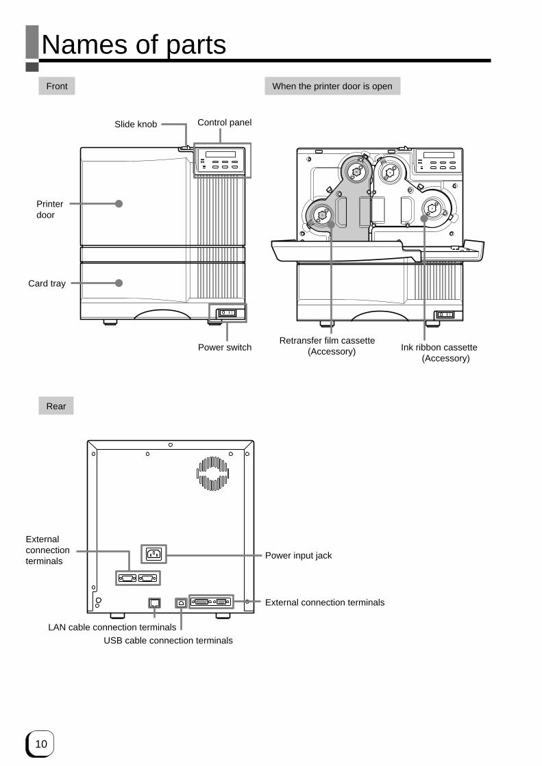
Names of partsFront When the printer door is open
Slide knob Control panel
Printerdoor
Card tray
Power switchRetransfer film cassette
(Accessory) Ink ribbon cassette(Accessory)
Rear
Externalconnectionterminals
Power input jack
External connection terminals
USB cable connection terminals
E LAN cable connection terminals

11
(to the next page)
Connecting the IC unit(sold separately)
Medium-type and compact size IC units are soldseparately, as are specialized optional devices for theprinter. Consult your dealer for more details.
WARNING• Make sure that the power switch is turned
OFF and the AC cable is detached fromthe plug, before connecting anddisconnecting the IC units. Otherwiseelectric shocks, fires or malfunction of theproduct may occur.
• Using IC units other than those specifiedmay cause electric shocks, fires ormalfunction of the product.
Electricshock
Set-up
Medium-type IC unit and Compact IC unit (sold separately)
Please ask your dealer for the Compact IC unitconnection.Connect the compact IC unit to the host computer withthe interface cables which are commercially available.The medium-type IC unit has various type of interfacecable, according to installed IC unit. Consult your dealerfor more details.
Interface cable(Commercial item)
Medium-type IC unit andCompact IC unit
1. Set up the unit joint plate which comes with thelaminator (optional). Mount the printer on to jointplate.
FRONT
FRONT
XIDieprinter
Joint Plate
The laminator is sold separately, as a specializedoptional device for the printer. Consult your dealer formore details.
WARNING• Make sure that the power switch is turned
OFF and the AC cable is detached fromthe plug, before connecting anddisconnecting the laminator. Otherwiseelectric shocks, fires or malfunction of theproduct may occur.
• Using laminator other than those specifiedmay cause electric shocks, fires ormalfunction of the product.
Connecting the Laminator
Electricshock

12
Connecting the power cord
1. Check the plug.
• For AC 120V type • For AC220-240V type (North America) (Europe)
* The detached power cords vary according to modeland country of purchase.
2. Plug the power cable into the printer.
Plug the power cable of the laminator if it is installed.
Always use a grounded power outlet.Never share the outlet with other electrical equipment.
Use an AVR (Automatic Voltage Regulator) if thereis a possibility of voltage fluctuation. Use anuninterruptible power source rather than an AVR ifthere is the possibility of uninterruptible powersource.
CAUTION
Set-up (continued)
CAUTION
Laminator(ILU)
2. install the laminator
Be careful not to pinch your finger when installing.
Memo
If the mounting is uneven, the card would not betransported smoothly. be sure to fit the units rightin. Always install the unit at a horizontal and hardsurface location
9 pin
9 pinConnecting cable
Tight the screw after connecting
OPTION2
PRINTER
CAUTION
Make sure to tighten the screws of the interface cables.
3. Install the unit connecting cable.(optional)
As shown in the diagram, connect the cable to theOPTION 2 external connection terminal of the printerand the PRINTER external connection terminal of thelaminator.

13
(to the next page)
Card dischargeslot
Claw
Card stacker(accessory)
Card stackerreceptacle
Installing the card stacker
Hang the stacker claw on the stacker receptacle.
The card stacker is capable of containing approximately100 0.76mm(0.03inches)-thick cards or 300 0.25mm(0.01inches)-thick cards at the maximum.
Be sure to hang the card stacker clawon the card stacker receptacle, not the card dischargeslot. If you mount the card stacker at a wrong place,cards are not discharged, resulting in a card jam.
CAUTION
Discharging the card
When correctly printed, the cards are discharged fromthe left side.If a card jam or a write error on magnetic stripes occurson the way, results differ depending on the areas.
Portion A: If a card jam , a write error on magneticstripes or an IC unit encode error occurs onthe way, press the RESET button, then theENTER button. The printer is initialized,and the cards are discharged from the rightside of the printer.
Portion B: See the description in Jam (Transfer) onp.50.
Portion C: When correctly printed, the cards aredischarged from the left side of the printer.The cards jamming around this area arealso discharged from the left side.
C B A
Retransfer film cassette Ink ribbon cassette
Thermal headMagnetic headCard turnover tableFeed roller
NG carddischarge slot
Cleaning unit
Card feed roller
Retransfer roller (heat roller)Bent remedial roller (heat roller)
Card discharge slot
Card stackerreceptacle
Claw
Card Stacker(accessory)
When connecting the laminator, pull the tab of the cardstacker at the stacker mount of the laminator card.
14
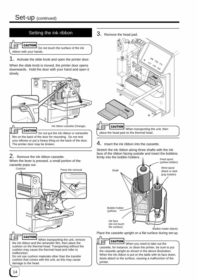
4. Insert the ink ribbon into the cassette.
Stretch the ink ribbon along three shafts with the inkface of the ribbon facing outside and insert the bobbinsfirmly into the bobbin holders.
Place the cassette upright on a flat surface during set-up.
Setting the ink ribbon
Do not touch the surface of the inkribbon with your hands.
1. Activate the slide knob and open the printer door.
When the slide knob is moved, the printer door opensdownwards. Hold the door with your hand and open itslowly.
Do not put the ink ribbon or retransferfilm on the back of the door for mounting. Do not restyour elbows or put a heavy thing on the back of the door.The printer door may be broken.
2. Remove the ink ribbon cassette.When the lever is pressed, a small portion of thecassette pops out.
When transporting the unit, removethe ink ribbon and the retransfer film, then place thecushion on the thermal head. Transporting without thecushion may cause the thermal head and roller tomalfunction.Do not use cushion materials other than the transfercushion that comes with the unit, as this may causedamage to the head.
CAUTION
Set-up (continued)
CAUTION
Press the removallever.
Ink ribbon cassette (Orange)
CAUTION
Shaft
Ink face(do not touchthe surface)
Bobbin holder (black)
Wind spool(black or darkgray bobbin)
Feed spool(yellow bobbin)
CAUTION
Cushion
When you need to take out thecassette, for instance, to clean the printer, be sure to putthe cassette upright as shown in the above illustration.When the ink ribbon is put on the table with its face down,dusts attach to the surface, causing a malfunction of theprinter.
Bobbin holder(yellow)
3. Remove the head pad.
REMOVE..........
..........<For Transport Only>
Remove the pad
..............<For Transport Only>
CAUTIONWhen transporting the unit, then
place the head pad on the thermal head.
15
(to the next page)
6. Insert the cassette along the guide rail.
Insert the cassette until it clicks securely into position.The lever returns to its original position.
• The cassette containing the inkribbon is heavy. Hold the cassette with both handswhen you set or take out the cassette.
• If the cassette unit is not inserted until it clicks securelyinto position before printing, horizontal lines may beprinted with the image.
Guide rail
CAUTION
I n k R u n O u t
I n k S e a r c h
I n k B r o k e n
Memo
When the ink ribbon is wound up to the end,
appears on the LCD panel.After replacement press the RESET button, thenpress the ENTER button.If the ink ribbon is not set properly,
or
appears on the LCD panel. When these messagesare output, check:• The ink ribbon is firmly inserted into the bobbin
holders.• The ink face of the ribbon is directed correctly.• The feeding and winding bobbins are mounted
correctly.
Memo
To mount the ink ribbon which is partially used, setthe unused portion of the ribbon (yellow bobbin) onthe bobbin holder indicated with an arrow on the sealof the cassette.Printing with the ink ribbon set improperly may causethe image to be faint.
7. Close the printer door.
If you want to mount the retransfer film, keep the dooropen and go to the next page.
CAUTION
5. Wind the ribbon, taking up the slack.
Turn the knob in the arrow direction to wind a smallportion of the ink ribbon. If the ink ribbon does not windup, go back to step 3, and insert the ink ribbon firmlyinto the bobbin holders.
If the ink ribbon is not tightly wound,the slack may cause the ribbon to be caught in the partsof the printer when you set the cassette, or the card to beprinted in uneven colors.

16
Set-up (continued)
Setting the retransfer film
Do not touch the retransfer filmsurface with your hands.
1. Activate the slide knob and open the printer door.
When the slide knob is moved, the door opensdownwards. Hold the door with your hand and open itslowly.
Do not put the ink ribbon or retransferfilm on the back of the door for mounting. Do not restyour elbows or put any heavy object on the back of thedoor as it may break.
2. Remove the retransfer film cassette.
When you press the lever, a small portion of thecassette pops out.
CAUTION
Press the cassetteremoval lever.
3. Insert the retransfer film into the cassette.
Stretch the retransfer film along three shafts with theretransfer face of the film facing outside and insert thebobbins into the bobbin holders firmly.At this time, perform setting so that the film is inside theguide. Wind the film to the wind spool more than threestripes (two frames).Otherwise the printer may fail.
Place the cassette upright on a flat surface during set-up.
When you need to take out the cassette, for instance, toclean the printer, be sure to put it upright as shown in theabove illustration. When the film is put on the table withits retransfer face down, dusts attach to the surface,causing a failure of the printer.
Retransfer film cassette (yellowishgreen)
CAUTION
CAUTION
Shaft
Bobbin holder (green)
Retransfer face(do not touch thesurface)
Feed spool (greenbobbin)
Wind spool(black bobbin)
Bobbin holder (black)
Wind the film by aboutthree stripes (two frames)on the winding bobbin.
One frame
Guide
Black stripes

17
(to the next page)
4. Wind the retransfer film to take up the slack.
Turn the knob in the arrow direction to wind a smallportion of the retransfer film. If the film does not windup, go back to step 3, and insert the bobbins firmly intothe bobbin holders.
If the film is not tightly wound, theslack may cause the film to be caught in the parts of theprinter when you set the cassette, or damaged due towrinkles on the film. At this time, do not hold the film toremove slack. Winding deviation causes operation errorsor defective prints.
5. Open the printer door and insert the cassette.
Insert the cassette until it clicks securely into position.The lever returns to its original position.
The cassette containing the retransferfilm is heavy. Hold the cassette with both hands whenyou set or take out the cassette.
CAUTION
6. Setting the number of frames to be used.
The number of frames of the retransfer film being usedis set.For details, refer to the “Media Type” setting on page33.This work must be done when the used film (number offrames) is changed.
When the setting of number of framesis not correct, the printed picture may be entirely shiftedon the card.
7. Close the printer door.
CAUTION
M e d i a R u n O u t
M e d i a S e a r c h
M e d i a B r o k e n
Memo
When the retransfer film is wound up to the end,
appears on the LCD panel.After replacement press the RESET button, thenpress the ENTER button.If the retransfer film is not set properly,
or
appears on the LCD panel. When these messagesare output, check:• The retransfer film is firmly inserted into the bobbin
holders.• The retransfer face of the film is directed correctly.• The feeding and winding bobbins are mounted
correctly.
Memo
To mount the retransfer film which is partially used,set the unused portion of the film on the bobbinholder indicated with an arrow on the seal of thecassette.Printing with the transfer film set improperly maycause the image to be faint.
CAUTION

18
Set-up (continued)
Setting cards
Please use cards specified by your dealer. This unit cantake both 0.76 mm(0.03inches)-thick and 0.25 mm(0.01inches)-thick cards. The factory setting is for 0.76mm-thickness.
Fingerprints, soiling, etc. on card surface can result inprint errors. Wear lint-free gloves when handling.
CAUTION
Caution when loading the retransfer filmcassette and/or the ink ribbon cassette
The following caution shall be kept when the retransferfilm cassette and/or the ink ribbon cassette is removedbecause of card jam or other trouble.
Please pay enough attention so that the retransfer filmand/or ink ribbon is maintained at the right position.Particularly, the ink ribbon is extremely thin, therefore itapt to slip down when the cassette is removed asshown in the illustration.
When loaded in this condition, it may cause improperprinting such as INK RUNOUT error, improper colorprinting etc.To avoid this, please handle the ink ribbon and/or theretransfer film very carefully with hands so that themedia position of take-up side become parallel.Please do not touch the print side of the ink ribbon and/or the retransfer film with your hands. Otherwise, it maycause improper printing.When adjusting the print position of the retransfer filmand/or ink ribbon, please follow the instruction labelattached on the cassettes.
Improper Winding
Adjust the position with hands so
that the media position of take-up
side and supply side becomes parallel
Inserting cards
The unit can take about 300 0.76mm-thick cards.As for 0.25mm thick cards do not insert more than 300pieces.
When removing new cards from thebox, it is possible that cards may be stuck due to staticelectricity. In this case, peel the cards off one at a timebefore setting into position. Hold the edges of the cardwhen carrying out these operations.
1. Open the card tray.
Hold the lower part of the card tray and pull the traytoward you slowly until it no longer moves.
CAUTION
This 300 pieces is not a guaranteed quantity.In the event of card feed failure, caused by card bending or others reduce card quantity.
19
(to the next page)
4. Close the card tray.
Push the card tray back into the printer until it no longermoves.
CAUTION
2. Pull the card bracket back.
The card bracket locks when it reaches the hole.
3. Insert the cards and move the bracket back intoposition.
Limit the number of cards as the card bracket movesback slightly from the lock position.
Setting the cards improperly cancause feed jams. Check that the cards are neatlyarranged.
CAUTION
CAUTION
Align the cardsneatly with theside
Be sure that thetops of the cardsare alignedproperly
CAUTIONWhen handling cards, avoid dusty
environment and use the attached gloves.Dusty cards such as those finger marked may causeimproper printing.Consult your dealer to purchase new gloves.
When moving the card bracketback into position, do this slowly to avoid jammingyour fingers. Leaving the card bracket out of positionmay cause card jams.
To print pre-printed cards on thisprinter, determine print layout, color tone and cardinserting direction by in advance consulting yourdealer.Especially for card pre-printed in a dark color suchas black, card positioning error may happen.And for a magnetic or IC card, encoding error mayhappen.

20
Loading cards
Load cards when the printer’s LCD panel shows themessage “Ready” or “No Card”, and not when printeroperations have stopped due to an error. Cards canalso be loaded when the power supply is not switchedon. If there is a drop in the volume of remaining cards(under about 25 cards with a thickness of 0.76mm), theelectronic beep sounds before every feeding.(See p.34 in this manual.)
When “Loading” is displayed on the LCD panel, donot open the card tray under any circumstances.The unit is currently feeding cards. If a messageother than the one above is displayed, cards can beloaded even while the unit is printing. However, youare recommended to load cards when the unit is notprinting.
To prevent defective printing caused bysuspended printing or vibration as a result ofopening and closing the card tray, load cardswith care.
R e a d y N o C a r d
OR
L o a d i n g
When using magnetic cards
When using cards with magnetic strips, set the cards inthe following manner.
For JIS II cards:
Place the card with its magnetic stripes upward andfacing the card bracket.
For ISO cards:
Place the card with its magnetic stripes downward andfacing the card bracket.
Printing on cards with magnetic stripsis not guaranteed.
When using contact IC cards
When using contact IC cards, set in the followingmanner.
CAUTION
Place the IC card with its ICterminal inward and facing the cardbracket.
Switching the card thickness
Depending on the material, some 0.25mm(0.01inches)thick cards may not be suitable for printing. Consultyour dealer regarding the materials and specificationsof the card before purchasing.
WARNING• As for switching the card thickness,consult
your dealer or the service personnel. Otherwise injuries or malfunction of the
printer may be caused
Injury
Electric shock
Set-up (continued)
21
(to the next page)
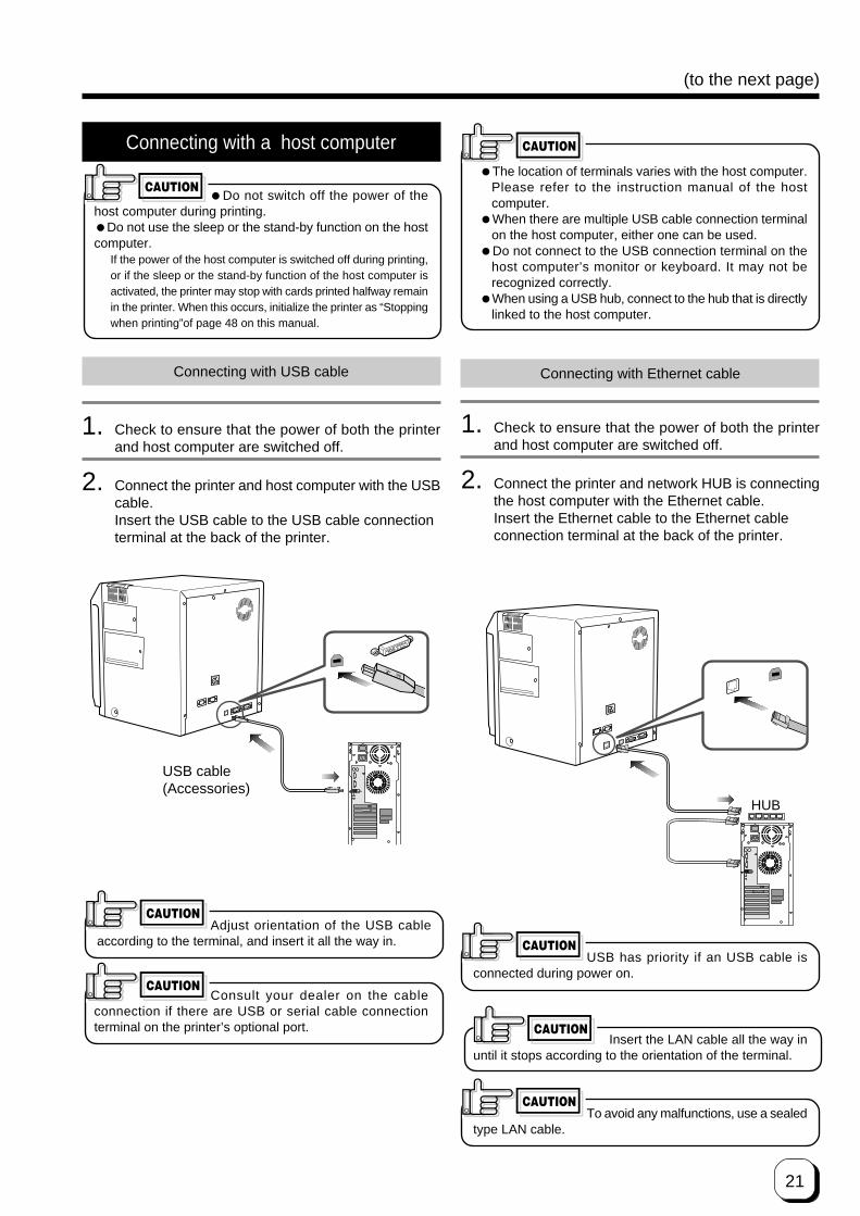
Connecting with a host computer
�Do not switch off the power of thehost computer during printing.�Do not use the sleep or the stand-by function on the hostcomputer.
If the power of the host computer is switched off during printing,or if the sleep or the stand-by function of the host computer isactivated, the printer may stop with cards printed halfway remainin the printer. When this occurs, initialize the printer as “Stoppingwhen printing”of page 48 on this manual.
1. Check to ensure that the power of both the printerand host computer are switched off.
2. Connect the printer and host computer with the USBcable.Insert the USB cable to the USB cable connectionterminal at the back of the printer.
CAUTION
Adjust orientation of the USB cableaccording to the terminal, and insert it all the way in.
Consult your dealer on the cableconnection if there are USB or serial cable connectionterminal on the printer’s optional port.
�The location of terminals varies with the host computer.Please refer to the instruction manual of the hostcomputer.
�When there are multiple USB cable connection terminalon the host computer, either one can be used.
�Do not connect to the USB connection terminal on thehost computer’s monitor or keyboard. It may not berecognized correctly.
�When using a USB hub, connect to the hub that is directlylinked to the host computer.
CAUTION
CAUTION
CAUTION
USB cable(Accessories)
Connecting with USB cable Connecting with Ethernet cable
HUB
1. Check to ensure that the power of both the printerand host computer are switched off.
2. Connect the printer and network HUB is connectingthe host computer with the Ethernet cable.Insert the Ethernet cable to the Ethernet cableconnection terminal at the back of the printer.
USB has priority if an USB cable isconnected during power on.
CAUTION
Insert the LAN cable all the way inuntil it stops according to the orientation of the terminal.
CAUTION
To avoid any malfunctions, use a sealedtype LAN cable.
CAUTION

22
Connecting Multiple Printers
When connecting a host computer to multiple printers,set different Unit Numbers from 1 to 7 for each printer.Refer to see the page 36 of the instruction manual.To connect multiple printers to a network, you mustconfigure the IP addresses for a every printer, For details,see page 37 of this documentation.
The Copyright of the Software is displayed
This product includes software developed by the Open SSL
Project for use in the Open SSL Toolk i t . (h t tp : / /
www.openssl.org/)
This product includes cryptographic software written by Eric
Young([email protected]).
Th is p roduc t inc ludes so f tware wr i t ten by Tim
Hudson([email protected]).
Set-up (continued)
23
(to the next page)Before use
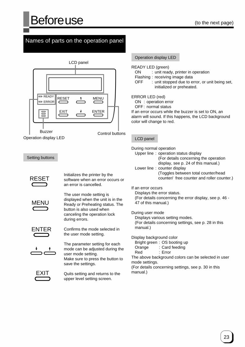
Names of parts on the operation panel
Setting buttons
RESET
EXIT
MENU
ENTER
READY
ERROR
LCD panel
Operation display LEDControl buttons
ENTER
EXIT
MENU
RESET
Operation display LED
READY LED (green)ON : unit ready, printer in operationFlashing : receiving image dataOFF : unit stopped due to error, or unit being set,
initialized or preheated.
ERROR LED (red)ON : operation errorOFF: normal status
If an error occurs while the buzzer is set to ON, analarm will sound. If this happens, the LCD backgroundcolor will change to red.
LCD panel
During normal operationUpper line : operation status display
(For details concerning the operationdisplay, see p. 24 of this manual.)
Lower line : counter display(Toggles between total counter/headcounter/ free counter and roller counter.)
If an error occursDisplays the error status.(For details concerning the error display, see p. 46 -47 of this manual.)
During user modeDisplays various setting modes.(For details concerning settings, see p. 28 in thismanual.)
Display background colorBright green : OS booting upOrange : Card feedingRed : Error
The above background colors can be selected in usermode settings.(For details concerning settings, see p. 30 in thismanual.)
Buzzer
Initializes the printer by thesoftware when an error occurs oran error is cancelled.
The user mode setting isdisplayed when the unit is in theReady or Preheating status. Thebutton is also used whencanceling the operation lockduring errors.
Confirms the mode selected inthe user mode setting.
The parameter setting for eachmode can be adjusted during theuser mode setting.Make sure to press the button tosave the settings.
Quits setting and returns to theupper level setting screen.

24
Operation display LED contentsand the LCD panel
For details, see p. 46 – 47 of this manual.
Initialization period
When the power is turned on, the printer performspositioning of the ink ribbon and retransfer film. It alsoinitializes the mechanisms of the printer and check theiroperations. “Initializing” is displayed on the LCD panelduring this period.
Preheating period
When the initialization of the mechanisms completesnormally, the printer increases the temperature of theretransfer roller and bend remedial roller up to thespecified levels. “Preheating” is displayed on the LCDpanel during this period.
LCD operation display content
Printer status
Mechanism setperiod
Preheat period
Ready period
Printer operationperiod
Error occur
User mode
READY ERROR LCD panel
Initializing..
Preheating..
Ready
When an erroroccurs*Depends on theerror content
Depends on theuser mode content
or
: LED on
: LED off
P r e h e a t i n g . .
L o a d i n g . .
P r i n t i n g . .
E n c o d i n g . .
R e t r a n s f e r . .
U n l o a d i n g . .
C l e a n i n g . .
S l e e p i n g . .
U S B R e a d y
x x x x x
x x x x x
x x x x x
x x x x x
x x x x x
x x x x x
x x x x x
H e a t i n g . .
x x x x x
N E T R e a d y
G e t t i n g I P
OS booting up
* Firmware version
Shows firmwareversion number.
Displayed during theinitializationprocess.
Displayed duringpreheating
* Displays Total/Head/Free orRoller(Display is Roll.),according to the counterselect setting.
Displayed duringfeeding
Ready status(USB connection)
* Print counter
Displayed duringprinting
Displayed duringencoding
Displayed duringretransfer
Displayed when cardsare discharged from theNG card outlet
Displayed duringcleaning operations
When the heaterstatus is OFFbecause of the powersave function
Before use (continued)
Displayed duringadjusting thetemperature forsetting value
Memo
I n i t i a l i z i n g . .
B o o t U p . .
x x x x x x x
V e r . x x x / x x / x x
I N T C o m p l e t e
x x x x x
Ready status(LAN connection)
Getting IP address(In case of DHCPON)
Network adress
When the heat roller temperature setting has beenchangeed or after setting the Low temperaturestand-by mode.HEATING will be displayed if theconfigured temperature does not match the actualtemperature before the retransfer operation starts.

25
(to the next page)Operation
Turning on the power
1. Before turning on the power, check the following:Make sure that the printer door is completelyclosed.Make sure that the card tray is completely closed.Make sure that the host computer is correctlyconnected.Make sure that any peripheral equipment iscorrectly connected.Make sure that the power supply outlet is correctlyconnected.(Power on the laminator first, if connected.)Only switch the unit on after checking the abovepoints.
2. Turn the power ON.
(I represents ON and O represents OFF.)
RESET
EXIT
MENU
ENTER
READY
ERROR
ORR e a d y P r e h e a t i n g . .
CAUTION
RESET
EXIT
MENU
ENTER
READY
ERROR
3. The unit will be in the ready status approximately 4minutes after turning on the power.
The operation display LED (READY LED) will light up.
Making settings in the user modesWhen the LCD panel displays Ready or Preheating,
press MENU
button.
For details concerning each user mode setting, see p.28 of this manual.
4. Enter the control command from the hostcomputer to print cards.
The operation display LED (READY LED) will flashwhile the unit is receiving image data from the hostcomputer.
Do not turn the power off while theLCD panel displays ‘Boot up’ to ‘Initializing’, as thismay cause malfunctions.
Be sure NOT to do any of the following during printingoperations and initialization process :• Do not open the printer door.• Do not open the card tray.
(while the LCD panel displays ‘Loading’)• Do not turn off the power supply.• Do not unplug the unit.• Do not pull out the connection cable.Failure to observe the above points will cause printingto be aborted and may result in a malfunction of theunit.

26
When the printer was occurred anerror during printing operation caused by above-mentioned operation or others, the retransfer film wasrewinded about 3 panels. If the printer is turned off and onthe power or is initialized, the printer occur the printing anerror which is “INK RUNOUT” or print results problembecause of the printer try to print the used retransfer film.Wind up the retransfer film about 3 panels by unusedpanel. See p.18 “Caution when loading the retransfer filmcassette and/or the ink ribbon cassette” and p.26 “Oninitialization when the retransfer film cassette and/or theink ribbon cassette is loaded”.
Turning off the power
1. Check the printer status.
In ready, preheat or error status, check that printeroperations are suspended.
2. Turn off the power.
Always wait 10 seconds or more before turning thepower back on again.
About the RESET button
When an error occurs in the printer, press the RESET
button, then the ENTER button.
The printer is initialized with this operation.
If the error still persists, see p.46-47 and take the
appropriate actions.
Then, press the RESET button, and the ENTER button
again. The printer is initialized, and returns to the
“Ready” state.
(When you turn off the power, these procedures are not
necessary.)
CAUTION On Initialization when the retransfer filmcassette and/or the ink ribbon cassette
is loaded
Dust or foreign particles may attach on the surface ofretransfer film and ink ribbon when their cassette areremoved from the printer.This may cause defective printing such as image void,defective retransfer etc.To Avoid this, it is recommended that the retransfer filmand the ink ribbon are wound up one or two panels afterthey are reloaded.Please follow the initialization procedure describedbelow:
1. Turn the power switch on, and wait until the LCDpanel displays “Preheat” or “Ready”.
2. Depress the RESET
key.LCD panel displays:
3. By depressing the key or the key, the
LCD panel change accordingly as shown below.Select the wind-up condition, one or two panels.(This set up is not memorized.)
• Initialized after two panels of the retransfer filmand the ink ribbon are would up.
• Initialized after one panels of the retransfer filmand the ink ribbon are would up.
• Initialized without winding up. (Default)
4. By depressing the ENTER key, the printer is
initialized according to the selected above set upcondition.
I n i t i a l i z e
O K ?
I n i t i a l i z e
2 ' n d P a n e l , O K ?
I n i t i a l i z e
N E X T P a n e l , O K ?
I n i t i a l i z e
O K ?
Operation (continued)
Turn off the power switch when you won’t use theprinter for a prolonged period of time for powersaving.

27
(to the next page)
User modes
The settings for printing media, card, etc. can be madein the User mode.
Press the MENU button when the unit isin the Ready, Preheat or Error status tosuspend printing operations.
User mode screen flow
MENU
MENUMENU
MENUMENU
MENUMENU
MENUMENU
MENUMENU
MENUMENU
MENUMENU
MENUMENU
MENUMENU
MENUMENU
MENUMENU
MENUMENU
MENUMENU
MENU
MENU
MENU
MENU
MENU
MENU
MENU
MENU
MENU
MENU
MENU
EXIT
EXIT
EXIT
EXIT
EXIT
EXIT
EXIT
EXIT
EXITEXIT
MENU
MENUMENUMENU
EXIT
MENUMENU
EXIT
MENUMENUMENU
MENU
MENU
MENUMENUMENU
MENUMENUMENU
EXIT
EXIT
EXIT
EXIT
EXIT
EXIT
> C l e a n i n g >
> I n k >
> R e t r a n s f e r >
> B u z z e r> Te s t P r i n t
> P o w e r S a v i n g
> B e n d R e m e d y >> C a r d T h i c k n e s s> M G I S O Ty p e> I C A n t e n n a P o s .
> C o u n t e r R e s e t
See P.31> D i s p l a y >
See P.30
> I C C o n t a c t P o s .
See P.36
See P.31
See P.32
See P.33
See P.34See P.36
See P.34
See P.35See P.36See P.36See P.36
U s e r M o d e
See P.39
> U n i t N o .
See P.36
> D o w n l o a d >
See P.37�
> T r a n s p o r t M o d e
See P.39
> H R C o n t r o l
See P.39
> N e t w o r k >
MENUPress and appears on the LCD panel.
After 0.5 seconds, the display will switch tothe following items.
See p. 29
See p. 35
See p. 35
See p. 35
See p. 35
See p. 35See p. 33
See p. 30
See p. 31
See p. 32
See p. 33
See p. 30
End of user mode
See p. 34
CAUTIONWhen you change settings for the
underlined submenu on the next page, (Setting theretransfer film, Setting the retransfer roller temperatureand Bend remedy roller temperature setting),the message“Please Reset” will appear on the LCD panel.Then initialize the printer by pressing
key and next key.RESET ENTER
See p. 34
28
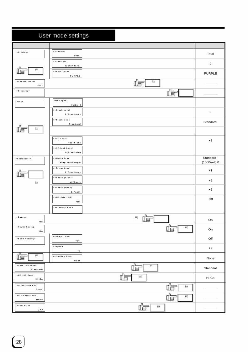
User mode settings
> B e n d R e m e d y >
> R e t r a n s f e r > > > M e d i a Ty p e
> > Te m p . L e v e l
> > S p e e d ( F r o n t )
> > S p e e d ( B a c k )
S t d ( 1 0 0 0 / r o l l ) : 0
0 ( S t a n d a r d )
+ 2 ( F a s t )
+ 2 ( F a s t )
Standard
(1000/roll):0
Standard
+1
+2
+2
Off
+2
None
0
+3
0
PURPLE
On
Standard
Hi-Co
On
Total
> > Te m p . L e v e l
> > S p e e d
> > C o o l i n g T i m e
O f f
+ 2
N o n e
> I n k >> > I n k Ty p e
> > B l a c k L e v e l
Y M C K : 0
0 ( S t a n d a r d )
> > B l a c k M o d e
> > U V L e v e l
S t a n d a r d
+ 3 ( T h i c k )
> > S P - I n k 2 L e v e l
0 ( S t a n d a r d )
> D i s p l a y >
> P o w e r S a v i n g
> > C o u n t e r
> > C o n t r a s t
> > B a c k C o l o r
To t a l
0 ( S t a n d a r d )
P U R P L E
> C l e a n i n g >
> C a r d T h i c k n e s s
> M G I S O Ty p e
> B u z z e r
> C o u n t e r R e s e t
O n
S t a n d a r d
H i - C o
O n
O K ?
�
�
�
�
�
�
�
�
�
�
> I C A n t e n n a P o s .
N o n e�
> I C C o n t a c t P o s .
N o n e�
> Te s t P r i n t
O K ?
�
> > M G P r i n t ( J I S )
O f fOff
> > S t a n d b y m o d e
= = F r o n t W a i tFront Wait
0
Upper Right> > U V M A C A d r P o s
U p p e r R i g h t
Main menu Submenu Factory setting
Display mode
Ink mode
Retransfer mode
Bend Remedymode
4 counter type settings: [Total, Head, Free, Rollers]
LCD panel contrast setting: 7 gradations from –3 to +3, the higher the value the stronger the contrast.
LCD panel background color setting: 8 optionsSee p. 30
See p.32
See p. 33
See p. 31
See p. 31
See p. 34
See p. 34
See p. 36
See p. 36
See p. 36
See p. 36
See p. 36
Counter reset modeFor free counter resetting: press the ENTER button.Cleaning modeFor cleaning mode setting: Magnetic head and card feeder roller execution
Display on ink ribbon : the ink type being used is displayedDisplay only because of automatic setting by RF-ID(Setting is not possible)
Setting the black level K: 9 gradations can be set from –3 to +5, thelarger the value the darker the printing.
Setting the K printing mode: 2 options [standard and fine]
Setting the retransfer film: setting the film type[1000,750] - two types
Setting the retransfer roller temperature:6 gradations can be set from –3 to +2,the larger the value the higher thetemperature.
Setting the retransfer speed: 13 gradations can be set from –10 to +2,the larger the value the faster the speed.
Setting the rear retransfer speed: 13 gradations can be set from –10 to +2, thelarger the value the faster the speed.
Buzzer modeSetting the buzzer ON/OFF: 2 settings [on and off]
Power saving modeSetting the time for the power saving mode:9 options [off, 5, 10, 15, 20, 25, 30, 45 and
60] (units: minutes)Bend remedy roller temperature setting: 7 gradations can be set from –5 to 0 or
off, the larger the value the higherthe temperature.
Bend remedy speed setting: 5 gradations can be set from –2 to +2, thelarger the value the faster the speed.
Cooling time setting: 16 gradations can be set: none and 1–15 (unitsseconds).
Card thickness setting mode:Card thickness setting: 2 options [Standard, Thin]
Coercivity setting mode:ISO card coercivity setting: 2 options [Lo-Co
and Ho-Co]Non-contact IC antenna setting mode:Non-contact IC antenna position setting: 3 options [None, Ext. Unit, Added on]
IC contact position setting mode:IC contact position setting: 3 options [None, Built-in, Ext. Unit]
Test print mode:to carry out test printing: press the ENTER button.
Setting the special ink SP-Ink2 level:9 gradations can be set from –3 to +5, the larger the value the darker the printing.
Setting the way of peeling off the retransfer film: 2 settings [On and Off]
Laminate Standby selection: In case of both side printing with optional unit connected,select either one of the card sides for standby.2 Settings [Front Wait, Back Wait]
Operation (continued)
See p. 35
UV ink level setting: 9 levels of density setting –3 to +5, thelarger the value the darker the printing.
Setting of MAC address position in the case of UV print [Upper Right, Lower Left]

29
(to the next page)
> T r a n s p o r t m o d e
O K ?
LAN
On
PRINTER01> N e t w o r k > > > P r i n t e r N a m e
> > H o s t I n t e r f a c e
> > D H C P
P R I N T E R 0 1
L A N
O n
> H R C o n t r o l
�O f f
�
�
> > I P A d d r e s s
1 9 2 . 1 6 8 . 0 . 1 4 1
> > S u b n e t M a s k
2 5 5 . 2 5 5 . 2 5 5 . 0
> > G e t e w a y
1 9 2 . 1 6 8 . 0 . 1
> > S e s s i o n T i m e O u t
O f f
> > M A C a d d r e s s
= 0 0 8 0 - 8 8 4 2 - 8 B 0 0
> > I P S e c M o d e
O f f
> > I P S e c Ty p e
n o t s e t t i n g
192.168.0.141
255.255.255.0
192.168.0.1
Off
Off
not Setting
�
> D o w n l o a d >
O K ?
�
Off
> U n i t N o .
N o . 1
�No.1
Transport Mode:Transport mode setting: press the ENTER button.
See p. 36Unit No: 7 options [No.1 to No.7]Unit No. setting: press the ENTER button.
Main menu Submenu Factory setting
See p. 39
See p. 39
See p. 39
See p. 37
Printer name entry, Please select the PRINTER 01-09 and anothername is enter from the host computer (within 10 letters or numbers)
Select Interface [USB, LAN ]
Availability of DHCP. [On, Off ]
IP address settings (Setting when DHCP is Off)
Subnet Mask settings(Setting when DHCP is Off)
Default Gateway settings (Setting when DHCP is Off)Net Session Timeout Settings [Off, 10min, 20min, 30min, 60min]
Displayed of MAC address
Availability of IP Sec.[Off , On ](When IP Sec Type is “not setting”, it is fixed at Off)
Display of IP Sec authentification method not setting, Preshared(presharing of key authentication), Certificate (Public key certificate)
Low Temperature Standby mode setting[On, Off ]
Firmware Download modePress the ENTER button to enter download mode..
Network modeThe current IPaddress is displayed

30
> D i s p l a y >
> > C o u n t e r
> > C o n t r a s t
> > B a c k C o l o r
To t a l
- 2
P U R P L E
ENTER
ENTER
ENTER
MENU
MENU
MENU
EXIT
EXIT
EXIT
ENTER
EXIT
SKY BLUE, BLUE, LIGHT BLUE, GREEN, BRIGHT GREEN, YELLOW, PURPLE, PINK
Exit user mode.
Counter select mode4 options (Free, Head, Total ,Rollers)
Press to select the setting and press to save.Counter selection
• Total counter (Total)Displays the number of cards in total whichhave been printed correctly.The total counter cannot be reset.
• Head counter (Head)Displays the number of printing colors in oneHead.The head counter cannot be reset.
• Free counter (Free)This allows the user to clear the counter.Displays the number of cards which have beenprinted correctly.
• Roller counter (Rollers)
Roller counter is reset with be cleaning thisroller
LCD panel contrast setting There are 7 gradations(–3 to +3, the higher the value the stronger the contrast.)
LCD panel backgroundcolor settings:8 options
Press to select the setting and press to save.
Press to select the setting and press to save.
(The electronicbeep sounds.The beep will notsound if thebuzzer modesetting is set tooff.)
(The electronic beep sounds .Thebeep will not sound if the buzzermode setting is set to off.)
(The electronic beep sounds .Thebeep will not sound if the buzzermode setting is set to off.)
Operation (continued)
Display mode settings
The unit has the following three settings for the displaymode. Allows selection of which counter value isdisplayed when the power is turned on.
CAUTION• The beep sounds when pressing the
Enter button to save the settings in the user setting mode.• The beep will not sound if the buzzer mode setting (see
p.34) is set to off.

31
(to the next page)
Clearing the free counter
Reset the free counter.The [Total] counter and [Head] counter cannot be reset.
Cleaning mode
The printer is provided with an operation mode forcleaning the card feed roller and the magnetic head tokeep the printer in the best condition.See p.42,43 and p.44 for executing the cleaning mode.
> C o u n t e r R e s e t
O K ?
EXIT
ENTER
Exit user mode.
Press to reset.(The electronic beepsounds .The beep will not sound if the buzzer mode setting is set to off.)
To check that the counter is reset to zero, select “FreeCounter” in “Setting the counter type” on p.29.
CAUTIONThe head counter is cleared to zero
each time the thermal head is replaced.
> C l e a n i n g >
> > R o l l e r s
O K ?
> > MG H e a d
O K ?
ENTER
ENTER
ENTER
ENTER
Execution (The electronic beep sounds.The beep will not sound if the buzzer mode setting is set to off.)
Select the cleaning item with and press for execution.
(The electronic beep sounds .The beep will not sound if the buzzer mode setting is set to off.)
To exit the cleaning mode, turn off the power aftercleaning.

32
Operation (continued)
Ink mode setting
> I n k >
0 ( S t a n d a r d )
ENTER
ENTER
MENU
MENU
MENU
EXIT
EXIT
EXIT
ENTER
EXITExit User Mode
> > B l a c k M o d e
S t a n d a r d
> > B l a c k L e v e l
� � � 0
�
> > I n k Ty p e
Y M C K : 0
> > S P - I n k 2 L e v e l
- 2 ( T h i n )
EXIT MENU
Display the ink ribbon type. (YMCK:0, YMCKK:4 YMCK+UV:5)Display only because of automatic setting by RF-ID(Setting is not possible)
• It displays the type of ink ribbon that is used in the printer.
• Concerning printer control spec.be sure to print by K(Black(B)) when printing with 5-color ink.(e.g.,YMCK+UV,YMCKK ink)
CAUTION
Set the black level K9 gradations can be set(from –3 to +5, the larger the value the darker the printing)
• Small characters printed in black ink may be blurred or partially darkened. If this is the case, change the setting.
Set the K printing mode:2 options (Standard and Fine)
• Set to “Fine” mode if blurring still occurs after an increase in “Black Level.” The printing time slightly becomes longer in this setting.
• Set to “Fine” mode to avoid blurring when printing thin by 1 dot lines or small characters.
Special ink SP-Ink 2 level.9 gradations can be set(from –3 to +5, the higher the value the darker the printing.)
•Set this darkness level when using a special ink (not yet available).
(The electronic beep sounds .The beep will not sound if the buzzer mode setting is set to off.)
Press to select the setting value and press to save.ENTER
CAUTION
UV ink level setting.9 gradations can be set(from –3 to +5, the larger the value the darker the printing)
/ • During UV print, printing cards that are poor in heat-resistance or printing under a high temperature may severely distort the cards.
CAUTIONMENUEXIT
(The electronic beep sounds .The beep will not sound if the buzzer mode setting is set to off.)
Press to select the setting value and press to save.
(The electronic beep sounds .The beep will not sound if the buzzer mode setting is set to off.)
Press to select the setting value and press to save.ENTER
ENTER
(The electronic beep sounds .The beep will not sound if the buzzer mode setting is set to off.)
Press to select the setting value and press to save.
(The electronic beep sounds .The beep will not sound if the buzzer mode setting is set to off.)
Press to select the setting value and press to save.
> > U V l e v e l
+ 3 ( T h i c k )
Setting of MAC Address position(Upper Right,Lower Left)
• In the case of UV print, MAC address will be printed with UV ink. It is setting of this MAC address printing position.
Press to select the setting value and press to save.ENTER
(The electronic beep sounds .The beep will not sound if the buzzer mode setting is set to off.)
EXIT
> > U V M A C A d r P o s
U p p e r R i g h t
MENU
Change settings according to the ink ribbon used.

33
(to the next page)
Retransfer mode setting
> R e t r a n s f e r >
> > Te m p . L e v e l
> > S p e e d ( F r o n t )
0 ( S t a n d a r d )
- 2
ENTER
ENTER
ENTER
ENTER
MENU
MENU
MENU
EXIT
EXIT
EXIT
EXIT
ENTER
EXIT
MENUEXIT
ENTER
> > M e d i a Ty p e
S t d ( 1 0 0 0 / r o l l ) : 0
> > S p e e d ( B a c k )
- 2
EXIT
> > S t a n d b y M o d e
Front Wait
Set retransfer film Set film typeTwo types of frame settings (1000 or 750 frames per film)• Set to adjust the retransfer film specification.
Press to select the setting and press to save.
Set the retransfer temperature. 6 gradations can be set(from –3 or +2, the larger the value the higher the temperature)
• Retransfer may be not performed well depending on the cards. Increase the temperature level step by step until the card can be printed clearly.
Press to select the setting value and press to save.
Set the retransfer speed: 13 gradations can be set(from –10 to +2, the larger the value the faster the speed)
• Partial incompletion may occur depending on the cards during retransfer. The performance is increased as the value is lowered. Specify the value mainly on the retransfer roller temperature setting and use the speed setting for fine adjustments.
Press to select the setting value and press to save.
Set the reverse retransfer speed: 13 gradations can be set(from –10 to +2, the higher the value the faster the speed.)
•Double-sided printing results in a warp depending on the cards. When this happens, set the speed to 1step faster from the surface side.
Set the way of the peeling off the retransfer film2 settings[On and Off]Depending on the card used,peeling off the retransfer film may not be complete.For the cards with JIS magnetic stripes,setting "On" is recommended.
• When setting "On",printing time will be longer by about1,5s• No improvement is expected for the cards with ISO magnetic stripes.
Laminate Standby selection: 2 settings[Front Wait and Back Wait]In case of both side printing with lamination unit connected, select either one of the card sides for standby.
Press to select the setting value and press to save.
Exit user mode.
(The electronic beep sounds .The beep will not sound if the buzzer mode setting is set to off.)
(The electronic beep sounds .The beep will not sound if the buzzer mode setting is set to off.)
(The electronic beep sounds .The beep will not sound if the buzzer mode setting is set to off.)
(The electronic beep sounds .The beep will not sound if the buzzer mode setting is set to off.)
(The electronic beep sounds .The beep will not sound if the buzzer mode setting is set to off.)
ENTERPress to select the setting value and press to save.
(The electronic beep sounds .The beep will not sound if the buzzer mode setting is set to off.)
�
MENU
Press to select the setting value and press to save.
•Transferability to the cardimproves if the retransfer roller temperature is higher.However,high heat will distort the card further
MENU
> > M G P r i n t ( J I S )
Off
• If you are not initializing the unit after changing the temperature settings, perform temperature control after printing has started.
Change settings according to the retransfer film and card used.

34
Operation (continued)
Buzzer mode setting
The buzzer indicating errors can be turned on or off.
Power saving mode settings
The printer enters into the power save mode after aspecified period of time if none of operation buttons aretouched in the Ready state. The heat roller forretransfer, bend remedial roller, and back-light of theLCD panel are turned off in the power save mode.
> B u z z e r
O n
EXIT
ENTER
Exit user mode
Set the buzzer:there are two settings (On, off)
Press to select the setting and press to save.(The electronic beep sounds.The beep will not sound if the buzzer mode setting is set to off.)
> P o w e r S a v i n g
o f f
EXIT
ENTER
Exit user mode
Power saving settings:there are 9 options.
Press to select the setting and press to save.(The electronic beep sounds.The beep will not sound if the buzzer mode setting is set to off.)
Off:Not in power saving mode.
Setting options: [5,10,15,20,25,30,45,60] (units: minutes)If printing is not to be carried out for a period longer than theset time, switch the units heater off. (Power save status)
When Off is specified,• electronic beep sound indicating an error,• electronic beep sound indicating the number of cards,
and• electronic beep sound indicating settings saved with the
ENTER button in the user mode are muted.
Press the EXIT button to cancel the user mode, and theprinter starts.
“Sleeping” appears on the LCD panel in the power savemode. The operation buttons are disabled in this mode.See step 2 in “Canceling the power save mode” toenable the operation buttons.
The printer moves to the power save mode when thespecified time arrives even if you turns off the printerand turn it on again.
Canceling the power save mode
1. From the host computer
Enter a control command to print the card. The powersave mode is cancelled, and printing automaticallystarts upon completion of preheating.
2. Temporary cancellation
To cancel the power save mode temporarily on theprinter, press RESET, then ENTER to initialize the printer.
3. Permanent cancellationCancel the power save mode temporarily as describedin step 2, and change the power save mode setting toOFF.
S l e e p i n g

35
(to the next page)
Setting the bend remedy mode
Single-sided printing may cause a bend depending on thecards. Adjust the setting to get rid of the bend.
CAUTION
> B e n d R e m e d y >
> > Te m p L e v e l
> > S p e e d
> > C o o l i n g T i m e
o f f
- 2
- 2
ENTER
ENTER
MENU
MENU
MENU
EXIT
EXIT
EXIT
ENTER
EXIT
ENTER
Exit user mode
Set the bend remedy roller temperatureThere are 7 bend remedy roller temperature settings:(off and from –5 to 0 the larger the value the higher the temperature).
Press to select the setting and press to save.(The electronic beep sounds.The beep will not sound if the buzzer mode setting is set to off.)
Bend remedy speed settings5 gradations can be set(from –2 to +2, the larger the value the faster the speed.)
Press to select the setting value and press to save.(The electronic beep sounds.The beep will not sound if the buzzer mode setting is set to off.)
Cooling time setting:16 gradations can be set (none and 1-15, unit: seconds).
Press to select the setting value and press to save.(The electronic beep sounds.The beep will not sound if the buzzer mode setting is set to off.)
• If you are not initializing the unit after changing the temperature setting, perform temperature control after printing has started.
If the bend remedy temperaturesetting is set to off from any other setting, the preheatingstatus will remain the same until the roller temperaturefalls (for approximately 10 minutes).This is not a malfunction. Leave the unit in ready statusand wait.
1.Setting temperature and speed of thebend remedial roller. Adjust the “rollertemperature” setting in principle to correct thebend of the card, and use the “correctionspeed” setting for fine adjustments.
2. Setting waiting time for cooling the cardThis provides the time for a special film, whichwill be marketed in the future, to cool down toprevent the card and retransfer film fromsticking together after printing.
CAUTIONWhen printing on both sides is done
with “Remedy roller temperature setting” set to a hightemperature, the cards may show a large deformation.Please set this item to OFF for printing on both sides.
Memo
CAUTION
CAUTION
When printing on both sides with“Bend remedy roller temperature setting” set to a highremperature, the cards may show a large deformation.Please set this item to OFF for printing on both sides.
When the Bend remedy rollertemperature setting is high or when the bend remedyspeed is slow, the bend remedy force is stronger but thesurface become matte easily. Therefore, set a lowtemperature as far as possible.
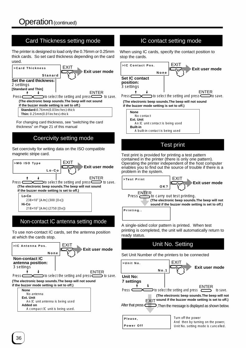
36
Operation (continued)
Coercivity setting mode
Set coercivity for writing data on the ISO compatiblemagnetic stripe card.
> M G I S O Ty p e
L o - C o
EXIT
ENTER
Exit user mode
Press to select the setting and press to save.(The electronic beep sounds.The beep will not sound if the buzzer mode setting is set to off.)
Lo-Co238×102 [A/m] (300 [Oe])
Hi-Co218×103 [A/m] (2750 [Oe])
Non-contact IC antenna setting mode
To use non-contact IC cards, set the antenna positionat which the cards stop.
> I C C o n t a c t P o s .
N o n e
EXIT
ENTER
Exit user mode
Set IC contact position:3 settings
Press to select the setting and press to save.(The electronic beep sounds.The beep will not sound if the buzzer mode setting is set to off.)
NoneNo contact
Ext. UnitAn IC unit contact is being used
Built-inA built-in contact is being used
IC contact setting mode
When using IC cards, specify the contact position tostop the cards.
Test print
Test print is provided for printing a test patterncontained in the printer (there is only one pattern).Operating the printer independent of the host computerenables you to find out the source of trouble if there is aproblem in the system.
> I C A n t e n n a P o s .
N o n e
EXIT
ENTER
Exit user mode
Non-contact IC antenna position:3 settings
Press to select the setting and press to save.(The electronic beep sounds.The beep will not sound if the buzzer mode setting is set to off.)
NoneNo antenna
Ext. UnitAn IC unit antenna is being used
Added onA compact IC unit is being used.
> Te s t P r i n t
O K ?
P r i n t i n g . .
ENTER
EXITExit user mode
Press to carry out test printing.(The electronic beep sounds.The beep will not sound if the buzzer mode setting is set to off.)
A single-sided color pattern is printed. When testprinting is completed, the unit will automatically return toready status.
Unit No. Setting
Set Unit Number of the printers to be connected
> U n i t N o .
N o . 1
EXIT
Unit No:7 settings
ENTER
P l e a s e ,
P o w e r O f f
After that press ,Then the message is displayed as shown below.
Exit user mode
Turn off the powerAnd then by turning on the power,Unit No. setting mode is cancelled.
(The electronic beep sounds.The beep will not sound if the buzzer mode setting is set to off.)
Press to select the setting and press to save.
EXIT
Card Thickness setting mode
The printer is designed to load only the 0.76mm or 0.25mmthick cards. So set card thickness depending on the cardused.
> C a r d T h i c k n e s s
S t a n a r d
EXIT
ENTER
Exit user mode
Set the card thickness:2 settings [Standard and Thin]
Press to select the setting and press to save.(The electronic beep sounds.The beep will not sound if the buzzer mode setting is set to off.)
Standard: 0.76mm(0.03inches)-thickThin: 0.25mm(0.01inches)-thick
For changing card thickness, see “switching the cardthickness” on Page 21 of this manual

37
(to the next page)
> N e t w o r k >
> > H o s t I n t e r f a c e
> > D H C P
L A N
O n
Printer name setting on the network
Interface type(LAN,USB)
Availability of DHCP(On, Off)
Press the ENTER key to enter Address Setting mode.See page 39 for the setting method.
Press to select the setting value and press to save.
�
ENTERMENU
MENU
MENU
EXIT
EXIT
EXIT
EXIT
ENTER
EXITExit user mode
•Even when LAN is selected for this setting initialization, the setting will become USB when USB interface is connected.
MENUEXIT
> > P r i n t e r N a m e
P R I N T E R 0 1
> > I P A d d r e s s
1 9 2 . 1 6 8 . 0 0 0 . 1 4 1
•Name that can be set from the printer are PRINTER01-10. Please set other name from the host computer.�
ENTER
�
IP Address Settings
Subnet Mask Settings
MENU
MENU
ENTER
Continue on next page
Press the ENTER key to enter Address Setting mode.See page 39 for the setting method.
•Setting when DHCP is Off.
•Setting when DHCP is Off.
(The electronic beep sounds .The beep will not sound if the buzzer mode setting is set to off.)
Press to select the setting value and press to save.ENTER
(The electronic beep sounds .The beep will not sound if the buzzer mode setting is set to off.)
Press to select the setting value and press to save.ENTER
(The electronic beep sounds .The beep will not sound if the buzzer mode setting is set to off.)
• When "DHCP On" is selected, the IP address, subnet mask, anddefault gateway values are automatically acquired from the DHCPserver. If the DHCPserver is not found, settings of the following "IP Address" will apply.• When "DHCP Off" is selected, specify the "IP Address", "SubnetMask", and "Default Gateway" gields accordingly.
Memo
> > S u b n e t M a s k
2 5 5 . 2 5 5 . 2 5 5 . 0
• Determine the “Network Setting” items according to the instruction of the network administrator for the location where the printer unit is installed.• Other network devices may be affected if the “Network Setting” is incorrect.
NETWORK setting
CAUTION

38
> > S e s s i o n T i m e O u t
> > M A C A d d r e s s
O f f
0 0 8 0 - 8 8 4 2 - 8 B 0 0
Session Time out time setting5 levels of time setting (off, 10sec, 20sec, 30sec, 60sec)
Display of MAC address
When IP Sec type is "not setting ", it is fixed at Off.
MENU
MENU
MENU
EXIT
EXIT
EXIT
EXITExit user mode
MENUEXIT
> > I P S e c m o d e
O f f
Availability of IP Sec (Off, On)
Displayed of the IP Sec authentication methodnot Setting(no definition), Preshared(presharing ofkey authentication), Certificate(Public key certificate))
MENU
From previous page
> N e t w o r k >
> > P r i n t e r N a m e
P R I N T E R 0 1
Return to top of the network settings on previous page.
MENUEXIT
ENTER
> > G a t e w a y
1 9 2 . 1 6 8 . 0 0 0 . 0 0 1
Default Gateway Setting
•Setting when DHCP is Off.
Press the ENTER key to enter Address Setting mode.See page 39 forhe setting method.
> > I P S e c Ty p e
n o t S e t t i n g
Turn off the power then turn it on againt o e n a b l e N e t w o r k s e t t i n g s .
CAUTION
Operation (continued)
MENURESET
ENTER
> > I P A d d r e s s O K ?
0 0 0 . 0 0 0 . 0 0 0 . 0 0 0
E n t e r s t o s e t t i n g m o d e .
0 0 0 . 0 0 0 . 0 0 0 . 0 0 0∗
U s e t h e ↑ ↓ k e y s t o c h a n g e t h e v a l u e o f t h e d i g i t a t t h e ∗ s y m b o l .
To i n c r e a s e , u s e ↑ k e y
To d e c r e a s e , u s e ↓ k e y
0 0 0 . 0 0 0 . 0 0 0 . 0 0 0∗
U s e t h e R E S E T a n d M E N U k e y t o c h a n g e t h e d i g i t a t t h e ∗ s y m b o l .RESET U s e R E S E T k e y t o
m o v e t h e * s y m b o l t o t h e l e f t ( ← ) a n d M E N U k e y t o m o v e i t t o t h e r i g h t ( → )
MENU�
� �
1 9 2 . 0 0 0 . 0 0 0 . 0 0 0∗
M o v e t o t h e d i g i t s t o b ec h a n g e e d a n d u s e t h e ↑ ↓ k e y s t o c h a n g e t h e Va l u e .�
1 9 2 . 1 6 8 . 0 0 0 . 0 0 1∗
EXIT ENTER
> > I P A d d r e s s O K ?
1 9 2 . 1 6 8 . 0 0 0 . 0 0 1
MENU
U s e t h e E X I T k e y t o r e t u r n t o t h e o r i g i n a ls e t t i n g
U s e t h e M E N U k e y t o p r o c e e d t o t h e n e x t s e t t i n g .
> > S u b n e t M a s k
2 5 5 . 2 5 5 . 2 5 5 . 0 0 0
I f t h e a d r e s s d i s p l a y e d m a t c h e s t h e a d d r e s s y o u
w a n t t o s e t , p r e s s t h e E N T E R k e y t o s a v e .
Input method Address Setting mode
To enter IP Address, Subnet Mask and DefaultGateway using Network Setting from the printer, pressEnter key at each setting screen to go into the AddressSetting mode.Use the following procedures to set the address.

39
CAUTIONWhen shipping or moving the printer,
you must set the transport mode. If the printer is not setthe transport mode, it may have a damage.
> T r a n s p o r t m o d e
O K ?
ENTER
EXIT
P l e a s e ,
P o w e r o f f
Exit user mode
Press to carry out transport mode.(The electronic beep sounds.The beep will not sound if the buzzer mode setting is set to off.)
Please turn off the power.Turning on the power, then the transport mode is canceled.
> D o w n l o a d
O K ?
Press ENTER key to set DOWNLOAD mode.ENTER
EXITExit user mode
(The electronic beep sounds, The beep will not sound if the buzzer mode setting to off)
When data is received from the Host computer,Downloading will be displayed.
> D o w n l o a d i n g
K e e p p o w e r O n
StartCompletion
> D o w n l o a d R e a d y > D o w n l o a d i n g >EXITP o w e r O f f
EXIT
> H R C o n t r o l
o f f
EXIT Exit user mode.
ENTER
Availability of heat roller control at the re-transfer side.(on,off)
(The electronic beep sounds .The beep will not sound if the buzzer mode setting is set to off.)
Press to select the setting press to save.
CAUTIONWhen data is transferring from thee
host computer, “Downloading” will be displayedIf the power is turned off at this time, the printer firmwarewill crash and the printer cannot operate.
Please set ON normally in this mode. When the printeris set ON in this mode, the printer will become standbyat low temperature of the retransfer heat roller after noprinting motion for 30 minutes and over. Thetemperature of the heat roller will automatically get anoriginal setting when next card printing commandreceived. For that reason, it takes long time for 1st cardcompared with normal printing.
Low temperature stand-by mode setting
Set the printer to DOWNLOAD mode.
DOWNLOAD mode setting
To set the transport mode.
Transport mode
1234
-567
8-90
AB
1234-5678-90AB
Starting Point of Print Area(0,0)
A
(764,18)
B(42,611)
(1035,663)
230Pixel
34Pixel
Fig. 1 Print Position of MAC address
Print position of MAC address in case that it is set atUpper Right position.
Direction of Retransfer
Print position of MAC address in case that it is set atLower Left position.
In case that UV is printed on YMC directly, printerror will be occurred when retransferring. So incase that YMC image is overlapped with UV image,please print UV image on the retransfer film afterYMC image is retransferred on the card. It isrequested to pay the same special attention forMAC address that is printed with UV ink. So in case that MAC address print area with UVink is overlapped with with YMC-K image, pleaseprint UV image on the retransfer film after YMC-Kˆimage is retransferred on the card.
Set position of MAC address print
In the case of UV print, MAC address must be printed at the
edge of a card at the same time. Position of MAC address isselectable between Right Upper Edge or Left Bottom Edge viaCommand or opration panel. Please refer to following picture 1about print position. Following mentioned coordinates are basedon “Starting point of Print Area” and indicated in pixels.
CAUTION

40
Care and cleaningAlways make sure that the printer is turned off before cleaning.(However, cleaning of the card feed rollers and magnetic head should be carried out with the power turned on.)To achieve the best performance from the printer, always check each part before use for dust and dirt and clean if necessary.The following explains the main rollers that require cleaning. For details about other rollers, see p.45 (Internal roller layout).Dust and dirt, particularly on the thermal head, rollers and cleaning rollers can cause print blurs and shifting of colors.
Cleaning the cleaning rollers
The cleaning rollers remove dust and dirt sticking to the card.Cleaning the cleaning rollers after every use is recommendedif the printer is used almost everyday. Depending on thecards, there may be much dust and dirt. In such a case,perform cleaning every 100 to 200 cards. Do not do this,however, during printing operations.
1. Open the card tray.
2. Remove the cleaning unit.Pull out the cleaning unit toward you as shown in theillustration below.
3. Wash the rollers of the cleaning unit with water.Wash out dirt on the roller surface with your fingers.Do not use alcohol or detergents. The cleaning unitshould be cleaned only with running water.
4. Push the cleaning unit back into the printer.Push the cleaning unit with the rollers facing upwarduntil it is securely back into the place.
5. Close the card tray.
After washing the cleaning unit withwater, wait until it completely dries up and set it in theprinter.
CAUTION
Deteriorated cleaning rollers maycause defects in the printed card. If the rollers begin todeteriorate, replace the cleaning unit.(We recommend replacement after a year)
CAUTION
When you remove the cleaning unit,be careful not to injure your fingers by inner mechanism.
CAUTION

41
(to the next page)
1
2
Cleaning the thermal head
When the thermal head gets dirty, defects such asunwanted lines appearing on the printed card mayoccur. It is recommended to clean the thermal headafter printing about 10,000 frames. The thermal head isa consumable component, that is, it has a limitedservice life.
1. Open the printer door and remove the ink ribboncassette and the retransfer film cassette.
See p.14, 16 in this manual.
2. Wipe the cleaning head with a cotton bud (soldseparately), dipped in alcohol (sold separately).
Wipe the head indicated with horizontally.
3. Insert the ink ribbon cassette and the retransferfilm cassette, then close the printer door.
Cleaning the fan filter
When the fan filter gets dirty, partial omissions mayoccur on the printed cards, or the printing result looksdirty. It is recommended to clean the fan filter afterprinting about 10,000 cards.
1. Remove the fan filters located in three positions onthe sides of the printer.
2. Remove the card tray.
See p.49 in this manual.
3. Remove the fan filter located on the base of theprinter (inside the unit).
Bring down the fan filter(side 2) while pressing its side(side 1). The fan filter can be taken out. Mount the fanfilter by pressing this side.
Thermalhead
Cotton bud (sold separately)
• The thermal head may break iftouched with an electrostatic charge. Discharge yourselfby touching the printer frame (metallic part) with yourhands before cleaning the thermal head.
• Use a cotton bud soaked with absolute alcohol(ethanol).Be careful not to scratch the thermal head with hardmaterials like metal during cleaning.
CAUTION

42
4. Remove dirt on the fan filter using a vacuumcleaner or other cleaning equipment.
Hold the sponge with your hand so that it is not suckedinto the cleaner.
Side filterPress down the sponge intothe dents at four corners, andset it under the tabs on theframe.
Bottom filterPlace the spongeunder the tabs on theframe.
Replace the fan filter when it begins to deteriorate.(the elasticityof the sponge is lost and the sponge tends to be broken intopieces.) It is recommended that fan filter should be replacedonce a year. Contact your dealer for details of replacing the filter.
If the sponge is removed, attach it again as shownbelow.
Cleaning the card feed rollers and heatrollers
Dirty rollers are the major cause of jamming of thecards. It is recommended to clean the rollers once afterprinting about 1,000 cards. It is also recommended tocarry out cleaning before the work, because theretransfer roller (heat roller) does not operate while it ishot.
1. Remove the retransfer film cassette.
See p.16 in this manual.
2. Turn on the power of the printer.The printer initializes, and the [No Cassette] error isindicated.
3. From user mode select cleaning mode.
4. Press the ENTER button. Select [Rollers] with ↑and ↓ buttons, and press the ENTER button.
See p.31 in this manual.
Insert the cleaning card in about 10 seconds. If you failsto set the card within this time, the printer returns to“Start OK?” Press the ENTER button again to proceed.
> C l e a n i n g >
> U s e r M o d e
MENU
> > R o l l e r s
O K ?
C l e a n i n g . .
S t a r t O K ?
ENTER
C l e a n i n g . .
ENTER
5. Install the fan filters back to the original positions.
Care and Cleaning (continued)

43
(to the next page)
Cleaning the magnetic head
Dirty magnetic head will cause a write/read error. It isrecommended to clean the magnetic head after printingabout 1,000 cards. Cleaning the magnetic head is notnecessary if the magnetic stripe card is not used.
1. Keep the ink ribbon and retransfer film cassettes intheir mounting positions.
2. Confirm that the READY LED (Green) is lighted
3. Specify the “cleaning” mode in the user mode.
See p.31 in this manual.
4. Apply alcohol on the magnetic head cleaning card.Drip three or four drops of alcohol on the magneticstripes.
5. Set a cleaning card.
Peel off the protective paper of the cleaning card andinsert it into the NG card discharge slot. The card will bedrawn into the unit by the rollers and cleaning will thenbe carried out from card discharge slot on the left sideof the printer. Insert the card with its adhesive faceupside down to repeat the cleaning procedure oncemore.
• If the retransfer roller (heat roller)gets too hot,
appears on the LCD panel, and the printer returns to theReady state.Turn off the power of the printer, and wait until the rollercompletely cools down before starting the work.Confirm that the retransfer film cassette has beenremoved.
• The cleaning card does not go into the card dischargeslot at the left side.
• If a card jam occurs, turn off the power, then turn on thepower again. The jammed card will be discarded.
CAUTION
H R i s t o o h o t !
Cleaning card (accessory)
The cleaning cardcan be inserted onlyfrom the right side.
NG card discharge slot
6. Turn off the power after the cleaning card isdischarged.
Wait for 10 seconds before turning on the power again.
The cleaning card can be used onlyonce and disposable after using. If you use the dirtycleaning card many times, the dirt on the card movesonto the rollers, causing damages to the rollers.Consult your dealer for the cleaning card.
CAUTION
> C l e a n i n g >
> U s e r M o d e
MENU
Magnetic head cleaningcard (sold separately)
Alcohol (soldseparately)

44
5. Set the card on the card tray.Place the card in right direction. See p.20.
6. Press the ENTER button, select “MG Head” withthe ↑ or ↓ button, and press the ENTER button.
7. When the cleaning card is discharged from NGcard discharge slot, turn off the power of theprinter. Wait for 10 seconds before turning on thepower again.
> > M G H e a d
O K ?
C l e a n i n g . .
ENTER
Replace the magnetic head cleaningcard when it gets dirty. A dirty card may pollute the headand cause damages to the head.Consult your dealer on the alcohol and cleaning card.
CAUTION
Once printer servicing and cleaninghave been completed
Once servicing and cleaning of the printer have beencompleted, check to make sure that all parts have beenreplaced properly.Improper replacement of parts may result in the powernot turning on or in operating errors.
Periodical Maintenance
Periodical maintenance by the service personnel isrecommended to avoid print error and failure.Consult your dealer for maintenance period and cost.
Cleaning of the bobbin holders
Dirt on the bobbin holders may appear on the card orthe film, cause defects on the card. Clean the bobbinswhen replacing ink ribbon or retransfer film.
1. Remove the cassettes of ink ribbon and retransferfilm.
See p.14 and 16 of this manual.
2. Wipe 4 bobbin holders with “Kim-Wipe” soakedwith absolute alcohol(ethanol)
Care and Cleaning (continued)

45
(to the next page)
J a m ( Tu r n O v e r )
J a m ( H o p p e r )
J a m ( T r a n s f e r )
Troubleshooting
Layout of rollers inside the printer
Below is a diagram of the layout of rollers inside the printer. Refer to this diagram in the event of card jams andwhen cleaning the rollers.
Retransfer film cassette Ink ribbon cassette
Thermal head
Card feed rollers
Card jams (see p.50)
Card jams (see p.49)
Card jams (see p. 50) Cleaning unit
Card feed rollers
Bend remedial roller (heat roller)
Retransfer roller (heat roller)
All rollers require routine cleaning.• The card feed rollers, retransfer roller and
bend remedial roller can be cleaned oncleaning mode.(See p.42, 43 in this manual.)
• The cleaning unit can be cleaned by waterwashing.(See p.40 in this manual.)
Magnetic head
Card turnover table
How to clean the feed roller1. Open the card tray, and take out the cards from the
tray.2. Move the card bracket until it locks.3. Clean the feed roller with felt (sold separately)
soaked with absolute alcohol(ethanol).
Feed roller
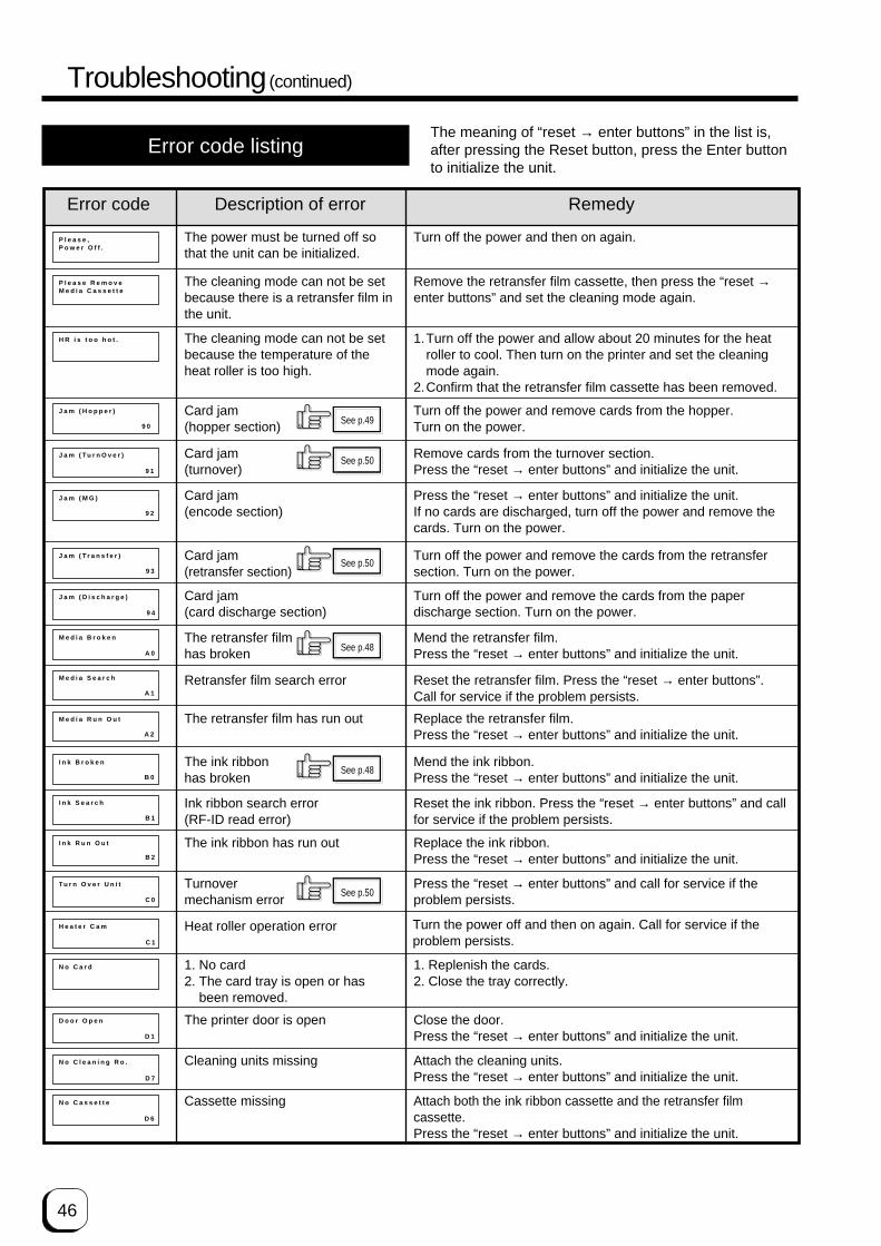
46
P l e a s e , �P o w e r O f f .
P l e a s e R e m o v e �M e d i a C a s s e t t e
H R i s t o o h o t .
J a m ( H o p p e r )
J a m ( Tu r n O v e r )
J a m ( M G )
J a m ( T r a n s f e r )
J a m ( D i s c h a r g e )
M e d i a B r o k e n
M e d i a S e a r c h
M e d i a R u n O u t
I n k B r o k e n
I n k S e a r c h
I n k R u n O u t
Tu r n O v e r U n i t
H e a t e r C a m
N o C a r d
D o o r O p e n
N o C l e a n i n g R o .
N o C a s s e t t e
9 0
9 1
9 2
9 3
9 4
A 0
A 1
A 2
B 0
B 1
B 2
C 0
C 1
D 1
D 7
D 6
Error code listingThe meaning of “reset → enter buttons” in the list is,after pressing the Reset button, press the Enter buttonto initialize the unit.
Error code Description of error Remedy
The power must be turned off sothat the unit can be initialized.
Turn off the power and then on again.
The cleaning mode can not be setbecause there is a retransfer film inthe unit.
Remove the retransfer film cassette, then press the “reset →enter buttons” and set the cleaning mode again.
The cleaning mode can not be setbecause the temperature of theheat roller is too high.
1.Turn off the power and allow about 20 minutes for the heatroller to cool. Then turn on the printer and set the cleaningmode again.
2.Confirm that the retransfer film cassette has been removed.
Card jam(hopper section)
Turn off the power and remove cards from the hopper.Turn on the power.
Card jam(turnover)
Remove cards from the turnover section.Press the “reset → enter buttons” and initialize the unit.
Card jam(encode section)
Press the “reset → enter buttons” and initialize the unit.If no cards are discharged, turn off the power and remove thecards. Turn on the power.
Card jam(retransfer section)
Turn off the power and remove the cards from the retransfersection. Turn on the power.
Card jam(card discharge section)
Turn off the power and remove the cards from the paperdischarge section. Turn on the power.
The retransfer filmhas broken
Mend the retransfer film.Press the “reset → enter buttons” and initialize the unit.
Retransfer film search error Reset the retransfer film. Press the “reset → enter buttons”.Call for service if the problem persists.
The retransfer film has run out Replace the retransfer film.Press the “reset → enter buttons” and initialize the unit.
The ink ribbonhas broken
Mend the ink ribbon.Press the “reset → enter buttons” and initialize the unit.
Ink ribbon search error(RF-ID read error)
Reset the ink ribbon. Press the “reset → enter buttons” and callfor service if the problem persists.
The ink ribbon has run out Replace the ink ribbon.Press the “reset → enter buttons” and initialize the unit.
Turnovermechanism error
Press the “reset → enter buttons” and call for service if theproblem persists.
Heat roller operation error
1. No card2. The card tray is open or has
been removed.
1. Replenish the cards.2. Close the tray correctly.
The printer door is open Close the door.Press the “reset → enter buttons” and initialize the unit.
Cleaning units missing Attach the cleaning units.Press the “reset → enter buttons” and initialize the unit.
Cassette missing Attach both the ink ribbon cassette and the retransfer filmcassette.Press the “reset → enter buttons” and initialize the unit.
See p.49
See p.50
See p.50
See p.48
See p.48
See p.50
Turn the power off and then on again. Call for service if theproblem persists.
Troubleshooting (continued)

47
(to the next page)
T R O v e r h e a t
T R B r o k e n
T R S e n s o r B r o k e n
R R O v e r h e a t
R R B r o k e n
R R S e n s o r B r o k e n
O v e r c o o l
H e a d O v e r h e a r t
E E P R O M B r o k e n
M G U n c o n n e c t e d
M G M e c h a n i c a l
M G H a r d w a r e �
E X T 2 C o m m u n i c a t e
H a r d w a r e �
E X T. U n c o n n e c t e d
H a r d w a r e
M G C o m m u n i c a t e
E X T. S W S e t t i n g
E X T. J a m
E X T. C o m m u n i c a t e
B 8
F 0
F 1
F 2
F 3
F 4
F 5
F 6
F 8
F A
A 9
A B
A C
B F
4 4
A F
B 9
B A
B B
B E
Error code Description of error Remedy
Retransfer roller overheating Turn off the power and then on again. Call for service if theproblem persists.
Should your printer require servicing, turn it off and unplug it and make inquiries at the outletwhere it was purchased.
Retransfer roller malfunction Turn off the power and then on again. Call for service if theproblem persists.
Retransfer roller thermistermalfunction
Turn off the power and then on again. Call for service if theproblem persists.
Bend remedy roller overheatingerror
Turn off the power and then on again. Call for service if theproblem persists.
Bend remedy roller malfunction Turn off the power and then on again. Call for service if theproblem persists.
Bend remedy roller thermistermalfunction
Turn off the power and then on again. Call for service if theproblem persists.
Overcool The usage environment temperature is too low.Use at the specified usage environment temperature.(Call for service if the problem persists.)
Thermal head overheated Turn off the power and leave the unit for about 10 minutes beforeswitching on again. (Call for service if the problem persists.)
EEPROM malfunction Turn off the power and then on again. Call for service if theproblem persists.
MG connection error Turn off the power and then on again. Call for service if theproblem persists.
MG mechanical error Turn off the power and then on again. Call for service if theproblem persists.
MG hardware error Turn off the power and then on again. Call for service if theproblem persists.
Hardware error Turn off the power and then on again. Call for service if theproblem persists.
Connected external devicemalfunctioning
MG communication error
External device switch setting error
Turn off the power and then on again. Call for service if theproblem persists.
External retransfer unit jam error Press the “reset → enter buttons” and remove cards if they arenot discharged. Press the “reset → enter buttons” and call forservice if the problem persists.
External unit communications error Check the I/F cable connected correctly.Turn off the power andthen on again. Call for service if the problem persists.
External unit2 communicationserror
Check the I/F cable connected correctly.Turn off the power andthen on again. Call for service if the problem persists.
Hardware error Turn off the power and then on again. Call for service if theproblem persists.
Check the I/F cable connected correctly.Turn off the power andthen on again. Call for service if the problem persists.
Turn off the power and then on again. Call for service if theproblem persists.

48
Mending broken ink ribbon andretransfer film
If the ink ribbon or retransfer film is broken, mend it inthe following procedures:
1. Trim neatly the end of broken portions with a pairof scissors.
2. Align both ends and apply the Scotch tape in thecenter of the aligned ends.
Please do not discard the used ink ribbon or retransfer film on the winding side.
3. Turn the ink ribbon or retransfer film to the windingside with your hand until the mended portion iscompletely wound up.
About printing errors
If blurring or color shifts occur in your print results, cleanall rollers starting with the cleaning rollers.Some image errors may depend on the design of thecard to print.In particular, wrinkles can easily occur if large surfacesare printed with high density ink.To avoid such problems, contact the dealer where theprinter was purchased concerning card designs.
Align bothends evenly
Scotch tape
Windingside
Set the ink ribbon and retransfer filmwith care. See p.14 and p.16.
CAUTION
Caution when printing characters
When printing small characters or thin lines in blackink, the thickness of minimum 2 dots necessary for“Standard” mode. Printing small characters or thin lines by 1 dot tends tocause blurring. To avoid this tendency, following settings arerecommended. See “Ink mode setting” on Page 32.1. Set the black value K: Try to increase setting value to more than 0 (Standard)Then darker printing is possible.2. Set the K printing mode: Change mode from “Standard” to “Fine”.Then thicker printing is possible.
If blurring still appears after having tried the abovesetting , selecting more adequate character font isrecommended.
When retransfer operation is not complete
Depending on the cards used, retransfer operation maynot be complete. In that case, try the following items.(See Page 33, “Retransfer mode setting”)1. Try to increase the retransfer temperature.2. Try to decrease the retransfer speed. For the reverseside of the card, try to decrease the reverse retransferspeed.3. Dust on the card surface. Use clean cards with nodust. Use the attached gloves to avoid finger mark oncards.4. Ambient temperatureRetransfer operation may not be complete if thetemperature of card surface is very low such as thecard first printed in the cold morning. In that case, waituntil the room becomes warm enough.
Stopping when printing
The printer may stop with no error messages If somefailure with the connection to the host computer occuror the not proper ink ribbon is set.In this case, open and close the printer door at once,and then press “reset” and press “enter” to initialize theprinter.
Troubleshooting (continued)

49
(to the next page)
Removing card jams
To determine the part of the machine affected by a cardjam refer to the error code on the operation panel LCDpanel on the printer and the relevant page in thismanual.When removing a jammed card, make sure that theprinter is turned off before carrying out the followingprocedure.
Hopper jam
1. Pull out the card tray.To remove the card tray, pull it out toward you until it nolonger moves and lift it.
2. Remove the jammed cards.
If you can hold the jammed card, pull it out.
3. Return the card tray to its original position.Push the card tray back into position on an angle.
Push the card tray backinto its position whileplacing the card tray tabson the folded over metalplates.
If you cannot hold the jammed card:Pull out a small portion of the cleaning unit.
Turn the right knob to drop the jammed card. Removethe fallen card.
Pushing the tray with excessive forcemay cause a failure of the printer.
CAUTION
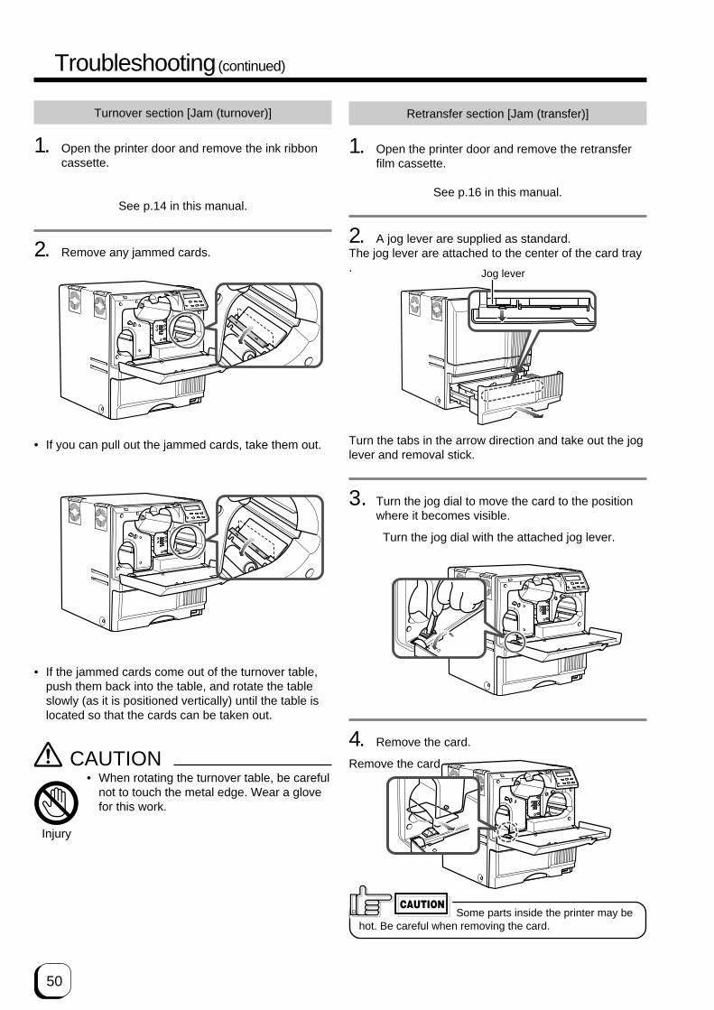
50
Turnover section [Jam (turnover)]
1. Open the printer door and remove the ink ribboncassette.
See p.14 in this manual.
2. Remove any jammed cards.
Retransfer section [Jam (transfer)]
1. Open the printer door and remove the retransferfilm cassette.
See p.16 in this manual.
2. A jog lever are supplied as standard.The jog lever are attached to the center of the card tray.
Turn the tabs in the arrow direction and take out the joglever and removal stick.
3. Turn the jog dial to move the card to the positionwhere it becomes visible.
Turn the jog dial with the attached jog lever.
4. Remove the card.
Remove the card.
Some parts inside the printer may behot. Be careful when removing the card.
CAUTION
• If the jammed cards come out of the turnover table,push them back into the table, and rotate the tableslowly (as it is positioned vertically) until the table islocated so that the cards can be taken out.
CAUTION• When rotating the turnover table, be careful
not to touch the metal edge. Wear a glovefor this work.
Injury
• If you can pull out the jammed cards, take them out.
Jog lever
Troubleshooting (continued)

51
(to the next page)Specifications
Main specifications
Recording method : Sublimation type retransferFeed format : Automatic feedRecording density : 300 dpiExpression gradation : 256 for Y, M, C and 2 for Bk
Interface : USB2.0(High-speed/ Full speed) Ethernet(100BASE-Tx/10BASE-
T)Operating environment conditions
Temperature: 15°C ~ 30°CHumidity: 35% ~ 70%(no condensation)
Storage environment conditionsTemperature: -15°C ~ 55°CHumidity: 20% ~ 80%
Power supply : 100~120ACV/220~240ACV50/60 Hz (allowance±10%)
Current dissipation : 7.0A (for 100V system) / 5.0A(for 200V system)
Wattage : 750W(Max.)Mass : Standard 22kg
Excluding the built-in magneticencoder
Dimension (cm) : 34.3(W) × 34.7(D) × 38.1(H)Accessories : Power cord for 120ACV
(North America) ..................... ×1for 220~240ACV(Europe) ................................ ×1Manual(English) .................... ×1Cleaning card ×1Card stacker ×1Ink ribbon cassette ×1Retransfer film cassette ×1USB cable(200cm) ×1Jog lever (contained in thecard tray) ×1Gloves ×1
CF-32ICM (Medium-type IC unit)Power supply : Fed from the printer.Mass : 0.6kgDimension (cm) : 7.6(W) × 17.1(D) × 11.5(H)
CX21ICS Series (Compact IC unit)Power supply : Fed from the printer.Mass : 0.5kgDimension (cm) : 5(W) × 15.2(D) × 11.5(H)Accessories : Screw (with washer) × 3
Screw (without washer) × 2
The specifications and external appearance of this product are subject to change for improvements withouta prior notice.
Products sold separately• Ink ribbon(YMCK)
• 1,000 frames/setModel: DIC10216
• Ink ribbon(YMCKK)• 750 frames/set
Model: DIC10217• Ink ribbon(YMCKU)
• 750 frames/setModel: DIC10313
• Retransfer film •1000 frames/set
Model: DIC10319
• Cleaning card 10 cards/set Model: CX210-CC1
• Compact IC unitNon-contact IC encoderModel: CX21ICS
• Medium-Type IC unitNon-contact IC encoderModel: CF-32ICM-D

52
External appearance and dimensions
Front view Side view
unit/cm
34.3 34.7
38.1
Specifications (continued)
In case of disposal
In case of disposal this unit, take care for compliance with the local law and regulations in your country.

Printed in JapanKAT-T313-004
0711(VP)© 2007 Digital Identification Solutions Group
Su
blim
atio
n typ
e re
tran
sfer p
rinte
r ED
Isecure
® XID
5xxie Retran
sfer Prin
ter Instru
ctio
n M
an
ua
l
Digital Identification Solutions GroupTeckstrasse 52, 73734 Esslingen, Germany
Phone : +49 711 341 689 - 0Facsimile : +49 711 341 689 - 550