DMX2PWM 9-channel - Traxon Technologies€¦ · 5 Setup Manual - DMX2PWM 9-channel Device...
20
DMX2PWM 9-channel Setup Manual
Transcript of DMX2PWM 9-channel - Traxon Technologies€¦ · 5 Setup Manual - DMX2PWM 9-channel Device...

DMX2PWM 9-channelSetup Manual

DMX2PWM 9-channel Setup ManualEdition: 06.12.12 Published by:
Traxon Technologies Europe GmbH Karl Schurz-Strasse 38 Paderborn, Germany ©2012, Traxon Technologies Europe GmbH All rights reserved Comments to: [email protected]

Table of Contents
Safety instructions .................................................................................... 4
Device description .................................................................................... 5Key features......................................................................................... 5
Delivery Content ....................................................................................... 6
Hardware Installation ................................................................................ 6Interfaces & cabling ............................................................................. 6DMX .................................................................................................... 8
External power source jumper ................................................................. 9
Device Setup .......................................................................................... 10Manual address settings .................................................................... 10Auto addressing mode....................................................................... 10
Status LEDs ............................................................................................ 11
Technical data ........................................................................................ 12
Certifications .......................................................................................... 13
Dimensions ............................................................................................. 14
Appendix ................................................................................................ 16Dimming ............................................................................................ 16
Notes ...................................................................................................... 18

4
Setup Manual - DMX2PWM 9-channel
Safety instructions
!Only use the device in compliance with the environmental conditions specified and watch the technical characteristics. Otherwise the unit may be damaged or malfunction will happen.
!Only use original e:cue accessories to power the device Other power supplies can damage the unit.
!To prevent the device from overheating, only operate it in well-ventilated environment. Ventilation may not be obstructed. Do not install next to heat emitting sources or in a place subject to direct sunlight. Overheating damages the device.
Device components inside the system can reach high temperatures! To avoid burns, allow the unit to cool for at least 20 minutes before unmount or repair.
!Installation and maintenance of this product must be performed by indi-viduals who are knowledgeable about the procedures, precautions and hazards associated with the product.
!Do not route network, DMX or any other communication line together with power lines. Data traffic or functions can be disturbed.

5
Setup Manual - DMX2PWM 9-channel
Device descriptionThe e:cue DMX2PWM PWM LED Dimmer is a 9 channel DIN rail mounted dimmer for use with constant voltage fixtures. The input voltage is variable from 12-48 V DC and each output channel has a maximum output current of 2 A. Every output channel can be individually controlled via DMX and the DMX output allows chaining of multiple devices.
The option to either manually or automatically address the dimmer to a DMX Channel provides a simple solution for small to complex control scenarios. The reverse supply protection and self-resetting overcurrent protection do help to avoid malfunction and damage caused by faulty connections. Two status LEDs show the status of the dimmer and the status of the incoming DMX signal. Screw terminals provide connectivity for power input, PWM output and the DMX signal input and output.
Key features
• For use with constant voltage fixtures
• Isolated DMX-out for chaining multiple dimmers
• Two user selectable DMX addressing modes: auto addressing or manual addressing
• Input voltage range: 12 ... 48 V DC
• Max. output current of 2 A per channel (overcurrent protected)
• Max. continuos input current: 14 A in 14 bit PWM resolution calculated from 8 bit DMX value
• Low side switching
• Reverse supply protection
• Overcurrent protection (self resetting)
• DIN rail housing

6
Setup Manual - DMX2PWM 9-channel
Delivery ContentDMX2PWM 9ch. dimmer 160126
Hardware Installation
Interfaces & cabling
For the use of the DMX2PWM dimmer device a DC power supply is necessary. The choice of the power supply voltage only depends on the supply voltage of your LED fixtures, but must remain in the range from 12 V to 48 V DC. Please consider that the power supply must be able to provide the current for the connected LED fixtures and the DMX2PWM dimmer. Multiple LED fixtures where each one needs a different voltage level cannot be used with one dimmer device at the same time.
The (+) line of the Power supply connection (“power in”) is directly routed to the (+) connector of each PWM output. The following picture shows the basic connection scheme:

7
Setup Manual - DMX2PWM 9-channel
The advantage of the above shown type of connection is the reverse supply protection of all LED fixtures and the dimmer itself. Alternatively it is also possible to connect LED fixtures as shown in the figure at the right side.
Alternative connection scheme:
!Always select the power supply output voltage accordingly to your LED fixture input voltage. Make sure that the power supply cables are speci-fied to carry the complete amount of current needed by the connected LED fixtures.
The PWM switching node is designed as a low-side switch and is able to handle a maximum current of 2 A. Each output channel is short circuit protected. As soon as an overcurrent or short circuit situation is detected, the switch of the corresponding channel will immediately shut down. The STATUS LED is blinking to signal the over-current error. The dimmer tests the output repeatedly if the overcurrent still exists. It will re-enable the output as soon as the overcurrent is removed.

8
Setup Manual - DMX2PWM 9-channel
DMX
A DMX master must be attached to the DMX-In connector. If a valid DMX signal is detected by the DMX2PWM device, the green DMX LED is lit. To connect multiple devices in a chain, connect the DMX-Out port of the first device to the DMX-In port of the next device. For details about setting up a DMX address, please refer to chapter 4.
The DMX-Out port is galvanically isolated from DMX-In and other parts of the dim-mer. Please do not short circuit the GND connectors of DMX-Out and DMX-In. The isolated DMX-Out eliminates the risk of ground loops when using multiple dimmers is a chain.
The DMX2PWM 9-channel dimmer is equipped with two kinds of connectors for DMX. Depending on your installation you can either use the RJ45 connector or the screw terminals. The corresponding contacts of the RJ45 connector and screw terminals are shortened.
! Do not connect DMX-In screw terminals and RJ-45 at the same time!
DMX RJ45 connections
DMX1–DMX1+
GND
J1
RJ45-2X4
1
2
3
4
5
6
7
8

9
Setup Manual - DMX2PWM 9-channel
External power source jumperThe DMX2PWM dimmer is equipped with a jumper to enable power sourcing on the RJ45 DMX-In connector pin 5. The default setting at delivery is “off” (position 2-3). When enabled (position 1-2), the power supply is directly routed to pin 5 of the RJ45 connector. This is especially useful when using the DMX2PWM in combina-tion with the Glass Touch user terminals from e:cue. No additional power supply is needed.
!When using the dimmer’s power sourcing in combination with Glass Touch devices, the user has to ensure that the maximum power supply voltage is limited to 24 V DC!
To access the jumper, open the housing’s top cover by removing the two screws at the top side. The jumper is located near the RJ45 connector.
10
Setup Manual - DMX2PWM 9-channel
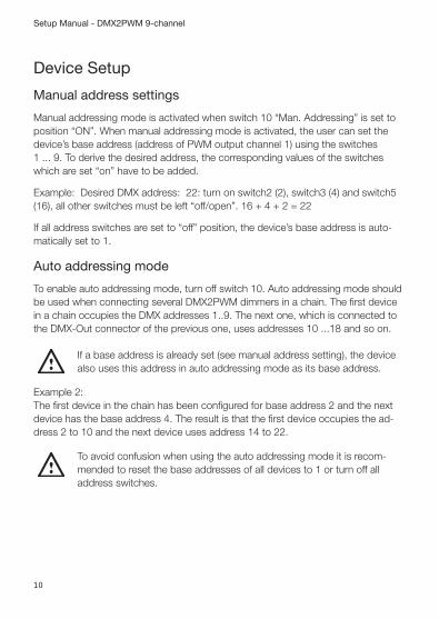
Device Setup
Manual address settings
Manual addressing mode is activated when switch 10 “Man. Addressing” is set to position “ON”. When manual addressing mode is activated, the user can set the device’s base address (address of PWM output channel 1) using the switches 1 ... 9. To derive the desired address, the corresponding values of the switches which are set “on” have to be added.
Example: Desired DMX address: 22: turn on switch2 (2), switch3 (4) and switch5 (16), all other switches must be left “off/open”. 16 + 4 + 2 = 22
If all address switches are set to “off” position, the device’s base address is auto-matically set to 1.
Auto addressing mode
To enable auto addressing mode, turn off switch 10. Auto addressing mode should be used when connecting several DMX2PWM dimmers in a chain. The first device in a chain occupies the DMX addresses 1..9. The next one, which is connected to the DMX-Out connector of the previous one, uses addresses 10 ...18 and so on.
!If a base address is already set (see manual address setting), the device also uses this address in auto addressing mode as its base address.
Example 2: The first device in the chain has been configured for base address 2 and the next device has the base address 4. The result is that the first device occupies the ad-dress 2 to 10 and the next device uses address 14 to 22.
!To avoid confusion when using the auto addressing mode it is recom-mended to reset the base addresses of all devices to 1 or turn off all address switches.

11
Setup Manual - DMX2PWM 9-channel
Status LEDs
LED Description
DMX off or flickering No DMX signal recognized or not connected
DMX on DMX present
STATUS off Power supply not connected
STATUS on Normal operation
STATUS blinking Overcurrent detected on one or more channels

12
Setup Manual - DMX2PWM 9-channel
Technical dataArt.-No.
Item number #160126
Dimensions mm/inch (WxHxD) 107 x 76 x 59 mm / 4.21 x 2.99 x 2.32 inch
Weight 0,228 kg/0.5 lb.
Power 12 ... 48 V DC (screw term.)
Operating Temperature 0°... 50° C/32°... 122° F
Storage Temperature -20° ... 80° C/-4° ... 176° F
Operating/Storage Hum. 0 ... 80%, not condensing
Protection class IP20
Housing Aluminium, Plastic
Certifications CE (EN55015 / EN61547)
Inputs DMX512 (RJ-45 or screw terminals)
Outputs Isolated DMX512 (RJ-45 or screw terminals) for chaining multiple devices 9 output channels (screw terminals): + connector: identical to input voltage - connector: low side PWM switch
Device Type Lamp control gear
Supply Voltage 12 ... -48 V DC (SELV equivalent) nominal, 5 .. 55 V DC absolute maximum supply input is reverse voltage protected
Power Consumption 0.8 W (idle, all channels off, DMX connected)
Output current per channel 2 A (Overcurrent protection, ±10%)
max. Input current at “power in” 14 A
max. Output load capacitance 1 µF
Overcurrent retry delay 1 sec.
Minimum on time 2.5 µs
PWM frequency 488 Hz
PWM resolution 14 bit (optimized dimming curve calculated from 8bit DMX value)

13
Setup Manual - DMX2PWM 9-channel
Data transmission DMX512 and e:pix
max. Devices in a chain 32 (depends on cable length and quality)
max. Wire cross section 1.5 mm² (for PWM outputs) (max. 2.5 mm² for power supply)
Certifications
(EN55015/EN61547)
4000805
ETL LISTED Conforms to ANSI/UL Std 60950-1 Certified to CAN/CSA STD C22.2 No. 60950-1

14
Setup Manual - DMX2PWM 9-channel
DimensionsAll dimensions in mm and inch.
45,5 / 1.79
76 / 2.99

15
Setup Manual - DMX2PWM 9-channel
58,4 / 2.3
107 / 4.21
16
Setup Manual - DMX2PWM 9-channel
Appendix
Dimming
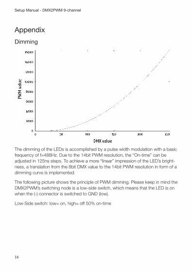
The dimming of the LEDs is accomplished by a pulse width modulation with a basic frequency of f=488Hz. Due to the 14bit PWM resolution, the “On-time” can be adjusted in 125ns steps. To achieve a more “linear” impression of the LED’s bright-ness, a translation from the 8bit DMX value to the 14bit PWM resolution in form of a dimming curve is implemented.
The following picture shows the principle of PWM dimming. Please keep in mind the DMX2PWM’s switching node is a low-side switch, which means that the LED is on when the (-) connector is switched to GND (low).
Low-Side switch: low= on, high= off 50% on-time

17
Setup Manual - DMX2PWM 9-channel
pulsewidth
f
25%On-time
75%On-time

18
Setup Manual - DMX2PWM 9-channel
Notes

19
Setup Manual - DMX2PWM 9-channel

Downloads and more information at www.traxontechnologies.com and www.ecue.com
HONG KONG SHANGHAI TOKYO SINGAPORE ROTTERDAM COLOGNE LONDON
MADRID MILAN PARIS ISTANBUL DENMARK MOSCOW WARSZAWA VIENNA
NEW YORK TORONTO DUBAI BUENOS AIRES MEXICO D.F. SAO PAULO COLOMBIA
MUMBAI
FLEXIBILITY, SIMPLICITY & INNOVATION IN LIGHTING SOLUTIONS & SERVICES