DMX-512 RGB LED Wash Light Control Board - … · ... 2010 Table of Contents DMX ... LEDs and...
13
http://www.instructables.com/id/DMX-512-RGB-LED-Wash-Light-Control-Board/ Food Living Outside Play Technology Workshop DMX-512 RGB LED Wash Light Control Board by ChromationSystems on April 14, 2010 Table of Contents DMX-512 RGB LED Wash Light Control Board . . . . . . . . . . . . . . . . . . . . . . . . . . . . . . . . . . . . . . . . . . . . . . . . . . . . . . . . . . . . . . . . . . . . . . . . . . . . . . . . . . . . . . . . 1 Intro: DMX-512 RGB LED Wash Light Control Board . . . . . . . . . . . . . . . . . . . . . . . . . . . . . . . . . . . . . . . . . . . . . . . . . . . . . . . . . . . . . . . . . . . . . . . . . . . . . . . . 2 Step 1: Layout the Parts . . . . . . . . . . . . . . . . . . . . . . . . . . . . . . . . . . . . . . . . . . . . . . . . . . . . . . . . . . . . . . . . . . . . . . . . . . . . . . . . . . . . . . . . . . . . . . . . . . . . . 3 Step 2: Resistors and Sockets . . . . . . . . . . . . . . . . . . . . . . . . . . . . . . . . . . . . . . . . . . . . . . . . . . . . . . . . . . . . . . . . . . . . . . . . . . . . . . . . . . . . . . . . . . . . . . . . . 4 Step 3: Oscillator and Capacitors . . . . . . . . . . . . . . . . . . . . . . . . . . . . . . . . . . . . . . . . . . . . . . . . . . . . . . . . . . . . . . . . . . . . . . . . . . . . . . . . . . . . . . . . . . . . . . . 5 Step 4: Interconnect Headers . . . . . . . . . . . . . . . . . . . . . . . . . . . . . . . . . . . . . . . . . . . . . . . . . . . . . . . . . . . . . . . . . . . . . . . . . . . . . . . . . . . . . . . . . . . . . . . . . 6 Step 5: Jumpers & 7805 Regulator . . . . . . . . . . . . . . . . . . . . . . . . . . . . . . . . . . . . . . . . . . . . . . . . . . . . . . . . . . . . . . . . . . . . . . . . . . . . . . . . . . . . . . . . . . . . . 6 Step 6: Prepare Interconnects . . . . . . . . . . . . . . . . . . . . . . . . . . . . . . . . . . . . . . . . . . . . . . . . . . . . . . . . . . . . . . . . . . . . . . . . . . . . . . . . . . . . . . . . . . . . . . . . . 7 Step 7: Wire Mode Switch And Speed Pot . . . . . . . . . . . . . . . . . . . . . . . . . . . . . . . . . . . . . . . . . . . . . . . . . . . . . . . . . . . . . . . . . . . . . . . . . . . . . . . . . . . . . . . . 8 Step 8: DIP Switch, Mic, Sound Pot . . . . . . . . . . . . . . . . . . . . . . . . . . . . . . . . . . . . . . . . . . . . . . . . . . . . . . . . . . . . . . . . . . . . . . . . . . . . . . . . . . . . . . . . . . . . . 9 Step 9: XLR Connectors . . . . . . . . . . . . . . . . . . . . . . . . . . . . . . . . . . . . . . . . . . . . . . . . . . . . . . . . . . . . . . . . . . . . . . . . . . . . . . . . . . . . . . . . . . . . . . . . . . . . . 10 Step 10: Plug in the ICs . . . . . . . . . . . . . . . . . . . . . . . . . . . . . . . . . . . . . . . . . . . . . . . . . . . . . . . . . . . . . . . . . . . . . . . . . . . . . . . . . . . . . . . . . . . . . . . . . . . . . . 11 Step 11: Breakout board and Testing . . . . . . . . . . . . . . . . . . . . . . . . . . . . . . . . . . . . . . . . . . . . . . . . . . . . . . . . . . . . . . . . . . . . . . . . . . . . . . . . . . . . . . . . . . . . 11 Step 12: Use it in a Wash Light . . . . . . . . . . . . . . . . . . . . . . . . . . . . . . . . . . . . . . . . . . . . . . . . . . . . . . . . . . . . . . . . . . . . . . . . . . . . . . . . . . . . . . . . . . . . . . . . 13
Transcript of DMX-512 RGB LED Wash Light Control Board - … · ... 2010 Table of Contents DMX ... LEDs and...

http://www.instructables.com/id/DMX-512-RGB-LED-Wash-Light-Control-Board/
Food Living Outside Play Technology Workshop
DMX-512 RGB LED Wash Light Control Boardby ChromationSystems on April 14, 2010
Table of Contents
DMX-512 RGB LED Wash Light Control Board . . . . . . . . . . . . . . . . . . . . . . . . . . . . . . . . . . . . . . . . . . . . . . . . . . . . . . . . . . . . . . . . . . . . . . . . . . . . . . . . . . . . . . . . 1
Intro: DMX-512 RGB LED Wash Light Control Board . . . . . . . . . . . . . . . . . . . . . . . . . . . . . . . . . . . . . . . . . . . . . . . . . . . . . . . . . . . . . . . . . . . . . . . . . . . . . . . . 2
Step 1: Layout the Parts . . . . . . . . . . . . . . . . . . . . . . . . . . . . . . . . . . . . . . . . . . . . . . . . . . . . . . . . . . . . . . . . . . . . . . . . . . . . . . . . . . . . . . . . . . . . . . . . . . . . . 3
Step 2: Resistors and Sockets . . . . . . . . . . . . . . . . . . . . . . . . . . . . . . . . . . . . . . . . . . . . . . . . . . . . . . . . . . . . . . . . . . . . . . . . . . . . . . . . . . . . . . . . . . . . . . . . . 4
Step 3: Oscillator and Capacitors . . . . . . . . . . . . . . . . . . . . . . . . . . . . . . . . . . . . . . . . . . . . . . . . . . . . . . . . . . . . . . . . . . . . . . . . . . . . . . . . . . . . . . . . . . . . . . . 5
Step 4: Interconnect Headers . . . . . . . . . . . . . . . . . . . . . . . . . . . . . . . . . . . . . . . . . . . . . . . . . . . . . . . . . . . . . . . . . . . . . . . . . . . . . . . . . . . . . . . . . . . . . . . . . 6
Step 5: Jumpers & 7805 Regulator . . . . . . . . . . . . . . . . . . . . . . . . . . . . . . . . . . . . . . . . . . . . . . . . . . . . . . . . . . . . . . . . . . . . . . . . . . . . . . . . . . . . . . . . . . . . . 6
Step 6: Prepare Interconnects . . . . . . . . . . . . . . . . . . . . . . . . . . . . . . . . . . . . . . . . . . . . . . . . . . . . . . . . . . . . . . . . . . . . . . . . . . . . . . . . . . . . . . . . . . . . . . . . . 7
Step 7: Wire Mode Switch And Speed Pot . . . . . . . . . . . . . . . . . . . . . . . . . . . . . . . . . . . . . . . . . . . . . . . . . . . . . . . . . . . . . . . . . . . . . . . . . . . . . . . . . . . . . . . . 8
Step 8: DIP Switch, Mic, Sound Pot . . . . . . . . . . . . . . . . . . . . . . . . . . . . . . . . . . . . . . . . . . . . . . . . . . . . . . . . . . . . . . . . . . . . . . . . . . . . . . . . . . . . . . . . . . . . . 9
Step 9: XLR Connectors . . . . . . . . . . . . . . . . . . . . . . . . . . . . . . . . . . . . . . . . . . . . . . . . . . . . . . . . . . . . . . . . . . . . . . . . . . . . . . . . . . . . . . . . . . . . . . . . . . . . . 10
Step 10: Plug in the ICs . . . . . . . . . . . . . . . . . . . . . . . . . . . . . . . . . . . . . . . . . . . . . . . . . . . . . . . . . . . . . . . . . . . . . . . . . . . . . . . . . . . . . . . . . . . . . . . . . . . . . . 11
Step 11: Breakout board and Testing . . . . . . . . . . . . . . . . . . . . . . . . . . . . . . . . . . . . . . . . . . . . . . . . . . . . . . . . . . . . . . . . . . . . . . . . . . . . . . . . . . . . . . . . . . . . 11
Step 12: Use it in a Wash Light . . . . . . . . . . . . . . . . . . . . . . . . . . . . . . . . . . . . . . . . . . . . . . . . . . . . . . . . . . . . . . . . . . . . . . . . . . . . . . . . . . . . . . . . . . . . . . . . 13
http://www.instructables.com/id/DMX-512-RGB-LED-Wash-Light-Control-Board/
Author:ChromationSystems www.chromationsystems.comDesigning electronic creations from microcontrollers, LEDs and anything else I can pull out of a dumpster and make use of.
Intro: DMX-512 RGB LED Wash Light Control Board A full featured driver board to control Red, Green, & Blue LEDs. When paired with the correct output board, it can control any arrangement of LEDs. Common Cathode,Common Anode, single color LEDs. From 1/8 watt LEDs to 3 watt LED arrangements.
4 stand-alone modes. Fade & Flash with speed adjustment via potentiometer. Manual color select via the same potentiometer. Sound reactivity withsensitivity adjustment and secondary adjustment.
Full DMX-512 addressing. Connect to a DMX Controller or a DMX computer program. 5 channels for Red, Green, Blue, Function, Speed.
Easy to control, a 3 position switch, a potentiometer for adjustment, and another potentiometer for sound sensitivity. 10 position DIP switch, 1-9 for DMX address, DIP 10is for standalone controls.
Datasheet Can Be Found Here, For More Files and Updates Visit My Main Website
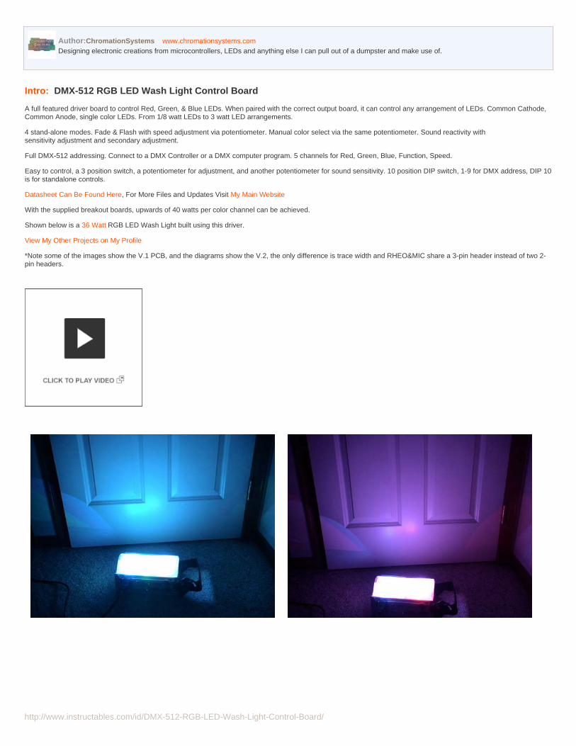
With the supplied breakout boards, upwards of 40 watts per color channel can be achieved.
Shown below is a 36 Watt RGB LED Wash Light built using this driver.
View My Other Projects on My Profile
*Note some of the images show the V.1 PCB, and the diagrams show the V.2, the only difference is trace width and RHEO&MIC share a 3-pin header instead of two 2-pin headers.

http://www.instructables.com/id/DMX-512-RGB-LED-Wash-Light-Control-Board/
Step 1: Layout the PartsKits for this Entire Project can Purchased in My Store Kits including a 3 watt RGB LED Can Be Found Here
If not all the parts are required, ex. No DIP Switch, XLRs, sound controlPlease Contact Me and I can put together a customized Kit.
Parts:- PCB- PIC 16F688, programmed- PIC 16F88, programmed- LM386- 20 mhz Series Oscillator- 8-pin socket- 14-pin socket- 18 pin socket- 10 position DIP Switch, DMX address selection- Triple Pole Triple Pole Switch, Stand-Alone Mode Selection- 15x 10k 1/4w Resistors- 1x 1k ohm 1/4w resistor, R2- 7805, TO-220 Voltage Regulator- 1x 1uF 100v Capacitor, C1- 1x 1uF 25v Capacitor, C2- 2x 10uF capacitor, C6 & C7- 2x 0.1uF disc Capacitor, C4 & C3- 1x Panel Mount Male XLR- 1x Panel Mount female XLR- 1x Electret Microphone- 1x 10k ohm Logarithmic Potentiometer- 1x Common Cathode RGB LED for Testing.- 1x 2-pin Header & Housing- 2x 3-pin Header & Housing- 1x 4-pin Header & Housing- 1x 6-pin header & Housing- 1x 12-pin Header & housing- Crimps- A Breakout board, chosen for the correct use. Just Ask Or a different form of current regulation that accepts TTL PWM, such as BuckPlus Line
Part Images and Description
.
http://www.instructables.com/id/DMX-512-RGB-LED-Wash-Light-Control-Board/
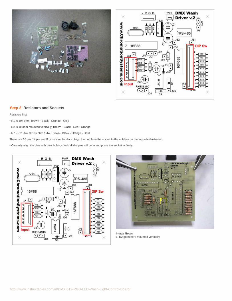
Step 2: Resistors and Sockets
Resistors first.
• R1 is 10k ohm, Brown - Black - Orange - Gold
• R2 is 1k ohm mounted vertically, Brown - Black - Red - Orange
• R7 - R21 Are all 10k ohm 1/4w, Brown - Black - Orange - Gold
There is a 16 pin, 14 pin and 8 pin socket to place. Align the notch on the socket to the notches on the top-side illustration.
• Carefully align the pins with their holes, check all the pins will go in and press the socket in firmly.
Image Notes1. R2 goes here mounted vertically

http://www.instructables.com/id/DMX-512-RGB-LED-Wash-Light-Control-Board/
Step 3: Oscillator and Capacitors
Oscillator:
- Find the 20mhz oscillator and solder it into OSC. It has no polarity but Make sure its a good solder joint.
Capacitors Next.The top-side illustration shows their polarity, the black solid stripe is the negative lead. - Find the two 1uF caps that will be soldered into C1 & C2. They do have polarity, the side with the stripe is the negative lead.
- Place the two 10uF capacitors next. C6 & C7. Again mind the polarity.
- Finally place a 0.1uF disc capacitor in C3 & C4. They have no polarity and can go in either way.
A mistake was made on the part naming and there is no C5.
Image Notes1. 1uf Caps, 25v or more.2. 10uf3. 10uf4. 0.1uf5. 0.1uF6. Oscillator

http://www.instructables.com/id/DMX-512-RGB-LED-Wash-Light-Control-Board/
Step 4: Interconnect Headers
Polarized headers allows wires to be plugged and unplugged from the PCB easily. This project has a lot of switches, potentiometers, mic, that aren't on the board andhave wires running to them. The wires are connected to crimps and the crimps are slid into the housings, more details on Step 6
Depending on kit variation some or all of these headers may be included. They are not necessary but make things easier. With out them the wires of the switches ect willneed to soldered directly onto the board, making installation harder.
I would recommend to try not to use a header and just solder the wires in directly to the PCB where possible.
There is an illustration of how the headers should be placed on the board. They have a polarized friction lock so a switch or voltage input cannot be plugged in backwardslater.
There is a 12-pin, 6-pin, 3-pin, and 3x 2-pin headers to solder.
Press them firmly in, flush with the PCB and start soldering. Careful not to bridge solder joints.
- The 12-pin is for the 10-position DIP switch for DMX Address Selection and Mode Select.
- The 6-pin header is for the Mode Switch and Speed Potentiometer.
- The 3-pin is for XLR hook-ups
- A 2-pin header labled PWR is for voltage input, polarity marked on the PCB*UPDATE: The polarity markings are reversed on the PCB
- The last two 2-pin headers are for sound input(rheostat and microphone), it is optimal to not install these headers and to wire the rheostat and mic directly PCB.
Image Notes1. Jumper should be in next step.
Step 5: Jumpers & 7805 Regulator
Now that almost all the rest of the components are placed, its a good time to do all the jumpers. Which are used instead of dual-layer PCBs.
Use some solid-strand wire and carefully find a route for the jumpers to follow, the path shouldn't ever cross over another jumper wire.
The jumpers are as follows:
JA1 goes to JA2JB1 goes to JB2JC1 goes to JC2
continues to JF1&2
*Note: JC4 is a misprint, ignore it.
Final Jumpers: if the output doesn't need the resistors to be used, jump the resistors R3, R4, and R5
Finally Place the 7805 as pictured. Solder it in well.
http://www.instructables.com/id/DMX-512-RGB-LED-Wash-Light-Control-Board/
Image Notes1. 7805
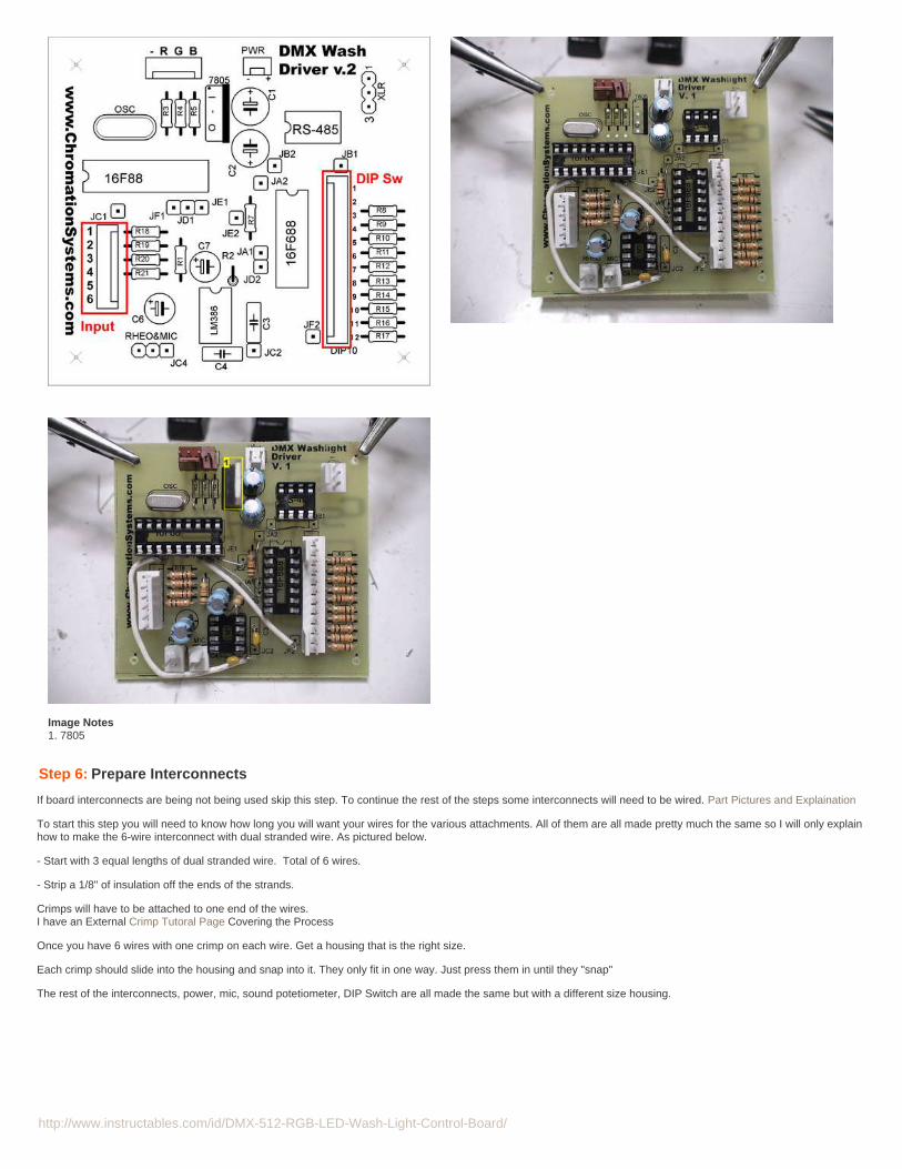
Step 6: Prepare Interconnects
If board interconnects are being not being used skip this step. To continue the rest of the steps some interconnects will need to be wired. Part Pictures and Explaination
To start this step you will need to know how long you will want your wires for the various attachments. All of them are all made pretty much the same so I will only explainhow to make the 6-wire interconnect with dual stranded wire. As pictured below.
- Start with 3 equal lengths of dual stranded wire. Total of 6 wires.
- Strip a 1/8" of insulation off the ends of the strands.
Crimps will have to be attached to one end of the wires.I have an External Crimp Tutoral Page Covering the Process
Once you have 6 wires with one crimp on each wire. Get a housing that is the right size.
Each crimp should slide into the housing and snap into it. They only fit in one way. Just press them in until they "snap"
The rest of the interconnects, power, mic, sound potetiometer, DIP Switch are all made the same but with a different size housing.

http://www.instructables.com/id/DMX-512-RGB-LED-Wash-Light-Control-Board/
Image Notes1. This is what is getting made.
Image Notes1. Would get cut here2. Crimped
Step 7: Wire Mode Switch And Speed Pot
Start with the switch, the mode switch included in the kit is a double pole, triple throw and it needs to get jumped so it can act as a 3 position switch. It is used for stand-alone function selecting.
- Just use a resistor clipping and solder in as pictured.
Next the 6-pin interconnect for the previous step needs to be soldered to the switch. Reference the top-side illustration and the chart below to figure out what wires willneed to go where on the mode switch or the speed pot.
6 Pin Header Pinout for Mode Switch1. Control Pot. Center Tap2. DMX Select3. Auto Select4. Manual/Audio Select5. Negative, 0 volts6. Positive, +5 volts
- DMX Select, Auto Select and Manual select are soldered to a position on the switch.
- Negative gets soldered to the pins on the switch that were jumped, and another strand of wire is used to go from negative to a side lug on the control pot.
- Control Pot is soldered to the center lug on the 2.5k ohm panel mount potentiometer.
- Positive is soldered to the remaining lug on the control pot.
Image Notes1. Position One2. Postion 23. Position 34. Common (Grounded)5. Common, Grounded
http://www.instructables.com/id/DMX-512-RGB-LED-Wash-Light-Control-Board/
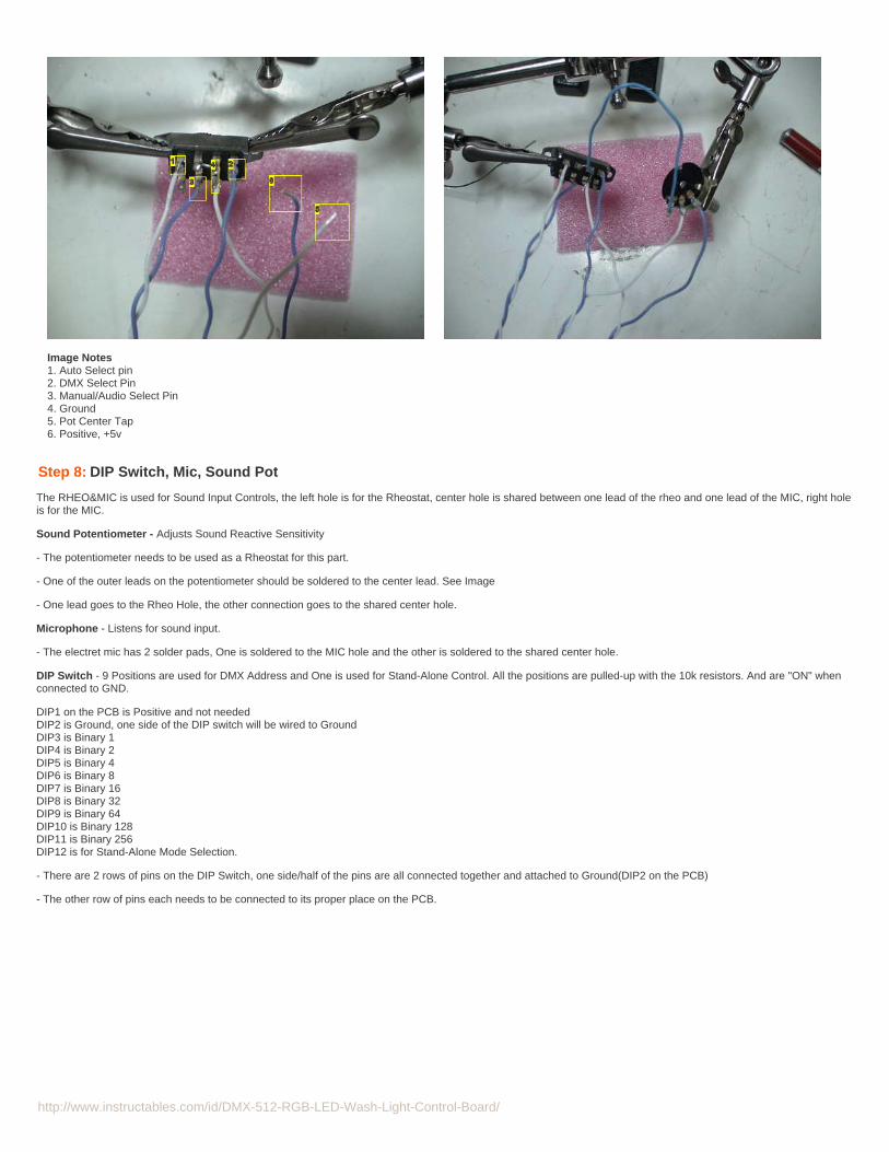
Image Notes1. Auto Select pin2. DMX Select Pin3. Manual/Audio Select Pin4. Ground5. Pot Center Tap6. Positive, +5v
Step 8: DIP Switch, Mic, Sound Pot
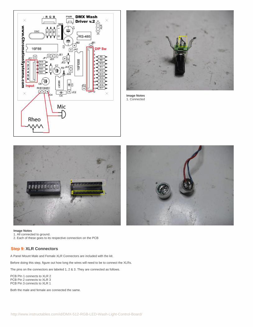
The RHEO&MIC is used for Sound Input Controls, the left hole is for the Rheostat, center hole is shared between one lead of the rheo and one lead of the MIC, right holeis for the MIC.
Sound Potentiometer - Adjusts Sound Reactive Sensitivity
- The potentiometer needs to be used as a Rheostat for this part.
- One of the outer leads on the potentiometer should be soldered to the center lead. See Image
- One lead goes to the Rheo Hole, the other connection goes to the shared center hole.
Microphone - Listens for sound input.
- The electret mic has 2 solder pads, One is soldered to the MIC hole and the other is soldered to the shared center hole.
DIP Switch - 9 Positions are used for DMX Address and One is used for Stand-Alone Control. All the positions are pulled-up with the 10k resistors. And are "ON" whenconnected to GND.
DIP1 on the PCB is Positive and not neededDIP2 is Ground, one side of the DIP switch will be wired to GroundDIP3 is Binary 1DIP4 is Binary 2DIP5 is Binary 4DIP6 is Binary 8DIP7 is Binary 16DIP8 is Binary 32DIP9 is Binary 64DIP10 is Binary 128DIP11 is Binary 256DIP12 is for Stand-Alone Mode Selection.
- There are 2 rows of pins on the DIP Switch, one side/half of the pins are all connected together and attached to Ground(DIP2 on the PCB)
- The other row of pins each needs to be connected to its proper place on the PCB.
http://www.instructables.com/id/DMX-512-RGB-LED-Wash-Light-Control-Board/
Image Notes1. Connected
Image Notes1. All connected to ground.2. Each of these goes to its respective connection on the PCB
Step 9: XLR Connectors
A Panel Mount Male and Female XLR Connectors are included with the kit.
Before doing this step, figure out how long the wires will need to be to connect the XLRs.
The pins on the connectors are labeled 1, 2 & 3. They are connected as follows.
PCB PIn 1 connects to XLR 2PCB Pin 2 connects to XLR 3PCB Pin 3 connects to XLR 1
Both the male and female are connected the same.

http://www.instructables.com/id/DMX-512-RGB-LED-Wash-Light-Control-Board/
Step 10: Plug in the ICs
There are 4 ICs to plug into their sockets. Line up the dot near pin 1 on each of the ICs with the notch on the end of the IC sockets.
- Align all the pins of each IC with their socket and press in firmly.
- Plug in all the ICs
Step 11: Breakout board and Testing
To power anything more substantial than a single RGB LED, a breakout board is used.
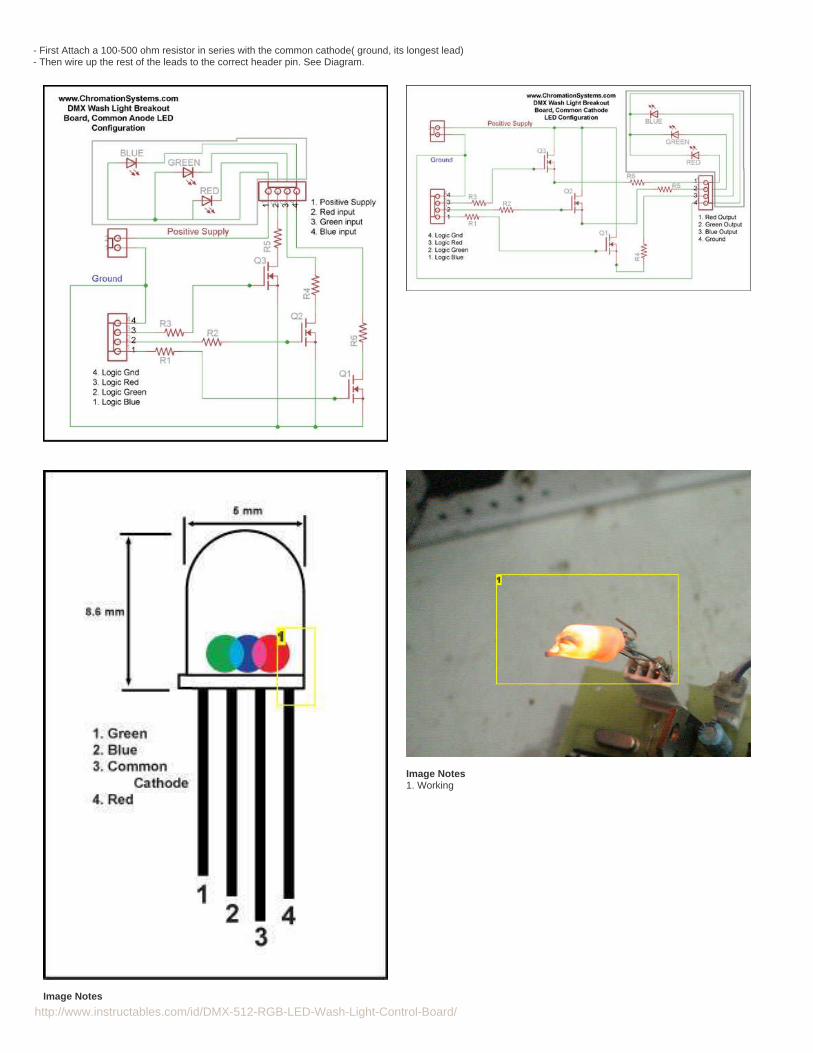
A board is chosen depending on the LED setup to be used. They come in Resistor regulated Common-Anode, Resistor regulated Common Cathode Configuration andConstant-Current Regulated board.
The Supplied Resistor Regulated boards are meant for multiple small LEDs or a few high-wattage LEDs, R4, R5, & R6 are large enough for a 2 or 3 watt Resistors.MOSFETs included with the boards can handle up to 46 watts each.
For very large units, I have had good success with the BuckPlus Line of constant current regulators. See Here
When ordering a kit, either decide what kind you will need or Contact Us for Help choosing.
Testing:
To test if the PCB is working properly attach the included Common Cathode RGB LED to the" - R G B" Header.
http://www.instructables.com/id/DMX-512-RGB-LED-Wash-Light-Control-Board/
- First Attach a 100-500 ohm resistor in series with the common cathode( ground, its longest lead)- Then wire up the rest of the leads to the correct header pin. See Diagram.
Image Notes
Image Notes1. Working
http://www.instructables.com/id/DMX-512-RGB-LED-Wash-Light-Control-Board/
1. Flat side
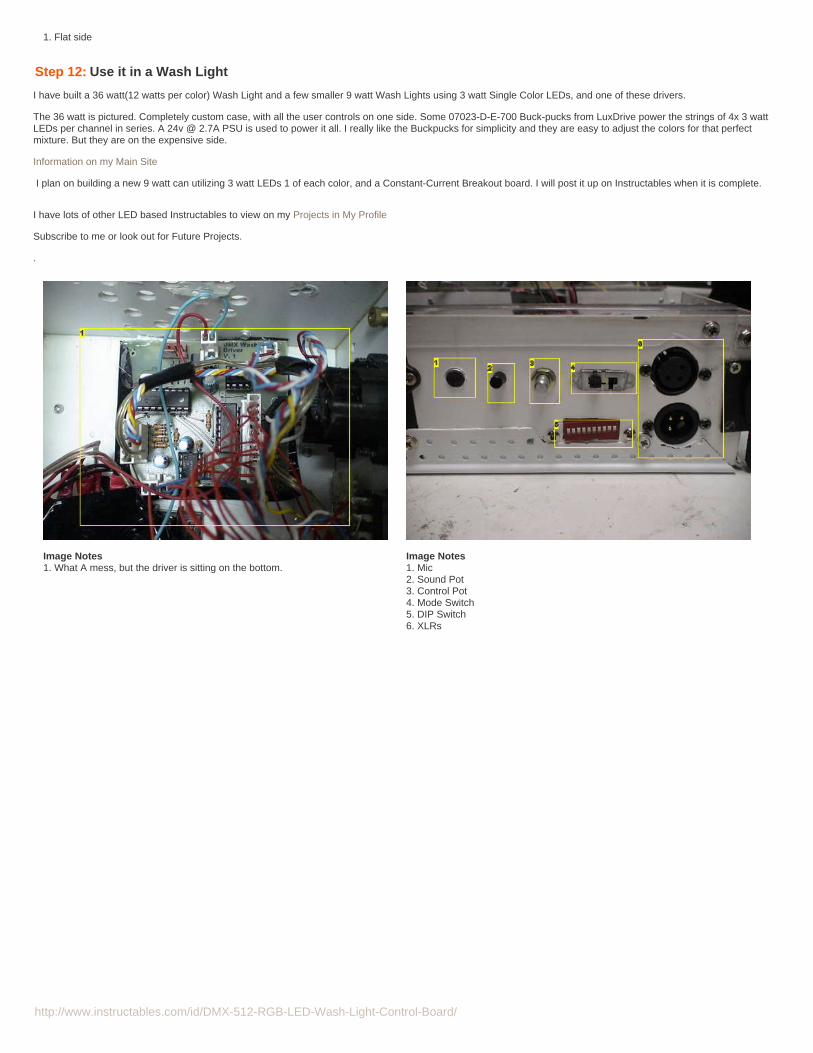
Step 12: Use it in a Wash Light
I have built a 36 watt(12 watts per color) Wash Light and a few smaller 9 watt Wash Lights using 3 watt Single Color LEDs, and one of these drivers.
The 36 watt is pictured. Completely custom case, with all the user controls on one side. Some 07023-D-E-700 Buck-pucks from LuxDrive power the strings of 4x 3 wattLEDs per channel in series. A 24v @ 2.7A PSU is used to power it all. I really like the Buckpucks for simplicity and they are easy to adjust the colors for that perfectmixture. But they are on the expensive side.
Information on my Main Site
I plan on building a new 9 watt can utilizing 3 watt LEDs 1 of each color, and a Constant-Current Breakout board. I will post it up on Instructables when it is complete.
I have lots of other LED based Instructables to view on my Projects in My Profile
Subscribe to me or look out for Future Projects.
.
Image Notes1. What A mess, but the driver is sitting on the bottom.
Image Notes1. Mic2. Sound Pot3. Control Pot4. Mode Switch5. DIP Switch6. XLRs