
DMX 221 - Grundfosnet.grundfos.com/Appl/WebCAPS/streamliterature/Grundfosliterature... · 5.1.1 DMX...
75
DMX 221 Dosing pump Installation and operating instructions GRUNDFOS INSTRUCTIONS
Transcript of DMX 221 - Grundfosnet.grundfos.com/Appl/WebCAPS/streamliterature/Grundfosliterature... · 5.1.1 DMX...
DMX 221Dosing pump
Installation and operating instructions
GRUNDFOS INSTRUCTIONS
Original installation and operating instructions
Table of contents1. General information . . . . . . . . . . . . . . . . . . . . . . . . . . . . . . . . . . . . . . . . . . . . . . . . . . . . . . . .31.1 Qualification and training. . . . . . . . . . . . . . . . . . . . . . . . . . . . . . . . . . . . . . . . . . . . . . . . . . . . .41.2 Symbols used in this document. . . . . . . . . . . . . . . . . . . . . . . . . . . . . . . . . . . . . . . . . . . . . . . .51.3 Symbols on the product. . . . . . . . . . . . . . . . . . . . . . . . . . . . . . . . . . . . . . . . . . . . . . . . . . . . . .5
2. Installing the product . . . . . . . . . . . . . . . . . . . . . . . . . . . . . . . . . . . . . . . . . . . . . . . . . . . . . .52.1 Location . . . . . . . . . . . . . . . . . . . . . . . . . . . . . . . . . . . . . . . . . . . . . . . . . . . . . . . . . . . . . . . . .6
2.1.1 Installation requirements . . . . . . . . . . . . . . . . . . . . . . . . . . . . . . . . . . . . . . . . . . . . . . . . .62.1.2 Installation tips . . . . . . . . . . . . . . . . . . . . . . . . . . . . . . . . . . . . . . . . . . . . . . . . . . . . . . . . .7
2.1.2.1 Installation with ball valve and non-return valve. . . . . . . . . . . . . . . . . . . . . . . . . . . . .72.1.2.2 Installation of the inlet line . . . . . . . . . . . . . . . . . . . . . . . . . . . . . . . . . . . . . . . . . . . . .82.1.2.3 Installation with pressure-relief valve. . . . . . . . . . . . . . . . . . . . . . . . . . . . . . . . . . . . .82.1.2.4 Installation on a tank . . . . . . . . . . . . . . . . . . . . . . . . . . . . . . . . . . . . . . . . . . . . . . . . .82.1.2.5 Siphon effect . . . . . . . . . . . . . . . . . . . . . . . . . . . . . . . . . . . . . . . . . . . . . . . . . . . . . . .92.1.2.6 Installation with pressure-loading valve . . . . . . . . . . . . . . . . . . . . . . . . . . . . . . . . . . .92.1.2.7 Installation with pulsation damper on the inlet side . . . . . . . . . . . . . . . . . . . . . . . . .102.1.2.8 Installation with pulsation damper on the outlet side . . . . . . . . . . . . . . . . . . . . . . . .10
2.2 Mechanical installation . . . . . . . . . . . . . . . . . . . . . . . . . . . . . . . . . . . . . . . . . . . . . . . . . . . .112.2.1 Mounting the pump . . . . . . . . . . . . . . . . . . . . . . . . . . . . . . . . . . . . . . . . . . . . . . . . . . . .112.2.2 Dosing head connections . . . . . . . . . . . . . . . . . . . . . . . . . . . . . . . . . . . . . . . . . . . . . . . .12
2.2.2.1 Connecting hoses . . . . . . . . . . . . . . . . . . . . . . . . . . . . . . . . . . . . . . . . . . . . . . . . . .122.2.2.2 Connecting pipes . . . . . . . . . . . . . . . . . . . . . . . . . . . . . . . . . . . . . . . . . . . . . . . . . .13
2.3 Electrical connection . . . . . . . . . . . . . . . . . . . . . . . . . . . . . . . . . . . . . . . . . . . . . . . . . . . . . .142.3.1 Safety instructions and requirements for electrical connection . . . . . . . . . . . . . . . . . . . .142.3.2 Making electrical connection with mains plug . . . . . . . . . . . . . . . . . . . . . . . . . . . . . . . . .142.3.3 Making electrical connection without mains plug . . . . . . . . . . . . . . . . . . . . . . . . . . . . . .14
3. Starting up the product . . . . . . . . . . . . . . . . . . . . . . . . . . . . . . . . . . . . . . . . . . . . . . . . . . . .143.1 Preparing the pump for startup . . . . . . . . . . . . . . . . . . . . . . . . . . . . . . . . . . . . . . . . . . . . . . .153.2 Safety instructions and requirements for startup . . . . . . . . . . . . . . . . . . . . . . . . . . . . . . . . . .153.3 Starting up the pump. . . . . . . . . . . . . . . . . . . . . . . . . . . . . . . . . . . . . . . . . . . . . . . . . . . . . . .163.4 Stopping and starting dosing . . . . . . . . . . . . . . . . . . . . . . . . . . . . . . . . . . . . . . . . . . . . . . . . .173.5 Deaerating the pump during operation . . . . . . . . . . . . . . . . . . . . . . . . . . . . . . . . . . . . . . . . .173.6 Adjusting the zero point. . . . . . . . . . . . . . . . . . . . . . . . . . . . . . . . . . . . . . . . . . . . . . . . . . . . .183.7 Adjusting the dosing flow via the stroke length . . . . . . . . . . . . . . . . . . . . . . . . . . . . . . . . . . .193.8 Adjustment of the stroke rate with a frequency converter . . . . . . . . . . . . . . . . . . . . . . . . . . .193.9 Opening and reactivating the integral relief valve . . . . . . . . . . . . . . . . . . . . . . . . . . . . . . . . .193.10 Setting the opening pressure of the integral relief valve . . . . . . . . . . . . . . . . . . . . . . . . . . .203.11 Operating the pump with electronics . . . . . . . . . . . . . . . . . . . . . . . . . . . . . . . . . . . . . . . . . .21
4. Handling and storing the product . . . . . . . . . . . . . . . . . . . . . . . . . . . . . . . . . . . . . . . . . . .214.1 Handling the product . . . . . . . . . . . . . . . . . . . . . . . . . . . . . . . . . . . . . . . . . . . . . . . . . . . . . . .224.2 Storing the product . . . . . . . . . . . . . . . . . . . . . . . . . . . . . . . . . . . . . . . . . . . . . . . . . . . . . . . .22
5. Product introduction . . . . . . . . . . . . . . . . . . . . . . . . . . . . . . . . . . . . . . . . . . . . . . . . . . . . . .225.1 Product description . . . . . . . . . . . . . . . . . . . . . . . . . . . . . . . . . . . . . . . . . . . . . . . . . . . . . . .23
5.1.1 DMX 221 components . . . . . . . . . . . . . . . . . . . . . . . . . . . . . . . . . . . . . . . . . . . . . . . . . .235.1.2 Functional principle of the pump. . . . . . . . . . . . . . . . . . . . . . . . . . . . . . . . . . . . . . . . . . .245.1.3 AR control unit . . . . . . . . . . . . . . . . . . . . . . . . . . . . . . . . . . . . . . . . . . . . . . . . . . . . . . . .245.1.4 Functional principle of the integral relief valve . . . . . . . . . . . . . . . . . . . . . . . . . . . . . . . .245.1.5 Stroke sensor . . . . . . . . . . . . . . . . . . . . . . . . . . . . . . . . . . . . . . . . . . . . . . . . . . . . . . . . .25
5.2 Applications . . . . . . . . . . . . . . . . . . . . . . . . . . . . . . . . . . . . . . . . . . . . . . . . . . . . . . . . . . . . .255.2.1 Intended use . . . . . . . . . . . . . . . . . . . . . . . . . . . . . . . . . . . . . . . . . . . . . . . . . . . . . . . . .255.2.2 Safety of the system in case of a failure in the dosing pump . . . . . . . . . . . . . . . . . . . . .25
5.3 Identification . . . . . . . . . . . . . . . . . . . . . . . . . . . . . . . . . . . . . . . . . . . . . . . . . . . . . . . . . . . .265.3.1 Nameplate . . . . . . . . . . . . . . . . . . . . . . . . . . . . . . . . . . . . . . . . . . . . . . . . . . . . . . . . . . .265.3.2 Type key. . . . . . . . . . . . . . . . . . . . . . . . . . . . . . . . . . . . . . . . . . . . . . . . . . . . . . . . . . . . .27
DMX 221 | Table of contents | 2
6. Taking the product out of operation . . . . . . . . . . . . . . . . . . . . . . . . . . . . . . . . . . . . . . . . . .30
7. Maintaining the product . . . . . . . . . . . . . . . . . . . . . . . . . . . . . . . . . . . . . . . . . . . . . . . . . . .317.1 Maintenance schedule . . . . . . . . . . . . . . . . . . . . . . . . . . . . . . . . . . . . . . . . . . . . . . . . . . . . .327.2 Safety instructions for maintaining the dosing diaphragm or the valves. . . . . . . . . . . . . . . . .337.3 Preparing for maintenance of the dosing diaphragm or the valves . . . . . . . . . . . . . . . . . . . .337.4 Cleaning or replacing the inlet and outlet valves . . . . . . . . . . . . . . . . . . . . . . . . . . . . . . . . . .347.5 Cleaning or replacing the dosing diaphragm . . . . . . . . . . . . . . . . . . . . . . . . . . . . . . . . . . . . .367.6 Cleaning or replacing the diaphragm of the integral relief valve. . . . . . . . . . . . . . . . . . . . . . .367.7 Returning the product . . . . . . . . . . . . . . . . . . . . . . . . . . . . . . . . . . . . . . . . . . . . . . . . . . . . . .37
8. Fault finding the product . . . . . . . . . . . . . . . . . . . . . . . . . . . . . . . . . . . . . . . . . . . . . . . . . .378.1 The dosing pump does not run . . . . . . . . . . . . . . . . . . . . . . . . . . . . . . . . . . . . . . . . . . . . . . .388.2 The dosing pump does not suck in . . . . . . . . . . . . . . . . . . . . . . . . . . . . . . . . . . . . . . . . . . . .388.3 No dosing flow . . . . . . . . . . . . . . . . . . . . . . . . . . . . . . . . . . . . . . . . . . . . . . . . . . . . . . . . . . .388.4 The dosing flow is inaccurate . . . . . . . . . . . . . . . . . . . . . . . . . . . . . . . . . . . . . . . . . . . . . . . .398.5 Permanent leakage from the integral relief valve. . . . . . . . . . . . . . . . . . . . . . . . . . . . . . . . . .398.6 The diaphragm leakage sensor does not operate properly . . . . . . . . . . . . . . . . . . . . . . . . . .39
9. Technical data . . . . . . . . . . . . . . . . . . . . . . . . . . . . . . . . . . . . . . . . . . . . . . . . . . . . . . . . . . .399.1 Ambient conditions . . . . . . . . . . . . . . . . . . . . . . . . . . . . . . . . . . . . . . . . . . . . . . . . . . . . . . . .409.2 Dosing medium . . . . . . . . . . . . . . . . . . . . . . . . . . . . . . . . . . . . . . . . . . . . . . . . . . . . . . . . . . .419.3 Mechanical data . . . . . . . . . . . . . . . . . . . . . . . . . . . . . . . . . . . . . . . . . . . . . . . . . . . . . . . . .42
9.3.1 Torque values. . . . . . . . . . . . . . . . . . . . . . . . . . . . . . . . . . . . . . . . . . . . . . . . . . . . . . . . .429.3.2 Housing materials . . . . . . . . . . . . . . . . . . . . . . . . . . . . . . . . . . . . . . . . . . . . . . . . . . . . .439.3.3 Pump performance. . . . . . . . . . . . . . . . . . . . . . . . . . . . . . . . . . . . . . . . . . . . . . . . . . . . .449.3.4 Suction lift . . . . . . . . . . . . . . . . . . . . . . . . . . . . . . . . . . . . . . . . . . . . . . . . . . . . . . . . . . .479.3.5 Sound pressure level . . . . . . . . . . . . . . . . . . . . . . . . . . . . . . . . . . . . . . . . . . . . . . . . . . .48
9.4 Electrical data . . . . . . . . . . . . . . . . . . . . . . . . . . . . . . . . . . . . . . . . . . . . . . . . . . . . . . . . . . . .499.5 Dimensions and weights . . . . . . . . . . . . . . . . . . . . . . . . . . . . . . . . . . . . . . . . . . . . . . . . . . .50
9.5.1 Dimensional sketch . . . . . . . . . . . . . . . . . . . . . . . . . . . . . . . . . . . . . . . . . . . . . . . . . . . .509.5.2 Weights . . . . . . . . . . . . . . . . . . . . . . . . . . . . . . . . . . . . . . . . . . . . . . . . . . . . . . . . . . . . .52
9.6 Dosing curves . . . . . . . . . . . . . . . . . . . . . . . . . . . . . . . . . . . . . . . . . . . . . . . . . . . . . . . . . . . .53
10. Disposing of the product . . . . . . . . . . . . . . . . . . . . . . . . . . . . . . . . . . . . . . . . . . . . . . . . .5310.1 Disposing of hazardous or toxic materials . . . . . . . . . . . . . . . . . . . . . . . . . . . . . . . . . . . . . .5410.2 Disposing of the product . . . . . . . . . . . . . . . . . . . . . . . . . . . . . . . . . . . . . . . . . . . . . . . . . . .54
11. Pump options and variants . . . . . . . . . . . . . . . . . . . . . . . . . . . . . . . . . . . . . . . . . . . . . . . .5411.1 Diaphragm leakage sensor . . . . . . . . . . . . . . . . . . . . . . . . . . . . . . . . . . . . . . . . . . . . . . . . .55
11.1.1 Function of the electronic unit for optical sensor . . . . . . . . . . . . . . . . . . . . . . . . . . . . . .5611.1.2 Mounting the electronic unit for optical sensor . . . . . . . . . . . . . . . . . . . . . . . . . . . . . . .5611.1.3 Electrical connection . . . . . . . . . . . . . . . . . . . . . . . . . . . . . . . . . . . . . . . . . . . . . . . . . .56
11.1.3.1 Connecting the diaphragm leakage sensor electrically with the AR control unit . . .5611.1.3.2 Connecting the diaphragm leakage sensor electrically with the electronic unit for
optical sensor . . . . . . . . . . . . . . . . . . . . . . . . . . . . . . . . . . . . . . . . . . . . . . . . . . . . . . . .5711.1.3.3 Interference suppression of inductive loads . . . . . . . . . . . . . . . . . . . . . . . . . . . . . .58
11.1.4 Checking the diaphragm leakage sensor . . . . . . . . . . . . . . . . . . . . . . . . . . . . . . . . . . .5911.1.5 Maintaining the diaphragm leakage sensor. . . . . . . . . . . . . . . . . . . . . . . . . . . . . . . . . .6011.1.6 Technical data of the electronic unit for optical sensor . . . . . . . . . . . . . . . . . . . . . . . . .60
11.1.6.1 Dimensional sketch of the electronic unit for optical sensor . . . . . . . . . . . . . . . . . .6011.2 Pumps with VFD . . . . . . . . . . . . . . . . . . . . . . . . . . . . . . . . . . . . . . . . . . . . . . . . . . . . . . . . .61
11.2.1 Identification of pumps with VFD . . . . . . . . . . . . . . . . . . . . . . . . . . . . . . . . . . . . . . . . .6111.2.2 Connecting the VFD to the power supply . . . . . . . . . . . . . . . . . . . . . . . . . . . . . . . . . . .6211.2.3 Operating modes . . . . . . . . . . . . . . . . . . . . . . . . . . . . . . . . . . . . . . . . . . . . . . . . . . . . .6411.2.4 Special VFD parameter settings for DMX . . . . . . . . . . . . . . . . . . . . . . . . . . . . . . . . . . .6511.2.5 Technical data of DMX pumps with VFD. . . . . . . . . . . . . . . . . . . . . . . . . . . . . . . . . . . .66
11.2.5.1 Dimensional sketch of DMX pumps with VFD . . . . . . . . . . . . . . . . . . . . . . . . . . . .66
DMX 221 | Table of contents | 3
1. General information
Read this document before you install the product. Installation and operationmust comply with local regulations and accepted codes of good practice.
Observe the instructions of optional components of the product.Observe the material safety data sheet of the dosing medium.Observe the installation and operating instructions supplied with the AR control unit, Servomotoror VFD in addition to the instructions in this manual.
• AR control unit: http://net.grundfos.com/qr/i/91834764• Servomotor: http://net.grundfos.com/qr/i/95721057• VFD supplier manual: https://www.nord.com.
Related information• 11.1 Diaphragm leakage sensor• 11.2 Pumps with VFD
1.1 Qualification and trainingThe persons responsible for installation, startup and service must be appropriately qualified forthese tasks.If the persons do not have the necessary knowledge, training and instruction must be given. Ifnecessary, training can be performed by the manufacturer or supplier on request.
DMX 221 | General information | 4
1.2 Symbols used in this document
DANGERIndicates a hazardous situation which, if not avoided, will result in death or seri-ous personal injury.
WARNINGIndicates a hazardous situation which, if not avoided, could result in death or se-rious personal injury.
CAUTIONIndicates a hazardous situation which, if not avoided, could result in minor ormoderate personal injury.
The text accompanying the three hazard symbols DANGER, WARNING and CAUTION is struc-tured in the following way:
SIGNAL WORDDescription of the hazardConsequence of ignoring the warningAction to avoid the hazard.
A blue or grey circle with a white graphical symbol indicates that an action mustbe taken.
If these instructions are not observed, it may result in malfunction or damage tothe equipment.
1.3 Symbols on the productInformation provided directly on the pump must be observed and maintained in a readable condi-tion at all times.
Symbol Description
Arrows on the inlet and outlet valves indicate the flow direction
An arrow on the motor indicates the direction of rotation
DMX 221 | General information | 5
2. Installing the product
2.1 Location• The product must be protected from direct sunlight and rain.• Make sure the ambient conditions match the enclosure class of the motor and the pump.• Install the product indoors if it has electronic components.• Provide enough space for maintenance and minimum 90 mm above the motor fan cover.• Observe all the ambient-condition requirements mentioned in the technical data section.• Observe the sections Installation requirements and Safety instructions and requirements for
startup.
Related information• 2.1.1 Installation requirements• 2.1.2 Installation tips
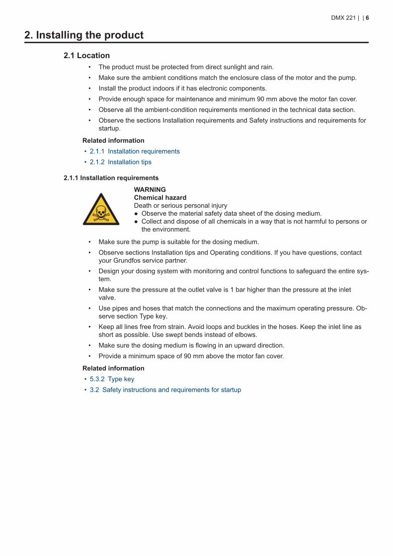
2.1.1 Installation requirements
WARNINGChemical hazardDeath or serious personal injury● Observe the material safety data sheet of the dosing medium.● Collect and dispose of all chemicals in a way that is not harmful to persons or
the environment.
• Make sure the pump is suitable for the dosing medium.• Observe sections Installation tips and Operating conditions. If you have questions, contact
your Grundfos service partner.• Design your dosing system with monitoring and control functions to safeguard the entire sys-
tem.• Make sure the pressure at the outlet valve is 1 bar higher than the pressure at the inlet
valve.• Use pipes and hoses that match the connections and the maximum operating pressure. Ob-
serve section Type key.• Keep all lines free from strain. Avoid loops and buckles in the hoses. Keep the inlet line as
short as possible. Use swept bends instead of elbows.• Make sure the dosing medium is flowing in an upward direction.• Provide a minimum space of 90 mm above the motor fan cover.
Related information• 5.3.2 Type key• 3.2 Safety instructions and requirements for startup
DMX 221 | | 6
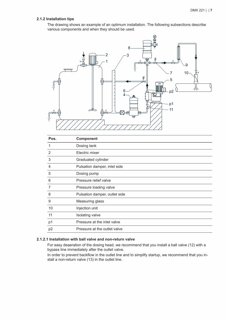
2.1.2 Installation tipsThe drawing shows an example of an optimum installation. The following subsections describevarious components and when they should be used.
2
1
8
3
64
7
5
9
10
11p1
p2
Pos. Component
1 Dosing tank
2 Electric mixer
3 Graduated cylinder
4 Pulsation damper, inlet side
5 Dosing pump
6 Pressure relief valve
7 Pressure loading valve
8 Pulsation damper, outlet side
9 Measuring glass
10 Injection unit
11 Isolating valve
p1 Pressure at the inlet valve
p2 Pressure at the outlet valve
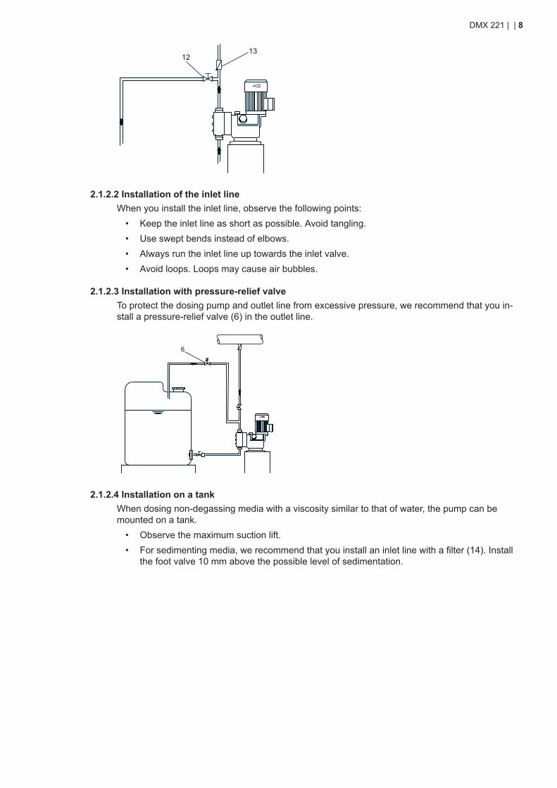
2.1.2.1 Installation with ball valve and non-return valveFor easy deaeration of the dosing head, we recommend that you install a ball valve (12) with abypass line immediately after the outlet valve.In order to prevent backflow in the outlet line and to simplify startup, we recommend that you in-stall a non-return valve (13) in the outlet line.
DMX 221 | | 7
1213
2.1.2.2 Installation of the inlet lineWhen you install the inlet line, observe the following points:
• Keep the inlet line as short as possible. Avoid tangling.• Use swept bends instead of elbows.• Always run the inlet line up towards the inlet valve.• Avoid loops. Loops may cause air bubbles.
2.1.2.3 Installation with pressure-relief valveTo protect the dosing pump and outlet line from excessive pressure, we recommend that you in-stall a pressure-relief valve (6) in the outlet line.
6
2.1.2.4 Installation on a tankWhen dosing non-degassing media with a viscosity similar to that of water, the pump can bemounted on a tank.
• Observe the maximum suction lift.• For sedimenting media, we recommend that you install an inlet line with a filter (14). Install
the foot valve 10 mm above the possible level of sedimentation.
DMX 221 | | 8
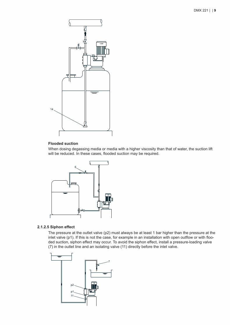
14
Flooded suctionWhen dosing degassing media or media with a higher viscosity than that of water, the suction liftwill be reduced. In these cases, flooded suction may be required.
6
2.1.2.5 Siphon effectThe pressure at the outlet valve (p2) must always be at least 1 bar higher than the pressure at theinlet valve (p1). If this is not the case, for example in an installation with open outflow or with floo-ded suction, siphon effect may occur. To avoid the siphon effect, install a pressure-loading valve(7) in the outlet line and an isolating valve (11) directly before the inlet valve.
7
p2
p111
DMX 221 | | 9
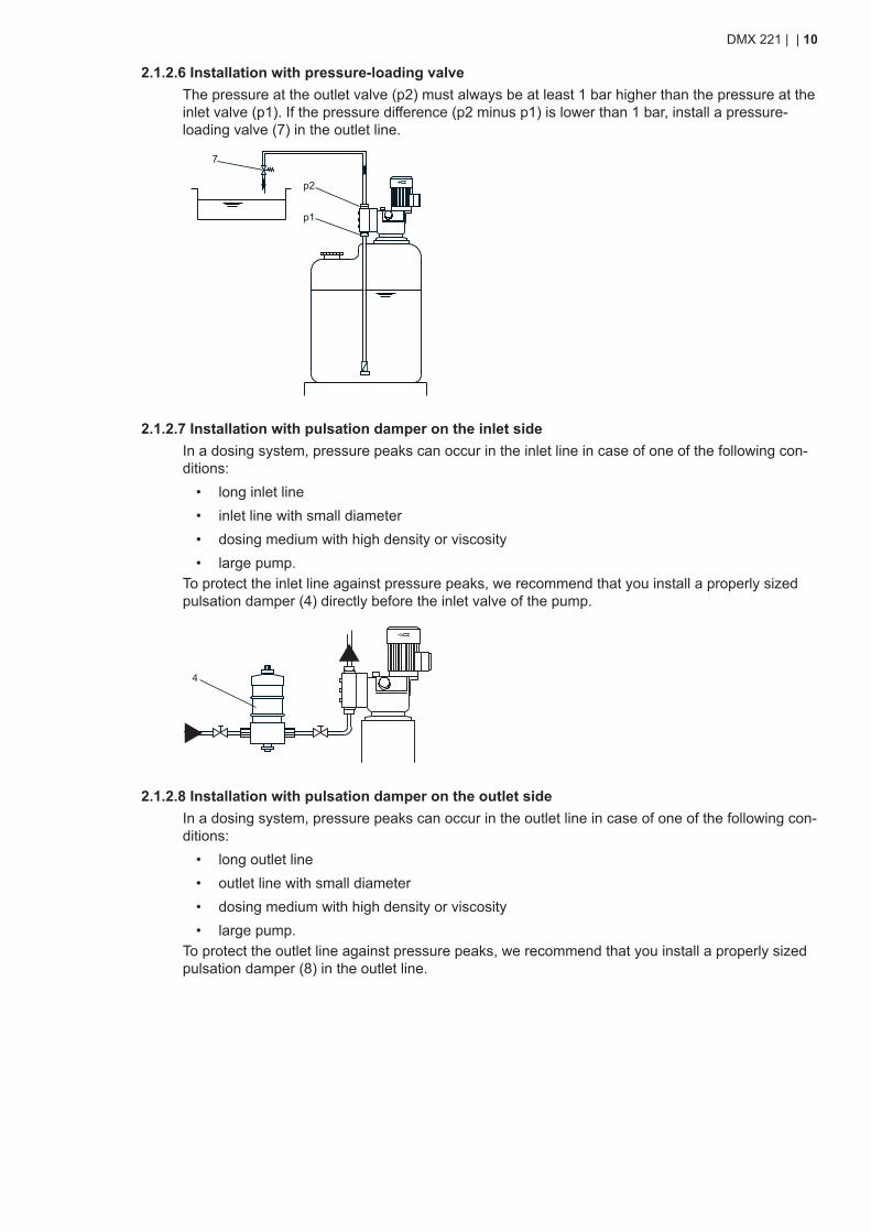
2.1.2.6 Installation with pressure-loading valveThe pressure at the outlet valve (p2) must always be at least 1 bar higher than the pressure at theinlet valve (p1). If the pressure difference (p2 minus p1) is lower than 1 bar, install a pressure-loading valve (7) in the outlet line.
7
p2
p1
2.1.2.7 Installation with pulsation damper on the inlet sideIn a dosing system, pressure peaks can occur in the inlet line in case of one of the following con-ditions:
• long inlet line• inlet line with small diameter• dosing medium with high density or viscosity• large pump.
To protect the inlet line against pressure peaks, we recommend that you install a properly sizedpulsation damper (4) directly before the inlet valve of the pump.
4
2.1.2.8 Installation with pulsation damper on the outlet sideIn a dosing system, pressure peaks can occur in the outlet line in case of one of the following con-ditions:
• long outlet line• outlet line with small diameter• dosing medium with high density or viscosity• large pump.
To protect the outlet line against pressure peaks, we recommend that you install a properly sizedpulsation damper (8) in the outlet line.
DMX 221 | | 10
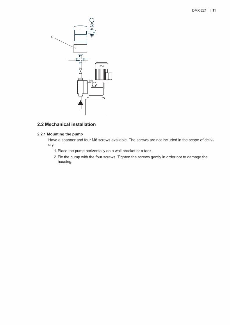
8
2.2 Mechanical installation
2.2.1 Mounting the pumpHave a spanner and four M6 screws available. The screws are not included in the scope of deliv-ery.
1. Place the pump horizontally on a wall bracket or a tank.2. Fix the pump with the four screws. Tighten the screws gently in order not to damage the
housing.
DMX 221 | | 11
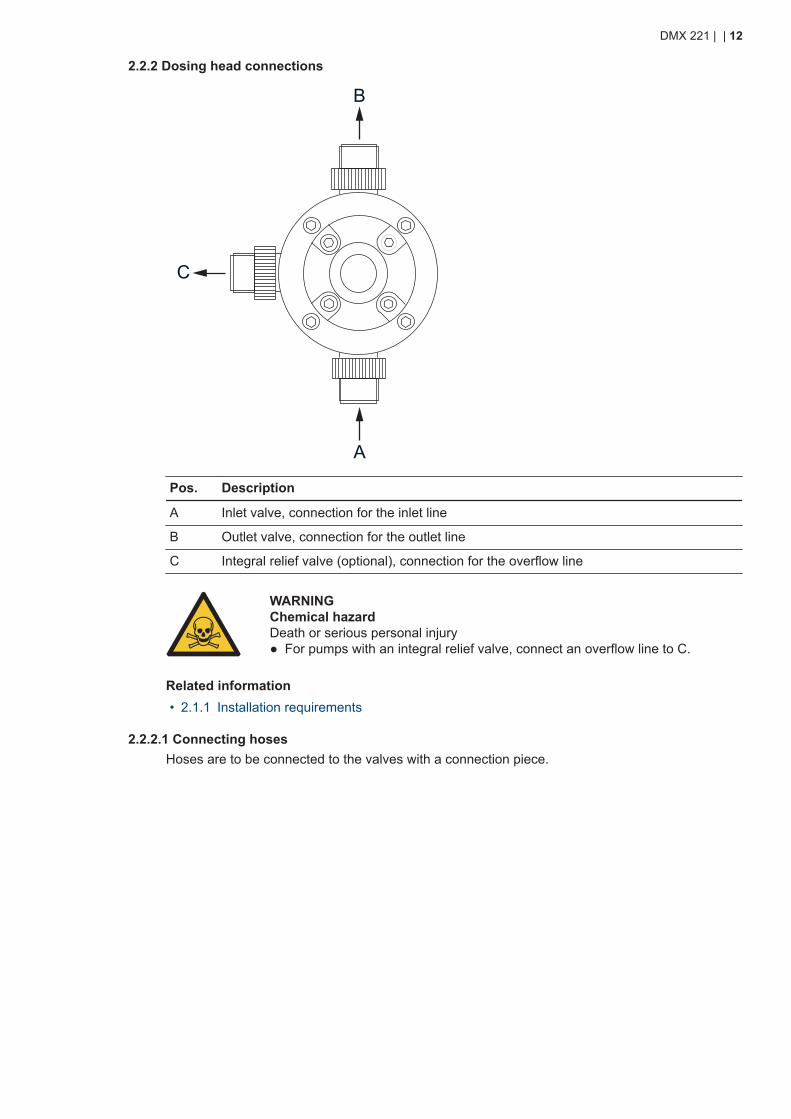
2.2.2 Dosing head connections
B
C
A
Pos. Description
A Inlet valve, connection for the inlet line
B Outlet valve, connection for the outlet line
C Integral relief valve (optional), connection for the overflow line
WARNINGChemical hazardDeath or serious personal injury● For pumps with an integral relief valve, connect an overflow line to C.
Related information• 2.1.1 Installation requirements
2.2.2.1 Connecting hosesHoses are to be connected to the valves with a connection piece.
DMX 221 | | 12
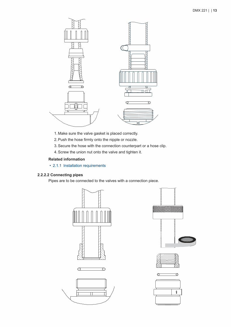
1. Make sure the valve gasket is placed correctly.2. Push the hose firmly onto the nipple or nozzle.3. Secure the hose with the connection counterpart or a hose clip.4. Screw the union nut onto the valve and tighten it.
Related information• 2.1.1 Installation requirements
2.2.2.2 Connecting pipesPipes are to be connected to the valves with a connection piece.
DMX 221 | | 13
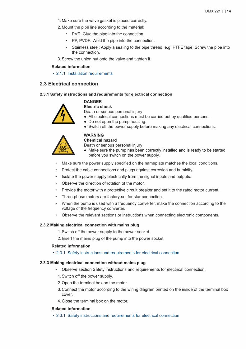
1. Make sure the valve gasket is placed correctly.2. Mount the pipe line according to the material:
• PVC: Glue the pipe into the connection.• PP, PVDF: Weld the pipe into the connection.• Stainless steel: Apply a sealing to the pipe thread, e.g. PTFE tape. Screw the pipe into
the connection.3. Screw the union nut onto the valve and tighten it.
Related information• 2.1.1 Installation requirements
2.3 Electrical connection
2.3.1 Safety instructions and requirements for electrical connection
DANGERElectric shockDeath or serious personal injury● All electrical connections must be carried out by qualified persons.● Do not open the pump housing.● Switch off the power supply before making any electrical connections.
WARNINGChemical hazardDeath or serious personal injury● Make sure the pump has been correctly installed and is ready to be started
before you switch on the power supply.
• Make sure the power supply specified on the nameplate matches the local conditions.• Protect the cable connections and plugs against corrosion and humidity.• Isolate the power supply electrically from the signal inputs and outputs.• Observe the direction of rotation of the motor.• Provide the motor with a protective circuit breaker and set it to the rated motor current.• Three-phase motors are factory-set for star connection.• When the pump is used with a frequency converter, make the connection according to the
voltage of the frequency converter.• Observe the relevant sections or instructions when connecting electronic components.
2.3.2 Making electrical connection with mains plug1. Switch off the power supply to the power socket.2. Insert the mains plug of the pump into the power socket.
Related information• 2.3.1 Safety instructions and requirements for electrical connection
2.3.3 Making electrical connection without mains plug• Observe section Safety instructions and requirements for electrical connection.
1. Switch off the power supply.2. Open the terminal box on the motor.3. Connect the motor according to the wiring diagram printed on the inside of the terminal box
cover.4. Close the terminal box on the motor.
Related information• 2.3.1 Safety instructions and requirements for electrical connection
DMX 221 | | 14
3. Starting up the product
3.1 Preparing the pump for startup• Observe section Safety instructions and requirements for startup.• Make sure the pump has been connected electrically by a qualified person.• Make sure the power supply specified on the nameplate matches the local conditions.• Check that all pipe or hose connections have been tightened properly and tighten them, if
necessary.• Check that the dosing head screws have been tightened with the specified torque and tight-
en them, if necessary.• Check that the vent plug on the pump housing is open.• For pumps with integral relief valve: Check that the overflow line is connected properly to the
integral relief valve.• For pumps with diaphragm leakage sensor: Check that the diaphragm leakage sensor is
functioning correctly.
Related information• 3.2 Safety instructions and requirements for startup• 3.3 Starting up the pump• 11.1.4 Checking the diaphragm leakage sensor
3.2 Safety instructions and requirements for startupWARNINGChemical hazardDeath or serious personal injury● Observe the material safety data sheet of the dosing medium.● Wear protective clothing when working on the dosing head, connections or
lines.● Collect and dispose of all chemicals in a way that is not harmful to persons or
the environment.● Make sure the pump has been correctly installed and is ready to be started
before you switch on the power supply.
WARNINGChemical hazardDeath or serious personal injury● Tighten the dosing head screws after initial startup and every time the dosing
head has been opened. After 6-10 operating hours or two days, retighten thedosing head screws using a torque wrench.
• The vent plug must be open while the pump is running.• Only adjust the stroke length while the pump is running.
DMX 221 | | 15
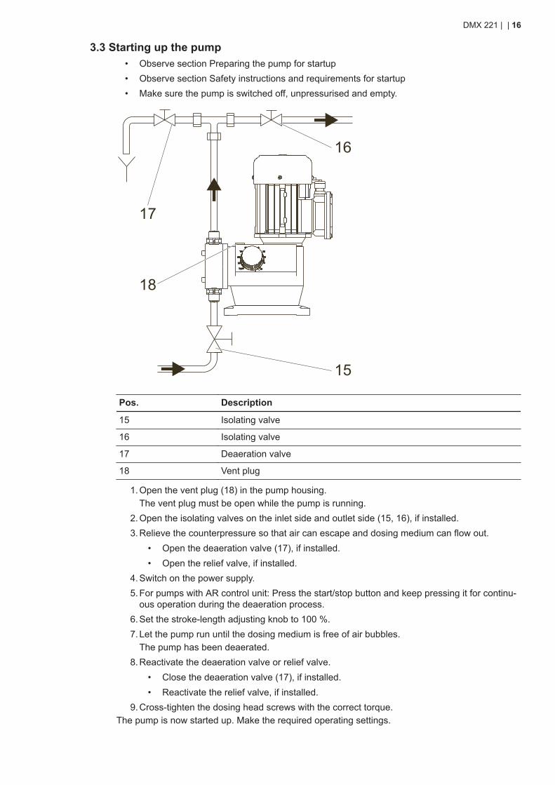
3.3 Starting up the pump• Observe section Preparing the pump for startup• Observe section Safety instructions and requirements for startup• Make sure the pump is switched off, unpressurised and empty.
16
17
15
18
Pos. Description
15 Isolating valve
16 Isolating valve
17 Deaeration valve
18 Vent plug
1. Open the vent plug (18) in the pump housing.The vent plug must be open while the pump is running.
2. Open the isolating valves on the inlet side and outlet side (15, 16), if installed.3. Relieve the counterpressure so that air can escape and dosing medium can flow out.
• Open the deaeration valve (17), if installed.• Open the relief valve, if installed.
4. Switch on the power supply.5. For pumps with AR control unit: Press the start/stop button and keep pressing it for continu-
ous operation during the deaeration process.6. Set the stroke-length adjusting knob to 100 %.7. Let the pump run until the dosing medium is free of air bubbles.
The pump has been deaerated.8. Reactivate the deaeration valve or relief valve.
• Close the deaeration valve (17), if installed.• Reactivate the relief valve, if installed.
9. Cross-tighten the dosing head screws with the correct torque.The pump is now started up. Make the required operating settings.
DMX 221 | | 16
Related information• 3.1 Preparing the pump for startup• 3.2 Safety instructions and requirements for startup• 3.9 Opening and reactivating the integral relief valve
3.4 Stopping and starting dosingMake sure the pump was installed and started up correctly.
1. To stop dosing:• For pumps with AR control unit, press the start/stop button.• Switch off the power supply.
2. To start dosing:• Switch on the power supply.• For pumps with AR control unit, press the start/stop button.
Related information• 3.1 Preparing the pump for startup• 3.3 Starting up the pump
3.5 Deaerating the pump during operationMake sure the pump was installed and started up correctly.
WARNINGChemical hazardDeath or serious personal injury● Wear protective clothing when working on the dosing head, connections or
lines.● Before relieving the pressure from the outlet side, make sure escaping dosing
medium cannot cause any harm to persons or equipment.● Collect and dispose of all chemicals in a way that is not harmful to persons or
the environment.
1. Relieve the counterpressure so that air can escape and dosing medium can flow out.• Open the deaeration valve (17), if installed.• Open the relief valve, if installed.
2. Switch on the power supply.3. For pumps with AR control unit: Press the start/stop button and keep pressing it for continu-
ous operation during the deaeration process.4. Set the stroke-length adjusting knob to 100 %.5. Let the pump run until the dosing medium is free of air bubbles.
The pump has been deaerated.6. Reactivate the deaeration valve or relief valve.
• Close the deaeration valve (17), if installed.• Reactivate the relief valve, if installed.
7. Change back to operating settings of the pump.
Related information• 3.3 Starting up the pump• 3.4 Stopping and starting dosing• 9.3.1 Torque values
DMX 221 | | 17
3.6 Adjusting the zero pointMake sure the pump was installed and started up correctly.
WARNINGChemical hazardDeath or serious personal injury● Wear protective clothing when working on the dosing head, connections or
lines.● Collect and dispose of all chemicals in a way that is not harmful to persons or
the environment.
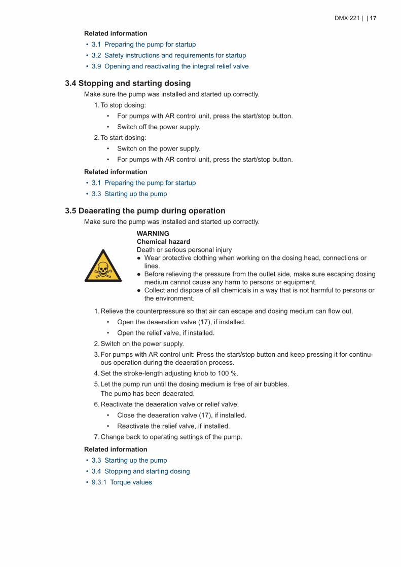
Only adjust the stroke length while the pump is running.
100%
90
80
70
60 50 40
30
20
10
0
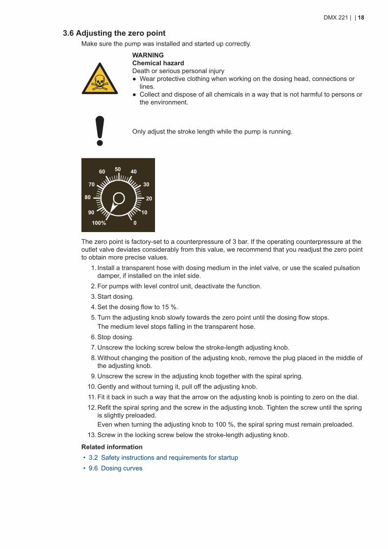
The zero point is factory-set to a counterpressure of 3 bar. If the operating counterpressure at theoutlet valve deviates considerably from this value, we recommend that you readjust the zero pointto obtain more precise values.
1. Install a transparent hose with dosing medium in the inlet valve, or use the scaled pulsationdamper, if installed on the inlet side.
2. For pumps with level control unit, deactivate the function.3. Start dosing.4. Set the dosing flow to 15 %.5. Turn the adjusting knob slowly towards the zero point until the dosing flow stops.
The medium level stops falling in the transparent hose.6. Stop dosing.7. Unscrew the locking screw below the stroke-length adjusting knob.8. Without changing the position of the adjusting knob, remove the plug placed in the middle of
the adjusting knob.9. Unscrew the screw in the adjusting knob together with the spiral spring.
10. Gently and without turning it, pull off the adjusting knob.11. Fit it back in such a way that the arrow on the adjusting knob is pointing to zero on the dial.12. Refit the spiral spring and the screw in the adjusting knob. Tighten the screw until the spring
is slightly preloaded.Even when turning the adjusting knob to 100 %, the spiral spring must remain preloaded.
13. Screw in the locking screw below the stroke-length adjusting knob.
Related information• 3.2 Safety instructions and requirements for startup• 9.6 Dosing curves
DMX 221 | | 18
3.7 Adjusting the dosing flow via the stroke lengthMake sure the pump was installed and started up correctly.
Only adjust the stroke length while the pump is running.
• To increase the dosing flow, turn the adjusting knob slowly to the left.• To decrease the dosing flow, turn the adjusting knob slowly to the right.
Related information• 3.2 Safety instructions and requirements for startup• 5.1.1 DMX 221 components• 5.1.2 Functional principle of the pump• 9.6 Dosing curves
3.8 Adjustment of the stroke rate with a frequency converterIf a frequency converter is connected, the dosing flow can be adjusted by changing the strokerate. This can only be done in the range of 10-100 % of the maximum stroke rate.For more information, read the installation and operating instructions of the frequency converter.
Related information• 11.2 Pumps with VFD
3.9 Opening and reactivating the integral relief valve• Make sure the pump was installed and started up correctly.• Make sure the pump is running during this task.
WARNINGChemical hazardDeath or serious personal injury● Wear protective clothing when working on the dosing head, connections or
lines.● Collect and dispose of all chemicals in a way that is not harmful to persons or
the environment.
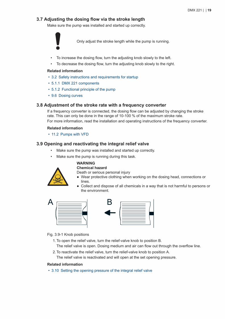
A B
Fig. 3.9-1 Knob positions1. To open the relief valve, turn the relief-valve knob to position B.
The relief valve is open. Dosing medium and air can flow out through the overflow line.2. To reactivate the relief valve, turn the relief-valve knob to position A.
The relief valve is reactivated and will open at the set opening pressure.
Related information• 3.10 Setting the opening pressure of the integral relief valve
DMX 221 | | 19
3.10 Setting the opening pressure of the integral relief valve• Make sure a pressure gauge is installed between the pump and an isolating valve in the out-
let line.• Make sure the pump was installed and started up correctly.• Make sure the pump is running during this task.
WARNINGChemical hazardDeath or serious personal injury● Do not set the opening pressure higher than the maximum counterpressure of
the pump.● Wear protective clothing when working on the dosing head, connections or
lines.● Collect and dispose of all chemicals in a way that is not harmful to persons or
the environment.
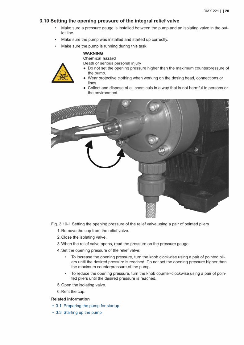
Fig. 3.10-1 Setting the opening pressure of the relief valve using a pair of pointed pliers1. Remove the cap from the relief valve.2. Close the isolating valve.3. When the relief valve opens, read the pressure on the pressure gauge.4. Set the opening pressure of the relief valve:
• To increase the opening pressure, turn the knob clockwise using a pair of pointed pli-ers until the desired pressure is reached. Do not set the opening pressure higher thanthe maximum counterpressure of the pump.
• To reduce the opening pressure, turn the knob counter-clockwise using a pair of poin-ted pliers until the desired pressure is reached.
5. Open the isolating valve.6. Refit the cap.
Related information• 3.1 Preparing the pump for startup• 3.3 Starting up the pump
DMX 221 | | 20
3.11 Operating the pump with electronicsObserve the installation and operating instructions supplied with the AR control unit, Servomotoror VFD in addition to the instructions in this manual.
• AR control unit: http://net.grundfos.com/qr/i/91834764• Servomotor: http://net.grundfos.com/qr/i/95721057• VFD supplier manual: https://www.nord.com
Related information• 11.1 Diaphragm leakage sensor• 11.2 Pumps with VFD
DMX 221 | | 21
4. Handling and storing the product
4.1 Handling the product
Close the vent plug when taking the pump out of operation for transport, storageor service.
• Retain the packaging for future storage or transport, or dispose of the packaging in accord-ance with local regulations.The packaging depends on the pump type and the scope of delivery.
• Make sure the product is suitably protected during transport and intermediate storage.• Keep the product in an upright position.• Do not throw or drop the product.
4.2 Storing the product
Close the vent plug when taking the pump out of operation for transport, storageor service.
• Store the pump in an upright position so that the grease cannot leak out.• Store the pump in a dry and clean place.• Observe the permissible ambient conditions.
Related information• 9.1 Ambient conditions
DMX 221 | | 22
5. Product introduction
5.1 Product description
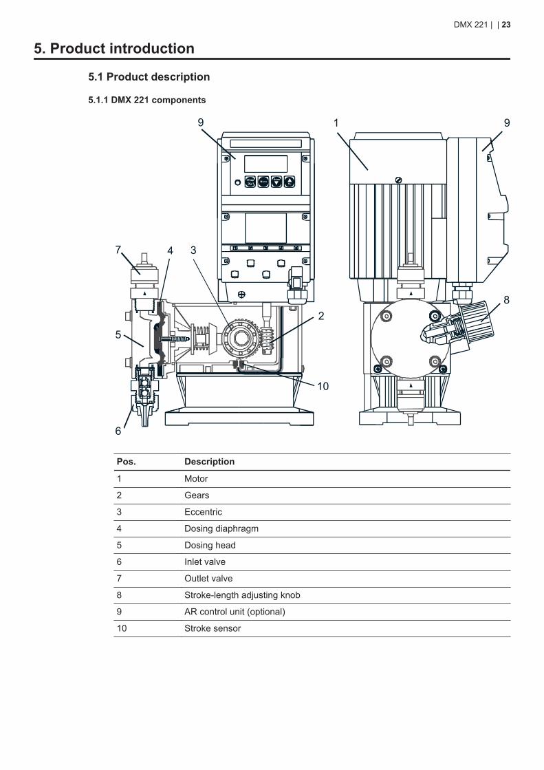
5.1.1 DMX 221 components
1
2
34
5
6
7
8
9
10
9
Pos. Description
1 Motor
2 Gears
3 Eccentric
4 Dosing diaphragm
5 Dosing head
6 Inlet valve
7 Outlet valve
8 Stroke-length adjusting knob
9 AR control unit (optional)
10 Stroke sensor
DMX 221 | | 23
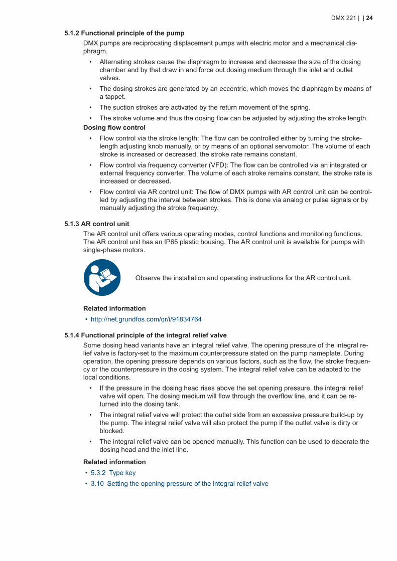
5.1.2 Functional principle of the pumpDMX pumps are reciprocating displacement pumps with electric motor and a mechanical dia-phragm.
• Alternating strokes cause the diaphragm to increase and decrease the size of the dosingchamber and by that draw in and force out dosing medium through the inlet and outletvalves.
• The dosing strokes are generated by an eccentric, which moves the diaphragm by means ofa tappet.
• The suction strokes are activated by the return movement of the spring.• The stroke volume and thus the dosing flow can be adjusted by adjusting the stroke length.
Dosing flow control• Flow control via the stroke length: The flow can be controlled either by turning the stroke-
length adjusting knob manually, or by means of an optional servomotor. The volume of eachstroke is increased or decreased, the stroke rate remains constant.
• Flow control via frequency converter (VFD): The flow can be controlled via an integrated orexternal frequency converter. The volume of each stroke remains constant, the stroke rate isincreased or decreased.
• Flow control via AR control unit: The flow of DMX pumps with AR control unit can be control-led by adjusting the interval between strokes. This is done via analog or pulse signals or bymanually adjusting the stroke frequency.
5.1.3 AR control unitThe AR control unit offers various operating modes, control functions and monitoring functions.The AR control unit has an IP65 plastic housing. The AR control unit is available for pumps withsingle-phase motors.
Observe the installation and operating instructions for the AR control unit.
Related information• http://net.grundfos.com/qr/i/91834764
5.1.4 Functional principle of the integral relief valveSome dosing head variants have an integral relief valve. The opening pressure of the integral re-lief valve is factory-set to the maximum counterpressure stated on the pump nameplate. Duringoperation, the opening pressure depends on various factors, such as the flow, the stroke frequen-cy or the counterpressure in the dosing system. The integral relief valve can be adapted to thelocal conditions.
• If the pressure in the dosing head rises above the set opening pressure, the integral reliefvalve will open. The dosing medium will flow through the overflow line, and it can be re-turned into the dosing tank.
• The integral relief valve will protect the outlet side from an excessive pressure build-up bythe pump. The integral relief valve will also protect the pump if the outlet valve is dirty orblocked.
• The integral relief valve can be opened manually. This function can be used to deaerate thedosing head and the inlet line.
Related information• 5.3.2 Type key• 3.10 Setting the opening pressure of the integral relief valve
DMX 221 | | 24
5.1.5 Stroke sensorThe stroke sensor is a two-wire inductive proximity switch for signalling the strokes.
• Sensor type: PNP• Supply voltage UB: 10-30 V
• Switching function: NO (Normally Open) contact.
5.2 Applications
5.2.1 Intended useDMX 221 pumps are suitable for dosing liquid, non-flammable and non-combustible media strictlyin accordance with these installation and operating instructions. Do not use DMX 221 pumps inpotentially explosive environments.DMX dosing pumps can only be operated in a safe and effective way, if they are installed properlyand the required ambient conditions are provided. Observe sections Location and Technical data.Incorrect use
• The operational safety of the pump is only ensured if it is used in accordance with sectionIntended use.
• The limit values specified in section Technical data must not be exceeded.• The pump is not approved for operation in potentially explosive areas.
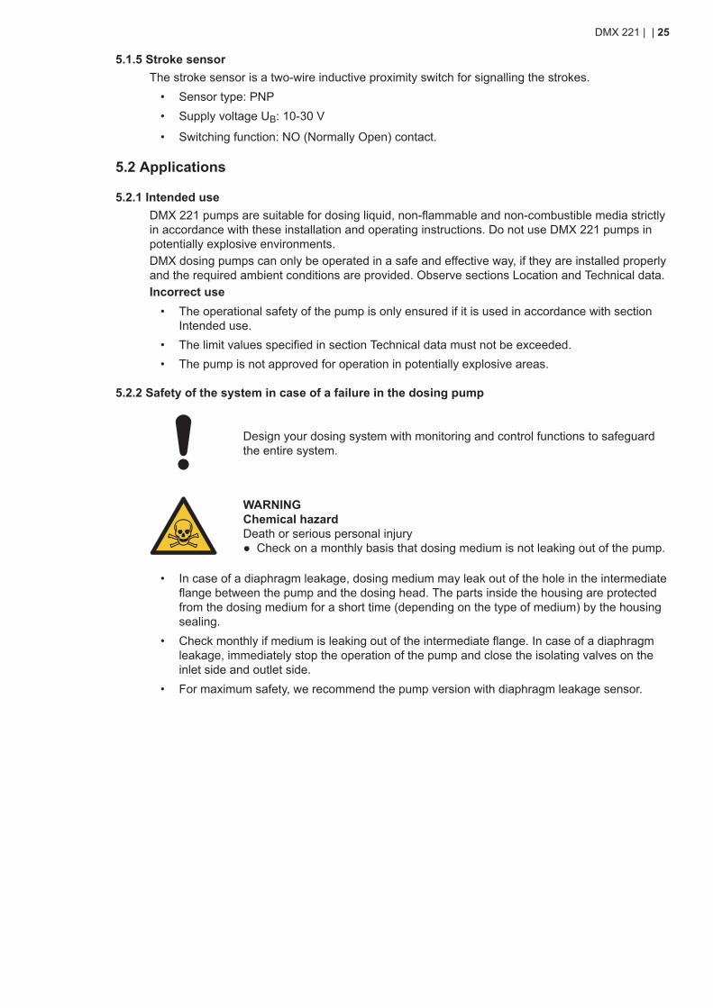
5.2.2 Safety of the system in case of a failure in the dosing pump
Design your dosing system with monitoring and control functions to safeguardthe entire system.
WARNINGChemical hazardDeath or serious personal injury● Check on a monthly basis that dosing medium is not leaking out of the pump.
• In case of a diaphragm leakage, dosing medium may leak out of the hole in the intermediateflange between the pump and the dosing head. The parts inside the housing are protectedfrom the dosing medium for a short time (depending on the type of medium) by the housingsealing.
• Check monthly if medium is leaking out of the intermediate flange. In case of a diaphragmleakage, immediately stop the operation of the pump and close the isolating valves on theinlet side and outlet side.
• For maximum safety, we recommend the pump version with diaphragm leakage sensor.
DMX 221 | | 25
5.3 Identification
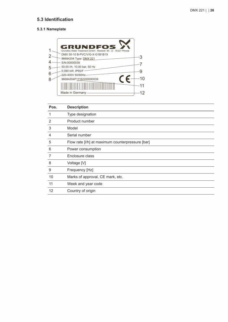
5.3.1 Nameplate
DMX 50-10 B-PVC/V/G-X-G1B1B1X96684204 Type: DMX 221S/N:0000003950,00 l/h, 10,00 bar, 50 Hz0,090 kW, IP65/F220-400V 50/60Hz96684204P11162200000039
Made in Germany
1
56
12
379
11
24
10
Grundfos Water Treatment GmbH - Reetzstr. 85 - D - 76327 Pfinztal
8
Pos. Description
1 Type designation
2 Product number
3 Model
4 Serial number
5 Flow rate [l/h] at maximum counterpressure [bar]
6 Power consumption
7 Enclosure class
8 Voltage [V]
9 Frequency [Hz]
10 Marks of approval, CE mark, etc.
11 Week and year code
12 Country of origin
DMX 221 | | 26
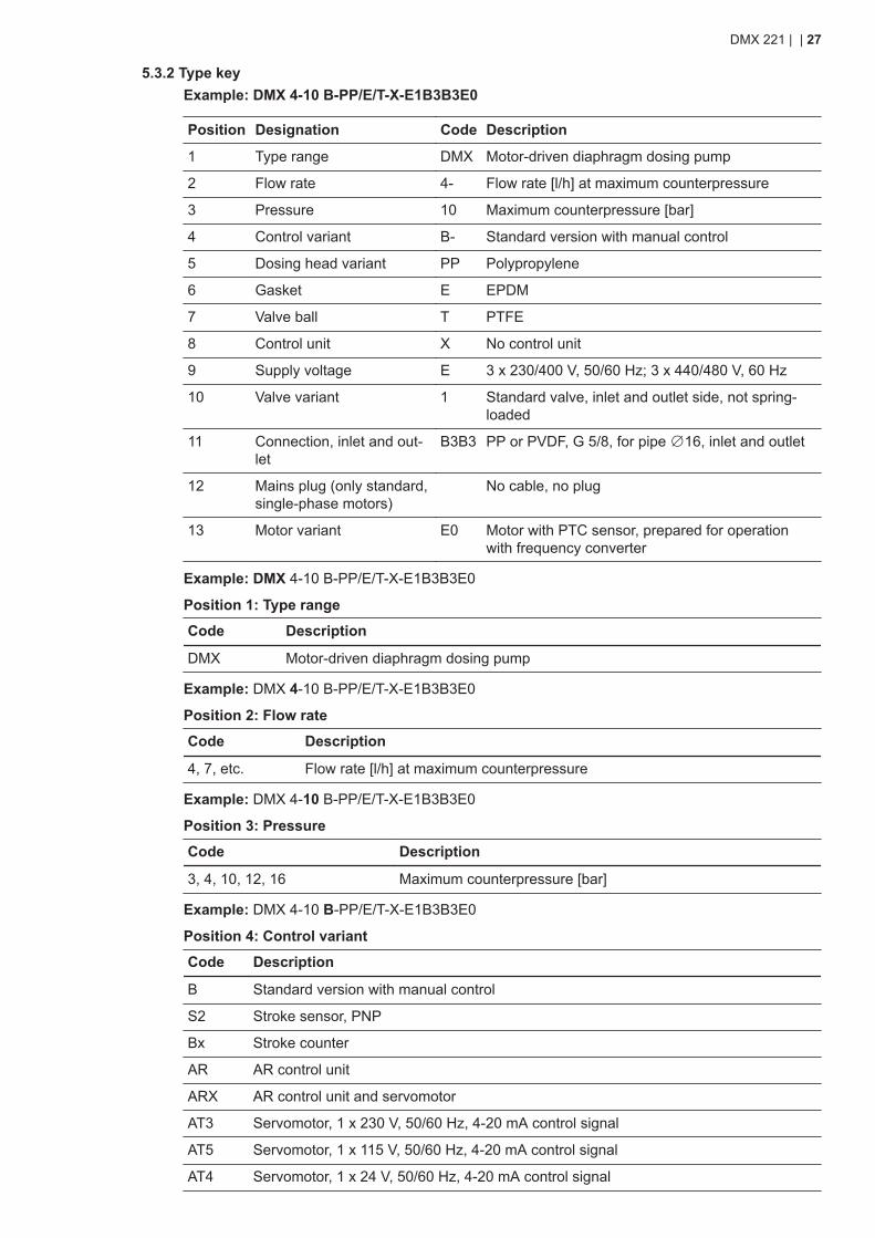
5.3.2 Type keyExample: DMX 4-10 B-PP/E/T-X-E1B3B3E0
Position Designation Code Description
1 Type range DMX Motor-driven diaphragm dosing pump
2 Flow rate 4- Flow rate [l/h] at maximum counterpressure
3 Pressure 10 Maximum counterpressure [bar]
4 Control variant B- Standard version with manual control
5 Dosing head variant PP Polypropylene
6 Gasket E EPDM
7 Valve ball T PTFE
8 Control unit X No control unit
9 Supply voltage E 3 x 230/400 V, 50/60 Hz; 3 x 440/480 V, 60 Hz
10 Valve variant 1 Standard valve, inlet and outlet side, not spring-loaded
11 Connection, inlet and out-let
B3B3 PP or PVDF, G 5/8, for pipe ∅16, inlet and outlet
12 Mains plug (only standard,single-phase motors)
No cable, no plug
13 Motor variant E0 Motor with PTC sensor, prepared for operationwith frequency converter
Example: DMX 4-10 B-PP/E/T-X-E1B3B3E0
Position 1: Type range
Code Description
DMX Motor-driven diaphragm dosing pump
Example: DMX 4-10 B-PP/E/T-X-E1B3B3E0
Position 2: Flow rate
Code Description
4, 7, etc. Flow rate [l/h] at maximum counterpressure
Example: DMX 4-10 B-PP/E/T-X-E1B3B3E0
Position 3: Pressure
Code Description
3, 4, 10, 12, 16 Maximum counterpressure [bar]
Example: DMX 4-10 B-PP/E/T-X-E1B3B3E0
Position 4: Control variant
Code Description
B Standard version with manual control
S2 Stroke sensor, PNP
Bx Stroke counter
AR AR control unit
ARX AR control unit and servomotor
AT3 Servomotor, 1 x 230 V, 50/60 Hz, 4-20 mA control signal
AT5 Servomotor, 1 x 115 V, 50/60 Hz, 4-20 mA control signal
AT4 Servomotor, 1 x 24 V, 50/60 Hz, 4-20 mA control signal
DMX 221 | | 27
Code Description
AT8 Servomotor, 1 x 230 V, 50/60 Hz, 1 KΩ potentiometer control
AT9 Servomotor, 1 x 115 V, 50/60 Hz, 1 KΩ potentiometer control
ATP Servomotor, 1 x 24 V, 50/60 Hz, 1 KΩ potentiometer control
Example: DMX 4-10 B-PP/E/T-X-E1B3B3E0
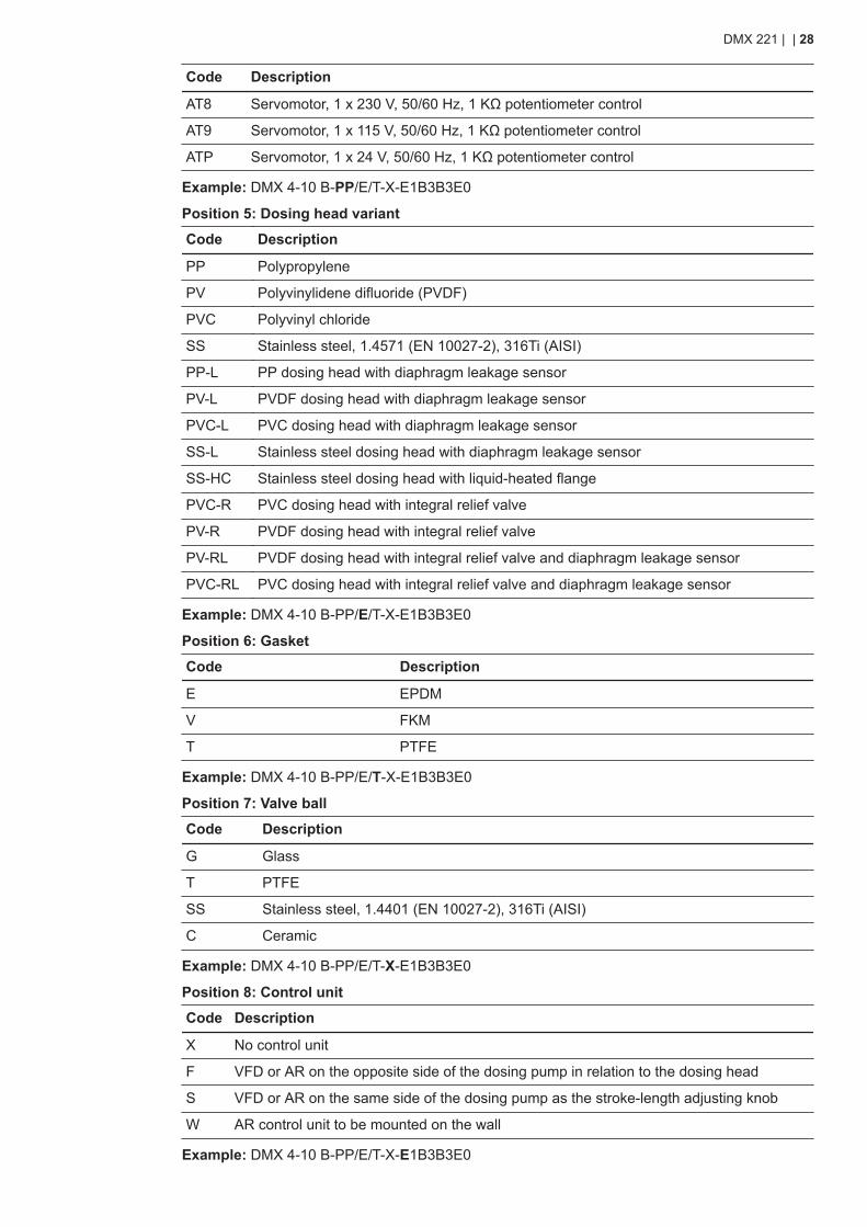
Position 5: Dosing head variant
Code Description
PP Polypropylene
PV Polyvinylidene difluoride (PVDF)
PVC Polyvinyl chloride
SS Stainless steel, 1.4571 (EN 10027-2), 316Ti (AISI)
PP-L PP dosing head with diaphragm leakage sensor
PV-L PVDF dosing head with diaphragm leakage sensor
PVC-L PVC dosing head with diaphragm leakage sensor
SS-L Stainless steel dosing head with diaphragm leakage sensor
SS-HC Stainless steel dosing head with liquid-heated flange
PVC-R PVC dosing head with integral relief valve
PV-R PVDF dosing head with integral relief valve
PV-RL PVDF dosing head with integral relief valve and diaphragm leakage sensor
PVC-RL PVC dosing head with integral relief valve and diaphragm leakage sensor
Example: DMX 4-10 B-PP/E/T-X-E1B3B3E0
Position 6: Gasket
Code Description
E EPDM
V FKM
T PTFE
Example: DMX 4-10 B-PP/E/T-X-E1B3B3E0
Position 7: Valve ball
Code Description
G Glass
T PTFE
SS Stainless steel, 1.4401 (EN 10027-2), 316Ti (AISI)
C Ceramic
Example: DMX 4-10 B-PP/E/T-X-E1B3B3E0
Position 8: Control unit
Code Description
X No control unit
F VFD or AR on the opposite side of the dosing pump in relation to the dosing head
S VFD or AR on the same side of the dosing pump as the stroke-length adjusting knob
W AR control unit to be mounted on the wall
Example: DMX 4-10 B-PP/E/T-X-E1B3B3E0
DMX 221 | | 28
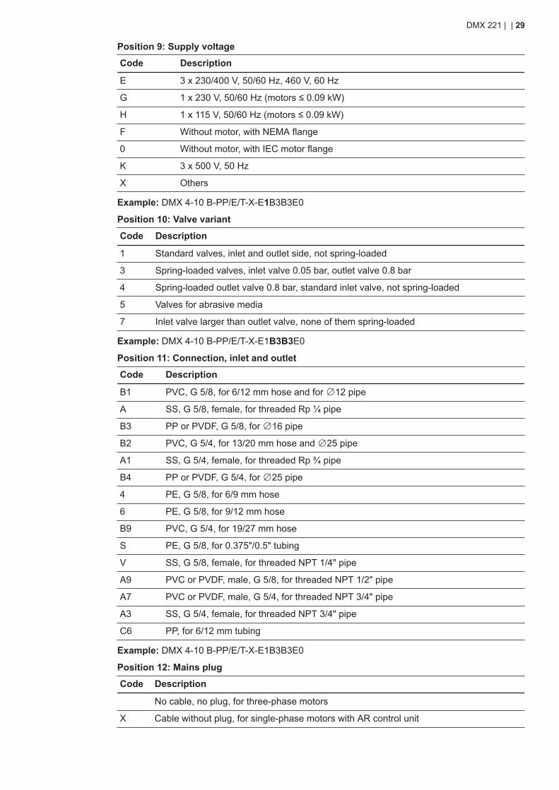
Position 9: Supply voltage
Code Description
E 3 x 230/400 V, 50/60 Hz, 460 V, 60 Hz
G 1 x 230 V, 50/60 Hz (motors ≤ 0.09 kW)
H 1 x 115 V, 50/60 Hz (motors ≤ 0.09 kW)
F Without motor, with NEMA flange
0 Without motor, with IEC motor flange
K 3 x 500 V, 50 Hz
X Others
Example: DMX 4-10 B-PP/E/T-X-E1B3B3E0
Position 10: Valve variant
Code Description
1 Standard valves, inlet and outlet side, not spring-loaded
3 Spring-loaded valves, inlet valve 0.05 bar, outlet valve 0.8 bar
4 Spring-loaded outlet valve 0.8 bar, standard inlet valve, not spring-loaded
5 Valves for abrasive media
7 Inlet valve larger than outlet valve, none of them spring-loaded
Example: DMX 4-10 B-PP/E/T-X-E1B3B3E0
Position 11: Connection, inlet and outlet
Code Description
B1 PVC, G 5/8, for 6/12 mm hose and for ∅12 pipe
A SS, G 5/8, female, for threaded Rp ¼ pipe
B3 PP or PVDF, G 5/8, for ∅16 pipe
B2 PVC, G 5/4, for 13/20 mm hose and ∅25 pipe
A1 SS, G 5/4, female, for threaded Rp ¾ pipe
B4 PP or PVDF, G 5/4, for ∅25 pipe
4 PE, G 5/8, for 6/9 mm hose
6 PE, G 5/8, for 9/12 mm hose
B9 PVC, G 5/4, for 19/27 mm hose
S PE, G 5/8, for 0.375"/0.5" tubing
V SS, G 5/8, female, for threaded NPT 1/4" pipe
A9 PVC or PVDF, male, G 5/8, for threaded NPT 1/2" pipe
A7 PVC or PVDF, male, G 5/4, for threaded NPT 3/4" pipe
A3 SS, G 5/4, female, for threaded NPT 3/4" pipe
C6 PP, for 6/12 mm tubing
Example: DMX 4-10 B-PP/E/T-X-E1B3B3E0
Position 12: Mains plug
Code Description
No cable, no plug, for three-phase motors
X Cable without plug, for single-phase motors with AR control unit
DMX 221 | | 29
Code Description
F Safety plug type F (Schuko), for single-phase motors with AR control unit
B Plug for the USA and Canada, for single-phase motors with AR control unit
E Plug for Switzerland, for single-phase motors with AR control unit
Example: DMX 4-10 B-PP/E/T-X-E1B3B3E0
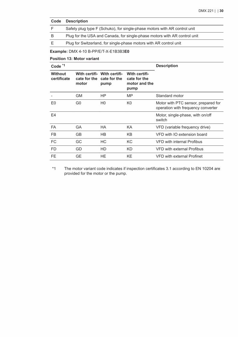
Position 13: Motor variant
Code *1 Description
Withoutcertificate
With certifi-cate for themotor
With certifi-cate for thepump
With certifi-cate for themotor and thepump
- GM HP MP Standard motor
E0 G0 H0 K0 Motor with PTC sensor, prepared foroperation with frequency converter
E4 Motor, single-phase, with on/offswitch
FA GA HA KA VFD (variable frequency drive)
FB GB HB KB VFD with IO extension board
FC GC HC KC VFD with internal Profibus
FD GD HD KD VFD with external Profibus
FE GE HE KE VFD with external Profinet
*1 The motor variant code indicates if inspection certificates 3.1 according to EN 10204 areprovided for the motor or the pump.
DMX 221 | | 30
6. Taking the product out of operation
WARNINGChemical hazardDeath or serious personal injury● Observe the material safety data sheet of the dosing medium.● Wear protective clothing when working on the dosing head, connections or
lines.● Before relieving the pressure from the outlet side, make sure escaping dosing
medium cannot cause any harm to persons or equipment.● Collect and dispose of all chemicals in a way that is not harmful to persons or
the environment.
DANGERElectric shockDeath or serious personal injury● Electrical disconnection must be carried out by qualified persons.● Do not open the pump housing.● Switch off the power supply before making any electrical connections.
Close the vent plug when taking the pump out of operation for transport, storageor service.
1. Flush the dosing head with water, if possible.2. Stop dosing:
• For pumps with AR control unit, press the start/stop button on the AR control unit andswitch off the power supply to the pump.
• For pumps without AR control unit, switch off the power supply to the pump.3. Close the vent plug.4. Depressurise the pressure side of the dosing system.5. Close the isolating valves on the inlet side and outlet side, if installed.6. Make sure no dosing medium can flow back from the outlet side.7. Make sure the returning dosing medium is safely collected.8. Disconnect the inlet line and the outlet line.9. Disconnect the pump electrically.
• For pumps with a mains plug, remove the mains plug from the power socket.• For pumps without mains plug, proceed as follows:
a. Open the terminal box on the motor.b. Disconnect the motor.c. Close the terminal box on the motor.
The pump is now ready for storage or transport.
DMX 221 | Taking the product out of operation | 31
7. Maintaining the product
7.1 Maintenance schedule
Maintenance interval Task
Monthly Check that dosing medium is not leaking out ofthe pump.
Monthly Clean the product with a soft cloth and pay spe-cial attention to the fan cover.
With a counterpressure up to 10 bar• every 12 months• every 4000 operating hours• in case of fault.
Clean or replace the dosing diaphragm, inletvalve and outlet valve.
With a counterpressure of 10 to 16 bar• every 6 months• every 2000 operating hours• in case of fault.
Clean or replace the dosing diaphragm, inletvalve and outlet valve.
• every 12 months• every 8000 operating hours• in case of fault.
Clean or replace the diaphragm of the integral re-lief valve.
In case of fault Check the diaphragm leakage sensor.
Every 5 years or every 20000 operatinghours
Have the gear grease changed.
Only qualified persons authorised byGrundfos are allowed to change thegear grease. Send the pump toGrundfos or an authorised service work-shop.
Related information• 7.3 Preparing for maintenance of the dosing diaphragm or the valves• 7.4 Cleaning or replacing the inlet and outlet valves• 7.5 Cleaning or replacing the dosing diaphragm• 7.6 Cleaning or replacing the diaphragm of the integral relief valve• 11.1.5 Maintaining the diaphragm leakage sensor• 7.7 Returning the product
DMX 221 | | 32
7.2 Safety instructions for maintaining the dosing diaphragm or the valvesWARNINGChemical hazardDeath or serious personal injury● Observe the material safety data sheet of the dosing medium.● Wear protective clothing when working on the dosing head, connections or
lines.● Before relieving the pressure from the outlet side, make sure escaping dosing
medium cannot cause any harm to persons or equipment.● Collect and dispose of all chemicals in a way that is not harmful to persons or
the environment.
DANGERElectric shockDeath or serious personal injury● Only qualified persons are allowed to service the pump.● Do not open the pump housing.
Related information• 7.3 Preparing for maintenance of the dosing diaphragm or the valves
7.3 Preparing for maintenance of the dosing diaphragm or the valves
Only adjust the stroke length while the pump is running.
Close the vent plug when taking the pump out of operation for transport, storageor service.
1. Flush the dosing head with water, if possible.2. While the pump is running, set the stroke-length adjusting knob to 100 %.3. Switch off the pump and disconnect it from the power supply.4. Close the vent plug.5. Depressurise the pressure side of the dosing system.6. Make sure no dosing medium can flow back from the outlet side.7. Make sure the returning dosing medium is safely collected.
The pump is now ready for maintenance.
Related information• 7.2 Safety instructions for maintaining the dosing diaphragm or the valves
DMX 221 | | 33
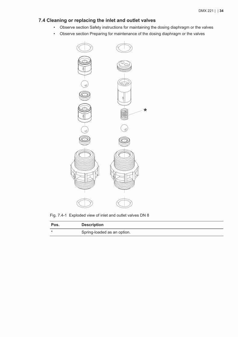
7.4 Cleaning or replacing the inlet and outlet valves• Observe section Safety instructions for maintaining the dosing diaphragm or the valves• Observe section Preparing for maintenance of the dosing diaphragm or the valves
*
Fig. 7.4-1 Exploded view of inlet and outlet valves DN 8
Pos. Description
* Spring-loaded as an option.
DMX 221 | | 34
* *1) 1)
*2)
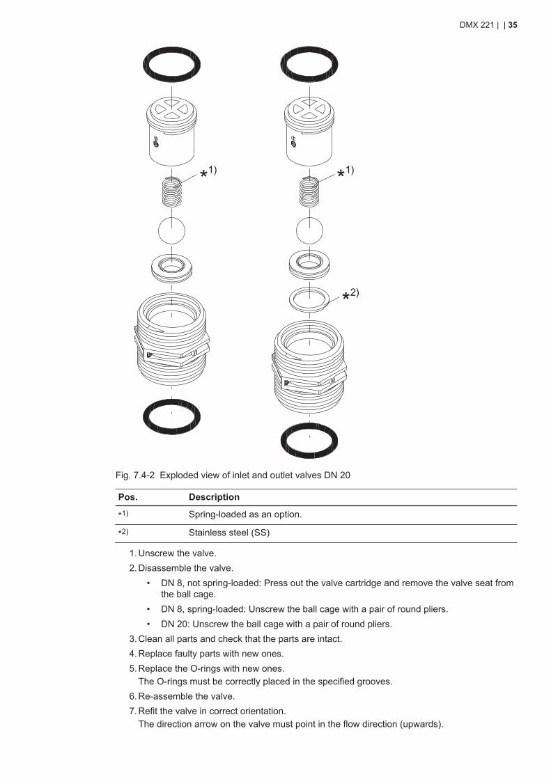
Fig. 7.4-2 Exploded view of inlet and outlet valves DN 20
Pos. Description
*1) Spring-loaded as an option.
*2) Stainless steel (SS)
1. Unscrew the valve.2. Disassemble the valve.
• DN 8, not spring-loaded: Press out the valve cartridge and remove the valve seat fromthe ball cage.
• DN 8, spring-loaded: Unscrew the ball cage with a pair of round pliers.• DN 20: Unscrew the ball cage with a pair of round pliers.
3. Clean all parts and check that the parts are intact.4. Replace faulty parts with new ones.5. Replace the O-rings with new ones.
The O-rings must be correctly placed in the specified grooves.6. Re-assemble the valve.7. Refit the valve in correct orientation.
The direction arrow on the valve must point in the flow direction (upwards).
DMX 221 | | 35
Related information• 7.3 Preparing for maintenance of the dosing diaphragm or the valves• 7.2 Safety instructions for maintaining the dosing diaphragm or the valves
7.5 Cleaning or replacing the dosing diaphragm• Observe section Safety instructions for maintaining the dosing diaphragm or the valves• Observe section Preparing for maintenance of the dosing diaphragm or the valves
1. Unscrew the dosing head screws.2. Remove the dosing head.3. Turn the motor fan blades until the diaphragm reaches the front dead centre.
The diaphragm will detach itself from the diaphragm flange.4. Turn the diaphragm counter-clockwise to unscrew the diaphragm from the tappet.5. Clean all parts and check that the parts are intact.6. Replace faulty parts with new ones.7. Screw in the diaphragm completely. Then turn it back until the holes in the diaphragm and
the flange are aligned.8. Turn the motor fan blades until the diaphragm reaches the back dead centre.
The diaphragm is moved towards the diaphragm flange.9. Refit the dosing head.
10. Cross-tighten the dosing head screws with the correct torque.11. After 6-10 operating hours or two days, retighten the screws with the correct torque.
Related information• 7.2 Safety instructions for maintaining the dosing diaphragm or the valves• 7.3 Preparing for maintenance of the dosing diaphragm or the valves• 9.3.1 Torque values
7.6 Cleaning or replacing the diaphragm of the integral relief valve• Observe section Safety instructions for maintaining the dosing diaphragm or the valves• Observe section Preparing for maintenance of the dosing diaphragm or the valves• Make sure a return flow or overpressure cannot occur.
1. Unscrew the four screws of the integral relief valve.2. Remove the top part of the integral relief valve.3. Remove the diaphragm.4. Clean all parts and check that the parts are intact.5. Replace faulty parts with new ones.6. Insert the diaphragm.7. Refit the top part of the integral relief valve.8. Cross-tighten the screws with the correct torque.9. After approximately 48 operating hours, retighten the screws with the correct torque.
Related information• 7.2 Safety instructions for maintaining the dosing diaphragm or the valves• 7.3 Preparing for maintenance of the dosing diaphragm or the valves• 9.3.1 Torque values
DMX 221 | | 36
7.7 Returning the productThere are two situations when a pump must be sent to Grundfos or an authorised service work-shop:
• every five years for gear grease exchange• whenever you request service on the pump.
WARNINGChemical hazardDeath or serious personal injury● Observe the material safety data sheet of the dosing medium.● Wear protective clothing when working on the dosing head, connections or
lines.● Collect and dispose of all chemicals in a way that is not harmful to persons or
the environment.
Grundfos can refuse to accept the product for service, if it is not cleaned from chemicals or if the"Safety declaration" is not provided.
1. Clean the pump thoroughly before returning it. Make sure there are no traces of toxic or haz-ardous chemicals remaining on the pump.If proper cleaning is not possible, provide all relevant information about the chemical.
2. Fill out the "Safety declaration" and attach it to the pump in a visible position.You can find the "Safety declaration" at the end of this document.
3. Make sure the product is suitably protected during transport.
Related information• 6. Taking the product out of operation• 4.1 Handling the product
DMX 221 | | 37
8. Fault finding the product
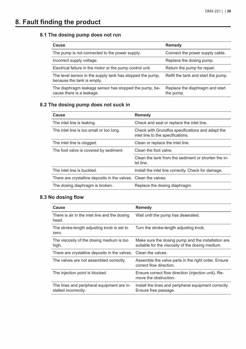
8.1 The dosing pump does not run
Cause Remedy
The pump is not connected to the power supply. Connect the power supply cable.
Incorrect supply voltage. Replace the dosing pump.
Electrical failure in the motor or the pump control unit. Return the pump for repair.
The level sensor in the supply tank has stopped the pump,because the tank is empty.
Refill the tank and start the pump.
The diaphragm leakage sensor has stopped the pump, be-cause there is a leakage.
Replace the diaphragm and startthe pump.
8.2 The dosing pump does not suck in
Cause Remedy
The inlet line is leaking. Check and seal or replace the inlet line.
The inlet line is too small or too long. Check with Grundfos specifications and adapt theinlet line to the specifications.
The inlet line is clogged. Clean or replace the inlet line.
The foot valve is covered by sediment. Clean the foot valve.
Clean the tank from the sediment or shorten the in-let line.
The inlet line is buckled. Install the inlet line correctly. Check for damage.
There are crystalline deposits in the valves. Clean the valves.
The dosing diaphragm is broken. Replace the dosing diaphragm.
8.3 No dosing flow
Cause Remedy
There is air in the inlet line and the dosinghead.
Wait until the pump has deaerated.
The stroke-length adjusting knob is set tozero.
Turn the stroke-length adjusting knob.
The viscosity of the dosing medium is toohigh.
Make sure the dosing pump and the installation aresuitable for the viscosity of the dosing medium.
There are crystalline deposits in the valves. Clean the valves.
The valves are not assembled correctly. Assemble the valve parts in the right order. Ensurecorrect flow direction.
The injection point is blocked. Ensure correct flow direction (injection unit). Re-move the obstruction.
The lines and peripheral equipment are in-stalled incorrectly.
Install the lines and peripheral equipment correctly.Ensure free passage.
DMX 221 | | 38
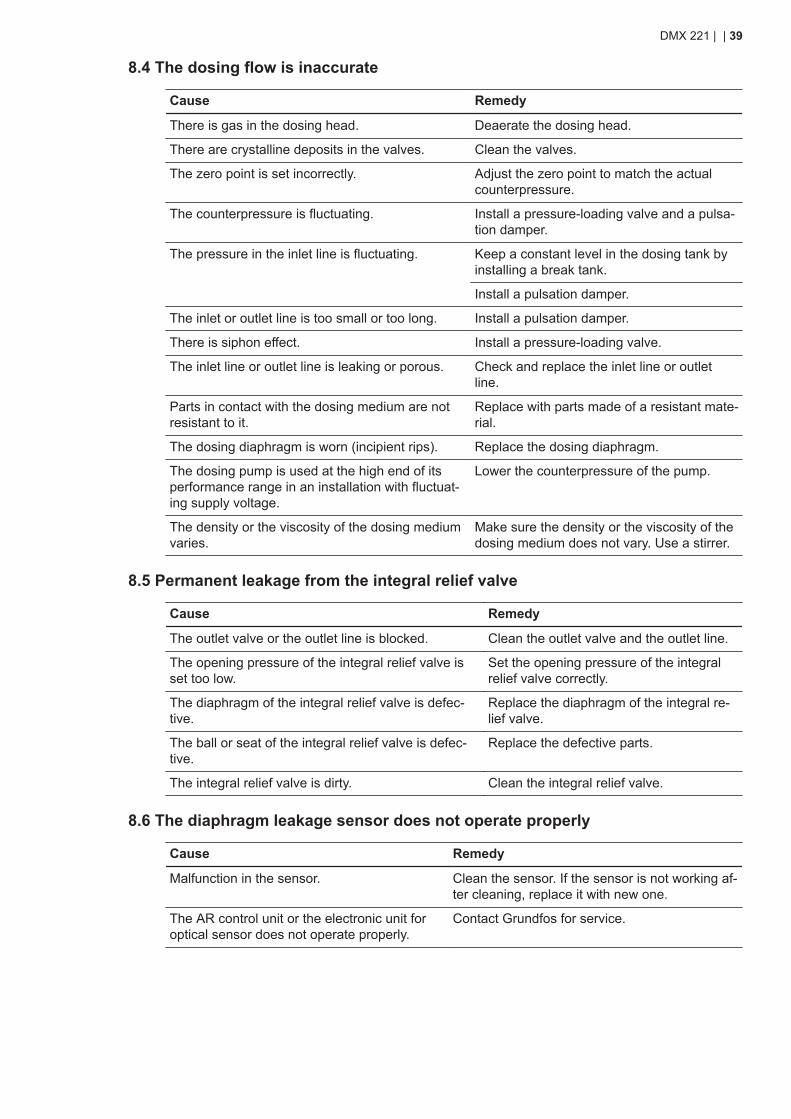
8.4 The dosing flow is inaccurate
Cause Remedy
There is gas in the dosing head. Deaerate the dosing head.
There are crystalline deposits in the valves. Clean the valves.
The zero point is set incorrectly. Adjust the zero point to match the actualcounterpressure.
The counterpressure is fluctuating. Install a pressure-loading valve and a pulsa-tion damper.
The pressure in the inlet line is fluctuating. Keep a constant level in the dosing tank byinstalling a break tank.
Install a pulsation damper.
The inlet or outlet line is too small or too long. Install a pulsation damper.
There is siphon effect. Install a pressure-loading valve.
The inlet line or outlet line is leaking or porous. Check and replace the inlet line or outletline.
Parts in contact with the dosing medium are notresistant to it.
Replace with parts made of a resistant mate-rial.
The dosing diaphragm is worn (incipient rips). Replace the dosing diaphragm.
The dosing pump is used at the high end of itsperformance range in an installation with fluctuat-ing supply voltage.
Lower the counterpressure of the pump.
The density or the viscosity of the dosing mediumvaries.
Make sure the density or the viscosity of thedosing medium does not vary. Use a stirrer.
8.5 Permanent leakage from the integral relief valve
Cause Remedy
The outlet valve or the outlet line is blocked. Clean the outlet valve and the outlet line.
The opening pressure of the integral relief valve isset too low.
Set the opening pressure of the integralrelief valve correctly.
The diaphragm of the integral relief valve is defec-tive.
Replace the diaphragm of the integral re-lief valve.
The ball or seat of the integral relief valve is defec-tive.
Replace the defective parts.
The integral relief valve is dirty. Clean the integral relief valve.
8.6 The diaphragm leakage sensor does not operate properly
Cause Remedy
Malfunction in the sensor. Clean the sensor. If the sensor is not working af-ter cleaning, replace it with new one.
The AR control unit or the electronic unit foroptical sensor does not operate properly.
Contact Grundfos for service.
DMX 221 | | 39
9. Technical data
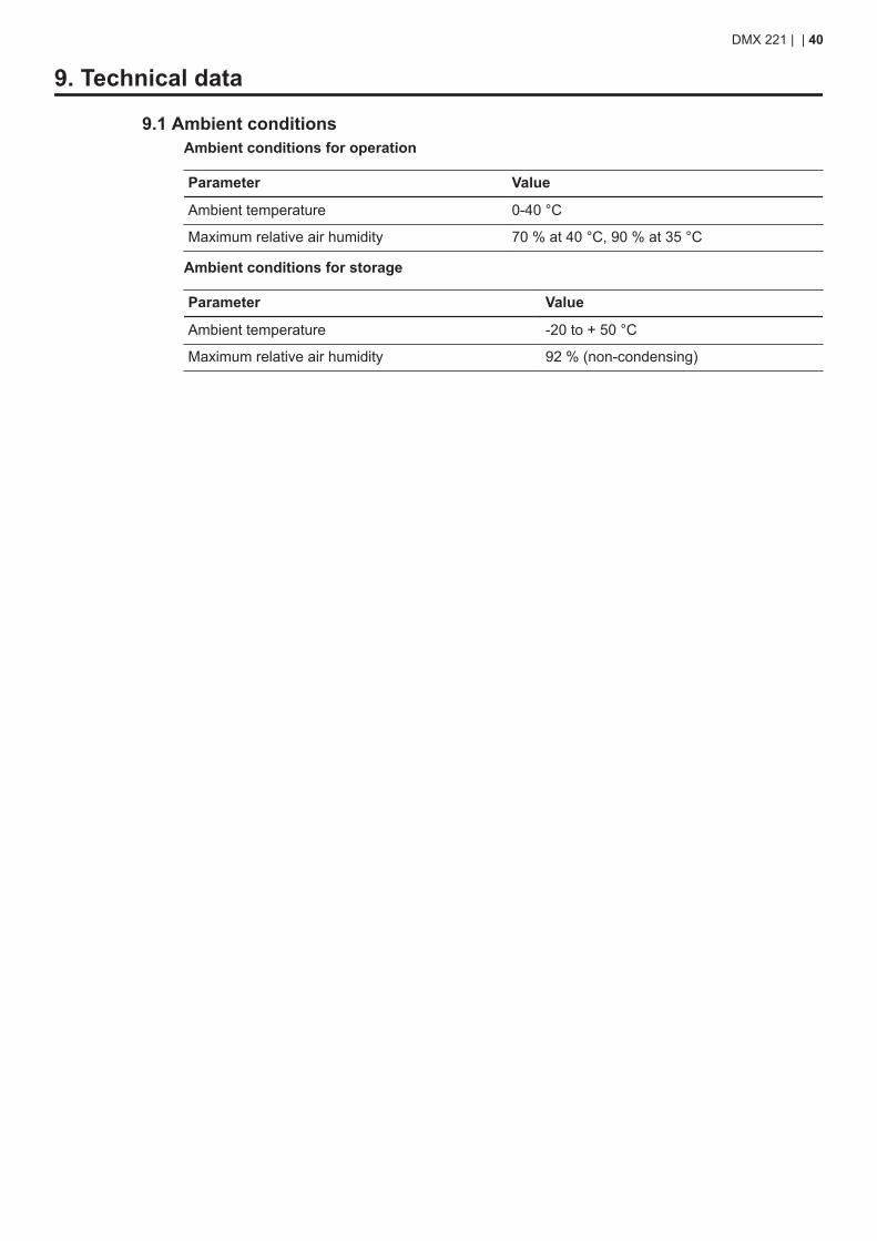
9.1 Ambient conditionsAmbient conditions for operation
Parameter Value
Ambient temperature 0-40 °C
Maximum relative air humidity 70 % at 40 °C, 90 % at 35 °C
Ambient conditions for storage
Parameter Value
Ambient temperature -20 to + 50 °C
Maximum relative air humidity 92 % (non-condensing)
DMX 221 | | 40
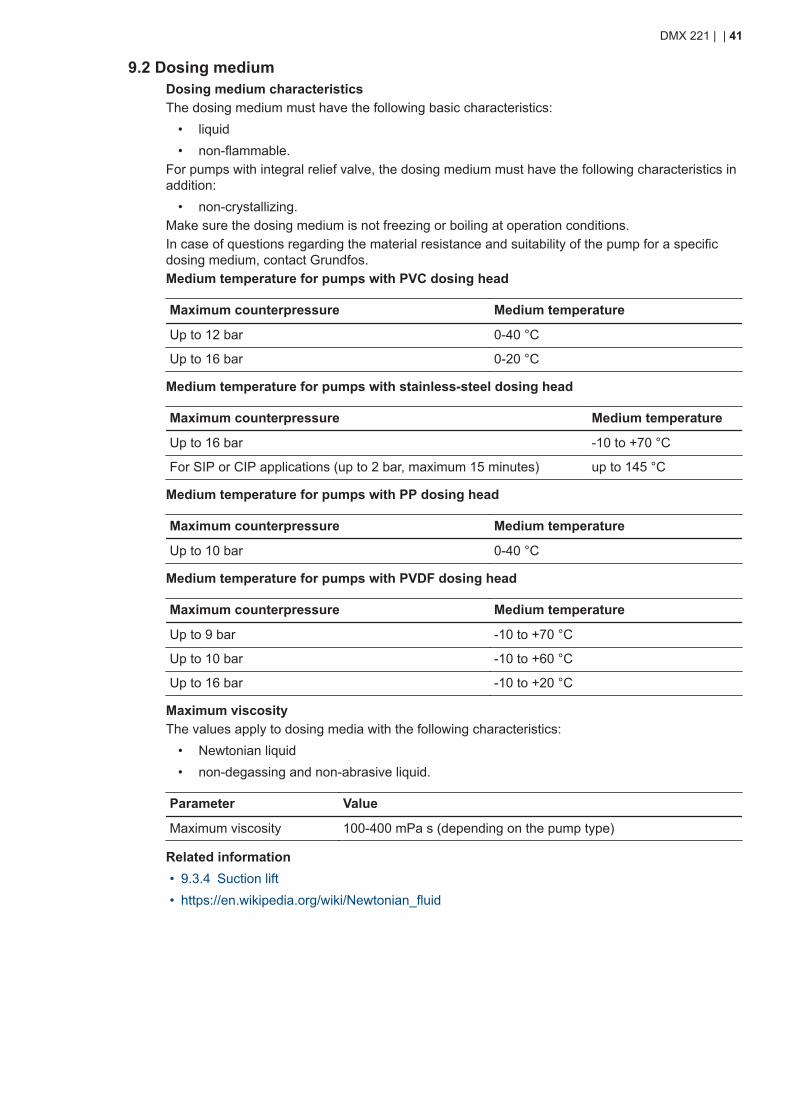
9.2 Dosing mediumDosing medium characteristicsThe dosing medium must have the following basic characteristics:
• liquid• non-flammable.
For pumps with integral relief valve, the dosing medium must have the following characteristics inaddition:
• non-crystallizing.Make sure the dosing medium is not freezing or boiling at operation conditions.In case of questions regarding the material resistance and suitability of the pump for a specificdosing medium, contact Grundfos.Medium temperature for pumps with PVC dosing head
Maximum counterpressure Medium temperature
Up to 12 bar 0-40 °C
Up to 16 bar 0-20 °C
Medium temperature for pumps with stainless-steel dosing head
Maximum counterpressure Medium temperature
Up to 16 bar -10 to +70 °C
For SIP or CIP applications (up to 2 bar, maximum 15 minutes) up to 145 °C
Medium temperature for pumps with PP dosing head
Maximum counterpressure Medium temperature
Up to 10 bar 0-40 °C
Medium temperature for pumps with PVDF dosing head
Maximum counterpressure Medium temperature
Up to 9 bar -10 to +70 °C
Up to 10 bar -10 to +60 °C
Up to 16 bar -10 to +20 °C
Maximum viscosityThe values apply to dosing media with the following characteristics:
• Newtonian liquid• non-degassing and non-abrasive liquid.
Parameter Value
Maximum viscosity 100-400 mPa s (depending on the pump type)
Related information• 9.3.4 Suction lift• https://en.wikipedia.org/wiki/Newtonian_fluid
DMX 221 | | 41
9.3 Mechanical data
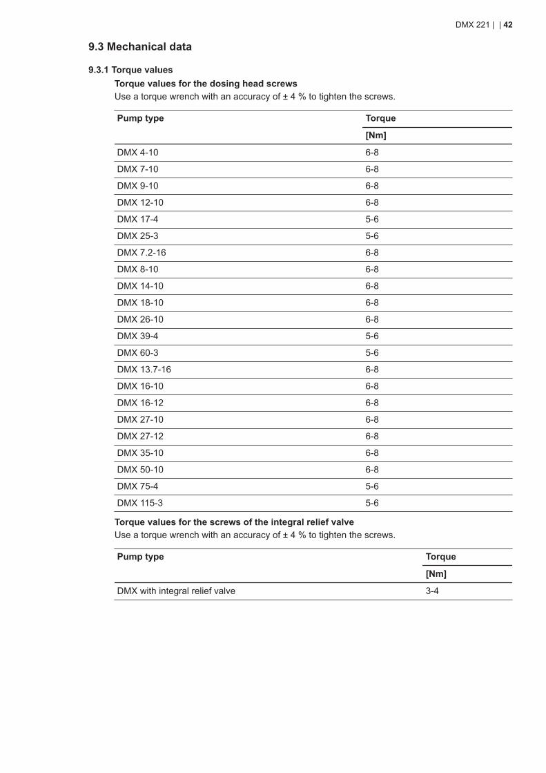
9.3.1 Torque valuesTorque values for the dosing head screwsUse a torque wrench with an accuracy of ± 4 % to tighten the screws.
Pump type Torque
[Nm]
DMX 4-10 6-8
DMX 7-10 6-8
DMX 9-10 6-8
DMX 12-10 6-8
DMX 17-4 5-6
DMX 25-3 5-6
DMX 7.2-16 6-8
DMX 8-10 6-8
DMX 14-10 6-8
DMX 18-10 6-8
DMX 26-10 6-8
DMX 39-4 5-6
DMX 60-3 5-6
DMX 13.7-16 6-8
DMX 16-10 6-8
DMX 16-12 6-8
DMX 27-10 6-8
DMX 27-12 6-8
DMX 35-10 6-8
DMX 50-10 6-8
DMX 75-4 5-6
DMX 115-3 5-6
Torque values for the screws of the integral relief valveUse a torque wrench with an accuracy of ± 4 % to tighten the screws.
Pump type Torque
[Nm]
DMX with integral relief valve 3-4
DMX 221 | | 42
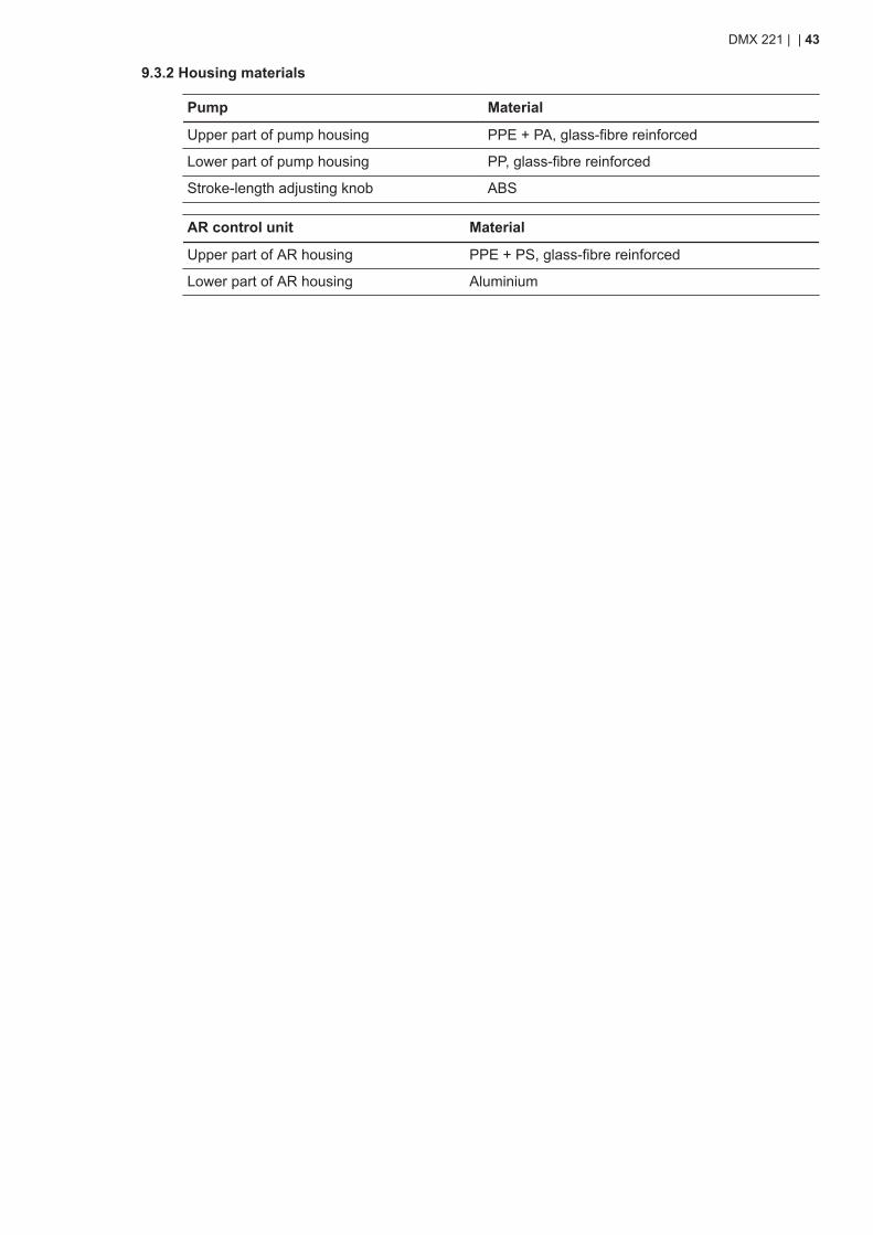
9.3.2 Housing materials
Pump Material
Upper part of pump housing PPE + PA, glass-fibre reinforced
Lower part of pump housing PP, glass-fibre reinforced
Stroke-length adjusting knob ABS
AR control unit Material
Upper part of AR housing PPE + PS, glass-fibre reinforced
Lower part of AR housing Aluminium
DMX 221 | | 43
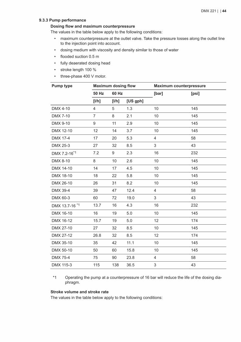
9.3.3 Pump performanceDosing flow and maximum counterpressureThe values in the table below apply to the following conditions:
• maximum counterpressure at the outlet valve. Take the pressure losses along the outlet lineto the injection point into account.
• dosing medium with viscosity and density similar to those of water• flooded suction 0.5 m• fully deaerated dosing head• stroke length 100 %• three-phase 400 V motor.
Pump type Maximum dosing flow Maximum counterpressure
50 Hz 60 Hz [bar] [psi]
[l/h] [l/h] [US gph]
DMX 4-10 4 5 1.3 10 145
DMX 7-10 7 8 2.1 10 145
DMX 9-10 9 11 2.9 10 145
DMX 12-10 12 14 3.7 10 145
DMX 17-4 17 20 5.3 4 58
DMX 25-3 27 32 8.5 3 43
DMX 7.2-16*1 7.2 9 2.3 16 232
DMX 8-10 8 10 2.6 10 145
DMX 14-10 14 17 4.5 10 145
DMX 18-10 18 22 5.8 10 145
DMX 26-10 26 31 8.2 10 145
DMX 39-4 39 47 12.4 4 58
DMX 60-3 60 72 19.0 3 43
DMX 13.7-16 *1 13.7 16 4.3 16 232
DMX 16-10 16 19 5.0 10 145
DMX 16-12 15.7 19 5.0 12 174
DMX 27-10 27 32 8.5 10 145
DMX 27-12 26.8 32 8.5 12 174
DMX 35-10 35 42 11.1 10 145
DMX 50-10 50 60 15.8 10 145
DMX 75-4 75 90 23.8 4 58
DMX 115-3 115 138 36.5 3 43
*1 Operating the pump at a counterpressure of 16 bar will reduce the life of the dosing dia-phragm.
Stroke volume and stroke rateThe values in the table below apply to the following conditions:
DMX 221 | | 44
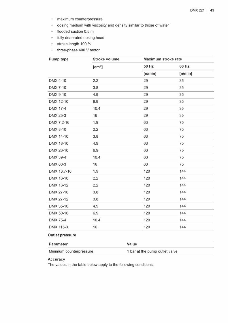
• maximum counterpressure• dosing medium with viscosity and density similar to those of water• flooded suction 0.5 m• fully deaerated dosing head• stroke length 100 %• three-phase 400 V motor.
Pump type Stroke volume Maximum stroke rate
[cm3] 50 Hz 60 Hz
[n/min] [n/min]
DMX 4-10 2.2 29 35
DMX 7-10 3.8 29 35
DMX 9-10 4.9 29 35
DMX 12-10 6.9 29 35
DMX 17-4 10.4 29 35
DMX 25-3 16 29 35
DMX 7.2-16 1.9 63 75
DMX 8-10 2.2 63 75
DMX 14-10 3.8 63 75
DMX 18-10 4.9 63 75
DMX 26-10 6.9 63 75
DMX 39-4 10.4 63 75
DMX 60-3 16 63 75
DMX 13.7-16 1.9 120 144
DMX 16-10 2.2 120 144
DMX 16-12 2.2 120 144
DMX 27-10 3.8 120 144
DMX 27-12 3.8 120 144
DMX 35-10 4.9 120 144
DMX 50-10 6.9 120 144
DMX 75-4 10.4 120 144
DMX 115-3 16 120 144
Outlet pressure
Parameter Value
Minimum counterpressure 1 bar at the pump outlet valve
AccuracyThe values in the table below apply to the following conditions:
DMX 221 | | 45

• dosing medium with viscosity and density similar to those of water• fully deaerated dosing head• standard pump version.
Parameter Value
Dosing flow fluctuation ± 1.5 % within the control range 1:10
Linearity deviation ± 4 % of the full-scale value. Adjustment from maximum to minimumstroke length within the control range 1:5.
DMX 221 | | 46
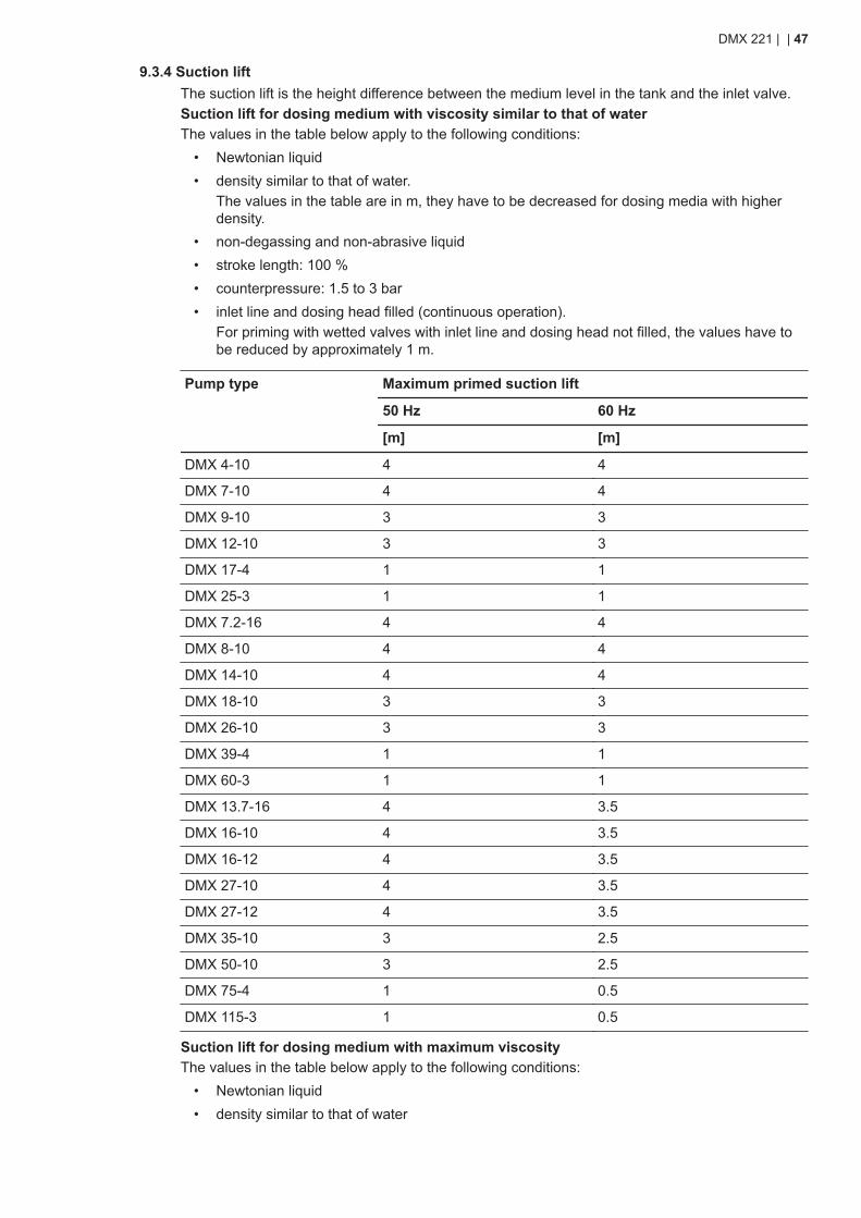
9.3.4 Suction liftThe suction lift is the height difference between the medium level in the tank and the inlet valve.Suction lift for dosing medium with viscosity similar to that of waterThe values in the table below apply to the following conditions:
• Newtonian liquid• density similar to that of water.
The values in the table are in m, they have to be decreased for dosing media with higherdensity.
• non-degassing and non-abrasive liquid• stroke length: 100 %• counterpressure: 1.5 to 3 bar• inlet line and dosing head filled (continuous operation).
For priming with wetted valves with inlet line and dosing head not filled, the values have tobe reduced by approximately 1 m.
Pump type Maximum primed suction lift
50 Hz 60 Hz
[m] [m]
DMX 4-10 4 4
DMX 7-10 4 4
DMX 9-10 3 3
DMX 12-10 3 3
DMX 17-4 1 1
DMX 25-3 1 1
DMX 7.2-16 4 4
DMX 8-10 4 4
DMX 14-10 4 4
DMX 18-10 3 3
DMX 26-10 3 3
DMX 39-4 1 1
DMX 60-3 1 1
DMX 13.7-16 4 3.5
DMX 16-10 4 3.5
DMX 16-12 4 3.5
DMX 27-10 4 3.5
DMX 27-12 4 3.5
DMX 35-10 3 2.5
DMX 50-10 3 2.5
DMX 75-4 1 0.5
DMX 115-3 1 0.5
Suction lift for dosing medium with maximum viscosityThe values in the table below apply to the following conditions:
• Newtonian liquid• density similar to that of water
DMX 221 | | 47
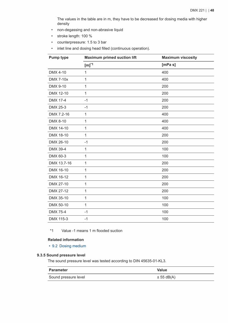
The values in the table are in m, they have to be decreased for dosing media with higherdensity
• non-degassing and non-abrasive liquid• stroke length: 100 %• counterpressure: 1.5 to 3 bar• inlet line and dosing head filled (continuous operation).
Pump type Maximum primed suction lift Maximum viscosity
[m]*1 [mPa s]
DMX 4-10 1 400
DMX 7-10x 1 400
DMX 9-10 1 200
DMX 12-10 1 200
DMX 17-4 -1 200
DMX 25-3 -1 200
DMX 7.2-16 1 400
DMX 8-10 1 400
DMX 14-10 1 400
DMX 18-10 1 200
DMX 26-10 -1 200
DMX 39-4 1 100
DMX 60-3 1 100
DMX 13.7-16 1 200
DMX 16-10 1 200
DMX 16-12 1 200
DMX 27-10 1 200
DMX 27-12 1 200
DMX 35-10 1 100
DMX 50-10 1 100
DMX 75-4 -1 100
DMX 115-3 -1 100
*1 Value -1 means 1 m flooded suction
Related information• 9.2 Dosing medium
9.3.5 Sound pressure levelThe sound pressure level was tested according to DIN 45635-01-KL3.
Parameter Value
Sound pressure level ± 55 dB(A)
DMX 221 | | 48
9.4 Electrical dataEnclosure class
• The enclosure class depends on the motor variant selected and is stated on the motornameplate.
• The specified enclosure class can only be ensured if the power supply cable is connectedwith the same degree of protection.
• For pumps with electronics, the specified enclosure class applies to pumps with correctly in-serted plugs or screwed-on caps. The specified enclosure class can only be ensured if thesockets are protected.
Motor dataThe motor data depends on the motor variant selected and is stated on the motor and pumpnameplate.Electrical data of pump electronicsFor pumps equipped with an AR control unit, VFD or Servomotor, separate installation and oper-ating instructions including the electrical data of the electronics are supplied with the pump.
Related information• 11.1.6 Technical data of the electronic unit for optical sensor• 11.2.5 Technical data of DMX pumps with VFD
DMX 221 | | 49
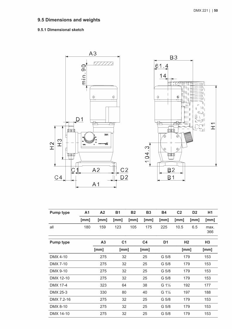
9.5 Dimensions and weights
9.5.1 Dimensional sketch
Pump type A1 A2 B1 B2 B3 B4 C2 D2 H1
[mm] [mm] [mm] [mm] [mm] [mm] [mm] [mm] [mm]
all 180 159 123 105 175 225 10.5 6.5 max.366
Pump type A3 C1 C4 D1 H2 H3
[mm] [mm] [mm] [mm] [mm]
DMX 4-10 275 32 25 G 5/8 179 153
DMX 7-10 275 32 25 G 5/8 179 153
DMX 9-10 275 32 25 G 5/8 179 153
DMX 12-10 275 32 25 G 5/8 179 153
DMX 17-4 323 64 38 G 1¼ 192 177
DMX 25-3 330 80 40 G 1¼ 197 188
DMX 7.2-16 275 32 25 G 5/8 179 153
DMX 8-10 275 32 25 G 5/8 179 153
DMX 14-10 275 32 25 G 5/8 179 153
DMX 221 | | 50
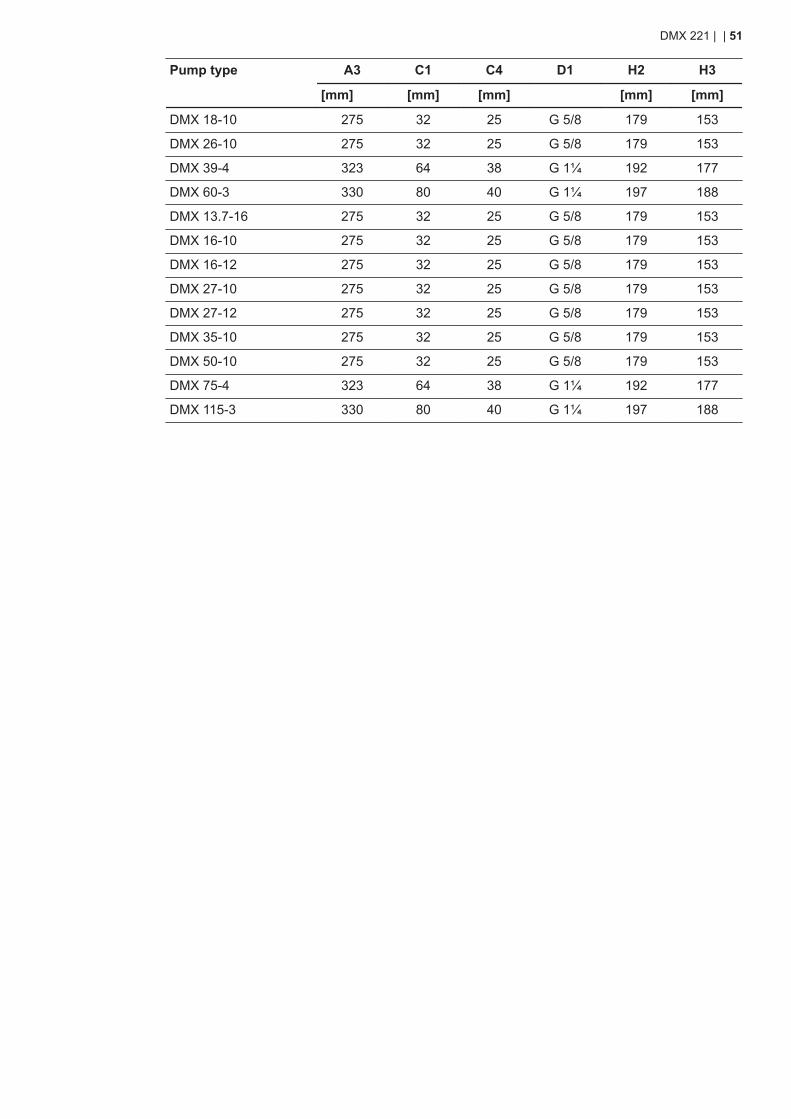
Pump type A3 C1 C4 D1 H2 H3
[mm] [mm] [mm] [mm] [mm]
DMX 18-10 275 32 25 G 5/8 179 153
DMX 26-10 275 32 25 G 5/8 179 153
DMX 39-4 323 64 38 G 1¼ 192 177
DMX 60-3 330 80 40 G 1¼ 197 188
DMX 13.7-16 275 32 25 G 5/8 179 153
DMX 16-10 275 32 25 G 5/8 179 153
DMX 16-12 275 32 25 G 5/8 179 153
DMX 27-10 275 32 25 G 5/8 179 153
DMX 27-12 275 32 25 G 5/8 179 153
DMX 35-10 275 32 25 G 5/8 179 153
DMX 50-10 275 32 25 G 5/8 179 153
DMX 75-4 323 64 38 G 1¼ 192 177
DMX 115-3 330 80 40 G 1¼ 197 188
DMX 221 | | 51
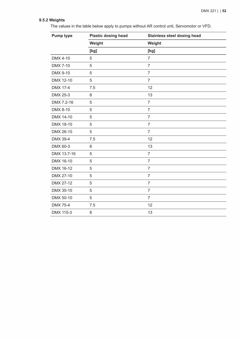
9.5.2 WeightsThe values in the table below apply to pumps without AR control unit, Servomotor or VFD.
Pump type Plastic dosing head Stainless steel dosing head
Weight Weight
[kg] [kg]
DMX 4-10 5 7
DMX 7-10 5 7
DMX 9-10 5 7
DMX 12-10 5 7
DMX 17-4 7.5 12
DMX 25-3 8 13
DMX 7.2-16 5 7
DMX 8-10 5 7
DMX 14-10 5 7
DMX 18-10 5 7
DMX 26-10 5 7
DMX 39-4 7.5 12
DMX 60-3 8 13
DMX 13.7-16 5 7
DMX 16-10 5 7
DMX 16-12 5 7
DMX 27-10 5 7
DMX 27-12 5 7
DMX 35-10 5 7
DMX 50-10 5 7
DMX 75-4 7.5 12
DMX 115-3 8 13
DMX 221 | | 52
9.6 Dosing curvesThe dosing curves are approximated curves showing the dependency between pump perform-ance, counterpressure and stroke length. The stated values apply to the following conditions:
• Newtonian liquid• density similar to that of water• inlet line with foot valve• flooded suction, 0.5 m• zero point of pump for specified pressure• standard pump version.
Abbreviation Description
Q Dosing flow
Q0 Zero point of the pump.
Q [l/h] Dosing flow in litres per hour
h Stroke length
h [%] Stroke length in percent of maximum stroke length
Hz Frequency of the alternating current power supply in Hz = 1/s
bar Counterpressure at the pump outlet valve in bar
Related information• A.1. Curves
DMX 221 | | 53
10. Disposing of the product
10.1 Disposing of hazardous or toxic materialsWARNINGChemical hazardDeath or serious personal injury● Observe the material safety data sheet of the dosing medium.● Wear protective clothing when working on the dosing head, connections or
lines.● Rinse the parts that have been in contact with the dosing medium.● Collect and dispose of all chemicals in a way that is not harmful to persons or
the environment.
The materials used in DMX pumps do not pose any health risk to the person handling them. Toidentify the specific materials, check the type key on the product nameplate and read the explana-tion in the section Type key.Observe also the product recycling page on http://www.grundfos.com/products/product-sustaina-bility/dmx.html
Related information• 5.3.2 Type key
10.2 Disposing of the productThis product or parts of it must be disposed of in an environmentally sound way.
1. Use the public or private waste collection service.2. If this is not possible, contact the nearest Grundfos company or service workshop.
Related information• 6. Taking the product out of operation
DMX 221 | | 54
11. Pump options and variants
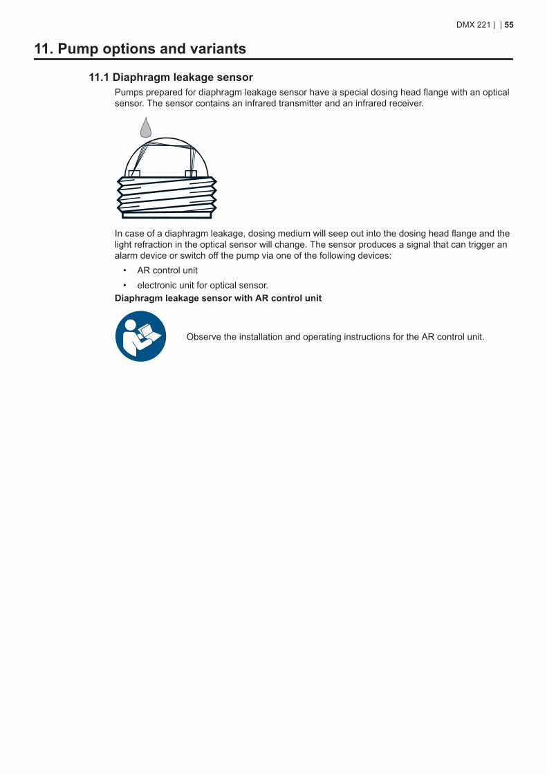
11.1 Diaphragm leakage sensorPumps prepared for diaphragm leakage sensor have a special dosing head flange with an opticalsensor. The sensor contains an infrared transmitter and an infrared receiver.
In case of a diaphragm leakage, dosing medium will seep out into the dosing head flange and thelight refraction in the optical sensor will change. The sensor produces a signal that can trigger analarm device or switch off the pump via one of the following devices:
• AR control unit• electronic unit for optical sensor.
Diaphragm leakage sensor with AR control unit
Observe the installation and operating instructions for the AR control unit.
DMX 221 | | 55
11.1.1 Function of the electronic unit for optical sensorRelay outputsThe electronic unit for optical sensor has two relay outputs:
• Relay 1 (C1): potential-loaded output, AC mains voltage, 230 V or 115 V, depending on themodelC1 can be used to switch off the pump in case of a diaphragm leakage.
• Relay 2 (C2): potential-free outputC2 can be used to trigger an alarm device in case of diaphragm leakage.
LEDsThe electronic unit for optical sensor has two LEDs.
• Green LED:• The green LED indicates that the system is ready for operation.• The green LED is on when the sensor is connected to the electronic unit. If the LED is
off, the sensor is defective or wrongly connected.• The green LED stays on when the red LED is on.
• Red LED:• The red LED indicates that a diaphragm leakage has been detected.
11.1.2 Mounting the electronic unit for optical sensorHave a screwdriver for the plastic screws in the cover of the electronic unit available. You alsoneed four 4.5 x 35 mm screws and a suitable screwdriver for fastening the unit to the wall. Thefour screws are not included in the scope of delivery.The diaphragm leakage sensor with electronic unit for optical sensor is supplied with a 5 m cable.Mount the electronic unit on the wall close to the pump.
1. Drill four Ø6 holes according to the drilling scheme.2. Unscrew the plastic screws in the cover of the electronic unit.3. Remove the cover with the plastic screws from the electronic unit.4. Mount the electronic unit on the wall by means of the four screws.5. Tighten the screws gently in order not to damage the electronic unit.6. Fit the cover to the electronic unit and fasten it with the plastic screws.
Related information• 11.1.6.1 Dimensional sketch of the electronic unit for optical sensor
11.1.3 Electrical connection
DANGERElectric shockDeath or serious personal injury● All electrical connections must be carried out by qualified persons.● Switch off the power supply before making any electrical connections.
• Make sure the power supply specified on the nameplate matches the local conditions.• Provide relay outputs on site with appropriate backup fuses.• To ensure electromagnetic compatibility (EMC), the input cables and current output cables
must be screened.• Route input cables, current output cables and power supply cables in separate ducts.
11.1.3.1 Connecting the diaphragm leakage sensor electrically with the AR control unitIf the pump is equipped with an AR control unit, the diaphragm leakage sensor has a 1 m cablewith an M12 plug.
Observe the installation and operating instructions for the AR control unit.
DMX 221 | | 56
Insert the plug of the diaphragm leakage sensor into socket 1 of the AR control unit.
Related information• 11.1.3 Electrical connection
11.1.3.2 Connecting the diaphragm leakage sensor electrically with the electronic unit for opticalsensor
Observe section Electrical connection.If the diaphragm leakage sensor is used with an electronic unit for optical sensor, the diaphragmleakage sensor has a 3 m cable.Connecting the diaphragm leakage sensor to the electronic unit:
1. Unscrew the plastic screws in the cover of the electronic unit.2. Remove the cover with the plastic screws from the electronic unit.3. Lead the sensor cable through cable gland on the right side of the electronic unit.4. Connect the cable screen at one end to PE.5. Connect the cable wires to the sensor connection T2 as listed below, and tighten the screws.
a. Connect the green wire to GN.b. Connect the yellow wire to YE.c. Connect the white wire to WH.
See the wiring diagram below.6. Tighten the cable gland.
Connecting the relay outputs:7. Connect the contact outputs C1 and C2 according to the individual needs.
DANGERElectric shockDeath or serious personal injury
● Switch off the power supply before connecting contact 1.
The relay output connection depends on the application and the connected actuators.If required, mount an additional cable gland in the bottom of the electronic unit.
8. Lead the cables through the cable glands on the right side of the bottom of the electronicunit.
9. Connect the wires to contact output C1 and C2 and tighten the screws.See the wiring diagram below.
10. Tighten the cable gland.
Connecting the power supply:11. Lead the cable through the left cable gland in the bottom of the electronic unit.12. Connect the power supply to T1.
See the wiring diagram below.
DMX 221 | | 57
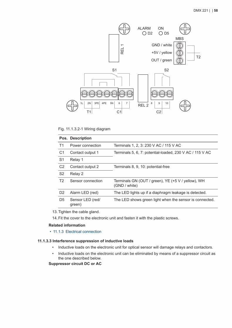
ALARM ON
MBS
GND / white
+5V / yellow
OUT / green
RE
L 1
REL 21L 2N 3PE 4PE 5N 6 7
D2 D5
8 9 10
S2S1
T1 C1
T2
C2
Fig. 11.1.3.2-1 Wiring diagram
Pos. Description
T1 Power connection Terminals 1, 2, 3: 230 V AC / 115 V AC
C1 Contact output 1 Terminals 5, 6, 7: potential-loaded, 230 V AC / 115 V AC
S1 Relay 1
C2 Contact output 2 Terminals 8, 9, 10: potential-free
S2 Relay 2
T2 Sensor connection Terminals GN (OUT / green), YE (+5 V / yellow), WH(GND / white)
D2 Alarm LED (red) The LED lights up if a diaphragm leakage is detected.
D5 Sensor LED (red/green)
The LED shows green light when the sensor is connected.
13. Tighten the cable gland.14. Fit the cover to the electronic unit and fasten it with the plastic screws.
Related information• 11.1.3 Electrical connection
11.1.3.3 Interference suppression of inductive loads• Inductive loads on the electronic unit for optical sensor will damage relays and contactors.• Inductive loads on the electronic unit can be eliminated by means of a suppressor circuit as
the one described below.Suppressor circuit DC or AC
DMX 221 | | 58
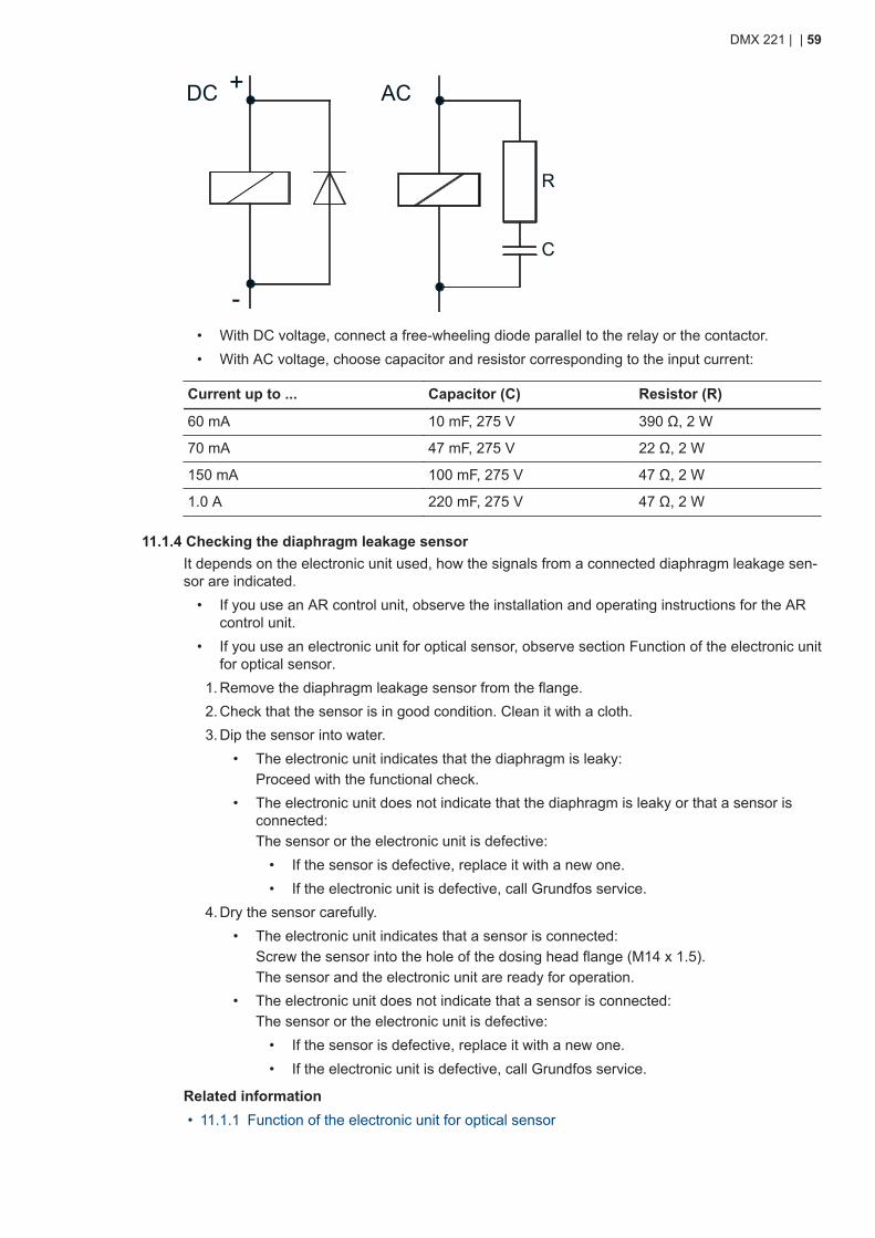
ACDC +
-
R
C
• With DC voltage, connect a free-wheeling diode parallel to the relay or the contactor.• With AC voltage, choose capacitor and resistor corresponding to the input current:
Current up to ... Capacitor (C) Resistor (R)
60 mA 10 mF, 275 V 390 Ω, 2 W
70 mA 47 mF, 275 V 22 Ω, 2 W
150 mA 100 mF, 275 V 47 Ω, 2 W
1.0 A 220 mF, 275 V 47 Ω, 2 W
11.1.4 Checking the diaphragm leakage sensorIt depends on the electronic unit used, how the signals from a connected diaphragm leakage sen-sor are indicated.
• If you use an AR control unit, observe the installation and operating instructions for the ARcontrol unit.
• If you use an electronic unit for optical sensor, observe section Function of the electronic unitfor optical sensor.
1. Remove the diaphragm leakage sensor from the flange.2. Check that the sensor is in good condition. Clean it with a cloth.3. Dip the sensor into water.
• The electronic unit indicates that the diaphragm is leaky:Proceed with the functional check.
• The electronic unit does not indicate that the diaphragm is leaky or that a sensor isconnected:The sensor or the electronic unit is defective:
• If the sensor is defective, replace it with a new one.• If the electronic unit is defective, call Grundfos service.
4. Dry the sensor carefully.• The electronic unit indicates that a sensor is connected:
Screw the sensor into the hole of the dosing head flange (M14 x 1.5).The sensor and the electronic unit are ready for operation.
• The electronic unit does not indicate that a sensor is connected:The sensor or the electronic unit is defective:
• If the sensor is defective, replace it with a new one.• If the electronic unit is defective, call Grundfos service.
Related information• 11.1.1 Function of the electronic unit for optical sensor
DMX 221 | | 59
11.1.5 Maintaining the diaphragm leakage sensor
DANGERElectric shockDeath or serious personal injury● Do not work on the electronic device of the diaphragm leakage sensor.
1. Check the diaphragm leakage sensor.2. If the sensor is defective, replace it with a new one.3. If the electronic unit is defective, call Grundfos service.
The electronic unit is maintenance-free.
Related information• 11.1.4 Checking the diaphragm leakage sensor
11.1.6 Technical data of the electronic unit for optical sensor
Parameter Value
Maximum mains voltage deviation ± 10 %
Contact load 250 V / 6 A, maximum 550 VA
Power consumption 1.15 VA
Enclosure class IP65
Permissible ambient temperature 0-40 °C
Models
Product number Mains voltage
96725701 230 V, AC
91835310 115 V, AC
11.1.6.1 Dimensional sketch of the electronic unit for optical sensorDimensions and drilling scheme for the electronic unit for optical sensor. All measurements in[mm].
DMX 221 | | 60
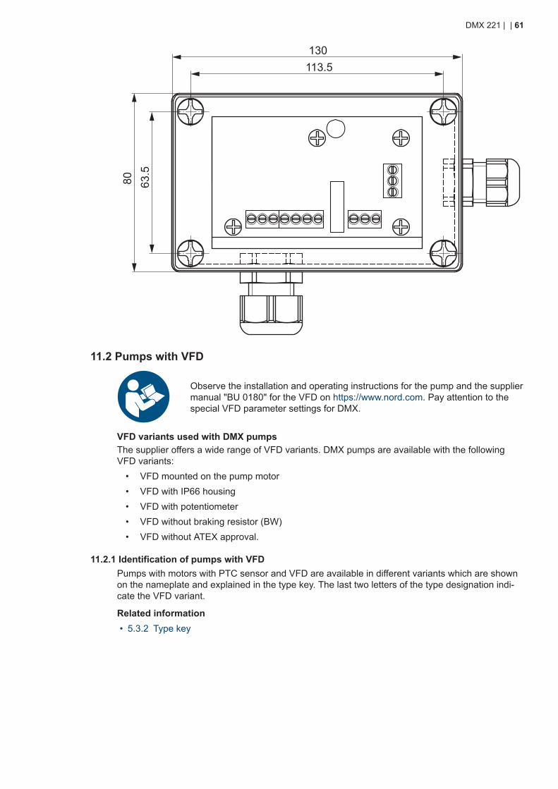
130113.5
63.5
80
11.2 Pumps with VFD
Observe the installation and operating instructions for the pump and the suppliermanual "BU 0180" for the VFD on https://www.nord.com. Pay attention to thespecial VFD parameter settings for DMX.
VFD variants used with DMX pumpsThe supplier offers a wide range of VFD variants. DMX pumps are available with the followingVFD variants:
• VFD mounted on the pump motor• VFD with IP66 housing• VFD with potentiometer• VFD without braking resistor (BW)• VFD without ATEX approval.
11.2.1 Identification of pumps with VFDPumps with motors with PTC sensor and VFD are available in different variants which are shownon the nameplate and explained in the type key. The last two letters of the type designation indi-cate the VFD variant.
Related information• 5.3.2 Type key
DMX 221 | | 61
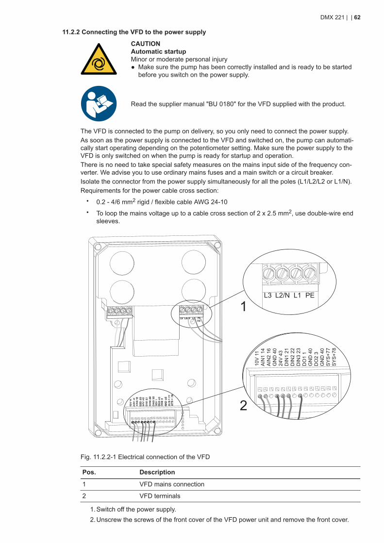
11.2.2 Connecting the VFD to the power supply
CAUTIONAutomatic startupMinor or moderate personal injury● Make sure the pump has been correctly installed and is ready to be started
before you switch on the power supply.
Read the supplier manual "BU 0180" for the VFD supplied with the product.
The VFD is connected to the pump on delivery, so you only need to connect the power supply.As soon as the power supply is connected to the VFD and switched on, the pump can automati-cally start operating depending on the potentiometer setting. Make sure the power supply to theVFD is only switched on when the pump is ready for startup and operation.There is no need to take special safety measures on the mains input side of the frequency con-verter. We advise you to use ordinary mains fuses and a main switch or a circuit breaker.Isolate the connector from the power supply simultaneously for all the poles (L1/L2/L2 or L1/N).Requirements for the power cable cross section:
• 0.2 - 4/6 mm2 rigid / flexible cable AWG 24-10• To loop the mains voltage up to a cable cross section of 2 x 2.5 mm2, use double-wire end
sleeves.
10V
11
AIN
1 14
AIN
2 16
GN
D 4
024
V 4
3D
IN1
21D
IN2
22D
IN3
23D
O1
1G
ND
40
DO
2 3
GN
D 4
0S
YS
+77
SY
S+7
8
L3 L2/N L1 PE
1
2
Fig. 11.2.2-1 Electrical connection of the VFD
Pos. Description
1 VFD mains connection
2 VFD terminals
1. Switch off the power supply.2. Unscrew the screws of the front cover of the VFD power unit and remove the front cover.
DMX 221 | | 62
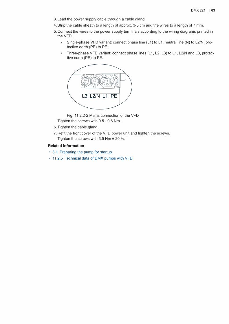
3. Lead the power supply cable through a cable gland.4. Strip the cable sheath to a length of approx. 3-5 cm and the wires to a length of 7 mm.5. Connect the wires to the power supply terminals according to the wiring diagrams printed in
the VFD.• Single-phase VFD variant: connect phase line (L1) to L1, neutral line (N) to L2/N, pro-
tective earth (PE) to PE.• Three-phase VFD variant: connect phase lines (L1, L2, L3) to L1, L2/N and L3, protec-
tive earth (PE) to PE.
L3 L2/N L1 PE
Fig. 11.2.2-2 Mains connection of the VFDTighten the screws with 0.5 - 0.6 Nm.
6. Tighten the cable gland.7. Refit the front cover of the VFD power unit and tighten the screws.
Tighten the screws with 3.5 Nm ± 20 %.
Related information• 3.1 Preparing the pump for startup• 11.2.5 Technical data of DMX pumps with VFD
DMX 221 | | 63

11.2.3 Operating modes
Read the supplier manual "BU 0180" for the VFD supplied with the product.
The selection of the operating mode (manual or analog) can be made via a central control unit.• If analog input 1 (AIN 1) is activated, manual mode is selected. The VFD is operated via the
potentiometer.• If analog input 2 (AIN 2) is activated, analog mode is selected. The VFD is operated via ana-
log signal 4-20 mA.Permanent setting of operating mode (VFD variant A)If there is no central control unit, the operating mode can be set permanently to manual or analog.The VFD is default set to manual operation via the potentiometer.Manual operation via the integrated potentiometer (default)
• Terminals 43 and 22 are connected with a jumper.• Digital input 2 is activated.• AIN 1, which is assigned to the potentiometer, is activated.
• Speed control is only possible via the potentiometer.For 4-20 mA analog operation, make the settings described below.Changing operating mode to analog operation (optional)
• Disconnect the jumper from terminal 22 and connect it to terminal 23.• Digital input 3 is activated.• AIN 2 is activated.
• Signal input is made via the terminals 40 (-) and 16 (+).
10 V
11
24 V
43
DIN
1 21
DIN
2 22
DIN
3 23
DO
1 1
DO
2 3
AIN
1 14
AIN
2 16
GN
D 4
0
GN
D 4
0
GN
D 4
0S
YS
+ 7
7S
YS
+ 7
8
Fig. 11.2.3-1 VFD terminalsOperating modes for other VFD variants (B - E)
DMX 221 | | 64
Read the supplier manual "BU 0180" for the VFD when setting the operatingmode for a VFD variants B-E.
11.2.4 Special VFD parameter settings for DMX• Some parameters have been adapted to DMX pumps. These parameters differ from the de-
fault settings mentioned in the supplier manual for the VFD.• Do not change the special parameter settings of the VFD for operation with DMX pumps.• When resetting the VFD to default settings, the special parameter settings for DMX will be
overwritten. The special parameters must be set again.Mandatory settings
• Do not set P506, "automatic fault acknowledgement", to 6, "always". In case of an active er-ror, such as leakage to earth or short circuit, the VFD will restart continuously and causedamage to the system because P428 is set to 1, "on".
• Do not change the following settings as this may lead to malfunction of the DMX pump withVFD.
Basic parameters
Code Parameter Value for DMX
P102 Startup time 5 s
P105 Maximum frequency 100 Hz
Control terminals
Code Index Parameter Value for DMX
P400 -02 Setpoint input function. Analog input 2 (AIN 2) 01 = Setpoint frequency
P401 -01 Analog mode ON. Analog input 1 (AIN 1) 2 = 0-10 V, monitored
P401 -02 Analog mode ON. AIN 2 2 = 0-10 V, monitored
P402 -01 Adjustment: 0 %. AIN 1 1.36 V*1
P402 -02 Adjustment: 0 %. AIN 2 1 V
P403 -02 Adjustment: 100 %. AIN 2 5 V
P420 -01 Digital input function. Digital input 1 (DIN 1) 02 = Enable left (left-handedrotation)
P420 -02 Digital input function. Digital input 2 (DIN 2) 19 = Setpoint 1 on/off
P420 -03 Digital input function. Digital input 3 (DIN 3) 20 = Setpoint 2 on/off
P428 Automatic starting after power supply has beenswitched OFF
1 = On (enable with level)
*1 The minimum frequency for the VFD is set to approx. 5 Hz.
Extra functions
Code Parameter Value for DMX
P504 Pulse frequency 8 kHz
P540 Mode phase sequence 3 = only counter-clockwise (CCW) direction of rotation.
Modifications of other parameters and adaptation of the inputs and outputs can be made bymeans of the optional "parameter box" or the "NordCon" software. Read the supplier manual "BU0180" for the VFD provided with the product.
DMX 221 | | 65
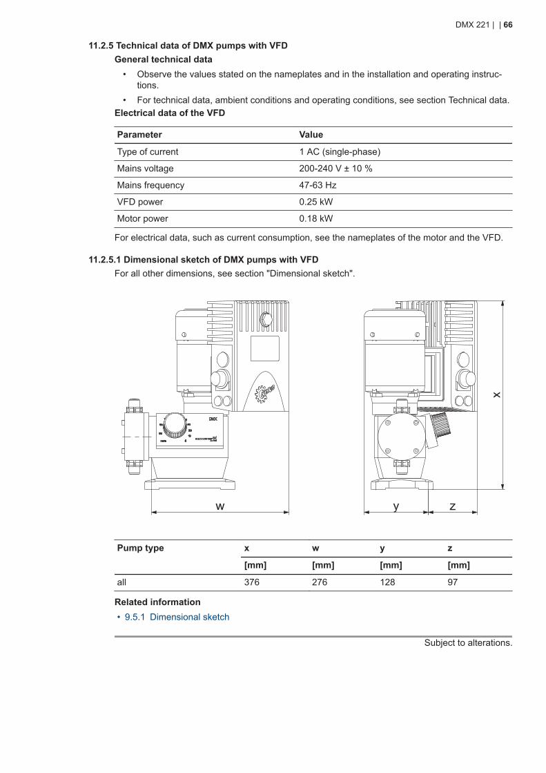
11.2.5 Technical data of DMX pumps with VFDGeneral technical data
• Observe the values stated on the nameplates and in the installation and operating instruc-tions.
• For technical data, ambient conditions and operating conditions, see section Technical data.Electrical data of the VFD
Parameter Value
Type of current 1 AC (single-phase)
Mains voltage 200-240 V ± 10 %
Mains frequency 47-63 Hz
VFD power 0.25 kW
Motor power 0.18 kW
For electrical data, such as current consumption, see the nameplates of the motor and the VFD.
11.2.5.1 Dimensional sketch of DMX pumps with VFDFor all other dimensions, see section "Dimensional sketch".
Pump type x w y z
[mm] [mm] [mm] [mm]
all 376 276 128 97
Related information• 9.5.1 Dimensional sketch
Subject to alterations.
DMX 221 | | 66

A.1. Curves
DMX 4-10 (50 Hz) Q0 = 3 bar
0
1
2
3
4
5
6
0 10 20 30 40 50 60 70 80 90 100h [%]
Q [l/h]
3 bar
10 bar
0
1
2
3
4
5
6
0 10 20 30 40 50 60 70 80 90 100h [%]
Q [l/h]
10 bar
3 bar
DMX 4-10 (60 Hz) Q0 = 3 bar
0
2
4
6
8
10
0 10 20 30 40 50 60 70 80 90 100h [%]
Q [l/h]
3 bar
10 bar
DMX 7-10 (50 Hz) Q0 = 3 bar
0
2
4
6
8
10
0 10 20 30 40 50 60 70 80 90 100h [%]
Q [l/h]
10 bar
3 bar
DMX 7-10 (60 Hz) Q0 = 3 bar
DMX 7,2-16 (50 Hz) Q0 = 3 bar
0
2
4
6
8
10
12
0 10 20 30 40 50 60 70 80 90 100h [%]
Q [l/h]
3 bar
16 bar
0
2
4
6
8
10
12
0 10 20 30 40 50 60 70 80 90 100h [%]
Q [l/h]
DMX 7,2-16 (60 Hz) Q0 = 3 bar
3 bar
16 bar
0
2
4
6
8
10
12
0 10 20 30 40 50 60 70 80 90 100h [%]
Q [l/h]
3 bar
10 bar
DMX 9-10 (50 Hz) Q0 = 3 bar
DMX 221 | | 67
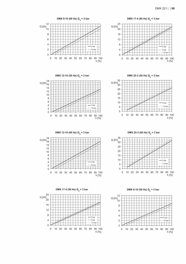
0
2
4
6
8
10
12
0 10 20 30 40 50 60 70 80 90 100h [%]
Q [l/h]
DMX 9-10 (60 Hz) Q0 = 3 bar
3 bar
10 bar
DMX 12-10 (50 Hz) Q0 = 3 bar
02468
1012141618
0 10 20 30 40 50 60 70 80 90 100h [%]
Q [l/h]
3 bar10 bar
DMX 12-10 (60 Hz) Q0 = 3 bar
02468
1012141618
0 10 20 30 40 50 60 70 80 90 100h [%]
Q [l/h]
3 bar
10 bar
DMX 17-4 (50 Hz) Q0 = 3 bar
0
4
8
12
16
20
24
0 10 20 30 40 50 60 70 80 90 100h [%]
Q [l/h]
3 bar4 bar1.5 bar
DMX 17-4 (60 Hz) Q0 = 3 bar
0
4
8
12
16
20
24
0 10 20 30 40 50 60 70 80 90 100h [%]
Q [l/h]
1.5 bar
3 bar
4 bar
DMX 25-3 (50 Hz) Q0 = 3 bar
0
5
10
15
20
25
30
35
0 10 20 30 40 50 60 70 80 90 100h [%]
Q [l/h]
1.5 bar
3 bar
DMX 25-3 (60 Hz) Q0 = 3 bar
0
5
10
15
20
25
30
35
0 10 20 30 40 50 60 70 80 90 100h [%]
Q [l/h]
3 bar
1.5 bar
DMX 8-10 (50 Hz) Q0 = 3 bar
0
2
4
6
8
10
12
0 10 20 30 40 50 60 70 80 90 100h [%]
Q [l/h]
3 bar10 bar
DMX 221 | | 68
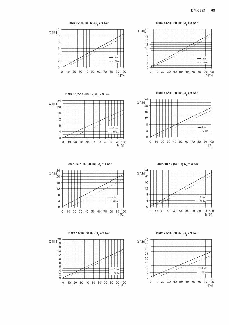
DMX 8-10 (60 Hz) Q0 = 3 bar
0
2
4
6
8
10
12
0 10 20 30 40 50 60 70 80 90 100h [%]
Q [l/h]
3 bar
10 bar
DMX 13,7-16 (50 Hz) Q0 = 3 bar
0
4
8
12
16
20
24
0 10 20 30 40 50 60 70 80 90 100h [%]
Q [l/h]
3 bar
16 bar
DMX 13,7-16 (60 Hz) Q0 = 3 bar
0
4
8
12
16
20
24
0 10 20 30 40 50 60 70 80 90 100h [%]
Q [l/h]
16bar
3bar
3 bar
16 bar
DMX 14-10 (50 Hz) Q0 = 3 bar
02468
101214161820
0 10 20 30 40 50 60 70 80 90 100h [%]
Q [l/h]
3 bar
10 bar
DMX 14-10 (60 Hz) Q0 = 3 bar
02468
101214161820
0 10 20 30 40 50 60 70 80 90 100h [%]
Q [l/h]
3 bar
10 bar
DMX 18-10 (50 Hz) Q0 = 3 bar
0
4
8
12
16
20
24
0 10 20 30 40 50 60 70 80 90 100h [%]
Q [l/h]
3 bar10 bar
DMX 18-10 (60 Hz) Q0 = 3 bar
0
4
8
12
16
20
24
0 10 20 30 40 50 60 70 80 90 100h [%]
Q [l/h]
3 bar
10 bar
DMX 26-10 (50 Hz) Q0 = 3 bar
05
10152025303540
0 10 20 30 40 50 60 70 80 90 100h [%]
Q [l/h]
3 bar
10 bar
DMX 221 | | 69
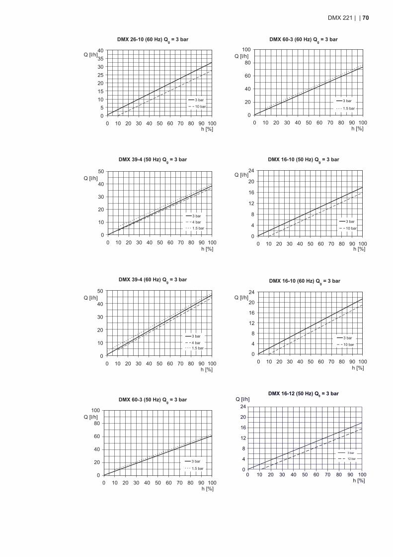
DMX 26-10 (60 Hz) Q0 = 3 bar
05
10152025303540
0 10 20 30 40 50 60 70 80 90 100h [%]
Q [l/h]
3 bar
10 bar
DMX 39-4 (50 Hz) Q0 = 3 bar
0
10
20
30
40
50
0 10 20 30 40 50 60 70 80 90 100h [%]
Q [l/h]
3 bar4 bar1.5 bar
DMX 39-4 (60 Hz) Q0 = 3 bar
0
10
20
30
40
50
0 10 20 30 40 50 60 70 80 90 100h [%]
Q [l/h]
1.5 bar
3 bar
4 bar
DMX 60-3 (50 Hz) Q0 = 3 bar
0
20
40
60
80
100
0 10 20 30 40 50 60 70 80 90 100h [%]
Q [l/h]
1.5 bar
3 bar
DMX 60-3 (60 Hz) Q0 = 3 bar
0
20
40
60
80
100
0 10 20 30 40 50 60 70 80 90 100h [%]
Q [l/h]
3 bar
1.5 bar
DMX 16-10 (50 Hz) Q0 = 3 bar
0
4
8
12
16
20
24
0 10 20 30 40 50 60 70 80 90 100h [%]
Q [l/h]
3 bar
10 bar
DMX 16-10 (60 Hz) Q0 = 3 bar
0
4
8
12
16
20
24
0 10 20 30 40 50 60 70 80 90 100h [%]
Q [l/h]
3 bar
10 bar
h [%]
Q [l/h]DMX 16-12 (50 Hz) Q0 = 3 bar
0
4
8
12
16
20
24
0 10 20 30 40 50 60 70 80 90 100
12 bar
3 bar
DMX 221 | | 70
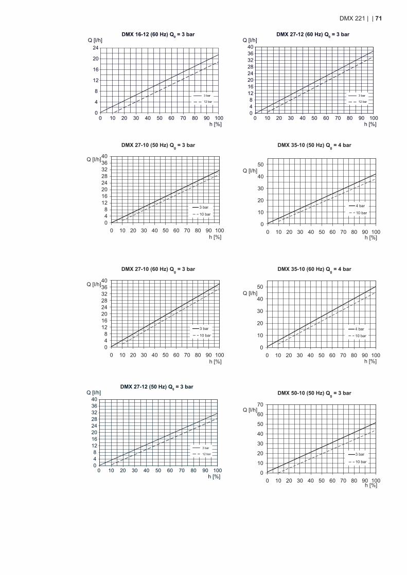
h [%]
Q [l/h]DMX 16-12 (60 Hz) Q0 = 3 bar
0
4
8
12
16
20
24
0 10 20 30 40 50 60 70 80 90 100
12 bar
3 bar
DMX 27-10 (50 Hz) Q0 = 3 bar
048
1216202428323640
0 10 20 30 40 50 60 70 80 90 100h [%]
Q [l/h]
3 bar
10 bar
DMX 27-10 (60 Hz) Q0 = 3 bar
048
1216202428323640
0 10 20 30 40 50 60 70 80 90 100h [%]
Q [l/h]
3 bar
10 bar
h [%]
Q [l/h]DMX 27-12 (50 Hz) Q0 = 3 bar
048
1216202428323640
0 10 20 30 40 50 60 70 80 90 100
12 bar
3 bar
h [%]
Q [l/h]DMX 27-12 (60 Hz) Q0 = 3 bar
048
1216202428323640
0 10 20 30 40 50 60 70 80 90 100
12 bar
3 bar
DMX 35-10 (50 Hz) Q0 = 4 bar
0
10
20
30
40
50
0 10 20 30 40 50 60 70 80 90 100h [%]
Q [l/h]
4 bar
10 bar
DMX 35-10 (60 Hz) Q0 = 4 bar
0
10
20
30
40
50
0 10 20 30 40 50 60 70 80 90 100h [%]
Q [l/h]
4 bar
10 bar
DMX 50-10 (50 Hz) Q0 = 3 bar
0
10
20
30
40
50
60
70
0 10 20 30 40 50 60 70 80 90 100h [%]
Q [l/h]
3 bar
10 bar
DMX 221 | | 71
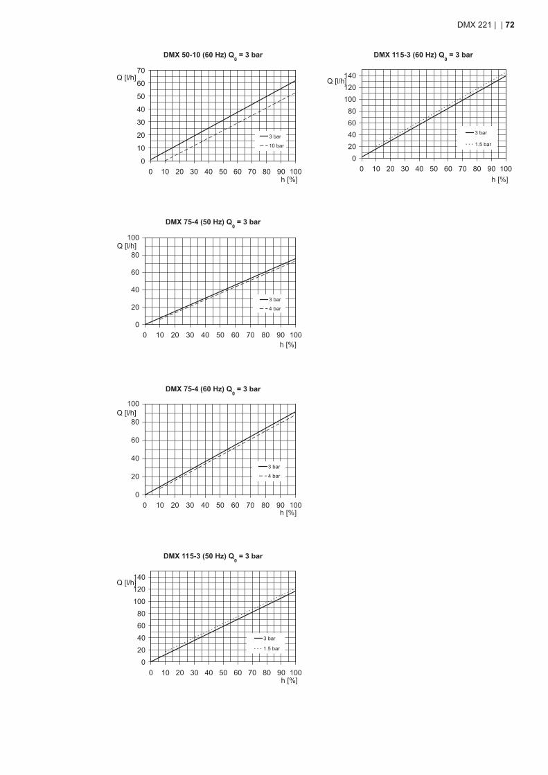
DMX 50-10 (60 Hz) Q0 = 3 bar
0
10
20
30
40
50
60
70
0 10 20 30 40 50 60 70 80 90 100h [%]
Q [l/h]
3 bar
10 bar
DMX 75-4 (50 Hz) Q0 = 3 bar
0
20
40
60
80
100
0 10 20 30 40 50 60 70 80 90 100h [%]
Q [l/h]
3 bar
4 bar
DMX 75-4 (60 Hz) Q0 = 3 bar
0
20
40
60
80
100
0 10 20 30 40 50 60 70 80 90 100h [%]
Q [l/h]
3 bar
4 bar
DMX 115-3 (50 Hz) Q0 = 3 bar
0
20
40
60
80
100
120
140
0 10 20 30 40 50 60 70 80 90 100h [%]
Q [l/h]
1.5 bar
3 bar
DMX 115-3 (60 Hz) Q0 = 3 bar
020406080
100120140
0 10 20 30 40 50 60 70 80 90 100h [%]
Q [l/h]
3 bar
1.5 bar
DMX 221 | | 72
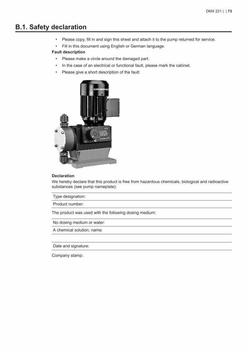
B.1. Safety declaration• Please copy, fill in and sign this sheet and attach it to the pump returned for service.• Fill in this document using English or German language.
Fault description• Please make a circle around the damaged part.• In the case of an electrical or functional fault, please mark the cabinet.• Please give a short description of the fault:
DeclarationWe hereby declare that this product is free from hazardous chemicals, biological and radioactivesubstances (see pump nameplate):
Type designation:
Product number:
The product was used with the following dosing medium:
No dosing medium or water:
A chemical solution, name:
Date and signature:
Company stamp:
DMX 221 | | 73
ArgentinaBombas GRUNDFOS de Argentina S.A.Ruta Panamericana km. 37.500 Centro In-dustrial Garin1619 - Garín Pcia. de B.A.Phone: +54-3327 414 444Telefax: +54-3327 411 111
AustraliaGRUNDFOS Pumps Pty. Ltd.P.O. Box 2040Regency ParkSouth Australia 5942Phone: +61-8-8461-4611Telefax: +61-8-8340-0155
AustriaGRUNDFOS Pumpen Vertrieb Ges.m.b.H.Grundfosstraße 2A-5082 Grödig/SalzburgPhone: +43-6246-883-0Telefax: +43-6246-883-30
BelgiumN.V. GRUNDFOS Bellux S.A.Boomsesteenweg 81-83B-2630 AartselaarPhone: +32-3-870 7300Telefax: +32-3-870 7301
BelarusПредставительство ГРУНДФОС в Минске220125, Минск, ул. Шафарнянская, 11, оф.56Phone: +7 (375 17) 286 39 72, 286 39 73Telefax: +7 (375 17) 286 39 71E-mail: [email protected]
Bosnia and HerzegovinaGRUNDFOS SarajevoTrg Heroja 16BiH-71000 SarajevoPhone: +387 33 713 290Telefax: +387 33 659 079E-mail: [email protected]
BrazilBOMBAS GRUNDFOS DO BRASILAv. Humberto de Alencar Castelo Branco,630CEP 09850 - 300São Bernardo do Campo - SPPhone: +55-11 4393 5533Telefax: +55-11 4343 5015
BulgariaGrundfos Bulgaria EOODSlatina DistrictIztochna Tangenta street no. 100BG - 1592 SofiaPhone: +359 2 49 22 200Telefax: +359 2 49 22 201E-mail: [email protected]
CanadaGRUNDFOS Canada Inc.2941 Brighton RoadOakville, OntarioL6H 6C9Phone: +1-905 829 9533Telefax: +1-905 829 9512
ChinaGRUNDFOS Pumps (Shanghai) Co. Ltd.10F The Hub, No. 33 Suhong RoadMinhang DistrictShanghai 201106 PRCPhone: +86-21 6122 5222Telefax: +86-21 6122 5333
China Grundfos AlldosGrundfos AlldosDosing & DisinfectionALLDOS (Shanghai) Water Technology Co.Ltd.West Unit, 1 Floor, No. 2 Building (T 4-2)278 Jinhu Road, Jin Qiao Export ProcessingZonePudong New AreaShanghai, 201206Phone: +86 21 5055 1012Telefax: +86 21 5032 0596E-mail: [email protected]
CroatiaGRUNDFOS CROATIA d.o.o.Cebini 37, BuzinHR-10010 ZagrebPhone: +385 1 6595 400Telefax: +385 1 6595 499
Czech RepublicGRUNDFOS Sales Czechia and Slovakias.r.o.Čajkovského 21779 00 OlomoucPhone: +420-585-716 111
DenmarkGRUNDFOS DK A/SMartin Bachs Vej 3DK-8850 BjerringbroPhone: +45-87 50 50 50Telefax: +45-87 50 51 51E-mail: [email protected]
EstoniaGRUNDFOS Pumps Eesti OÜPeterburi tee 92G11415 TallinnPhone: + 372 606 1690Telefax: + 372 606 1691
FinlandOY GRUNDFOS Pumput ABTrukkikuja 1FI-01360 VantaaPhone: +358-(0)207 889 500
FrancePompes GRUNDFOS Distribution S.A.Parc d’Activités de Chesnes57, rue de MalacombeF-38290 St. Quentin Fallavier (Lyon)Phone: +33-4 74 82 15 15Telefax: +33-4 74 94 10 51
GermanyGRUNDFOS GMBHSchlüterstr. 3340699 ErkrathPhone: +49-(0) 211 929 69-0Telefax: +49-(0) 211 929 69-3799E-mail: [email protected] in Deutschland: [email protected]
Germany Grundfos AlldosGRUNDFOS Water Treatment GmbHReetzstraße 85D-76327 Pfinztal (Söllingen)Phone: +49 7240 61-0Telefax: +49 7240 61-177E-mail: [email protected]
GreeceGRUNDFOS Hellas A.E.B.E.20th km. Athinon-Markopoulou Av.P.O. Box 71GR-19002 PeaniaPhone: +0030-210-66 83 400Telefax: +0030-210-66 46 273
Hong KongGRUNDFOS Pumps (Hong Kong) Ltd.Unit 1, Ground floor, Siu Wai Industrial Centre29-33 Wing Hong Street & 68 King LamStreet, Cheung Sha WanKowloonPhone: +852-27861706 / 27861741Telefax: +852-27858664
HungaryGRUNDFOS Hungária Kft.Park u. 8H-2045 TörökbálintPhone: +36-23 511 110Telefax: +36-23 511 111
IndiaGRUNDFOS Pumps India Private Limited118 Old Mahabalipuram RoadThoraipakkamChennai 600 097Phone: +91-44 4596 6800
IndonesiaPT GRUNDFOS PompaGraha Intirub Lt. 2 & 3Jln. Cililitan Besar No.454. Makasar, JakartaTimurID-Jakarta 13650Phone: +62 21-469-51900Telefax: +62 21-460 6910 / 460 6901
IrelandGRUNDFOS (Ireland) Ltd.Unit A, Merrywell Business ParkBallymount Road LowerDublin 12Phone: +353-1-4089 800Telefax: +353-1-4089 830
ItalyGRUNDFOS Pompe Italia S.r.l.Via Gran Sasso 4I-20060 Truccazzano (Milano)Phone: +39-02-95838112Telefax: +39-02-95309290 / 95838461
JapanGRUNDFOS Pumps K.K.1-2-3, Shin-Miyakoda, Kita-kuHamamatsu431-2103 JapanPhone: +81 53 428 4760Telefax: +81 53 428 5005
KoreaGRUNDFOS Pumps Korea Ltd.6th Floor, Aju Building 679-5Yeoksam-dong, Kangnam-ku, 135-916Seoul, KoreaPhone: +82-2-5317 600Telefax: +82-2-5633 725
LatviaSIA GRUNDFOS Pumps LatviaDeglava biznesa centrsAugusta Deglava ielā 60LV-1035, Rīga,Phone: + 371 714 9640, 7 149 641Telefax: + 371 914 9646
LithuaniaGRUNDFOS Pumps UABSmolensko g. 6LT-03201 VilniusPhone: + 370 52 395 430Telefax: + 370 52 395 431
MalaysiaGRUNDFOS Pumps Sdn. Bhd.7 Jalan Peguam U1/25Glenmarie Industrial Park40150 Shah Alam, SelangorPhone: +60-3-5569 2922Telefax: +60-3-5569 2866
MexicoBombas GRUNDFOS de MéxicoS.A. de C.V.Boulevard TLC No. 15Parque Industrial Stiva AeropuertoApodaca, N.L. 66600Phone: +52-81-8144 4000Telefax: +52-81-8144 4010
NetherlandsGRUNDFOS NetherlandsVeluwezoom 351326 AE AlmerePostbus 220151302 CA ALMEREPhone: +31-88-478 6336Telefax: +31-88-478 6332E-mail: [email protected]
New ZealandGRUNDFOS Pumps NZ Ltd.17 Beatrice Tinsley CrescentNorth Harbour Industrial EstateAlbany, AucklandPhone: +64-9-415 3240Telefax: +64-9-415 3250
NorwayGRUNDFOS Pumper A/SStrømsveien 344Postboks 235, LeirdalN-1011 OsloPhone: +47-22 90 47 00Telefax: +47-22 32 21 50
PolandGRUNDFOS Pompy Sp. z o.o.ul. Klonowa 23Baranowo k. PoznaniaPL-62-081 PrzeźmierowoPhone: (+48-61) 650 13 00Telefax: (+48-61) 650 13 50
PortugalBombas GRUNDFOS Portugal, S.A.Rua Calvet de Magalhães, 241Apartado 1079P-2770-153 Paço de ArcosPhone: +351-21-440 76 00Telefax: +351-21-440 76 90
RomaniaGRUNDFOS Pompe România SRLBd. Biruintei, nr 103Pantelimon county IlfovPhone: +40 21 200 4100Telefax: +40 21 200 4101E-mail: [email protected]
RussiaООО Грундфос Россия 109544г. Москва, ул. Школьная, 39Phone: (+7) 495 564-88-00 (495) 737-30-00Telefax: (+7) 495 564 88 11E-mail: [email protected]
SerbiaGRUNDFOS Predstavništvo BeogradDr. Milutina Ivkovića 2a/29YU-11000 BeogradPhone: +381 11 26 47 877 / 11 26 47 496Telefax: +381 11 26 48 340
SingaporeGRUNDFOS (Singapore)Pte. Ltd.25 Jalan TukangSingapore 619264Phone: +65-6681 9688Telefax: +65-6681 9689
SlovakiaGRUNDFOS s.r.o.Prievozská 4D 821 09 BRATISLAVAPhone: +421 2 5020 1426sk.grundfos.com
SloveniaGRUNDFOS LJUBLJANA, d.o.o.Leskoškova 9e, 1122 LjubljanaPhone: +386 (0) 1 568 06 10Telefax: +386 (0)1 568 0619E-mail: [email protected]
South AfricaGRUNDFOS (PTY) LTDCorner Mountjoy and George Allen RoadsWilbart Ext. 2, Bedfordview 2008Phone: (+27) 11 579 4800Telefax: (+27) 11 455 6066E-mail: [email protected]
SpainBombas GRUNDFOS España S.A.Camino de la Fuentecilla, s/nE-28110 Algete (Madrid)Phone: +34-91-848 8800Telefax: +34-91-628 0465
SwedenGRUNDFOS AB(Box 333) Lunnagårdsgatan 6431 24 MölndalPhone: +46 31 332 23 000Telefax: +46 31 331 94 60
SwitzerlandGRUNDFOS Pumpen AGBruggacherstrasse 10CH-8117 Fällanden/ZHPhone: +41-44-806 8111Telefax: +41-44-806 8115
Switzerland Grundfos AlldosGRUNDFOS ALLDOS International AGSchönmattstraße 4CH-4153 ReinachPhone: +41-61-717 5555Telefax: +41-61-717 5500E-mail: [email protected]
TaiwanGRUNDFOS Pumps (Taiwan) Ltd.7 Floor, 219 Min-Chuan RoadTaichung, Taiwan, R.O.C.Phone: +886-4-2305 0868Telefax: +886-4-2305 0878
ThailandGRUNDFOS (Thailand) Ltd.92 Chaloem Phrakiat Rama 9 RoadDokmai, Pravej, Bangkok 10250Phone: +66-2-725 8999Telefax: +66-2-725 8998
TurkeyGRUNDFOS POMPA San. ve Tic. Ltd. Sti.Gebze Organize Sanayi BölgesiIhsan dede Caddesi2. yol 200. Sokak No. 20441490 Gebze/ KocaeliPhone: +90 - 262-679 7979Telefax: +90 - 262-679 7905E-mail: [email protected]
UkraineБізнес Центр ЄвропаСтоличне шосе, 103м. Київ, 03131, УкраїнаPhone: (+38 044) 237 04 00Telefax: (+38 044) 237 04 01E-mail: [email protected]
United Arab EmiratesGRUNDFOS Gulf DistributionP.O. Box 16768Jebel Ali Free Zone, DubaiPhone: +971 4 8815 166Telefax: +971 4 8815 136
United KingdomGRUNDFOS Pumps Ltd.Grovebury RoadLeighton Buzzard/Beds. LU7 4TLPhone: +44-1525-850000Telefax: +44-1525-850011
U.S.A.GRUNDFOS Pumps Corporation17100 West 118th Terrace, OlatheKansas 66061Phone: +1-913-227-3400Telefax: +1-913-227-3500
UzbekistanGrundfos Tashkent, UzbekistanThe Representative Office of Grundfos Ka-zakhstan in Uzbekistan38a, Oybek street, TashkentPhone: (+998) 71 150 3290 / 71 150 3291Telefax: (+998) 71 150 3292
Revision InfoLast revised on 02.09.2016

91834765 0317ECM: 1203452
www.grundfos.com
The
nam
e G
rund
fos,
the
Gru
ndfo
s lo
go, a
nd b
e th
ink
inno
vate
are
regi
ster
ed tr
adem
arks
ow
ned
by G
rund
fos
Hol
ding
A/S
or G
rund
fos
A/S
, Den
mar
k. A
ll rig
hts
rese
rved
wor
ldw
ide.
© C
opyr
ight
Gru
ndfo
s H
oldi
ng A
/S