DMU Optimizer Preface - CATIAcatia.com.pl/tutorial/z2/dmu_optimizer.pdf · Using This Guide This...
49
DMU Optimizer Preface Getting Started Basic Tasks Advanced Tasks Workbench Description © Dassault Systèmes 1994-99. All rights reserved.
Transcript of DMU Optimizer Preface - CATIAcatia.com.pl/tutorial/z2/dmu_optimizer.pdf · Using This Guide This...

DMU Optimizer
Preface
Getting Started
Basic Tasks
Advanced Tasks
Workbench Description
© Dassault Systèmes 1994-99. All rights reserved.
PrefaceDMU OPTIMIZER 2 (DOP) is a product dedicated to improve user's productivity bycomputing an optimized representation of data for mockup verification in the context ofthe immersive and collaborative design review environment of the full digital mockup.DMU OPTIMIZER 2 (DOP) facilitates the full integration of Digital Mockup centricprocesses within the global engineering environment of the customer.
DMU OPTIMIZER 2 is a dedicated DMU Navigator workbench and is available on bothUNIX and Windows NT environments.
This guide is organized as follows:Getting Started
Provides a scenario allowing you to get acquainted with the product.Basic Tasks
Provides a step-by-step guide for using DMU Optimizer. Useful tips are given forgetting the most out of the product.
Workbench Description
Describes menu commands and workbench toolbars that are useful for DMUOptimizer.

Using This GuideThis guide is intended for the user who needs to quickly become familiar with DMUOptimizer. The user should be familiar with basic DMU Navigator Version 5 conceptssuch as document windows, standard and view toolbars.
To get the most out of this guide, we suggest you start reading and performing thestep-by-step tutorial "Getting Started".
>The next sections present main capabilities in the form of user's tasks. It may be agood idea to take a look at the section describing the menus and toolbars.
Where to Find More InformationPrior to reading this book, we recommend that you read the DMU Navigator User'sGuide.
You may also like to read the following complementary DMU Navigator product guides,for which the appropriate license is required:
DMU Fitting Simulator User's GuideDMU Space Analysis User's Guide.

Getting StartedBefore getting into the detailed instructions for using DMU Optimizer, thefollowing tutorial aims at giving you a feel of what you can do with the product. Itprovides a step-by-step scenario showing you how to use key functions.The main tasks described in this section are:
Tasks

Starting a DMU Optimizer SessionBefore starting this scenario, you should be familiar with the basic commands common toall workbenches. These are described in the DMU Navigator User's Guide.This first task will show you how to enter the DMU Optimizer workbench and select yourmodels
1. Select Digital Mockup -> DMU Optimizer from the Start menu
The DMU Optimizer workbench is loaded and an empty document opens:
2. Select Insert -> Existing Component... from the menu bar.3. Select the desired model files by clicking the first one then shift-clicking the lastone you want.
Click Open to open the selected files.
The specification tree is displayed showing all the selected products.

Use the Fit All In icon to position the model geometry on the screen.
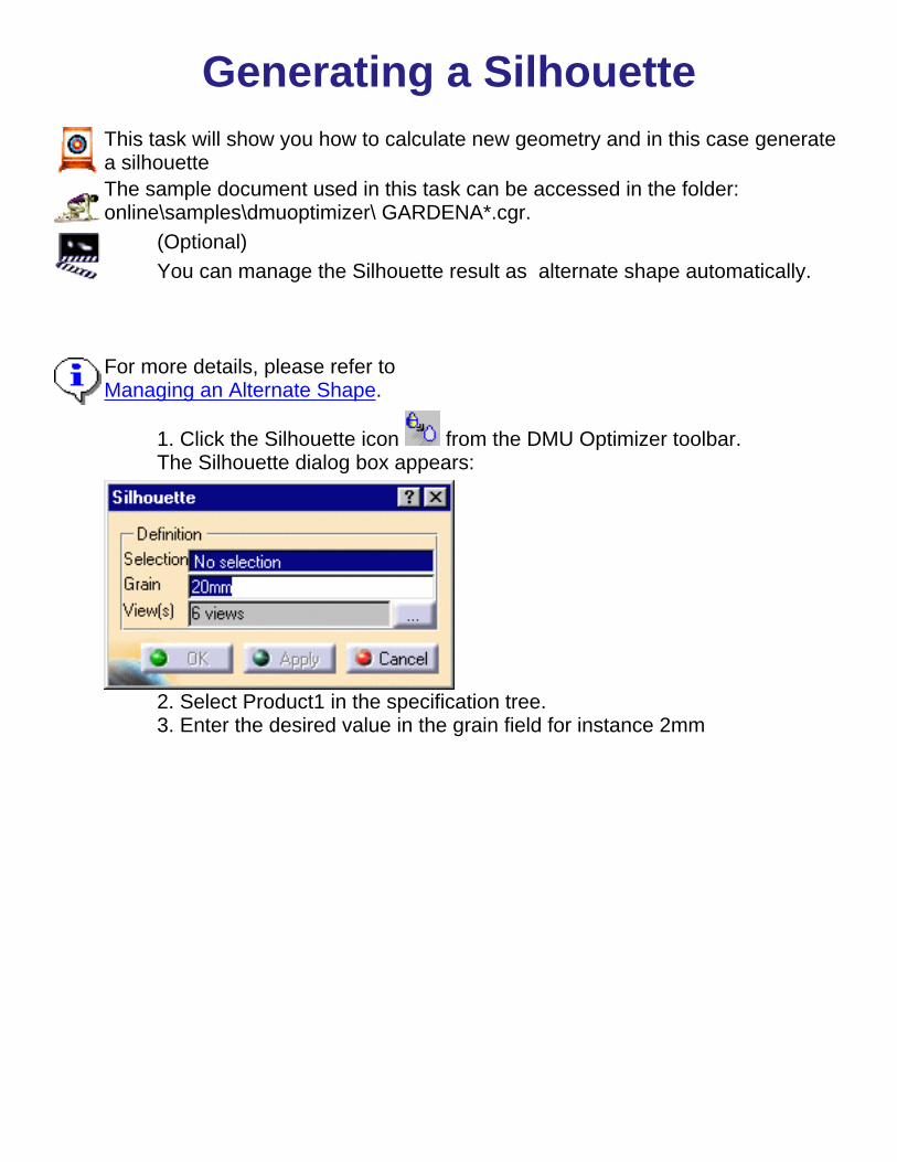
Generating a SilhouetteThis task will show you how to calculate new geometry and in this case generatea silhouetteThe sample document used in this task can be accessed in the folder:online\samples\dmuoptimizer\ GARDENA*.cgr.
(Optional)You can manage the Silhouette result as alternate shape automatically.
For more details, please refer toManaging an Alternate Shape.
1. Click the Silhouette icon from the DMU Optimizer toolbar.The Silhouette dialog box appears:
2. Select Product1 in the specification tree.3. Enter the desired value in the grain field for instance 2mm
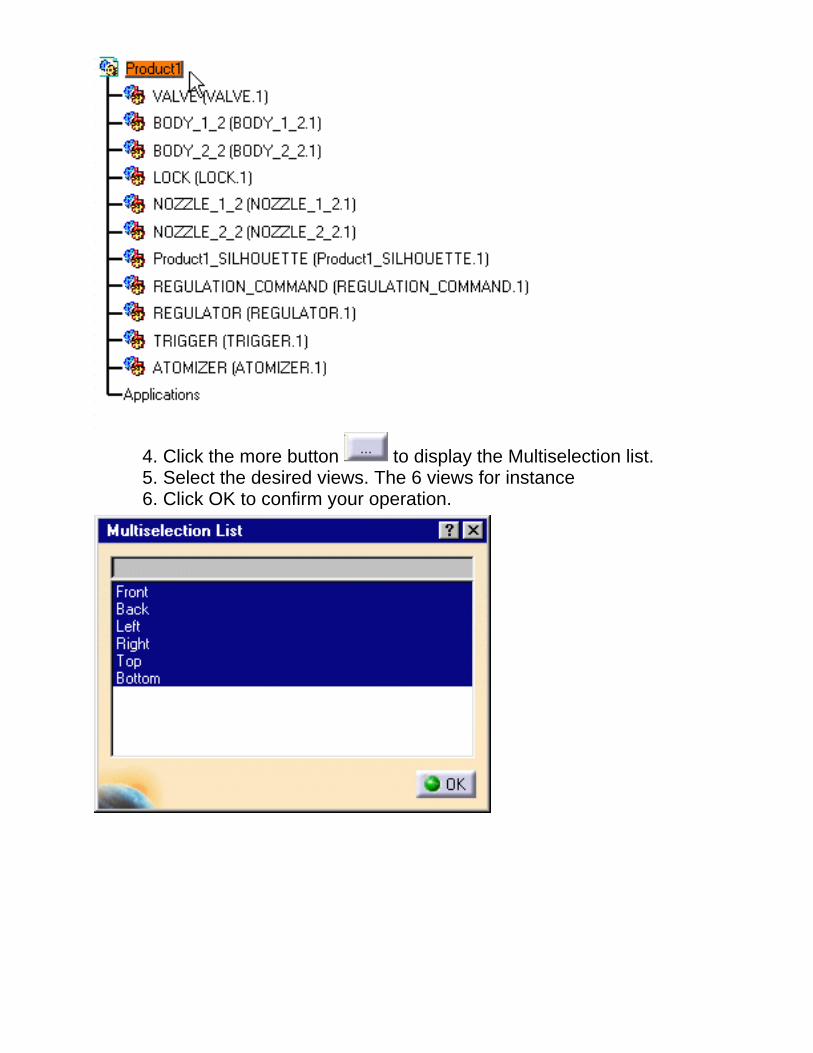
4. Click the more button to display the Multiselection list.5. Select the desired views. The 6 views for instance6. Click OK to confirm your operation.

7. Click the Apply buttonto obtain a silhouettepreviewThe progress bardisplays:
The Preview windowdisplay too.
DMN License:If you have a DMU Navigator license, you can define cameras and they areproposed in the multiselection dialog box.
8. Click OK to save the silhouette representation.


Generating a WrappingThis first task will show you how to generate a Wrapping representation.
The sample document used in this task can be accessed in the folder: online\samples\dmuoptimizer\ *.cgr.You activated
(Optional)You can manage your Wrapping result as alternate shape automatically. Please refer to Managingan Alternate Shape.1. Select Product 1 in the specification tree.
2.Click the Wrapping icon from the DMU Optimizertoolbar.The Silhouette dialog box appears:
3. Set the grain accuracy by entering a value, 4mm forexample.
Setting the RatioThe Ratio determines the wrapping representation. A lower setting results in a thinner wrappingcoverage4. Move the slider to the right to set the ratio to 0.50 forexample5. Click Apply to obtain a previewThe progress bar shows the computation
The preview window lets you see the resulting wrapping

6.Click OK.The Save As dialog box displays:7. Click Save.
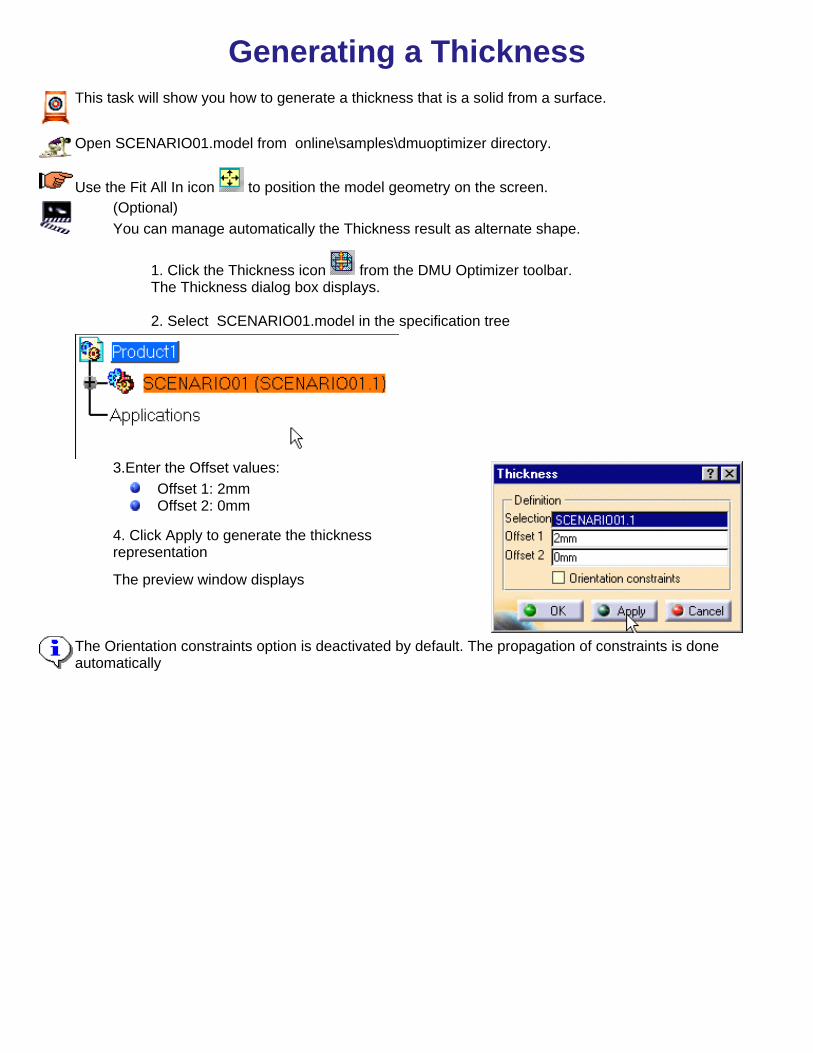
Generating a ThicknessThis task will show you how to generate a thickness that is a solid from a surface.
Open SCENARIO01.model from online\samples\dmuoptimizer directory.
Use the Fit All In icon to position the model geometry on the screen.(Optional)You can manage automatically the Thickness result as alternate shape.
1. Click the Thickness icon from the DMU Optimizer toolbar.The Thickness dialog box displays.
2. Select SCENARIO01.model in the specification tree
3.Enter the Offset values:Offset 1: 2mmOffset 2: 0mm
4. Click Apply to generate the thicknessrepresentation
The preview window displays
The Orientation constraints option is deactivated by default. The propagation of constraints is doneautomatically

5. Zoom to visualize better the thickness result :You are not satisfied with the result.
You are still in the Thickness command.

6. Click the undo icon to go back to the initialrepresentation.7. Activate the Orientation constraints option in thedialog box still displayed:8. Click ApplyThe Propagation of constraints is not complete.The surfaces concerned are highlighted.
9. Define constraints on the correspondingsurfaces:
Drag the cursor onto the surfaceWhen you are satisfied, click the left-handmouse button.The constraint is created
At anytime, you can delete a constraint, what you need to do is to click on the white squareNote that if you click th arrow, you invert the constraint orientation.
10. Click Apply when done. The surfaces are correctly positioned.
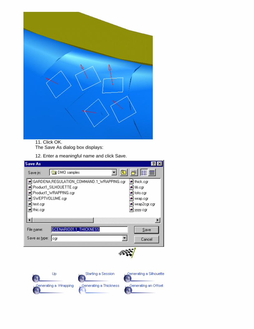
11. Click OK.The Save As dialog box displays:
12. Enter a meaningful name and click Save.

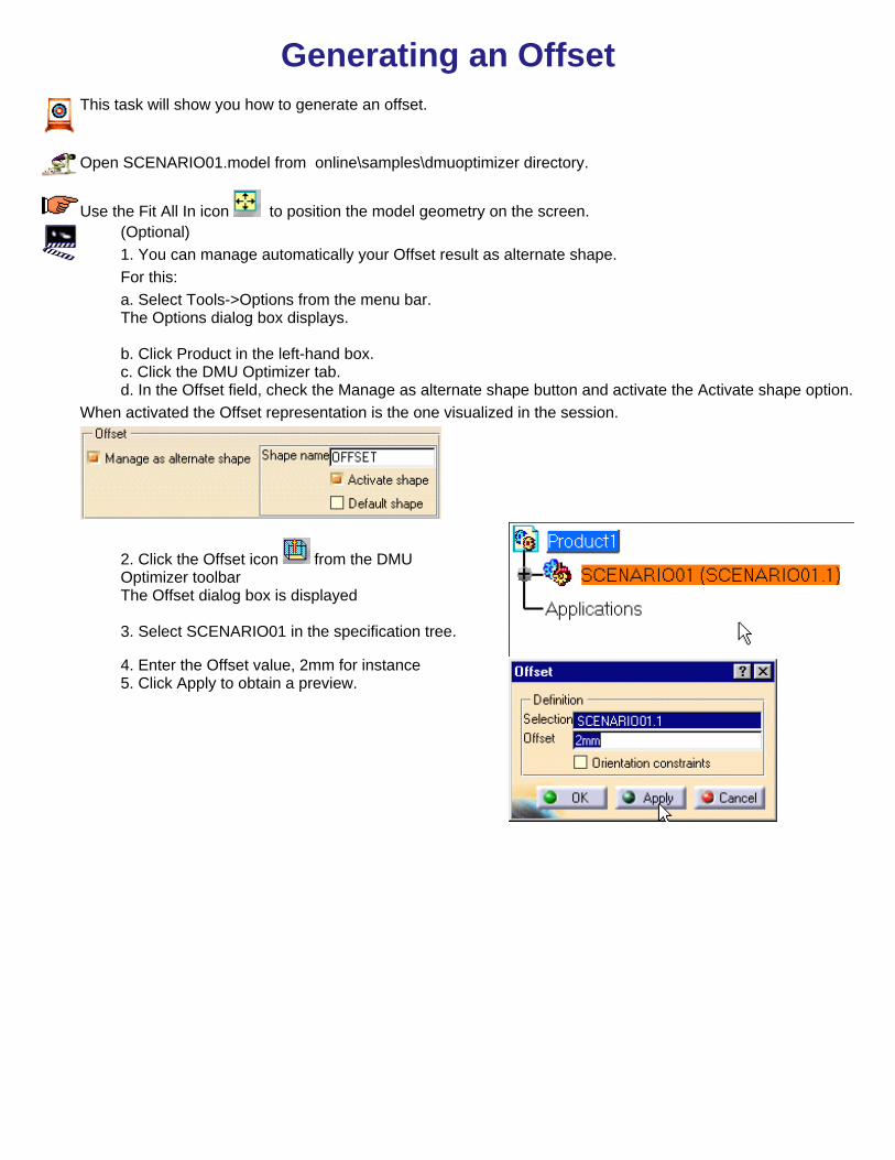
Generating an OffsetThis task will show you how to generate a thickness that is a solid from a surface.
Open SCENARIO01.model from online\samples\dmuoptimizer directory.
Use the Fit All In icon to position the model geometry on the screen.1. Make sure the Thickness is managed asalternate shape and activated.For this:a. Select Tools->Options from the menu bar.The Options dialog box displays.
b. Click Product in the left-hand box.c. Click the DMU Optimizer tab.d. In the Offset field, check the Manage asalternate shape button and activate theActivate shape option.
When activated the Offset representation is the onevisualized in the session.
2. Click the Offset icon from theDMU Optimizer toolbar.The Offset dialog box displays:
3. Select SCENARIO01 in thespecification tree.4. Enter the Offset value,2mm forinstance5. Click Apply to obtain a preview.

6. Click the undo icon to go back tothe initial representation.7. Activate the Orientation constraintsoption in the dialog box still displayed:8. Click Apply
Orientation ConstraintsThe Orientation constraints option is deactivated by default. (The propagation of defaultorientation constraints is done automatically).The constraints define the orientation of the offset (positive).
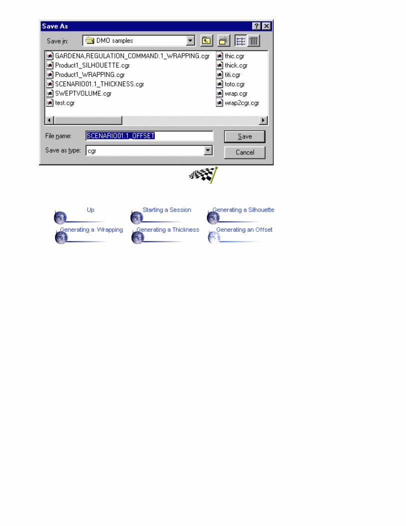
9. Click OK.The Save As dialog box displays:10. Enter a meaningful name and click Save.

Basic TasksThe table below lists the tasks you will find in this section.
Theme

Simplifying an AssemblyThe table below lists the tasks you will find in this section.
Tasks
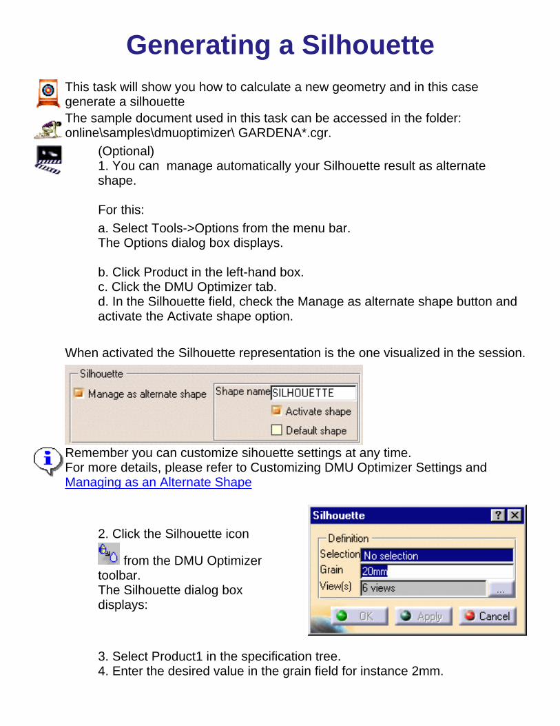
Generating a SilhouetteThis task will show you how to calculate a new geometry and in this casegenerate a silhouetteThe sample document used in this task can be accessed in the folder:online\samples\dmuoptimizer\ GARDENA*.cgr.
(Optional)1. You can manage automatically your Silhouette result as alternateshape.
For this:a. Select Tools->Options from the menu bar.The Options dialog box displays.
b. Click Product in the left-hand box.c. Click the DMU Optimizer tab.d. In the Silhouette field, check the Manage as alternate shape button andactivate the Activate shape option.
When activated the Silhouette representation is the one visualized in the session.
Remember you can customize sihouette settings at any time.For more details, please refer to Customizing DMU Optimizer Settings andManaging as an Alternate Shape
2. Click the Silhouette icon
from the DMU Optimizertoolbar.The Silhouette dialog boxdisplays:
3. Select Product1 in the specification tree.4. Enter the desired value in the grain field for instance 2mm.
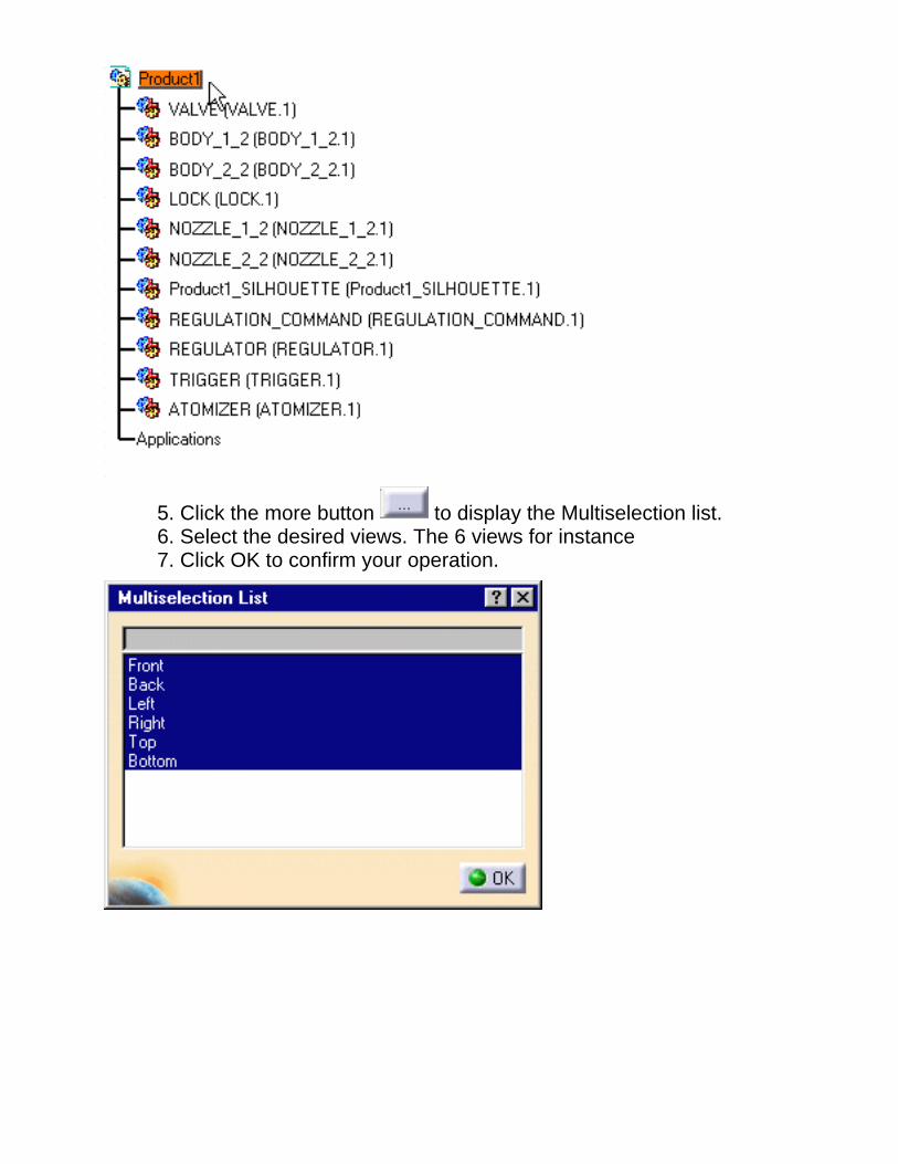
5. Click the more button to display the Multiselection list.6. Select the desired views. The 6 views for instance7. Click OK to confirm your operation.

8. Click the Apply button toobtain a silhouette previewThe progress bar displays:
The Preview window displaytoo.
DMN License:If you have a DMU Navigator license, you can define cameras and they areproposed in the multiselection dialog box .
9. Click OK to save the silhouette representation.


Generating a WrappingThis task will show you how to generate a Wrapping representation.
The sample document used in this task can be accessed in the folder:online\samples\dmuoptimizer\ *.cgr.
(Optional)1. You can automatically manage your Thickness result as alternate shape.
For this:a. Select Tools->Options from the menu bar.The Options dialog box displays.
b. Click Product in the left-hand box.c. Click the DMU Optimizer tab.d. In the Thickness field, check the Manage as alternate shape button and activate theActivate shape option.
When activated the Thickness representation is the one visualized in the session.
2. Select Product 1 in the specification tree
3. Click the Wrapping icon from the DMU Optimizer toolbar.The Silhouette dialog box displays:
4. Set the grain accuray by entering a value, 4mm for example.

Setting the RatioThe Ratio determines the wrapping representation. A lower value results in a thinner but less envelopping representation.5. Move the slider to the right to set the ratio to0.50 for example6. Click Apply to obtain a previewThe progress bar shows the computation
The preview window lets you see the resultingwrapping

7.Click OK.The Save As dialog box displays:8. Click Save.

Thickness and OffsetTasks

Generating a ThicknessThis task will show you how to generate a thickness that is a solid from a surface.
Open SCENARIO01.model from online\samples\dmuoptimizer directory.
Use the Fit All In icon to position the model geometry on the screen.(Optional)1. You can manage your Thickness result as alternate shapeautomatically.
For this:a. Select Tools->Options from the menu bar.The Options dialog box displays.
b. Click Product in the left-hand box.c. Click the DMU Optimizer tab.d. In the Thickness field, check the Manage as alternate shapebutton and activate the Activate shape option.
When activated the Thickness representation is the one visualized inthe session.
2. Click the Thickness icon from the DMU Optimizertoolbar.The Thickness dialog box displays.3. Select SCENARIO01.model in the specification tree
4. Enter the Offset values:Offset 1: 2mmOffset 2: 0mm
5. Click Apply to generate the thickness representation
The preview window displays
Orientation ConstraintsThe Orientation constraints option is deactivated by default. (The propagation of constraints is doneautomatically).The constraints define the orientation of the offset (positive).

6. Zoom to visualize better the thickness result :You are not satisfied with the result.
You are still in the Thickness command.
7. Click the Undo icon to go back to the initialrepresentation.8. Activate the Orientation constraints option in thedialog box still displayed:9. Click Apply

The Propagation of constraints is not complete. Thesurfaces concerned are highlighted.10. Define constraints on the corresponding surfaces:
Drag the cursor onto the surfaceWhen you are satisfied, click the left-hand mousebutton.The constraint is created
At anytime, you can delete a constraint, what you need to do is to click on the white squareNote that if you click the arrow, you invert the constraint orientation.
11. Click Apply when done. The result is correct : the calculation is based on the new orientationconstraints
12. Click OK.The Save As dialog box displays:13. Enter a meaningful name and click Save.

Generating an OffsetThis task will show you how to generate an offset.
Open SCENARIO01.model from online\samples\dmuoptimizer directory.
Use the Fit All In icon to position the model geometry on the screen.(Optional)1. You can manage automatically your Offset result as alternate shape.For this:a. Select Tools->Options from the menu bar.The Options dialog box displays.
b. Click Product in the left-hand box.c. Click the DMU Optimizer tab.d. In the Offset field, check the Manage as alternate shape button and activate the Activate shape option.
When activated the Offset representation is the one visualized in the session.
2. Click the Offset icon from the DMUOptimizer toolbarThe Offset dialog box is displayed
3. Select SCENARIO01 in the specification tree.
4. Enter the Offset value, 2mm for instance5. Click Apply to obtain a preview.

Orientation ConstraintsThe Orientation constraints option is deactivated by default. (The propagation of constraints is doneautomatically).The constraints define the orientation of the offset (positive).
6. Click the Undo icon to go back to theinitial representation.7. Activate the Orientation constraints option inthe dialog box still displayed:8. Click ApplyThe Propagation of constraints is not complete. The surfaces concerned are highlighted.
9. Define constraints on the corresponding surfaces:Drag the cursor onto the surfaceWhen you are satisfied, click the left-hand mouse button.The constraint is automatically created.
At anytime, you can delete a constraint, what you need to do is click on the white square.Note that if you click the arrow, you invert the constraint orientation.
10. Click Apply when done. The result is correct : the calculation is based on the new orientationconstraints

11. Click OK.The Save As dialog box is displayed:
12. Enter a meaningful name and click Save.

Advanced TasksThe table below lists the tasks you will find in this section.
Theme
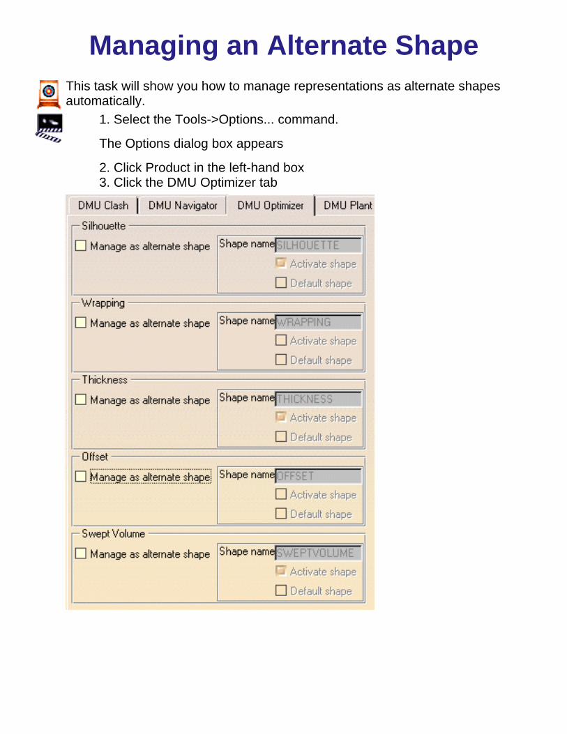
Managing an Alternate ShapeThis task will show you how to manage representations as alternate shapesautomatically.
1. Select the Tools->Options... command.
The Options dialog box appears
2. Click Product in the left-hand box3. Click the DMU Optimizer tab

3. Select the required representation, for example Offset.4. Customize the representation settings as required:
Manage as alternate shape : if activated, you manageautomatically your result as a new representationActivate Shape : if activated the Offset representation is theone visualized in the session.Default Shape : if activated the Default shape is the oneloaded when opening the product
5. Click Ok to confirm your operationAfter a new offset calculation, if you right-click the product and select Managerepresentations, the Manage representation dialog box is automatically updatedwith the offset representation.

Editing MacrosIf you perform a task repeatedly, you can take advantage of a macro to automate it. A macro is a series of functions,written in a scripting laguage, that you group in a single command to perform the requested task automaticallyThis task will show you how to edit a macro created in the DMU Optimizer
You stored your recorded macros in a text format file. For more details about recording, running macros please refer tothe Infrastucture User's Guide 1. You can easily modify the macro instructions specific to DMU Optimizer (strings of characters put in bold).Here is an example:
Thickness MacroTHICKNESS MACRO EXPLANATIONS
Language="VBSCRIPT"
Sub CATMain()CATIA.ActiveWindow.ActiveViewer.Viewpoint3D.ProjectionMode = 0CATIA.ActiveWindow.ActiveViewer.Reframe
Dim Product0 As AnyObjectSet Product0 = CATIA.ActiveDocument.GetItem ( "Product1" )Dim Product1 As AnyObjectSet Product1 = Product0.Products.Item ( "SCENARIO01.1" )
var2 = Product1.HasAMasterShapeRepresentation
var3 = Product1.HasAMasterShapeRepresentation
Name of the product selected for the thickness.
Enter a meaningful name if you wish to edit thename.
Dim OptimizerWorkBench4 As WorkbenchSet OptimizerWorkBench4 = CATIA.ActiveDocument.GetWorkbench( "OptimizerWorkBench" )
Dim var5 ( 5 )var5 ( 0 ) = 1686.914185var5 ( 1 ) = -687.232605var5 ( 2 ) = -30.685900var5 ( 3 ) = -0.006788var5 ( 4 ) = -0.173665var5 ( 5 ) = 0.984781Dim DMOThickness6 As DMOThicknessSet DMOThickness6 = OptimizerWorkBench4.Thicknesses.Add (Product1, 2.000000, -2.000000, 1, var5, "THICKNESS", 0, 0 )
Dim Document7 As AnyObjectSet Document7 = CATIA.Documents.Item ("SCENARIO±013±-±ZWISCHENSTUECK.1_THICKNESS.cgr" )
Document7.Activate
Product1 : corresponds to the selected product
2.000000, -2.000000, Gives the values of the offset1 and offset 2, you defined.
1 correspond to the number orientation constraints
var 5: defines the constraint coordinates:Constraint location point
var5 ( 0 ) = 1686.914185var5 ( 1 ) = -687.232605var5 ( 2 ) = -30.685900
Corresponding normal vector
var5 ( 3 ) = -0.006788var5 ( 4 ) = -0.173665var5 ( 5 ) = 0.984781
"THICKNESS": Name of the Alternate Shape

"" means the alternate shape option isdeactivated.
0,0 : refer to the shape representation settings
0 -> "Activate shape" option is deactivated
0 -> "Default Shape" option is deactivated
Please refer to Managing as an alternateshape for more details
Document7.SaveAs"E:\users\sbc\ADELE\sbcDPS3\SCENARIO01.1_THICKNESS.cgr"
CATIA.ActiveDocument.Activate
End Sub
Gives the location of the cgr file you saved.
Silhouette macro :
Dim var5 ( 17 )var5 ( 0 ) = 1.000000var5 ( 1 ) = 0.000000var5 ( 2 ) = 0.000000var5 ( 3 ) = -1.000000var5 ( 4 ) = 0.000000var5 ( 5 ) = 0.000000var5 ( 6 ) = 0.000000var5 ( 7 ) = 1.000000var5 ( 8 ) = 0.000000var5 ( 9 ) = 0.000000var5 ( 10 ) = -1.000000var5 ( 11 ) = 0.000000var5 ( 12 ) = 0.000000var5 ( 13 ) = 0.000000var5 ( 14 ) = 1.000000var5 ( 15 ) = 0.000000var5 ( 16 ) = 0.000000var5 ( 17 ) = -1.000000
Dim Silhouette6 As Silhouette
Set Silhouette6 = OptimizerWorkBench4.Silhouettes.Add (Product1, 20.000000, var5, "", 0, 0 )
Var 5: defines the viewpoints vector coordinates
Coordinates of the first viewpoint vector :
var5 ( 0 ) = 1.000000var5 ( 1 ) = 0.000000var5 ( 2 ) = 0.000000
and so on...

Workbench DescriptionThis section contains the description of the icons and menus which are specific to the DMU Optimizerworkbench.
The DMU Optimizer window looks like this: (click the sensitive areas to see the related documentation).
DMU Optimizer Menu Bar
DMU Otptimizer Toolbar
Sectioning Tools Toolbar

DMU Optimizer Menu BarHere we will present the various menus and menu commands that are specific toDMU Kinematics Simulator Version 5.
Start File Edit View Insert Tools Analyze Windows Help
Tasks corresponding to General menu commands are described in the DMU Version5 Infrastructure User's Guide.
EditFor... Description...
Undo Cancels the last action.
Redo Recovers the last action thatwas undone.
CutCopyPastePaste Special
Performs cutcopypaste andspecial paste operations.
Delete Deletes selected geometry.

Search Allows searching and selectingobjects.
Links Manages links to otherdocuments.
Properties Allows displaying and editingobject properties.
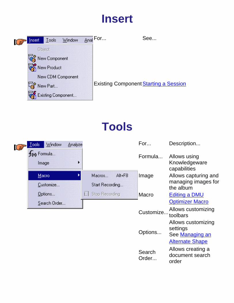
Insert
For... See...
Existing Component Starting a Session
ToolsFor... Description...
Formula... Allows using Knowledgewarecapabilities
Image Allows capturing andmanaging images forthe album
Macro Editing a DMUOptimizer Macro
Customize... Allows customizingtoolbars
Options...
Allows customizingsettingsSee Managing anAlternate Shape
SearchOrder...
Allows creating adocument searchorder

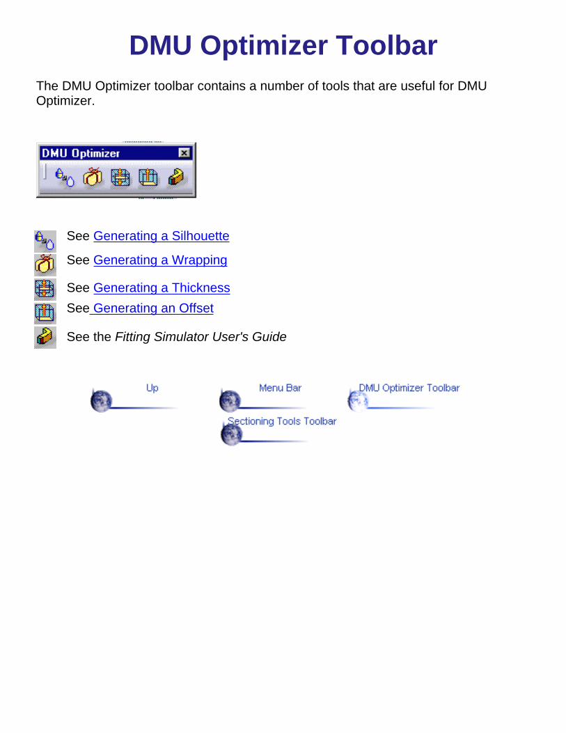
DMU Optimizer ToolbarThe DMU Optimizer toolbar contains a number of tools that are useful for DMUOptimizer.
See Generating a Silhouette
See Generating a Wrapping
See Generating a ThicknessSee Generating an Offset
See the Fitting Simulator User's Guide
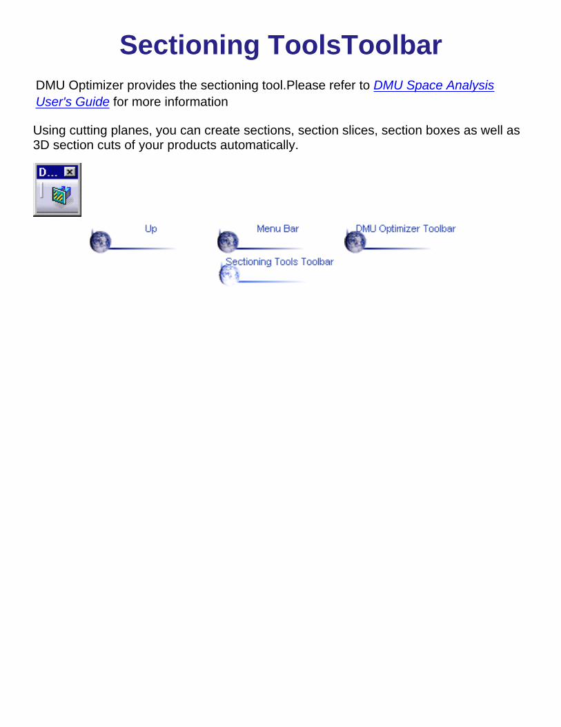
Sectioning ToolsToolbarDMU Optimizer provides the sectioning tool.Please refer to DMU Space AnalysisUser's Guide for more information
Using cutting planes, you can create sections, section slices, section boxes as well as3D section cuts of your products automatically.