DMG I 2015/16 CAD Tutorials - Técnico Lisboa - Autenticação · DMG I 2015/16 CAD Tutorials 1 ......
19
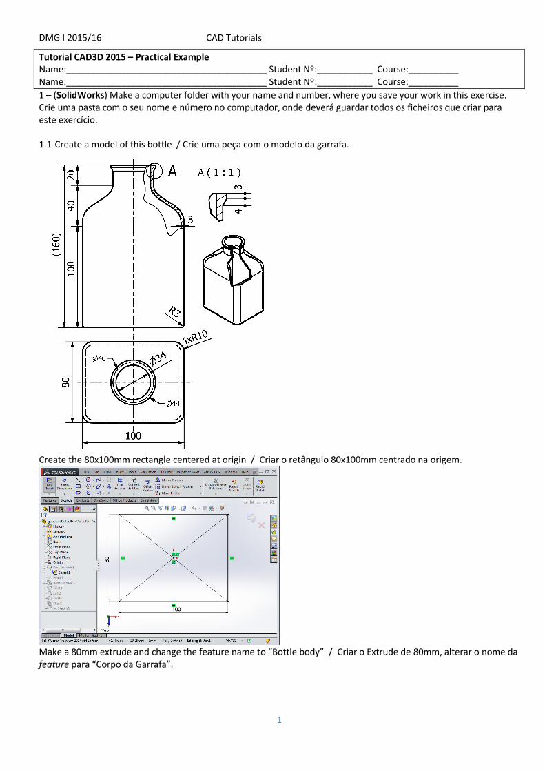
DMG I 2015/16 CAD Tutorials 1 Tutorial CAD3D 2015 – Practical Example Name:________________________________________ Student Nº:___________ Course:__________ Name:________________________________________ Student Nº:___________ Course:__________ 1 – (SolidWorks) Make a computer folder with your name and number, where you save your work in this exercise. Crie uma pasta com o seu nome e número no computador, onde deverá guardar todos os ficheiros que criar para este exercício. 1.1-Create a model of this bottle / Crie uma peça com o modelo da garrafa. Create the 80x100mm rectangle centered at origin / Criar o retângulo 80x100mm centrado na origem. Make a 80mm extrude and change the feature name to “Bottle body” / Criar o Extrude de 80mm, alterar o nome da feature para “Corpo da Garrafa”.
Transcript of DMG I 2015/16 CAD Tutorials - Técnico Lisboa - Autenticação · DMG I 2015/16 CAD Tutorials 1 ......
DMG I 2015/16 CAD Tutorials
1
Tutorial CAD3D 2015 – Practical Example Name:________________________________________ Student Nº:___________ Course:__________ Name:________________________________________ Student Nº:___________ Course:__________
1 – (SolidWorks) Make a computer folder with your name and number, where you save your work in this exercise. Crie uma pasta com o seu nome e número no computador, onde deverá guardar todos os ficheiros que criar para este exercício. 1.1-Create a model of this bottle / Crie uma peça com o modelo da garrafa.
Create the 80x100mm rectangle centered at origin / Criar o retângulo 80x100mm centrado na origem.
Make a 80mm extrude and change the feature name to “Bottle body” / Criar o Extrude de 80mm, alterar o nome da feature para “Corpo da Garrafa”.

DMG I 2015/16 CAD Tutorials
2
Create a new plane for the bottleneck cylinder. Click on the topo face and change distace to 40mm Plane1 will be used to sketch the bottleneck. / Criar um plano auxiliar para o cilindro do gargalo. Clique sobre a face e automaticamente surge a opção de distância, indique 40mm. O Plane1 será usado para desenhar o sketch do gargalo.

DMG I 2015/16 CAD Tutorials
3
Draw a 40mm diameter origin centered circle. Use “Smart Dimension”. Do a 20mm extrude and rename it to “Bottleneck”. / Desenhar uma circunferência, centrada na origem, com o diâmetro do gargalo (40mm). Use a ferramenta de cotagem “Smart Dimension”. Faça o extrude de 20mm. Altere o nome da feature para “Gargalo”.
Note the “Solid Bodies (2)” entry on the features tree, as the part has now two separate bodies. Do the 10mm radius fillet. / Note que aparece a “entrada” “Solid Bodies (2)” na árvore de features, significando que a peça tem neste momento 2 corpos disjuntos. Fazer o boleado (fillet) das arestas do corpo (R=10mm).
Do the Loft, choosing the rectangular and the circular faces./Fazer o Loft, selecionando a face retangular e circular, respetivamente.

DMG I 2015/16 CAD Tutorials
4
At “Start/End Constraints” choose “Normal to Profile”. Rename “Loft1” to “Transition”. /Em “Start/End Constraints” escolher “Normal to Profile”. Alterar “Loft1” para “Transicao”.
Do the bottom fillet with R=3mm./Fazer o boleado do fundo da garrafa. (R=3mm).
Turn the bottle into a 3mm shell, removing the top circular face./Tornar a garrafa oca, comando “Shell” com espessura de 3mm. Remover a face superior do gargalo.

DMG I 2015/16 CAD Tutorials
5
Make the ledge of the bottleneck. Select the “Front Plane” or the “Right Plane” and put it in front of the sceen. Do the sketch with the centerline. Construir o rebordo do gargalo. Selecionar o plano “Front Plane” (ou o “Right Plane”) e torná-lo coincidente com o plano do ecran (Normal To Ctrl-8). Fazer o sketch indicado, incluindo a linha de eixo (“centerline”).
Dimension the sketch. Perform the “Revolved Boss/Base” feature. / Cotar o sketch. Fazer a feature “Revolved Boss/Base”.
The work is concluded./A garrafa está finalizada.

DMG I 2015/16 CAD Tutorials
6
1.2-Create the bottle stopper, from the assembly model. Insert a text on the stopper top face. / Crie a rolha da garrafa. Use diretamente o modelo de assembly para o fazer. Insira uma inscrição no topo da rolha. Select “Make Assembly from Part” from File menu. Insert the bottle in this assembly./ Selecione no Menu “File” a opção “Make Assembly from Part”. Insira o modelo da garrafa no assembly.
Create a new part component. Select the top face to position the part. / Crie um novo componente (part, peça), e indique como plano a face superior do gargalo.

DMG I 2015/16 CAD Tutorials
7
A new part is created, named “Part1^Assem2”. The sketch plane and commands are available. Draw a circle for the stopper volume inside the bottleneck. Extrude by 20mm. / Note que foi criada uma nova peça no assembly, designada “Part1^Assem2”. O plano para desenhar o novo sketch já está disponível, bem como os comandos de desenho. Desenhar uma circunferência que dará origem à parte da rolha inserida na garrafa. Fazer o extrude para baixo de 20mm.
Notice the bottle is transparent for better perception against the working part. Do the features for the stopper. / Note que a garrafa ficou transparente para melhorar a perceção relativamente à peça onde estamos atrabalhar. Fazer as seguintes operações indicadas para a rolha.

DMG I 2015/16 CAD Tutorials
8
Do the R=10mm fillet. Insert the “IST 2015” text on the top face. / Fazer o fillet, R=10mm. Inscrever o texto “IST 2015” no topo da rolha.
Save your work files. / Gravar os ficheiros respetivos.
DMG I 2015/16 CAD Tutorials
9
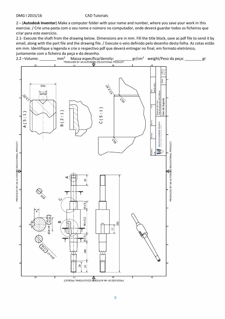
2 – (Autodesk Inventor) Make a computer folder with your name and number, where you save your work in this exercise. / Crie uma pasta com o seu nome e número no computador, onde deverá guardar todos os ficheiros que criar para este exercício. 2.1- Execute the shaft from the drawing below. Dimensions are in mm. Fill the title block, save as pdf file to send it by email, along with the part file and the drawing file. / Execute o veio definido pelo desenho desta folha. As cotas estão em mm. Identifique a legenda e crie o respectivo pdf que deverá entregar no final, em formato eletrónico, juntamente com o ficheiro da peça e do desenho. 2.2 –Volume: ________ mm3 MMassa específica/density: ________ gr/cm3 weight/Peso da peça: ________ gr

DMG I 2015/16 CAD Tutorials
10
Create a new part based on “Standard mm” template
Create a new sketch for the shaft profile (XY plane in this example). Draw a rough sketch of the longitudinal section of the shaft. Dimension it without changing the values (this avoid some cases where the sketch “twist”, see below). Next change every dimension to to correct one. / Crie um novo sketch com o perfil longitudinal do veio. Desenho um esboço e cote-o aceitando os valores propostos (assim evita que o sketch possa ser “torcido”, veja o exemplo abaixo). De seguida altere as cotas para os valores corretos.

DMG I 2015/16 CAD Tutorials
11
In “3D Model”, Revolve the sketch. No separador “3D Model” faça o “Revolve” do Sketch.
To create the slot (for a keyway), first select the pointed face for the sketch plane./Para criar o escatél (para uma chaveta), inicialmente selecione a face indicada para o plano do sketch.
Draw the sketch. / Desenhe o sketch.

DMG I 2015/16 CAD Tutorials
12
Make the extrude cut. / Faça o corte de material.
Make the R=3mm fillet. Click on the indicated edges. / Faça o fillet de R=3mm. Clique sobre a aresta indicada. Save the work. / Grave o trabalho.

DMG I 2015/16 CAD Tutorials
13
Create the Thread. Click on the cilindrical face, close to the end of the shaft. Repeat on the other side of the shaft. / Faça a rosca na ponta do veio. Clique na face cilindrica perto da ponta do veio. Repita para a outra ponta do veio.
Make the 2 chamfers on both ends. / Faça os 2 chamfros nas pontas do veio.
Create the conical hole at the end of the shaft (see detail A on the drawing). Use the common Extrude cut feature with a taper angle of -45 degrees./ Crie o furo cónico na ponta do veio (ver o detalhe A no desenho). Use o extrude em corte com um ângulo de saída de -45 graus.
DMG I 2015/16 CAD Tutorials
14
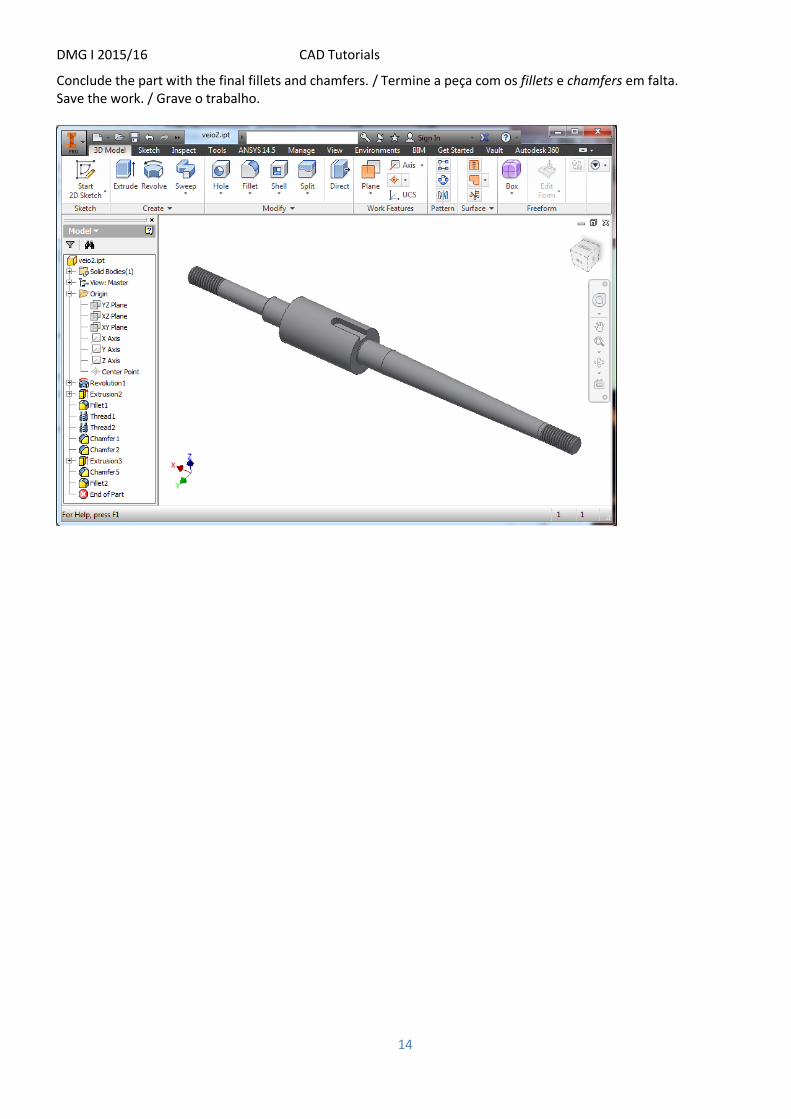
Conclude the part with the final fillets and chamfers. / Termine a peça com os fillets e chamfers em falta. Save the work. / Grave o trabalho.

DMG I 2015/16 CAD Tutorials
15
3 – Create the part below, and assemble it with the previous shaft, as depicted on the right side of the image. / Crie a peça abaixo e faça o assembly com o veio do exercício 2, conforme a imagem à direita.
Create a new assembly based on “Standard mm”./ Crie um novo Assembly, baseado no “Standard mm”

DMG I 2015/16 CAD Tutorials
16
Insert the shaft on it. / Insira o veio do exercício anterior no assembly.
Create the new part (drum). Ensure the use of Standard mm template. /Crie uma nova peça (o tambor). De forma a garantir a utilização do template Standard mm use o botão indicado.
Click on selected face. / Clique sobre a face indicada do veio.

DMG I 2015/16 CAD Tutorials
17
Create the sketch on the longitudinal plane (ensure it is a plane of symmetry), in the example the YZ plane. /Crie um sketch no plano longitudinal do veio (assegure-se que é um plano de simetria!), neste exemplo o plano YZ do tambor.
Create a rough sketch close to the drum section. Dimension it, accepting the proposed dimensions. Next, change the dimension values to the correct ones. /Crie o sketch grosseiro com a forma aproximada à da secção do tambor. Cote o sketch, aceitando as medidas propostas. De seguida reponha os valores corretos das cotas.
Use Dimension tool and Constraints (equal length “=”) for pointed lines. / Use a ferramenta de cotagem (“Dimension”), bem como o constrangimento de igual comprimento (“=”) para os dois segmentos indicados.

DMG I 2015/16 CAD Tutorials
18
Use feature “Revolve” from “3D Model” tab. /No separador “3D Model”, use a operação “Revolve”.
Open the Drum as a separate file for easy complete. /Abra a peça Tambor em separado, para a poder editar e completar mais facilmente. Create the sketch on the circular face (ensure concentricity between circles φ26 and φ80). Do the needed trims. /Na face circular, crie o sketch indicado (garanta concentricidade entre o φ26 e o φ80). Faça os “Trim” convenientes.

DMG I 2015/16 CAD Tutorials
19
Insert the assembly constraints between both parts to obtain the result. / No assembly faça as relações convenientes entre ambas as peças, de forma a obter o resultado: