DLS-6 DLS-18 DLS-18 Loop-through outputs The loop-through outputs of the DLS-6 are located directly...
111
Operating manual DLS-6 DLS-18 No.: DK 180.002.000 GB / HBV 3.1 / 000606
Transcript of DLS-6 DLS-18 DLS-18 Loop-through outputs The loop-through outputs of the DLS-6 are located directly...
1Dallmeier electronic GmbH
Operating manual
DLS-6DLS-18
No.: DK 180.002.000 GB / HBV 3.1 / 000606
2
DLS-6 and -18
Dallmeier electronic GmbH
Copyright © Dallmeier electronic Videocontrollsysteme GmbH
All rights reserved. No part of this document may be copied,photocopied, reproduced, translated, transferred onto anelectronic medium or brought into machine readable formwithout the prior written consent of Dallmeier electronicVideocontrollsysteme GmbH.
Subject to technical amendment.
Dallmeier electronic GmbHWürzburger Str. 5D 93059 Regensburg
3Dallmeier electronic GmbH
Contents
Contents
Contents ................................................................................. 3Introduction .............................................................................. 6Safety Instructions .................................................................... 7
Installation and Configuration instructionsfor the Installer and administrator
DLS Connection Panel ........................................................... 15Description of the LED’s ................................................. 16
First Operation ....................................................................... 17Password ............................................................................... 19
Main Menu ............................................................................. 20Direct selection of a camera .......................................... 20Transfer of a picture via sequencer ............................... 20Activating the playback menu ........................................ 20Import of stored pictures ................................................ 21Setup .............................................................................. 21Downloading the Wavelet Converter ............................. 21Switching off the system................................................. 21
Setup Menus .......................................................................... 22Configuring the sequencer ............................................. 23
Defining cameras for the sequencer ...................... 23Deleting cameras from the Display Sequence ....... 24Disabling cameras for the Display Sequence ........ 24Switchover frequency ............................................. 25Activating event controlled display......................... 25
Operator Texts (Camera Texts) .............................................. 27
Camera Settings .................................................................... 29Camera Settings (Submenu) .......................................... 31
Recording mode ..................................................... 31Motion detection / Sensitivity ................................. 31
4
DLS-6 and -18
Dallmeier electronic GmbH
Recording interval - Normal operation ................... 34Recording interval - Alarm ..................................... 34Resolution - Normal / Resolution - Alarm............. 34
Menu „Options“ ...................................................................... 35Camera synchronisation ................................................ 35Alarm duration ................................................................ 35Main password test ........................................................ 36Keyboard Mode .............................................................. 36Camera failure check ..................................................... 36Monitor output 2 ............................................................. 36Motion detection display ................................................ 37
Track configuration................................................................. 39Levels of Compression................................................... 41Memory capacity utilization ............................................ 44
Configuration of areas ............................................................ 45Picture areas inactive..................................................... 45Picture area active ......................................................... 46
Setting the week timer ............................................................ 49Defining inactive time periods ........................................ 49Defining active time periods ........................................... 51
Menu „Service“ ....................................................................... 53Parameter – Export ........................................................ 53Parameter – Import ........................................................ 53Parameter - Default ........................................................ 54Software - Update .......................................................... 54Extensions - Code .......................................................... 54Network - Import ............................................................. 55Network - Export ............................................................ 55Network - Setup ............................................................. 55
Ethernet / Tokenring ............................................... 56ISDN ...................................................................... 57Devicename ........................................................... 58Alarm Hosts............................................................ 59
5Dallmeier electronic GmbH
Changing the password ......................................................... 63
Changing the menu language ................................................ 65
Info Menu ............................................................................... 66
Start recording ....................................................................... 67
Operating and Configuration instructions for the Operator
Playback of stored pictures .................................................... 71Playback speed .............................................................. 72Fast picture search ........................................................ 72Camera Filter ................................................................. 73Exporting pictures or picture sequences ........................ 74Exporting single pictures onto diskette .......................... 74Storing picture sequences on video tape ....................... 76Transfer onto external digital media ............................... 79Playing back exported pictures ...................................... 81
Operator Setup ....................................................................... 83Configuring the sequencer ............................................. 85Changing Camera Texts ................................................. 86Setting the timer ............................................................. 87Changing the Operator Password .................................. 89Changing the menu language ........................................ 90Setting date and time ..................................................... 90
Wavelet Converter “PConvert” ............................................... 91Converting Wavelet pictures .......................................... 94
Technical Data and Contact Layout ....................................... 97External Contacts (Contact IN) ...................................... 99Output Contacts (Contact Out) .................................... 100Serial Interfaces (Serial 1 and 2) ................................. 101Technical Data DLS-6 / DLS-18 ................................... 102
Contents

6
DLS-6 and -18
Dallmeier electronic GmbH
The digital longplay recorders DLS 6 and DLS-18offer a state of the art alternative to timelapserecorders.Since the two systems only differ in the number ofinputs available, the operating manual refers to„DLS“ only.
As far as the inputs are concerned it should be notedthat with DLS-6 the video signals can be looped-through. With DLS-18 this is only possible via asupplementary circuit (BNC distributor).
The DLS has one Longplay track. This track can beused for permanent or contact-controlled recordingor for recording with picture comparison.A separate Alarm track is provided for reliablerecording following an alarm signal.
N.B.:
Before using your DLS for the first time, it is veryimportant that you first read the relevant sections ofthis operating manual.Follow the instructions for installation and operationdescribed in this manual exactly!No responsibility can be accepted for incorrectconnection or improper use.For this reason please also observe the safetyinstructions.
Introduction
7Dallmeier electronic GmbH
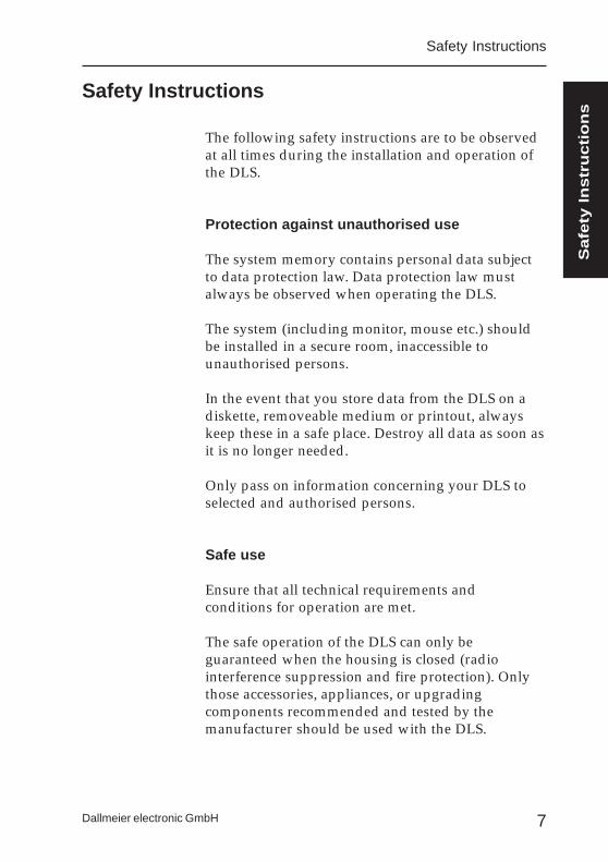
The following safety instructions are to be observedat all times during the installation and operation ofthe DLS.
Protection against unauthorised use
The system memory contains personal data subjectto data protection law. Data protection law mustalways be observed when operating the DLS.
The system (including monitor, mouse etc.) shouldbe installed in a secure room, inaccessible tounauthorised persons.
In the event that you store data from the DLS on adiskette, removeable medium or printout, alwayskeep these in a safe place. Destroy all data as soon asit is no longer needed.
Only pass on information concerning your DLS toselected and authorised persons.
Safe use
Ensure that all technical requirements andconditions for operation are met.
The safe operation of the DLS can only beguaranteed when the housing is closed (radiointerference suppression and fire protection). Onlythose accessories, appliances, or upgradingcomponents recommended and tested by themanufacturer should be used with the DLS.
Safety Instructions
Safety Instructions
Safe
ty I
nstr
uctio
ns
8
DLS-6 and -18
Dallmeier electronic GmbH
Target Groups
No specialist technical knowledge is required tooperate the DLS. However you should be proficientin the use of a PC-mouse.The installation, configuration, inspection andrepair of the DLS should only be executed by trainedand authorised specialist staff.
Precautionary Measures
The system and all related appliances comply withthe relevant safety regulations for informationtechnology equipment.
Transport and shipping of the DLS
Always use either the original packing or alternativeother suitable packing for the transport of the DLSand any additional components. The packing mustprovide adequate protection against transportdamage and weather.
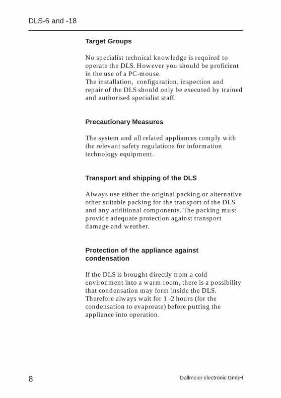
Protection of the appliance againstcondensation
If the DLS is brought directly from a coldenvironment into a warm room, there is a possibilitythat condensation may form inside the DLS.Therefore always wait for 1 -2 hours (for thecondensation to evaporate) before putting theappliance into operation.

9Dallmeier electronic GmbH
Environment
It is important that the DLS is installed in a suitableenvironment. If the main unit is mounted in acupboard always ensure that the DLS is adequatelyventilated. During operation the surroundingtemperature should not exceed 35°C. Ventilationgrills should be kept free at all times.
Mains Voltage
Check the mains voltage at the installation site. Themains voltage must be correspond with that of theDLS and any additional components. Under nocircumstances should the DLS or any of the systemcomponents be operated on any other voltage thanthe specified rated voltage.
Mains Cable / Mains Adapter
All system components are supplied complete withan approved mains cable and mains adapter. Theappliances should only be connected to earthedsafety sockets. Wherever possible the DLS should beoperated on an interruption-free (backup) powersupply.
Safety Socket
The safety sockets used to connect the appliancemust be easily accessible at all times.
Safety Instructions
Safe
ty I
nstr
uctio
ns

10
DLS-6 and -18
Dallmeier electronic GmbH
Data transmission or video cables should neverbe connected during electrical storms
Under no circumstances should data transmissionand video connections be either connected ordisconnected during electrical storms.
The appliances should not be moved inoperation
In order to avoid malfunction or defects, the DLSshould never be moved whilst in operation. Beforemoving the DLS the system should always “shutdown” and the appliance switched off.
Avoid getting objects or liquids inside theappliance
Do not allow any objects or liquids to get inside theappliance as these may cause serious damage e.g.short circuit.
What to do if the appliance has been damaged
If an appliance has been damaged, you can smellburning or see smoke, switch off the applianceimmediately and disconnect at the mains (pull outthe plug). Contact your service partner.
11Dallmeier electronic GmbH
Only allow inspections, configuration andrepairs to be conducted by authorised servicepersonnel
Inspections, configuration and repairs to the interiorof the DLS should only be conducted by trained andauthorised service personnel. Before opening thehousing always disconnect the appliance from themains power supply.
Do not touch any components inside theappliance
Touching any components inside the appliance isdangerous and can result in damage to the system orendanger your own safety. Always ensure that theappliance is disconnected from the mains powersupply and follow the electrostatic safety measuresbefore touching any of the interior components.
Instructions for the installation of upgradingcomponents
Any upgrading components must comply with theregulations and specifications for safety,electromagnetic compatibility andtelecommunication appliances. The use of unsuitableupgrading components may result in either aviolation of the regulations or damage to the system.Always check first with your service partner if youhave any queries concerning the suitability ofupgrading components.
Safety Instructions
Safe
ty I
nstr
uctio
ns

12
DLS-6 and -18
Dallmeier electronic GmbH
13Dallmeier electronic GmbH
Installation andConfiguration instructions
for the Installer andadministrator
This section of the operating manual contains fullycomprehensive instructions for the installation andconfiguration of the system.This section can be left out by any „Operator“ notwishing to make any changes to a system which hasalready been configured.
Adm
inis
trato
r S
etu
p
14
DLS-6 and -18
Dallmeier electronic GmbH
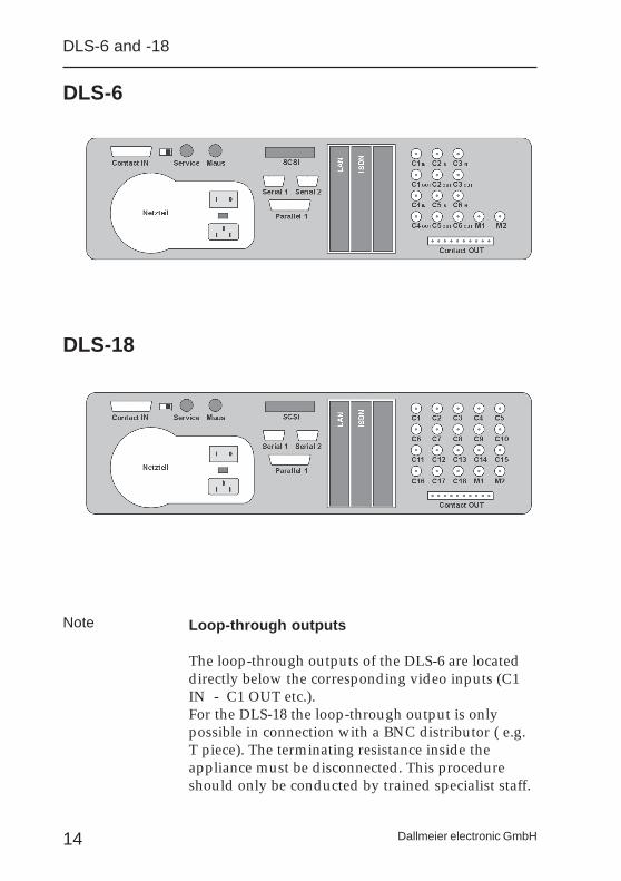
DLS-6
DLS-18
Loop-through outputs
The loop-through outputs of the DLS-6 are locateddirectly below the corresponding video inputs (C1IN - C1 OUT etc.).For the DLS-18 the loop-through output is onlypossible in connection with a BNC distributor ( e.g.T piece). The terminating resistance inside theappliance must be disconnected. This procedureshould only be conducted by trained specialist staff.
Note
15Dallmeier electronic GmbH
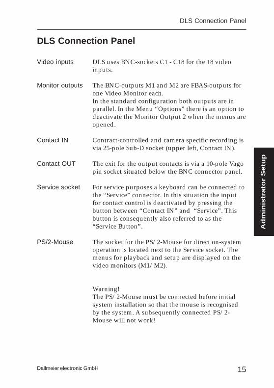
DLS Connection Panel
DLS uses BNC-sockets C1 - C18 for the 18 videoinputs.
The BNC-outputs M1 and M2 are FBAS-outputs forone Video Monitor each.In the standard configuration both outputs are inparallel. In the Menu “Options” there is an option todeactivate the Monitor Output 2 when the menus areopened.
Contract-controlled and camera specific recording isvia 25-pole Sub-D socket (upper left, Contact IN).
The exit for the output contacts is via a 10-pole Vagopin socket situated below the BNC connector panel.
For service purposes a keyboard can be connected tothe “Service” connector. In this situation the inputfor contact control is deactivated by pressing thebutton between “Contact IN” and “Service”. Thisbutton is consequently also referred to as the“Service Button”.
The socket for the PS/2-Mouse for direct on-systemoperation is located next to the Service socket. Themenus for playback and setup are displayed on thevideo monitors (M1/M2).
Warning!The PS/2-Mouse must be connected before initialsystem installation so that the mouse is recognisedby the system. A subsequently connected PS/2-Mouse will not work!
Video inputs
Monitor outputs
Contact IN
Contact OUT
Service socket
PS/2-Mouse
DLS Connection Panel
Adm
inis
trato
r S
etu
p
16
DLS-6 and -18
Dallmeier electronic GmbH
Where necessary a data interface DTP 3 can beconnected to the RS-232 input “Serial 1”. The input“Serial 2” can be used for the operation of the DLSvia PC (e.g. Management System). In cases wheredata insertion is not required the input “Serial 1” canalso be used for PC operation.
The SCSI-Port is an optional extra. Via this port it ispossible to connect external SCSI-Hard disks formemory expansion or external drives such as a JAZor MOD-Drive for back-up purposes. The requiredID for an external JAZ-Drive (backup) is ID 2.
There are two free slots for “Network Operation”and “ISDN Operation”. If, in addition to networkoperation, ISDN operation is also required, thesystem can be accessed in both ways.A third slot is available for future extensions/upgrades.
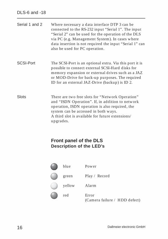
Front panel of the DLSDescription of the LED’s
blue Power
green Play / Record
yellow Alarm
red Error(Camera failure / HDD defect)
Serial 1 and 2
SCSI-Port
Slots

17Dallmeier electronic GmbH
First Operation
The following instructions should be followingbefore putting the DLS into operation for the firsttime:
a) Check the mains power setting. The switch islocated on the rear cabinet of the system betweenthe power on/off switch and the mainsconnection.
b) Next connect all the cameras to thecorresponding inputs - C1 to C6 for DLS-6 andC1 to C18 for DLS-18. The camera input C1 mustbe occupied.
c) Connect the video monitor to the video outputM1. A second monitor can be connected to thevideo output M2.
d) Ensure that the PS/2 mouse is connected beforethe system is switched on. A subsequentlyconnected mouse (once the system has beenswitched on) will not be recognised by thesystem and it will not be possible to operate thesystem.
Once all the components have been connectedcorrectly the system can be turned on. Afterswitching on wait until the system has contactedeach video input, after which the picture fromCamera 1 will appear on the monitor (approx. 120sec.).
First Operation
Adm
inis
trato
r S
etu
p
18
DLS-6 and -18
Dallmeier electronic GmbH
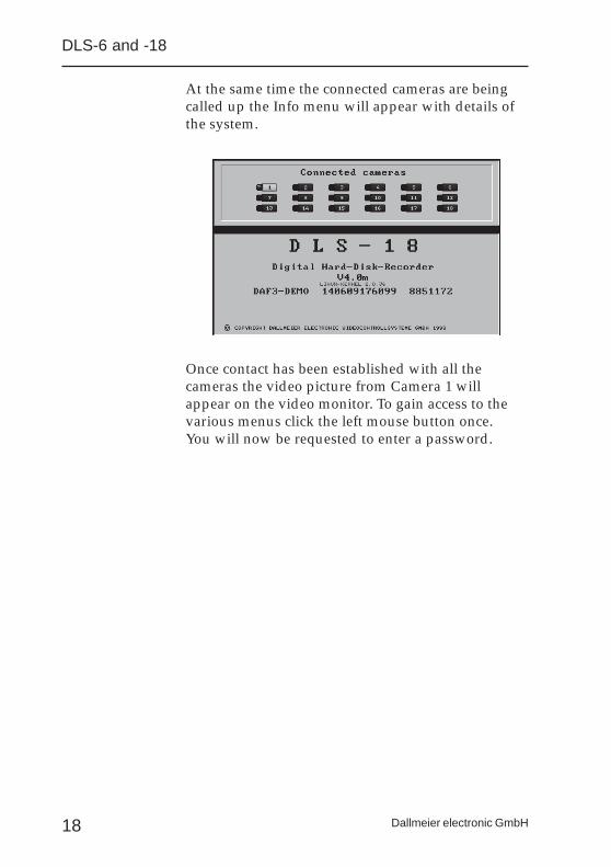
At the same time the connected cameras are beingcalled up the Info menu will appear with details ofthe system.
Once contact has been established with all thecameras the video picture from Camera 1 willappear on the video monitor. To gain access to thevarious menus click the left mouse button once.You will now be requested to enter a password.
19Dallmeier electronic GmbH
Password
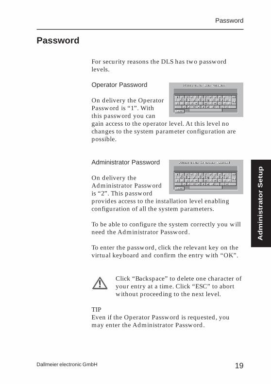
For security reasons the DLS has two passwordlevels.
Operator Password
On delivery the OperatorPassword is “1”. Withthis password you cangain access to the operator level. At this level nochanges to the system parameter configuration arepossible.
Administrator Password
On delivery theAdministrator Passwordis “2”. This passwordprovides access to the installation level enablingconfiguration of all the system parameters.
To be able to configure the system correctly you willneed the Administrator Password.
To enter the password, click the relevant key on thevirtual keyboard and confirm the entry with “OK”.
Click “Backspace” to delete one character ofyour entry at a time. Click “ESC” to abortwithout proceeding to the next level.
TIPEven if the Operator Password is requested, youmay enter the Administrator Password.
Password
Adm
inis
trato
r S
etu
p
20
DLS-6 and -18
Dallmeier electronic GmbH
Main Menu
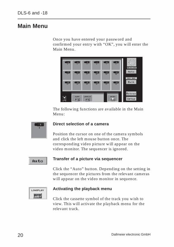
Once you have entered your password andconfirmed your entry with “OK”, you will enter theMain Menu.
The following functions are available in the MainMenu:
Direct selection of a camera
Position the cursor on one of the camera symbolsand click the left mouse button once. Thecorresponding video picture will appear on thevideo monitor. The sequencer is ignored.
Transfer of a picture via sequencer
Click the “Auto” button. Depending on the setting inthe sequencer the pictures from the relevant cameraswill appear on the video monitor in sequence.
Activating the playback menu
Click the cassette symbol of the track you wish toview. This will activate the playback menu for therelevant track.

21Dallmeier electronic GmbH
Import of stored pictures
If pictures have already been stored on a diskette orJAZ-drive, via the import function these pictures canbe viewed on the monitor again.
Setup
Clicking the “SETUP” button will activate the menusfor configuration of all system parameters.Depending on the password used you will eithergain access to the Operator or Administrator Setup.
Downloading the Wavelet Converter
For the purpose of observing and editing storedvideo pictures with standard programmes, thebutton “Extras” includes an option to download apicture conversion programme. This programmeconverts pictures from Wavelet to Bitmap format.
Switching off the system
In the past the DLS could be switched off via thePower On/Off button. The new system operateswith LINUX and no longer with DOS. Beforepressing the Power On/Off button the on-screenbutton “Exit” should be clicked. This ensures thatthe operating system of the DLS is properly shutdown.If the system is not shut down correctly a file checkwill be completed the next time the system is startedup. Booting takes longer.
To ensure that the system can only be shut down byauthorised personnel, the system requests apassword after the “Exit” button has been clicked.
Main Menu
Adm
inis
trato
r S
etu
p
22
DLS-6 and -18
Dallmeier electronic GmbH
Setup Menus
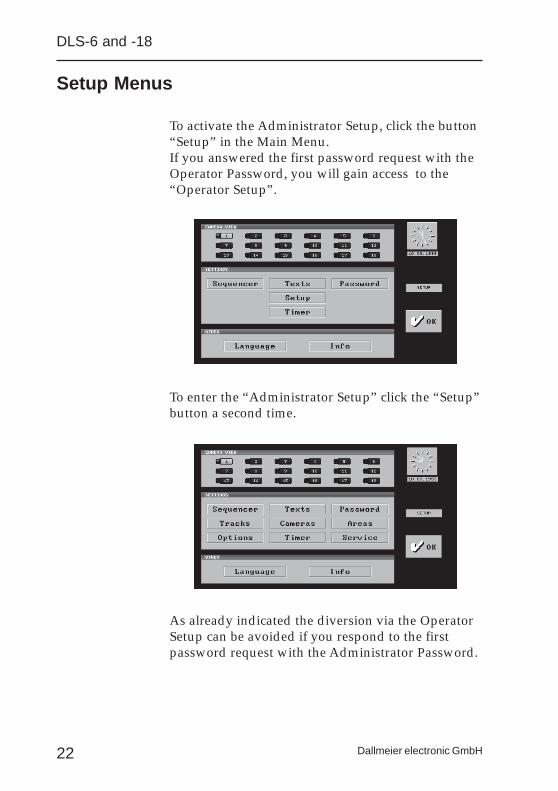
To activate the Administrator Setup, click the button“Setup” in the Main Menu.If you answered the first password request with theOperator Password, you will gain access to the“Operator Setup”.
To enter the “Administrator Setup” click the “Setup”button a second time.
As already indicated the diversion via the OperatorSetup can be avoided if you respond to the firstpassword request with the Administrator Password.
23Dallmeier electronic GmbH
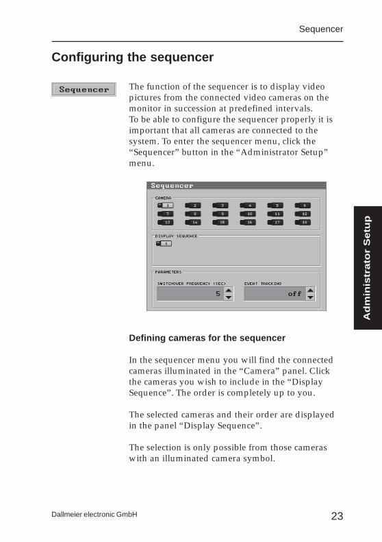
The function of the sequencer is to display videopictures from the connected video cameras on themonitor in succession at predefined intervals.To be able to configure the sequencer properly it isimportant that all cameras are connected to thesystem. To enter the sequencer menu, click the“Sequencer” button in the “Administrator Setup”menu.
Defining cameras for the sequencer
In the sequencer menu you will find the connectedcameras illuminated in the “Camera” panel. Clickthe cameras you wish to include in the “DisplaySequence”. The order is completely up to you.
The selected cameras and their order are displayedin the panel “Display Sequence”.
The selection is only possible from those cameraswith an illuminated camera symbol.
Configuring the sequencer
Sequencer
Adm
inis
trato
r S
etu
p
24
DLS-6 and -18
Dallmeier electronic GmbH
Deleting cameras from the Display Sequence
To delete a camera from the sequence simply clickthe relevant camera symbol in the “DisplaySequence” panel.
If there are no camera symbols displayed in“Display Sequence” panel, the sequencer isautomatically deactivated.
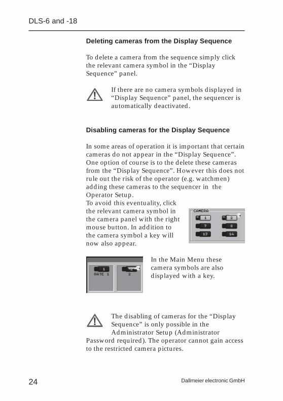
Disabling cameras for the Display Sequence
In some areas of operation it is important that certaincameras do not appear in the “Display Sequence”.One option of course is to the delete these camerasfrom the “Display Sequence”. However this does notrule out the risk of the operator (e.g. watchmen)adding these cameras to the sequencer in theOperator Setup.To avoid this eventuality, clickthe relevant camera symbol inthe camera panel with the rightmouse button. In addition tothe camera symbol a key willnow also appear.
In the Main Menu thesecamera symbols are alsodisplayed with a key.
The disabling of cameras for the “DisplaySequence” is only possible in theAdministrator Setup (Administrator
Password required). The operator cannot gain accessto the restricted camera pictures.
25Dallmeier electronic GmbH
Switchover frequency
The setting “switchover frequency (sec.)” defines theinterval in which the video pictures are switchedfrom camera to camera. The value should not be lessthan 5 seconds, otherwise it is extremely difficult toevaluate the picture.
The setting applies for all the cameras in the“Display Sequence”. However some video picturesmay require longer observation, in which case:
When selecting the cameras for the “DisplaySequence”, click the relevant camera symbol twice(or more) in succession. The picture will now appeartwice in the “Display Sequence”. With a switchoverfrequency of 5 seconds for example, the picture inquestion will now be displayed on the monitor for10 seconds.
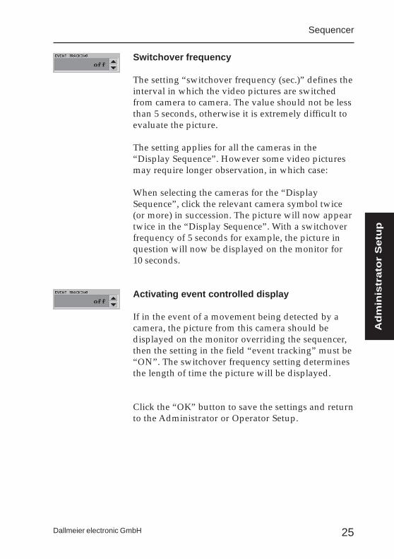
Activating event controlled display
If in the event of a movement being detected by acamera, the picture from this camera should bedisplayed on the monitor overriding the sequencer,then the setting in the field “event tracking” must be“ON”. The switchover frequency setting determinesthe length of time the picture will be displayed.
Click the “OK” button to save the settings and returnto the Administrator or Operator Setup.
Sequencer
Adm
inis
trato
r S
etu
p

26
DLS-6 and -18
Dallmeier electronic GmbH
27Dallmeier electronic GmbH
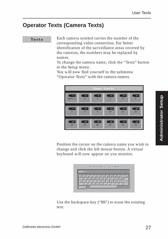
Each camera symbol carries the number of thecorresponding video connection. For betteridentification of the surveillance areas covered bythe cameras, the numbers may be replaced bynames.To change the camera name, click the “Texts” buttonin the Setup menu.You will now find yourself in the submenu“Operator Texts” with the camera names.
Position the cursor on the camera name you wish tochange and click the left mouse button. A virtualkeyboard will now appear on you monitor.
Use the backspace key (“BS”) to erase the existingtext.
Operator Texts (Camera Texts)
User Texts
Adm
inis
trato
r S
etu
p
28
DLS-6 and -18
Dallmeier electronic GmbH
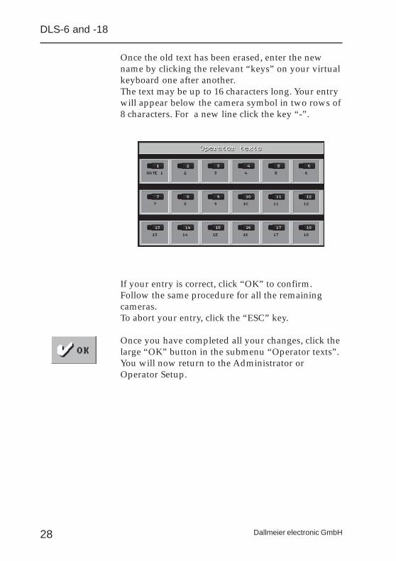
Once the old text has been erased, enter the newname by clicking the relevant “keys” on your virtualkeyboard one after another.The text may be up to 16 characters long. Your entrywill appear below the camera symbol in two rows of8 characters. For a new line click the key “-”.
If your entry is correct, click “OK” to confirm.Follow the same procedure for all the remainingcameras.To abort your entry, click the “ESC” key.
Once you have completed all your changes, click thelarge “OK” button in the submenu “Operator texts”.You will now return to the Administrator orOperator Setup.
29Dallmeier electronic GmbH
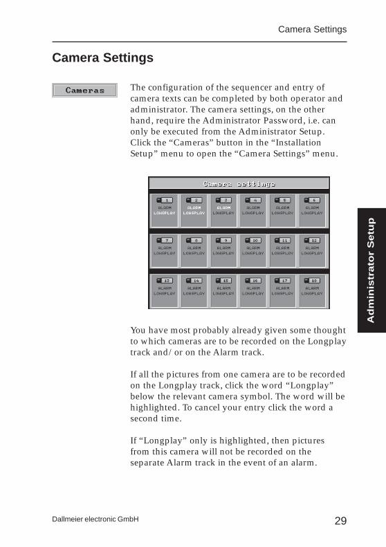
The configuration of the sequencer and entry ofcamera texts can be completed by both operator andadministrator. The camera settings, on the otherhand, require the Administrator Password, i.e. canonly be executed from the Administrator Setup.Click the “Cameras” button in the “InstallationSetup” menu to open the “Camera Settings” menu.
You have most probably already given some thoughtto which cameras are to be recorded on the Longplaytrack and/or on the Alarm track.
If all the pictures from one camera are to be recordedon the Longplay track, click the word “Longplay”below the relevant camera symbol. The word will behighlighted. To cancel your entry click the word asecond time.
If “Longplay” only is highlighted, then picturesfrom this camera will not be recorded on theseparate Alarm track in the event of an alarm.
Camera Settings
Camera Settings
Adm
inis
trato
r S
etu
p
30
DLS-6 and -18
Dallmeier electronic GmbH
If you click the word “Alarm Track” the picturesfrom these cameras will be recorded on a separateAlarm track in the event of an alarm contact.
As opposed to the Longplay track, theAlarm track is not a ring memory. Once theAlarm track is full or the alarm period isover recording on the Alarm track will end.The pictures cannot be overwritten.
A new alarm can only be recorded after the Alarmtrack has been re-enabled (erase track).However this should not be done before the firstalarm recording has been analysed.
Once you have decided on which track the camerapictures are to be recorded, the “fine tuning” for therecording is done in a submenu.
To open the submenu, position the cursor onthe relevant track name in the “CameraSettings” menu and click the right mousebutton.
31Dallmeier electronic GmbH
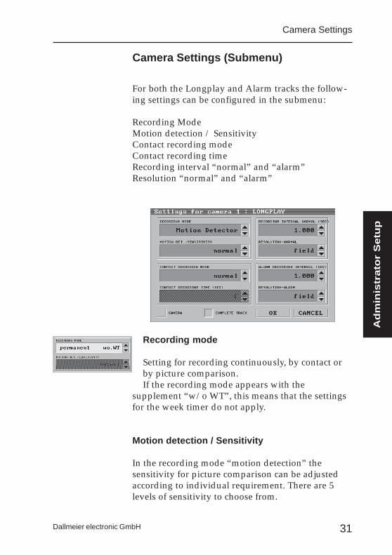
Recording mode
Setting for recording continuously, by contact orby picture comparison.If the recording mode appears with the
supplement “w/o WT”, this means that the settingsfor the week timer do not apply.
Motion detection / Sensitivity
In the recording mode “motion detection” thesensitivity for picture comparison can be adjustedaccording to individual requirement. There are 5levels of sensitivity to choose from.
For both the Longplay and Alarm tracks the follow-ing settings can be configured in the submenu:
Recording ModeMotion detection / SensitivityContact recording modeContact recording timeRecording interval “normal” and “alarm”Resolution “normal” and “alarm”
Camera Settings (Submenu)
Camera Settings
Adm
inis
trato
r S
etu
p
32
DLS-6 and -18
Dallmeier electronic GmbH
normal
toggle
start
timer
Mode Recording interval Contact recording time PcturesNormal operation per Contact
timer 0,200 sec. 4 sec. 20= 5 pictures / sec.
timer 0,500 sec. 3 sec. 6= 2 pictures / sec.
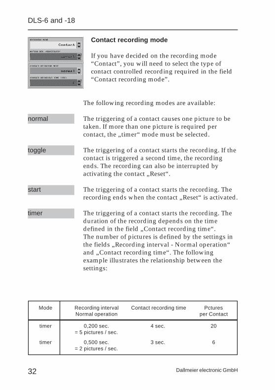
Contact recording mode
If you have decided on the recording mode“Contact”, you will need to select the type ofcontact controlled recording required in the field“Contact recording mode”.
The following recording modes are available:
The triggering of a contact causes one picture to betaken. If more than one picture is required percontact, the „timer“ mode must be selected.
The triggering of a contact starts the recording. If thecontact is triggered a second time, the recordingends. The recording can also be interrupted byactivating the contact „Reset“.
The triggering of a contact starts the recording. Therecording ends when the contact „Reset“ is activated.
The triggering of a contact starts the recording. Theduration of the recording depends on the timedefined in the field „Contact recording time“.The number of pictures is defined by the settings inthe fields „Recording interval - Normal operation“and „Contact recording time“. The followingexample illustrates the relationship between thesettings:
33Dallmeier electronic GmbH
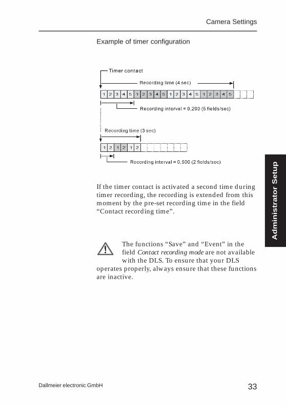
Example of timer configuration
If the timer contact is activated a second time duringtimer recording, the recording is extended from thismoment by the pre-set recording time in the field“Contact recording time”.
The functions “Save” and “Event” in thefield Contact recording mode are not availablewith the DLS. To ensure that your DLS
operates properly, always ensure that these functionsare inactive.
Camera Settings
Adm
inis
trato
r S
etu
p
34
DLS-6 and -18
Dallmeier electronic GmbH
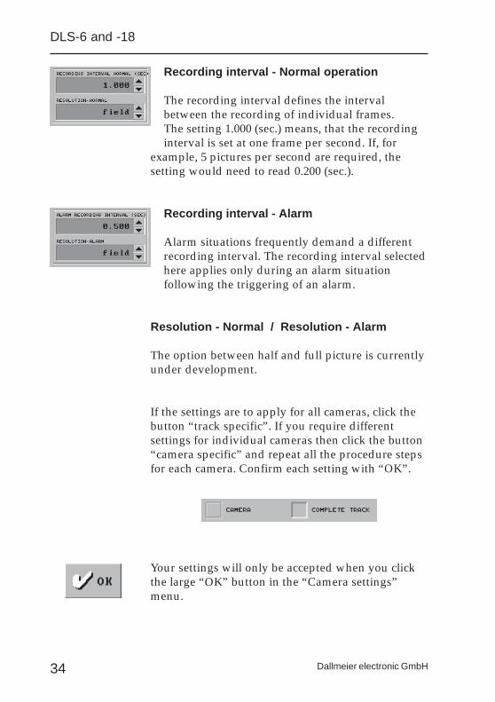
Recording interval - Normal operation
The recording interval defines the intervalbetween the recording of individual frames.The setting 1.000 (sec.) means, that the recordinginterval is set at one frame per second. If, for
example, 5 pictures per second are required, thesetting would need to read 0.200 (sec.).
Recording interval - Alarm
Alarm situations frequently demand a differentrecording interval. The recording interval selectedhere applies only during an alarm situationfollowing the triggering of an alarm.
Resolution - Normal / Resolution - Alarm
The option between half and full picture is currentlyunder development.
If the settings are to apply for all cameras, click thebutton “track specific”. If you require differentsettings for individual cameras then click the button“camera specific” and repeat all the procedure stepsfor each camera. Confirm each setting with “OK”.
Your settings will only be accepted when you clickthe large “OK” button in the “Camera settings”menu.

35Dallmeier electronic GmbH
To activate the „Options“ menu click the „Options“button in „Administrator Setup“ menu.
Camera synchronisation
This field determines whether the cameras are tobe operated asynchronously or synchronously.
Where “synchronous” operation is selected it doesnot matter whether the cameras are synchronisedwith linelock or genlock. The system adjusts therelevant internal values automatically.
Alarm duration
The pre-set time (sec.) controls the duration of therecording in the event of an alarm. An alarm is
defined as a connection in the global contact“Alarm” (e.g. via “Forceful Entry Detection System”or attack button). The system does not recognisesignals from movement detectors (picturecomparison) or contact-activated camera recordingsas an “Alarm”.
Menu „Options“
Menu „Options“
Adm
inis
trato
r S
etu
p
36
DLS-6 and -18
Dallmeier electronic GmbH
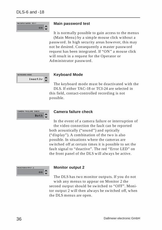
Main password test
It is normally possible to gain access to the menus(Main Menu) by a simple mouse click without a
password. In high security areas however, this maynot be desired. Consequently a master passwordrequest has been integrated. If “ON” a mouse clickwill result in a request for the Operator orAdministrator password.
Keyboard Mode
The keyboard mode must be deactivated with theDLS. If either TAC-18 or TCI-24 are selected in
this field, contact-controlled recording is notpossible.
Camera failure check
In the event of a camera failure or interruption ofthe video connection the fault can be reported
both acoustically (“sound”) and optically(“display”). A combination of the two is alsopossible. In situations where the cameras areswitched off at certain times it is possible to set thefault signal to “deactive”. The red “Error LED” onthe front panel of the DLS will always be active.
Monitor output 2
The DLS has two monitor outputs. If you do notwish any menus to appear on Monitor 2 the
second output should be switched to “OFF”. Moni-tor output 2 will then always be switched off, whenthe DLS menus are open.
37Dallmeier electronic GmbH
Menu „Options“
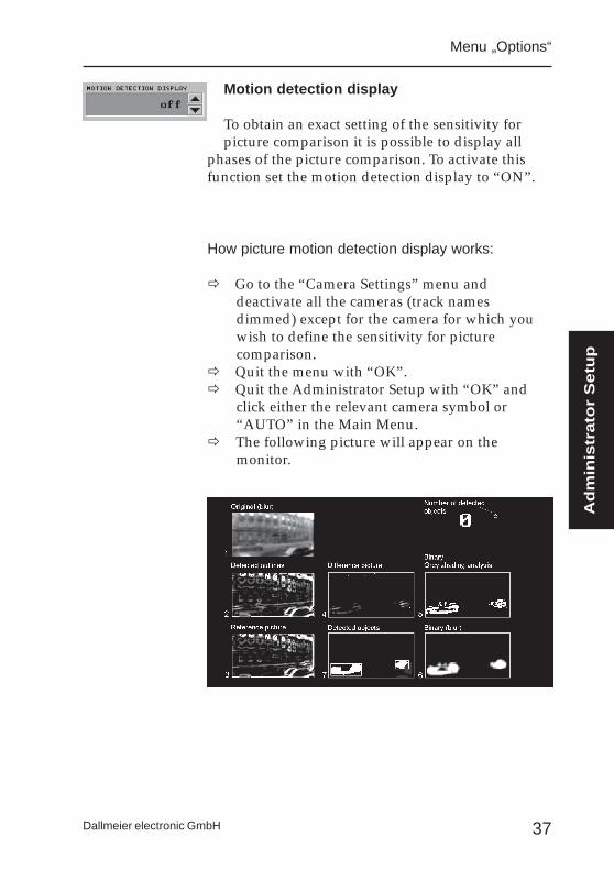
Motion detection display
To obtain an exact setting of the sensitivity forpicture comparison it is possible to display all
phases of the picture comparison. To activate thisfunction set the motion detection display to “ON”.
How picture motion detection display works:
ð Go to the “Camera Settings” menu anddeactivate all the cameras (track namesdimmed) except for the camera for which youwish to define the sensitivity for picturecomparison.
ð Quit the menu with “OK”.ð Quit the Administrator Setup with “OK” and
click either the relevant camera symbol or“AUTO” in the Main Menu.
ð The following picture will appear on themonitor.
Adm
inis
trato
r S
etu
p
38
DLS-6 and -18
Dallmeier electronic GmbH
The meaning of the 7 frames of the picturecomparison display is as follows:
Picture 1 The true original picture is blurred.
Picture 2 The outlines of the original picture arehighlighted.
Picture 3 The reference picture is compared withthe outlined original picture (Picture 2)
Picture 4 This picture shows the differencebetween pictures 2 and 3.
Picture 5 Picture 4 is converted to binary andundergoes a grey shading analysis.
Picture 6 The grey shaded picture is convertedinto binary and blurred.
Picture 7 Picture 7 shows the detected object in aframe at the pre-set level of sensitivity.
The menu in the right corner of the screen alsoshows the number of objects detected. The largefigure is the camera number. 0 indicates camerainput 1, 1 is camera input 2 etc..
During normal recording the motiondetection display must be set to “OFF”.
39Dallmeier electronic GmbH
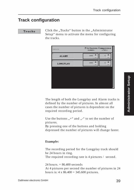
Click the „Tracks“ button in the „AdministratorSetup“ menu to activate the menu for configuringthe tracks.
The length of both the Longplay and Alarm tracks isdefined by the number of pictures. In almost allcases the number of pictures is dependent on therequired recording period.
Use the buttons „+“ and „-“ to set the number ofpictures.By pressing one of the buttons and holdingdepressed the number of pictures will change faster.
Example:
The recording period for the Longplay track shouldbe 24 hours in ring.The required recording rate is 4 pictures / second.
24 hours. = 86.400 secondsAt 4 pictures per second the number of pictures in 24hours is: 4 x 86.400 = 345.600 pictures.
Track configuration
Track configuration
Adm
inis
trato
r S
etu
p
40
DLS-6 and -18
Dallmeier electronic GmbH
When calculating the number of pictures it isimportant to bear in mind whether the cameras aresynchronised via genlock or linelock, or whether thecameras are running asynchronously.
The following picture rates are possible:
Genlock max. 25 pictures per secondLinelock max. 12 pictures per secondAsynchronous max. 12 pictures per second
The calculation of the number of pictures is slightlymore complicated for recording with picturecomparison. In this case a recording is only madewhen some change to the picture has beenidentified. First of all you will need to make a roughestimate of the level of activity on the site. A simpleexample would be the different levels of activityduring the day or at night.
Example:The level of activity during the day is approx. 70%,whereas at night the level falls to approx. 5%.In this example the day has 10 hours.
At 4 pictures per second this would mean:
Day = 10 hrs = 36.000 sec. 144.000 pictures70% = 100.800 pictures
Night = 14 hrs = 50.400 sec. 201.600 pictures 5% = 10.080 pictures
The number of pictures for the Longplay trackwould therefore need to be set at 110.880 pictures.
The number of pictures should always beset somewhat higher than the valuecalculated.
41Dallmeier electronic GmbH
Levels of Compression
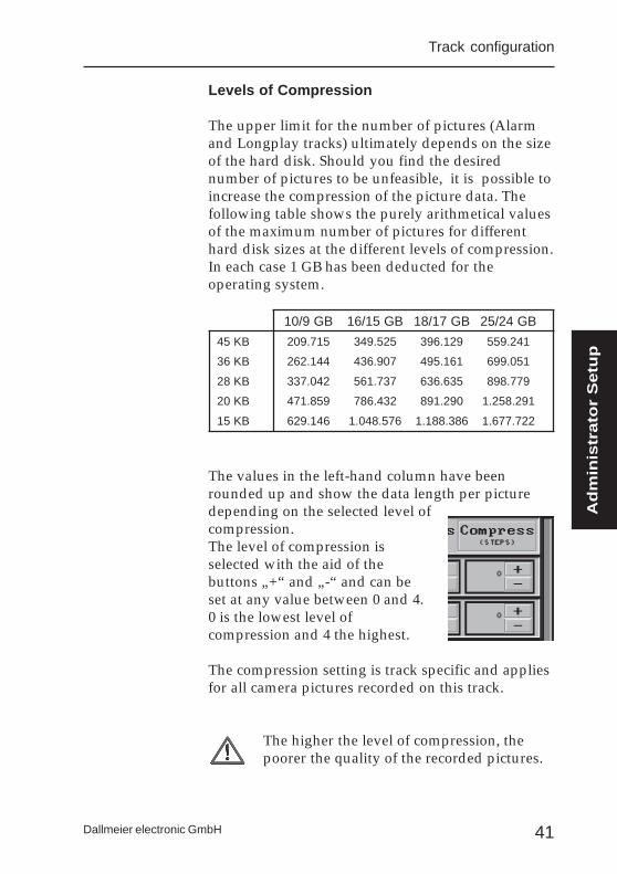
The upper limit for the number of pictures (Alarmand Longplay tracks) ultimately depends on the sizeof the hard disk. Should you find the desirednumber of pictures to be unfeasible, it is possible toincrease the compression of the picture data. Thefollowing table shows the purely arithmetical valuesof the maximum number of pictures for differenthard disk sizes at the different levels of compression.In each case 1 GB has been deducted for theoperating system.
10/9 GB 16/15 GB 18/17 GB 25/24 GB
45 KB 209.715 349.525 396.129 559.241
36 KB 262.144 436.907 495.161 699.051
28 KB 337.042 561.737 636.635 898.779
20 KB 471.859 786.432 891.290 1.258.291
15 KB 629.146 1.048.576 1.188.386 1.677.722
The values in the left-hand column have beenrounded up and show the data length per picturedepending on the selected level ofcompression.The level of compression isselected with the aid of thebuttons „+“ and „-“ and can beset at any value between 0 and 4.0 is the lowest level ofcompression and 4 the highest.
The compression setting is track specific and appliesfor all camera pictures recorded on this track.
The higher the level of compression, thepoorer the quality of the recorded pictures.
Track configuration
Adm
inis
trato
r S
etu
p
42
DLS-6 and -18
Dallmeier electronic GmbH
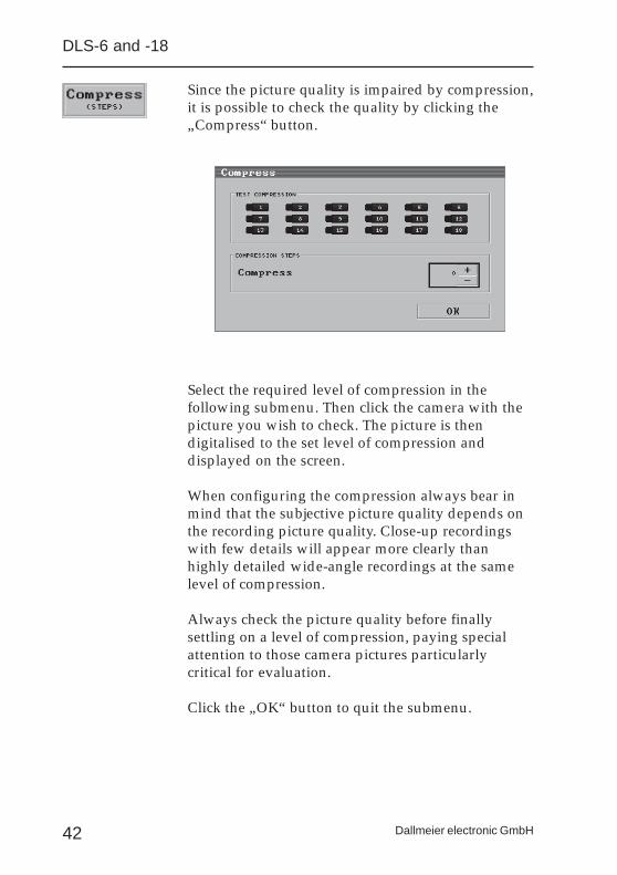
Since the picture quality is impaired by compression,it is possible to check the quality by clicking the„Compress“ button.
Select the required level of compression in thefollowing submenu. Then click the camera with thepicture you wish to check. The picture is thendigitalised to the set level of compression anddisplayed on the screen.
When configuring the compression always bear inmind that the subjective picture quality depends onthe recording picture quality. Close-up recordingswith few details will appear more clearly thanhighly detailed wide-angle recordings at the samelevel of compression.
Always check the picture quality before finallysettling on a level of compression, paying specialattention to those camera pictures particularlycritical for evaluation.
Click the „OK“ button to quit the submenu.

43Dallmeier electronic GmbH
Any settings (number of pictures and level ofcompression) completed in the „Tracks“ menu, willbe accepted by clicking the large „OK“ button in the„Tracks“ menu.
If either the number of pictures or the levelof compression are changed, the system willreorganise the hard disk. Any existingrecorded pictures will be erased during thisprocess.
To ensure that existing recordings are not lost bymistake, a security query appears before the changesare accepted.
The new configuration will only be accepted if thisquery is confirmed with „YES“.
If the changes should not become effective, click„NO“ to return to the „Tracks“ menu. Click „Cancel“to quit this menu without affecting the previousconfiguration.
The track configuration procedures described aboveapply for both Longplay and Alarm tracks. Inpractice the compression levels 1 or 2 are commonlyused for the Longplay track. For the Alarm track 0 ismost frequently used, since evaluation demands ahigh picture quality.
Track configuration
Adm
inis
trato
r S
etu
p

44
DLS-6 and -18
Dallmeier electronic GmbH
Memory capacity utilization
To give you an indication of the total capacityavailable when defining the number of pictures inthe “Tracks” menu, a visual display of the memoryutilization appears in the lower right-hand corner ofthis menu.
The illuminated area of the vertical bar indicates thememory required for the number of pictures set forthe Alarm and Longplay tracks. The dimmed partshows the available memory space. If the number ofpictures is increased, e.g. for the Longplay track, thevisual display is updated automatically.
Low utilization
Nearly maximumutilization
45Dallmeier electronic GmbH
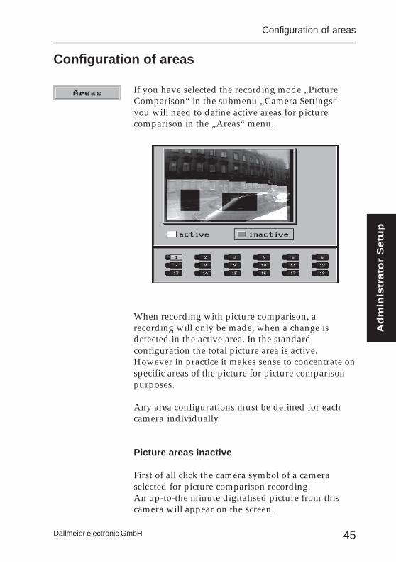
If you have selected the recording mode „PictureComparison“ in the submenu „Camera Settings“you will need to define active areas for picturecomparison in the „Areas“ menu.
When recording with picture comparison, arecording will only be made, when a change isdetected in the active area. In the standardconfiguration the total picture area is active.However in practice it makes sense to concentrate onspecific areas of the picture for picture comparisonpurposes.
Any area configurations must be defined for eachcamera individually.
Picture areas inactive
First of all click the camera symbol of a cameraselected for picture comparison recording.An up-to-the minute digitalised picture from thiscamera will appear on the screen.
Configuration of areas
Configuration of areas
Adm
inis
trato
r S
etu
p

46
DLS-6 and -18
Dallmeier electronic GmbH
Click the grey button for “Inactive”.Position the cursor within the digitalised picture andpress the left mouse button. Hold this key depressedand draw a rectangle by moving the mouse in thedirection required. Once the square has reached therequired size, let go of the left mouse button. Theinactive area is dimmed.
Picture area active
If only smaller areas are to be taken intoconsideration for picture evaluation, we recommendthat the total picture area is “deactivated” first,following the instructions above.Once the total picture area is “inactive”, click thebright button “Active”.You can now define the active areas within thepicture. The procedure is the same as describedabove.
If the selected active area is too small, thewarning “Active area(s) too small. Pleasecorrect.” will appear.
47Dallmeier electronic GmbH
Once you have defined the areas for all the relevantcameras, click the large “OK” button to accept andactivate the configuration.If you do not wish to accept the configuration, click“Cancel”. Only those settings accepted prior toentering the “Areas” menu will go active.
Configuration of areas
Adm
inis
trato
r S
etu
p

48
DLS-6 and -18
Dallmeier electronic GmbH
49Dallmeier electronic GmbH
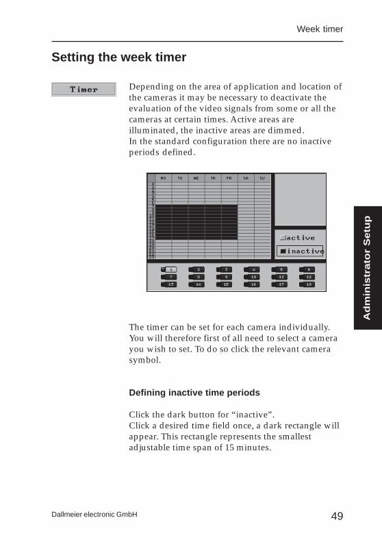
Depending on the area of application and location ofthe cameras it may be necessary to deactivate theevaluation of the video signals from some or all thecameras at certain times. Active areas areilluminated, the inactive areas are dimmed.In the standard configuration there are no inactiveperiods defined.
The timer can be set for each camera individually.You will therefore first of all need to select a camerayou wish to set. To do so click the relevant camerasymbol.
Defining inactive time periods
Click the dark button for “inactive”.Click a desired time field once, a dark rectangle willappear. This rectangle represents the smallestadjustable time span of 15 minutes.
Setting the week timer
Week timer
Adm
inis
trato
r S
etu
p

50
DLS-6 and -18
Dallmeier electronic GmbH
To define a larger time span, position the cursor atthe required starting time. Press the left mousebutton and hold depressed. Now draw the rectangleover the time period during which recording shouldbe inactive.
With this function the smallest adjustable timeinterval is one hour. However it is possible tosubsequently extend or reduce the inactive period in15 minute steps.
For an exact setting position the cursor on the activetime period of the day, during which you wish todefine an inactive time period. Click the right mousebutton once. The area will now appear white and inthe right corner a timer will appear next to the week-by-week calendar. The time period can be increasedor decreased using the “+” / “-” keys.
This adjustment cannot be performed within alreadydefined inactive time periods. It is however possibleto define smaller active periods during inactiveperiods exactly.To do so, click the “Active” panel and then define asmall active field by clicking the left mouse buttononce.
51Dallmeier electronic GmbH
Week timer
The active time span can be adjusted by clicking theright mouse button in the active field and thenproceeding in the same way as described above.
Defining active time periods
The procedure for defining active time periods is thesame as for inactive periods with the exception ofthe exact setting of start and stop times using thetimer panel as described above. It is howeverpossible to click an active area with the right mousebutton and then increase / decrease this area.
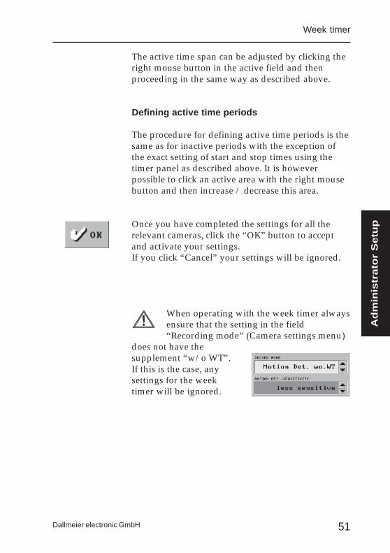
Once you have completed the settings for all therelevant cameras, click the “OK” button to acceptand activate your settings.If you click “Cancel” your settings will be ignored.
When operating with the week timer alwaysensure that the setting in the field“Recording mode” (Camera settings menu)
does not have thesupplement “w/o WT”.If this is the case, anysettings for the weektimer will be ignored.
Adm
inis
trato
r S
etu
p
52
DLS-6 and -18
Dallmeier electronic GmbH
Important notice:
The following section contains instructions forsaving your system configuration on diskette andalso for re-importing the configuration onto thesystem, should this be necessary.
However, parameter configurations from the newsystem DLS cannot be transferred onto systems fromthe “old” generation. A transfer in the oppositedirection, i.e. from older systems onto new systemsis also not possible.
This is due to the fact that the “old” and “new”generations work with different operating systems.
53Dallmeier electronic GmbH
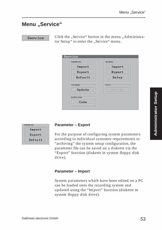
Click the „Service“ button in the menu „Administra-tor Setup“ to enter the „Service“ menu.
Parameter – Export
For the purpose of configuring system parametersaccording to individual customer requirements or“archiving” the system setup configuration, theparameter file can be saved on a diskette via the“Export” function (diskette in system floppy diskdrive).
Parameter – Import
System parameters which have been edited on a PCcan be loaded onto the recording system andupdated using the “Import” function (diskette insystem floppy disk drive).
Menu „Service“
Menu „Service“
Adm
inis
trato
r S
etu
p
54
DLS-6 and -18
Dallmeier electronic GmbH
Parameter - Default
Clicking the button “Default” will cause theparameter file configuration to be reinitialised - i.e.the system configuration will be as on delivery.
Software - Update
Via this function software updates can be loaded asand where required.
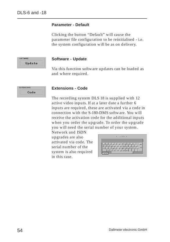
Extensions - Code
The recording system DLS 18 is supplied with 12active video inputs. If at a later date a further 6inputs are required, these are activated via a code inconnection with the S-180-DMS software. You willreceive the activation code for the additional inputswhen you order the upgrade. To order the upgradeyou will need the serial number of your system.Network and ISDNupgrades are alsoactivated via code. Theserial number of thesystem is also requiredin this case.
55Dallmeier electronic GmbH
Menu „Service“ - network
If your DLS is equipped with a network or ISDNcard some adjustments to the Network Setup will benecessary.
Network - Import
In the same way as for the system parameters, thesetup for network configuration of the recordingsystem can be completed on PC and then importedon to the system.
Network - Export
Via the “Export” function the system configurationfor network operation can be saved on a diskette.Data export is also necessary, if the data are to beedited on a PC.
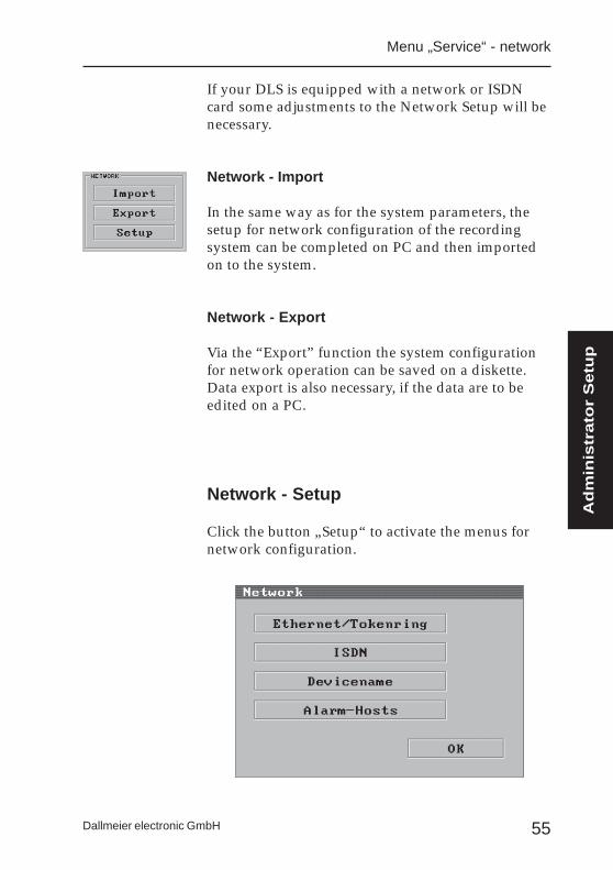
Network - Setup
Click the button „Setup“ to activate the menus fornetwork configuration.
Adm
inis
trato
r S
etu
p
56
DLS-6 and -18
Dallmeier electronic GmbH
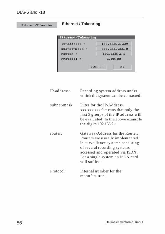
Ethernet / Tokenring
IP-address: Recording system address underwhich the system can be contacted.
subnet-mask: Filter for the IP-Address.xxx.xxx.xxx.0 means that only thefirst 3 groups of the IP address willbe evaluated. In the above examplethe digits 192.168.2.
router: Gateway-Address for the Router.Routers are usually implementedin surveillance systems consistingof several recording systemsaccessed and operated via ISDN.For a single system an ISDN cardwill suffice.
Protocol: Internal number for themanufacturer.
57Dallmeier electronic GmbH
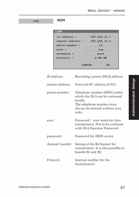
IP-address: Recording system (DLS) address
remote-address: Network-PC address (CPU)
phone-number: Telephone number (MSN) underwhich the DLS can be contactedlocally.The telephone number mustalways be entered without areacode.
user: Password / user name for datatransmission. Not to be confusedwith DLS Operator Password.
password: Password for ISDN access
channel/bundle: Setting of the B-Channel fortransmission. It is also possible tobundle B1 and B2
Protocol: Internal number for themanufacturer
ISDN
Menu „Service“ - network
Adm
inis
trato
r S
etu
p
58
DLS-6 and -18
Dallmeier electronic GmbH
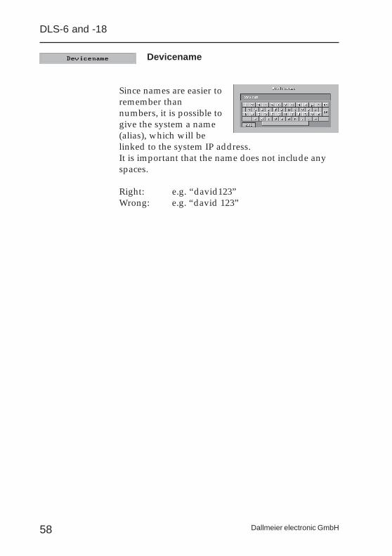
Devicename
Since names are easier toremember thannumbers, it is possible togive the system a name(alias), which will belinked to the system IP address.It is important that the name does not include anyspaces.
Right: e.g. “david123”Wrong: e.g. “david 123”

59Dallmeier electronic GmbH
Alarm-Host
”Alarm-Host” is the name given to the alarmreceiving station (e.g. PView-Station). Use the arrowkeys to switch between the various hosts.To aid the organisation of your system, it is possibleto designate a name for the Alarm-Host.
Name
To change the host-name click the button next to“Name”. Use the virtual keyboard to enter yourname. For example you may wish to name theAlarm-Host “Office”, if the receiving station (PC orPVS) is located in an office.
IP-Address
To ensure that the receiving station (Alarm-Host)can be contacted by the recording system, it isimportant that you enter the correct IP address forthe Alarm-Host (PC or PVS). Click the buttonlocated next to “IP-Address” and key in the IP-Address.
Alarm Hosts
Menu „Service“ - network
Adm
inis
trato
r S
etu
p
60
DLS-6 and -18
Dallmeier electronic GmbH
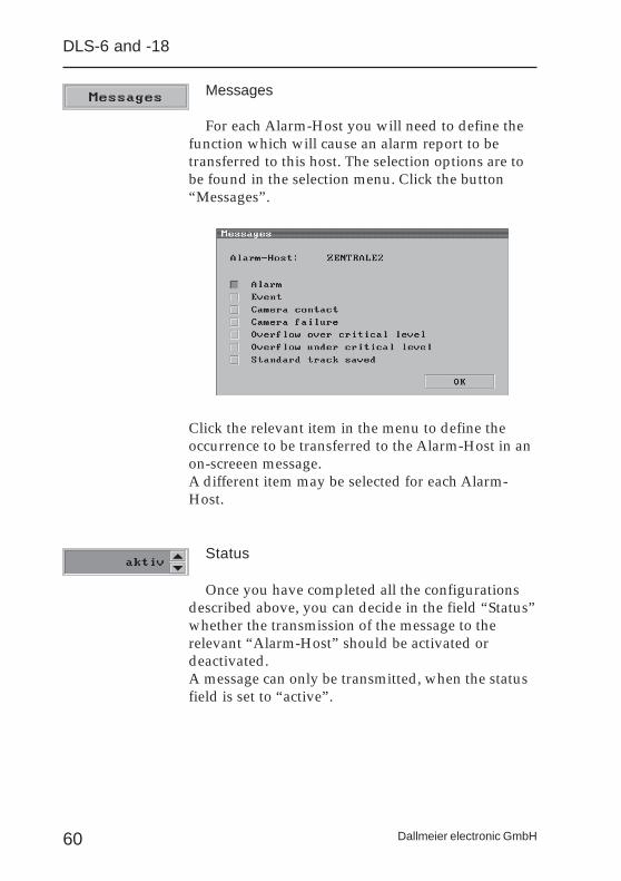
Messages
For each Alarm-Host you will need to define thefunction which will cause an alarm report to betransferred to this host. The selection options are tobe found in the selection menu. Click the button“Messages”.
Click the relevant item in the menu to define theoccurrence to be transferred to the Alarm-Host in anon-screeen message.A different item may be selected for each Alarm-Host.
Status
Once you have completed all the configurationsdescribed above, you can decide in the field “Status”whether the transmission of the message to therelevant “Alarm-Host” should be activated ordeactivated.A message can only be transmitted, when the statusfield is set to “active”.
61Dallmeier electronic GmbH
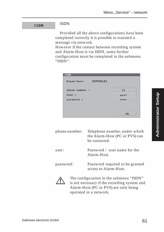
ISDN
Provided all the above configurations have beencompleted correctly it is possible to transmit amessage via network.However if the contact between recording systemand Alarm-Host is via ISDN, some furtherconfiguration must be completed in the submenu“ISDN”.
phone-number: Telephone number, under whichthe Alarm-Host (PC or PVS) canbe contacted.
user: Password / user name for theAlarm-Host.
password: Password required to be grantedaccess to Alarm-Host.
The configuration in the submenu “ISDN”is not necessary if the recording system andAlarm-Host (PC or PVS) are only beingoperated in a network.
Menu „Service“ - network
Adm
inis
trato
r S
etu
p
62
DLS-6 and -18
Dallmeier electronic GmbH
63Dallmeier electronic GmbH
Changing the password
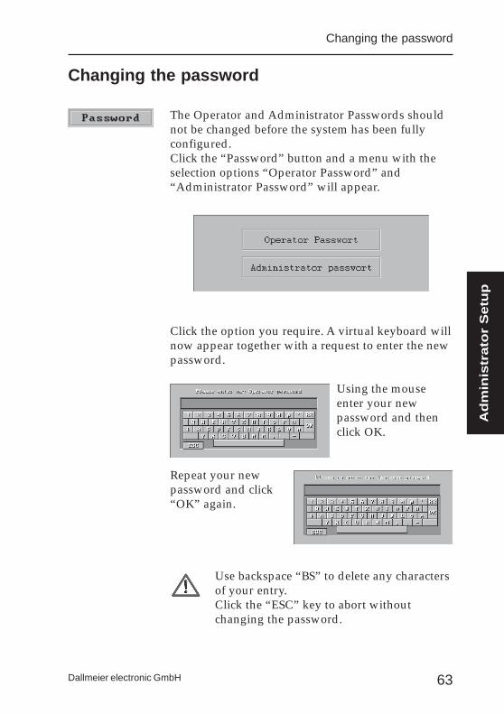
The Operator and Administrator Passwords shouldnot be changed before the system has been fullyconfigured.Click the “Password” button and a menu with theselection options “Operator Password” and“Administrator Password” will appear.
Click the option you require. A virtual keyboard willnow appear together with a request to enter the newpassword.
Using the mouseenter your newpassword and thenclick OK.
Repeat your newpassword and click“OK” again.
Use backspace “BS” to delete any charactersof your entry.Click the “ESC” key to abort withoutchanging the password.
Changing the password
Adm
inis
trato
r S
etu
p
64
DLS-6 and -18
Dallmeier electronic GmbH
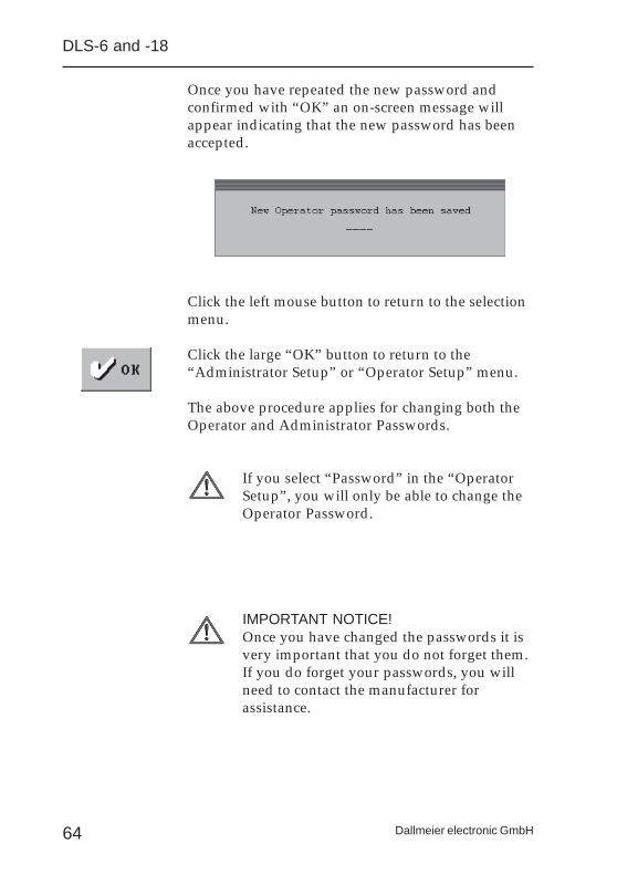
Once you have repeated the new password andconfirmed with “OK” an on-screen message willappear indicating that the new password has beenaccepted.
Click the left mouse button to return to the selectionmenu.
Click the large “OK” button to return to the“Administrator Setup” or “Operator Setup” menu.
The above procedure applies for changing both theOperator and Administrator Passwords.
If you select “Password” in the “OperatorSetup”, you will only be able to change theOperator Password.
IMPORTANT NOTICE!Once you have changed the passwords it isvery important that you do not forget them.If you do forget your passwords, you willneed to contact the manufacturer forassistance.

65Dallmeier electronic GmbH
Changing the menu language
The menus of the DLS can be adapted to thelanguage of the country in which the system is beingoperated.
Click the button „Language“ to change thelanguage.
German and English are the two standardlanguages. French, Italian Spanish and Dutch arealso available on request.
Changing the menu language
Adm
inis
trato
r S
etu
p
66
DLS-6 and -18
Dallmeier electronic GmbH
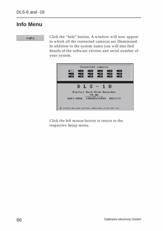
Info Menu
Click the “Info” button. A window will now appearin which all the connected cameras are illuminated.In addition to the system name you will also finddetails of the software version and serial number ofyour system.
Click the left mouse button to return to therespective Setup menu.

67Dallmeier electronic GmbH
Once you have completed the configuration, quit theSetup menu by clicking the large „OK“ button.You are now in the Main Menu.
Recording will not begin until you have quitthe Main Menu.
Before quitting the Main Menu you will need todecide whether the picture from one selected camerais to be transfered to the video monitor or whetherpictures from all the cameras defined in thesequencer are to be transfered to the monitor insequence.
If no entry is made the DLS willautomatically go into sequencer operation„Auto“ once the hour-glass has run out.
Should you wish the video picture from only onecamera to appear on your monitor, click the relevantcamera symbol. If the pictures should appear insequence click the „Auto“ button.
Do not click the „Exit“ button if you wish toswitch to recording mode.
Start recording
Start recording
Adm
inis
trato
r S
etu
p

68
DLS-6 and -18
Dallmeier electronic GmbH

69Dallmeier electronic GmbH
Operating and Configurationinstructions
for the Operator
This section of the operating manual containsinstructions for the operation and configuration of
the system with the Operator Password.
Op
era
tor
Instr
uctio
ns

70
DLS-6 and -18
Dallmeier electronic GmbH
71Dallmeier electronic GmbH
Playback of stored pictures
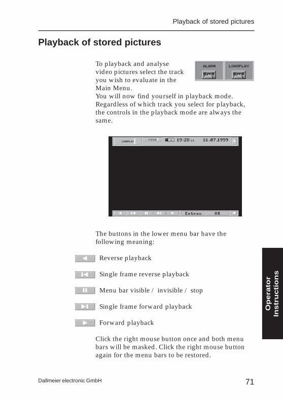
To playback and analysevideo pictures select the trackyou wish to evaluate in theMain Menu.You will now find yourself in playback mode.Regardless of which track you select for playback,the controls in the playback mode are always thesame.
The buttons in the lower menu bar have thefollowing meaning:
Reverse playback
Single frame reverse playback
Menu bar visible / invisible / stop
Single frame forward playback
Forward playback
Click the right mouse button once and both menubars will be masked. Click the right mouse buttonagain for the menu bars to be restored.
Playback of stored pictures
Op
era
tor
Instr
uctio
ns
72
DLS-6 and -18
Dallmeier electronic GmbH
Playback speed
The playback speed can be adjusted via the “Pitch”control during both forward and reverse playback.The control button is located on the left-hand side inthe upper menu bar.
Position the cursor on the highlighted, vertical bar inthe control panel. Press the left mouse button andhold depressed. Sliding the bar to the left willreduce the playback speed. To increase the playbackspeed slide the bar to the right.
Once you have found the playback speed yourequire, let go of the mouse button.
Fast picture search
The Longplay track usually contains recordingscovering a period of several days. The picture scrollin the upper menu bar will help you to locate aspecific time period on the Longplay track quickly.
Position the cursor on the highlighted, vertical bar inthe control panel. Press the left mouse button andhold depressed. The small bar can now be movedleft or right.
If the bar is at the far left, this corresponds with theposition of the oldest available picture on therecording track.If the bar is at the far right, this shows the position ofthe most recently recorded picture.

73Dallmeier electronic GmbH
Playback of stored pictures
The video picture is faded out whenever the bar isadjusted.Date and time in the upper menu bar are updatedaccordingly.
Once you have found the time period you require,let go of the mouse button. The selected videopicture will appear on the monitor.
Camera Filter
On both the Longplay and Alarm tracks all thedesignated cameras are recorded in sequence.During “normal” playback the video picturesswitch from one camera to the next. For evaluationpurposes, however, it makes sense to observesuccessive pictures from only one camera.
To select this option click the “Extras” button in thelower menu bar of the playback menu.
Op
era
tor
Instr
uctio
ns
74
DLS-6 and -18
Dallmeier electronic GmbH
Click the camera symbols. With each click thesymbol will either be illuminated or dimmed. If youwish to define only one camera for playback, thenthe symbol for this camera only should beilluminated.
Once you have selected the relevant camera click the“OK” button to return to playback mode. It is nowonly possible to playback video pictures from theselected camera.
Exporting pictures or picture sequences
In particular video pictures from the Alarm trackshould always be stored on an external medium,since the Alarm track is not active for a new alarmuntil the track has been erased (“erase track”).However the video pictures from the Longplay trackmay also be significant for evaluation purposes.Since the Longplay track is on a ring memory, theoldest pictures are constantly overwritten.
Exporting single pictures onto diskette
In playback mode select the picture you wish toexport. The picture must be visible in the playbackmode.
Next click the “Extras” button in the lower menubar. You will now find yourself in the submenu“Filter Criteria”.
Insert a blank, formatted diskette in the DLS floppydisk drive.
75Dallmeier electronic GmbH
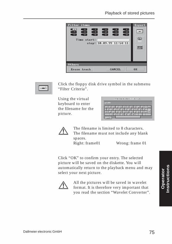
Click the floppy disk drive symbol in the submenu“Filter Criteria”.
Using the virtualkeyboard to enterthe filename for thepicture.
The filename is limited to 8 characters.The filename must not include any blankspaces.Right: frame01 Wrong: frame 01
Click “OK” to confirm your entry. The selectedpicture will be saved on the diskette. You willautomatically return to the playback menu and mayselect your next picture.
All the pictures will be saved in waveletformat. It is therefore very important thatyou read the section “Wavelet Converter”.
Playback of stored pictures
Op
era
tor
Instr
uctio
ns

76
DLS-6 and -18
Dallmeier electronic GmbH
Storing picture sequences on video tape
The system is equipped with a feature enabling youto define a time period, thus making it possible tostore and archive complete picture sequences.Click the “Extras” button in playback mode. Youwill now find yourself in the submenu “CameraFilter”.
Now select the camera(s) with the picture sequencesyou wish to archive, by clicking the correspondingcamera symbol(s). The selected camera(s) can beidentified by the illuminated camera symbol(s).
Now click in the field next to the panel “time periodfrom:”.
In the next menu set the date and starting time(oldest picture to be transfered).
77Dallmeier electronic GmbH
Click the date. Adjust the date using the “arrow up”and “arrow down” keys.
To set the time, click the hours, minutes or secondsdisplay. The relevant segment of the display isilluminated. Use the “arrow up” and “arrow down”keys to set the starting time.
Confirm with “OK”.
Now click the field next to the panel “time perioduntil:” and adjust the date and time in the same wayas described above.
Before adjustment the date and time of the lastrecorded picture are displayed in this field.
Confirm with “OK”.
Before transferring always check that the videorecorder is properly connected. The video input ofthe recorder should be connected to the loop-through output of the monitor.
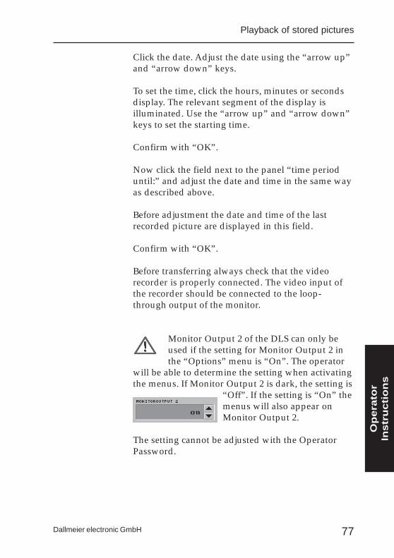
Monitor Output 2 of the DLS can only beused if the setting for Monitor Output 2 inthe “Options” menu is “On”. The operator
will be able to determine the setting when activatingthe menus. If Monitor Output 2 is dark, the setting is
“Off”. If the setting is “On” themenus will also appear onMonitor Output 2.
The setting cannot be adjusted with the OperatorPassword.
Playback of stored pictures
Op
era
tor
Instr
uctio
ns
78
DLS-6 and -18
Dallmeier electronic GmbH
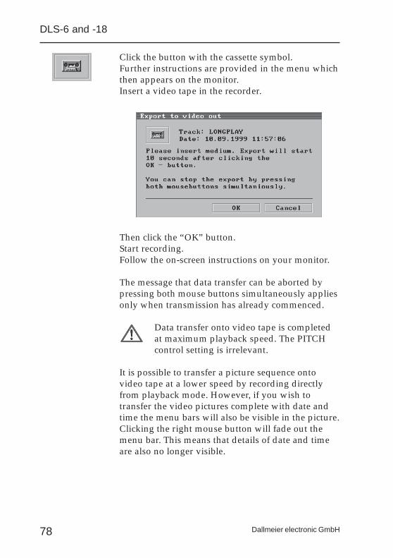
Click the button with the cassette symbol.Further instructions are provided in the menu whichthen appears on the monitor.Insert a video tape in the recorder.
Then click the “OK” button.Start recording.Follow the on-screen instructions on your monitor.
The message that data transfer can be aborted bypressing both mouse buttons simultaneously appliesonly when transmission has already commenced.
Data transfer onto video tape is completedat maximum playback speed. The PITCHcontrol setting is irrelevant.
It is possible to transfer a picture sequence ontovideo tape at a lower speed by recording directlyfrom playback mode. However, if you wish totransfer the video pictures complete with date andtime the menu bars will also be visible in the picture.Clicking the right mouse button will fade out themenu bar. This means that details of date and timeare also no longer visible.

79Dallmeier electronic GmbH
Transfer onto external digital media
The transfer of data from the DLS on to a JAZ Driveor MOD is only possible with an SCSI Interface(option).
Select the cameras and time period for the picturesyou wish to transfer in the menu “Filter Criteria”, asdescribed in the previous section.
Then click the button with the cassette symbols(DSS).
Using the virtualkeyboard, enter atrack name of yourchoice.
The term “Track name” does not refer to therecording track (Longplay or Alarm) but tothe picture sequence to be transferred - alsoa track.
Confirm your entry with “OK”.
Playback of stored pictures
Op
era
tor
Instr
uctio
ns
80
DLS-6 and -18
Dallmeier electronic GmbH
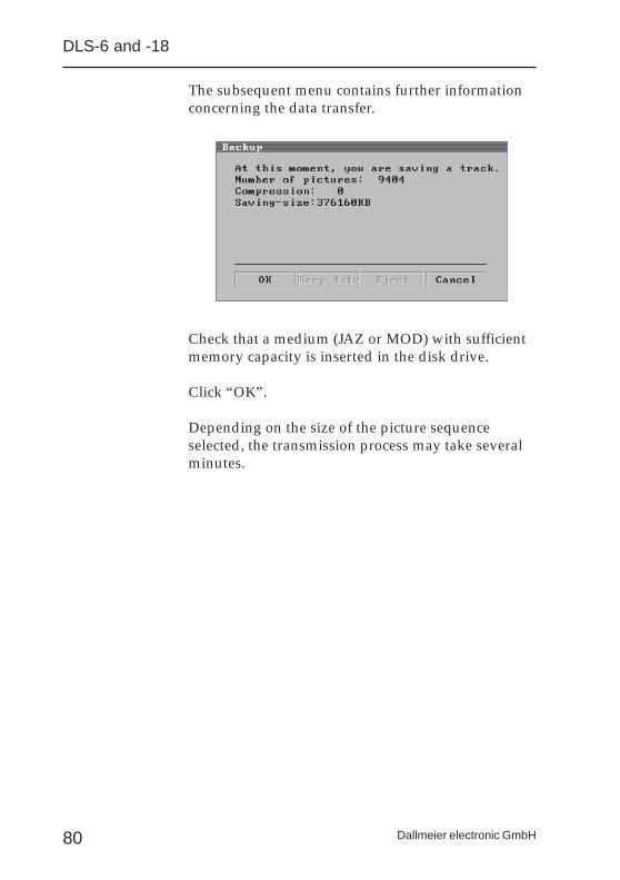
The subsequent menu contains further informationconcerning the data transfer.
Check that a medium (JAZ or MOD) with sufficientmemory capacity is inserted in the disk drive.
Click “OK”.
Depending on the size of the picture sequenceselected, the transmission process may take severalminutes.
81Dallmeier electronic GmbH
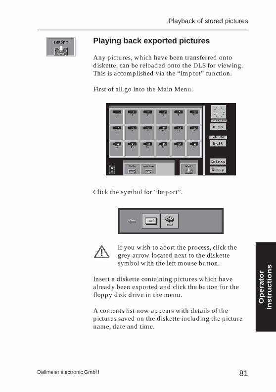
Playing back exported pictures
Any pictures, which have been transferred ontodiskette, can be reloaded onto the DLS for viewing.This is accomplished via the “Import” function.
First of all go into the Main Menu.
Click the symbol for “Import”.
If you wish to abort the process, click thegrey arrow located next to the diskettesymbol with the left mouse button.
Insert a diskette containing pictures which havealready been exported and click the button for thefloppy disk drive in the menu.
A contents list now appears with details of thepictures saved on the diskette including the picturename, date and time.
Playback of stored pictures
Op
era
tor
Instr
uctio
ns
82
DLS-6 and -18
Dallmeier electronic GmbH
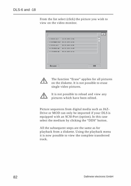
From the list select (click) the picture you wish toview on the video monitor.
The function “Erase” applies for all pictureson the diskette. It is not possible to erasesingle video pictures.
It is not possible to reload and view anypictures which have been edited.
Picture sequences from digital media such as JAZ-Drive or MOD can only be imported if your DLS isequipped with an SCSI-Port (option). In this caseselect the medium by clicking the “DDS” button.
All the subsequent steps are the same as forplayback from a diskette. Using the playback menuit is now possible to view the complete transferredtrack.
83Dallmeier electronic GmbH
Operator Setup
Some of the configuration steps already described inthe Administrator Setup can also be performed andamended by the operator. In this section only thesetup path is described. For more detailed setupinstructions refer to the relevant section of theAdministrator Setup.
To activate to the Operator Setup:
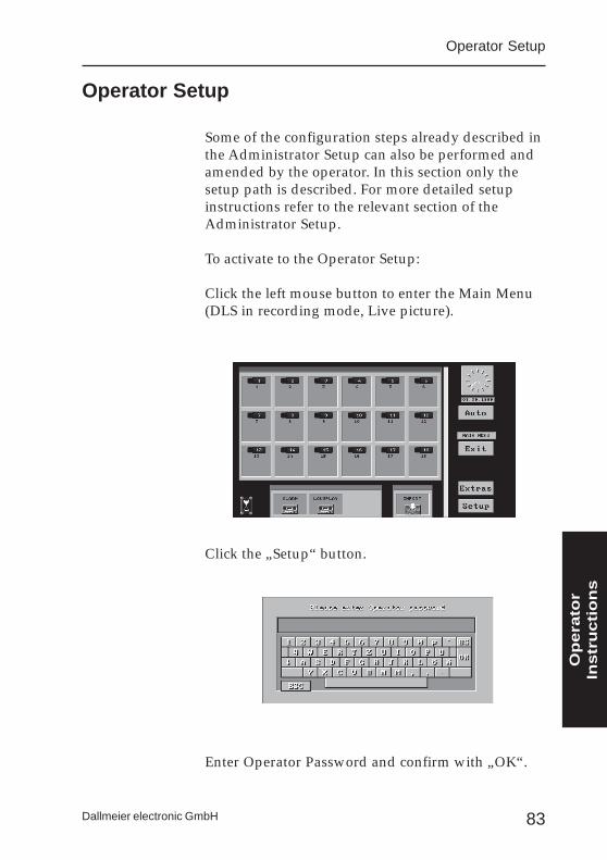
Click the left mouse button to enter the Main Menu(DLS in recording mode, Live picture).
Click the „Setup“ button.
Enter Operator Password and confirm with „OK“.
Operator Setup
Op
era
tor
Instr
uctio
ns
84
DLS-6 and -18
Dallmeier electronic GmbH
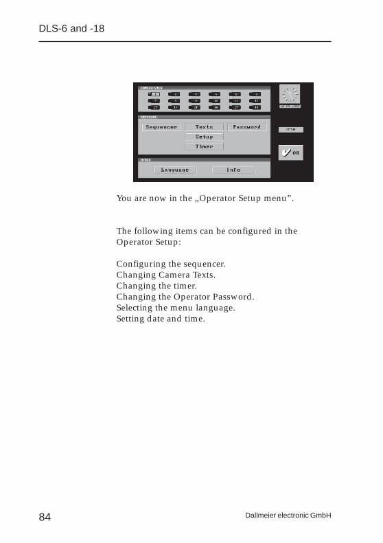
You are now in the „Operator Setup menu”.
The following items can be configured in theOperator Setup:
Configuring the sequencer.Changing Camera Texts.Changing the timer.Changing the Operator Password.Selecting the menu language.Setting date and time.
85Dallmeier electronic GmbH
Configuring the Sequencer
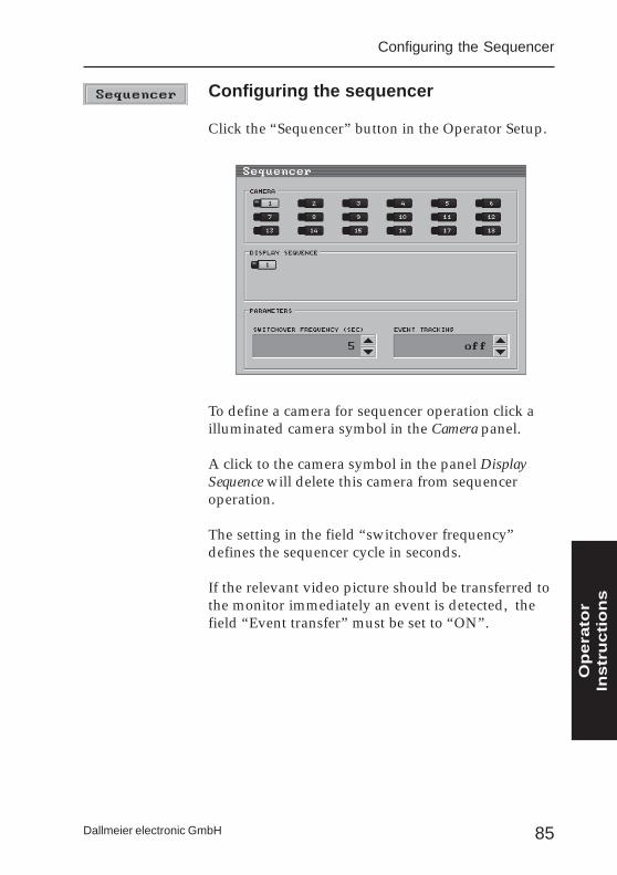
Configuring the sequencer
Click the “Sequencer” button in the Operator Setup.
To define a camera for sequencer operation click ailluminated camera symbol in the Camera panel.
A click to the camera symbol in the panel DisplaySequence will delete this camera from sequenceroperation.
The setting in the field “switchover frequency”defines the sequencer cycle in seconds.
If the relevant video picture should be transferred tothe monitor immediately an event is detected, thefield “Event transfer” must be set to “ON”.
Op
era
tor
Instr
uctio
ns
86
DLS-6 and -18
Dallmeier electronic GmbH
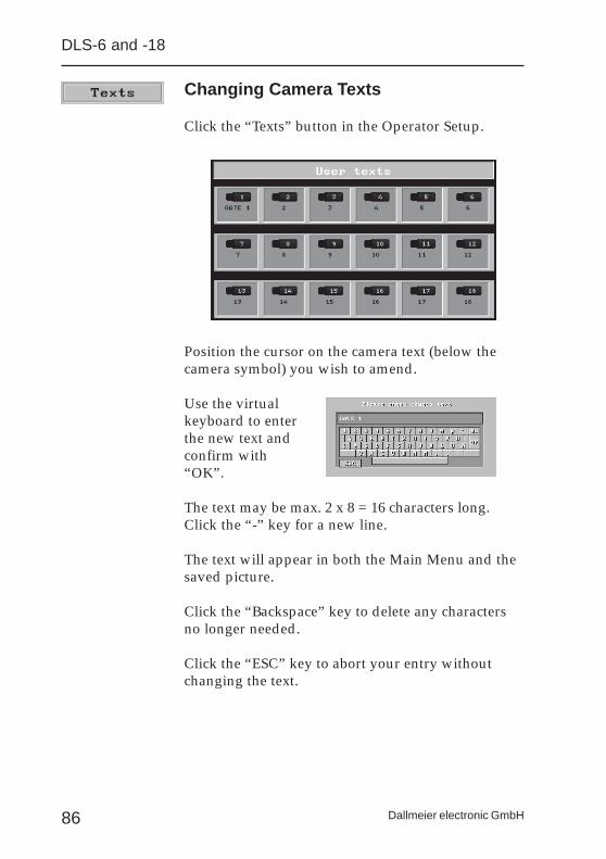
Changing Camera Texts
Click the “Texts” button in the Operator Setup.
Position the cursor on the camera text (below thecamera symbol) you wish to amend.
Use the virtualkeyboard to enterthe new text andconfirm with“OK”.
The text may be max. 2 x 8 = 16 characters long.Click the “-” key for a new line.
The text will appear in both the Main Menu and thesaved picture.
Click the “Backspace” key to delete any charactersno longer needed.
Click the “ESC” key to abort your entry withoutchanging the text.
87Dallmeier electronic GmbH
Setting the timer
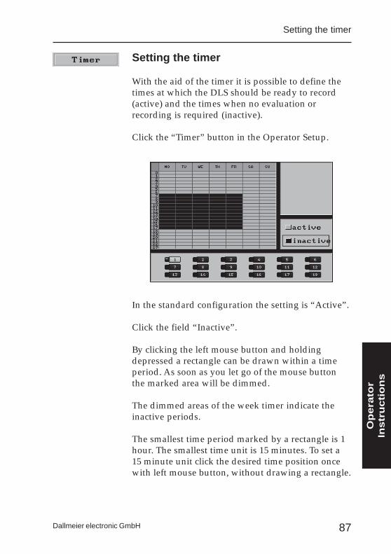
Setting the timer
With the aid of the timer it is possible to define thetimes at which the DLS should be ready to record(active) and the times when no evaluation orrecording is required (inactive).
Click the “Timer” button in the Operator Setup.
In the standard configuration the setting is “Active”.
Click the field “Inactive”.
By clicking the left mouse button and holdingdepressed a rectangle can be drawn within a timeperiod. As soon as you let go of the mouse buttonthe marked area will be dimmed.
The dimmed areas of the week timer indicate theinactive periods.
The smallest time period marked by a rectangle is 1hour. The smallest time unit is 15 minutes. To set a15 minute unit click the desired time position oncewith left mouse button, without drawing a rectangle.
Op
era
tor
Instr
uctio
ns
88
DLS-6 and -18
Dallmeier electronic GmbH
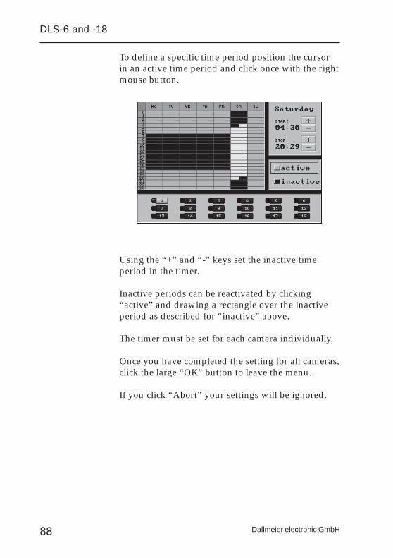
To define a specific time period position the cursorin an active time period and click once with the rightmouse button.
Using the “+” and “-” keys set the inactive timeperiod in the timer.
Inactive periods can be reactivated by clicking“active” and drawing a rectangle over the inactiveperiod as described for “inactive” above.
The timer must be set for each camera individually.
Once you have completed the setting for all cameras,click the large “OK” button to leave the menu.
If you click “Abort” your settings will be ignored.
89Dallmeier electronic GmbH
Changing the Operator Password
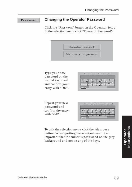
Click the “Password” button in the Operator Setup.In the selection menu click “Operator Password”.
Type your newpassword on thevirtual keyboardand confirm yourentry with “OK”.
Repeat your newpassword andconfirm the entrywith “OK”
To quit the selection menu click the left mousebutton. When quitting the selection menu it isimportant that the cursor is positioned on the greybackground and not on any of the keys.
Changing the Password
Op
era
tor
Instr
uctio
ns
90
DLS-6 and -18
Dallmeier electronic GmbH
Changing the menu language
Click the “Language” button in the Operator Setupto change the menu language.
Continue to click the “Language” button until themenu language you require appears.
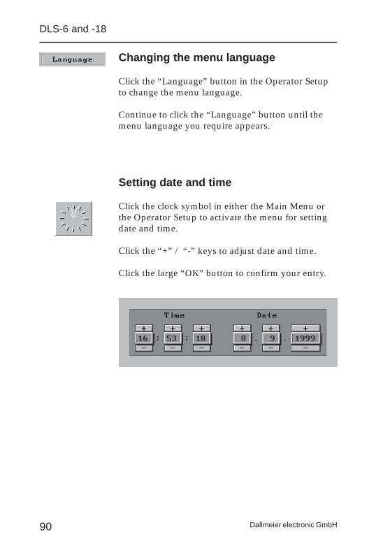
Setting date and time
Click the clock symbol in either the Main Menu orthe Operator Setup to activate the menu for settingdate and time.
Click the “+” / “-” keys to adjust date and time.
Click the large “OK” button to confirm your entry.
91Dallmeier electronic GmbH
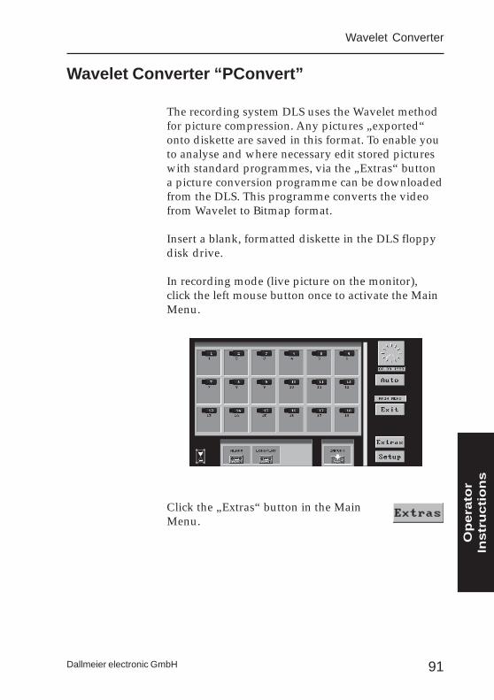
The recording system DLS uses the Wavelet methodfor picture compression. Any pictures „exported“onto diskette are saved in this format. To enable youto analyse and where necessary edit stored pictureswith standard programmes, via the „Extras“ buttona picture conversion programme can be downloadedfrom the DLS. This programme converts the videofrom Wavelet to Bitmap format.
Insert a blank, formatted diskette in the DLS floppydisk drive.
In recording mode (live picture on the monitor),click the left mouse button once to activate the MainMenu.
Click the „Extras“ button in the MainMenu.
Wavelet Converter “PConvert”
Wavelet Converter
Op
era
tor
Instr
uctio
ns
92
DLS-6 and -18
Dallmeier electronic GmbH
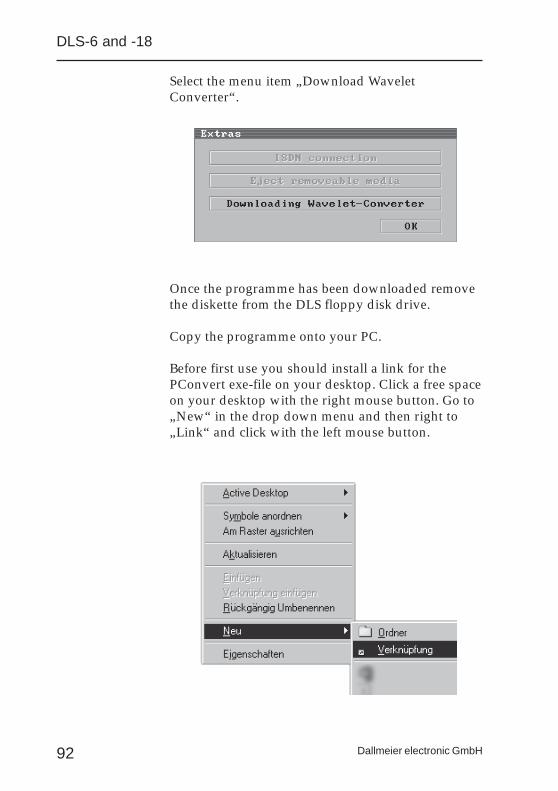
Select the menu item „Download WaveletConverter“.
Once the programme has been downloaded removethe diskette from the DLS floppy disk drive.
Copy the programme onto your PC.
Before first use you should install a link for thePConvert exe-file on your desktop. Click a free spaceon your desktop with the right mouse button. Go to„New“ in the drop down menu and then right to„Link“ and click with the left mouse button.
93Dallmeier electronic GmbH
Wavelet Converter
In the next menu, click „Search“ toselect the path containing the„PConvert.exe“ file. Mark this file andfinish the link with „Open“, „Next“and „Complete“. The PConvert iconappears on the desktop.
Before using the programmeone small tip. Create twofiles in your file directory.Copy the picturesdownloaded from the DLSinto the first file (e.g. “wltpictures”). The second file
(e.g. “bmp pictures”) can be used to save the picturematerial converted into bitmap format. The wltpictures can also be converted directly from thediskette without being saved on the hard disk first.However the bmp pictures have to be saved on thehard disk as the bmp files are much larger thanWavelet files.
Easier still, create one file for both „wlt“ and„bmp“ pictures. On conversion the filedirectory for the wlt pictures willautomatically be adopted for your bmppictures.
Op
era
tor
Instr
uctio
ns
94
DLS-6 and -18
Dallmeier electronic GmbH
Converting Wavelet pictures
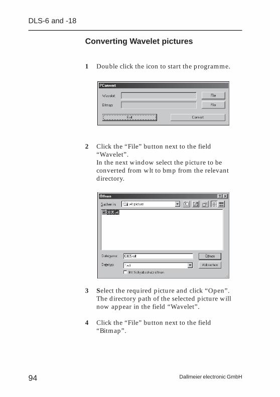
1 Double click the icon to start the programme.
2 Click the “File” button next to the field“Wavelet”.In the next window select the picture to beconverted from wlt to bmp from the relevantdirectory.
3 Select the required picture and click “Open”.The directory path of the selected picture willnow appear in the field “Wavelet”.
4 Click the “File” button next to the field“Bitmap”.
95Dallmeier electronic GmbH
Wavelet Converter
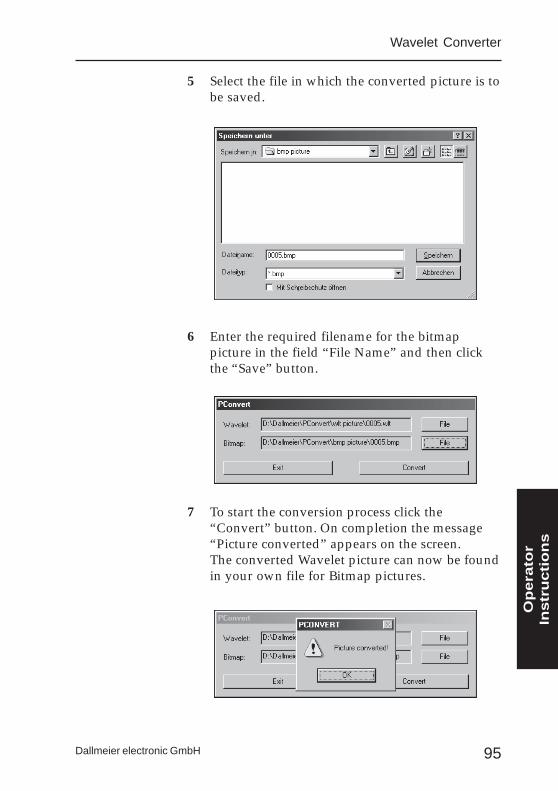
5 Select the file in which the converted picture is tobe saved.
6 Enter the required filename for the bitmappicture in the field “File Name” and then clickthe “Save” button.
7 To start the conversion process click the“Convert” button. On completion the message“Picture converted” appears on the screen.The converted Wavelet picture can now be foundin your own file for Bitmap pictures.
Op
era
tor
Instr
uctio
ns

96
DLS-6 and -18
Dallmeier electronic GmbH

97Dallmeier electronic GmbH
Technical Dataand
Contact Layout
Technical Data

98
DLS-6 and -18
Dallmeier electronic GmbH

99Dallmeier electronic GmbH
External Contacts (Contact IN)
Cable: 25-polePlug/Socket: D-SUBMaximum length: 100m
PIN Function
1 Standby / Start Recording2 Ground3 Contact Recording Cam 184 Contact Recording Cam 165 Contact Recording Cam 146 Contact Recording Cam 127 Contact Recording Cam 108 Contact Recording Cam 89 General contact „Lonplay track“
10 Contact Recording Cam 511 Alarm / Start Recording Alarm track12 Contact Recording Cam 213 General contact „Alarm track“14 - - -15 - - -16 Contact Recording Cam 1717 Contact Recording Cam 1518 Contact Recording Cam 1319 Contact Recording Cam 1120 Contact Recording Cam 921 Contact Recording Cam 722 Contact Recording Cam 623 Contact Recording Cam 424 Contact Recording Cam 325 Contact Recording Cam 1
Technical Data
100
DLS-6 and -18
Dallmeier electronic GmbH
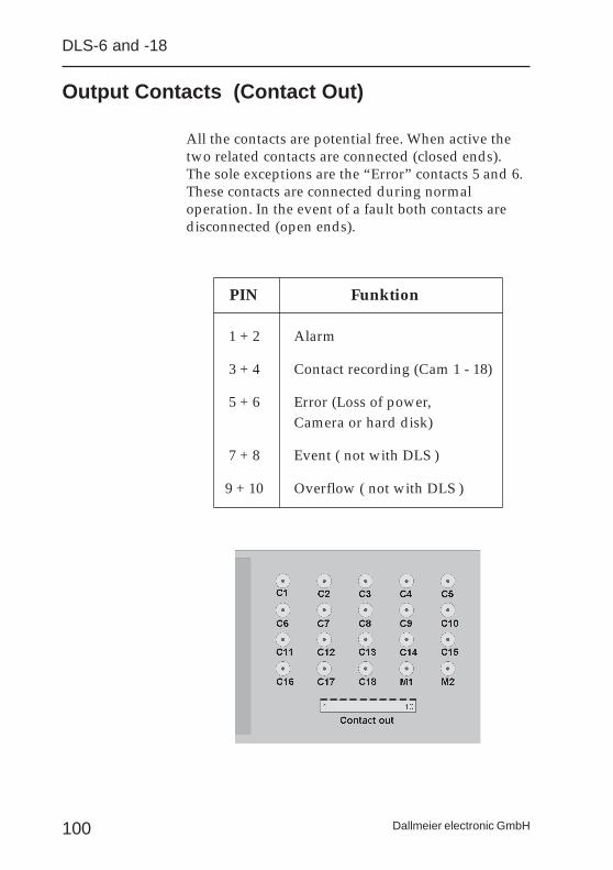
All the contacts are potential free. When active thetwo related contacts are connected (closed ends).The sole exceptions are the “Error” contacts 5 and 6.These contacts are connected during normaloperation. In the event of a fault both contacts aredisconnected (open ends).
Output Contacts (Contact Out)
PIN Funktion
1 + 2 Alarm
3 + 4 Contact recording (Cam 1 - 18)
5 + 6 Error (Loss of power,Camera or hard disk)
7 + 8 Event ( not with DLS )
9 + 10 Overflow ( not with DLS )
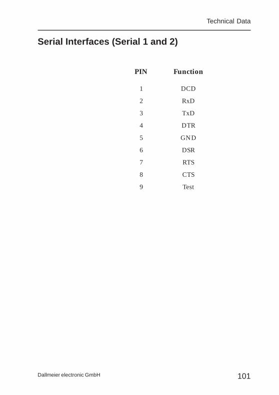
101Dallmeier electronic GmbH
Serial Interfaces (Serial 1 and 2)
PIN Function
1 DCD
2 RxD
3 TxD
4 DTR
5 GND
6 DSR
7 RTS
8 CTS
9 Test
Technical Data

102
DLS-6 and -18
Dallmeier electronic GmbH
Technical Data DLS-6 / DLS-18
Multiplexer
Camera inputs (DLS-6) ......... 6 CVBS / 1 Vpp - 75 Ohm - BNCloop through output
Camera inputs (DLS-18) ....... 18 CVBS / 1 Vpp - 75 Ohm - BNCloop through connection possible
Monitor outputs ..................... 2 CVBS / 1 Vpp - 75 Ohm - BNC
For evaluation and storage of videomaterial from 6/18 cameras.
Picture storage
Resolution ............................... 720 (H) x 288/576 (V)Video Norm ............................ CCIR/PALCompression technique ........... WaveletCompression levels ................. 5 levels - freely configurableCompression ........................... individual setting for each
track type
Storage file
Ring memory ..................... DLS-6 Longplay (540.000 fields)Ring memory ..................... DLS-18 Longplay (1.000.000 fields)Alarm memory .................. Alarm (60.000 fields)
Recording
Contact ............................. setting per cameraMotion detection ............... setting per cameraPermanent ......................... setting per cameraWeek timer ........................ setting per camera
Recording speed
Multi-channel operationSynchronised-Genlock ............. 25 fields/SecondSynchronised-Linelock .............. 12 fields/SecondUnsynchronised ........................ 12 fields/SecondWith motion detection ................ 6 fields/Second
1 channel operationwith motion detection ................. 9 fields/Secondw/o motion detection ............... 50 fields/Second
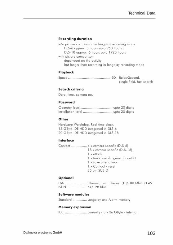
103Dallmeier electronic GmbH
Technical Data
Recording duration
w/o picture comparison in longplay recording modeDLS-6 approx. 3 hours upto 960 hours.DLS-18 approx. 6 hours upto 1920 hours
with picture comparisondependant on the activitybut longer than recording in longplay recording mode
Playback
Speed ............................................. 50 fields/Second,single field, fast search
Search criteria
Date, time, camera no.
Password
Operater level .................................. upto 20 digitsInstallation level ............................... upto 20 digits
Other
Hardware Watchdog, Real time clock,15 GByte IDE HDD integrated in DLS-620 GByte IDE HDD integrated in DLS-18
Interface
Contact ................. 6 x camera specific (DLS-6)18 x camera specific (DLS-18)1 x attack1 x track specific general contact1 x save after attack1 x Contact / reset25 pin SUB-D
Optional
LAN ....................... Ethernet, Fast Ethernet (10/100 Mbit) RJ 45ISDN ..................... 64/128 Kbit
Software modules
Standard ............... Longplay and Alarm memory
Memory expansion
IDE ....................... currently - 3 x 36 GByte - internal
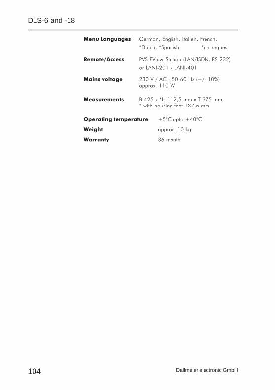
104
DLS-6 and -18
Dallmeier electronic GmbH
Menu Languages German, English, Italien, French,
*Dutch, *Spanish *on request
Remote/Access PVS PView-Station (LAN/ISDN, RS 232)
or LANI-201 / LANI-401
Mains voltage 230 V / AC - 50-60 Hz (+/- 10%)approx. 110 W
Measurements B 425 x *H 112,5 mm x T 375 mm* with housing feet 137,5 mm
Operating temperature +5°C upto +40°C
Weight approx. 10 kg
Warranty 36 month
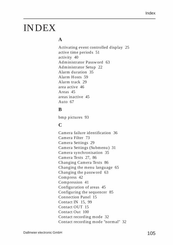
105Dallmeier electronic GmbH
INDEX
Index
A
Activating event controlled display 25active time periods 51activity 40Administrator Password 63Administrator Setup 22Alarm duration 35Alarm Hosts 59Alarm track 29area active 46Areas 45areas inactive 45Auto 67
B
bmp pictures 93
C
Camera failure identification 36Camera Filter 73Camera Settings 29Camera Settings (Submenu) 31Camera synchronisation 35Camera Texts 27, 86Changing Camera Texts 86Changing the menu language 65Changing the password 63Compress 42Compression 41Configuration of areas 45Configuring the sequencer 85Connection Panel 15Contact IN 15, 99Contact OUT 15Contact Out 100Contact recording mode 32Contact recording mode "normal" 32

106
DLS-6 and -18
Dallmeier electronic GmbH
Contact recording mode "start" 32Contact recording mode "timer" 32Contact recording mode "toggle" 32Contact recording time 32, 33Convert 95Converting Wavelet pictures 94
D
date and time 90DDS 82Default 54Defining active time periods 51Defining inactive time periods 49Devicename 58digital media 79Download Wavelet Converter 92
E
Ethernet / Tokenring 56Event 33Event transfer 85Exporting pictures 74Extensions - Code 54External Contacts 99Extras 73, 91
F
Fast picture search 72Filter Criteria 75First Operation 17Forward playback 71Front panel 16
G
genlock 40
I
Import 81inactive time periods 49Info Menu 66
107Dallmeier electronic GmbH
Index
Info menu 18IP-Address 59ISDN 57, 61
J
JAZ Drive 79
K
Keyboard Mode 36
L
language 65Language; Changing the menu language 65Levels of Compression 41linelock 40Longplay track 29Loop-through outputs 14
M
Main Menu 20Main password test 36Memory capacity utilization 44menu language 90Menu "Options" 35Menu "Service" 53Messages 60MOD 79Monitor Output 2 77Monitor output 2 36Monitor outputs 15Motion detection display 37
N
Network - Export 55Network - Import 55Network - Setup 55normal 32Number of pictures 39

108
DLS-6 and -18
Dallmeier electronic GmbH
O
Operator Password 19, 22, 63, 89Operator Setup 83Operator Texts 27Options 35Output Contacts 100
P
Parameter 53Parameter - Default 54Parameter - Export 53Parameter - Import 53Password 19, 63PConvert 91Picture area active 46Picture areas inactive 45Picture Comparison 45Picture comparison / Sensitivity 31Picture comparison display 37Picture quality 42Picture rates 40Picture search 72Playback 71Playback of stored pictures 71Playback speed 72Playing back exported pictures 81PS/2-Mouse 15
R
Recording 67Recording interval - Alarm 34Recording interval - Normal 34Recording mode 31Recording; Start recording 67Resolution - Alarm 34Resolution - Normal 34Reverse playback 71
109Dallmeier electronic GmbH
Index
S
Safety Instructions 7Save 33SCSI Interface 79SCSI-Port 16Sequencer 85Sequencer, Configuring the sequencer 23Sequencer operation 67Sequencer; Activating event controlled display 25Sequencer; Defining cameras for the sequencer 23Sequencer; Deleting cameras 24Sequencer; Disabling cameras 24Sequencer; Display Sequence 23Sequencer; Switchover frequency 25Serial 1 and 2 16Serial Interfaces 101Service socket 15Setting date and time 90Setting the week timer 49Setup Menus 22Single frame forward playback 71Single frame reverse playback 71Slots 16Software - Update 54Software version 66Start 32Status 60Switching off the system 21Switchover frequency 85System parameters 53
T
TAC-18 36TCI-24 36Technical Data 102time interval 50time period 76, 79time periods 49
110
DLS-6 and -18
Dallmeier electronic GmbH
timer 32Timer; Active 87Timer; Inactive 87Timer; Setting the timer 87toggle 32Track configuration 39Track name 79
U
Update 54Upgrade 54Utilization 44
V
Video inputs 15Video tape 76, 78
W
Wavelet 94Wavelet Converter 75, 91week timer 49wlt pictures 93
111Dallmeier electronic GmbH
EG-KEG-KEG-KEG-KEG-Konfonfonfonfonfororororormitätsermitätsermitätsermitätsermitätserklärklärklärklärklär ungungungungungDeclaration of Conformity
PrPrPrPrProdukt:odukt:odukt:odukt:odukt: DMS-180/II, DMS-6KB, DLS-6, DLS-18product:
Hersteller:Hersteller:Hersteller:Hersteller:Hersteller: Dallmeier electronicmanufacturer: VIDEOCONTROLLSYSTEME GmbH
Würzburger Str. 5D - 93059 Regensburg
Wir erklären als Hersteller eigenverantwortlich, daß oben genannte Produktefolgende EG-Richtlinien erfüllen:As manufacturer we declare that the products named above are inaccordance with the following EC-Directives:
• Elektromagnetische Verträglichkeit 89/336/EWG electromagnetic compatibility
• Niederspannung 73/23/EWG low voltage
Folgende Normen wurden angewandt:The following specifications were applied:
• Störemissionen / Emmissions: Grenzwertklasse B nach EN 55022: 1998• Störfestigkeit / Immunity: Grenzwertklasse B nach EN 55024: 1998• DIN EN 60950 (VDE 0805):1997-11 + A11:1998-08• IEC 950:1991 + A1:1992 + A2:1993 + A3:1995 + A4:1996
Regensburg, 20.05.1999 gez. Dieter DallmeierGeschäftsführer
General Manager