dlc- Unit 3
18
Mrs.V.Geetha Priya/ EEE / REC 1 UNIT – IV ASYNCHRONOUS S EQUENTIAL CIRCUITS
-
Upload
bala-subramanian -
Category
Documents
-
view
237 -
download
0
Transcript of dlc- Unit 3

7/30/2019 dlc- Unit 3
http://slidepdf.com/reader/full/dlc-unit-3 1/34
Mrs.V.Geetha Priya/ EEE / REC 1
UNIT – IV
ASYNCHRONOUS SEQUENTIALCIRCUITS
7/30/2019 dlc- Unit 3
http://slidepdf.com/reader/full/dlc-unit-3 2/34
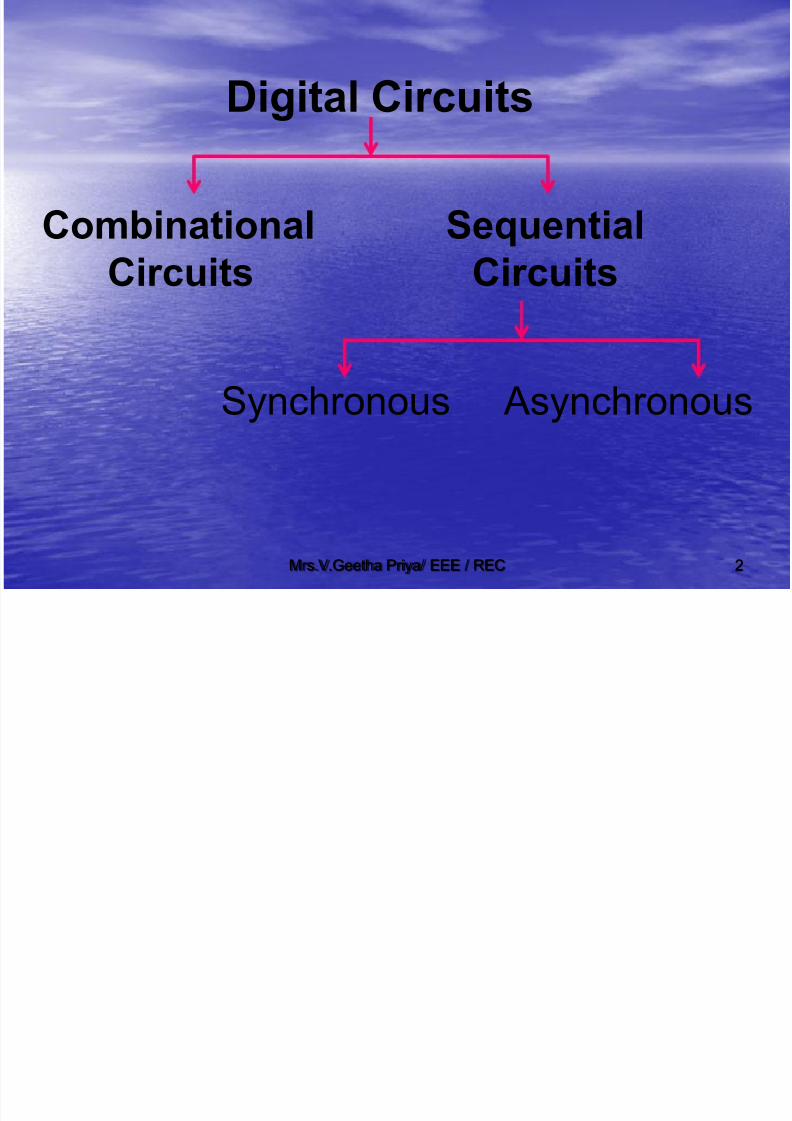
Mrs.V.Geetha Priya/ EEE / REC 2
Digital Circuits Combinational Sequential
Circuits Circuits
Synchronous Asynchronous
7/30/2019 dlc- Unit 3
http://slidepdf.com/reader/full/dlc-unit-3 3/34
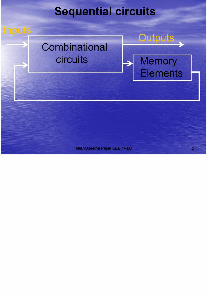
Mrs.V.Geetha Priya/ EEE / REC 3
Sequential circuits
Memory
Elements
InputsOutputs
Combinational
circuits
7/30/2019 dlc- Unit 3
http://slidepdf.com/reader/full/dlc-unit-3 4/34
Mrs.V.Geetha Priya/ EEE / REC 4
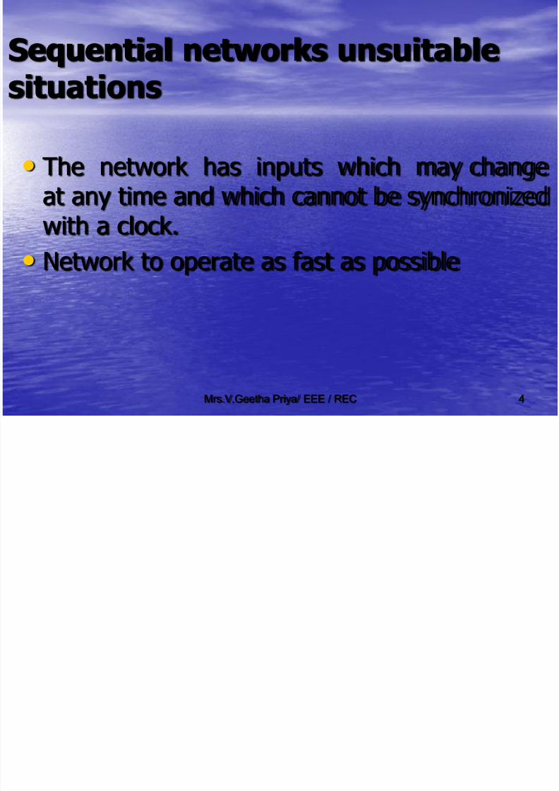
Sequential networks unsuitable
situations
• The network has inputs which may change
at any time and which cannot be synchronizedwith a clock.
• Network to operate as fast as possible
7/30/2019 dlc- Unit 3
http://slidepdf.com/reader/full/dlc-unit-3 5/34
Mrs.V.Geetha Priya/ EEE / REC 5
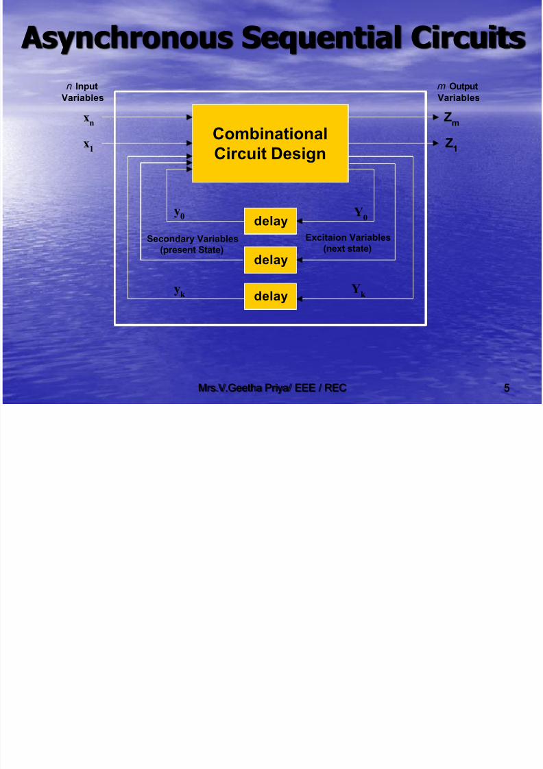
Asynchronous Sequential Circuits
Combinational
Circuit Design
Zm
Z1
xn
x1
y0
yk
Y0
Yk
Secondary Variables
(present State)
Excitaion Variables
(next state)
n Input
Variables
m Output
Variables
delay
delay
delay

7/30/2019 dlc- Unit 3
http://slidepdf.com/reader/full/dlc-unit-3 6/34
Mrs.V.Geetha Priya/ EEE / REC 6
Modes of operation
Fundamental mode
Input signals will be changed only when the
circuit is in a stable state.
(no internal signals are changing)
Input signals are considered as levels
Asynchronous SequentialCircuits
7/30/2019 dlc- Unit 3
http://slidepdf.com/reader/full/dlc-unit-3 7/34
Mrs.V.Geetha Priya/ EEE / REC 7
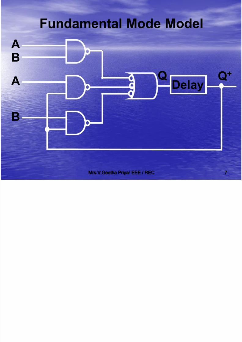
Fundamental Mode Model
AB
A
B
DelayQ+Q

7/30/2019 dlc- Unit 3
http://slidepdf.com/reader/full/dlc-unit-3 8/34
Mrs.V.Geetha Priya/ EEE / REC 8
Analysis of asynchronous sequential
circuits
S2 Q2
R2 Q2
S1 Q1
R1 Q1
X
S1 = X Q2;
S2 = Q1;
R1 = X Q2 ;
R2 = Q1

7/30/2019 dlc- Unit 3
http://slidepdf.com/reader/full/dlc-unit-3 9/34
Mrs.V.Geetha Priya/ EEE / REC 9
S1 = X Q2; S2 = Q1;
R1 = X Q2 ; R2 = Q1;
Characteristic equation:
Q1+ = S1 + R1 Q1 Q2
+ = S2 + R2 Q2
= XQ2 + XQ2Q1 = Q1 + Q1Q2
Q1+ = X Q2; Q2
+ = Q1

7/30/2019 dlc- Unit 3
http://slidepdf.com/reader/full/dlc-unit-3 10/34
Mrs.V.Geetha Priya/ EEE / REC 10
Transition (or) Flow Table
Q1+ = X Q2;
Q2+ = Q1
1101
0101
0000
1000
00
01
11
10
Q1Q2
X0 1

7/30/2019 dlc- Unit 3
http://slidepdf.com/reader/full/dlc-unit-3 11/34
Mrs.V.Geetha Priya/ EEE / REC 11
Asynchronous Sequential Circuit
Design - Steps1). Primitive flow table
2). State reduction3). State assignment
4). Output assignment5). Realization using logic gates
7/30/2019 dlc- Unit 3
http://slidepdf.com/reader/full/dlc-unit-3 12/34
Mrs.V.Geetha Priya/ EEE / REC 12
Design Example:
Design a T Flip Flop where the flip flophas two inputs T and P. The FF will
change state if T = 1 when the P input
changes from 1 to 0. Under all other input conditions the FF Output Q
should remain constant. Assume that T
and P do not change simultaneously.
7/30/2019 dlc- Unit 3
http://slidepdf.com/reader/full/dlc-unit-3 13/34
Mrs.V.Geetha Priya/ EEE / REC 13
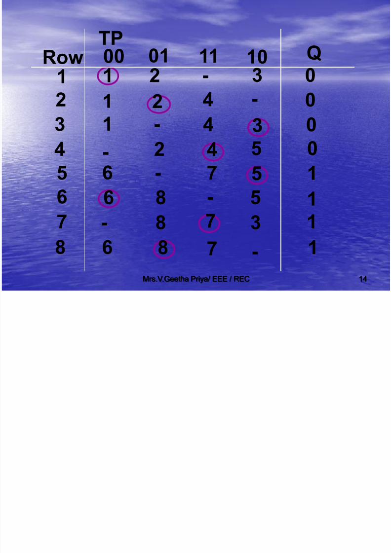
Step 1: Primitive Flow Table
Assumptions:
• One Stable state per row.
• Only one input variable changes at
a time.
•Every input change must result ina state change.
7/30/2019 dlc- Unit 3
http://slidepdf.com/reader/full/dlc-unit-3 14/34
Mrs.V.Geetha Priya/ EEE / REC 14
2
3
4
5
67
8
1 1
1
1
-6
-
6
6
2
2
2
-
-
88
8 7
7
7
-
4
4
4
0
0
0
0
1
11
1-
35
5
5
3
-3-
TPRow Q00 01 11 10

7/30/2019 dlc- Unit 3
http://slidepdf.com/reader/full/dlc-unit-3 15/34
Mrs.V.Geetha Priya/ EEE / REC 15
Step 2: State Reduction
Necessity :
To reduce number of rows which in
turn reduces the number of statevariables in the hardware
implementation.

7/30/2019 dlc- Unit 3
http://slidepdf.com/reader/full/dlc-unit-3 16/34
Mrs.V.Geetha Priya/ EEE / REC 16
Steps to reduce number of rows
•
To find equivalent stable totalstates
•
Merging of rows

7/30/2019 dlc- Unit 3
http://slidepdf.com/reader/full/dlc-unit-3 17/34
Mrs.V.Geetha Priya/ EEE / REC 17
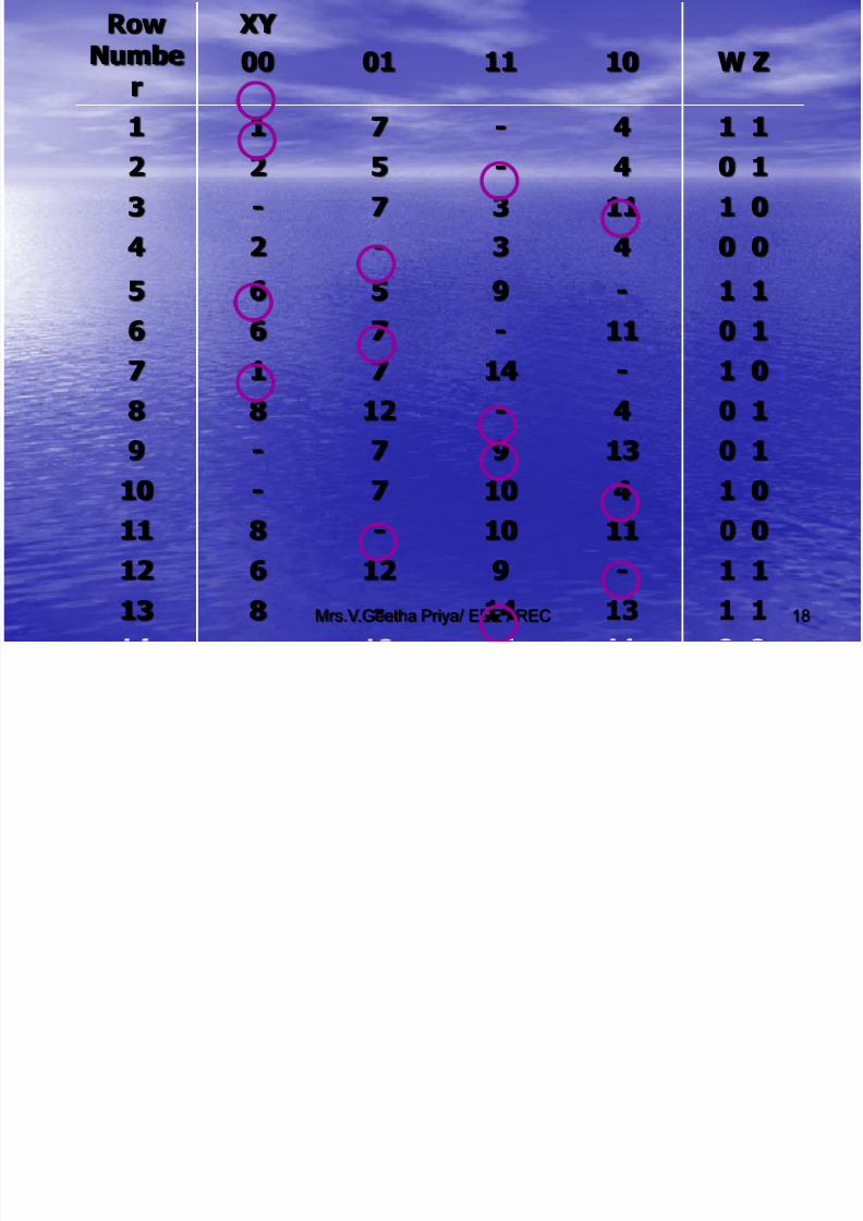
Definition :
Two stable total states are equivalent
if,
i) Inputs are same.
ii) Outputs are same.
iii) Their next states are equivalent
for each possible next input.
7/30/2019 dlc- Unit 3
http://slidepdf.com/reader/full/dlc-unit-3 18/34
Mrs.V.Geetha Priya/ EEE / REC 18
RowNumbe
r
XY
00 01 11 10 W Z
1 1 7 - 4 1 1
2 2 5 - 4 0 1
3 - 7 3 11 1 0
4 2 - 3 4 0 0
5 6 5 9 - 1 16 6 7 - 11 0 1
7 1 7 14 - 1 0
8 8 12 - 4 0 1
9 - 7 9 13 0 110 - 7 10 4 1 0
11 8 - 10 11 0 0
12 6 12 9 - 1 1
13 8 - 14 13 1 1

7/30/2019 dlc- Unit 3
http://slidepdf.com/reader/full/dlc-unit-3 19/34
Mrs.V.Geetha Priya/ EEE / REC 19
2 6 , 6 8, 5 7, 7 12, 3 9, 9 10,
9 14, 10 14, 11 13
2 = 8 , 5 = 12, 3 = 10 and 4 = 11
Row XY

7/30/2019 dlc- Unit 3
http://slidepdf.com/reader/full/dlc-unit-3 20/34
Mrs.V.Geetha Priya/ EEE / REC 20
RowNumbe
r
XY
00 01 11 10 W Z
1 1 7 - 4 1 1
2 2 5 - 4 0 1
3 - 7 3 11 1 0
4 2 - 3 4 0 0
5 6 5 9 - 1 1
6 6 7 - 11 0 1
7 1 7 14 - 1 0
8 8 12 - 4 0 1
9 - 7 9 13 0 110 - 7 10 4 1 0
11 8 - 10 11 0 0
12 6 12 9 - 1 1
13 8 - 14 13 1 1
2
5 4
4
4
2 = 8
3=10
4=11
5=12

7/30/2019 dlc- Unit 3
http://slidepdf.com/reader/full/dlc-unit-3 21/34
Mrs.V.Geetha Priya/ EEE / REC 21
1 14-711
XY RowNumber 00 01 11 10
0 14-5221 0437-30 043-24
1 1-9550 14-7661 0-14717
0 04145-14
1 11314-213 0 11397-9
6
W Z

7/30/2019 dlc- Unit 3
http://slidepdf.com/reader/full/dlc-unit-3 22/34
Mrs.V.Geetha Priya/ EEE / REC 22
State Reduction
21
3
456
7
8
TPRow
1
1
1
-6
-
6
6
2
2
2-
-
8
8
8 7
7
7-
4
4
4
Q0
0
00
1
11
1-
3
5
5
5
3-3
00 01 11 10- 1 6
2
84 7
3 5

7/30/2019 dlc- Unit 3
http://slidepdf.com/reader/full/dlc-unit-3 23/34
Mrs.V.Geetha Priya/ EEE / REC 23
21
3
456
7
8
TPRow
1
11
-6
-
6
6
2
2
2
-
-
8
8
8 77
7-
4
4
4
Q
0
0
00
1
11
1-3
55
53
-3
00 01 11 10
- 1
2
3
45
7
6
8
Rows (1,2,3) can be merged
Rows 5 6 8 can be mer ed.
Merging

7/30/2019 dlc- Unit 3
http://slidepdf.com/reader/full/dlc-unit-3 24/34
Mrs.V.Geetha Priya/ EEE / REC 24
1,2,3
4
5,6,8
7
TP
Row
1
-
6
-
2
2
8
8 7
7
4
Q
3
5
5
3
00 01 11 10
4
00 01 11 10
MERGED ROWS

7/30/2019 dlc- Unit 3
http://slidepdf.com/reader/full/dlc-unit-3 25/34
Mrs.V.Geetha Priya/ EEE / REC 25
1,2,3
4
5,6,8
7
TP
Row
1
-
6
-
2
2
8
8 7
7
4
Q
3
5
5
3
00 01 11 10
4
00 01 11 10
0 0 0
0
1 1 1
1
0
0 0
1
1 1
X
X
OUTPUT FILLING
St 3 St t A i t

7/30/2019 dlc- Unit 3
http://slidepdf.com/reader/full/dlc-unit-3 26/34
Mrs.V.Geetha Priya/ EEE / REC 26
Step 3 : State Assignment
1,2,3
4
5,6,8
7
TP
Row1
-
6
-
2
2
8
8 7
7
4
Q
3
5
5
3
00 01 11 10
4
00 01 11 10
0 0 0
0
1 1 1
1
0
0 0
1
1 1
X
X
1) (1,2,3) and 4 should have adjacent assignment
2) 4 and (5,6,8) should have adjacent assignment
3) (5,6,8) and 7 should have adjacent assignment
4) 7 and (1,2,3) should have adjacent assignment
St t A i t td

7/30/2019 dlc- Unit 3
http://slidepdf.com/reader/full/dlc-unit-3 27/34
Mrs.V.Geetha Priya/ EEE / REC 27
0 1Q2Q1
(1,2,3)
4
1) (1,2,3) and 4 should have adjacent assignment
2) 4 and (5,6,8) should have adjacent assignment
3) (5,6,8) and 7 should have adjacent assignment
4) 7 and (1,2,3) should have adjacent assignment
(5,6,8)
7
1) States (1,2,3) Q1Q2 = 00
2) State 4 Q1Q2 = 10 3) State 7 Q1Q2 = 01
4) States (5,6,8) Q1Q2 = 11
0
1
State Assignment contd...
TP Q

7/30/2019 dlc- Unit 3
http://slidepdf.com/reader/full/dlc-unit-3 28/34
Mrs.V.Geetha Priya/ EEE / REC 28
1,2,3(00)
4(10)
5,6,8(11)
7(01)
TP
Row
00
-
11
-
00
00
11
11 01
01
10
Q
00
11
11
00
00 01 11 10
10
00 01 11 10
0 0 0
0
1 1 1
1
0
0 0
1
1 1
X
X
1,2,3
45,6,8
7
TP
Row
1
-6
-
2
28
8 7
74
Q
3
55
3
00 01 11 10
4
00 01 11 10
0 0 0
0
1 1 1
1
0
0 01
1 1
X
X
Q1Q2

7/30/2019 dlc- Unit 3
http://slidepdf.com/reader/full/dlc-unit-3 29/34
Mrs.V.Geetha Priya/ EEE / REC 29
1,2,3(00)
4(10)
5,6,8(11)
7(01)
TP
Row
00
-
11
-
00
00
11
11 01
01
10
Q
00
11
11
00
00 01 11 10
10
00 01 11 10
0 0 0
0
1 1 1
1
0
0 0
1
1 1
X
X
Q1Q2
0 0 1 0
x 0 1 11 1 0 1
x 1 0 0
00 01 11 10Q1Q2
00
01
11
10
TP
Q1+
0 0 0 0
x 0 0 11 1 1 1
x 1 1 0
00 01 11 10Q1Q2
00
01
11
10
TP
Q2+

7/30/2019 dlc- Unit 3
http://slidepdf.com/reader/full/dlc-unit-3 30/34
Mrs.V.Geetha Priya/ EEE / REC 30
0 0 1 0
x 0 1 1
1 1 0 1
x 1 0 0
00 01 11 10Q1Q2
00
01
11
10
TP
0 0 0 0
x 0 0 1
1 1 1 1
x 1 1 0
00 01 11 10Q1Q2
00
01
11
10
TP
Q1
+ = Q1
T+Q2
P+
Q1TP+Q1Q2T
Q2+ = Q1T+Q1P+Q2P

7/30/2019 dlc- Unit 3
http://slidepdf.com/reader/full/dlc-unit-3 31/34
Mrs.V.Geetha Priya/ EEE / REC 31
0 0 0 0x 0 0 0
1 1 1 1
x 1 1 1
00 01 11 10Q1Q2
00
01
11
10
1,2,3(00)
4(10)
5,6,8(11)
7(01)
TP
Row
00
-
11
-
00
00
11
11 01
01
10
Q
00
11
11
00
00 01 11 10
10
00 01 11 10
0 0 0
0
1 1 1
1
0
0 0
1
1 1
X
X
Q1Q2
Z = Q1
Step 4 : Output Assignment

7/30/2019 dlc- Unit 3
http://slidepdf.com/reader/full/dlc-unit-3 32/34
Mrs.V.Geetha Priya/ EEE / REC 32
LOGIC DIAGRAM
Step 5 :

7/30/2019 dlc- Unit 3
http://slidepdf.com/reader/full/dlc-unit-3 33/34
Mrs.V.Geetha Priya/ EEE / REC 33
T
P Q1
Q2
Q1+ = Q1T+Q2P+ Q1TP+Q1Q2T;
Q2+ = Q1T+Q1P+Q2P;
P
Z=Q1

7/30/2019 dlc- Unit 3
http://slidepdf.com/reader/full/dlc-unit-3 34/34
Mrs V Geetha Priya/ EEE / REC 34
Thank you