Dl-C2-Suzuky-maintenance.pdf
31
PERIODIC MAINTENANCE 2-1 CONTENTS PERIODIC MAINTENANCE SCHEDULE ............................................... 2 PERIODIC MAINTENANCE CHART ................................................... 2 LUBRICATION POINTS ......................................................................... 4 MAINTENANCE AND TUNE-UP PROCEDURES ........................................ 5 AIR CLEANER ................................................................................... 5 SPARK PLUG ........................................................................................ 6 VALVE CLEARANCE ............................................................................ 2 8 FUEL LINE ............................................................................................. 2-13 ENGINE OIL AND OIL FILTER ........................................................... 2-13 ENGINE IDLE SPEED ............................................................................ 2-15 THROTTLE CABLE PLA Y ..................................................................... 2-15 THROTTLE VALVE SYNCHRONIZATION ............................................ 2-16 EVAPORATIVE EMISSION CONTROL SYSTEM (E-33 ONLY) ........... 2-16 PAIR (AIR SUPPLY) SYSTEM ............................................................... 2-16 CLUTCH ................................................................................................. 2-17 COOLING SYSTEM ................................... . .................................... 2-18 DRl VE CHAIN ......................................................................................... 2-20 BRAKE ................................................................................................... 2-22 TIRE ........................................................................................................ 2-26 STEERING ............................................................................................. 2.26 FRONT FORK ........................................................................................ 2-27 REAR SUSPENSION ............................................................................. 2-27 EXHAUST PIPE BOLT ........................................................................... 2-27 CHASSIS BOLT AND NUT .................................................................... 2-28 COMPRESSION PRESSURE CHECK ......................................................... 2-30 COMPRESSION TEST PROCEDURE ................................................... 2-30 OIL PRESSURE CHECK .............................................................................. 2-31
-
Upload
nita-stefan-iulian -
Category
Documents
-
view
212 -
download
0
Transcript of Dl-C2-Suzuky-maintenance.pdf

PERIODIC MAINTENANCE 2-1
CONTENTS
PERIODIC MAINTENANCE SCHEDULE ............................................... 2
PERIODIC MAINTENANCE CHART ................................................... 2 LUBRICATION POINTS ......................................................................... 4
MAINTENANCE AND TUNE-UP PROCEDURES ........................................ 5
AIR CLEANER ................................................................................... 5 SPARK PLUG ........................................................................................ 6 VALVE CLEARANCE ............................................................................ 2 8 FUEL LINE ............................................................................................. 2-13 ENGINE OIL AND OIL FILTER ........................................................... 2-13 ENGINE IDLE SPEED ............................................................................ 2-15 THROTTLE CABLE PLA Y ..................................................................... 2-15 THROTTLE VALVE SYNCHRONIZA TION ............................................ 2-16 EVAPORATIVE EMISSION CONTROL SYSTEM (E-33 ONLY) ........... 2-16 PAIR (AIR SUPPLY) SYSTEM ............................................................... 2-16 CLUTCH ................................................................................................. 2-17 COOLING SYSTEM ................................... ...... .................................... 2-18 DRl VE CHAIN ......................................................................................... 2-20 BRAKE ................................................................................................... 2-22 TIRE ........................................................................................................ 2-26 STEERING ............................................................................................. 2.26 FRONT FORK ........................................................................................ 2-27 REAR SUSPENSION ............................................................................. 2-27 EXHAUST PIPE BOLT ........................................................................... 2-27 CHASSIS BOLT AND NUT .................................................................... 2-28
COMPRESSION PRESSURE CHECK ......................................................... 2-30
COMPRESSION TEST PROCEDURE ................................................... 2-30
OIL PRESSURE CHECK .............................................................................. 2-31
2-2 PERIODIC MAINTENANCE
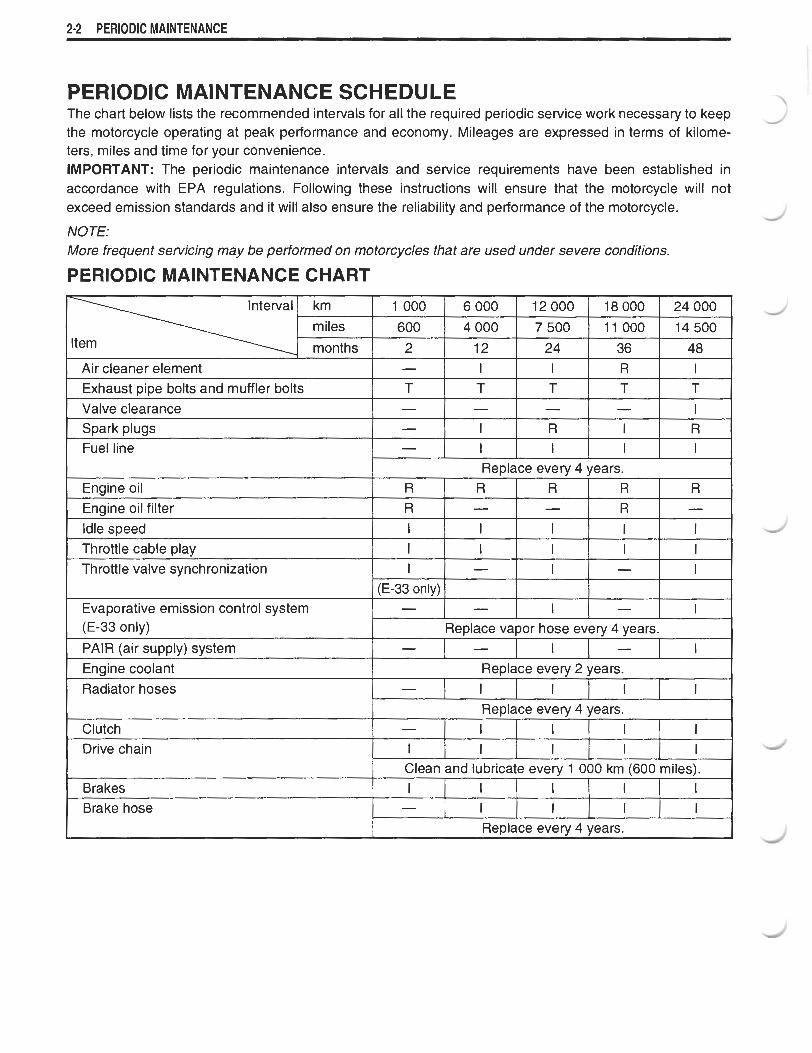
PERIODIC MAINTENANCE SCHEDULE The chart below lists the recommended intervals for all the required periodic service work necessary to keep the motorcycle operating at peak performance and economy. Mileages are expressed in terms of kilome- ters, miles and time for your convenience. IMPORTANT: The periodic maintenance intervals and service requirements have been established in accordance with EPA regulations. Following these instructions will ensure that the motorcycle will not exceed emission standards and it will also ensure the reliability and performance of the motorcycle.
NOTE: More frequent servicing may be performed on motorcycles that are used under severe conditions.
PERIODIC MAINTENANCE CHART
I Air cleaner element I - I I I I I R 1 1 1
Interval km miles
months
1 000
600
2
Exhaust pipe bolts and muffler bolts Valve clearance Spark plugs Fuel line
Engine oil Enaine oil filter
6000
4 000
12
T - - -
Idle speed Throttle cable play Throttle valve synchronization
I - - I Clutch - I I I I 1
R R
Evaporative emission control system (E-33 only)
PAIR (air supply) system Engine coolant Radiator hoses
12000
7 500
24
Replace every 4 years.
T - I I
I I 1
(E-33 onlv)
R -
-
Drive chain
18000
11000
36
T - R I
I I -
Brake hose
24000
14500
48
R -
-
I
T - I I
I I I
Replace vapor hose every 4 years.
- -
T 1 R I
R R
I
-
I
R -
1
I -
Clean and lubricate every 1 000 km (600 miles).
Replace every 4 years. I
I I I
-
-
I
I
I
Replace every 2 years.
I
I
-
I
1
I
I
-
Reolace everv 4 vears.
I I
I
I I I
I
I
I
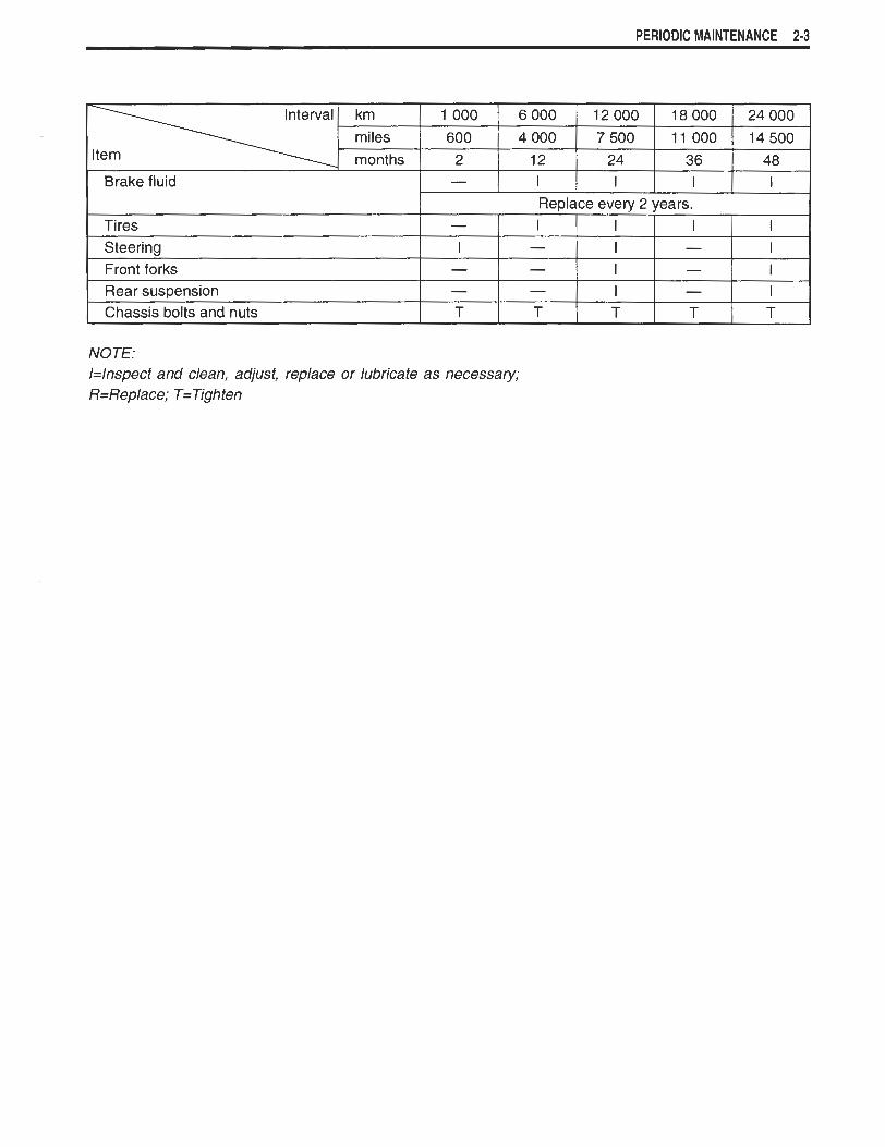
PERIODIC MAINTENANCE 2-3
Interval km
miles
-
1 Chassis bolts and nuts I T I T I T I T I T P I
1 000
600
2
Tires Steering Front forks Rear sus~ension
NOTE: /=Inspect and clean, adjust, replace or lubricate as necessary; R=Replace; T=Tighten
Replace every 2 years. I
6 000
4 000
12
- I - -
I
12000
7 500
24
I - - -
I
18000
11000
36
I
I I I 1
24000
14500
48
I - - -
I I I I

2-4 PERIODIC MAINTENANCE
LUBRICATION POINTS Proper lubrication is important for smooth operation and long life of each working part of the motorcycle. Major lubrication points are indicated below.
@ / Clutch lever holder ( @ I Side-stand pivot I
1 and spring hook I @ I Footrest pivot 1
Brake pedal pivot and footrest pivot
NOTE: * Before lubricating each part, clean off any rusty spots and wipe off any grease, oil, dirt or grime.
Lubricate exposed parts which are subject to rust, with a rust preventative spray whenever the motorcycle has been operated under wet or rainy conditions.
PERIODIC MAINTENANCE 2-5
MAINTENANCE AND TUNE-UP PRO- CEDURES This section describes the servicing procedures for each item of the Periodic Maintenance requirements.
AIR CLEANER
Inspect every 6 000 km (4 000 miles, 12 months) and replace every 18 000 km (1 1 000 miles, 36 months).
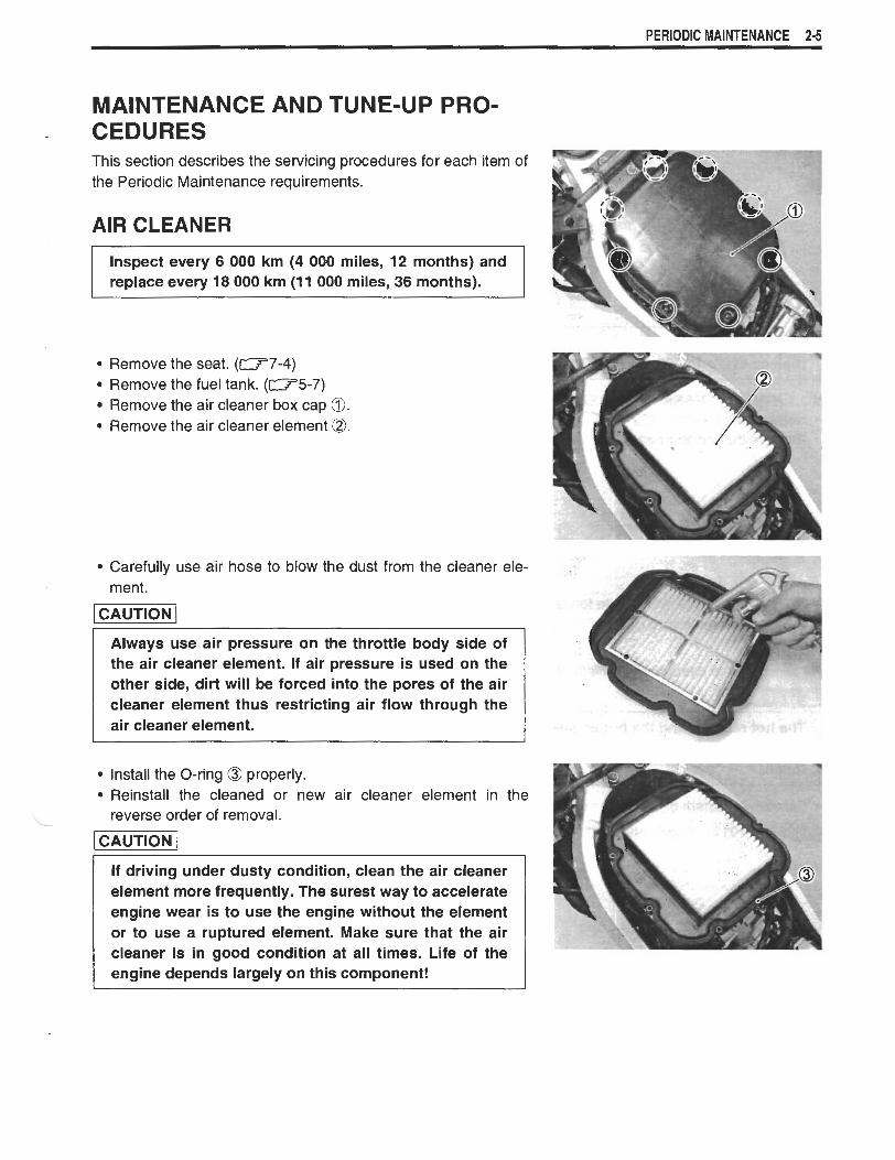
Remove the seat. (W7-4) Remove the fuel tank. (-5-7) Remove the air cleaner box cap 0. Remove the air cleaner element @.
Carefully use air hose to blow the dust from the cleaner ele- ment.
Always use air pressure on the throttle body side of the air cleaner element. If air pressure i s used on the other side, dirt will be forced into the pores of the air cleaner element thus restricting air flow through the air cleaner element.
Install the O-ring @ properly. Reinstall the cleaned or new air cleaner element in the reverse order of removal.
CAUTION I If driving under dusty condition, clean the air cleaner element more frequently. The surest way to accelerate engine wear is to use the engine without the element or to use a ruptured element. Make sure that the air cleaner is in good condition at all times. Life of the engine depends largely on this component!

26 PERIODIC MAINTENANCE
NOTE: When cleaning the air cleaner element, drain water from the air cleaner by removing the drain plug.
SPARK PLUG
Inspect every 6 000 km (4 000 miles, 12 months) and replace every 12 000 km (7 500 miles, 24 months).
NO.l (FRONT) SPARK PLUG REMOVAL Remove the cowling. (-7-5). Remove the radiator mounting bolt a.
Move the radiator lower side to forward. Remove the spark plug cap Q.
NOTE: Be careful not to damage the radiator fins.
The hot radiator and the hot engine can burn you. Wait until the radiator and the engine are cool enough to touch.
Remove the spark plug with the special tool.
m09930-10121: Spark plug socket wrench set
PERIODIC MAINTENANCE 2-7
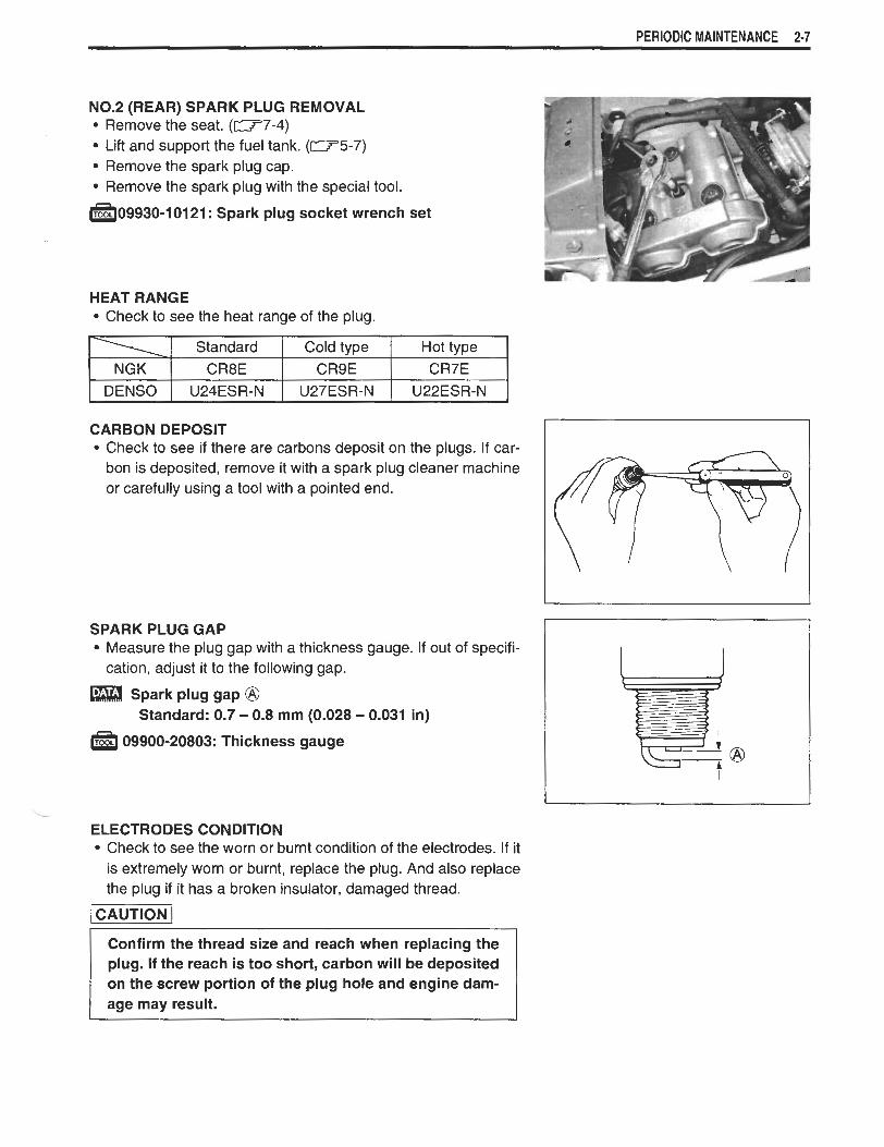
N0.2 (REAR) SPARK PLUG REMOVAL Remove the seat. (-7-4) Lift and support the fuel tank. ( W 5 - 7 ) Remove the spark plug cap. Remove the spark plug with the special tool.
a09930-10121: Spark plug socket wrench set
HEAT RANGE Check to see the heat range of the plug.
I Standard I Cold t v ~ e 1 Hot t v ~ e \ I I - . I * . 1 NGK 1 CR8E CR9E CR7E I
CARBON DEPOSIT Check to see if there are carbons deposit on the plugs. If car- bon is deposited, remove it with a spark plug cleaner machine or carefully using a tool with a pointed end.
SPARK PLUG GAP Measure the plug gap with a thickness gauge. If out of specifi- cation, adjust it to the following gap.
Spark plug gap @ Standard: 0.7 - 0.8 mm (0.028 - 0.031 in)
a 09900-20803: Thickness gauge
--
ELECTRODES CONDITION Check to see the worn or burnt condition of the electrodes. If it is extremely worn or burnt, replace the plug. And also replace the plug if it has a broken insulator, damaged thread.
-1
plug. If the reach is too short, carbon will be deposited on the screw portion of the plug hole and engine dam- age may result.

2-8 PERIODIC MAINTENANCE
SPARK PLUG AND PLUG CAP INSTALLATION
I CAUTION I Before using a spark plug wrench, carefully turn the spark plug by finger into the threads of the cylinder head to prevent damage the aluminum threads.
Install the spark plugs to the cylinder heads by finger tight, and then tighten them to the specified torque.
Spark plug: 11 N-m (1.1 kgf-m, 8.0 Ib-ft)
NOTE: When fitting the spark plug caps, front and rear, face the triangle mark @ on the water-proof cover to each cylinder exhaust side.
VALVE CLEARANCE
I Inspect every 24 000 krn (15 000 miles, 48 months). I Remove the seat. (-7-4) Lift and support the fuel tank. (-5-7) Remove the spark plugs. (-2-6) Remove the cylinder head covers.
The valve clearance specification is exhaust valves.
different for intake and
Valve clearance must be checked and adjusted, 1) at the time of periodic inspection, 2) when the valve mechanism is serviced, and 3) when the camshafts are disturbed by removing them for servicing.
Valve clearance (when cold) IN. : 0.10 - 0.20 mm (0.004 - 0.008 in) EX. : 0.20 - 0.30 mm (0.008 - 0.012 in)
NOTE: * The valve clearance should be taken when each cylinder is at
Top Dead Center (TDC) of compression stroke. * The cams (IN & EX) on the front cylinder at position @ show
the front cylinder at TDC of compression stroke. * The cams (IN & EX) on the rear cylinder at position @$ show
the rear cylinder at TLIC of compression stroke. * The clearance specification is for COLD state. * To turn the crankshaft for clearance checking, be sure to use a
17-mm wrench, and rotate in the normal running direction. All spark plugs should be removed.

PERIODIC MAINTENANCE 2-9
Remove the generator cover plug @ and timing inspection plug 0.
Turn the crankshaft to set the No.1 (Front) cylinder at TDC of compression stroke. (Align the "F I T line on the generator rotor to the index mark of valve timing inspection hole and also bring the camshafts to the position as shown in page 2-8.)
To inspect the No.1 (Front) cylinder valve clearance, use a thickness gauge between the tappet and the cam. If the clear- ance is out of specification, adjust it into the specified range.
09900-20803: Thickness gauge
Turn the crankshaft 270 degrees (314 turns) to set the No.2 (Rear) cylinder at TDC of compression stroke. (Align the "R I T' line on the generator rotor to the index mark of valve timing inspection hole and also bring the camshafts to the position as shown in page 2-8.)
Inspect the No.2 (Rear) cylinder valve clearance as the same manner of No.1 (Front) cylinder and adjust the clearance if necessary.
-09900-20803: Thickness gauge
2-10 PERIODIC MAINTENANCE
VALVE CLEARANCE ADJUSTMENT The clearance is adjusted by replacing the existing tappet shim by a thicker or thinner shim.
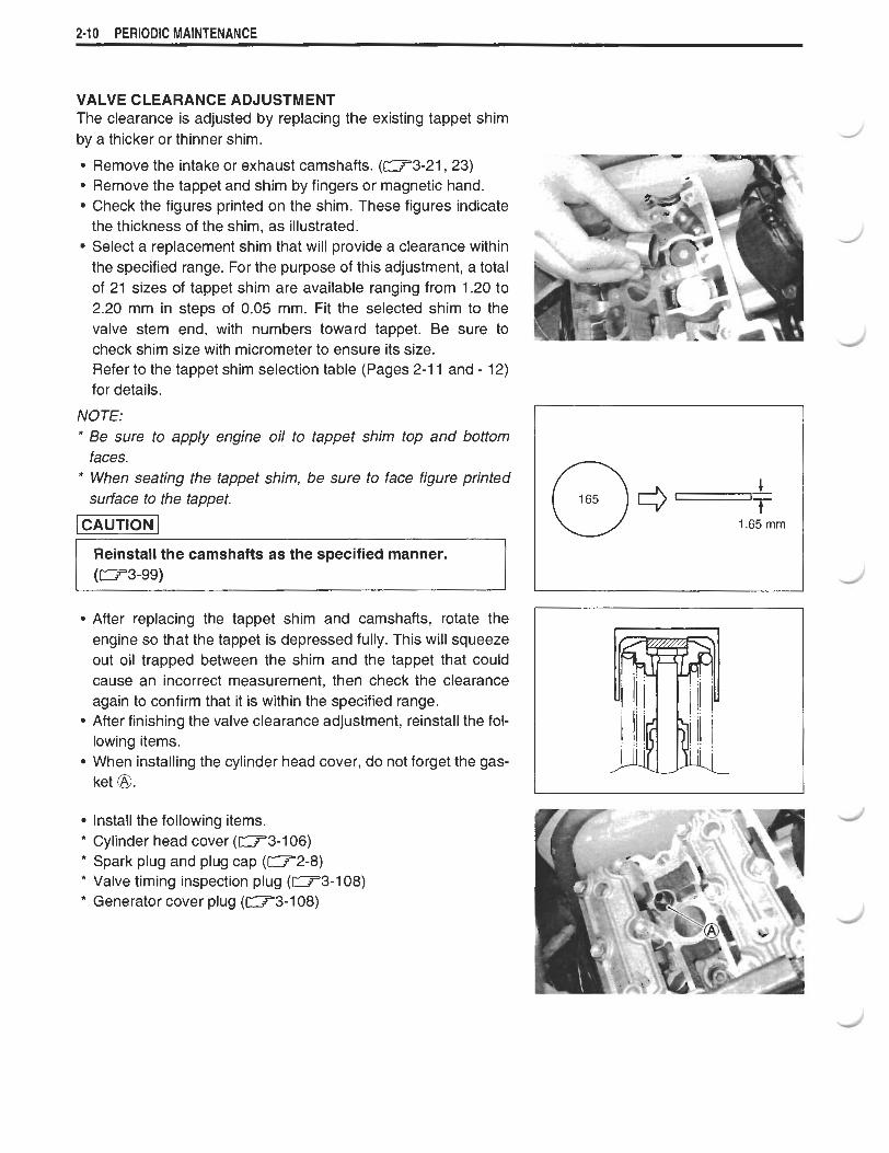
Remove the intake or exhaust camshafts. (W3-21,23) Remove the tappet and shim by fingers or magnetic hand. Check the figures printed on the shim. These figures indicate the thickness of the shim, as illustrated. Select a replacement shim that will provide a clearance within the specified range. For the purpose of this adjustment, a total of 21 sizes of tappet shim are available ranging from 1.20 to 2.20 mm in steps of 0.05 mm. Fit the selected shim to the valve stem end, with numbers toward tappet. Be sure to check shim size with micrometer to ensure its size. Refer to the tappet shim selection table (Pages 2-1 1 and - 12) for details.
NOTE: * Be sure to apply engine oil to tappet shim top and bottom
faces. * When seating the tappet shim, be sure to face figure printed
surface to the tappet.
piiimiq Reinstall the camshafts as the specified manner. (W3-99)
After replacing the tappet shim and camshafts, rotate the engine so that the tappet is depressed fully. This will squeeze out oil trapped between the shim and the tappet that could cause an incorrect measurement, then check the clearance again to confirm that it is within the specified range. After finishing the valve clearance adjustment, reinstall the fol- lowing items. When installing the cylinder head cover, do not forget the gas- ket @.
Install the following items. * Cylinder head cover (-3-106) * Spark plug and plug cap (-2-8) * Valve timing inspection plug (-3-1 08) * Generator cover plug (W3-108)
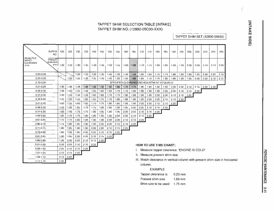
TAPPET SHlM SELECTION TABLE [INTAKE] TAPPET SHlM NO. (1 2892-05C00-XXX)
I TAPPET SHlM SET (1 2800-05830) I
HOW TO USE THIS CHART:
I. Measure tappet clearance. "ENGINE IS COLD"
It. Measure present shim size.
Ill. Match clearance in vertical column with present shim size in horizontal
column.
EXAMPLE
Tappet clearance is 0.23 mm
Present shim size 1.65 mm
Shim size to be used 1.75 mm

TAPPET SHlM SELECTION TABLE [EXHAUST] TAPPET SHl M NO. (1 2892-05C00-XXX)
TAPPET SHlM SET (1 2800-05830)
SUFFIX 120 125 130 135 !40 145 150 155 160 ?55 170 175 180 185 190 195 200 205 210 215 220
1.20 1.25 1.30 1.35 1.40 1.45 1.50 1.55 1.60 1.65 1.70 1.75 1.80 1.85 1.90 1.95 2.00 2.05 2.10 2.15 2.20
0.05-0.09 \ 1.20 1.25 1.30 1.35 1.40 1.45 1.50 1.55 1.60 1.65 1.70 1.75 1.80 1.85 1.90 1.95 2.00 2.05
HOW TO USE THIS CHART:
I. Measure tappet clearance. "ENGINE IS COLD"
II. Measure present shim size. Ill. Match clearance in vertical column with present shim size in horizontal
column. EXAMPLE
Tappet clearance is 0.33 mm
Present shim size 1.65 mm Shim size to be used 1.75 mm
PERIODIC MAINTENANCE 2-13
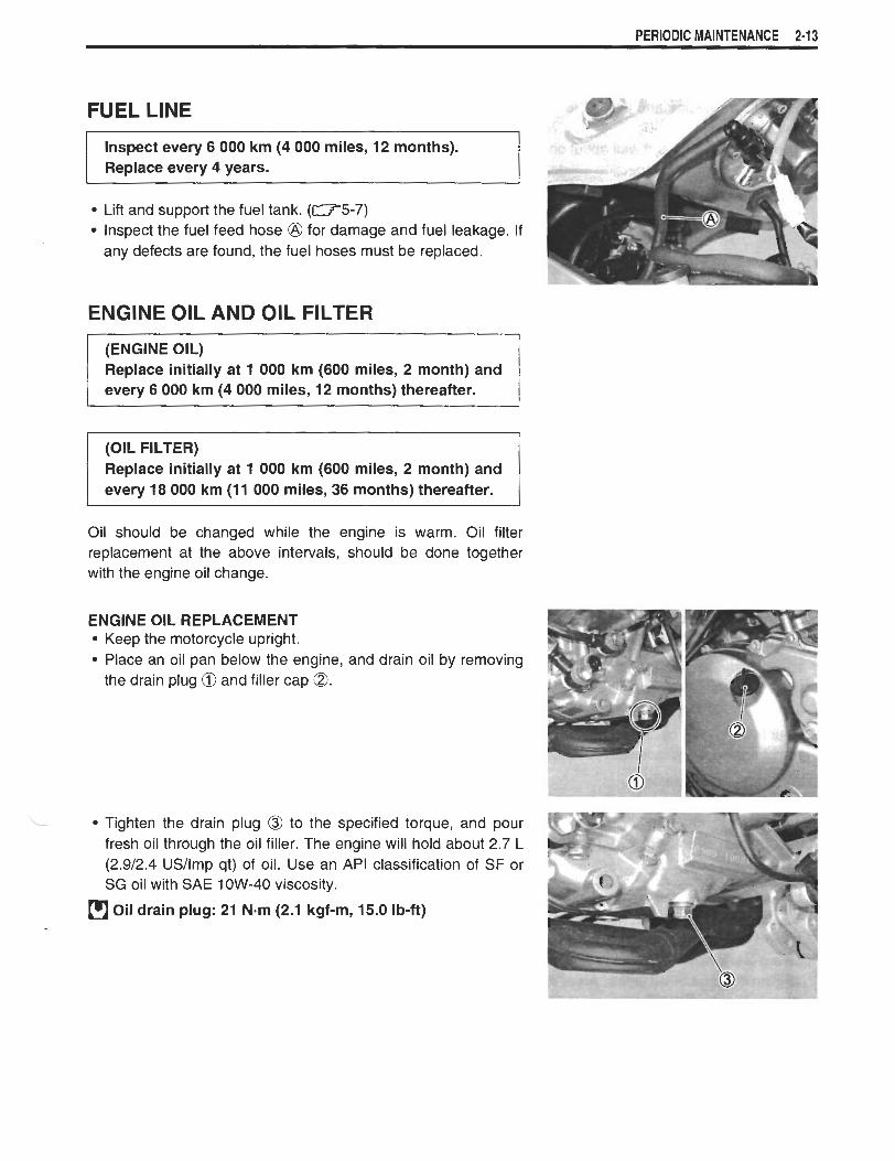
FUEL LINE
lnspect every 6 000 km (4 000 miles, 12 months). Replace every 4 years.
Lift and support the fuel tank. (-5-7) Inspect the fuel feed hose @ for damage and fuel leakage. If any defects are found, the fuel hoses must be replaced.
ENGINE OIL AND OIL FILTER
(ENGINE OIL) Replace initially at 1 000 km (600 miles, 2 month) and every 6 000 km (4 000 miles, 12 months) thereafter.
- - -
(OIL FILTER) Replace initially at 1 000 km (600 miles, 2 month) and every 18 000 km (1 1 000 miles, 36 months) thereafter.
Oil should be changed while the engine is warm. Oil filter replacement at the above intervals, should be done together with the engine oil change.
ENGINE OIL REPLACEMENT Keep the motorcycle upright. Place an oil pan below the engine, and drain oil by removing the drain plug @ and filler cap 0.
- Tighten the drain plug @ to the specified torque, and pour fresh oil through the oil filler. The engine will hold about 2.7 L (2.912.4 USIlmp qt) of oil. Use an API classification of SF or SG oil with SAE 1 OW-40 viscosity.
Oil drain plug: 21 N-m (2.1 kgf-m, 15.0 Ib-ft)

2-14 PERIODIC MAINTENANCE
Start up the engine and allow it to run for several minutes at idling speed. Turn off the engine and wait about one minute, then check the oil level through the inspection window @. If the level is below mark "L", add oil to " F level. If the level is above mark "F, drain oil to "F" level.
OIL FILTER REPLACEMENT Drain engine oil in the same manner of engine oil replacement procedure. Remove the oil filter @ with the special tool.
-09915-40610: Oil filter wrench
Apply engine oil lightly to the gasket of the new filter a before installation. Install the new filter turning it by hand until you feel that the fil- ter gasket contacts the mounting surface. Then tighten it 2 turns with the special tool.
09915-40610: Oil filter wrench
NOTE: To properly tighten the filter, use the special tool. Never tighten the filter by hand.
* Afler contcting the gasket, tighten 2 turns.
Pour fresh engine oil and check the oil level in the same man- ner of engine oil replacement procedure.
Engine oil capacity Oil change: 2.3 L (2.412.0 USIlmp qt) Filter change: 2.7 L (2.912.4 USllmp qt) Engine overhaul: 3.1 L (3.312.7 USllmp qt)
ONLY USE A GENUINE SUZUKl MOTORCYCLE OIL FILTER. Other manufacturer's oil filters may differ in thread specifications (thread diameter and pitch), fil- tering performance and durability which may lead to engine damage or oil leaks. Also, do not use a genuine Suzuki automobile oil filter on this motorcycle.

PERIODIC MAINTENANCE 2-15
ENGINE IDLE SPEED
lnspect initially at 1 000 km (600 miles, 2 month) and every 6 000 km (4 000 miles, 12 months) thereafter.
NOTE: Make this adjustment when the engine is hot.
Start up the engine and set its idle speed to the specified range by turning the throttle stop screw a.
Engine idle speed: 1 300 * 100 rlmin
THROTTLE CABLE PLAY
lnspect initially at 1 000 km (600 miles, 2 month) and every 6 000 km (4 000 miles, 12 months) thereafter.
Adjust the throttle cable play @ with the following three steps.
MINOR ADJUSTMENT First step:
Remove the cable adjuster covers a. Loosen the lock-nut @ of the throttle returning cable @ and turn in the adjuster @ fully into the threads.
Second step: Loosen the lock-nut @ of the throttle pulling cable @. Turn the adjuster in or out until the throttle cable play @ should be 2.0 - 4.0 mm (0.08 - 0.16 in) at the throttle grip. Tighten the lock-nut @ while holding the adjuster O.
Third step: While holding the throttle grip at the fully closed position, slowly turn out the adjuster @ of the throttle returning cable @ to feel resistance. Tighten the lock-nut @ while holding the adjuster @.
Throttle cable play @: 2.0 - 4.0 mm (0.08 - 0.16 in)
After the adjustment is completed, check that handle- bar movement does not raise the engine idle speed and that the throttle grip returns smoothly and auto-
NOTE: Major adjustment can be made by the throttle body side adjuster.

2-16 PERIODIC MAINTENANCE
MAJOR ADJUSTMENT Remove the fuel tank. (-5-7) Remove the air cleaner box. (-5-1 5) Loosen the lock-nut @ of the throttle returning cable. Turn the returning cable adjuster to obtain proper cable
play. Loosen the lock-nut @ of the throttle pulling cable. Turn the pulling cable adjuster @ in or out until the throttle cable play @ should be 2.0 - 4.0 mm (0.08 - 0.16 in) at the throttle grip. Tighten the lock-nut @ securely while holding the adjuster @.
Throttle cable play @I: 2.0 - 4.0 mm (0.08 - 0.16 in)
While holding the throttle grip at the fully closed position, slowly turn the returning cable adjuster @ to obtain a slack of 1.0 mm (0.04 in). Tighten the lock-nut @ securely.
After the adjustment is completed, check that handle- bar movement does not raise the engine idle speed and that the throttle grip returns smoothly and auto- matically.
THROTTLE VALVE SYNCHRONIZATION
lnspect initially at 1 000 km (600 miles, 2 months) (E-33 only) and every 12 000 km (7 500 miles, 24 months).
lnspect the throttle valve synchronization periodically. (-5-32)
EVAPORATIVE EMISSION CONTROL SYS- TEM (E-33 ONLY)
lnspect every 12 000 km (7 500 miles, 24 months). Replace vapor hose every 4 years.
lnspect the evaporative emission control system periodically.
PAlR (AIR SUPPLY) SYSTEM
I lnspect every 12 000 krn (7 500 miles, 24 months). ( lnspect the PAIR (air supply) system periodically. (-10-6)
PERIODIC MAINTENANCE 2-17
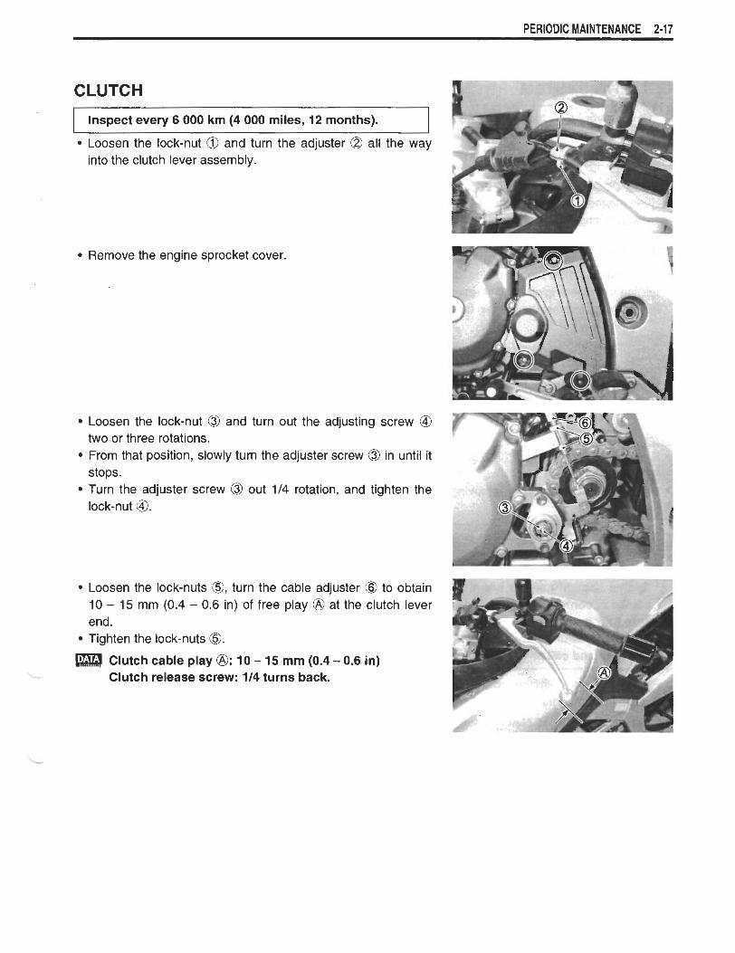
CLUTCH
Inspect every 6 000 km (4 000 miles, 12 months).
Loosen the lock-nut @ and turn the adjuster @ all the way into the clutch lever assembly.
Remove the engine sprocket cover.
Loosen the lock-nut @ and turn out the adjusting screw @ =T- *?%a r- - two or three rotations. From that position, slowly turn the adjuster screw @ in until it stops. Turn the adjuster screw @ out 114 rotation, and tighten the lock-nut @. C
I
Loosen the lock-nuts 0, turn the cable adjuster 10 - 15 mm (0.4 - 0.6 in) of free play @ at the end. Tighten the lock-nuts 0.
Clutch cable play @: 10 - 15 mm (0.4 - 0.6 -. Clutch release screw: 114 turns back.
@ to obtain clutch lever
in)

2-18 PERIODIC MAINTENANCE
COOLING SYSTEM
Inspect every 6 000 km (4 000 miles, 12 months). Replace engine coolant every 2 years. Replace radiator hoses every 4 years.
ENGINE COOLANT LEVEL CHECK Keep the motorcycle upright. Check the engine coolant level by observing the full and lower lines on the engine coolant reserve tank. @ Full line @ Lower line
If the level is below the lower line, add engine coolant to the full line from the engine coolant reserve tank filler. To remove the filler cap, remove the left fuel tank side cover. (-7-4)
ENGINE COOLANT CHANGE Remove the left cowling. (-7-5) Remove the radiator cap 0. Drain the engine coolant by removing the drain bolt @.
* Do not open the radiator cap when the engine is hot, as you may be injured by escaping hot liquid or vapor.
* Engine coolant may be harmful if swallowed or if it comes in contact with skin or eyes. If engine coolant gets into the eyes or in contact with the skin, flush thoroughly with plenty of water. If swallowed, induce vomiting and call physician immediately!
Flush the radiator with fresh water if necessary. Tighten the water drain bolt @ to the specified torque.
Water drain bolt: 13 N-m (1.3 kgf-m, 9.5 Ib-ft)
Pour the specified engine coolant up to the radiator inlet. Bleed the air from the engine coolant circuit as following pro- cedure.
NOTE: For engine coolant information, refer to page 6-2.

PERIODIC MAINTENANCE 2-19
v - AIR BLEEDING THE COOLING CIRCUIT
Add engine coolant up to the radiator inlet. Support the motorcycle upright. Slowly swing the motorcycle, right and left, to bleed the air trapped in the cooling circuit. Add engine coolant up to the radiator inlet.
Start up the engine and bleed air from the radiator inlet com- pletely. Lightly tap the thermostat case @ and slowly swing the motor- " cycle, right and left, to bleed the air trapped in the thermostat case O.
P Add engine coolant up to the radiator inlet. Repeat the above procedure until bleed no air from the radia- tor inlet. l
Close the radiator cap @ securely. After warming up and cooling down the engine several times, add the engine coolant up to the full level of the reserve tank. Install the cowling. ( W 7 - 8 )
I Repeat the above procedure several times and make I sure that the radiator is filled with engine coolant up to the reserve tank full level.
a Engine coolant capacity Reverse tank side: 250 ml(0.5310.44 USnmp qt) Engine side: 1 650 ml (3.4912.90 USllmp qt)
2-20 PERIODIC MAINTENANCE
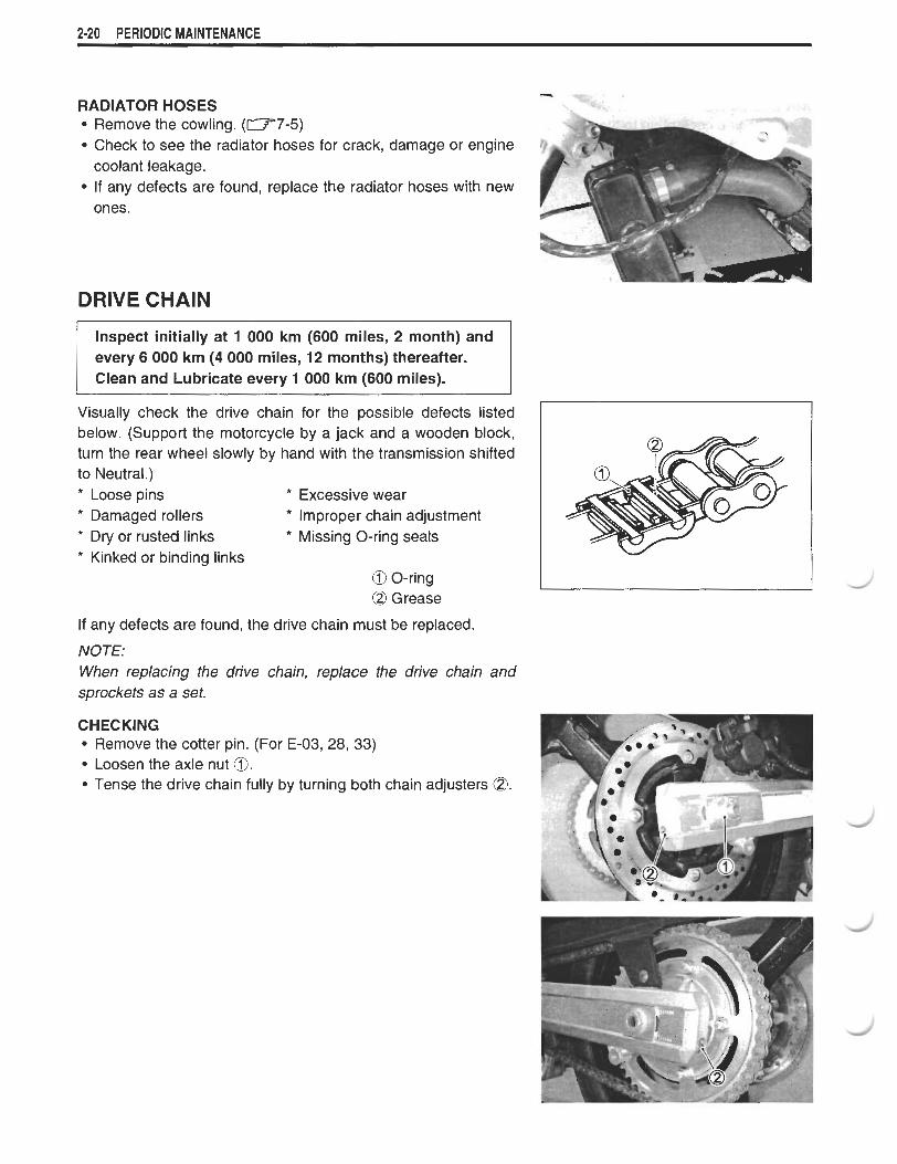
RADIATOR HOSES Remove the cowling. (-7-5) Check to see the radiator hoses for crack, damage or engine coolant leakage. If any defects are found, replace the radiator hoses with new ones.
DRIVE CHAIN
Inspect initially at 1 000 km (600 miles, 2 month) and every 6 000 km (4 000 miles, 12 months) thereafter. Clean and Lubricate every 1 000 km (600 miles).
Visually check the drive chain for the possible defects listed below. (Support the motorcycle by a jack and a wooden block, turn the rear wheel slowly by hand with the transmission shifted to Neutral.) * Loose pins Excessive wear * Damaged rollers * Improper chain adjustment * Dry or rusted links * Missing O-ring seals
Kinked or binding links O O-ring O Grease
If any defects are found, the drive chain must be replaced.
NOTE: When replacing the drive chain, replace the drive chain and sprockets as a set.
CHECKING Remove the cotter pin. (For E-03,28, 33) Loosen the axle nut 0. Tense the drive chain fully by turning both chain adjusters @.
PERIODIC MAINTENANCE 2-21
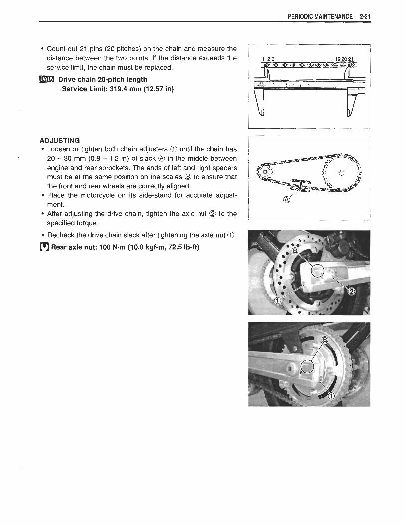
Count out 21 pins (20 pitches) on the chain and measure the distance between the two points. If the distance exceeds the service limit, the chain must be replaced.
Drive chain 20-pitch length Service Limit: 319.4 rnrn (12.57 in)
ADJUSTING Loosen or tighten both chain adjusters @ until the chain has 20 - 30 mm (0.8 - 1.2 in) of slack @ in the middle between engine and rear sprockets. The ends of left and right spacers must be at the same position on the scales (g) to ensure that the front and rear wheels are correctly aligned. Place the motorcycle on its side-stand for accurate adjust- ment. After adjusting the drive chain, tighten the axle nut @ to the specified torque.
Recheck the drive chain slack after tightening the axle nut 0. Rear axle nut: 100 N-rn (10.0 kgf-rn, 72.5 Ib-ft)
2-22 PERIODIC MAINTENANCE
CLEANING AND LUBRICATING Wash the chain with kerosene. If the chain tends to rust quickly, the intervals must be shortened.
Do not use trichlene, gasoline or any similar fluids: These fluids have too great a dissolving power for this chain and, what is more important, they can damage the "0"-rings (or seals) confining the grease in the bush to pin clearance. Remember, high durability comes from the presence of grease in that clearance.
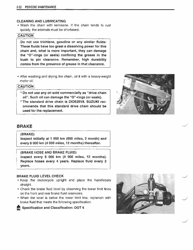
After washing and drying the chain, oil it with a heavy-weight motor oil.
-1 - -
Do not use any oil sold commercially as "drive chain oil". Such oil can damage the "On-rings (or seals).
* The standard drive chain is DID525V8. SUZUKl rec- ommends that this standard drive chain should be used for the replacement.
BRAKE
(BRAKE) lnspect initially at 1 000 km (600 miles, 2 month) and every 6 000 km (4 000 miles, 12 months) thereafter.
- - --
(BRAKE HOSE AND BRAKE FLUID) Inspect every 6 000 km (4 000 miles, 12 months). Replace hoses every 4 years. Replace fluid every 2 years. I
BRAKE FLUID LEVEL CHECK Keep the motorcycle upright and place the handlebars straight. Check the brake fluid level by observing the lower limit lines on the front and rear brake fluid reservoirs. When the level is below the lower limit line, replenish with brake fluid that meets the following specification.
Specification and Classification: DOT 4

PERIODIC MAINTENANCE 2-23
The brake system of this motorcycle is filled with a glycol-based brake fluid. Do not use or mix different types of fluid such as silicone-based or petro- leum-based. Do not use any brake fluid taken from old, used or unsealed containers. Never re-use brake fluid left over from the last servicing or stored for a long period.
Brake fluid, if it leaks, will interfere with safe running and immediately discolor painted surfaces. Check the brake hoses and hose joints for cracks and oil leakage before riding.
BRAKE PADS
Remove the brake caliper. (Front) The extent of brake pad wear can be checked by observing the grooved limit @ on the pad. When the wear exceeds the grooved limit, replace the pads with the new ones. ( W 7 - 5 9 and - 69)
-1 Replace the brake pad as a set, otherwise braking per- formance will be adversely affected.
2-24 PERIODIC MAINTENANCE
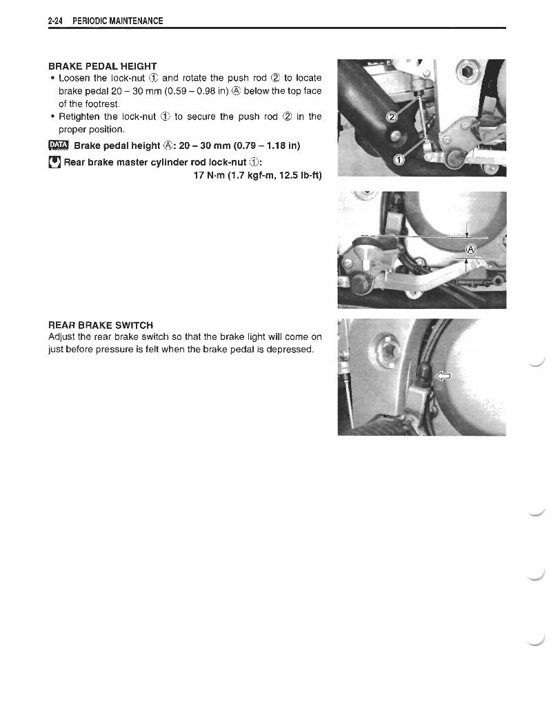
BRAKE PEDAL HEIGHT Loosen the lock-nut @ and rotate the push rod a to locate brake pedal 20 - 30 mm (0.59 - 0.98 in) @ below the top face of the footrest. Retighten the lock-nut @ to secure the push rod a in the proper position.
Brake pedal height @: 20 - 30 mm (0.79 - 1 . I8 in)
Rear brake master cylinder rod lock-nut 0: 17 N-rn (1.7 kgf-m, 12.5 Ib-ft)
REAR BRAKE SWITCH Adjust the rear brake switch so that the brake light will come on just before pressure is felt when the brake pedal is depressed.
e
E :: xitan tan
PERIODIC MAINTENANCE 2-25
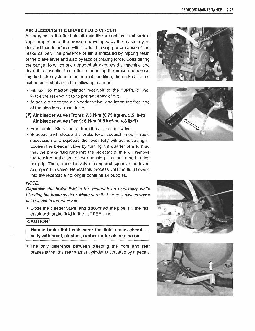
AIR BLEEDING THE BRAKE FLUID CIRCUIT Air trapped in the fluid circuit acts like a cushion to absorb a large proportion of the pressure developed by the master cylin- der and thus interferes with the full braking performance of the brake caliper. The presence of air is indicated by "sponginess" of the brake lever and also by lack of braking force. Considering the danger to which such trapped air exposes the machine and rider, it is essential that, after remounting the brake and restor- ing the brake system to the normal condition, the brake fluid cir- cuit be purged of air in the following manner:
Fill up the master cylinder reservoir to the "UPPER" line. Place the reservoir cap to prevent entry of dirt. Attach a pipe to the air bleeder valve, and insert the free end of the pipe into a receptacle.
fl Air bleeder valve (Front): 7.5 N-m (0.75 kgf-m, 5.5 Ib-ft) Air bleeder valve (Rear): 6 N-m (0.6 kgf-m, 4.3 Ib-ft)
Front brake: Bleed the air from the air bleeder valve. Squeeze and release the brake lever several times in rapid succession and squeeze the lever fully without releasing it. Loosen the bleeder valve by turning it a quarter of a turn so that the brake fluid runs into the receptacle; this will remove the tension of the brake lever causing it to touch the handle- bar grip. Then, close the valve, pump and squeeze the lever, and open the valve. Repeat this process until the fluid flowing into the receptacle no longer contains air bubbles.
NOTE: Replenish the brake fluid in the reservoir as necessary while bleeding the brake system. Make sure that there is always some fluid visible in the reservoir.
Close the bleeder valve, and disconnect the pipe. Fill the res- ervoir with brake fluid to the "UPPER" line.
Handle brake fluid with care: the fluid reacts chemi- cally with paint, plastics, rubber materials and so on.
The only difference between bleeding the front and rear brakes is that the rear master cylinder is actuated by a pedal.

2-26 PERIODIC MAINTENANCE
TlRE
I Inspect every 6 000 km (4 000 miles, 12 months). I TlRE TREAD CONDITION Operating the motorcycle with excessively worn tires will decrease riding stability and consequently invite a dangerous situation. It is highly recommended to replace a tire when the remaining depth of tire tread reaches the following specification.
09900-20805: Tire depth gauge
Tire tread depth Service Limit (FRONT) : 1.6 mm (0.06 in)
(REAR) : 2.0 mm (0.08 in)
TlRE PRESSURE If the tire pressure is too high or too low, steering will be adversely affected and tire wear increased. Therefore, maintain the correct tire pressure for good roadability or shorter tire life will result. Cold inflation tire pressure is as follows.
I COLD INFLATION I SOLO RlNDlNG 1 DUAL RIDING I
I FRONT 1 225 1 2.25 1 33 1 225 1 2.25 1 33 1
- --- . - -
TlRE PRESSURE
I L I
I REAR 1250 1 2.50 1 36 1 280 1 2.80 1 41
The standard tire fitted on this motorcycle is 110180 R19MlC (59H) for front and 150170 R17MlC (69H) for
I
kPa I kgf/cmz I psi I kPa I kgf/cm2 I psi
rear. The use of tires other than those specified may cause instability. It is highly recommended to use a SUZUKl Genuine Tire.
TlRE TYPE BRIDGESTONE (Front : TW101F Rear : TW152F)
STEERING
lnspect initially at 1 000 km (600 miles, 2 month) and every 12 000 km (7 500 miles, 24 months) thereafter.
Steering should be adjusted properly for smooth turning of han- dlebars and safe running. Overtight steering prevents smooth turning of the handlebars and too loose steering will cause poor stability. Check that there is no play in the steering stem while grasping the lower fork tubes by supporting the machine so that the front wheel is off the ground, with the wheel straight ahead, and pull forward. If play is found, perform steering bearing adjustment as described in page 7-31 of this manual.

PERIODIC MAINTENANCE 2-27
FRONT FORK
lnspect every 12 000 km (7 500 miles, 12 months).
lnspect the front forks for oil leakage, scoring or scratches on the outer surface of the inner tubes. Replace any defective parts, if necessary. (W7-17)
REAR SUSPENSION
I lnspect every 12 000 km (7 500 miles, 12 months). I lnspect the damper for oil leakage and the spring unit for dam- age. Check that there is no play in the swingarm assembly. Replace any defective parts, if necessary. (W7-45)
EXHAUST PIPE BOLT
Tighten initially at 1 000 km (600 miles, 2 month) and every 6 000 km (4 000 miles, 12 months) thereafter.
Tighten the exhaust pipe bolts and muffler mounting bolts to
- the specified torque.
Muffler mounting bolt h u t @: 23 N-m (2.3 kgf-m, 16.5 Ib-ft) Exhaust pipe bolt @loo: 23 N-m (2.3 kgf-m, 16.5 Ib-ft)
a 99000-32050: THREAD LOCK "1 342"
EXHAUST GAS SEALER: PERMATEX 1372
2-28 PERIODIC MAINTENANCE
CHASSIS BOLT AND NUT - - -- -
Tighten initially at 1 000 km (600 miles, 2 month) and miles, 12 months) thereafter.
Check that all chassis bolts and nuts are tightened to their specified torque. (Refer to page 2-29 for the loca- tions of the following nuts and bolts on the motorcycle.)
ITEM I ~ . m I kgf-m I I b-ft 1 @ Steering stem head nut I 90 1 9.0 1 65.0 I
@ Front axle I 65 I 6.5 I 47.0 I
a Steering stem lock-nut 0 Front fork upper clamp bolt @ Front fork lower clamp bolt
I @ Front axle pinch bolt I 23 I 2.3 1 16.5 I
80 23 23
I Air bleeder valve (Rear) 1 6 I 0.6 1 4.3 I
Handlebar clamp bolt @ Front brake master cylinder mounting bolt
@ Front brake caliper mounting bolt 0 Brake hose union bolt @ Air bleeder valve (Front)
8.0 2.3 2.3
10 Front footrest bracket mountinq bolt I 25 1 2.5 I 18.0 I
58.0 16.5 16.5
23
10 39 23 7.5
@ Brake disc bolt (Front & Rear) @ Rear brake caliper mounting bolt
@ Rear brake master cylinder mounting bolt @ Rear brake master cvlinder rod lock-nut
1 @ Swingarm pivot nut I 100 I 10.0 I 72.5 I I Swingarm pivot lock-nut 90 9.0 65.0
2.3 1 .O 3.9 2.3 0.75
23 22 10 18
(a Rear shock absorber mounting nut IUmer & Lower)
16.5 7.0
28.0 16.5 5.5
2.3 2.2
1 .O 1.8
-
7 I @seat rail mounting bolt 1 50 5.0 1 36.0 I
16.5 16.0
7.0 13.0
, - I I- -
@I Cusion lever nut Cusion rod nut
I Rear axle nut
78
78
100
7.8 7.8 10.0
56.5 56.5
72.5

PERIODIC MAINTENANCE 2-29
2-30 PERIODIC MAINTENANCE
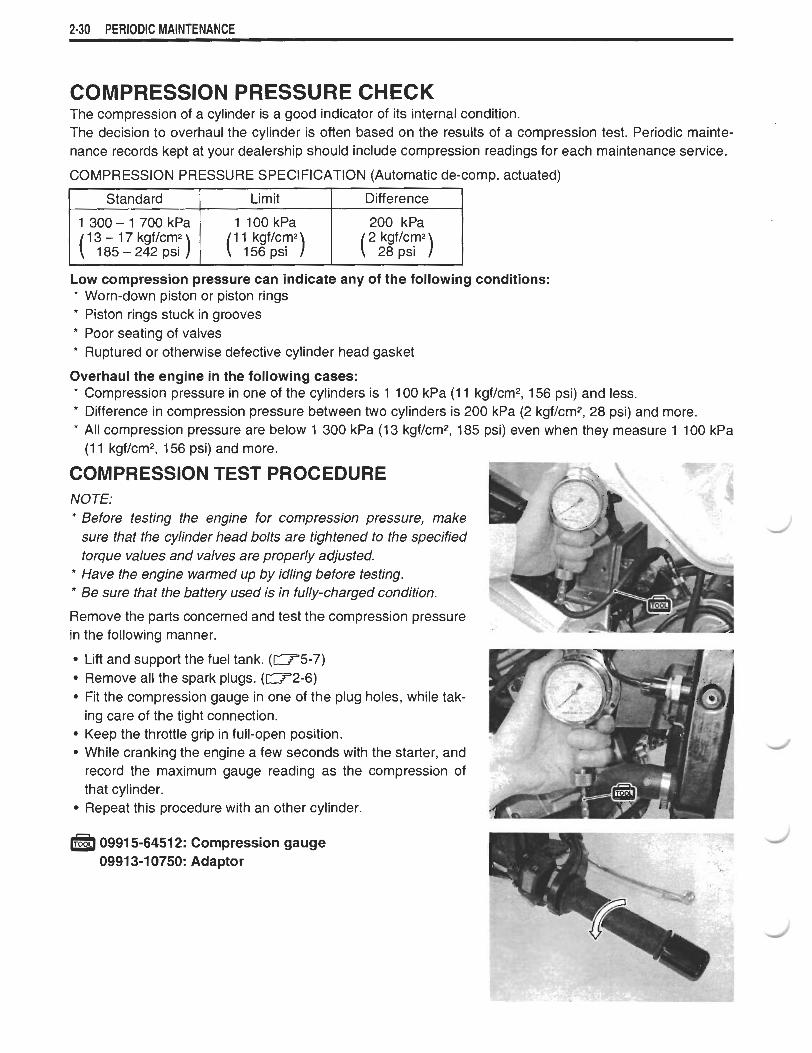
COMPRESSION PRESSURE CHECK The compression of a cylinder is a good indicator of its internal condition. The decision to overhaul the cylinder is often based on the results of a compression test. Periodic mainte- nance records kept at your dealership should include compression readings for each maintenance service.
COMPRESSION PRESSURE SPECIFICATION (Automatic de-comp. actuated)
Low compression pressure can indicate any of the following conditions: * Worn-down piston or piston rings * Piston rings stuck in grooves * Poor seating of valves * Ruptured or otherwise defective cylinder head gasket
Overhaul the engine in the following cases: * Compression pressure in one of the cylinders is 1 100 kPa (1 1 kgf/cm2, 156 psi) and less. * Difference in compression pressure between two cylinders is 200 kPa (2 kgf/cm2, 28 psi) and more. * All compression pressure are below 1 300 kPa (13 kgf/cm2, 185 psi) even when they measure 1 100 kPa
(1 1 kgfIcm2, 156 psi) and more.
COMPRESSION TEST PROCEDURE NOTE: * Before testing the engine for compression pressure, make
sure that the cylinder head bolts are tightened to the specified torque values and valves are properly adjusted.
* Have the engine warmed up by idling before testing. * Be sure that the battery used is in fully-charged condition.
Remove the parts concerned and test the compression pressure in the following manner.
Lift and support the fuel tank. ( W 5 - 7 ) Remove all the spark plugs. (-2-6) Fit the compression gauge in one of the plug holes, while tak- ing care of the tight connection. Keep the throttle grip in full-open position. While cranking the engine a few seconds with the starter, and record the maximum gauge reading as the compression of that cylinder. Repeat this procedure with an other cylinder.
a 0991 5-6451 2: Compression gauge 0991 3-1 0750: Adaptor

PERIODIC MAINTENANCE 2-31
OIL PRESSURE CHECK Check periodically the oil pressure in the engine to judge roughly the condition of the moving parts.
OIL PRESSURE SPECIFICATION
Above 100 kPa (1.0 kgf/cm2, 14 psi) I Below 400 kPa (4.0 kgflcm2, 57 poi) at 3 000 rlmin., Oil temp. at 60 OC (140 OF)
If the oil pressure is lower or higher than the specification, the following causes may be considered.
LOW OIL PRESSURE * Clogged oil filter * Oil leakage from the oil passage way * Damaged O-ring * Defective oil pump * Combination of the above items
HIGH OIL PRESSURE * Used of high viscosity engine oil * Clogged oil passage way * Combination of the above items
OIL PRESSURE TEST PROCEDURE Start the engine and check if the oil pressure indicator light is turned on. If it keeps on lighting, check the oil pressure indicator light circuit. If it is in good condition, check the oil pressure in the following manner.
Remove the main oil gallery plug @. Install the oil pressure gauge with attachment in the position shown in the figure.
Warm up the engine as follows: Summer 10 min. at 2 000 rlmin. Winter 20 min. at 2 000 rlmin. After warming up, increase the engine speed to 3 000 rlmin. (with the engine tachometer), and read the oil pressure gauge.
0991 5-74521 : Oil pressure gauge hose 09915-74532: Oil pressure gauge attachment 09915-77331 : Meter (for high pressure)
[rJ Main oil gallery plug [M 81: 18 N m (1.8 kgf-m, 13.0 Ib-ft)


![Jan Beutel, ETH Zurich - Welcome - TIK...[B. Jelk] High‐resolution TimelapsePhotography 2009 C2 2010 C2 2011 C2 2012 C2 2013 C2 2014 C2 18.05.2015 C2 19.05.2015 C2 29.05.2015 C2](https://static.fdocuments.in/doc/165x107/60110b99540db573571546c3/jan-beutel-eth-zurich-welcome-tik-b-jelk-higharesolution-timelapsephotography.jpg)