DK32 - DK34 - DK37 - Instrumart · DK32 - DK34 - DK37 Technical Datasheet ... Min. power supply for...
24
DK32 - DK34 - DK37 DK32 - DK34 - DK37 DK32 - DK34 - DK37 DK32 - DK34 - DK37 Technical Datasheet Technical Datasheet Technical Datasheet Technical Datasheet Variable area flowmeter • Robust construction for extreme operating conditions • Local indication without auxiliary power • High pressure and temperature durability © KROHNE 07/2009 - 4000282603 TD DK32-34-37-R04-en
Transcript of DK32 - DK34 - DK37 - Instrumart · DK32 - DK34 - DK37 Technical Datasheet ... Min. power supply for...

DK32 - DK34 - DK37DK32 - DK34 - DK37DK32 - DK34 - DK37DK32 - DK34 - DK37 Technical DatasheetTechnical DatasheetTechnical DatasheetTechnical Datasheet
Variable area flowmeter
• Robust construction for extreme operating conditions• Local indication without auxiliary power• High pressure and temperature durability
© KROHNE 07/2009 - 4000282603 TD DK32-34-37-R04-en
TD_DK32_34_37_R04_en_PRT.book Page 1 Monday, July 27, 2009 10:05 AM

CONTENTS
2 www.krohne.com 07/2009 - 4000282603 TD DK32-34-37-R04-en
DK32 - DK34 - DK37
1 Product features 3
1.1 Flowmeter solutions in an all-metal design.................................................................... 31.2 Variable-area flowmeters of the type DK metal .............................................................. 41.3 Operating principle........................................................................................................... 6
2 Technical data 7
2.1 Technical data................................................................................................................... 72.2 Dimensions ..................................................................................................................... 102.3 Flow table ....................................................................................................................... 132.4 Differential pressure regulators.................................................................................... 15
3 Installation 18
3.1 Intended use ................................................................................................................... 183.2 Installation requirements .............................................................................................. 18
4 Electrical connections 19
4.1 Electrical connection of limit switches .......................................................................... 194.2 DK37/M8M limit switches............................................................................................... 204.3 DK37/M8E electrical signal output ................................................................................ 21
4.3.1 Power supply......................................................................................................................... 224.3.2 Load for HART® communication .......................................................................................... 224.3.3 Parametrization .................................................................................................................... 22
5 Order form 23
TD_DK32_34_37_R04_en_PRT.book Page 2 Monday, July 27, 2009 10:05 AM
PRODUCT FEATURES 1
3
DK32 - DK34 - DK37
www.krohne.com07/2009 - 4000282603 TD DK32-34-37-R04-en
Product features
1.1 Flowmeter solutions in an all-metal design
Solid metal DK flowmeters are suitable for measuring the flow rate of liquids, gases and vapors. Because of their robust design the flowmeters are particularly suited for difficult operating and environmental conditions.
Highlights• DK32 with horizontal connections - with valve• DK34 with vertical connections - without valve• DK37 with an increased measurement accuracy and larger indication• Narrow design enabling a high packing density• Simple installation and start-up
Industries• Chemical• Heating, cooling, and air conditioning• Iron, Steel & Metal• Electronics• Oil & Gas• Petrochemistry• Power plants• Mechanical engineering• Paper & Pulp• Water
Applications• Fine metering• Gas chromatography• Minimum level monitoring and control• In conjunction with a differential pressure regulator: Ensures constant flow rate in the case
of variable inlet or outlet pressures
TD_DK32_34_37_R04_en_PRT.book Page 3 Monday, July 27, 2009 10:05 AM
1 PRODUCT FEATURES
4
DK32 - DK34 - DK37
www.krohne.com 07/2009 - 4000282603 TD DK32-34-37-R04-en
1.2 Variable-area flowmeters of the type DK metal
DK32DK32DK32DK32
DK34DK34DK34DK34
DK32 with inlet pressure regulatorsDK32 with inlet pressure regulatorsDK32 with inlet pressure regulatorsDK32 with inlet pressure regulators
• Max. two limit switches (NAMUR)or floating reed contact
• Horizontal process connections• For flow rates of 0.15 l/h and greater (water)
and 1.6 l/h (air)• Option with valve on top
or without valve
• Max. two limit switches (NAMUR)or floating reed contact
• Vertical process connections• For flow rates of 0.15 l/h and greater (water)
and 1.6 l/h (air)
Inlet or outlet pressure regulators are used to provide constant flow rates in the case of variable inlet or outlet pressures.
TD_DK32_34_37_R04_en_PRT.book Page 4 Monday, July 27, 2009 10:05 AM

PRODUCT FEATURES 1
5
DK32 - DK34 - DK37
www.krohne.com07/2009 - 4000282603 TD DK32-34-37-R04-en
DK37/M8EDK37/M8EDK37/M8EDK37/M8E
DK37/M8MDK37/M8MDK37/M8MDK37/M8M
DK37 with inlet pressure regulatorsDK37 with inlet pressure regulatorsDK37 with inlet pressure regulatorsDK37 with inlet pressure regulators
• Electronical bargraph indication• 4...20 mA current output and HART®
communication• For flow rates of 0.15 l/h and greater (water)
and 1.6 l/h (air)• Option with valve on top
or without valve
• Max. two limit switches (NAMUR)• Horizontal process connection• For flow rates of 0.15 l/h and greater (water)
and 1.6 l/h (air)• Option with valve on top
or without valve
Inlet or outlet pressure regulators are used to provide constant flow rates in the case of variable inlet or outlet pressures.
TD_DK32_34_37_R04_en_PRT.book Page 5 Monday, July 27, 2009 10:05 AM
1 PRODUCT FEATURES
6
DK32 - DK34 - DK37
www.krohne.com 07/2009 - 4000282603 TD DK32-34-37-R04-en
1.3 Operating principle
The flowmeter operates on the float measuring principle.
The measuring section consists of a metal cone in which a float can move freely up and down. The medium flows through the flowmeter from bottom to top.
The float adjusts itself so that the buoyancy force AAAA acting on it, the form drag WWWW and its weight GGGG are in equilibrium.
G = A + WG = A + WG = A + WG = A + W
For the DK32, DK34 and DK37/M8M 1 the flow-dependent height of the float in the measuring section is transmitted by means of a magnetic coupling and displayed on a scale.
For the DK37/M8E 2 the flow-dependent height of the float in the measuring section is transmitted to the electronic display by means of a magnetic coupling on sensors S1 and S2.
Figure 1-1: Operating principle
TD_DK32_34_37_R04_en_PRT.book Page 6 Monday, July 27, 2009 10:05 AM
TECHNICAL DATA 2
7
DK32 - DK34 - DK37
www.krohne.com07/2009 - 4000282603 TD DK32-34-37-R04-en
Technical data
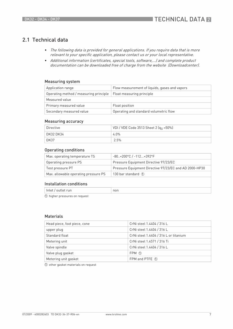
2.1 Technical data
Materials
• The following data is provided for general applications. If you require data that is more relevant to your specific application, please contact us or your local representative.
• Additional information (certificates, special tools, software,...) and complete product documentation can be downloaded free of charge from the website (Downloadcenter).
Measuring systemApplication range Flow measurement of liquids, gases and vapors
Operating method / measuring principle Float measuring principle
Measured value
Primary measured value Float position
Secondary measured value Operating and standard volumetric flow
Measuring accuracyDirective VDI / VDE Code 3513 Sheet 2 (qG =50%)
DK32 DK34 4.0%
DK37 2.5%
Operating conditionsMax. operating temperature TS -80..+200°C / -112...+392°F
Operating pressure PS Pressure Equipment Directive 97/23/EC
Test pressure PT Pressure Equipment Directive 97/23/EC and AD 2000-HP30
Max. allowable operating pressure PS 130 bar standard 1
Installation conditionsInlet / outlet run non
1 higher pressures on request
Head piece, foot piece, cone CrNi steel 1.4404 / 316 L
upper plug CrNi steel 1.4404 / 316 L
Standard float CrNi steel 1.4404 / 316 L or titanium
Metering unit CrNi steel 1.4571 / 316 Ti
Valve spindle CrNi steel 1.4404 / 316 L
Valve plug gasket FPM 1
Metering unit gasket FPM and PTFE 1
1 other gasket materials on request
TD_DK32_34_37_R04_en_PRT.book Page 7 Monday, July 27, 2009 10:05 AM
2 TECHNICAL DATA
8
DK32 - DK34 - DK37
www.krohne.com 07/2009 - 4000282603 TD DK32-34-37-R04-en
Temperatures
Indicators of DK32 DK34 DK37/M8M with limit switches
Indicator DK37/M8E
Max. process temperature at Tamb. < 40°C / 104°F
[°C] [°F]
DK32 with valve -40...+150 1 -40...+302 1
DK34 without valve -80...+150 1 -112...+302 1
DK32 DK34 with limit switches -25/-40...+145 -13/-40...+293
DK37M8M without valve -80...+150 1 -112...+302 1
DK37M8M with valve -40...+150 1 -40...+302 1
DK37/M8M with limit switches -25/-40...+150 13/-40...+302
DK37M8E with electronical indicator -25...+135 -13...+275
Max. ambient temperature Tamb. -25...+70 -13...+158
1 High temperature version up to 200°C / 392°F
Cable fitting DK3x/Kx/S M16 x 1,5
Cable diameter DKx/Kx/L 7 ... 8 mm
Clamp connection DK3x/Kx/S 1.5mm2
Limit switch SC2-N0I7S2002-N
SJ2-SN 1 SJ2-S1N 1
Type 2-wire NAMUR 2-wire NAMUR 2-wire NAMUR
Switch element function Normally closed Normally closed Normally open
Nominal voltage U0 8 VDC 8 VDC 8 VDC
Pointer shaft not read ≥3 mA ≥3 mA ≤1 mA
Pointer shaft read ≤1 mA ≤1 mA ≥3 mA
DK32 DK34 with reed contact Switching type bistable
Switching reproducibility < 5% of full scale value
Breaking capacity 12 VA 2
Max. supply voltage 30 VDC 2
Max. current 0,5 A 2
1 safety oriented2 reduced values for Ex version
Cable fitting M16 x 1.5
Cable diameter 8…10 mm
Clamp connection M8M/K - 1,5 mm2 M8E - 2,5 mm2
Measurement signal 4...20 mA for 0…100% flow value, two-wire technology
Power supply 14.8...30 VDC
Min. power supply for HART TM 20.5 VDC
Effect of supply power < 0.1%
TD_DK32_34_37_R04_en_PRT.book Page 8 Monday, July 27, 2009 10:05 AM
TECHNICAL DATA 2
9
DK32 - DK34 - DK37
www.krohne.com07/2009 - 4000282603 TD DK32-34-37-R04-en
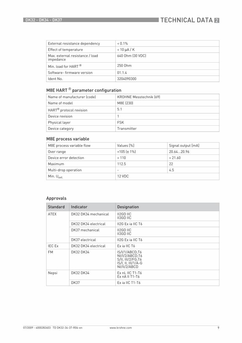
Approvals
External resistance dependency < 0.1%
Effect of temperature < 10 µA / K
Max. external resistance / load impedance
640 Ohm (30 VDC)
Min. load for HART ® 250 Ohm
Software- firmware version 01.1.4
Ident No. 3204090300
M8E HART ® parameter configurationName of manufacturer (code) KROHNE Messtechnik (69)
Name of model M8E (230)
HART® protocol revision 5.1
Device revision 1
Physical layer FSK
Device category Transmitter
M8E process variableM8E process variable flow Values [%] Signal output [mA]
Over range +105 (± 1%) 20.64...20.96
Device error detection > 110 > 21.60
Maximum 112.5 22
Multi-drop operation - 4.5
Min. Uext. 12 VDC
Standard Indicator Designation
ATEX DK32 DK34 mechanical II2GD IICII3GD IIC
DK32 DK34 electrical II2G Ex ia IIC T6
DK37 mechanical II2GD IICII3GD IIC
DK37 electrical II2G Ex ia IIC T6
IEC Ex DK32 DK34 electrical Ex ia IIC T6
FM DK32 DK34 IS/I/1/ABCD;T6NI/I/2/ABCD;T6S/II, III/2/FG;T6IS/I, II, III/1/A-GNI/II/2/ABCD
Nepsi DK32 DK34 Ex nL IIC T1-T6Ex nA II T1-T6
DK37 Ex ia IIC T1-T6
TD_DK32_34_37_R04_en_PRT.book Page 9 Monday, July 27, 2009 10:05 AM
2 TECHNICAL DATA
10
DK32 - DK34 - DK37
www.krohne.com 07/2009 - 4000282603 TD DK32-34-37-R04-en
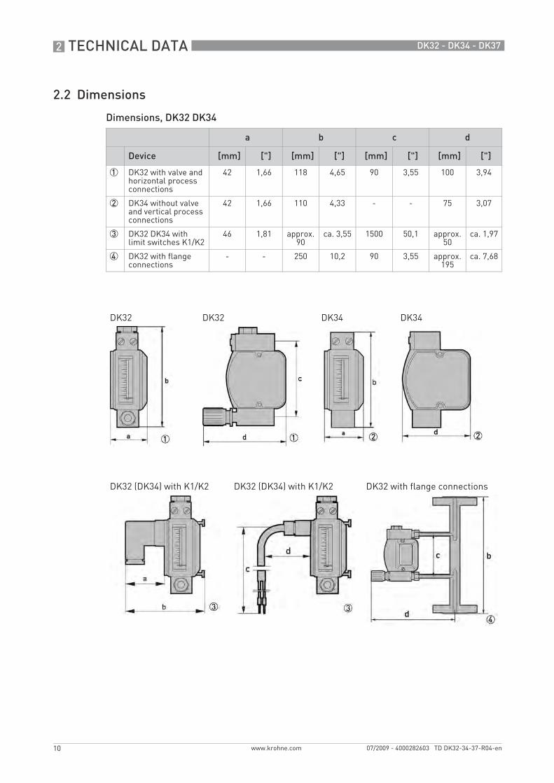
2.2 Dimensions
Dimensions, DK32 DK34
a b c d
Device [mm] ["] [mm] ["] [mm] ["] [mm] ["]
1 DK32 with valve and horizontal process connections
42 1,66 118 4,65 90 3,55 100 3,94
2 DK34 without valve and vertical process connections
42 1,66 110 4,33 - - 75 3,07
3 DK32 DK34 with limit switches K1/K2
46 1,81 approx. 90
ca. 3,55 1500 50,1 approx. 50
ca. 1,97
4 DK32 with flange connections
- - 250 10,2 90 3,55 approx. 195
ca. 7,68
DK32 DK32 DK34 DK34
DK32 (DK34) with K1/K2 DK32 (DK34) with K1/K2 DK32 with flange connections
TD_DK32_34_37_R04_en_PRT.book Page 10 Monday, July 27, 2009 10:05 AM
TECHNICAL DATA 2
11
DK32 - DK34 - DK37
www.krohne.com07/2009 - 4000282603 TD DK32-34-37-R04-en
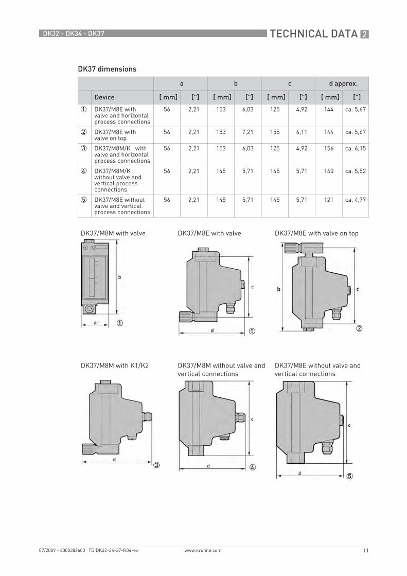
DK37 dimensions
a b c d approx.
Device [ mm] ["] [ mm] ["] [ mm] ["] [ mm] ["]
1 DK37/M8E with valve and horizontal process connections
56 2,21 153 6,03 125 4,92 144 ca. 5,67
2 DK37/M8E with valve on top
56 2,21 183 7,21 155 6,11 144 ca. 5,67
3 DK37/M8M/K . with valve and horizontal process connections
56 2,21 153 6,03 125 4,92 156 ca. 6,15
4 DK37/M8M/K . without valve and vertical process connections
56 2,21 145 5,71 145 5,71 140 ca. 5,52
5 DK37/M8E without valve and vertical process connections
56 2,21 145 5,71 145 5,71 121 ca. 4,77
DK37/M8M with valve DK37/M8E with valve DK37/M8E with valve on top
DK37/M8M with K1/K2 DK37/M8M without valve and vertical connections
DK37/M8E without valve and vertical connections
TD_DK32_34_37_R04_en_PRT.book Page 11 Monday, July 27, 2009 10:05 AM
2 TECHNICAL DATA
12
DK32 - DK34 - DK37
www.krohne.com 07/2009 - 4000282603 TD DK32-34-37-R04-en
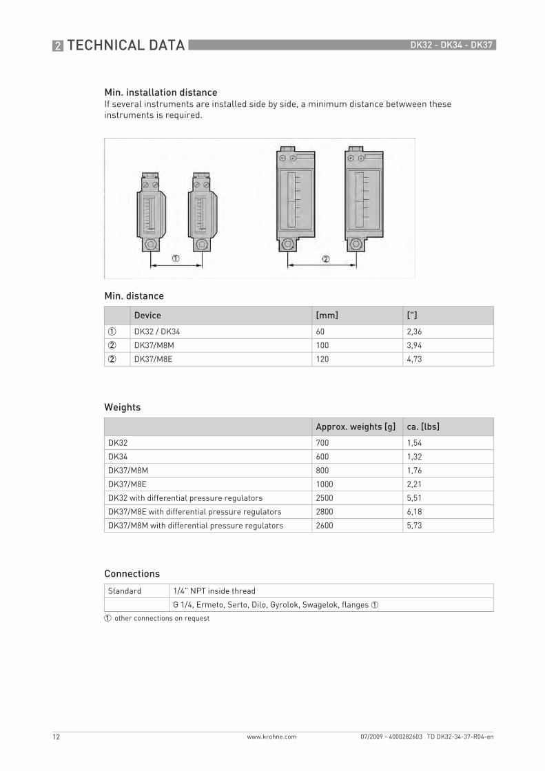
Min. installation distanceIf several instruments are installed side by side, a minimum distance betwween these instruments is required.
Min. distance
Weights
Connections
Device [mm] ["]
1 DK32 / DK34 60 2,36
2 DK37/M8M 100 3,94
2 DK37/M8E 120 4,73
Approx. weights [g] ca. [lbs]
DK32 700 1,54
DK34 600 1,32
DK37/M8M 800 1,76
DK37/M8E 1000 2,21
DK32 with differential pressure regulators 2500 5,51
DK37/M8E with differential pressure regulators 2800 6,18
DK37/M8M with differential pressure regulators 2600 5,73
Standard 1/4" NPT inside thread
G 1/4, Ermeto, Serto, Dilo, Gyrolok, Swagelok, flanges 1
1 other connections on request
TD_DK32_34_37_R04_en_PRT.book Page 12 Monday, July 27, 2009 10:05 AM
TECHNICAL DATA 2
13
DK32 - DK34 - DK37
www.krohne.com07/2009 - 4000282603 TD DK32-34-37-R04-en
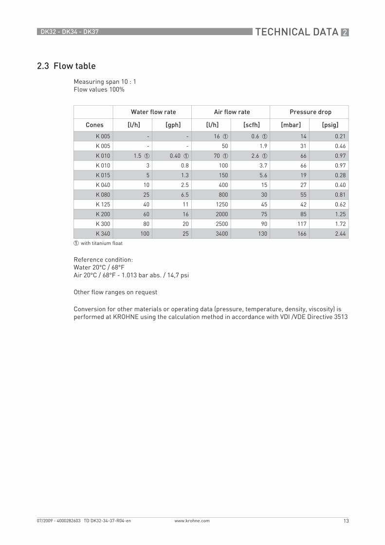
2.3 Flow table
Measuring span 10 : 1Flow values 100%
Reference condition:Water 20°C / 68°FAir 20°C / 68°F - 1.013 bar abs. / 14,7 psi
Other flow ranges on request
Conversion for other materials or operating data (pressure, temperature, density, viscosity) is performed at KROHNE using the calculation method in accordance with VDI /VDE Directive 3513
Water flow rate Air flow rate Pressure drop
Cones [l/h] [gph] [l/h] [scfh] [mbar] [psig]
K 005 - - 16 1 0.6 1 14 0.21
K 005 - - 50 1.9 31 0.46
K 010 1.5 1 0.40 1 70 1 2.6 1 66 0.97
K 010 3 0.8 100 3.7 66 0.97
K 015 5 1.3 150 5.6 19 0.28
K 040 10 2.5 400 15 27 0.40
K 080 25 6.5 800 30 55 0.81
K 125 40 11 1250 45 42 0.62
K 200 60 16 2000 75 85 1.25
K 300 80 20 2500 90 117 1.72
K 340 100 25 3400 130 166 2.44
1 with titanium float
TD_DK32_34_37_R04_en_PRT.book Page 13 Monday, July 27, 2009 10:05 AM

2 TECHNICAL DATA
14
DK32 - DK34 - DK37
www.krohne.com 07/2009 - 4000282603 TD DK32-34-37-R04-en
Valves (only DK32 and DK37)
Valve characteristics
Max. low rate Qv Valve characteristic
Valve spindle Water Air Kv Cv
Cones Ø [mm] Ø ["] [l/h] [gph] [l/h] [scfh] [m3/h] [gpm]
K 005 - K 010 1 0,039 5 1,32 100 3,72 0.018 0,021
K 015 - K 040 - K 080 2.5 0,98 50 13,2 1000 37,2 0.15 0,175
K 125 ... K 340 4.5 0,177 160 42,3 4300 160 0.48 0,552
Spindle 1,0mm - 0,039" Spindle 2,5mm - 0,098"
Spindle 4,5mm - 0,177"
1 Flow, air2 Flow, water3 Spindle rotation n
TD_DK32_34_37_R04_en_PRT.book Page 14 Monday, July 27, 2009 10:05 AM
TECHNICAL DATA 2
15
DK32 - DK34 - DK37
www.krohne.com07/2009 - 4000282603 TD DK32-34-37-R04-en
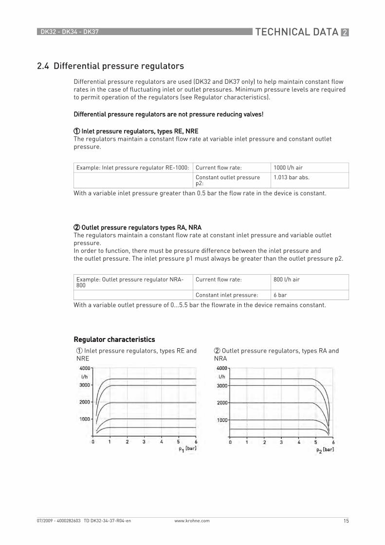
2.4 Differential pressure regulators
Differential pressure regulators are used (DK32 and DK37 only) to help maintain constant flow rates in the case of fluctuating inlet or outlet pressures. Minimum pressure levels are required to permit operation of the regulators (see Regulator characteristics).
Differential pressure regulators are not pressure reducing valves!Differential pressure regulators are not pressure reducing valves!Differential pressure regulators are not pressure reducing valves!Differential pressure regulators are not pressure reducing valves!
1111 Inlet pressure regulators, types RE, NRE Inlet pressure regulators, types RE, NRE Inlet pressure regulators, types RE, NRE Inlet pressure regulators, types RE, NREThe regulators maintain a constant flow rate at variable inlet pressure and constant outlet pressure.
2222 Outlet pressure regulators types RA, NRA Outlet pressure regulators types RA, NRA Outlet pressure regulators types RA, NRA Outlet pressure regulators types RA, NRAThe regulators maintain a constant flow rate at constant inlet pressure and variable outlet pressure.In order to function, there must be pressure difference between the inlet pressure andthe outlet pressure. The inlet pressure p1 must always be greater than the outlet pressure p2.
Regulator characteristicsRegulator characteristicsRegulator characteristicsRegulator characteristics
Example: Inlet pressure regulator RE-1000: Current flow rate: 1000 l/h air
Constant outlet pressure p2:
1.013 bar abs.
With a variable inlet pressure greater than 0.5 bar the flow rate in the device is constant.
Example: Outlet pressure regulator NRA-800
Current flow rate: 800 l/h air
Constant inlet pressure: 6 bar
With a variable outlet pressure of 0...5.5 bar the flowrate in the device remains constant.
1 Inlet pressure regulators, types RE and NRE
2 Outlet pressure regulators, types RA and NRA
TD_DK32_34_37_R04_en_PRT.book Page 15 Monday, July 27, 2009 10:05 AM
2 TECHNICAL DATA
16
DK32 - DK34 - DK37
www.krohne.com 07/2009 - 4000282603 TD DK32-34-37-R04-en
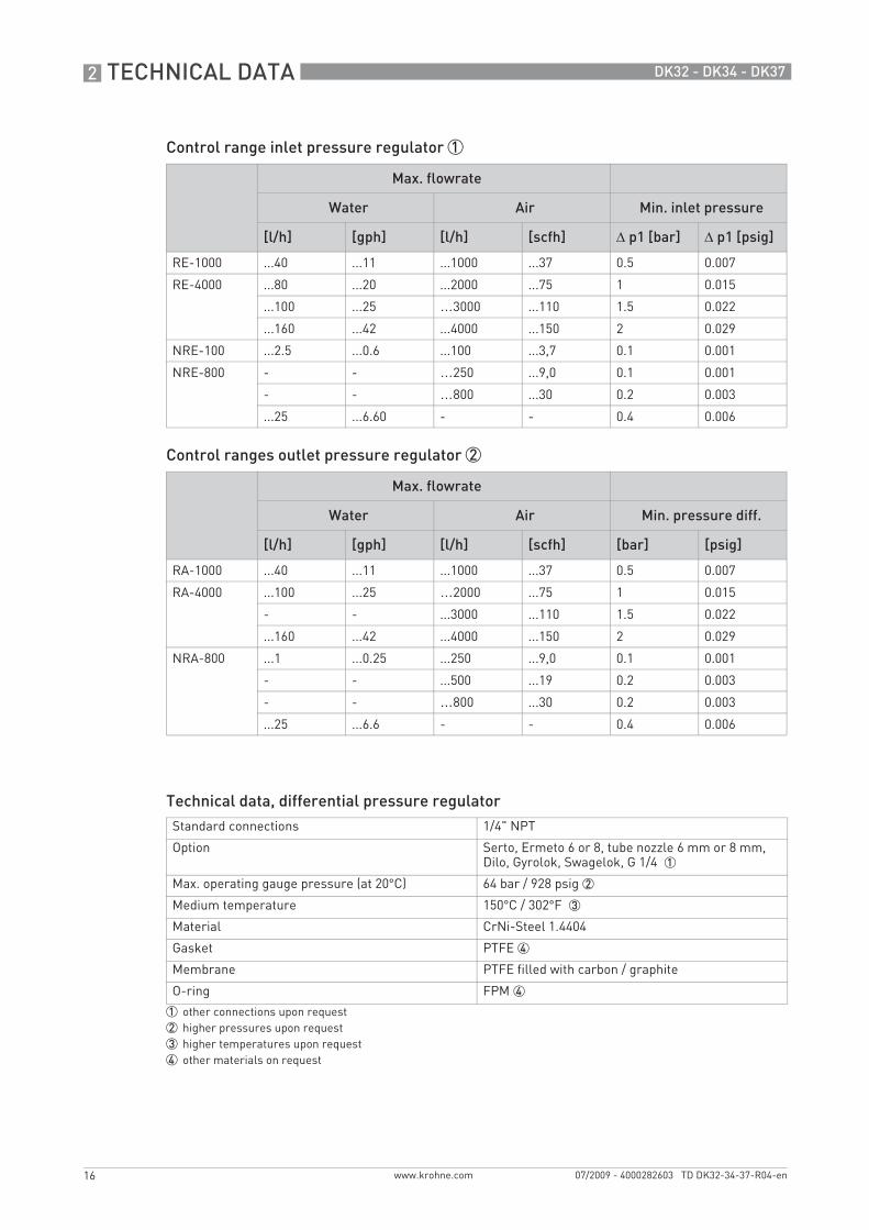
Control range inlet pressure regulator 1
Control ranges outlet pressure regulator 2
Technical data, differential pressure regulator
Max. flowrate
Water Air Min. inlet pressure
[l/h] [gph] [l/h] [scfh] Δ p1 [bar] Δ p1 [psig]
RE-1000 ...40 ...11 ...1000 ...37 0.5 0.007
RE-4000 ...80 ...20 ...2000 ...75 1 0.015
...100 ...25 …3000 ...110 1.5 0.022
...160 ...42 ...4000 ...150 2 0.029
NRE-100 ...2.5 ...0.6 ...100 ...3,7 0.1 0.001
NRE-800 - - …250 ...9,0 0.1 0.001
- - …800 ...30 0.2 0.003
...25 ...6.60 - - 0.4 0.006
Max. flowrate
Water Air Min. pressure diff.
[l/h] [gph] [l/h] [scfh] [bar] [psig]
RA-1000 ...40 ...11 ...1000 ...37 0.5 0.007
RA-4000 ...100 ...25 …2000 ...75 1 0.015
- - ...3000 ...110 1.5 0.022
...160 ...42 ...4000 ...150 2 0.029
NRA-800 ...1 ...0.25 ...250 ...9,0 0.1 0.001
- - ...500 ...19 0.2 0.003
- - …800 ...30 0.2 0.003
...25 ...6.6 - - 0.4 0.006
Standard connections 1/4" NPT
Option Serto, Ermeto 6 or 8, tube nozzle 6 mm or 8 mm, Dilo, Gyrolok, Swagelok, G 1/4 1
Max. operating gauge pressure (at 20°C) 64 bar / 928 psig 2
Medium temperature 150°C / 302°F 3
Material CrNi-Steel 1.4404
Gasket PTFE 4
Membrane PTFE filled with carbon / graphite
O-ring FPM 4
1 other connections upon request2 higher pressures upon request3 higher temperatures upon request4 other materials on request
TD_DK32_34_37_R04_en_PRT.book Page 16 Monday, July 27, 2009 10:05 AM
TECHNICAL DATA 2
17
DK32 - DK34 - DK37
www.krohne.com07/2009 - 4000282603 TD DK32-34-37-R04-en
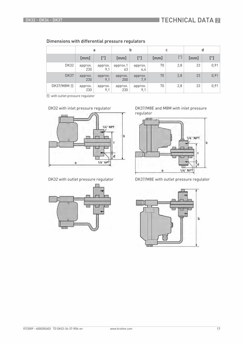
Dimensions with differential pressure regulators
a b c d
[mm] ["] [mm] ["] [mm] ["] [mm] ["]
DK32 approx.230
approx.9,1
approx.163
approx.6,4
70 2,8 23 0,91
DK37 approx.230
approx.9,1
approx.200
approx.7,9
70 2,8 23 0,91
DK37/M8M 1 approx.230
approx.9,1
approx.230
approx.9,1
70 2,8 23 0,91
1 with outlet pressure regulator
DK32 with inlet pressure regulator DK37/M8E and M8M with inlet pressure regulator
DK32 with outlet pressure regulator DK37/M8E with outlet pressure regulator
TD_DK32_34_37_R04_en_PRT.book Page 17 Monday, July 27, 2009 10:05 AM
3 INSTALLATION
18
DK32 - DK34 - DK37
www.krohne.com 07/2009 - 4000282603 TD DK32-34-37-R04-en
Installation
3.1 Intended use
The variable area flowmeters manufactured by KROHNE Messtechnik GmbH & Co. KG are suitable for measuring gases, vapors and liquids.
These flowmeters are particularly suitable for measuring:• Liquids• Hydrocarbons• Water• Chemicals with low corrosiveness• Saturated steam• Superheated steam• Industrial gases
3.2 Installation requirements
In case of instruments which are used in explosive endangered areas please consider the supplementary installation and operating instructions mentioned in the Ex-manual.
The operator shall bear sole responsibility for the use of the flowmeters with regard to suitability, intended use and corrosion resistance of the materials used to the process product.The manufacturer shall not be liable for any damage resulting from improper use or use for other than the intended purpose.Do not use any abrasive or highly viscous process products.
When installing the flowmeter in the piping please observe the following points:• The variable area flowmeter must be installed vertically (measuring principle). The flow
direction must be from bottom to top. For installation recommendations please refer also to VDI/VDE Directive 3513 Sheet 3.
• Before connecting, blow or flush out the pipes leading to the flowmeter.• Pipes for gas flow need to be dried before the flowmeter is installed.• Use connectors suitable for the particular version of the flowmeter.• Align the pipes axially with the connections on the flowmeter so that they are free of stresses.• If necessary, the piping has to be supported to prevent vibrations being transmitted to the
flowmeter.• Do not lay signal cables directly next to cables for the power supply.• If several instruments are installed side by side, a minimum distance between these divices is
required (see Technical Data).
TD_DK32_34_37_R04_en_PRT.book Page 18 Monday, July 27, 2009 10:05 AM
ELECTRICAL CONNECTIONS 4
19
DK32 - DK34 - DK37
www.krohne.com07/2009 - 4000282603 TD DK32-34-37-R04-en
Electrical connections
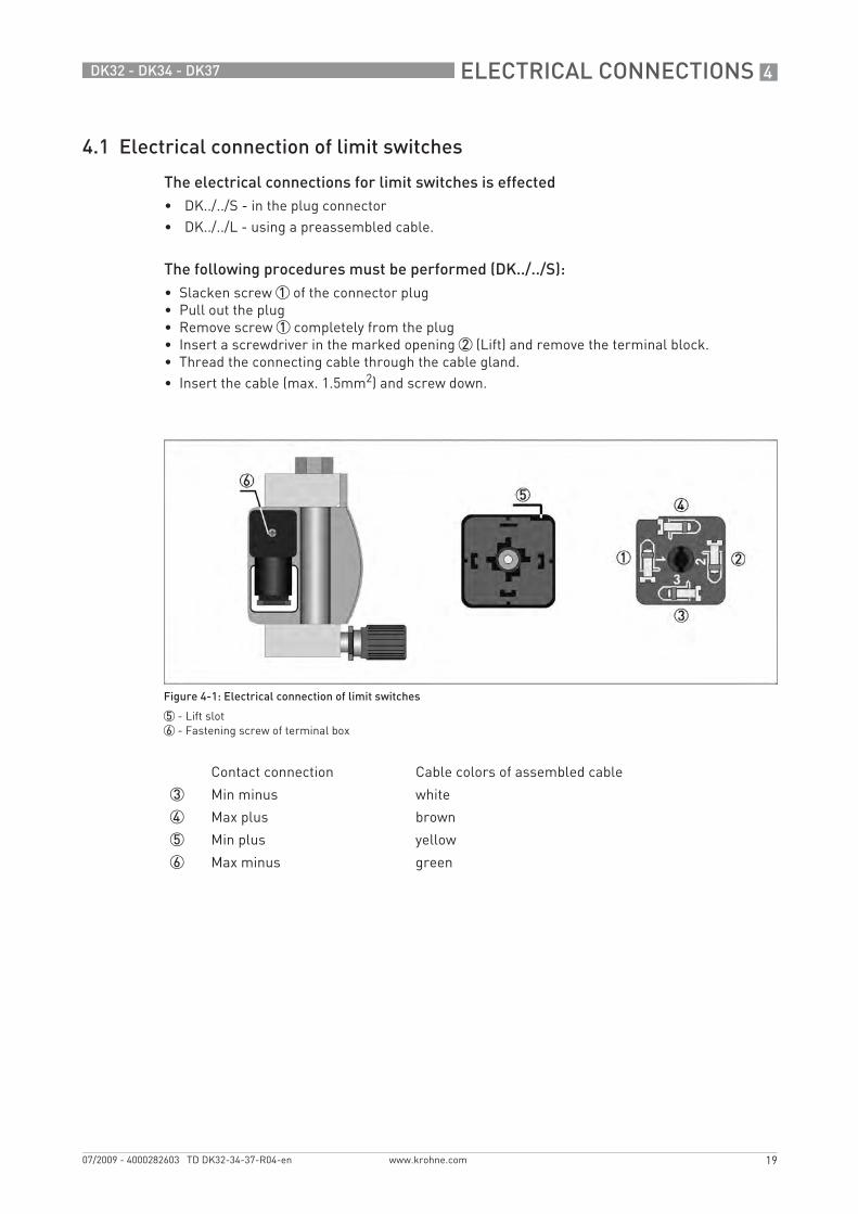
4.1 Electrical connection of limit switches
The electrical connections for limit switches is effected• DK../../S - in the plug connector• DK../../L - using a preassembled cable.
The following procedures must be performed (DK../../S):• Slacken screw 1 of the connector plug• Pull out the plug• Remove screw 1 completely from the plug• Insert a screwdriver in the marked opening 2 (Lift) and remove the terminal block.• Thread the connecting cable through the cable gland.• Insert the cable (max. 1.5mm2) and screw down.
Figure 4-1: Electrical connection of limit switches
5 - Lift slot6 - Fastening screw of terminal box
Contact connection Cable colors of assembled cable
3 Min minus white
4 Max plus brown
5 Min plus yellow
6 Max minus green
TD_DK32_34_37_R04_en_PRT.book Page 19 Monday, July 27, 2009 10:05 AM

4 ELECTRICAL CONNECTIONS
20
DK32 - DK34 - DK37
www.krohne.com 07/2009 - 4000282603 TD DK32-34-37-R04-en
Connection three-wire reed contactConnection three-wire reed contactConnection three-wire reed contactConnection three-wire reed contact
4.2 DK37/M8M limit switches
The limit switches can be set over the entire measuring range using the maximum pointer. The set limit values are displayed on the scale. The pointers are set to the desired limit values using a slip coupling along the scale.
Figure 4-2: Electrical connection of reed contact limit switch
Strand colours for flowmeters with preassembled cables:
1 Silicone-insulated wire - yellow/green / FEP-insulated wire - red 2 Silicone-insulated wire - brown / FEP-insulated wire - brown3 Silicone-insulated wire - blue / FEP-insulated wire - blue
Figure 4-3: Limit switch setting
1 Maximum pointer, switching point indicator2 Limit switch3 Connection board4 Connection terminal
TD_DK32_34_37_R04_en_PRT.book Page 20 Monday, July 27, 2009 10:05 AM
ELECTRICAL CONNECTIONS 4
21
DK32 - DK34 - DK37
www.krohne.com07/2009 - 4000282603 TD DK32-34-37-R04-en
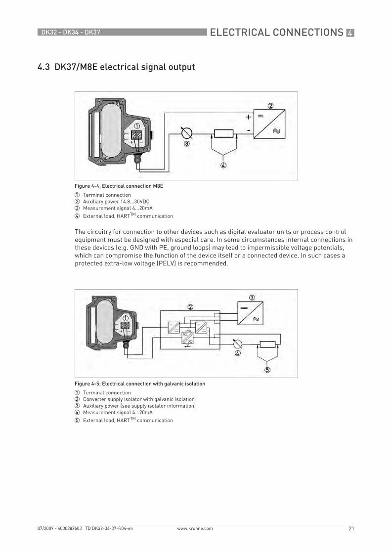
4.3 DK37/M8E electrical signal output
The circuitry for connection to other devices such as digital evaluator units or process control equipment must be designed with especial care. In some circumstances internal connections in these devices (e.g. GND with PE, ground loops) may lead to impermissible voltage potentials, which can compromise the function of the device itself or a connected device. In such cases a protected extra-low voltage (PELV) is recommended.
Figure 4-4: Electrical connection M8E
1 Terminal connection2 Auxiliary power 14.8...30VDC3 Measurement signal 4...20mA
4 External load, HARTTM communication
Figure 4-5: Electrical connection with galvanic isolation
1 Terminal connection2 Converter supply isolator with galvanic isolation3 Auxiliary power (see supply isolator information)4 Measurement signal 4...20mA
5 External load, HARTTM communication
TD_DK32_34_37_R04_en_PRT.book Page 21 Monday, July 27, 2009 10:05 AM
4 ELECTRICAL CONNECTIONS
22
DK32 - DK34 - DK37
www.krohne.com 07/2009 - 4000282603 TD DK32-34-37-R04-en
4.3.1 Power supply
The required supply voltage can be calculated using the formula below:
Uext. = RL.22 mA + 14.8 V
whereUext. = the minimum supply voltage andRL = the total measuring loop resistance.
4.3.2 Load for HART® communication
The maximum load impedance is calculated as follows:
4.3.3 Parametrization
The M8E electronic display can be parametrized via HART® communications. DD (Device Descriptions) for AMS 6.x and PDM 5.2 and a DTM (Device Type Manager) are available for parametrization (download center at www.krohne.comwww.krohne.comwww.krohne.comwww.krohne.com).The current flowrate can be transmitted using the integral HART® communications. A flow counter can be parametrized. Two limit values can be monitored. The limit values are assigned either to flow values or to the counter overflow. The limit values are not depicted on the display.
The supply voltage has to be between 14.8 VDC and 30 VDC. This is based on the total resistance of the measuring loop. To determine this, add up the resistances of each component in the measuring loop (not including the meter).
The power supply has to be able to supply a minimum of 22 mA.
For HART® communication a load of at least 230 ohm is required.
Use a twisted two-core cable to prevent electrical interference from impeding the DC output signal. In some cases a shielded cable may be necessary. The cable shield may only be earthed (grounded) at one place (on the power supply unit).
TD_DK32_34_37_R04_en_PRT.book Page 22 Monday, July 27, 2009 10:05 AM
ORDER FORM 5
23
DK32 - DK34 - DK37
www.krohne.com07/2009 - 4000282603 TD DK32-34-37-R04-en
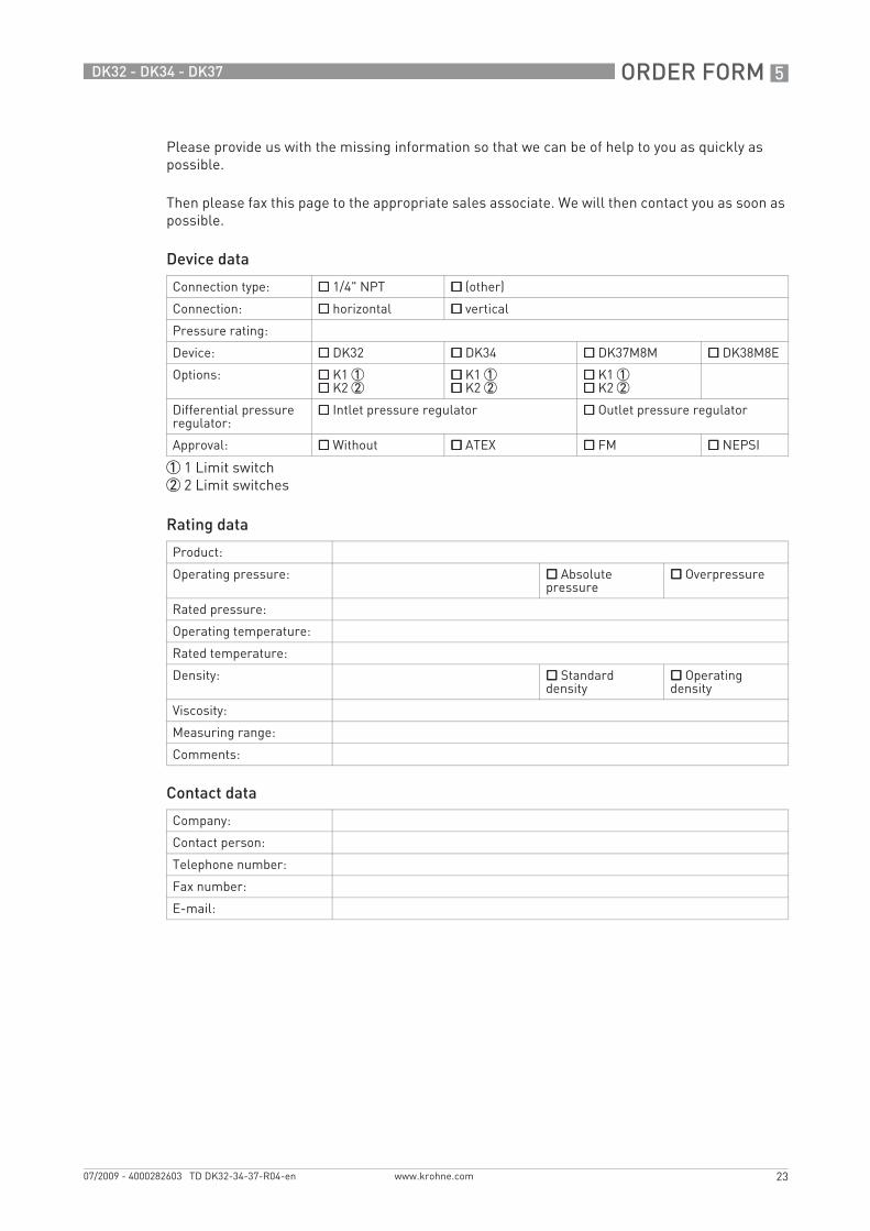
Order form
Please provide us with the missing information so that we can be of help to you as quickly as possible.
Then please fax this page to the appropriate sales associate. We will then contact you as soon as possible.
Device data
Rating data
Contact data
Connection type: 1/4" NPT (other)
Connection: horizontal vertical
Pressure rating:
Device: DK32 DK34 DK37M8M DK38M8E
Options: K1 1 K2 2
K1 1 K2 2
K1 1 K2 2
Differential pressure regulator:
Intlet pressure regulator Outlet pressure regulator
Approval: Without ATEX FM NEPSI
1 1 Limit switch2 2 Limit switches
Product:
Operating pressure: Absolute pressure
Overpressure
Rated pressure:
Operating temperature:
Rated temperature:
Density: Standard density
Operating density
Viscosity:
Measuring range:
Comments:
Company:
Contact person:
Telephone number:
Fax number:
E-mail:
TD_DK32_34_37_R04_en_PRT.book Page 23 Monday, July 27, 2009 10:05 AM

KROHNE product overview
• Electromagnetic flowmeters
• Variable area flowmeters
• Ultrasonic flowmeters
• Mass flowmeters
• Vortex flowmeters
• Flow controllers
• Level meters
• Temperature meters
• Pressure meters
• Analysis products
• Measuring systems for the oil and gas industry
• Measuring systems for sea-going tankers
Head Office KROHNE Messtechnik GmbH & Co. KG Ludwig-Krohne-Str. 5D-47058 Duisburg (Germany)Tel.:+49 (0)203 301 0Fax:+49 (0)203 301 10389 [email protected]
© K
RO
HN
E 07
/200
9 -
4000
2826
03
TD D
K32
-34-
37-R
04-e
n -
Subj
ect t
o ch
ange
with
out n
otic
e.
The current list of all KROHNE contacts and addresses can be found at:www.krohne.com
KK
K
TD_DK32_34_37_R04_en_PRT.book Page 24 Monday, July 27, 2009 10:05 AM