DIVISION 33 - UTILITIES Section Title Number · PDF fileDIVISION 33 - UTILITIES Section Title...
51
DIVISION 33 - UTILITIES Section Title Number Technical Standards Revised 12/15/2012 1 of 51 33 00 00 UTILITIES 33 10 00 WATER UTILITIES 33 11 00 Water Utility Distribution Piping 33 11 16 Site Water Utility Distribution Piping 33 11 50 Reclaimed Water Distribution System 33 30 00 SANITARY SEWERAGE UTILITIES 33 31 13 Public Sanitary Utility Sewerage Piping 33 40 00 STORM DRAINAGE UTILITIES 33 41 13 Public Storm Utility Drainage Piping 33 50 00 FUEL DISTRIBUTION UTILITIES 33 51 13 Natural Gas Piping 33 60 00 HYDRONIC AND STEAM ENERGY UTILITIES 33 61 13 Chilled Water Distribution System 33 63 20 Steam and High Temperature Hot Water Tunnels 33 70 00 ELECTRICAL UTILITIES 33 71 00 Electrical Utility Transmission and Distribution 33 71 39 High Voltage Wiring (Above 600-Volt) 33 71 73 Electrical Utility Services 33 73 00 Utility Transformers 33 80 00 COMMUNICATION UTILITIES 33 81 00 Communication Structures 33 81 26 Communications Underground Ducts, Manholes, and Handholes 33 82 00 Communications Distribution 33 82 01 Switching Center Terminations 33 82 13 Copper Communications Distribution Cabling 33 82 23 Optical Fiber Communications Distribution Cabling
Transcript of DIVISION 33 - UTILITIES Section Title Number · PDF fileDIVISION 33 - UTILITIES Section Title...

DIVISION 33 - UTILITIES Section Title Number
Technical Standards Revised 12/15/2012
1 of 51
33 00 00 UTILITIES 33 10 00 WATER UTILITIES 33 11 00 Water Utility Distribution Piping 33 11 16 Site Water Utility Distribution Piping 33 11 50 Reclaimed Water Distribution System 33 30 00 SANITARY SEWERAGE UTILITIES 33 31 13 Public Sanitary Utility Sewerage Piping 33 40 00 STORM DRAINAGE UTILITIES 33 41 13 Public Storm Utility Drainage Piping 33 50 00 FUEL DISTRIBUTION UTILITIES 33 51 13 Natural Gas Piping 33 60 00 HYDRONIC AND STEAM ENERGY UTILITIES 33 61 13 Chilled Water Distribution System 33 63 20 Steam and High Temperature Hot Water Tunnels 33 70 00 ELECTRICAL UTILITIES 33 71 00 Electrical Utility Transmission and Distribution 33 71 39 High Voltage Wiring (Above 600-Volt) 33 71 73 Electrical Utility Services 33 73 00 Utility Transformers 33 80 00 COMMUNICATION UTILITIES 33 81 00 Communication Structures 33 81 26 Communications Underground Ducts, Manholes, and Handholes 33 82 00 Communications Distribution 33 82 01 Switching Center Terminations 33 82 13 Copper Communications Distribution Cabling 33 82 23 Optical Fiber Communications Distribution Cabling

DIVISION 33 - UTILITITES Section Title Number
Technical Standards Revised 12/15/2012
2 of 51
33 00 00 UTILITIES 33 11 00 Water Utility Distribution Piping 33 11 16 Site Water Utility Distribution Piping
Part 1 - General This section defines the general design parameters for the water distribution system, including domestic and fire protection water distribution, service lines, fire hydrants and system appurtenances. The Design Professional (DP) shall conduct a Fire Flow test at the project site. Tests shall be performed by the University and witnessed by the Fire Marshal, NAU Risk Management. The Design Professional (DP) shall size the piping system based on the design flows. Coordinate with the Project Manager regarding existing flows and pressures within the system and provisions for future campus expansion and additional demands in the system. Submit calculations to the Project Manager. Valves, install valves on three sides of all tees and four sides of all crosses. Maximum spacing between valves shall not exceed 300 feet. Refer to Division 23 for meter requirements and connections to the EMCS system. Design and construction of all water systems shall comply with the rules and regulations of the Arizona Department of Environmental Quality (ADEQ) and the Arizona Administrative Code (ACC). Part 2 – Products All materials that will come in contact with potable water shall conform to ANSI/NSF Standard 61 and the rules and regulations of the Arizona Department of Environmental Quality. All material used in the construction of Fire Service lines shall conform to NFPA 13 and NFPA 24. All material shall conform to the requirements of Underwriter’s Laboratory (UL) or Factory Mutual (FM), and listed. Polyvinyl Chloride (PVC) Pipe 4-inch diameter to 12” diameter shall conform to AWWA C900, Class 200 (SDR 14) and cast iron outside diameter. Elastomeric gaskets shall conform to ASTM F477 providing a water tight seal when tested in accordance with ASTM D3139. Fittings used on PVC pipe shall be mechanical joint ductile iron (DI) fittings as specified below.

DIVISION 33 - UTILITITES Section Title Number
Technical Standards Revised 12/15/2012
3 of 51
Ductile Iron Pipe Ductile Iron Pipe (DIP): All pipes shall be push-on Tyton joint, mechanical joint (MJ) joint or integral restrained joint ductile iron pipe. The pipe shall be manufactured and tested in accordance with the American Water Works Association (AWWA) Standard C151, and have working pressure (pressure class) of not less than:
4”-12” dia (Class 350) 350 PSI
Rubber gasket joints shall satisfy requirements of AWWA C111. Flanged ductile iron pipe shall be manufactured in accordance with AWWA C115, Flange Class 250. The minimum thickness class for ductile iron pipe to be threaded shall be thickness Class 53. Threads for threaded flanged pipe shall be taper pipe threads in accordance with ANSI B2.1, with thread diameters adjusted to conform to ductile iron pipe standard outside diameters. All ductile iron pipe shall have a standard thickness cement-mortar lining followed by a seal coat of asphaltic material in accordance with AWWA C104. The exterior surfaces of all ductile iron pipe and fittings shall be coated with a bituminous material in accordance with AWWA C151 before shipment. Ductile Iron Fittings and specials shall conform to AWWA C110, AWWA C153, and AWWA C111. Fittings and specials shall be cement-mortar lined in accordance with AWWA C104. Linings shall be standard thickness and seal coated with a bituminous material. The exterior surfaces of all ductile iron fittings shall be coated with a bituminous material in accordance with AWWA C110.
Control Valves Gate valves (4” to 12”) shall be resilient seated gate valves meeting the requirements of AWWA C509, and Maricopa Association of Governments Uniform Standard Specifications and Details for Public Works Construction Standard Specification No. 630. The valves shall be rated bubble tight at 200 PSI. The exterior and interior shall be coated with a thermo-setting or fusion bonded epoxy coating meeting the requirements of AWWA C550. The dry coating thickness shall not be less than 12 mils. Valves shall have mechanical style connections, except flanged joints may be used on the side of the valve that connects directly to a tee or tapping sleeve. Direct buried valves shall have a 2-inch operating nut.
The direction to open the valve shall be to the left (counter clockwise). Valves shall have a minimum of two (2) turns per inch of diameter.

DIVISION 33 - UTILITITES Section Title Number
Technical Standards Revised 12/15/2012
4 of 51
Valves shall be rate for a minimum working pressure 250 PSI and be tested and certified by the manufacturer as being bubble tight at 200 PSI. Fire Hydrants shall comply with the City of Flagstaff (COF) Engineering Design Standard 9-06-060. Fire Hydrants shall be manufactured and tested in accordance with AWWA C502, dry barrel fire hydrants. Hydrants shall be traffic type with break-a-way flange unit installed just above grade. Tapping Sleeves shall conform to MAG Specification No. 630. Sleeves shall be ductile iron or fabricated from ¼-inch (minimum) ASTM 286 Grade C steel or ASTM A-36 steel. Sleeves shall be factory coated with corrosion resistant epoxy in accordance with AWWA C550. Flange shall be 150 LBS MSS-SP60. Bolts shall be corrosion resistant, high strength, low –alloy, per AWWA C-111. Gasket shall be Burna-N or neoprene. Sleeves shall be rated for 250 psi. Tapping sleeves shall be furnished with a 3/4 inch test plug. Plug shall be bronze NPT, coupling shall be epoxy coated. Backflow Assemblies shall be reduced pressure backflow assemblies conforming to AWWA C511 and approved by the Foundation for Cross-Connection Control and Hydraulic Research at the University of Southern California. Assemblies shall have OS&Y resilient seated gate valves and shall be epoxy coated per AWWA C550. Assemblies shall be installed in buildings or protected from freezing. Couplings used on ductile iron and PVC C900 pipe shall be ductile iron, solid sleeves with mechanical joints, complying with AWWA C110 and C111 and as specified for ductile iron fittings. Couplings shall be fully restrained. Air Relief Valves shall be vacuum and air relief valves shall be of the size shown on the plans. Corporations shall be full opening with O-ring seal and bronze ball and conform to AWWA C800. Taps into ductile iron pipe may be made by direct tapping of the pipe or with a service saddle. Taps into PVC pipe shall be made with a service saddle. Service saddles shall conform to AWWA C800, and be constructed of bronze or epoxy coated ductile iron. Saddles shall have a single or double strap. The outlet of the valve shall be equipped with a gooseneck and stainless steel screen as indicated on the drawings. Copper tubing shall be Type K, ASTM B88.
Joint Restraint Devices All joints, fittings, and valves within the system shall be fully restrained. Ductile iron fittings mechanical style joints - EBAA Iron Sales, Inc. “Mega Lug” joint restraint or approved equal. The specific model utilized shall be compatible with the type of pipe (DIP or PVC) connected to the fitting. PVC pipe push-on style joints – EBAA Iron Sales Series 1600, or approved equal.

DIVISION 33 - UTILITITES Section Title Number
Technical Standards Revised 12/15/2012
5 of 51
Ductile iron push-on style joints – EBAA Iron Sales Series 1700, or approved equal. Ductile iron pipe integral joint restraint type - U.S. Pipe “TR Flex” restrained joint pipe and fittings. Pacific States Thrust-Lock. Integral joint restraint type - U.S. Pipe “TR Flex” restrained joint pipe and fittings, Pacific States “Thrust Lock” joint system, Griffin Pipe “Snap Lok” joint system, or approved equal. The use of gaskets with integral restraint grippers shall not be permitted. Valve Boxes and cover shall consist of a cast iron box and cover and PVC riser. The valve box and cover casting shall be manufactured in conformance with ASTM A48, Class 30B. Cover shall be labeled “Water”, and paint box blue. Valve stem risers shall comply with Maricopa Association of Governments Uniform Standard Specifications and Details for Public Works Construction Standard Specification No. 610 and as detailed on the plans. Polyethylene Encasement (DI Pipe) shall conform to AWWA C105. The color of the polyethylene encasement shall be black or blue. Tracer Wire shall be 12 AWG solid copper, or stranded copper wire, PVC insulated, type UF, UL listed for direct burial in ground. Provide wire in 1,000 feet or 2,500 feet rolls. Splicing system shall consist of a copper wire crimp, PVC split case gland, and epoxy waterproof sealing compound.
Install locator wire to the top of the all water line. The Contractor shall minimize the number of splices in the wire. All splices shall be made with a watertight gland. Trace wire shall be required on all newly installed utilities that extend outside of the building to the point where contract boundaries end. If tying into an existing utility and that utility will not come above ground, (tying into an existing sewer line for example), then the trace wire shall be brought to the surface and terminated in a small underground j-box directly above the newly installed utility. J-box lid shall be marked “trace wire” and what utility the trace wire is for. If a utility comes above ground, (fire hydrant for example), then the trace wire shall come above ground with the same utility.
DIVISION 33 - UTILITITES Section Title Number
Technical Standards Revised 12/15/2012
6 of 51
Part 3 – Execution General Fire service lines shall be installed in accordance with NFPA 13 and NFPA 24. Minimum depth of cover, measured from top of pipe, shall be as follows; Water Mains: 36-inches Fire Service Mains: 42-inches (12-inches below frost depth). Pipe and Fittings Do not make the connections to the existing system until such time that the system has been cleaned; flushed, disinfected, and all hydrostatic testing has been completed and accepted. All work associated with modifications to the water system, fire service lines, and building service lines shall be carried an expeditious manner to minimize the time frame during which the water supply to the campus facilities and building automatic fire sprinkler system is impacted. All shutdowns shall be scheduled in advanced with the Owner, and the Owner reserves the right to require shutdowns to occur during non-standard work times to mitigate the impact on the campus functions. No water main or service line shall be taken out of service until all piping, fittings, and appurtenances, required to complete the system modifications and return the system to operating condition, are available on the project site. PVC pipe shall be installed in accordance with the requirements of AWWA C605, the manufacturer’s recommendations and Maricopa Association of Governments Uniform Standard Specifications and Details for Public Works Construction Standard Specification No. 610, and as specified herein. Ductile-Iron Pipe Install in accordance with the recommended procedures set forth in AWWA C600 and Maricopa Association of Governments Uniform Standard Specifications and Details for Public Works Construction Standard Specification No. 610, and as specified herein.
The maximum allowable joint deflection will be as given in AWWA C600, AWWA C605. If the alignment required deflection in excess of the above limitations, special bends or a sufficient number of shorter lengths of pipe shall be utilized to provide angular deflections within the limits set forth. Install all joint restraint devices in accordance with the manufacturer's instructions and prior to pressure testing of the system. Do no bend or deflect the pipe. All piping shall be fully restrained.

DIVISION 33 - UTILITITES Section Title Number
Technical Standards Revised 12/15/2012
7 of 51
Install all valves in accordance with the manufacturer's instructions. When the top of the operating nut is 4 feet or greater below finish grade, install a valve nut extension. Install air relief valves at high points. Cleaning and Flushing It shall be the responsibility of the Contractor to keep the lines clean of all foreign materials during construction. Flush lines per ADEQ Rules and regulations. The system shall be flushed at a minimum of 2.5 FPS for a minimum of 60 seconds per 100 feet of pipe. Water used for flushing shall be potable water. Should dirt, debris, and/or foreign material be allowed to accumulate in the lines, the Contractor shall be responsible to remove all such material from the line by flushing the lines or other approved methods. In the event that such measures are required, the Contractor shall provide a written proposal to the Owner stating the methods to be utilized. In review of the proposal, the Owner will consider the potential for adverse impacts on the Campus.
Disinfection Disinfect all lines per ADEQ rules and regulations. Disinfect all lines per ADEQ Engineering Bulletin No. 8. The Contractor shall submit a disinfecting plan to the Owner’s review. The plan shall detail the method for disinfecting the system and identify the certified laboratory that will sample and perform the microbiological testing. The Contractor shall be responsible for the cost of all laboratory testing.
Separation Between Potable Water Mains and Sewers/Reclaimed Water Mains Per ADEQ rules and regulations. Hydrostatic testing shall conform to AWWA C600 / C605 at a test pressure of 200 PSI, modified as follows. Allowable Leakage Determination: During the 2 hour, 200 PSI pressure test, the makeup water to maintain the test pressure within 5 psi of the test pressure and re-pressurize the system to the starting pressure shall be measured. Leakage is defined as the quantity of water to be supplied into the newly laid pipe, or approved section thereof, necessary to maintain the specified leakage test pressure after the pipe has been filled with water and the air expelled. No piping installation will be accepted until the leakage is less than the number of gallons per hour as determined by the formula:
DIVISION 33 - UTILITITES Section Title Number
Technical Standards Revised 12/15/2012
8 of 51
L = 0.00013 * N * D * (P raised to 1/2 power) In which L equals the allowable leakage in gallons per hour; N is the number of joints in the length of pipeline tested; D is the nominal diameter of the pipe in inches; and P is the average test pressure during the leakage test, in psi gauge. Should any test of pipe disclose leakage greater than that specified in the foregoing table, the defective joints shall be located and repaired until the leakage is within the specified allowance, without additional cost to the Owner. The Contractor shall provide certified test pressure gauges, calibrated within 8 months of the test. The gauges shall be a minimum of 4-inches in diameter, with a 1 psi scale. After installation of the tapping sleeve and valve and prior to making the tap, the sleeve shall be tested at 200 psi for 2 hours. There shall be no pressure drop during the test period.
System Connections Unless specifically approved by the Owner in writing, connections to the existing system shall be made only after all pipes have been disinfected and all hydrostatic testing have been approved by the Owner. Where utility access hatches/vaults/manholes are installed within 2 feet of sidewalks, they shall be 1 inch below top of finished sidewalk to accommodate snow removal without damage to boxes or lids. Where utility access hatches/vaults/manholes are installed in sidewalks, patios, roadways, or any other structure where snow removal shall occur, the top of the access hatches shall be a minimum of ¼” and a maximum of ½” below finished surface of concrete to accommodate for snow removal without damage to boxes or lids.
33 11 50 Reclaimed Water Distribution System Part 1 – General
This Section includes the following for direct buried reclaimed water distribution systems, including mains, service lines, pipe, fittings, valves, and joint Restraint. The Design Professional (DP) shall size the piping system based on the design flows. The maximum velocity in the system shall be 5 feet per second. Coordinate with the Project Manager the existing flows and pressures within the system and provisions for future campus expansions. Submit calculations to the Project Manager.

DIVISION 33 - UTILITITES Section Title Number
Technical Standards Revised 12/15/2012
9 of 51
Valves, install valves on three sides of all tees and four sides of all crosses. Maximum spacing between valves shall not exceed 300 feet. Refer to Division 23 for meter requirements and connections to the EMCS system. Part 2 – Products Polyvinyl Chloride (PVC) Pipe, PVC pipe 4-inch diameter to 12” diameter shall conform to AWWA C900, Class 200 (SDR 14) and cast iron outside diameter. Elastomeric gaskets shall conform to ASTM F477 providing a water tight seal when tested in accordance with ASTM D3139. Fittings used on PVC pipe shall be mechanical joint ductile iron (DI) fittings as specified below.
Ductile Iron Pipe Ductile Iron Pipe (DIP): All pipes shall be push-on Tyton joint, mechanical joint (MJ) joint or integral restrained joint ductile iron pipe. The pipe shall be manufactured and tested in accordance with the American Water Works Association (AWWA) Standard C151, and have working pressure (pressure class) of not less than: 4”-12” dia (Class 350) 350 PSI Rubber gasket joints shall satisfy requirements of AWWA C111. Flanged ductile iron pipe shall be manufactured in accordance with AWWA C115, Flange Class 150. The minimum thickness class for ductile iron pipe to be threaded shall be Class 53. Threads for threaded flanged pipe shall be taper pipe threads in accordance with ANSI B2.1, with thread diameters adjusted to conform to ductile iron pipe standard outside diameters All ductile iron pipe shall have a double thickness cement-mortar lining followed by a seal coat of asphaltic material in accordance with AWWA C104. The exterior surfaces of all ductile iron pipe and fittings shall be coated with a bituminous material in accordance with AWWA C151 before shipment. Ductile Iron Fittings Fittings and specials shall conform to AWWA C110, AWWA C153, and AWWA C111. Fittings and specials shall be doubled cement-mortar lined in accordance with AWWA C104 and seal coated with a bituminous material. The exterior surfaces of all ductile iron fittings shall be coated with a bituminous material in accordance with AWWA C110. Control Valves Gate valves (4” to 12”) shall be resilient seated gate valves meeting the requirements of AWWA C509, and Maricopa Association of Governments Uniform Standard Specifications and Details for Public Works Construction

DIVISION 33 - UTILITITES Section Title Number
Technical Standards Revised 12/15/2012
10 of 51
Standard Specification No. 630. The valves shall be rated bubble tight at 200 PSI. The exterior and interior shall be coated with a thermo-setting or fusion bonded epoxy coating meeting the requirements of AWWA C550. The dry coating thickness shall not be less than 12 mils. Valves shall have mechanical style connections, except flanged joints may be used on the side of the valve that connects directly to a tee or tapping sleeve. Direct buried valves shall have a 2-inch operating nut. The direction to open the valve shall be to the left (counter clockwise). Valves shall have a minimum of two (2) turns per inch of diameter.
Valves shall be rate for a minimum working pressure 250 PSI and be tested and certified by the manufacturer as being bubble tight at 200 PSI. Tapping sleeves shall conform to MAG Specification No. 630. Sleeves shall be ductile iron or fabricated from ¼-inch (minimum) ASTM 286 Grade C steel or ASTM A-36 steel. Sleeves shall be factory coated with corrosion resistant epoxy in accordance with AWWA C550. Flange shall be 150 LBS MSS-SP60. Bolts shall be corrosion resistant, high strength, low –alloy, per AWWA C-111. Gasket shall be Burna-N or neoprene. Sleeves shall be rated for 250 psi. Tapping sleeves shall be furnished with a 3/4 inch test plug. Plug shall be bronze NPT, coupling shall be epoxy coated Air Relief Valves shall be vacuum and air relief valves shall be of the size shown on the plans. Corporations shall be full opening with O-ring seal and bronze ball and conform to AWWA C800. Taps into ductile iron pipe may be made by direct tapping of the pipe or with a service saddle. Taps into PVC pipe shall be made with a service saddle. Service saddles shall conform to AWWA C800, and be constructed of bronze or epoxy coated ductile iron. Saddles shall have a single or double strap. The outlet of the valve shall be equipped with a gooseneck and stainless steel screen as indicated on the drawings. Copper tubing shall be Type K, ASTM B88. Joint Restraint Devices All joints, fittings, and valves within the system shall be fully restrained.
Ductile iron fittings mechanical style joints - EBAA Iron Sales, Inc. “Mega Lug” joint restraint or approved equal. The specific model utilized shall be compatible with the type of pipe (DIP or PVC) connected to the fitting. PVC pipe push-on style joints – EBAA Iron Sales Series 1600, or approved equal. Ductile iron push-on style joints – EBAA Iron Sales Series 1700, or approved equal.

DIVISION 33 - UTILITITES Section Title Number
Technical Standards Revised 12/15/2012
11 of 51
Ductile iron pipe integral joint restraint type - U.S. Pipe “TR Flex” restrained joint pipe and fittings. Pacific States Thrust-Lock. Integral joint restraint type - U.S. Pipe “TR Flex” restrained joint pipe and fittings, Pacific States “Thrust Lock” joint system, Griffin Pipe “Snap Lok” joint system, or approved equal. The use of gaskets with integral restraint grippers shall not be permitted. Couplings used on ductile iron and PVC C900 pipe shall be ductile iron, solid sleeves with mechanical joints, complying with AWWA C110 and C111 and as specified for ductile iron fittings. Couplings shall be fully restrained. Valve box and cover shall consist of a cast iron box and cover and PVC riser. The valve box and cover casting shall be manufactured in conformance with ASTM A48, Class 30B. Cover shall be labeled “RW” or provided with no logo, and paint box purple. Where underground valve boxes or utility access boxes are installed within 2 feet of sidewalks, they shall be 1 inch below top of finished sidewalk to accommodate for snow removal with damage to boxes or lids. Where underground valve boxes or utility access boxes are installed in sidewalks, patios, concrete steps, or any other structure where snow removal shall occur, the top of the boxes shall be a minimum of ¼” and a maximum of ½” below finished surface of concrete to accommodate for snow removal without damage of boxes or lids. Valve stem risers shall comply with Maricopa Association of Governments Uniform Standard Specifications and Details for Public Works Construction Standard Specification No. 610 and as detailed on the plans. Polyethylene Encasement (DI Pipe) shall conform to AWWA C105. The color of the polyethylene encasement shall be purple. Tracer Wire shall be 12 AWG solid copper, or stranded copper wire, PVC insulated, type UF, UL listed for direct burial in ground. Provide wire in 1,000 feet or 2,500 feet rolls. Splicing system shall consist of a copper wire crimp, PVC split case gland, and epoxy waterproof sealing compound. Part 3 – Execution Minimum depth of cover, measured from top of pipe, shall be as follows; Reclaimed water mains: 42-inches Reclaimed water service lines: 36-inches

DIVISION 33 - UTILITITES Section Title Number
Technical Standards Revised 12/15/2012
12 of 51
Pipe and Fittings PVC pipe shall be installed in accordance with the requirements of AWWA C605, the manufacturer’s recommendations and Maricopa Association of Governments Uniform Standard Specifications and Details for Public Works Construction Standard Specification No. 610, and as specified herein. Ductile-Iron Pipe: Install in accordance with the recommended procedures set forth in AWWA C600 and Maricopa Association of Governments Uniform Standard Specifications and Details for Public Works Construction Standard Specification No. 610, and as specified herein.
The maximum allowable joint deflection will be as given in AWWA C600, AWWA C605. If the alignment required deflection in excess of the above limitations, special bends or a sufficient number of shorter lengths of pipe shall be utilized to provide angular deflections within the limits set forth. Do no bend or deflect the pipe. Install all joint restraint devices in accordance with the manufacturer's instructions and prior to pressure testing of the system. All piping shall be fully restrained. Install all valves in accordance with the manufacturer's instructions. When the top of the operating nut is 4 feet or greater below finish grade, install a valve nut extension as detailed on the drawings. Install air relief valves at high points. Install locator wire to the top of the all water line. The Contractor shall minimize the number of splices in the wire. All splices shall be made with a watertight gland. Concrete Encasement The Contractor shall coordinate with the Owner if the existing main can be depressurized during concrete encasement work. The Contractor shall adjust their schedule to correspond with the approved shut down period. In the event that the existing system cannot be depressurized, the contractor shall construct the encasement in segments that allows the system to remain in service. Prior to placing the concrete the existing joints in the existing system shall be exposed and inspected under system pressure. Any leaks or damage to the existing pipe shall be repaired prior to placing concrete. The Contractor shall install all required temporary supports required to support the existing piping while excavating around the pipe. If the existing pipe is

DIVISION 33 - UTILITITES Section Title Number
Technical Standards Revised 12/15/2012
13 of 51
deflected or damaged during construction, all damage piping shall be replaced by the Contractor. Filling System, the pipe shall be filled with potable water or from the existing reclaimed water system. It shall be the responsibility of the Contractor to keep the lines clean of all foreign materials during construction. All lines shall free of debris and soil materials. Should soil, sand, debris, and/or foreign material be allowed to accumulate in the lines, the Contractor shall be responsible to remove all such material from the line by flushing the lines or other approved methods. In the event that such measures are required, the Contractor shall provide a written proposal to the Owner stating the methods to be utilized. In review of the proposal, the Owner will consider the potential for adverse impacts on the Campus. Separation Between Reclaimed Water Mains and Potable Water Mains The minimum separation between potable water mains and reclaimed water mains shall be six (6) feet vertically, with the water main above the reclaimed water line, and six (6) feet horizontally, unless extra protection is provided. In no case shall the reclaimed water main be placed within one (1) foot vertical or horizontal of a water main. Extra protection shall be mechanical joint ductile iron pipe, restrained joint push on ductile iron pipe, or concrete encasement of the pipe within a minimum of 6-inches of concrete on all sides of the pipe. Where reclaimed water lines crosses above or less than six (6) feet below a water line, or within 6-feet horizontally of a water main, the reclaimed water line shall be constructed of mechanical joint ductile iron pipe for a distance of ten (10) feet on either side of the water main crossing, or both the water and the reclaimed water main shall be concrete encased. The horizontal and the vertical dimensions shall be measured from outside of pipe to outside of pipe. Comply with ADEQ’s Rules and regulations. Hydrostatic testing shall conform to AWWA C600 / C605 at a test pressure of 200 PSI, modified as follows: Allowable Leakage Determination: During the 2 hour, 200 PSI pressure test, the makeup water to maintain the test pressure within 5 psi of the test pressure and re-pressurize the system to the starting pressure shall be measured. Leakage is defined as the quantity of water to be supplied into the newly laid pipe, or

DIVISION 33 - UTILITITES Section Title Number
Technical Standards Revised 12/15/2012
14 of 51
approved section thereof, necessary to maintain the specified leakage test pressure after the pipe has been filled with water and the air expelled. No piping installation will be accepted until the leakage is less than the number of gallons per hour as determined by the formula:
L = 0.00013 * N * D * (P raised to 1/2 power)
In which L equals the allowable leakage in gallons per hour; N is the number of joints in the length of pipeline tested; D is the nominal diameter of the pipe in inches; and P is the average test pressure during the leakage test, in psi gauge. Should any test of pipe disclose leakage greater than that specified in the foregoing table, the defective joints shall be located and repaired until the leakage is within the specified allowance, without additional cost to the Owner. The Contractor shall provide certified test pressure gauges, calibrated within 8 months of the test. The gauges shall be a minimum of 4-inches in diameter, with a 1 psi scale. After installation of the tapping sleeve and valve and prior to making the tap, the sleeve shall be tested at 200 psi for 2 hours. There shall be no pressure drop during the test period. System Connections Unless specifically approved by the Owner in writing, connections to the existing system shall be made only after all pipes have been disinfected and all hydrostatic testing have been approved by the Owner. Before any installed utility is covered/backfilled, contractor shall call for an “ok to cover and backfill” inspection. Failure to comply will result in contractor unearthing utilities for said inspection.
**END OF SECTION**
DIVISION 33 - UTILITITES Section Title Number
Technical Standards Revised 12/15/2012
15 of 51
33 30 00 SANITARY SEWERAGE UTILITIES 33 31 13 Public Sanitary Utility Sewerage Piping
Part 1 – General This section defines the general design parameters for the sanitary sewer collection system, including pipe and fittings, service lines, manholes and system appurtenances. General Design Considerations: Minimum velocity when flowing full, and a Manning n=0.013. Normal reaches 2.5 feet per second. Terminal reaches 3.0 feet per second. Maximum wet weather flow shall not exceed 0.75 percent of the pipe diameter. Minimum Pipe Diameter: Mains 8-inch. Terminal reaches less than 200 feet 6 inch. Service lines 4 inch.
Manholes: Install manholes at horizontal deflection points, grade changes, all sewer main line junctions, and at all building service lines 6-inch or larger. Install water tight covers on manholes that may be subject to surface stormwater flows. The maximum spacing between manholes shall not exceed 350 feet. Do not use curvilinear sewers.
The Design Professional (DP) shall size the piping system based on the wet weather peak design flows. Coordinate with the Project Manager regarding existing flows within the system and provisions for future upstream campus expansions. Submit flow and hydraulic calculations to the Project Manager. The Design Professional (DP) shall design a Flow Management Plan (FMP) when the construction restricts the flow in the existing system. The FMP shall detail all temporary bypass pumping facilities required to maintain continued sewer service to the upstream users.

DIVISION 33 - UTILITITES Section Title Number
Technical Standards Revised 12/15/2012
16 of 51
Pipe lining and other in-situ rehabilitation shall be coordinated with the Project Manager. Design of all sanitary sewer system shall comply with the rules and regulations of the Arizona Department of Environmental Quality (ADEQ) and the Arizona Administrative Code (ACC). Part 2 – Products All sanitary sewer piping, manholes and fittings shall conform to the Maricopa Association of Governments Uniform Standard Specifications and Details for Public Works Construction and the rules and regulations of the Arizona Department of Environmental Quality. Polyvinyl Chloride (PVC) Pipe, ASTM D-3035, SDR-35 minimum, pipe and fittings shall have integral bell gasketed joint, gaskets shall conform to ASTM F-477. Ductile Iron Pipe Push-on Tyton joint, mechanical joint, epoxy lined. Rubber gasket joints shall be in accordance with AWWA C111. Epoxy lining shall be a Hybrid novolac epoxy lining system a minimum of 40 Mil thick. Manholes shall be precast concrete riser sections conforming to ASTM 478, with cast in place concrete base. Minimum manhole diameter shall be 5-feet. Frames and covers shall be cast iron with a minimum diameter of 24-inches. Frame and covers shall be labeled “Sanitary Sewer”. All manholes shall have steel reinforced polypropylene steps. Couplings shall be epoxy coated steel barreled, compression styled couplings, sized for the OD of the pipe. Polyethylene encasement for ductile iron pipe shall conform to AWWA C105. Color shall be black or green. Locator Wire Locator wire shall be 12 AWG solid copper, or stranded copper wire, PVC insulated, type UF, UL listed for direct burial in ground. Provide wire in 1,000 feet or 2,500 feet rolls. Splicing system shall consist of a copper wire crimp, PVC split case gland, and epoxy waterproof sealing compound. Trace wire shall be required on all newly installed utilities that extend outside of the building to the point where contract boundaries end. If tying into an existing utility and that utility will not come above ground, (tying into an existing sewer
DIVISION 33 - UTILITITES Section Title Number
Technical Standards Revised 12/15/2012
17 of 51
line, for example), then the trace wire shall be brought to the surface and terminated in a small underground j-box directly above the newly installed utility. J-box lid shall be marked “trace wire”, and what utility the trace is for. If a utility comes above ground, (fire hydrant for example) then the trace wire shall come above ground with the same utility. Part 3 – Execution General Installation, install system in accordance with the Maricopa Association of Governments Uniform Standard Specifications and Details for Public Works Construction and the rules and regulations of the Arizona Department of Environmental Quality (ADEQ). Minimum depth of cover, measured from top of pipe, shall be as follows; Sewer Mains: 48-inches. Service Lines: 36-inches
General Installation Install per the Maricopa Association of Governments Uniform Standard Specifications and Details for Public Works Construction. Install manholes at horizontal deflection points, grade changes, all sewer main line junctions, and at all building service lines 6-inch or larger. Where utility access hatches/vaults/manholes are installed within 2 feet of sidewalks, they shall be 1 inch below top of finished sidewalk to accommodate for snow removal without damage to boxes or lids. Where utility access hatches/vaults/manholes are installed in sidewalks, patios, roadways, or any other structure where snow removal shall occur, the top of the access hatches shall be a minimum of ¼” and a maximum of ½” below finished surface of concrete to accommodate for snow removal without damage to boxes or lids. Do not use curvilinear storm sewers. During all periods when flow is restricted within the existing sanitary sewer system, the Contractor shall erect all provisions of the Flow Management Plan (FMP) and provide 24-hour per day maintenance for the pumping and force main equipment. All pumping equipment shall have redundant capacity. All pumping equipment used shall be set in a containment area acceptable to the Owner.

DIVISION 33 - UTILITITES Section Title Number
Technical Standards Revised 12/15/2012
18 of 51
Report all Sanitary Sewer Overflows (SSO’s) immediately to the Owner. The Contractor shall be responsible for containing and cleaning up all SSO’s. The Contractor shall not allow the release of silt, soil or other debris into the existing sewer system. If material is released into the existing system, the Contractor shall be solely responsible for cleaning the existing system. Testing Test lines and manholes per the Maricopa Association of Governments Uniform Standard Specifications and Details for Public Works Construction and per ADEQ Rules and regulations. Testing shall include, but not limited to the following: Vacuum testing of manholes, and structures per ASTM C1244. Low pressure air testing of pipe lines per MAG Standard Specification 615. Deflection testing of all mains per ASTM D-3034. Lamp testing of mains. The Owner reserves the right to require closed circuit television (CCTV) inspections of the sewer. Separation Between Sanitary Sewers and Water Mains The minimum separation between potable water mains and sanitary sewers shall be two (2) feet vertically, with the water main above the sanitary sewer, and six (6) feet horizontally, unless extra protection is provided. In no case shall the sewer main be placed within one (1) foot vertical or horizontal of a water main. Extra protection shall be mechanical joint ductile iron pipe, restrained joint push on ductile iron pipe, or concrete encasement of the pipe within a minimum of 6-inches of concrete on all sides of the pipe. Where water lines crosses above or less than two (2) feet above a sewer main line, or within 6-feet horizontally of a water main, the sanitary sewer or the water mains shall be constructed of mechanical joint ductile iron pipe for a distance of ten (10) feet on either side of the water main crossing, or both the water and the sewer main shall be concrete encased. The horizontal and the vertical dimensions shall be measured from outside of pipe to outside of pipe.
Per ADEQ Rules and regulations.
**END OF SECTION**

DIVISION 33 - UTILITITES Section Title Number
Technical Standards Revised 12/15/2012
19 of 51
33 40 00 STORM DRAINAGE UTILITIES 33 41 13 Public Storm Utility Drainage Piping
Part 1 – General This Section includes the following for storm sewer (storm drainage) system: Pipe and fittings. Manholes. Catch Basins. Testing. General Design Considerations Minimum velocity when flowing full, and a Manning n=0.013. Mains 2.0 feet per second Terminal reaches 2.5 feet per second Minimum pipe diameter. Mains 18-inch diameter. Laterals less than 40 feet 12 inch diameter. Storm Drains shall be designed to covey the 10 year storm event. Hydrologic and hydraulic calculations shall be based on City of Flagstaff MHDUD (Manual for hydraulic Design for Urban Drainage) The hydraulic grade line shall be computed at all junctions. At all inlet junctions the hydraulic grade line shall be within the limits set forth in the MHDUD (City of Flagstaff Manual for hydraulic Design for Urban Drainage). The design flow and the hydraulic grade line shall be shown on the storm drain profile for each reach of the system. Storm drainage piping, manholes catch basins, and junction structures shall be design for AASHTO HS20 wheel loads, and the design dead loads.
Part 2 – Products General, all piping, manholes, catch basins and fittings shall conform to the Maricopa Association of Governments Uniform Standard Specifications and Details for Public Works . Polyvinyl Chloride (PVC) Pipe and Fittings, ASTM D-3035, SDR-35 minimum, pipe and fittings shall have integral bell gasketed joint, gaskets shall conform to ASTM F-477. High Density Polyethylene (HDPE) and Fittings, profile-reinforced and corrugated (Type S or Type D) pipe manufactured per ASTM F-894, AASHTO M-252 or AASHTO M-294 for gravity flow, low pressure storm drain systems. Pipe and fittings shall have gasketed joints.

DIVISION 33 - UTILITITES Section Title Number
Technical Standards Revised 12/15/2012
20 of 51
Reinforced Concrete Pipe (RCP) and Fittings, ASTM C76, Class III, or ASTM C655, D-load as indicated on the Drawings. Rubber gaskets shall conform to ASTM 765. Corrugated Metal Pipe (CMP), AASHTO M-36, galvanized. Steel thickness shall be indicated on the drawings. Band clamps shall be dimpled. O-rings shall comply with ASTM C 361, Section 5.9 and shall be placed on the first corrugation of the pipe end and compressed by the band clamp. Spiral Rib Corrugated Steel Pipe (CSP), Pipe shall be ALUMINIZED steel, Type 2, helically wound, with 3/4 by 3/4 by 7-1/2 inch rectangular ribs projecting outwards from the pipe wall and continuous lock seams. The ALUMINIZED steel shall conform to ASTM 929 or AASHTO M274. The pipe shall be manufactured in accordance with ASTM A760 or AASHTO M36. Pipe connected with band clamps shall be manufactured with a minimum of two annular re-rolled corrugations for the purpose of joining pipe together. Steel thickness shall be indicated on the drawings. Joints shall be bell and spigot with fluted gaskets, or band clamps with O-rings gaskets. The bell and spigot and band clamps shall be manufactured of ALUMINIZED Type 2 steel. Band clamps shall comply with AASHTO M-36, manufactured of material two gages thinner than the pipe. Band clamps shall be dimpled. O-rings shall comply with ASTM C 361, Section 5.9 and shall be placed on the first corrugation of the pipe end and compressed by the band clamp. Ductile Iron Pipe (DIP) and Fittings, Ductile Iron Pipe (DIP): All pipes shall be push-on Tyton joint, mechanical joint, epoxy, lined. Rubber gasket joints shall comply with AWWA C111. Manholes shall be cast in place concrete or precast concrete riser sections conforming to ASTM 478, with cast in place concrete base. Minimum manhole diameter shall be 4-feet for pipes 18-inches and smaller, 5 feet diameter for pipe between 18 and 36 inch diameter, and the pipe diameter plus 18-inches for pipe larger than 36 inches. Frames and covers shall be cast iron with a minimum. Catch Basins and Inlets, cast in place concrete, conforming to the Maricopa Association of Governments Uniform Standard Specifications and Details for Public Works Construction. Grates shall be welded steel, galvanized. Grates in pedestrian walkways shall conform to ADA requirements. Precast junction structures shall be manufactured in accordance with ASTM C-478. Structures shall be sized as indicated on the Drawings. The design of the precast structure shall be include the design penetrations in the structure. Frames and covers shall be cast iron with a minimum diameter of 24-inches.

DIVISION 33 - UTILITITES Section Title Number
Technical Standards Revised 12/15/2012
21 of 51
Transition couplings shall be specials manufacture of piping material or shall be a concrete collars conforming to MAG Standard Detail No. 505. Concrete shall be Class A, 3,000 PSI, reinforcement shall be Grade 40. Transition couplings on pipe 12-inches diameter or smaller may be mission style couplings. Part 3 – Execution General Install per the Maricopa Association of Governments Uniform Standard Specifications and Details for Public Works Construction and as specified below. Install manholes at all changes of slope or pipe deflections. Do not use curvilinear storm sewers.
During all periods when flow is restricted within the existing storm drainage system, the Contractor shall provide all required temporary conveyance measures to ensure that flooding or hazardous conditions to not occur upstream or downstream of the project. The Contractor shall not allow the release of silt, soil or other debris into the existing storm drainage system. If material is released into the existing system, the Contractor shall be solely responsible for cleaning the existing drainage system.
Minimum depth of cover, measured from top of pipe, shall be as follows: Storm sewer mains: 36-inches. Storm sewer laterals: 24-inches. Testing Test all manholes, and structures per ASTM C1244. Test all piping in accordance with MAG Standard Specification No. 615. Separation between storm sewers and potable water mains shall be 12 inches minimum.
**END OF SECTION**

DIVISION 33 - UTILITITES Section Title Number
Technical Standards Revised 12/15/2012
22 of 51
33 50 00 FUEL DISTRIBUTION UTILITIES
This Section includes the following for natural gas distribution systems: Piping, valves and fittings. Meters and regulators. Cathodic protection.
33 51 13 Natural Gas Piping Part 1 – General NAU is considered an Owner Operator and all Arizona Corporation Commission (ACC) rules and regulations shall apply. The gas distribution systems and gas service lines shall be constructed of welded steel pipe. High density polyethylene (HDPE), plastic and copper pipe shall not be used in the gas piping system. Design and Construction shall be in accordance with the Code of Federal Regulations (CFR): Title 49, Chapter 1, Part 192, Transportation of Natural and Other Gas by Pipeline – Minimum Safety Standards, and codes referenced herein. Cathodic protection shall be designed and constructed for all underground gas piping. The design shall be in accordance with National Association of Corrosion Engineers (NACE) International standards. All calculations, design and testing shall be performed by or supervised by the Corrosion Specialist or Engineer.
Coordinate with Division 23 the requirements for metering and connections to the EMCS systems. Part 2 – Products Underground Piping Black Steel, seamless or ERW, ASTM A53, Grade B, Schedule 40 (minimum), factory coated and protected with cathodic protection, U.S. domestic made pipe. Shop-applied pipe coating shall be one of the following types: Shop-applied pipe coating: Fusion Bonded Epoxy (FBE) meeting the requirements of AWWA C213. Coating thickness shall be a minimum of 14 mil base coat and 15 mil top coat. Repair of the coating shall be per the coating manufacturer’s written instructions. Adhesive-Thermoplastic Resin Coating: Fed. Spec. L-C-530, Type I.

DIVISION 33 - UTILITITES Section Title Number
Technical Standards Revised 12/15/2012
23 of 51
Adhesive-thermosetting Resin Coating: Fed. Spec. L-C-530, Type II. Field-applied plastic tape material for use on pipe joints and for repairing damaged areas of shop-applied coatings shall conform to Federal Spec. L-T-1512, Type I, 250 µm (10 mils) nominal thickness for pipe joints, and Type II, 500 µm (20 mils) nominal thickness for coating repairs. All gas lines into building need to have insulating unions installed to isolate building pipe from underground piping. Fittings Steel Pipe Fitting: Butt weld fittings shall be wrought steel, ANSI B16.9. Socket weld fittings shall be forged steel, 2,000 PSI Class, ANSI B16.11. Threaded fittings shall be malleable iron, ANSI 16.3 or forged steel, ANSI B16.11. Flanges shall be steel, Class 150, ANSI B16.5. Joints Socket or butt welded for steel pipe, ANSI B31.8. Threaded joints not permitted except at above grade. Flanged joints at valve connections. Control Valves Valves 2-inches and larger shall be lubricated plug valves, semi steel, carbon steel, or cast iron, flanged connections conforming to API 6D. Valves 1.5-inches and smaller shall be lubricated plug valves, semi steel or cast iron, screwed or but welded connections conforming to API 6D. Direct buried valves shall have a 2-inch operating nut. Tapping valves shall be cylindrical lubricated plug valves with 100 percent full pipe area, round port. Valves shall be rate for a minimum working pressure 125 PSI and be tested and certified by the manufacturer. Taps Fully welded weld-o-let or welded fittings.

DIVISION 33 - UTILITITES Section Title Number
Technical Standards Revised 12/15/2012
24 of 51
Valve Box Valve box and cover shall consist of a cast iron box and cover and PVC riser. The valve box and cover casting shall be manufactured in conformance with ASTM A48, Class 30B. Covers shall be labeled “GAS” and painted yellow. Meters Gas meters shall be of the type approved by NAU and as specified herein. Meters shall comply with ANSI B109.2. Meters shall be pipe or pedestal mounted. Meters shall be provided with over-pressure protection as specified in ASME B31.8, tamper-proof protection, frost protection. Meters shall be suitable for accurately measuring and handling gas at pressures, temperatures, and design flow rates. Meters shall have direct reading indexes (cubic feet) and safe pulse output for remote reading. Output from meter shall be compatible with, and connected to, the building EMCS system. Pressure Regulators Pressure regulators for individual service lines shall be capable of reducing distribution line pressure to pressures required for users. Ferrous bodies. Pressure relief shall be set at a lower pressure than would cause unsafe operation of any connected user. Gas valve shall be installed immediately upstream of each pressure regulator and regulator shall have a single port with orifice diameter no greater than that recommended by manufacturer for the maximum gas pressure at the regulator inlet. Regulator vent valve shall be of resilient materials designed to withstand flow conditions when pressed against valve port. Regulator shall be capable of limiting build-up of pressure under no-flow conditions to 50 percent or less of the discharge pressure maintained under flow conditions. Contractor shall demonstrate to Owner that the regulator does not leak after final inspection. Tracer Wire Tracer wire shall be 12 AWG solid copper, or stranded copper wire, PVC insulated, type UF, UL listed for direct burial in ground. Provide wire in 1,000 feet or 2,500 feet rolls. Splicing system shall consist of a copper wire crimp, PVC split case gland, and epoxy waterproof sealing compound. Trace wire shall be required on all newly installed utilities that extend outside of the building to the point where contract boundaries end. If tying into an existing utility and that utility will not come above ground, (tying into an existing sewer line for example), then the trace wire shall be brought to the surface and

DIVISION 33 - UTILITITES Section Title Number
Technical Standards Revised 12/15/2012
25 of 51
terminated in a small underground j-box directly above the newly installed utility. J-box lid shall be marked “trace wire” and identify what utility the trace wire is for. If a utility comes above ground, (fire hydrant for example) then the trace wire shall come above ground with the same utility. Anodes Anodes shall be magnesium alloy, factory packed in cloth bag or box containing prepared packing backfill mixture, and lead wires. Backfill materials shall be hydrated gypsum, bentonite, and sodium sulfate. Approximate magnesium alloy weight, 20 pounds, centered in packing, total weight approximately 45 pounds. Test Stations Test stations shall be weatherproof, located at grade, or aboveground. Enclosed terminals for anode leads, test leads, and leads attached to protected system. Connection points for test instruments. The housing unit shall be of standard design, manufactured for use as a cathodic protection test station, complete with locking cover, terminal board, shunts, and brass hardware. The terminal board shall be removable for easy access to wires and constructed of high impact resistant plastic. Provide means to anchor housing below grade. Yellow color. Cable Connections Cable Connectors between cables and pipes, casings or structures shall be exothermic fusion welding process using copper oxide, aluminum and vanadium welding material in graphite molds. Connections between cables and between cables and leads shall be corrosion-resistant split bolts. Insulation of cable to cable connections shall be epoxy resin splice kits with two part resin, mold, sealing mastic. Where underground valve boxes or utility access boxes are installed with 2 feet of sidewalks, they shall be 1 inch below top of finished sidewalk to accommodate snow removal with damage to boxes or lids. Where underground valve boxes or utility access boxes are installed in sidewalks, patios, concrete steps, or any other structure where snow removal shall occur, the top of the boxes shall be a minimum of ¼” and a maximum of ½” below finished surface of concrete to accommodate for snow removal without damage to boxes or lids. Part 3 – Execution Prior to the start of construction, the Contractor shall hold a pre-construction meeting with the Owner, NAU’s Plumbing and Natural Gas Department, and the Engineer. The meeting shall be attended by the gas system installers and shall

DIVISION 33 - UTILITITES Section Title Number
Technical Standards Revised 12/15/2012
26 of 51
review the installation and testing requirements for the installation of the gas system. Special Submittal and Approvals A minimum of 30 days prior to the start of any construction involving gas distribution systems, the Contractor shall submit all data on all materials, welding procedures, welding certifications, shutdown procedures and construction procedures. This submittal will be reviewed by the Owner, the Engineer, and the Arizona Corporation Commission (ACC). No work shall be started until approval is obtained from the ACC. The welder's certification, shall be for the specific welding procedures to be used, and shall current within the six months of the gas system construction. The Contractor shall schedule with the Owner, all inspections required by the ACC. The ACC representative shall witness and/or performed visual inspection, including all pressure tests, pipe installation, bedding and shading operations, coating of pipes, installation and testing of cathodic protection systems, tracer wires and meter sets. No work shall be covered until the ACC has been notified, performed their inspection, and the Owner approves covering the work. Trenching All underground pipes shall be bedded and shaded with clean cinder sand and install at a depth to provide the minimum cover above the pipe. Shading shall be paced around the pipe, avoiding damage to the pipe coating. Install tracer wire along the top of the pipe and install marking tape at a minimum of 12-inches and a maximum of 18-inch below grade. The minimum depth of cover, measured from top of pipe, shall be as follows; Gas Mains: 30-inches. Service Lines: 24-inches. Piping Gas distribution system and equipment shall be installed in accordance with the manufacturer’s recommendations and applicable sections of ANSI B31.8 and CFR Title 49, Part 192 - Minimum Federal Safety Standards. All welding shall be done by welders certified for the type and size of the required welds on natural gas systems. All welding shall conform to CFR Title 49, Part 192.225. Certification of welders shall comply with CFR Title 49, Part 192.227. Welding shall be per the approved welding procedures.

DIVISION 33 - UTILITITES Section Title Number
Technical Standards Revised 12/15/2012
27 of 51
The Contractor shall hire an Independent Testing Agency to inspect and test welds in accordance with CFR Title 19, Part 192.241, and pay all costs of the inspection and testing. Separation between gas lines and other utilities and structures shall be in accordance with the ACC Rules and regulations. In no case shall the separation be less than 12-inches minimum from utilities lines or structures. The gas lines shall be as short and as straight as practicable between the point of connections to the existing gas main and shall not be bent or curved laterally unless necessary to avoid obstructions and permitted by the Owner. Gas lines shall be laid with as few as joints as practicable using standard lengths of pipe. Make service connections at the top of the main, whenever the depth of the main is sufficient to allow top connections. When service connections cannot be made at the top of the main, they shall be made on the side of the main as close to the top as possible. Service connections shall not be made lower than the horizontal midpoint of the gas main. Taps on the Existing system shall be welded construction, with flanged, full port, round opening, tapping valves. Tap and valve shall be pressure tested prior to cutting the existing pipe. Schedule and coordinate with the NAU Gas Shop and the City of Flagstaff Fire Department when working on live gas lines. Purging of Gas Lines It shall be the responsibility of the Contractor to purge lines in accordance with the rules and regulations of the ACC. Lines shall be purged with nitrogen. Lines shall be purged in such a way as to prevent the flow of natural gas into building, structure or to other ignition sources. Cathodic Protection Install system per the National Association of Corrosion Engineers (NACE) International standards. Anodes shall be place anodes into augured holes by grasping the cloth gathered at top of packaged anode. Replace ruptured anode packages with undamaged ones. Under no circumstances lower anode into hole by lead wire alone. Presoak packaged anodes in water for at least 15 minutes prior to installation. Tamp screened soil around anode to insure contact between anode and native earth. Provide adequate slack in the lead wire to preclude tearing lead wire

DIVISION 33 - UTILITITES Section Title Number
Technical Standards Revised 12/15/2012
28 of 51
loose during backfilling and compacting procedures. Locate anodes so that minimum distance of 36 inches is maintained between anode and gas line to which it is to be attached. Connect lead wire to piping by using the thermite welding process. Provide one test station for each eight (8) anodes to permit testing for performance of the cathodic protection system. Use a minimum of No. 12 stranded copper wire and termite welding process. Testing of the cathodic protection system shall be per the National Association of Corrosion Engineers (NACE) International standards. Tests shall include testing of anodes prior to connecting anode lead wire to the piping and final testing of the cathodic protection system, including measuring pipe-to-soil potentials over the entire system. Make potential measurements with potentiometer voltmeter (minimum internal resistance of 50,000 ohms per volt) and a copper/copper sulfate reference electrode placed at the finished grade level and directly over the pipe. Adequate number of measurements shall be taken over the extent of piping to insure that a minimum potential value of negative 0.85 (-0.85) volts exist over all new gas piping. Upon completion of testing, a report setting forth potential values acquired by location shall be submitted to the Owner. Pipeline Testing The Contractor shall test all gas lines in accordance with NFPA 54, ANSI B31.8, and CFR 192.509 and 192.511. All gas lines shall be tested at 90-PSI, or one and one half (1.5) times the system’s design operating pressure, for a minimum period of one (1) hour with no pressure drop. Sleeves Pipelines crossing under structures shall be sleeved. Pipe shall be continuous through sleeves. Vent all sleeves to atmosphere and seal between sleeve and the pipe with modular mechanical type seal. Split sleeves may be installed where existing lines pass under new construction. System Abandonment All abandoned gas line shall be purged and removed by the Contractor. When approved by the Owner, abandoned lines may be abandoned in place. All lines abandoned in place shall be purged, filed with water or nitrogen and capped.

DIVISION 33 - UTILITITES Section Title Number
Technical Standards Revised 12/15/2012
29 of 51
All abandonments and removals shall be noted and dated on the record (as-built) drawings. The Contractor shall submit a written statement to the Owner confirming the date the system was purged, and that purging operations were completed in accordance with all governing regulations.
**END OF SECTION**

DIVISION 33 - UTILITITES Section Title Number
Technical Standards Revised 07/01/2012
30 of 51
33 60 00 HYDRONIC AND STEAM ENERGY UTILITIES 33 61 13 Chilled Water Distribution System
Part 1 – General This Section includes the following for direct buried chilled water distribution system. The Design Professional (DP) shall size the piping system based on the design flows and a maximum velocity of 4.5 feet per second. Coordinate with the Project Manager regarding existing flows and pressures within the distribution system and allowances for future expansions of the system. Submit hydraulic calculations to the Project Manager. Valves, install valves on three sides of all tees and four sides of all crosses. Maximum spacing between valves shall not exceed 300 feet. Refer to Division 23 for meter requirements and connections to the EMCS system. Part 2 – Products Polyvinyl Chloride (PVC) Pipe Polyvinyl Chloride (PVC) Pipe: PVC pipe 4-inch diameter to 12” diameter shall conform to AWWA C900, Class 200 (SDR 14), PVC pipe 12-inch diameter and larger shall conform to AWWA C905, Class 210 (SDR 18), cast iron outside diameter. Elastomeric gaskets shall conform to ASTM F477 providing a water tight seal when tested in accordance with ASTM D3139. Fittings used on PVC pipe shall be mechanical joint ductile iron (DI) fittings as specified below. Ductile Iron Pipe (DIP) Ductile Iron Pipe (DIP): All pipes shall be push-on Tyton joint, mechanical joint (MJ) joint or integral restrained joint ductile iron pipe. The pipe shall be manufactured and tested in accordance with the American Water Works Association (AWWA) Standard C151, and have working pressure (pressure class) of not less than: 4”-12” diameter Pressure Class 350 16” diameter Pressure Class 250 Rubber gasket joints shall satisfy requirements of AWWA C111.

DIVISION 33 - UTILITITES Section Title Number
Technical Standards Revised 07/01/2012
31 of 51
Flanged ductile iron pipe shall be manufactured in accordance with AWWA C115, with Class 150 flanges. The minimum thickness class for ductile iron pipe to be threaded shall be thickness Class 53. Threads for threaded flanged pipe shall be taper pipe threads in accordance with ANSI B2.1, with thread diameters adjusted to conform to ductile iron pipe standard outside diameters. All ductile iron pipes shall have a standard thickness cement-mortar lining followed by a seal coat of asphaltic material in accordance with AWWA C104. The exterior surfaces of all ductile iron pipe and fittings shall be coated with a bituminous material in accordance with AWWA C151 before shipment. Ductile Iron Fittings Fittings and specials shall conform to AWWA C110, AWWA C153, and AWWA C111. Fittings and specials shall be cement-mortar lined in accordance with AWWA C104. Linings shall be standard thickness and seal coated with a bituminous material. The exterior surfaces of all ductile iron fittings shall be coated with a bituminous material in accordance with AWWA C110. Control Valves Gate valves (4” to 12”) shall be resilient seated gate valves meeting the requirements of AWWA C509, and Maricopa Association of Governments Uniform Standard Specifications and Details for Public Works Construction Standard Specification No. 630. The valves shall be rated bubble tight at 200 PSI. The exterior and interior shall be coated with a thermo-setting or fusion bonded epoxy coating meeting the requirements of AWWA C550. The dry coating thickness shall not be less than 12 mils. Valves shall have mechanical style connections, except flanged joints may be used on the side of the valve that connects directly to a tee or tapping sleeve. Direct buried valves shall have a 2-inch operating nut. The direction to open the valve shall be to the left (counter clockwise). Valves shall have a minimum of two (2) turns per inch of diameter. Valves shall be rate for a minimum working pressure 250 PSI and be tested and certified by the manufacturer as being bubble tight at 200 PSI. Joint Restraint Devices All joints, fittings, and valves within the system shall be fully restrained. Joint restraint devices shall comply with Maricopa Association of Governments Uniform Standard Specifications and Details for Public Works Construction

DIVISION 33 - UTILITITES Section Title Number
Technical Standards Revised 07/01/2012
32 of 51
Standard Specification No. 750. Acceptable joint restraint devices include the following, or approved equal:
• Ductile iron fittings mechanical style joints - EBAA Iron Sales, Inc. “Mega Lug” joint restraint. The specific model utilized shall be compatible with the type of pipe (DIP or PVC) connected to the fitting.
• PVC pipe push-on style joints – EBAA Iron Sales Series 1600 or approved equal.
• Ductile iron push-on style joints – EBAA Iron Sales Series 1700 or approved equal.
• Ductile iron pipe Integral joint restraint type - U.S. Pipe “TR Flex” restrained joint pipe and fittings, Pacific States “Thrust Lock” joint system, Griffin Pipe “Snap Lok” joint system, or approved equal.
• The use of gaskets with integral restraint grippers shall not be permitted.
Valve Boxes Valve box and cover shall consist of a cast iron box and cover and PVC riser. The valve box and cover casting shall be manufactured in conformance with ASTM A48, Class 30B. Cover shall be labeled “CHW” or with no logo. Where underground valve boxes or utility access boxes are installed within 2 feet of sidewalks, they shall be 1 inch below top of finished sidewalk to accommodate for snow removal without damage to boxes or lids. Where underground valve boxes or utility access boxes are installed in sidewalks, patios, roadways or any other structure where snow removal shall occur, the top of the boxes shall be a minimum of ¼” and a maximum of ½” below finished surface of concrete to accommodate snow removal without damage to boxes or lids. Valve stem risers shall comply with Maricopa Association of Governments Uniform Standard Specifications and Details for Public Works Construction Standard Specification No. 610 and as detailed on the plans. Air Relief Valve Vaults All cast-in-place concrete shall conform to Maricopa Association of Governments Uniform Standard Specifications and Details for Public Works Construction Standard Specification Section 725, Class “S” (3,000 PSI). Reinforcement shall conform to MAG Standard Specification 727, Grade 40. Pre-cast manhole section shall have an inside diameter indicated on the plans and conform to the requirements of ASTM C478.

DIVISION 33 - UTILITITES Section Title Number
Technical Standards Revised 07/01/2012
33 of 51
The frame and cover shall be 30-inch diameter; traffic rated (HS20), and has a bolted watertight lid. Air Relief Valves (Manual) Vacuum and air relief valves shall be of the size shown on the plans. Corporations shall be full opening with O-ring seal and bronze ball and conform to AWWA C800. Taps into ductile iron pipe may be made by direct tapping of the pipe or with a service saddle. Taps into PVC pipe shall be made with a service saddle. Service saddles shall conform to AWWA C800, and be constructed of bronze or epoxy coated ductile iron. Saddles shall have a single or double strap. The outlet of the valve shall be equipped with a gooseneck and stainless steel screen as indicated on the drawings. Copper tubing shall be Type K, ASTM B88. Polyehtylene Encasement (Dip Pipe) Polyethylene encasement shall conform to AWWA C105. The color of the polyethylene encasement shall be purple.
Mechanical Couplings Couplings used on ductile iron and PVC C900 pipe shall be ductile iron, solid sleeves with mechanical joints, complying with AWWA C110 and C111 and as specified for ductile iron fittings. Couplings shall be fully restrained. Tapping Sleeves All tapping sleeves shall conform to MAG Specification No. 630. Sleeves shall be ductile iron or fabricated from ¼-inch (minimum) ASTM 286 Grade C steel or ASTM A-36 steel. Sleeves shall be factory coated with corrosion resistant epoxy in accordance with AWWA C550. Flange shall be 150 LBS MSS-SP60. Bolts shall be corrosion resistant, high strength, low –alloy, per AWWA C-111. Gasket shall be Burna-N or neoprene. Sleeves shall be rated for 250 psi. Tracer (Locator) Wire Tracer wire shall be 12 AWG solid copper, or stranded copper wire, PVC insulated, type UF, UL listed for direct burial in ground. Provide wire in 1,000 feet or 2,500 feet rolls. Splicing system shall consist of a copper wire crimp, PVC split case gland, and epoxy waterproof sealing compound. Connectors shall be 3M “Scotchlok”, or approved equal. Trace wire shall be required on all newly installed utilities that extend outside of the building to the point where contract boundaries end. If tying into an existing utility and that utility will not come above ground (tying into an existing sewer line for example), then the trace wire shall be brought to the surface and terminated in a underground j-box directly above the newly installed utility. J-

DIVISION 33 - UTILITITES Section Title Number
Technical Standards Revised 07/01/2012
34 of 51
box lid shall be marked “trace wire” and shall identify what utility the trace wire is for. Part 3 – Execution Minimum depth of cover, measured from top of pipe, 36-inches.
General PVC pipe shall be installed in accordance with the requirements of AWWA C605, the manufacturer’s recommendations and Maricopa Association of Governments Uniform Standard Specifications and Details for Public Works Construction Standard Specification No. 610, and as specified herein. There shall be 12 inches of red cinders above any direct bury chilled water lines. Ductile-Iron Pipe Install in accordance with the recommended procedures set forth in AWWA C600 and Maricopa Association of Governments Uniform Standard Specifications and Details for Public Works Construction Standard Specification No. 610, and as specified herein. The maximum allowable joint deflection will be as given in AWWA C600. If the alignment required deflection in excess of the above limitations, a sufficient number of fittings shall be utilized to provide angular deflections within the limits set forth. Do not bend or deflect the pipe.
Install all joint restraint devices in accordance with the manufacturer's instructions and prior to pressure testing of the system. All joints, fittings, and valves within the system shall be fully restrained. Install all valves in accordance with the manufacturer's instructions. When the top of the operating nut is 4 feet or greater below finish grade, install a valve nut extension as detailed on the drawings. Install air relief valves at high points. Tap ductile iron or PVC pipe at the high point and install a corporation stop or service saddle and corporation stop. Install copper blow-off line at an upward slope to the air relief valve. Install isolation stop in a location that it is accessible from within the vault. Attach locator wire to the top of the all chilled water line. The Contractor shall minimize the number of splices in the wire. All splices shall be made with a watertight gland.

DIVISION 33 - UTILITITES Section Title Number
Technical Standards Revised 07/01/2012
35 of 51
Interior Inspection Inspect the interior of pipe, fittings and valves prior to installation. Damage pipe, fittings and valves shall not be installed or repaired to the satisfaction of the Owner prior to installation. Cleaning and Flushing It shall be the responsibility of the Contractor to keep the lines clean of all foreign materials during construction. All lines shall free of debris and soil materials. Should soil, sand, debris, and/or foreign material be allowed to accumulate in the lines, the Contractor shall be responsible to remove all such material from the line by flushing the lines or other approved methods. In the event that such measures are required, the Contractor shall provide a written proposal to the Owner stating the methods to be utilized. In review of the proposal, the Owner will consider the potential for adverse impacts on the Campus. Separation Between Chilled Water Lines and Potable Water Lines The minimum separation between chilled water mains and potable water mains shall be two (2) feet vertically, with the water main above the chilled water main, and six (6) feet horizontally, unless extra protection is provided. In no case shall the chilled water main be placed within one (1) foot vertical or horizontal of a potable water main. Extra protection shall be mechanical joint ductile iron pipe, restrained joint push-on ductile iron pipe, or concrete encasement of the pipe within a minimum of 6-inches of concrete on all sides of the pipe of the pipe. Where chilled water mains crosses above or less than two (2) feet below a water main, or within 6-feet horizontally of a water main, the chilled water main shall be constructed of mechanical joint ductile iron pipe for a distance of ten (10) feet on either side of the water main crossing, or when approved by the Owner, both the chilled water and the water main shall be concrete encased. The horizontal and the vertical dimensions shall be measured from outside of pipe to outside of pipe. Concrete Encasement The Contractor shall coordinate with the Owner if the existing main can be depressurized during concrete encasement work. The Contractor shall adjust their schedule to correspond with the approved shut down period. In the event that the existing system cannot be depressurized, the contractor shall construct the encasement in segments that allows the system to remain in service.

DIVISION 33 - UTILITITES Section Title Number
Technical Standards Revised 07/01/2012
36 of 51
Prior to placing the concrete the existing joints in the existing system shall be exposed and inspected under system pressure. Any leaks or damage to the existing pipe shall be repaired prior to placing concrete.
The Contractor shall install all required temporary supports required to support the existing piping while excavating around the pipe. If the existing pipe is deflected or damaged during construction, all damage piping shall be replaced by the Contractor. Filling System The pipe shall be filled with potable water, not from the chilled water system. Hydrostatic Testing Hydrostatic testing shall conform to AWWA C600 / C605 at a test pressure of 200 PSI, modified as follows: Allowable Leakage Determination During the 2 hour, 200 PSI pressure test, the makeup water to maintain the test pressure within 5 psi of the test pressure and re-pressurize the system to the starting pressure shall be measured. Leakage is defined as the quantity of water to be supplied into the newly laid pipe, or approved section thereof, necessary to maintain the specified leakage test pressure after the pipe has been filled with water and the air expelled. No piping installation will be accepted until the leakage is less than the number of gallons per hour as determined by the formula: L = 0.00013 * N * D * (P raised to 1/2 power) In which L equals the allowable leakage in gallons per hour; N is the number of joints in the length of pipeline tested; D is the nominal diameter of the pipe in inches; and P is the average test pressure during the leakage test, in psi gauge. Should any test of pipe disclose leakage greater than that specified in the foregoing table, the defective joints shall be located and repaired until the leakage is within the specified allowance, without additional cost to the Owner. The Contractor shall provide certified test pressure gauges, calibrated within 8 months of the test. The gauges shall be a minimum of 4-inches in diameter, with a 1 psi scale. After installation of the sleeve and valve and prior to making the tap, the sleeve shall be tested at 200 psi for 2 hours. There shall be no pressure drop during the test period.

DIVISION 33 - UTILITITES Section Title Number
Technical Standards Revised 07/01/2012
37 of 51
System Connections Unless specifically approved by the Owner in writing, connections to the existing system shall be made only after all pipes have been cleaned and all hydrostatic testing have been approved by the Owner.
33 63 20 Steam and High Temperature Hot Water Tunnels
Part 1 – General This Section includes the general requirements for utility tunnels and vaults utilized for the campus steam and high temperature hot water distribution systems. High pressure steam and condensate pipe, fittings, valves, insulation and accessories shall be in accordance with Division 23. High temperature hot water pipe, fittings, valves, insulation and accessories shall be in accordance with Division 23. Tunnel and vaults may be precast concrete, cast in place concrete, large diameter pipe conduits, or composite pipe and concrete encasement. Structural loading, tunnels shall be designed to be capable for supporting the following loads: Live Loads shall be in accordance with one of the following American Association of State Highway and Transportation Officials (AASHTO) standards: AASHTO “Standard Specifications for Highway Bridges”. Structures under pedestrian areas, landscape areas, drives and parking lots shall be designed for HS20 truck loading (32 KIP axle load). Tunnels under principal roadways shall designed for the critical controlling loading condition of HS20 or the alternative military/interstate loading (two 24 KIP axle loads, 4 feet apart), in either single or passing mode. AASHTO “LRFD (Load and Resistance Factor Design) Bridge Design Specifications”. Structures under pedestrian areas, landscape areas, drives and parking lots shall be designed for HL93 truck loading (32 KIP axle load). Tunnels under principal roadways shall be designed for the critical controlling loading condition of HL93 truck loading or the design tandem load (two 25 KIP axle loads, 4 feet apart). “Lane loads” may be omitted from the loading calculations. Impact Factor, per AASHTO standards.

DIVISION 33 - UTILITITES Section Title Number
Technical Standards Revised 07/01/2012
38 of 51
Dead loads shall use a minimum soil density of 120 pounds per cubic feet. Hydrostatic pressure, the design shall consider that excavation in rock or other low permeable soils may result in the backfill around the tunnel being a flow path for infiltrated stormwater. The design shall consider both the existing soil condition as well as all modifications that may result from the construction. Pipe and equipment load shall be based on design piping configuration. Walking tunnels shall also include a 50 percent allowance for future piping and equipment. Anchor and thrust restraint loads shall be based on the piping design. In walking tunnels there shall be anchor provisions at each deflection point of the tunnel and at vaults. Tunnel Configuration Type A tunnels shall be designed to accommodate the piping systems and provide maintenance access through the tunnel system as indicated in Figure 1 and Figure 2. Piping systems may be orientated along one or both sides of the tunnel. Maintenance access area shall be a continuous clear area, a minimum of 2’-6” wide by 6’-0” tall. Circular configurations shall have a concrete infill to provide a level walking surface. Type B tunnels may be designed to only accommodate the piping systems, refer to Figure 3. The lid or roof of the tunnel shall be removable to accommodate maintenance access. Do not attach pipes, hangers, or supports to the lid or roof. Mechanical equipment such as expansion joints, ball joints, etc within Type B tunnels shall be located under a hatch that provides maintenance access without the removal of the tunnel lid or roof. Steam tunnels longer than 150 feet in length, and all steam tunnels that will ultimately provide steam distribution to more than two (2) buildings shall be Type A. Steam tunnels less than 150 feet in length and will ultimately provide steam distribution to two (2) or less buildings, may be Type A or Type B.

DIVISION 33 - UTILITITES Section Title Number
Technical Standards Revised 07/01/2012
39 of 51
High temperature hot water tunnels may be Type A or Type B.
Figure 1 – Type A Tunnel – Rectangular Cross Section

DIVISION 33 - UTILITITES Section Title Number
Technical Standards Revised 07/01/2012
40 of 51
Figure 2 – Type A Tunnel – Circular Cross Section
Figure 3 – Type B Tunnel Cross Section

DIVISION 33 - UTILITITES Section Title Number
Technical Standards Revised 07/01/2012
41 of 51
Vault shall be located at all junctions and service line connections. Tunnels shall be water tight. Type A Tunnels may have a gravel floor, or drain sumps. Install sump pumps in low areas. Ventilation of Type A tunnels and all vaults shall be in accordance with OSHA requirements. Lighting shall be provided in all Type A tunnels in accordance with OSHA requirements. Avoid installing light above the access corridor that would impede access. Lighting circuits shall be switch at each access point in the tunnel system. Use toggle switches to control lighting circuits. In Type A tunnels provide 20 amp, 120 volt electrical receptacles at 200 foot spacing for use by maintenance crews. Grade of tunnel shall be in accordance with the requirements of the piping systems. Provide all embeds, anchors, and accessories indicated on the drawings, and required to install the utility lines within the tunnel. Part 2 – Products Cast-in-place Concrete Tunnels Cast in placed concrete tunnels shall be designed in accordance with the International Building Code (IBC) and ASCE 7 – Minimum Design Load for buildings and Other Structures. Precast concrete tunnels Design Criteria - Design units in accordance with: ACI 304 and 318. CRSI Manual of Standard Practice. Applicable ASTM Standard(s). Concrete: Concrete shall be a uniform mix of quality materials shall be determined by following the standards in ACI 318 Chapter 5. Recommendations for selecting proportions for concrete are given in detail in Standard Practice for Selecting Proportions for Normal, Heavyweight, and Mass Concrete (ACI 211.1).

DIVISION 33 - UTILITITES Section Title Number
Technical Standards Revised 07/01/2012
42 of 51
Recommendations for lightweight concrete are given in Standard Practice for selecting proportions for Structural Lightweight Concrete (ACI 211.2).
Water-Cement Ratio: Concrete that will be exposed to freezing and thawing shall contain entrained air and shall have water-cement ratios of 0.45 or less. Portland Cement: ASTM C150, V. Aggregates: ASTM C33 or C330. Water: Potable or free of deleterious substances in amounts harmful to concrete or embedded metals. Admixtures: Air-entraining: ASTM C260 Water reducing, retarding, accelerating, high range water reducing: ASTM C494 Pozzolans, fly ash and other mineral admixtures: ASTM C618 Ground granulated blast furnace slag: ASTM C989 Reinforcing Bars: Deformed Billet-steel: ASTM A615. Deformed Rail-steel: ASTM A616. Reinforcing Wire: Plain Wire: ASTM A82. Welded Wire Fabric: Plain Wire: ASTM A185. Precast Fabrication Forms for manufacturing precast concrete products shall be of the type and design consistent with industry standards. They should be capable of consistently providing uniform products and dimensions. Forms shall be constructed so that the forces and vibrations to which the forms will be subjected can cause no product damage. Forms shall be cleaned of concrete build-up after each use. Form release agents shall not be allowed to build up on the form casting surfaces. Reinforcement: Cages of reinforcement shall be fabricated either by tying the bars, wires or welded wire fabric into rigid assemblies or by welding where

DIVISION 33 - UTILITITES Section Title Number
Technical Standards Revised 07/01/2012
43 of 51
permissible in accordance with AWS D1.4. Reinforcing shall be positioned as specified by the design and so that the concrete cover conforms to requirements. The tolerance on concrete cover shall be one-third of that specified but not more than 1/2 in. Concrete cover shall not be less than 1/2 in. Positive means shall be taken to assure that the reinforcement does not move significantly during the casting operations. Inserts and Embedded Metal - All items embedded in concrete shall be of the type required for the intended task, and meet the following standards: Structural steel plates, angles, etc: ASTM A36 Welded studs: AWS D1.1 Finishes: Hot-dipped galvanized: ASTM A152 or Zinc-rich coating: MIL-P-2135 self-curing, one component. Joint Sealant and Joint Gaskets: External Sealing Bands for Noncircular Sewer, Storm Drain, and Culvert Pipe: ASTM C877. Joints for Concrete Pipe, Manholes, and Manufactured Box Sections Using Preformed Flexible Joint Sealants: ASTM C990 Grout: Cement grout: Portland cement with enough water for the required strength and sand for proper consistency. May contain mineral or chemical admixtures, if approved by Owner’s representative. Non-shrink grout: Premixed, packaged expansive and non-expansive shrink- resistant grout. Access Hatches Access doors and hatches shall be aluminum construction, AASHTO HS-20 rated, gasketed, water tight. Door shall have compression spring assist opening mechanism, stainless steel hold open arms with positive locking, heavy duty hinges, lifting handles, and hasp. Doors shall be lockable. Where utility access hatches are installed within 2 feet of sidewalks, they shall be 1 inch below top of finished sidewalk to accommodate snow removal without damage to boxes or lids. Where utility access hatches are installed in sidewalks, patios, concrete steps, or any other structure where snow removal shall occur, the top of the access

DIVISION 33 - UTILITITES Section Title Number
Technical Standards Revised 07/01/2012
44 of 51
hatches shall be a minimum of ¼” and a maximum of ½” below finished surface of concrete to accommodate for snow removal without damage to boxes or lids. Ladders Ladders shall be all aluminum, fully welded construction. Rungs shall be ribbed, slip resistant 1-3/8 inch diameter, spaced on 12 inch centers. Rails shall be 3/8” x 2-1/2” flat bar, spaced 16 inches apart. Mounting brackets shall offset the ladder 7 inches from the wall. Provide telescoping extension rails that extend to 36 inches above the vault when extended. Part 3 – Execution General Cast in place tunnels shall be constructed in accordance with the recommendations of the geotechnical report and ACI standards. Precast concrete tunnels shall be set on an aggregate base course, leveling pad. Install tunnels true to grade and equipped with all appurtenances required for the piping systems. Minimum depth of cover, measured from top of tunnel, shall be as follows; Cast-in-place tunnels: 0-inches Precast tunnels: 12-inches Embeds Embedded Items: Embedded items shall be positioned at locations specified in the design documents. Inserts, plates, weldments, lifting devices and other items to be imbedded in precast concrete products shall be held rigidly in place so that they do not move significantly during casting operations. Placing Concrete Concrete shall be deposited into forms as near to its final location as practical. The free fall of the concrete shall be kept to a minimum. Concrete shall be consolidated in such a manner that segregation of the concrete is minimized and honeycombed areas are kept to a minimum. Vibrators used to consolidate concrete shall have frequencies and amplitudes sufficient to produce well consolidated concrete. Cold Weather Requirements: Recommendations for cold weather concreting are given in detail in Cold Weather Concreting reported by ACI Committee 306. Hot Weather Requirements - Recommendations for hot weather concreting are given in detail in Hot Weather Concreting reported by ACI Committee 305.

DIVISION 33 - UTILITITES Section Title Number
Technical Standards Revised 07/01/2012
45 of 51
Curing Curing by Moisture Retention - Moisture shall be prevented from evaporating from exposed surfaces until adequate strength for stripping is reached. Joints Install water-stops or joint sealants in all joints. Moisture Protection Install moisture protection on the top and sidewalls of all cast in place tunnels. Install sump pumps as required.
**END OF SECTION**

DIVISION 33 - UTILITITES Section Title Number
Technical Standards Revised 07/01/2012
46 of 51
33 70 00 ELECTRICAL UTILITIES 33 71 00 Electrical Utility Transmission and Distribution 33 71 39 High Voltage Wiring (Above 600-Volt)
The primary electrical distribution system throughout campus is an underground system in the tunnel network and is distributed at 12470 volts. Each new building shall provide the necessary switches and transformers for its connected load. High voltage cable shall be ethylene-propylene-rubber, 133% insulation, shielded cable with a 40 year warranty, copper only, with full neutral required. Okonite manufacturer. High voltage switchgear shall be box pad mounted, low profile, dead front type, S&C Manufacturer. High voltage switchgear shall be set on box pads per APS standards.
33 71 73 Electrical Utility Services
Service Entrance Switchboards shall be provided with ammeter, voltmeter (both with phase switching positions and off positions). Provide kilowatt-hour meter with demand register. Multiplier shall be marked on meter. Label switchboards with CT ratios. KWH meters shall be adaptable to supply a pulse train output for future EMCS system.
33 73 00 Utility Transformers
Service transformers shall be liquid cooled non-PCB type. Locate at exterior service side of building for accessibility. A concrete lip of 36" shall extend on the door side of the padmount transformers and padmount sectionalizing switches, 6 on other sides. Penta head bolt shall be used on transformer door. (Penta head socket to be turned over to NAU when job is complete.)
Transformers shall not be located in basements or other areas subject to contaminant by flood waters.
Provisions for extensions shall be specified for 12470 volt switch cabinets by adding incoming line primary loop feed configurations. High Voltage Transformer kVA as required for the project Temperature Rise 65 degree average winding rise

DIVISION 33 - UTILITITES Section Title Number
Technical Standards Revised 07/01/2012
47 of 51
Cooling Class KNAN Frequency 60 Insulating Fluid Envirotemp FR3 Elevation Designed for operation at 2500 m (8250 ft) above
sea level Efficiency Standard DOR 2010, 10 CFR Part 431 Sound Level NEMA TR1 Standard Primary Voltage 12470 Delta BIL kV as required kV Class kV as required Primary Configuration Dead Front Primary Configuration Loop Feed Taps 2 – 2.5% taps above and 2 – 2.5% taps below
nominal Tap Charger 100 amp 5 position tap changer Primary Bushings 200 amp copper bushing well(s) (Qty. 6) Load-break Switching 630A four position T-blade switch Arresters None Overcurrent Protection Bayonet fuse in series with Partial-Range current-
Limiting Fuses Explosion Fuses Bayonet fuses Bayonet Holder Copper Bayonet Fuse Holder Spare Fuses Bayonet Fuses Pocket on Compartment Door for Spare Fuses Secondary Voltage 480Y/277 or 110/208 as required BIL kV as required Secondary kV Class kV as required Secondary Bushings 5/8” copper stud with 4-hole screw-on spade
bushing(s) Cabinet 20in deep cabinet Cabinet Hardware Penta-head cabinet door bolts ANSI K-Dimension Loop feed per ANSI C57.12.34 Figure 2 minimum
dimensions Notifications Danger High Voltage decals-one on each side of unit Notifications DOE Efficiency Compliant Decal Gauges & Fittings Liquid Level Gauge Gauges & Fittings Thermometer, dial type Pressure/vacuum gauge Drain valve with sampler in LV Compartment (1”) Schrader valve Pressure relief device, 50 SCFM Tank Accessories IEEE standard one-hole ground pads (Qty. 3) Nitrogen Blanket

DIVISION 33 - UTILITITES Section Title Number
Technical Standards Revised 07/01/2012
48 of 51
Packaging Pallet Cover Bolted Cover
**END OF SECTION**
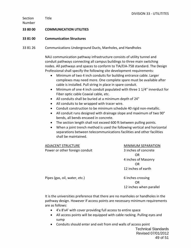
DIVISION 33 - UTILITITES Section Title Number
Technical Standards Revised 07/01/2012
49 of 51
33 80 00 COMMUNICATION UTILITIES 33 81 00 Communication Structures 33 81 26 Communications Underground Ducts, Manholes, and Handholes
NAU communication pathway infrastructure consists of utility tunnel and conduit pathways connecting all campus buildings to three main switching nodes. All pathways and spaces to conform to TIA/EIA-758 standard. The Design Professional shall specify the following site development requirements:
• Minimum of two 4 inch conduits for building entrance cable. Larger complexes may need more. One complete spare must be available after cable is installed. Pull string in place in spare conduit.
• Minimum of one 4 inch conduit populated with three 1 1/4" innerduct for Fiber optic cable Coaxial cable, etc.
• All conduits shall be buried at a minimum depth of 24" • All conduits to be wrapped with tracer wire. • Conduit construction to be minimum schedule 40 rigid non-metallic. • All conduit runs designed with drainage slope and maximum of two 90°
bends, all bends encased in concrete. • The section length shall not exceed 600 ft between pulling points. • When a joint trench method is used the following vertical and horizontal
separations between telecommunications facilities and other facilities shall be maintained.
ADJACENT STRUCTURE MINIMUM SEPARATION Power or other foreign conduit 3 inches of concrete OR 4 inches of Masonry OR 12 inches of earth Pipes (gas, oil, water, etc.) 6 inches crossing OR 12 inches when parallel
It is the universities preference that there are no manholes or handholes in the pathway design. However if access points are necessary minimum requirements are as follows:
• 4'x 8'x4' with cover providing full access to entire space • All access points will be equipped with cable racking. Pulling eyes and
sump • Conduits should enter and exit from end walls of access point

DIVISION 33 - UTILITITES Section Title Number
Technical Standards Revised 07/01/2012
50 of 51
33 82 00 Communications Distribution
The university campus communication system is based on a passive star architecture with three switching centers located in building 24, building 54 and building 64. All copper and optical fiber backbone cabling shall be routed to the appropriate switching center. All distribution design is the responsibility of NAU/ITS and the installation is the responsibility of the individual project. All University buildings shall be fed with twisted pair copper (number of pairs determined by NAU/ITS on a per project), minimum of 6 strands of Multi-mode optical fiber and minimum of 6 strands of single-mode optical fiber. Special applications may require more fiber strands.
33 82 01 Switching Center Terminations
Building 24 terminate twisted pair on Cook brand C-377 protector units with gas modules. Building 54 terminate twisted pair on 3M brand 4188 protector units with gas modules and 25 pair Telco connectorized hand off Cables terminated on 66M1-50 blocks mounted on 183 type blue metal backboards. Building 64 terminate twisted pair on 3M brand 4188 protector units with gas modules and 25 pair Telco connectorized hand off cables terminated on 66M1-50 blocks mounted on 183 type blue metal backboard. All optical fiber shall be terminated with keyed ST type connectors.

DIVISION 33 - UTILITITES Section Title Number
Technical Standards Revised 07/01/2012
51 of 51
33 82 13 Copper Communications Distribution Cabling Copper cable shall be PE 39 type and meet the following requirements:
• Solid annealed, bare copper conductors • Solid polyolefin insulation, color coded to telephone industry standards • Cable core filled with waterproofing compound • Aluminum shield with polyethylene jacket • 24 AWG, pair count determined by NAU/ITS per project • Cable shall meet the requirements of ANSI/CEA S-84-608
33 82 23 Optical Fiber Communications Distribution Cabling
Cable: Glass fiber, loose tube all dielectric gel filled osp cable rated for duct installation. Multi-mode 50 micron core, 125 micron cladding diameter with MIFL of 3.5db/km & 500 MHz-km @ 850nm, 1.5db/km &500 MHz-km @1300nm. Single-mode 125-micron cladding diameter with MIFL of 0.4 db/km at 1300nm and 0.3 db/km at 1550nm. Proof tested to 100kpsi. Fiber Distribution Shelf: Modular design with jumper routing guides for vertical and horizontal runs and all associated shelves, panels, interconnection couplers and hardware necessary to terminate all fibers with room for 25% growth. Wall Mount Distribution Units: Metal construction, lockable, capable of splicing and termination in same housing, all hardware necessary to terminate fiber (including cable attachment, connector panels, interconnect couplers, fan-out kits, etc.) All connectors and interconnect couplers must be from same manufacturer. Connectors: Keyed ST compatible with ceramic ferrule. Maximum attenuation of 0.4db and durability of 0.2db after 500 matings. All connectors and interconnect couplers from same manufacturer. Splice cases: Sealed, reenterable closure designed for fiber optic cable. All necessary trays, hardware, grommets, etc. to complete to manufacturer’s instructions and specifications. All splices to be fusion, no mechanical splicing. All fibers (inter and intra building) tested for continuity and tagged at both ends with building number and ID number. All fibers tested for insertion loss, both directions, at 850nm and 1350nm on multi-mode, and at 1310nm and1550nm on single-mode. All results documented. OTDR signature trace on all fibers with pertinent points documented (splice, endpoints, etc.) Only test results with University personnel present will be accepted.
**END OF SECTION**